
Radioddity HD-2
User Manual

Table of Contents
1. Product Overview
2. Screen Layout
3. Basic Functions
3.1 Power Switch
3.2 Volume Adjustment
3.3 Channel Selection
3.4 Vibration Alert (On/Off)
3.5 Menu Functions
3.6 Talkback Function
4. Advanced Functions
4.1 Voice Prompt On / Off
4.2 Low Battery Warning
4.3 Time-Out Timer (TOT)
4.4 VOX Voice Activation Function
4.5 High / Low Power Selection
4.6 Whisper Mode
4.7 One-Click Mute Function
4.8 Emergency Power Output
4.9 Power Saving Function
4.10 Tail Tone Elimination Function
4.11 Analog Sub-audio (CTCSS) / Digital Sub-audio (DCS)
4.12 NOAA Reception
4.13 Call Tone
4.14 Scan Function
4.15 Transmission End Tone
4.16 SOS Function
4.17 External Headset Specification
4.18 One-key Group Call
4.19 Vibration Alert Function
5. Technical Specifications
6. Annex 1: Default Frequencies (FRS 22 Channels)
1.Product Overview
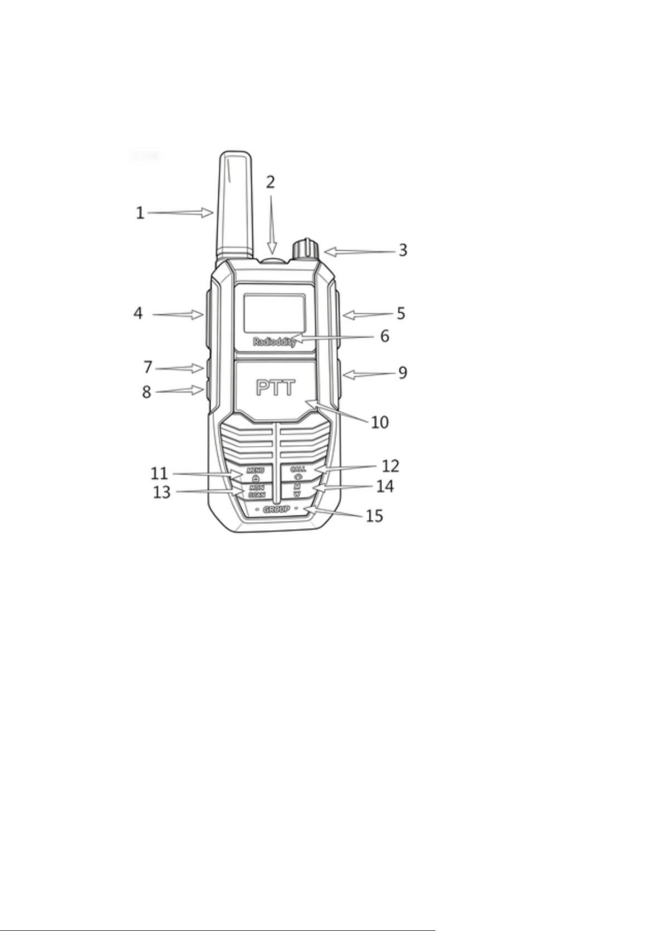
1. Antenna: Transmits and receives radio signals.
2. SOS Alarm Button: Press and hold to activate the emergency SOS alarm.
3. Volume / Power Knob: Rotate to turn the radio on/off and adjust the volume
level.
4. Side PTT (Push-To-Talk) Button: Press to transmit.
5. Headset Jack: Connects an external headset accessory.
6. LCD Display: Displays channel, power level, and other status information.
7. PF1 (▲) Up Button: Navigates upward through menu options and adjusts
settings.
8. PF2 (▼) Down Button: Navigates downward through menu options and adjusts
settings.
9. Type-C Charging Port: Used for charging the radio and reverse charging (power
output).
10. Front PTT (Push-To-Talk) Button: Press to transmit.
11. Menu Button: Short press to access and cycle through menu settings; long press
to lock the keypad.
12. CALL Button: Short press to send a call tone; long press to activate the weather
forecast.
13. Monitor / Scan Button: Short press to monitor the channel (listen for activity);
long press to start scanning.
Mute / Whisper Button: Short press for one-key mute (all incoming signals silenced);
long press to activate whisper mode (transmit at 20% normal volume for covert
operation).
15.Group Call Button: Press and hold to initiate a group call transmission.
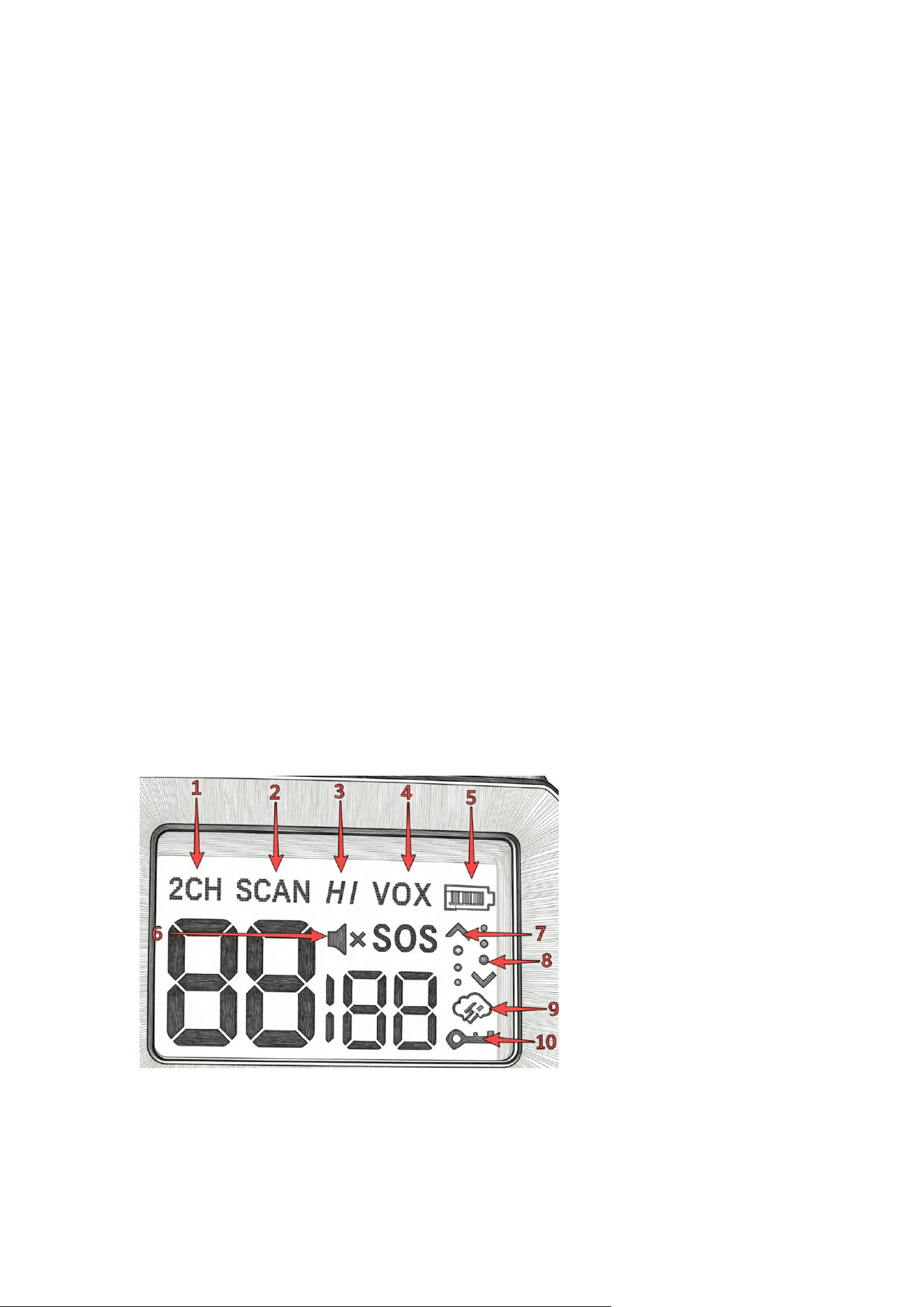
2.Screen Layout
1. Group Call Enabled (indicated by "2CH")
2. Scan
3. High Power

4. VOX (Voice-Activated Transmission)
5. Battery Level
6. Mute
7. Transmit Indicator (Arrow + Signal Animation)
8. Receive Indicator (Arrow + Signal Animation)
9. NOAA Weather
10. Keypad Lock
3.Basic Functions
3.1 Power Switch
Power On: Rotate the Power/Volume Control Knob clockwise to turn on the radio. A
click will be heard, followed by a startup tone, and the current channel will be
announced.
Power Off: Rotate the Power/Volume Control Knob counterclockwise until a click is
heard, indicating the radio is powered off.
3.2 Volume Adjustment
Rotate the Power/Volume Control Knob clockwise to increase the volume, or
counterclockwise to decrease the volume.
3.3 Channel Selection
In standby mode, press the 【MENU】 key once. The channel number will begin
flashing. Press 【▲】 or 【▼】 to select a channel.
If voice prompts are enabled, the selected channel number will be announced.
Note: Each press changes the channel by one step in a continuous loop:
Pressing 【▲】: 1→22→1→22…
pressing 【▼】: 22→1→22→1…
3.4 Vibration Alert (On/Off)
In standby mode, press the 【MENU】 key eight times to access the vibration setting.
The LCD will display "UI". Press the 【▲】 or 【▼】 side key to turn the function ON
or OFF.
ON = Vibration alert enabled;
OF = Vibration alert disabled.
3.5 Menu Functions
Menu 1: Channel Switching
Menu 2: CTCSS/DCS Tone Switching

Menu 3: Call Alert Switching
Menu 4: VOX Sensitivity Adjustment
Menu 5: High / Low Power Switching
Menu 6: Scan Switch
Menu 7: Talk End Tone Switch
Menu 8: Vibration Alert Switch
Menu 9: Off-Network Switch
3.6 Transmit Function
Press and hold the PTT button to transmit. The indicator will light up. Speak normally
into the microphone. Release the PTT button to return to receive mode.
Keep the microphone about 3–8 cm from your mouth while speaking.
Note: If the receiving radio has vibration alert enabled, it will vibrate for about 5
seconds at the start of the first transmission. During this time, audio will not be
received. Wait approximately 5 seconds before speaking to ensure your message is
heard.
4.Advanced Function
4.1 Voice Prompt On / Off
The radio supports voice prompts that announce the current channel, making
operation easier in low-light conditions.
This function can be enabled or disabled via PC programming software.
4.2 Low Battery Warning
The low battery alert will activate when the battery requires charging or
replacement.
If voice prompts are enabled, the radio will announce “Please change battery” every
120 seconds. If voice prompts are disabled, three short beeps will sound as a
reminder to recharge or replace the battery.
4.3 Time-Out Timer (TOT)
The Time-Out Timer limits continuous transmission time to prevent channel overuse.
The TOT duration can be set via PC programming software from 15 to 600 seconds, in
15-second increments.

When the preset time is reached, transmission will stop automatically and a warning
tone will sound. Release the PTT button to stop the alert. Press PTT again to resume
transmission. Default TOT is 3 minutes 30 seconds (210 seconds)
4.4 VOX Voice Activation
The VOX function allows the radio to transmit automatically when your voice is
detected.
Operation:
In standby mode, press the 【MENU】 key four times until the VOX level flashes. Use
the 【▲】 / 【▼】 keys to adjust the level (0–9). Press 【MENU】 again to save.
Level 0: VOX off
Level 9: Highest sensitivity
Notes
The higher the VOX level, the less sound is required to trigger transmission
VOX delay time determines how long the radio remains in transmit mode after you
stop speaking. It can be set via PC software to 0.5 / 1 / 1.5 / 2 / 2.5 / 3 seconds.
4.5 High / Low Power Switching
Channels 1–7 and 15–22 support selectable transmit power levels.
Each channel can be configured to High Power or Low Power via the device menu or
PC programming software. High Power provides extended communication range,
while Low Power is suitable for short-distance communication and helps prolong
battery life.
Operation:
In standby mode, press the 【MENU】 key five times until the power level flashes.
Use the 【▲】 / 【▼】 keys to switch between High and Low. Press 【MENU】 to
save.
4.6 Whisper Mode
Press and hold the M/N key to turn Whisper Mode on or off. It is specifically
designed for outdoor hunting and covert tracking scenarios.
Note: When Whisper Mode is enabled, the transmit audio volume is reduced to 20%
of the normal level.

4.7 One-Click Mute Function
Short press the M/N key to turn this function ON or OFF. It is designed for outdoor
activities, hunting and covert tracking.
Note: When Mute Mode is enabled, the radio remains completely silent for all
incoming signals.
4.8 Emergency Power Output
The USB-C port supports both charging and power output.
Charging Mode:Use the USB-C port to charge the radio.
Power Output Mode:If your mobile phone, flashlight, cigarette lighter, or other
electronic devices run out of power in the field, connect a USB cable to the USB-C
port of the radio and plug the other end into your device. The radio serves as an
emergency power supply for temporary charging, ideal for field, vehicle, and hunting
scenarios.
Note:The radio automatically switches between charging and power output modes.
No manual setting is required.
4.9 Power Saving
Power Saving Mode activates automatically when the radio receives no signals and
remains idle (no keys pressed and no channel switching), effectively reducing power
consumption.
The function is disabled automatically when a signal is received or any operation is
performed.
4.10 Tail Tone Elimination
This function reduces the squelch tail noise at the end of transmission.
It can be enabled or disabled via PC programming software.
4.11 Analog Sub-audio (CTCSS) / Digital Sub-audio (DCS)
The radio supports 50 analog (CTCSS) and 105 digital (DCS) sub-audio codes. These
can be configured via the device menu or PC programming software.

Operation:
In standby mode, press the MENU key twicetwice until the sub-audio code flashes.
Use the 【▲】 / 【▼】 keys to select a code, then press 【MENU】 to save.
Some channels may have CTCSS/DCS codes preset. These are inaudible sub-tones
that help filter out unwanted transmissions from other users on the same channel.
Only signals with a matching CTCSS/DCS code will be received. Likewise, your
transmissions will only be heard by radios using the same code.
Note: CTCSS/DCS filtering reduces interference from other users, but it does not
provide encryption or secure communication.
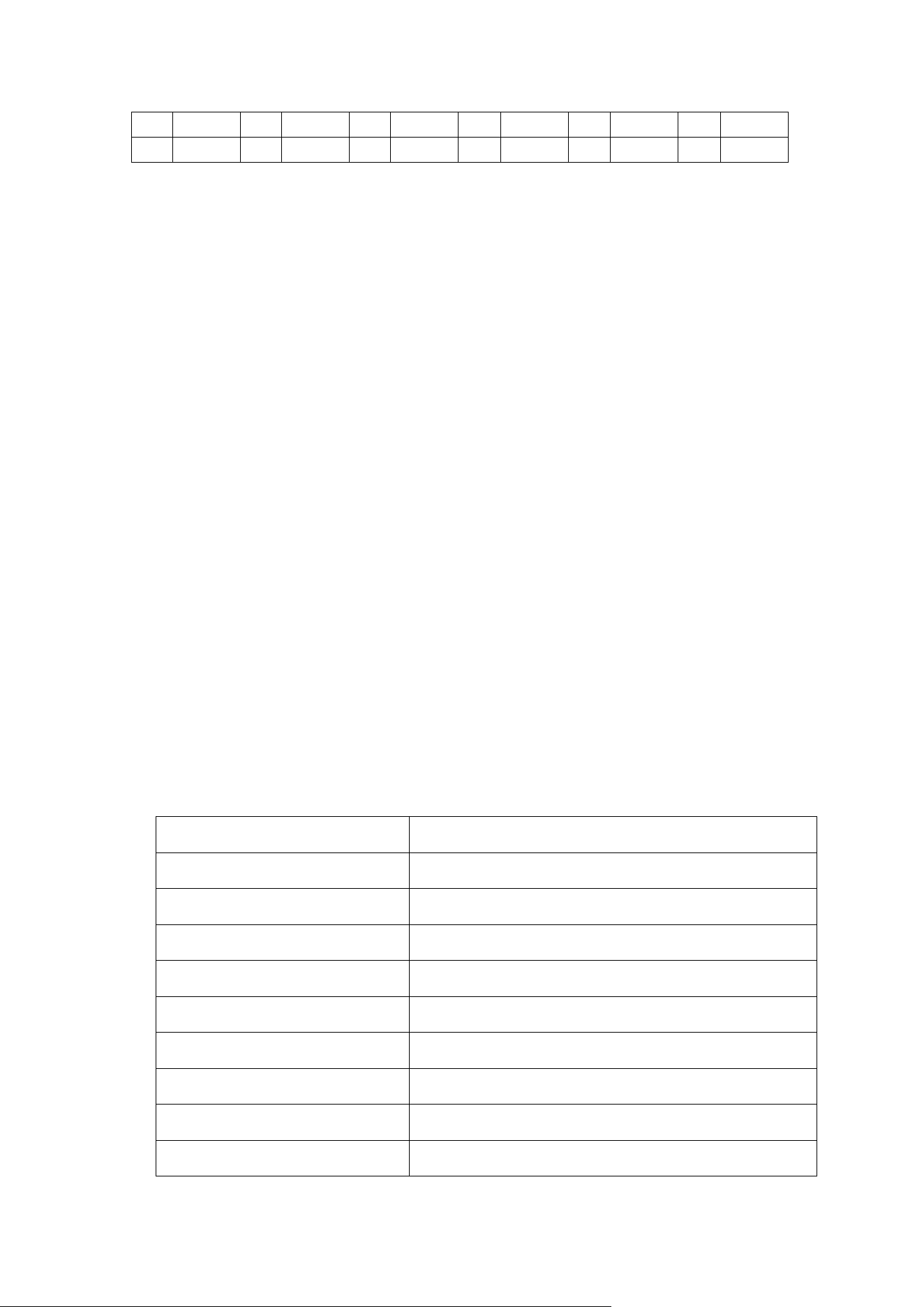
Menu 0-159 Sub-audio Comparison Table
NO.
Sub-audio
NO.
Sub-audio
NO.
Sub-audio
NO.
Sub-audio
NO.
Sub-audio
NO.
Sub-audio
0
OFF
30
167.9
60
D053N
90
D244N
120
D432N
150
D723N
1
67.0
31
171.3
61
D054N
91
D245N
121
D445N
151
D731N
2
69.3
32
173.8
62
D065N
92
D246N
122
D446N
152
D732N
3
71.9
33
177.3
63
D071N
93
D251N
123
D452N
153
D734N
4
74.4
34
179.9
64
D072N
94
D252N
124
D454N
154
D743N
5
77.0
35
183.5
65
D073N
95
D255N
125
D455N
155
D754N
6
79.7
36
186.2
66
D074N
96
D261N
126
D462N
156
D243I
7
82.5
37
189.9
67
D114N
97
D263N
127
D464N
157
D332I
8
85.4
38
192.8
68
D115N
98
D265N
128
D465N
158
D731I
9
88.5
39
196.6
69
D116N
99
D266N
129
D466N
159
D743I
10
91.5
40
199.5
70
D122N
100
D271N
130
D503N
11
94.8
41
203.5
71
D125N
101
D274N
131
D506N
12
97.4
42
206.5
72
D131N
102
D306N
132
D516N
13
100.0
43
210.7
73
D132N
103
D311N
133
0523N
14
103.5
44
218.1
74
D134N
104
D315N
134
D526N
15
107.2
45
225.7
75
D143N
105
D325N
135
D532N
16
110.9
46
229.1
76
D145N
106
D331N
136
D546N
17
114.8
47
233.6
77
D152N
107
D332N
137
D565N
18
118.8
48
241.8
78
D155N
108
D343N
138
D606N
19
123.0
49
250.3
79
D156N
109
D346N
139
D612N
20
127.3
50
254.1
80
D162N
110
D351N
140
D624N
21
131.8
51
D023N
81
D165N
111
D356N
141
D627N
22
136.5
52
D025N
82
D172N
112
D364N
142
D631N
23
141.3
53
D026N
83
D174N
113
D365N
143
D632N
24
146.2
54
D031N
84
D205N
114
D371N
144
D645N
25
151.4
55
D032N
85
D212N
115
D411N
145
D654N
26
156.7
56
D036N
86
D223N
116
D412N
146
D662N
27
159.8
57
D043N
87
D225N
117
D413N
147
D664N
28
162.2
58
D047N
88
D226N
118
D423N
148
D703N
29
165.5
59
D051N
89
D243N
119
D431N
149
D712N
4.12 NOAA Receptio
NOAA weather channels are available in the United States and Canada. While
receiving a NOAA channel, the radio cannot receive two-way radio signals.
Entering NOAA Mode: Press and hold the CALL/NOAA key to activate.
Setting a NOAA Channel:
1. In NOAA mode, press the 【MENU】 key once. The channel number will flash.
2. Use the 【▲】 / 【▼】 keys to select the appropriate NOAA channel for your
area.
3. Press and hold the CALL/NOAA key to exit.
NOAA Weather Alert
When the weather alert function is enabled, the radio will monitor the selected
NOAA channel while in standby. If an alert is broadcast, the radio will sound an alert
and automatically switch to NOAA reception to provide real-time weather updates.
When NOAA mode is active, the NOAA icon will be displayed.
Enable / Disable NOAA Weather Alert:
1. In NOAA mode, press the 【MENU】 key twice until ON or OFF flashes.
2. Use the 【▲】 / 【▼】 keys to select ON or OFF for the NOAA alert.
3. Press the 【MENU】 key to confirm and exit.
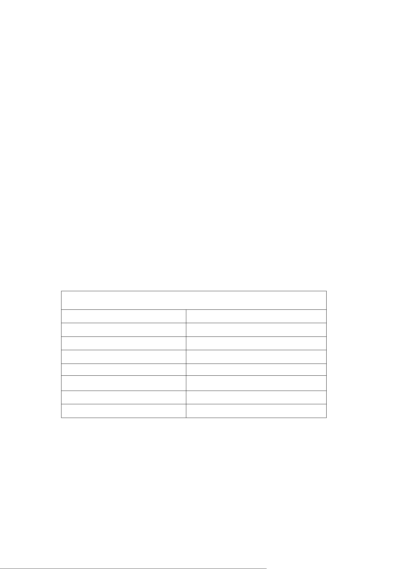
NOAA Frequency 11CH
Channel Number
Frequency (MHz)
1
162.550
2
162.400
3
162.475
4
162.425
5
162.450
6
162.500
7
162.525
8
161.650
9
162.775

10
162.750
11
162.000
4.13 CALL TONE
The Call Tone function sends an audible alert to other radios on the same channel to get
attention. When the 【CALL】 button is pressed, all radios on the same channel will ring for about
5 seconds.
Settings:
1. Press the 【MENU】 button three times until the display flashes.
2. Use the 【▲】 / 【▼】 keys to select:
00: Call Tone off
01–10: Choose from 10 different ringtone melodies.
3. Press the 【MENU】 button again to save your selection.
4.14 Scan
Enable Scan: In standby mode, press the 【MENU】 key six times until the SCAN option flashes.
Use the 【▲】 / 【▼】 keys to select ON or OFF.
Start Scanning:
Press and hold the MON/SCAN key. The radio will scan channels 1–22 automatically.
If a signal is detected, scanning will pause on that channel for communication.
If no signal is received for 5 seconds, scanning will resume.
Press and hold the MON/SCAN key again to stop scanning.
4.15 Transmission End Tone
This function can be enabled via PC programming software.
When enabled, a short tone will sound after each transmission to indicate it has ended.
4.16 SOS
Press and hold the SOS button on the top of the radio to activate the emergency alarm. All radios
on the same channel will sound the alarm.
The alarm can be stopped by turning off the transmitting radio or pressing the PTT button on that
radio.
4.17 External Headset Specification
The radio uses a standard Kenwood K-type (K-port) headset connector.
4.18 One-key Group Call
Press and hold the GROUP button, then speak. All HD-2 radios within range will receive the group
call.
4.19 Vibration Alert Function
This radio is equipped with a vibration alert feature. When receiving the first incoming
transmission, the unit will vibrate for approximately 4 seconds. Communication can only resume
after the vibration stops.
If there is no transmit or receive activity for 10 seconds after a communication ends, the
vibration alert will activate again for the next incoming signal.
Vibration alert is disabled by factory default. You may turn this function ON or OFF by accessing
the menu 8 times in sequence.
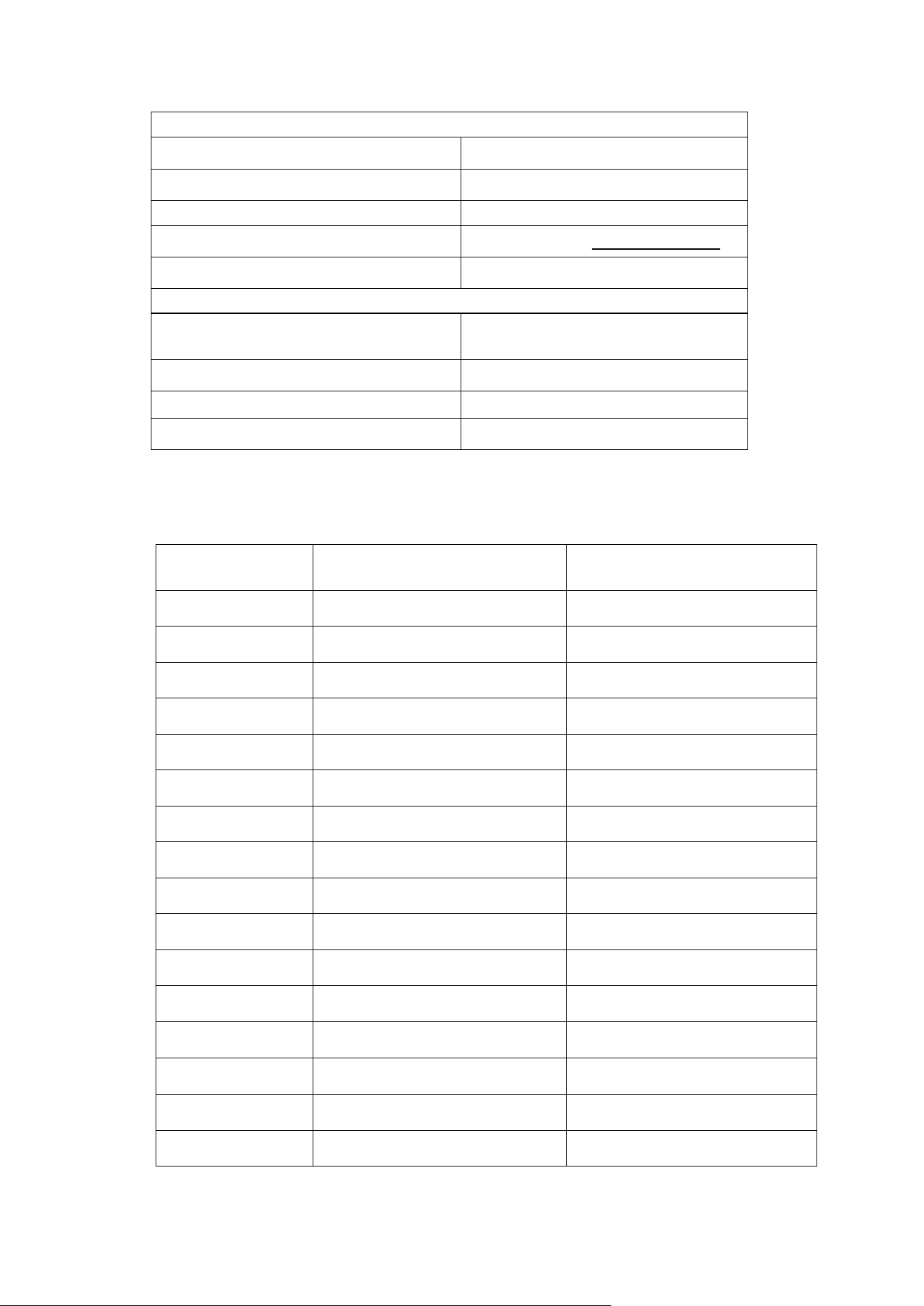
5.Technical Specifications
General
Frequency Range
FRS
Number of Channels
22
Channel Spacing
12.5KHz
Operating Voltage
3.7V
Battery Capacity
2500mAh (Li-lon)
Operating Temperature
-30°C+60°C
Antenna Impedance
50Ω
Radio Dimensions
180*65*35mm(with antenna)
Transmitter
Output Power
High: 2.0W Low: 0.5W
Frequency Stability
±2.5ppm
Neighborhood Power
60dBm@12.5KHz
Modulation Method
FM (12.5KHz@11K0F3E )
Electric Current (e.g. electrostatic)
≤1500mA
Receiver
Receiver Sensitivity
0.25uV/-119dBm (20dB S
INAD)
Audio Power
≥300mW
Audio Distortion
≤3%
Receiving Current
≤410mA
6.Annex 1 Default Frequencies (22 FRS Channels)
Channel Number
Frequency (MHz)
Power
(output)
1
462.5625
2W
2
462.5875
2W
3
462.6125
2W
4
462.6375
2W
5
462.6625
2W
6
462.6875
2W
7
462.7125
2W
8
467.5625
0.5W
9
467.5875
0.5W
10
467.6125
0.5W
11
467.6375
0.5W
12
467.6625
0.5W
13
467.6875
0.5W
14
467.7125
0.5W
15
462.5500
2W
16
462.5750
2W

17
462.6000
2W
18
462.6250
2W
19
462.6500
2W
20
462.6750
2W
21
462.7000
2W
22
462.7250
2W

FCC compliance statemen
This device complies with part 15 of the FCC Rules. Operation is subject to the following two
conditions: (1) This device may not cause harmful interference, and (2) this device must accept
any interference including received interference that may cause undesired operation.
The grantee is not responsible for any changes or modifications not expressly approved by the
party responsible for compliance. Such modifications could void the user’s authority to operate
the equipment. Replacement of any transmitter component (crystal, semiconductor, etc.) not
authorized by the FCC equipment authorization for this radio could violate FCC rules.
Note: This equipment has been tested and found to comply with the limits for a Class B digital
device, pursuant to part 15 of the FCC Rules. These limits are designed to provide reasonable
protection against harmful interference in a residential installation.
This equipment generates, uses, and can radiate radio frequency energy and, if not installed and
used in accordance with the instructions, may cause harmful interference to radio
communications. However, there is no guarantee that interference will not occur in a particular
installation.
If this equipment does cause harmful interference to radio or television reception, which can be
determined by turning the equipment off and on, the user is encouraged to try to correct the
interference by one or more of the following measures:
➢ Reorient or relocate the receiving antenna.
➢ Increase the separation between the equipment and receiver.
➢ Connect the equipment into an outlet on a circuit different from that to which the receiver is
connected.
➢ Consult the dealer or an experienced radio/TV technician for help.
FCC RF Exposure and Separation Distance
This radio complies with IEEE and ICNIRP exposure limits for occupational/controlled RF exposure
environment at operating duty factors of up to 50% and is authorized by the FCC for Occupational
Use Only. An appropriate warning label is affixed to all units. In order to comply with RF exposure
requirements, a minimum distance of 2.5 cm must be maintained when held-to-face, and
body-worn operations are restricted to the approved original accessories (belt
clip), a minimum distance of 0 cm. Do not use this device when antenna shows obvious damages.
WARNING: MODIFICATION OF THIS DEVICE TO RECEIVE CELLULAR RADIOTELEPHONE SERVICE
SIGNALS IS PROHIBITED UNDER FCC RULES AND FEDERAL LAW
Sain3 LLC
251 Little Falls Drive Wilmington, New Castle
DE, 19808
Website: www.radioddity.com
E-mail: support@radioddity.com