User Manual
GA-5S
Thank You for Shopping at Radioddity!
FIND TUTORIALS, SUPPORT AND MORE
https://www.radioddity.com/
https://www.facebook.com/radioddity
https://www.youtube.com/c/Radioddityradio
Two Way Radio
Table of Contents
Part I. Getting started
Chapter 1. - Initial setup
Safety Information
What's in the box
Available Accessories: https://www.radioddity.com/
Notice
Antenna
Belt clip
Battery
Charging and battery maintenance
Charging
Battery Maintenance
Chapter 2. - Getting to know your radio
The main display
Battery Level Indicator
Status LED
01
01
03
04
04
04
05
06
07
07
09
10
12
14
14
Visit Radioddity.com For Downloads And Help
Side key 1 - CALL (Broadcast FM and Alarm)
Side key 2 - MONI (Monitor and Flashlight)
VFO /MR-mode key
A/B select key
Numeric keypad
Pound # Key
Star * Key
Menu and function keys
Accessory jack
Chapter 3. - Basic Use
Power and volume
Turning the unit on
Turning the unit off
Adjusting the volume
Making a call
14
15
15
15
16
16
17
17
18
19
19
19
20
20
20
Channel selection
Frequency (VFO) mode
Channel (MR) mode
Part ll. Advanced topics
Chapter 4. - Working the menu system
Basic use
Using short-cuts
Chapter 5. - Scanning
Scanning modes
Time operation
Carrier operation
Search operation
Scanning a Frequency Range (VFO Mode)
Scanning Your Selected Channels (Channel Mode)
Tone Scanning
Scanning for CTCSS and DCS Tones/Codes
21
21
24
25
25
26
27
27
28
28
28
29
29
30
31
Visit Radioddity.com For Downloads And Help
Visit Radioddity.com For Downloads And Help
Chapter 6. - Dual Watch
Chapter 7. - DTMF
Chapter 8. - Selective calling
CTCSS
DCS
1000Hz, 1450Hz, 1750Hz Tone-burst
Chapter 9. - Customization
Display
Power-on message
Chapter 10. - Programming
Manual programming
Simplex channels
Duplex channels
Computer programming
32
34
36
37
38
39
40
40
42
44
44
45
46
46
Part lll. How-to and setup guides
Chapter 11. - Repeaters
Chapter 12. - Application Specific Setup
Commercial Radio Setup
Amateur Radio Setup
FRS, GMRS, MURS, PMR446
Appendix A. – Troubleshooting
Appendix B. - Menu definitions
Appendix C. - Technical specifications
General
Transmitter
Receiver
DCS table
CTCSS table
48
51
51
52
53
53
54
62
62
63
63
64
66
Visit Radioddity.com For Downloads And Help
Visit Radioddity.com For Downloads And Help
The following safety precautions should always be observed during operation,
service and repair of this equipment.
● Qualified technicians shall service this equipment only.
● Do not tamper the radio for any reason.
● Use only Radioddity radio supplied or approved batteries and chargers.
● Do not use any portable radio with a damaged antenna. If a damaged antenna
comes into contact with your skin, a minor burn can result.
● Turn off your radio prior when entering any area with explosive and flammable
materials.
● Do not charge your battery in the area with explosive and flammable materials.
● To avoid electromagnetic interference and/or compatibility conflicts, please turn off
your radio in any area where posted notices instruct you to do so
Visit Radioddity.com For Downloads And Help
01
Chapter 1.-Initial setup
Safety Information
● CHAPTER 1 INITIAL SETUP
● CHAPTER 2 GETTING TO KNOW YOUR RADIO
● CHAPTER 3 BASIC USE
Part I Getting Started
Part one covers the basic setup and use of
your hand-held two-way transceiver.
● Turn off your radio before boarding an aircraft; any use of a radio must be in
accordance with airline regulations or crew instructions.
● Turn off your radio before entering a blasting area.
● Do not place a radio over an air bag area or in the air bag deployment area for
vehicles with an air bag.
● Do not expose the radio under direct sunlight over a long time, nor place it close
to heating source.
● When transmitting with a portable radio, hold the radio in a vertical position with
the microphone 3 to 4 centimeters away from your lips; also make sure the antenna
stays at least 2.5 centimeters away from your body when transmitting.
FIND TUTORIALS, SUPPORT AND MORE
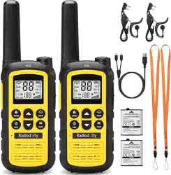
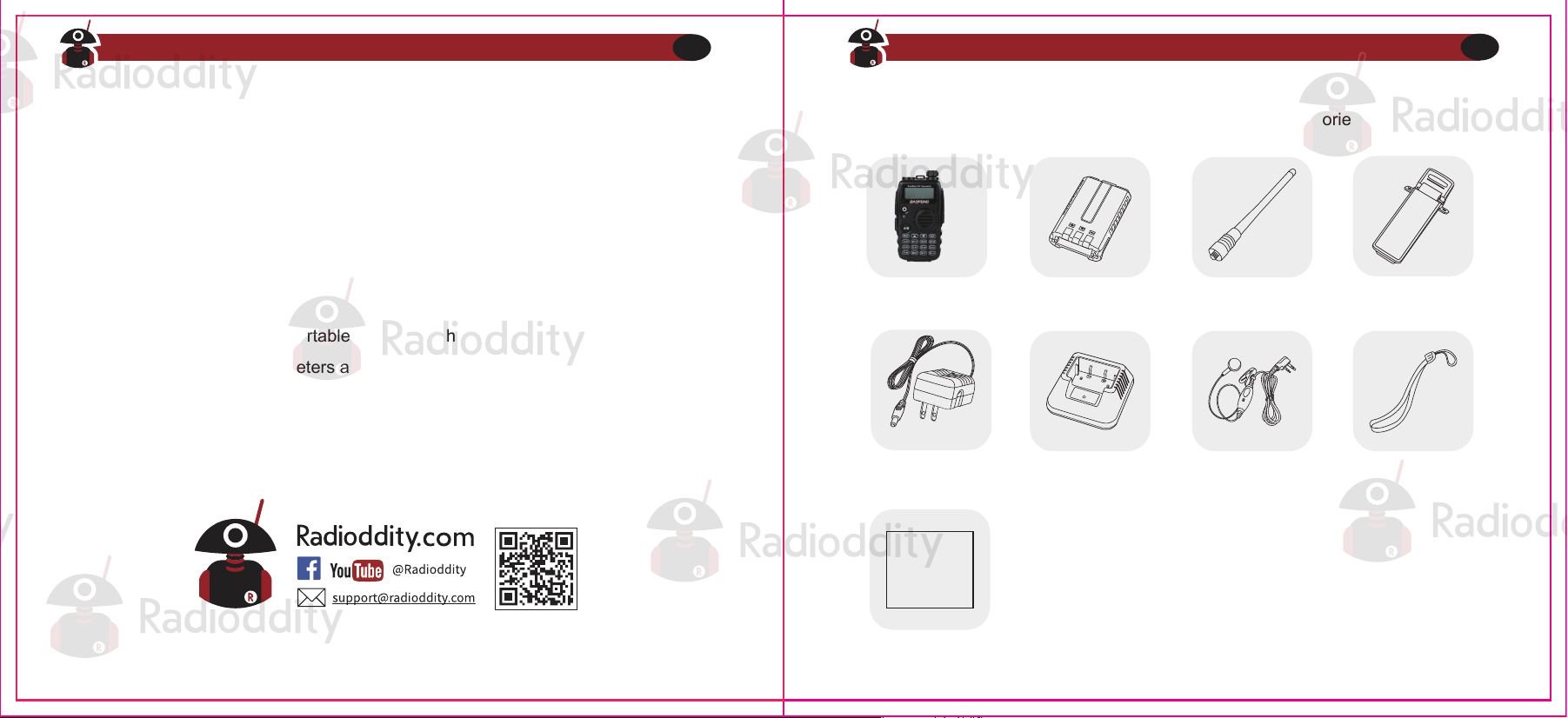
This transceiver comes shipped with below items and accessories in the box:
GA-5S Radio 1800mAh Battery Dual Band Antenna
Desktop Charger Earpiece Kit Wrist Strap
Belt Clip
User manual
User Manual
Adapter
Visit Radioddity.com For Downloads And Help
02
Visit Radioddity.com For Downloads And Help
03
What’s in the box
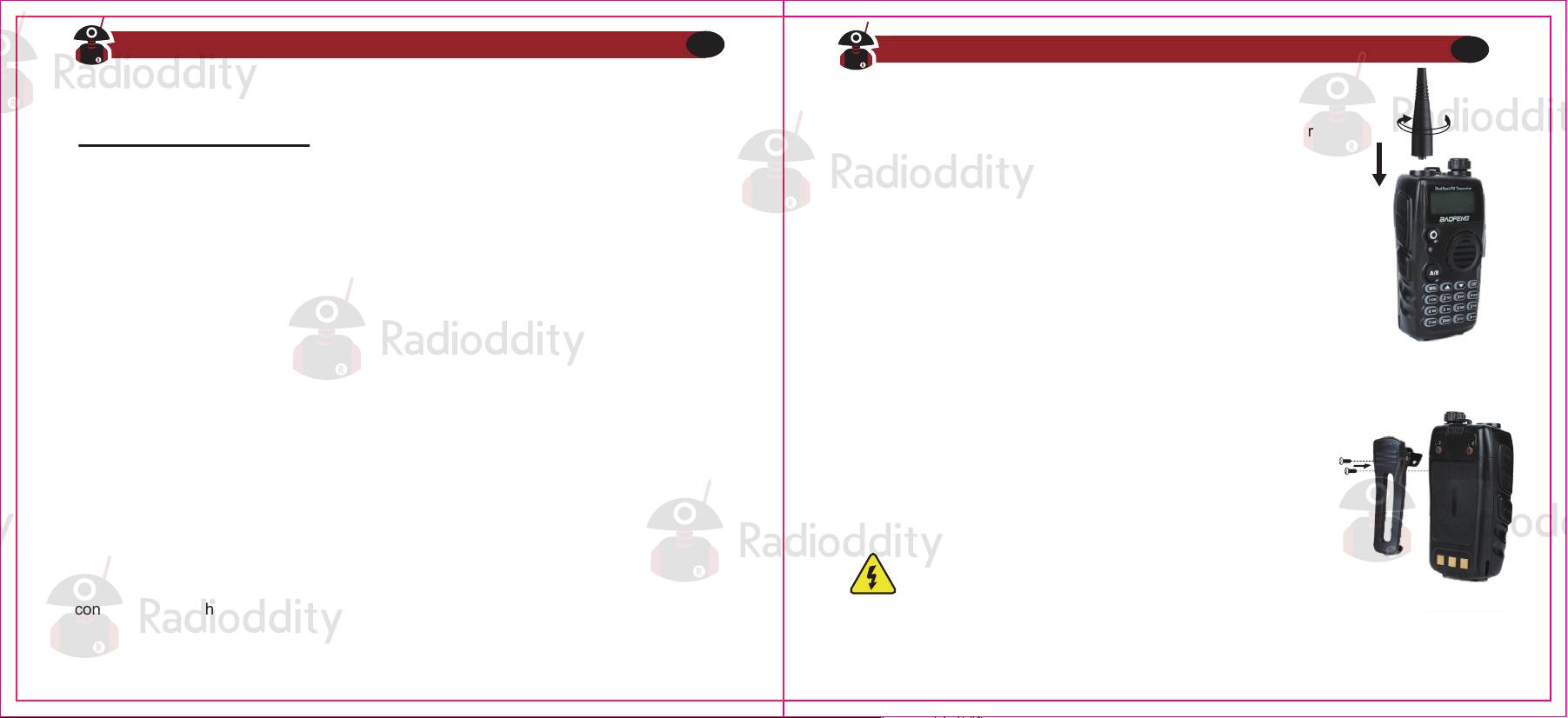
Please make sure to install the antenna and battery is charged when start using a radio.
This transceiver is fitted with a Male SMA connector. To mount your antenna (Female SMA
connector), align the two connectors and turn clockwise until it stops.
● Do not over-tighten your antenna to avoid damage to the outer
materials and the connect base.
● When installing the antenna, please remember to grip it by the
base and screw.
● When you choose using an external antenna, make sure its SWR
is about 1.5:1 or lower to avoid damage to the transceiver.
● Do not hold the antenna with your hand or wrap the outside of it to
avoid interference to the transceiver.
● Never transmitting without an antenna.
There are two parallel screws mounted on rear radio body, remove
them and thread through the holes on the belt clip as you screw
them back into the radio body.
Notice
Antenna
Belt clip
Do not add any form of glue to fix the screws on the
battery clip.The solvents in the glue may cause damage
to the battery casing.
The radio is compatible with other accessories which are available on:
https://www.radioddity.com/
Visit Radioddity.com For Downloads And Help
04
Visit Radioddity.com For Downloads And Help
05
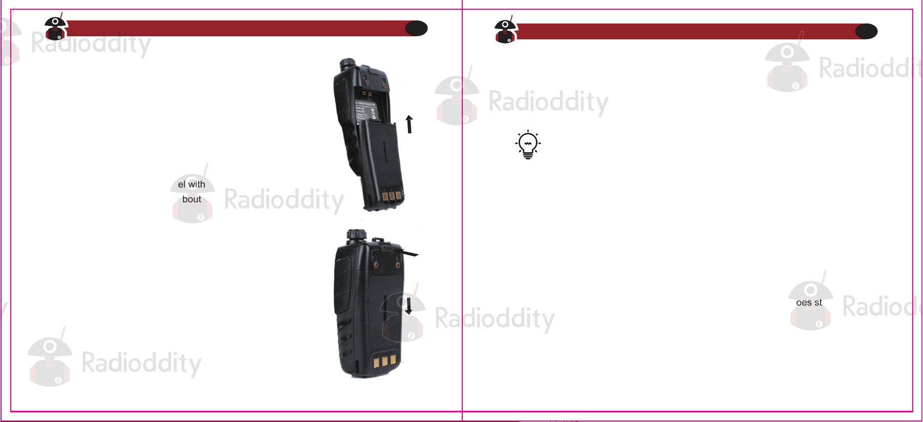
The radio must be powered off before attaching or
removing the battery, you may rotate the power/volume
knob all the way counter-clockwise to make sure it has
been turned off.
Push the battery slowly in parallel with the radio body,
the lower edge of the battery is about 1-2 cm below the
radio’s edge.
Once aligned with the guide-rails, slide the battery
upward until you hear a click to lock the battery in
place.
Battery
Installation
To remove the battery, press “PUSH” buckle on the middle top
(see Figure 2. 1,”Radioddity GA-5S Radio, overview”), as you
slide the battery downward.
Removal
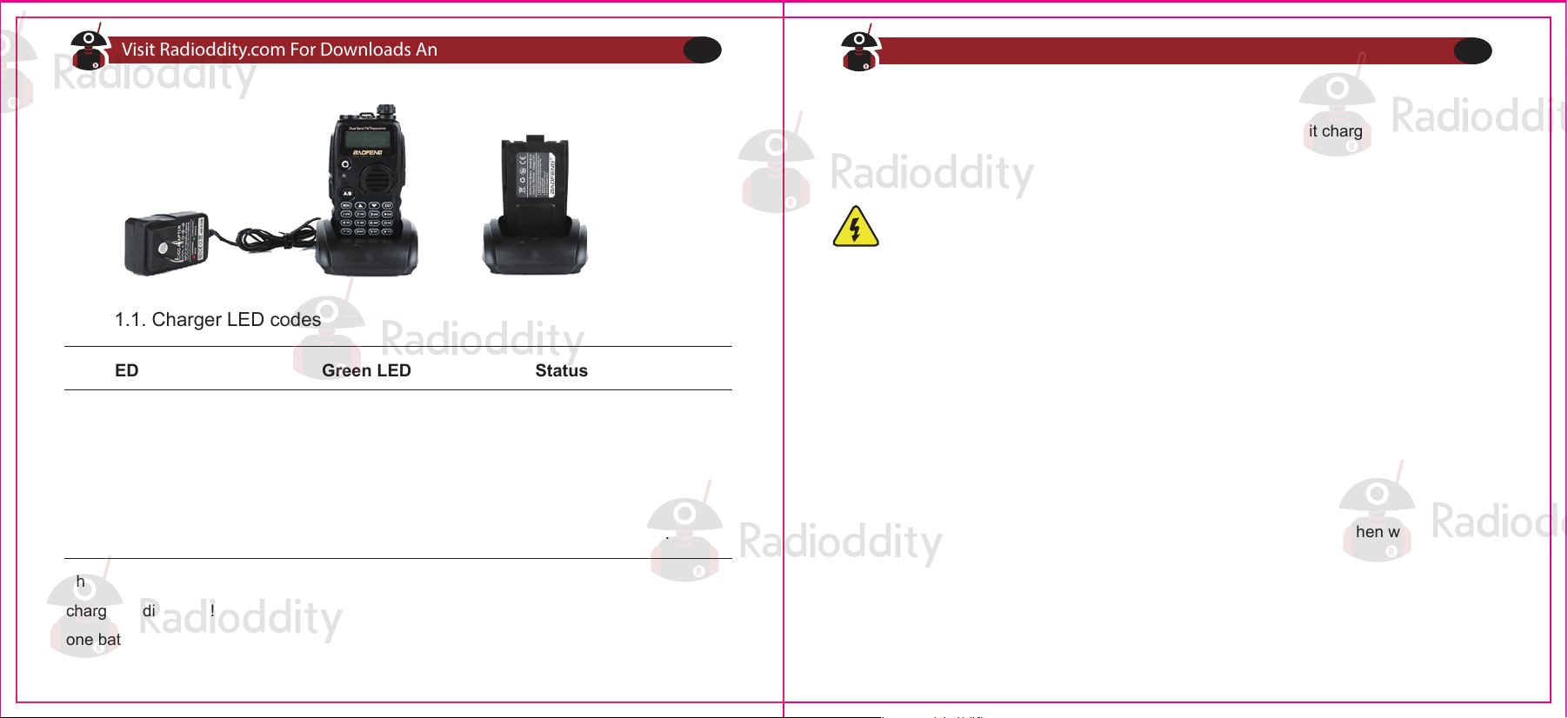
How to hook up and use the charger correctly:
1. Plug the DC connector of the power adaptor into the charger base.
2. Plug the AC connector of the power adaptor into a main ac wall outlet.
3. Place the radio in the charging base.
4. Make sure the radio is making contact with the charger. When the red LED
comes on steady, your radio is charging.
5. The radio is fully charged once the charger’s green status LED goes steady.
Please remove the radio at that time to avoid the over-charging.
Charging and battery maintenance
Charging
Battery should be fully charged before initial use. Optimum battery efficiency
will be achieved after the three full battery charge and discharge cycles.
Visit Radioddity.com For Downloads And Help
06
Visit Radioddity.com For Downloads And Help
07
The charger and battery are fitted with matching notches so that the battery can be
charged individually! That is very practical if you have two batteries, that you can charge
one battery while still using your radio.
The battery is provided without power from the factory; please let it charged for at least four
to five hours before you start using your radio.
Only charging batteries in normal room temperatures.
● When charging a battery attached to the radio, power off the radio for a faster charge.
Before the charging is completed, do not unplug the power to the charger or remove the
battery.
● Never charge or use a wet battery.
● Batteries wear out over time. When the radio is operated in a shorter time, please consider
purchasing a new battery to replace.
● Battery’s performance will be reduced in temperatures below Zero. When working in cold
environments, it is suggested to prepare a spare battery. Preferably inside your jacket or in a
similar location in order to keep the battery warm.
● Dust can interfere with the connection between battery and the radio. lf necessary wipe the
contacts with a clean cloth to ensure proper contact with radio and charger.
Battery Maintenance
Prolonging your battery’s life
Table 1.1. Charger LED codes
Red LED Green LED Status
Standby (charger empty)
Error (charger with radio)
Flashing Steady
Steady Off Charging
Off Steady Charge complete.
Visit Radioddity.com For Downloads And Help
08
Visit Radioddity.com For Downloads And Help
09
● Use only batteries approved by the original manufacturer.
● Never attempt to disassemble your battery pack.
● Do not expose your batteries to fire or intense heat
● Dispose of batteries in accordance with local recycling regulations.
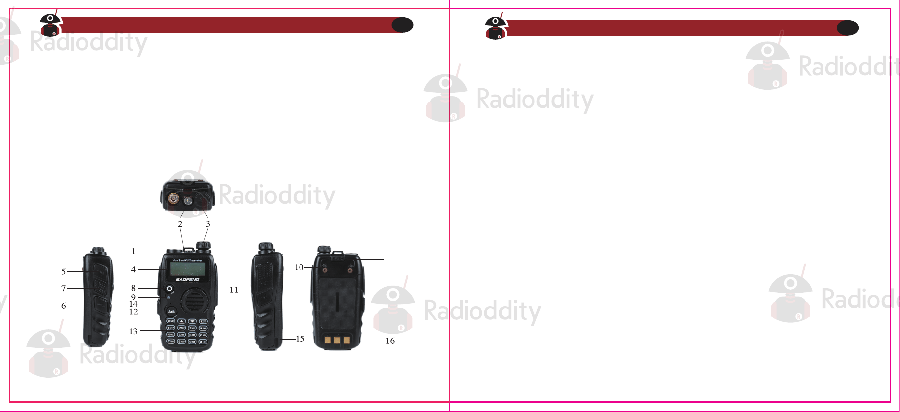
1. Antenna, see the section called "Notice" for details.
2. LED flashlight-See the section called "Side key 2 - MONI
(Monitor and Flashlight)" for more information.
3. Power/ Volume knob, usage discussed in the section called "Power and volume".
4. Two-line LCD
5. Call key
6. Monitor key
7. PTT key, usage discussed in the section called "Making a call'
8. VFO / MR mode key
9. Status LED
10. Starap buckle
11. Accessory jack
12. A / B select key
13. Keypad
14. SP.&MIC
15. Battery pack; see the section called "Charging
and battery maintenance" for detailsLanyard loop
16. Battery contacts
17. Battery remove button
In order to prevent damage from over discharge, the battery must be left with partial power.
This radio uses a lithium-based battery and a 40% charge is recommended. This level
minimizes age-related capacity loss while keeping the battery in operating condition and
allowing self-discharge.
Storage
Chapter 2. - Getting to know your radio
Figure 2.1. Radioddity GA-5S, overview
17
Visit Radioddity.com For Downloads And Help
10
Visit Radioddity.com For Downloads And Help
11
Please make sure to install the antenna and battery is charged when start using a radio.
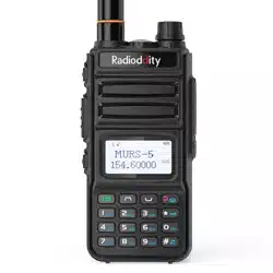
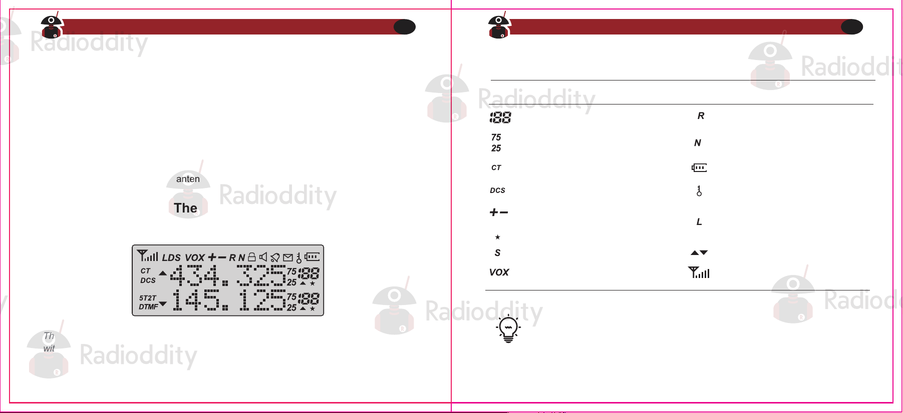
The transceiver is fitted with a seven character by two line dot matrix alphanumeric LCD,
with auxiliary icons for miscellaneous features.
Even though it is a seven character by two-line display, channel memories are
only configurable to six character names.
● Do not over-tighten your antenna to avoid damage to the outer materials and the
connect base.
● When installing the antenna, please remember to grip it by the base and screw.
● When you choose using an external antenna, make sure its SWR is about 1.5:1 or
lower to avoid damage to the transceiver.
● Do not hold the antenna with your hand or wrap the outside of it to avoid interference
to the transceiver.
● Never transmitting without an antenna.
Figure 2,2. Radioddity , display
Table 2.1. Charger LED codes
Icon Description Icon Description
Reverse function enabled
Narrowband enabled
Memory channel
Least significant modifiers
Battery level indicator
Keypad lock enabled
High Power enabled When
X7 not Displayed
Low Power Enabled
Squelch Open/Close Indicator
Indicates active band or
channel
CTCSS enabled
DCS enabled
Channel Scan Enabled
Frequency shift direction
(Offset) Channel
Dual watch enabled
VOX enabled
Visit Radioddity.com For Downloads And Help
12
Visit Radioddity.com For Downloads And Help
13
The main display
Battery Level Indicator
VFO / MR - mode key
A / B select key
The status LED has a very simple and traditional design. When you receive a signal it
shows green, when you transmit it shows red, and it's off in standby.
Status LED
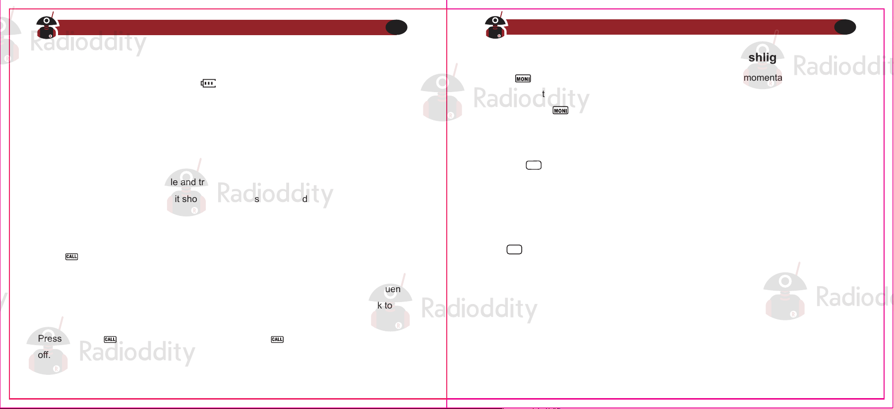
When the battery level indicator reads the battery is depleted. At this point the radio
will start beeping periodically as well as flashing the backlight of the display and when
voice prompts are enabled, a "Low Voltage" announcement will be heard, indicating that
you need to change your battery or put your radio in the charger.
Side key 1 - CALL (Broadcast FM and Alarm)
Press momentarily to start the broadcast FM receiver. Another momentary press turns
the broadcast FM receiver off. If a signal is received on the active frequency or channel
while you are listening to the broadcast FM, the squelch will be activated to that frequency
(as if scanning) and remain there until the signal goes away; it will then switch back to
broadcast FM.
Press and hold to activate the alarm function. Press (a short press) again to turn it
off.
Side key 2 - MONI (Monitor and Flashlight)
Press momentarily to turn on the LED flashlight. Another momentary press will flash
the LED. Another momentary press turns the flashlight off.
Press and hold to monitor the signal. This will open up the squelch so you can listen
to the unfiltered signal.
Pressing switches between Frequency (VFO) Mode and Memory (MR) mode.
Memory mode is sometimes also referred to as Channel mode.
To save frequencies to channel memory you must be in Frequency (VFO) mode.
VFO/MR
The key switches between A (upper) and B (lower) displays. The frequency or
channel on the selected display becomes the active listening and transmit frequency
or channel.
A/B
Visit Radioddity.com For Downloads And Help
14
Visit Radioddity.com For Downloads And Help
15
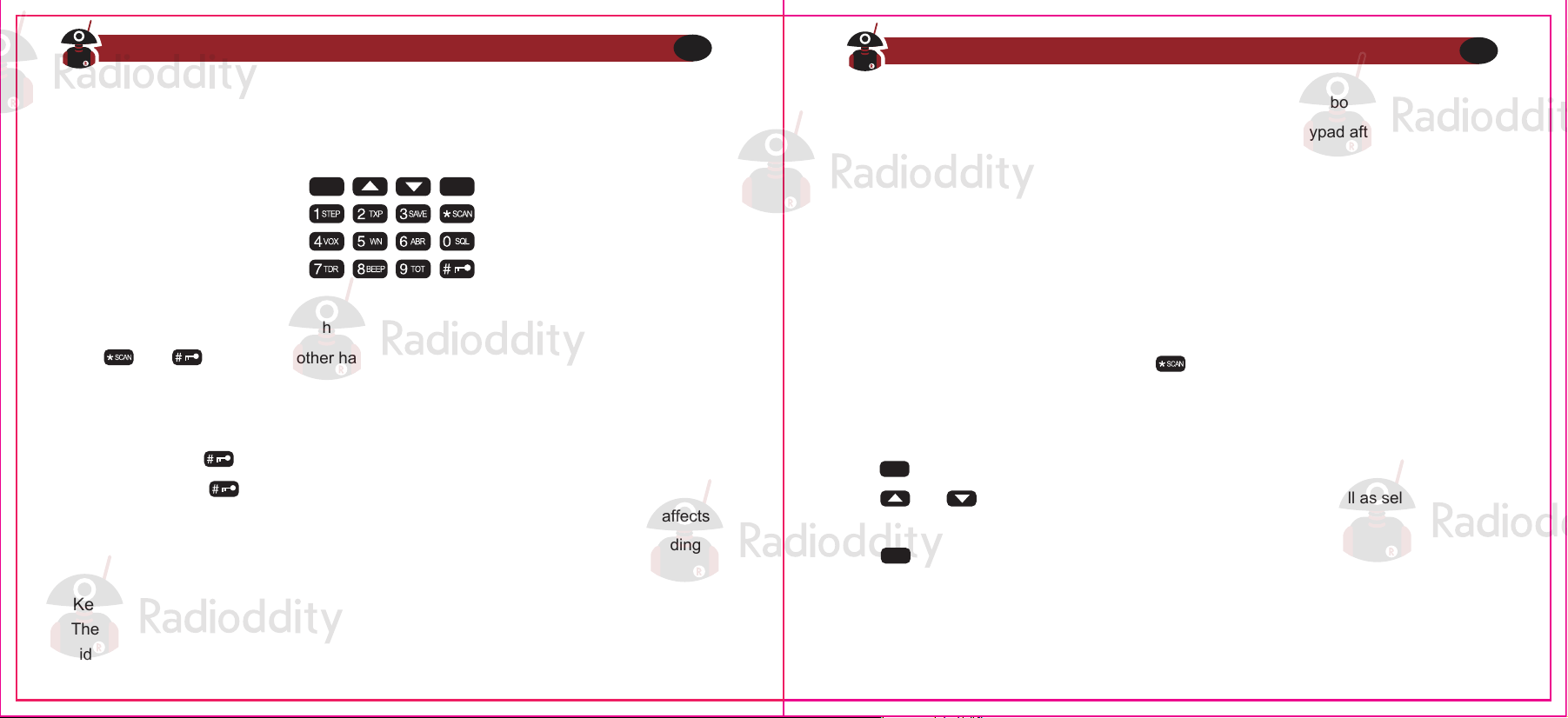
Numeric keypad
Figure 2.3. Radioddity GA-5S, keypad
Pound # Key
Keypad Lock
The Radioddity GA-5S hand-held transceiver comes standard with a full numeric keypad.
The numeric keys have their secondary function printed on them (in reality it's rather
menu short-cuts, more on that in Chapter4, Working the menu system).
The Radioddity GA-5S features a keypad lock that locks out all keys except for the three
side keys.
Star * Key
Menu and function keys
A short momentary press of the key enables the reverse function (see Chapter 11
Repeaters). When listening to broadcast FM a momentary press will start the scanning.
Scanning in broadcast FM will stop as soon as an active station is found, regardless of
scanner resume method.
The key, used to enter the menu and confirm menu options.
The and keys are used to navigate through the menu as well as select channels
and step up or down in frequency (depending on operating mode).
The key is used to exit menus and cancel menu options.
For a more in-depth explanation on how to work the menu see Chapter4, Working the
menu system.
To enable the scanner, press and hold the key for about two seconds. See Chapter
5, Scanning for details.
To enable or disable the keypad lock, press and hold the key for about two seconds.
You can also enable so that the radio automatically locks the keypad after ten seconds
from the menu, see Chapter 4, Working the menu system.
The and keys on the other hand have actual secondary functions, scan and
keypad lock respectively.
In channel mode, also acts as a transmit power shift key. While in channel mode,
momentarily press to change between High and Low transmit power. Do note that
this is does not alter the transmit power stored to memory for that channel; it only affects
the current session. Switching to another channel or another operating mode (including
broadcast FM) will reset transmit power to what's stored in channel memory.
MENU
EXIT
EXIT
MENU
Visit Radioddity.com For Downloads And Help
16
Visit Radioddity.com For Downloads And Help
17
Accessory jack
Chapter 3. - Basic Use
Power and volume
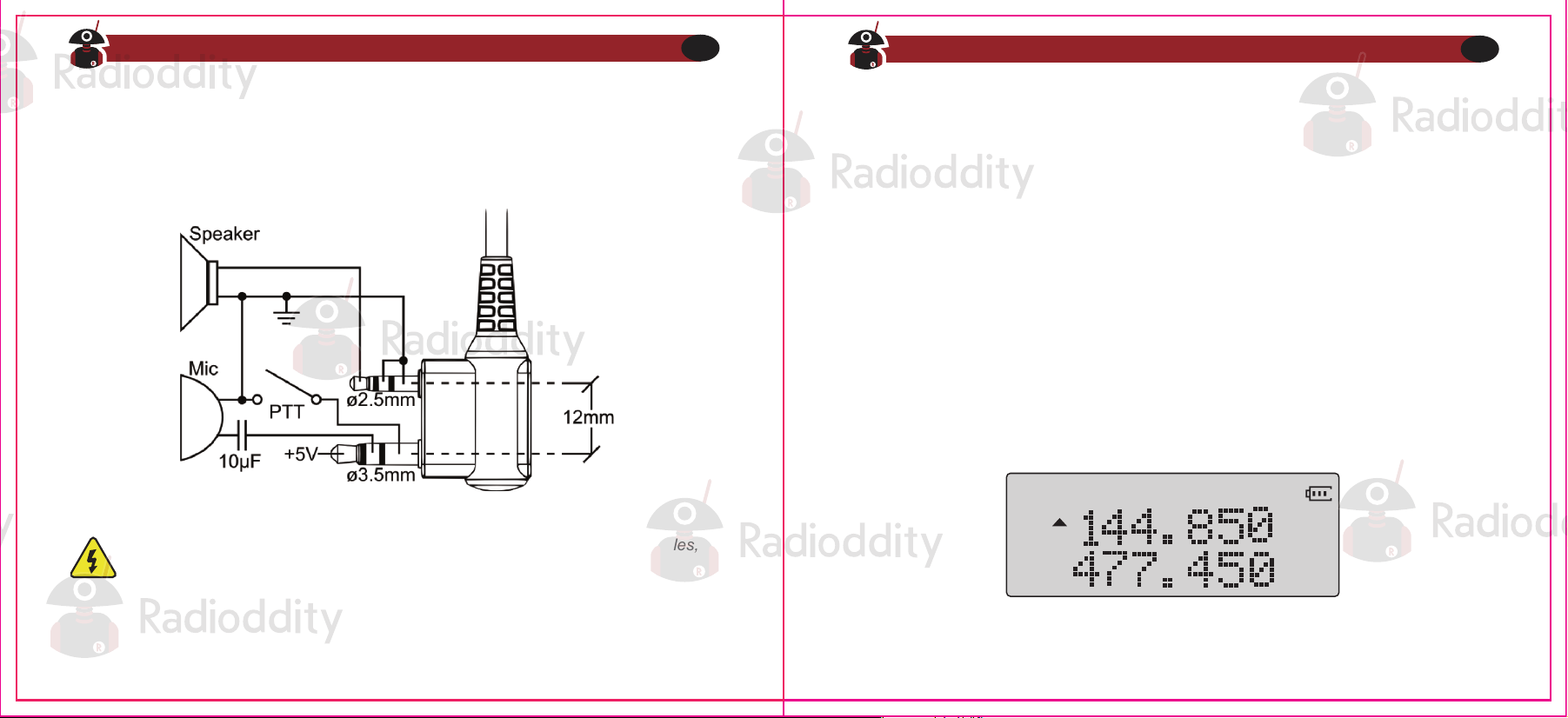
Figure 2.4. Typical 2 pin Kenwood headset configuration.
The accessory jack on the Radioddity GA-5S is a Kenwood compatible two (2)-pin design
Before we turn the power on, make sure you have attached the battery and antenna as
described in Chapter 1, Initial setup.
Turning the unit on
Figure 3.1 First power-on, display
To power the radio on, simply rotate the volume/power knob clockwise until you hear a
“click”. If your radio powers on correctly there should be an audible double beep after about
one second and the display will show a message or flash the LCD depending on settings
for about one second (see "38 PON MSG - Power On Message" in Appendix B' Menu
definitions). Then it will display a frequency or channel. If the Voice prompt is enabled, the
voice will announce "frequency mode" or "channel mode”.
To attach accessories such as headsets, speaker-mics or programming cables,
align the connectors and push in fully.
You can get additional information about your radio when you turn it on by holding down
miscellaneous keys as you turn it on.
Visit Radioddity.com For Downloads And Help
18
Visit Radioddity.com For Downloads And Help
19
Turning the unit off
Making a call
Press and hold the PTT button on the side of the radio body to transmit. While transmitting,
speak approximately 3-5cm from the microphone. When you release the PTT your
transceiver will go back to receive mode.
Channel selection
There are two modes of operation: Frequency (VFO) mode, and Channel or Memory (MR)
mode.
For daily use, Channel (MR) mode is going to be a whole lot more practical than Frequen-
cy (VFO) mode. However, Frequency (VFO) mode is very handy for experimentation out in
the field. Frequency (VFO) mode is also used for programming channels into memory. For
details on how to program your transceiver see Chapter 10, Programming.
Ultimately which mode you end up using will depend entirely on your use case.
Holding down the key while turning on the radio provides you with the
firmware version.
Turn the volume/power knob counter-clock wise all the way until you hear a "click". The
radio will be off.
Frequency (VFO) mode
Adjusting the volume
To turn up the volume, turn the volume/power knob clock-wise.
To turn the volume down, turn the volume/power knob counter-clock-wise. Be careful not to
turn it too far, as you may inadvertently turn your radio off.
By using the monitor function, enabled from the key below the PTT, you
can more easily adjust your volume by adjusting it to the un-squelched static.
In Frequency (VFO) mode you can navigate up and down the band by using the and
keys. Each press will increment or decrement your frequency according to the frequency
step you've set your transceiver to. For details on how to set the frequency step on your
transceiver see Chapter 4, Working the menu system and the section called "1 STEP -
Frequency Step1" in Appendix B, Menu definitions.
Visit Radioddity.com For Downloads And Help
20
Visit Radioddity.com For Downloads And Help
21
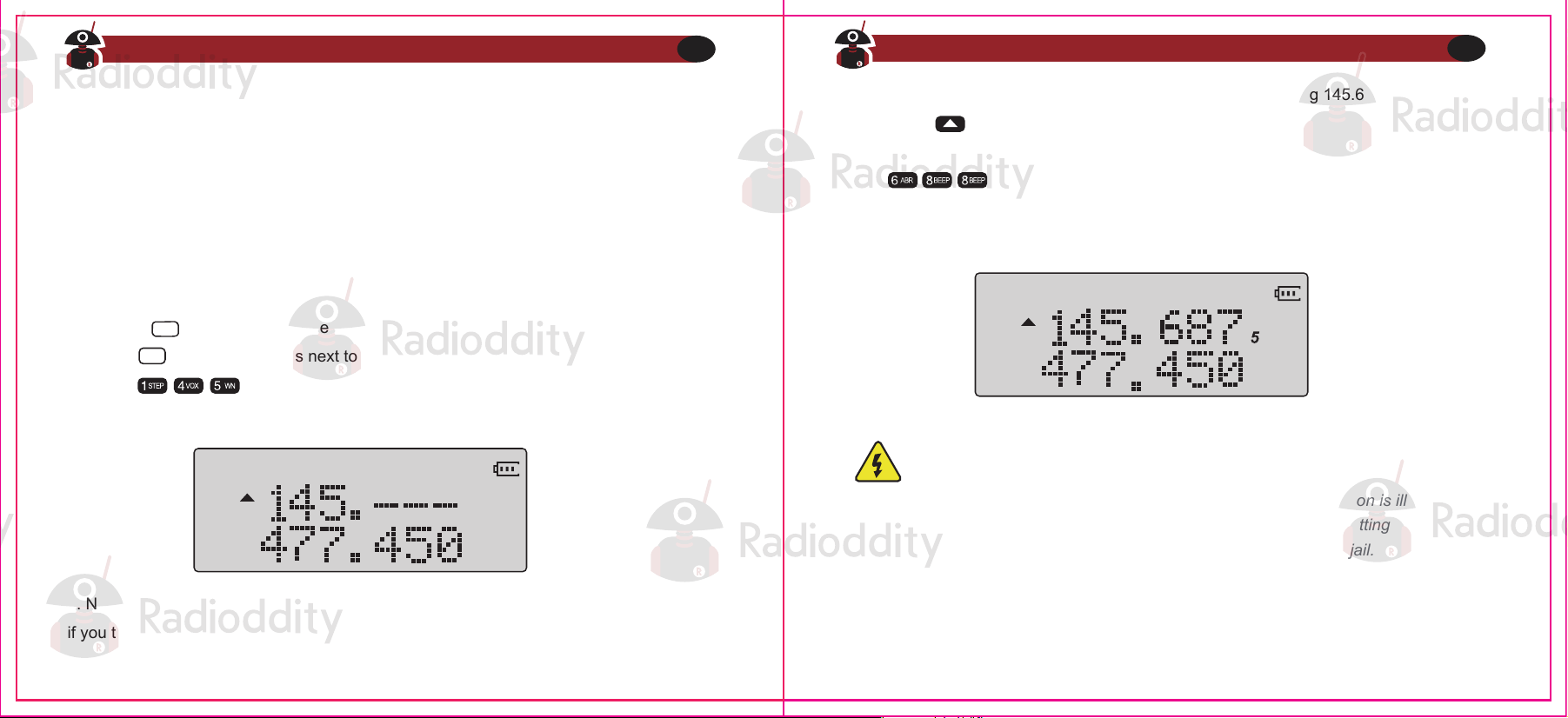
You can also input frequencies directly on your numeric keypad with kilohertz accuracy.
However, the radio will floor to the nearest frequency that corresponds to your frequency
step, in other words, when you input frequencies with greater than 1kHz resolution (such
as 145.6875 MHz in the example below), always round your input up.
The following example assumes the use of a 12.5kHz frequency step.
1. Use the key to switch to Frequency (VFO) mode
2. Press until the appears next to the upper display (display A).
3. Enter on the numeric keypad, it should look something like this:
4. Now, for the final four digits. Note that you can only enter three decimals on the keypad,
if you type 687 it won’t work. So how do you get the fourth and final digit 5 in there? By
rounding 145.6875 up to 145.6880 MHz, an alternative is entering 145.675, and then
pressing the key once to move it up to 145.6875.
Enter on the numeric keypad, if all went well the display should look
something like this:
Example 3.1. Entering the frequency 145.6875 MHz on display A
Figure 3.2. Half-entered frequency input
Figure 3.3. Successful frequency input
VFO/MR
A/B
Just because you can program in a channel does not mean you're automatically
authorized to use that frequency.
Transmitting on frequencies you're not authorized to operate on is illegal, and in
most jurisdictions a serious offence. If you get caught transmitting without a
license you can and will get fined, and in worst case sent to jail.
However, it is legal in most jurisdictions to listen. Contact your local regulatory
body for further information on what laws, rules and regulations apply to your
area.
Visit Radioddity.com For Downloads And Help
22
Visit Radioddity.com For Downloads And Help
23
Channel (MR) mode
The use of Channel (MR) mode is dependent on actually having programmed in some
channels to use. To find out more on how to program channels see Chapter 10, Program-
ming.
Once you have channels programmed and ready, you can use the and keys to
navigate between channels
If you have channels programmed with Transmit power set to Law, you can use
the key momentarily switch over to high power if you're having trouble
getting through.
Visit Radioddity.com For Downloads And Help
24
● CHAPTER 4 WORKING THE MENU SYSTEM
● CHAPTER 5 SCANNING
● CHAPTER 6 DUAL WATCH
● CHAPTER 7 DTMF
● CHAPTER 8 SELECTIVE CALLING
● CHAPTER 9 CUSTOMIZATION
● CHAPTER 10 PROGRAMMING
Part II. Advanced topics
Part two covers the more advanced topics, such as
setup of repeater offset and programming via
computer link.
Chapter 4. - Working the menu system
Basic use
For a complete reference on available menu items and parameters, see Appendix B, Menu
definitions.
Using short-cuts
Procedure 4.1. Using the menu with short-cuts
As you may have noticed if you looked at Appendix B, Menu definitions, every menu item
has a numerical value associated with it. These numbers can be used for direct access of
any given menu item.
The menu is also organized in such a way that the ten most common functions are on top,
and as can be seen in Figure 2.3,"Radioddity GA-5S, keypad", these are also printed on
the keypad so you don't have to remember them all.
The parameters also have a number associated with them, see Appendix B, Menu
definitions for details.
1. Press the key to enter the menu.
2. Use the numerical keypad to enter the number of the menu item.
3. To enter the menu item, press the key.
4. For entering the desired parameter, you have two options:
a. Use the arrow keys as we did in the previous section; or
b. Use the numerical keypad to enter the numerical short-cut code.
5. And just as in the previous section;
If your radio is set to Memory (MR) mode. The following menu items will not take
any effect: STEP, TXP, W/N, CTCSS, DCS, S-CODE, PTT-ID, BCL.SFT-D,
OFFSET, MEM-CH, BAND
MENU
MENU
1. Press the key to enter the menu.
2. Use the and keys to navigate between men u items.
3. Once you find the desired men u item, press again to select that menu item.
4. Use the and keys to select the desired parameter.
5. When you've selected the parameter you want to set for a given menu item;
a. To confirm your selection, press and it will save your setting and bring you back to
the main menu.
b. To cancel your changes, press and it will reset that menu item and bring you out of
the menu entirely.
6. To exit out of the menu at any time, press the key.
MENU
MENU
MENU
Visit Radioddity.com For Downloads And Help
25
Visit Radioddity.com For Downloads And Help
26
Chapter 5. - Scanning
Dual Watch is inhibited while scanning
To enable the scanner, press and hold the key for about two seconds. Press any key
to exit scanning mode.
The scanner is configurable to one of three ways of operation: Time, carrier or search,
each of which is explained in further details in their respective section below.
Time operation
In Time Operation (TO) mode, the scanner stops when it detects a signal, and after a
factory pre- set time out, it resumes scanning.
Carrier operation
In Carrier Operation (CO) mode, the scanner stops when it detects a signal, and after a
factory preset time with no signal it resumes scanning.
Search operation
In Search Operation (SE) mode, the scanner stops when it detects a signal.
To resume scanning you must press and hold the key again.
a. To confirm your selection, press and it will save your setting and bring you back to
the main menu.
b. To cancel your changes, press and it will reset that menu item and bring you out of
the menu entirely.
6. To exit out of the menu at any time, press the key.
7. All further examples and procedures in this manual will use the numerical menu
shortcuts.
The Radioddity GA-5S features a built in scanner for the VHF, 220MHz and UHF bands.
When in Frequency (VFO) mode it will scan in steps according to your set frequency step.
In Channel (MR) mode it will scan your channels.
MENU
EXIT
EXIT
1. Press the key to enter the menu.
2. Enter on your numeric keypad to turn to scanner mode.
3. Press the key to select.
4. Use the and keys to select scanning mode.
5. Press the key to confirm and save.
6. Press the key to exit the menu.
MENU
MENU
MENU
Procedure 5.1. Setting scanner mode
EXIT
Visit Radioddity.com For Downloads And Help
27
Visit Radioddity.com For Downloads And Help
28
Scanning modes
Scanning for a CTCSS tone or DCS code can be done while Frequency Mode (VFO) or
Channel M ode( MR) is selected .Only when VFO mode is selected, con the detected
tone/code be saved to menu 11/10.
CTCSS tone and DCS code scanning mode can be accessed with or without a
signal being present. The scanning process itself only occurs while o signal is
being received.
Not all repeaters requiring a CTCSS tone or DCS code for access will transmit one
back. In that case, the transmitter of a station that can access the repeater would
need to be scanned. In other words: this would be done by listening to stations on
the repeater's input frequency.
The UV-5RX3 can scan a user selected frequency range
The UV-5RX3 can scan your programmed memory channels; you can easily add or
remove channels from the scanning bank at any time
Scanning Your Selected Channels (Channel Mode)
Procedure 5.2.Settingscanning range
1. Press and Hold for about 2 seconds to start scanning
2. Channels with a ★ by the Channel number will be included in the scan cycle
Procedure 5.3. Scanning channels
Tone Scanning
Scanning for CTCSS and DCS Tones/Codes
1. Press and Hold for about 2 seconds
2. The Radio will begin to scan the frequency
Visit Radioddity.com For Downloads And Help
29
Visit Radioddity.com For Downloads And Help
30
Scanning a Frequency Range (VFO Mode)
Chapter 6. -Dual Watch
A flashing "DCS" will be in the left status display to indicate the radio is in DCS scanning
mode.
In this mode, whenever the radio is receiving an RF signal on the selected MR channel or
VFO frequency, the lower display will cycle through the DCS codes as they are being
tested. Once the bits of the received DCS code are determined, the "DCS" indicator will
stop flashing.
Press the key to save the scanned tone into memory (VFO Mode Only) then press
the key to exit the manual.
In certain situations, the ability to monitor two channels simultaneously can be a valuable
asset.
The Radioddity UV-5RX3 features Dual Watch functionality with the ability scans between
two frequencies at a fixed intervals and to lock the transmit frequency to one of the two
channels it monitors.
Don't forget to set VFO menu 10 back to OFF when the DCS tone is no longer
required.
MENU
Scanning for CTCSS Tone
1. Press the key to enter the menu.
2. Enter on your numeric keypad to come to Menu 11:R-CTCS
3. Press the key to select.
4. Press the to begin CTCSS scanning
MENU
MENU
A flashing "CT' will be in the left status display to indicate the radio is in CTCSS scanning
mode. In this mode, whenever the radio is receiving an RF signal on the selected MR
channel or VFO frequency, the lower display will cycle through the CTCSS tones as they
are being test. Once the frequency of the received CTCSS tone is determined, the "CT"
indicator will stop flashing.
Press the key to save the scanned tone into memory (VFO Mode Only) then press the
MENU
MENU key to exit the menu.
Scanning for a DCS tone
7. Press the key to enter the menu
8 Enter on your numeric keypad to come to Menu 10: R-DCS
9. Press the key to select.
10. Press the to begin DCS scanning
MENU
MENU
EXIT
Visit Radioddity.com For Downloads And Help
31
Visit Radioddity.com For Downloads And Help
32
Don't forget to set VFO menu 11 back to OFF when the CTCSS tone is no longer
required.
Procedure 6.1. Enabling or disabling Dual Watch mode
Chapter 7. -DTMF
Procedure 6.2. Locking the Dual Watch transmit channel
1. Press the key to enter the menu
2. Enter on the numeric keypad to get to Dual Watch.
3. Press to select.
4. Use the And keys to enable or disable.
5. Press the key to confirm.
6. Press the key to exit the menu.
Due to the way the Radioddity UV-5RX3 is constructed, whenever one of the A or B
Frequencies (VFO/MR) goes active, it will default to transmit on that channel. This behavior
can be inconvenient, especially if when monitoring a frequency, you should not transmit on.
There is a menu option available to lock the transmitter to one of the A or B channels.
DTMF is an in-band signaling method using dual sinusoidal signals for any given code.
Originally developed for tele phony systems, it has proved a very versatile tool in many
other areas.
In two-way radio systems, DTMF is most commonly used for automation systems and
remote control. A common example would be in amateur radio repeaters where some
repeaters are activated by sending out a DTMF sequence (usually a simple single-digit
sequence)
Press the key to enter the menu.
2. Enter on the numeric keypad to get to TDR-AB.
3. Press to select.
4. Use the And keys to select A (upper) or B (lower) display.
5. Press the key to confirm.
6. Press the key to exit the menu.
MENU
MENU
MENU
MENU
MENU
MENU
EXIT
EXIT
Table 7.1. DTMF frequencies and corresponding codes
Visit Radioddity.com For Downloads And Help
33
Visit Radioddity.com For Downloads And Help
34
If you want to momentarily override the lock without having to set the menu
option to OFF, you can do so by pressing the key an instant before pressing
the PTT.
A/B
697 Hz
770 Hz
852 Hz
941 Hz
1336 Hz
2
5
8
0
1633 Hz
A
B
C
D
1209 Hz
1
4
7
*
1477 Hz
3
6
9
#
Chapter 8. - Selective calling
If you have the keypad lock enabled on your radio, you can still send DTMF
tones the regular way without having to unlock your radio.
The Radioddity GA-5S has a full implementation of DTMF, including the A, B, C and D
codes.
The numerical keys, as well as the , and keys correspond to the matching DTMF
codes as you would expect The A, B, C and D codes are located in the , ,
and keys respectively (+).
To send DTMF codes, press the key(s) corresponding to the message you want to send
while holding down the PTT key.
Some times when you're working with larger groups of people using the same channel,
communication can get very crowded or disorderly. To minimize this problem, several
methods of blocking out unwanted transmissions on your frequency have developed. In
general, there are two forms of selective calling in two-way radio systems: Group calling,
and individual calling.
Group calling, as the name suggest, is a one-to-many form of communication. Every radio
in your working group is configured the same way and any radio will make contact with
every other radio in the group.
Individual calling, sometimes also known as paging, is a one-to-one form of communica-
tion.
Every radio is programmed with a unique ID code. And only by sending out a matching
code can you get that radio to open up to your transmissions.
The Radioddity GA-5S features three different ways of group calling
MENU
EXIT
● CTCSS
● DCS
● Tone-burst (1000Hz, 1450HZ, 1750Hz)
Visit Radioddity.com For Downloads And Help
35
Visit Radioddity.com For Downloads And Help
36
DCS
DCS is set with menus 10 R-DCS and 12 T-DCS
For a complete list of available DCS codes, see Table C.1, "DCS Codes" in Appendix C,
Technical specifications.
To turn CTCSS off, follow the same procedure but set it to off with the 0 SQL key instead of
selecting a CTCSS sub-tone frequency.
For more operation details, see the section called"11- Receiver CTCSS" and the section
called"13- Transmitter CTCSS" in Appendix B, Menu definitions.
CTCSS
CTCSS is set with menus 11 R-CTCS and 13 T-CTCS.
For a complete list of available CTCSS codes and corresponding sub-tone frequencies,
see Table C.2,"CTCSS Frequencies" in Appendix C, Technical specifications.
Using these features does NOT mean that others won't be able to listen in on
your transmissions
They only provide a method to filter out unwanted incoming transmissions. Any
communications mode while using these features will still be heard by anyone not
employing filtering options of their own.
Also, you cannot change the CTCSS or DCS settings while in memory (MR)
mode.
The Radioddity GA-5S does not feature any form of individual calling.
CTCSS and 1750Hz tone-burst are also popular methods among amateur radio operators
to open up repeaters.
Procedure 8. 1. CTCSS setup how-to
1.Press the key to enter the menu.
2. Enter on the numeric keypad to get to receiver CTCSS.
3. Press to select.
MENU
MENU
4. Enter desired CTCSS sub-tone frequency in hertz on the numeric keypad.
5. Press to confirm and save.
6. Enter son the numeric keypad to go to transmitter CTCSS.
7. Press to select
8. Enter desired CTCSS sub-tone frequency in hertz on the numeric keypad. Make sure it's
the same frequency as that you entered for receiver CTCSS.
9. Press to confirm and save.
10. Press to exit the menu system.
MENU
MENU
MENU
EXIT
Visit Radioddity.com For Downloads And Help
37
Visit Radioddity.com For Downloads And Help
38
1000Hz, 1450HZ, 1750HZ Tone-burst
Chapter 9. - Customization
Display
The Radioddity GA-5S allows for customization of both the power-on message (via
computer link only), and the backlight color during the three states of the transceiver
(Transmit, Receive and Standby).
The LCD on the Radioddity GA-5S is backlit by multi-color LEDs, the color of which can be
pre-set from the menu system into a variety of colors.
To change the colors, follow these steps:
Procedure 8. 2. DCS setup how-to
Procedure 9. 1. Changing backlight color
1. Press the key to enter the menu.
2. Enter on the numeric keypad to get to receiver DCS.
3. Press to select.
4. Enter desired DCS code on the numeric keypad.
5. Press to confirm and save.
6. Enter on the numeric keypad to go to transmitter DCS.
7. Press to select.
8. Enter desired DCS code on the numeric keypad. Make sure it's the same code as that
you entered for receiver DCS.
9. Press to confirm and save.
MENU
MENU
MENU
MENU
MENU
To send out a tone-burst; you simultaneously will press a key while holding down the PTT.
No further configuration required using this feature.
The following configurations will transmit accordingly:
PTT + = Transmits 1000Hz Tone Burst
PTT + = Transmits 1450Hz Tone Burst
PTT + = Transmits 1750Hz Tone Burst
VFO/MR
A/B
1. Press the key to enter the menu.
2. Enter one of the following on your numeric keypad
a. to change the standby color
b. to change the receive color.
c. to change the transmit color
3. Press key to select
MENU
MENU
Visit Radioddity.com For Downloads And Help
39
Visit Radioddity.com For Downloads And Help
40
If you have the keypad lock enabled on your radio, you can still send a 1750H/z
tone the regular way without having to unlock your radio.
Power-on message
The power-on message can only be set via computer link, see the section called "Comput-
er Programming "for details on how to setup a link with your computer.
The following instructions assume that you've already established a link using the Baofeng
software from a computer running Windows, and that the Radioddity software is already
installed and running.
Use in Conjunction with Menus 21 & 22 to coordinate what is displayed-Appendix B Menu
Definitions
3. Press key to select
4. Use the and keys to select 'ON'.
5. Press to confirm and save
6. Press to exit the menu
MENU
MENU
EXIT
To change the duration of the backlight stays on for your LCD, follow these steps:
4. Use the and keys to pick the desired color
5. Press to confirm and save
6. Press to exit the menu.
MENU
EXIT
For details see the section called "29 WT-LED- Display backlight color, Standby" and
onward in Appendix B, Menu definitions.
To sync channels on the display (simultaneously display channel name and frequency),
follow these steps:
Procedure 9.2. Setting backlight time-out
Procedure 9.3. Synching the Display
1. Press the key to enter the menu.
2. Enter on your numeric keypad to come to backlight time out.
3. Press key to select.
4. Use the and keys to pick the desired color
5. Press to confirm and save
6. Press to exit the menu.
MENU
MENU
MENU
EXIT
1. Press the key to enter the menu
2. Enter on your numeric keypad to come to the Sync Menu
MENU
Visit Radioddity.com For Downloads And Help
41
Visit Radioddity.com For Downloads And Help
42
Manual programming
Manual programming is somewhat difficult until you get used to it, especially when
programming in duplex channels. Note that the ANI S-CODE IDs can only be set from a
computer. When programming channels it is important to remember that you can only save
memory channels when working on the upper display in VFO mode.
To create a new channel, start by switching your radio to Frequency (VFO) mode using
VFO/MR key. When in Frequency (VFO) mode, select your desired receive frequency
using the numerical keypad. After that, use the menu system to configure the finer details
of the channel you're wanting to program to memory, such as transmit power, bandwidth,
CTCSS or DCS and more.
1. Click other in the menu bar; a dialogue box titled "Other" should have popped up.
2. In the box titled "Power On Message", there are two text fields representing the two lines
on your LCD. Enter the desired text in the fields.
3. Click Write to write your changes to the radio.
Procedure 9.3 . Setting the power-on-message
Chapter 10. - Programming
Memory channels are an easy way to store commonly used frequencies so that they can
easily be retrieved at a later date.
The Radioddity GA-5S features 128 memory channels that each can hold: Receive and
transmit frequencies, transmit power, group signaling information, bandwidth, ANI/ PTT-ID
settings and a six-character alphanumeric identifier or channel name 1.
Visit Radioddity.com For Downloads And Help
43
Visit Radioddity.com For Downloads And Help
44
Even though the software has eight (8) character wide text for the power-on
message, be aware that the display on the UV- 5RX3 can only display a
maximum of seven (7) characters.
Make sure that menu item 38 is set to MSG, otherwise your message won’t be
displayed. See Chapter4 Working the menu system for details on how to navigate
the menu.
Sometimes it takes the Radioddity software more than one try to connect to your
radio. If you see a dialogue box popping up stating that you have a connection
failure, close the dialogue box and click read or write again.
For more information on how to use the menu system see Chapter 4, Working the menu
system and Appendix B, Menu definitions. Information regarding how to set up CTCSS and
DCS can be found in Chapter 8, Selective calling
On manual programming you cannot overwrite an existing channel. You must first
delete the channel before updating or replacing it
Simplex channels
Duplex channels
Computer programming
The following steps assume that you're in Frequency (VFO) mode and that you’ve entered
the desired frequency to store to memory.
1. Press the key to enter the menu.
2. Enter on the numerical keypad to get to MEM-CH.
3. Press to select.
4. Use the and keys to select an empty memory channel, or enter it directly on
the numerical keypad.
5. Press the key to confirm.
6. Press the key to exit the menu.
Switch to Channel (MR) mode with the (VFO/MR) key to test your new channel. If you
would like to name your channel you will need to do that from a computer. More on that in
the section called “Computer programming”.
The following assumes you've setup a duplex channel in VFO mode on the upper display,
as described in Chapter 11, Repeaters, and that you're still in VFO mode.
1. Save as you would a regular simplex channel, as described in the previous section.
2. Press the key momentary to get into reverse mode
3. Save that again to the same memory channel just as in step one (1)
Switch to Channel (MR) mode with the key to test your new channel. If you would like
to name your channel you will need to do that from a computer. More on that in the section
called “Computer programming”.
The Radio kit does not include a programming cable. To attain a PC cable please visit
https://www.radioddity.com/
Download programming software at https://www.radioddity.com/baofeng_download/
MENU
MENU
MENU
EXIT
VFO/MR
Visit Radioddity.com For Downloads And Help
45
Visit Radioddity.com For Downloads And Help
46
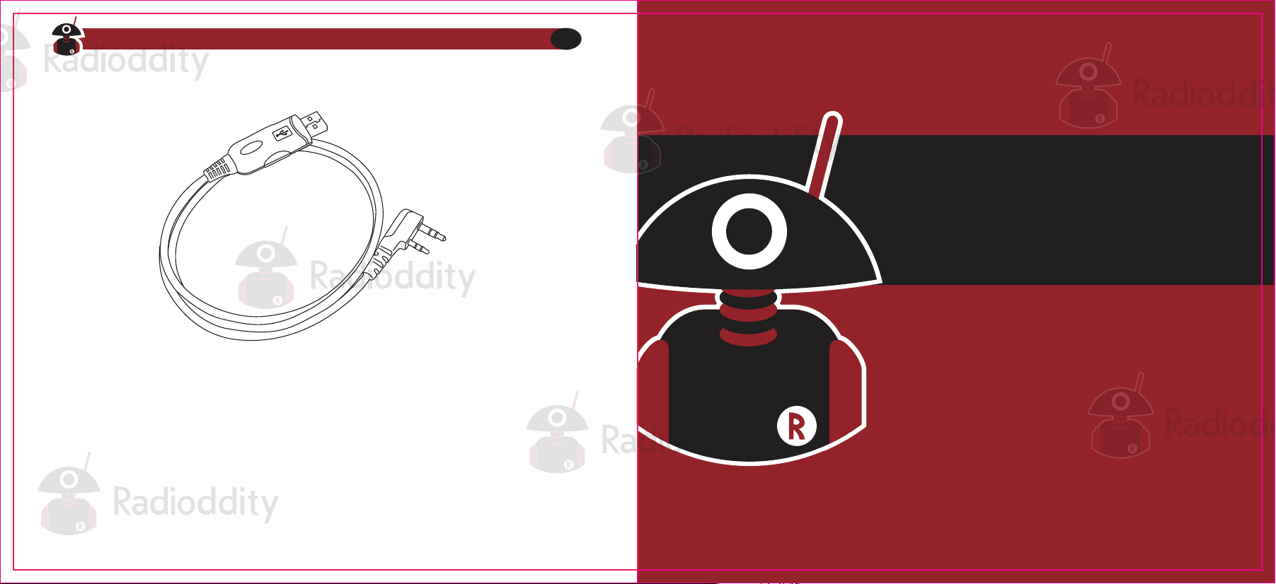
RD-201 PROGRAMMING CABLE
For GA-5S Computer Programming
Software and cable support for Windows, and Linux
Visit Radioddity.com For Downloads And Help
47
● CHAPTER 11 REPEATERS
● CHAPTER 12 AUTOMATIC NUMBER IDENTIFICATION
● CHAPTER 13 APPLICATION SPECIFIC SETUP
Part Ill. How-to and setup guides
Part three covers is a collection of how-to documents to
help you set up your radio for specific working
environments.
A radio repeater is an automated transceiver in a fixed location. Usually mounted high up
on hilltops or on tall buildings, but sometimes they operate within buildings for internal use.
A repeater takes one signal and relays it, usually after amplifying it by orders of magnitude.
This can be very handy, as this enables you to use a small low powered hand-held two-way
transceiver such as the Radioddity GA-5S to reach great distances.
Whether you're a commercial (business or government) user or an amateur radio operator,
chances are you’ll deal with a repeater system sooner or later. To find out what settings to
use to use your local repeater, ask your employer or someone at your local amateur radio
organization for details.
A common type of repeater is the duplex repeater. In a duplex repeater system, the
repeater transmits and receives simultaneously, but on different frequencies. To utilize this
type of repeater, your radio has to be capable of transmitting and receiving on different
frequencies on the same memory channel. How you use this kind of repeater is by setting
the receive frequency of your radio to the output frequency of the repeater, and the transmit
frequency of your radio to the input frequency of the repeater. Often times, the transmit
frequency to use isn't explicitly stated, but rather an offset relative your receive frequency is
specified. This is conveniently enough also how the Radioddity GA-5S natively handles
repeater set up in VFO, by specifying offset rather than transmit frequency.
The following instructions assume that you know what transmit and receive frequencies
your repeater employs, and that you’re authorized to use it.
Procedure 11.1. Repeater setup
Chapter 11. - Repeaters
1. Set the radio to Frequency (VFO) mode with the key.
2. Enter the repeater’s output (your receiving) frequency by either using the and
Keys, or entering it directly on the numerical keypad.
3. Press the key to enter the menu.
4. Enter on the on the numeric keypad to get to frequency offset.
5. Press key to select.
6. Use the and keys and numeric keypad to enter the specified frequency offset.
See the section called “26 OFFSET-Frequency shift amount” for details.
MENU
MENU
VFO/MR
Visit Radioddity.com For Downloads And Help
48
Visit Radioddity.com For Downloads And Help
49
This is might cause confusion because many expect this to be true globally when
it isn’t.
SFT-D and OFFSET only function in VFO mode.
MR mode uses and stores the RX frequency and the TX frequency only. SFT-D
and OFFSET don’t have to be set or they can even be set completely wrong and
working repeater channel can be created
It is convenient to use SFT-D and OFFSET with ‘reverse’ mode to determine the
TX frequency to be stored in a channel, but they are otherwise unused for MR
mode.
If everything went well, you should be able to make a test call through the repeater. If
you’re experiencing problems making a connection to the repeater, check your setting and/
or go through the procedure again.
Certain Amateur Radio repeater (especially in Europe) use a 1750Hz tone burst to open up
the repeater. To see how this is done with the Radioddity GA-5S, see the section called
“1750Hz Tone- burst”.
If you ‘re still unable to make a connection, contact the person in charge of the radio
system with your employer or your local amateur radio club, as the case may be.
Follow these instructions to set your radio to Narrowband mode:
7. Press to confirm and save.
8. Enter on the numeric keypad to get to offset direction.
9. Use the and keys to select +(positive) or-(negative) offset.
10. Press to firm and save.
11. Optional:
a. Save to memory, see the section called “Manual programming” for details.
b. Set up CTCSS; see the section called “CTCSS” for details.
12. Press to exit the menu.
Chapter 12. - Application Specific Setup
Commercial Radio Setup
MENU
MENU
EXIT
1. Press the key to enter frequency mode.
2. Press the key to enter the menu.
3. Enter on the numerical keypad.
4. Press to select.
5. Use the and keys to select between Wide and Narrow (“Narr”).
6. Press to confirm and save.
7. Press to exit the menu.
MENU
MENU
MENU
VFO/MR
EXIT
Visit Radioddity.com For Downloads And Help
50
Visit Radioddity.com For Downloads And Help
51
If you for some reason want to listen to the repeater’s input frequency instead,
press momentarily and you’ll reverse your transmit and receive frequen-
cies.
This is indicated in the LCD on the radio with an R in the top now, next to the +
and- for the offset direction.
This section is only true for VFO mode.
WN is settable on a per channel basis and has to be set prior to storing a channel.
Once a channel has been programmed, the channel must be deleted and
reprogrammed to change the WN setting.
Amateur Radio Setup
In contrast with Commercial radio operators, who often need very specific requirements to
be compatible with a very specific radio implementation, Amateur radio operators tend to
need the broadest possible settings in order to be compatible with as many systems as
possible. This basically implies turning all the fancy features that you typically might need
for a commercial setup off.
In a typical Amateur radio setup the following settings would be recommended:
• Set bandwidth to Wide (menu item 5).
• Turn DCS and CTCSS off (menu items 10 through 13).
• Turn ANI, DTMFST, S-CODE, PTT-ID off and PTT-LT to Oms (menu items 15 through 17
and 19 through 20).
• Turn off Squelch Tail Elimination (STE) features (menu items 35 through 37).
• Turn roger beep (ROGER) off (menu item 39).
FRS, GMRS, MURS, PMR446
For further information see Appendix B, Menu definitions and Chapter4, Working the menu
system.
If your employer has a dispatch system that requires your radio to identify via ANI,
please see Chapter 12, Automatic Number identification for detailed instructions on how
to set that up on your radio.
To find out what other channels and features needed, please contact your employer.
You may be tempted to use FRS GMRS, MURS (in the USA) or PMR446 (in
Europe) frequencies. Do note however there are restrictions on these bands that
make this transceiver illegal for use.
Appendix A. - Troubleshooting
Symptom
Possible
Soluon
The radio doesn't
start
The baery is too low.
The baery isn't correctly
installed.
Change or recharge the baery.
Remove the baery and reinstall it.
The baery dies
quickly
The baery is dead.
The baery isn't fully charged
Purchase a new baery.
Recharge the baery.
The LED indicates
recepon, but the
speaker is silent.
Others can’t hear
my transmission.
The radio transmits
without touching the
PTT.
The VOX is enabled.
VOX sensivity is too high.
Turn VOX off.
Turn down VOX sensivity.
Their CTCSS or DCS sengs
don’t match yours.
You're too far apart.
Change your CTCSS or DCS
sengs to match your peers.
Move in closer.
Volume is too low.
CTCSS or DCS enabled
Turn up the volume.
Change your CTCSS or DCS to match
those you're trying to communicate
with.
Turn CTCSS or DCS off.
Visit Radioddity.com For Downloads And Help
52
Visit Radioddity.com For Downloads And Help
53
Appendix B. - Menu definitions
See Chapter4, Working the menu system for more info about using menu-system.
Menu
0
Name
(Full Name)
SQL - Squelch
Level
[0-9]
Setting the squelch to 0 will
Open up the squelch entirely.
-Squelch silences the receiver when there
is no signal.
-Sensitivity can be varied from .1 to .3 mV
on UHF
Sensitivity can be varied from .1 to.2 mV
on VHF
1
STEP - Frequency
Step
2.5K[0] | 5.0K[1] | 6.25K[2] |
10.0K[3] | 12.5K[4] | 20.0K[5]
|25.0K[6] | 50.QK [7]
Settings
Description
Selects the amount of frequency change in
VFO/Frequency mode when scanning or
pressing the and keys.
2
TXP - Transmit
Power
HIGH [0] | LOW [1]
Selects between HIGH and LOW
transmitter power when in VFO/Frequency
mode. Use the minimum transmitter
power necessary to carry out the desired
communications.
3
SAVE - Battery
Save
OFF [0] | 1 | 2 | 3 | 4
Selects the rao of sleep cycles to awake
cycles (1:1,2:1,3:1,4:1). The higher the
number the longer the baery lasts. The
higher number increases the RX sleep cycle,
but you may miss the first few syllables
before the RX opens.
When enabled it is not necessary to push
the [PTT] buon on the transceiver. Adjust
the gain level to an appropriate sensivity to
allow smooth transmission.
Wideband (25 kHz bandwidth) or
Narrow band (12.5 kHz bandwidth).
Time-out for the LCD backlight,
(seconds)
4
5 WIDE [0] | NARR [1]
6
OFF [0] | X | 2 | 3 | 4 | 5
| 6 | 7 | S | 9 | 10
7
TDR - Dual
Watch, Dual
Reception
OFF [0] | ON [1]
Monitor [A] and [B] at the same me. The
display with the most recent acvity ([A]
8
BEEP - Keypad
Beep
OFF [0] | ON [1]
Allows audible confirmaon of a key press
9
TOT -
Transmission
Time- out-Timer
15[0]-600[39] in 15
second steps
(TIMEOUT-15)/15=[n]
This feature provides a safety switch that
limits transmission me to a programmed
value. This will promote baery
conservaon by not allowing you to make
excessively long transmission, and in the
event of a stuck PTT switch it can prevent
interference to other users as well as
baery depleon.
VOX-Voice
WN – Wide band
Narrow band
6 ABR - Display
Illuminaon Time
OFF [0] | 1 | 2 | 3 | 4 | 5
| 6 | 7 |
Visit Radioddity.com For Downloads And Help
54
Visit Radioddity.com For Downloads And Help
55
63
Mutes the speaker of the transceiver in
the absence of a specific low-level digital
signal. If the staon you are listening to
does not transmit this specific signal, you
will not hear anything.
Mutes the speaker of the transceiver
in the absence of a specific and
connuous sub-audible signal. If the
staon you are listening to does not
transmit this specific and connuous
signal, you will not hear anything.
10
11
OFF[0] see CTCSS
Table in
Appendix C
12
T-DCS-
Transmitter DCS
OFF[0] see DCS Table in
Appendix C
Transceiver a specific low-level digital signal
to unlock the squelch of a distant receiver
(usually a repeater)
13
T–CTCS-
Transmitter
CTCSS
OFF[0] see CTCSS Table in
Appendix C
Transceiver a specific and connuous sub-
Audible signal to unlock the squelch of a
distant receiver(usually a repeater).
14
VOICE- Voice
Prompt
OFF[0]| ENG [1]|
CHI [2]
Allows audible voice confirmaon of a key
press
15
ANI-ID-
Automatic
Number ID
Displays the ANI code that has set by
Soware. This menu cannot be used to
change it. The ANI-ID is sent when the
alarm is acvated and menu 32=CODE
R-DCS-Receiver
DCS
R-CTCS -
Receiver CTCSS
OFF[0] see DCS Table in
Appendix C
Determines when DTMF Side Tones can be
Heard from the transceiver speaker.
Selects 1 of 15 DTMF codes. The DTMF
codes are programmed with soware and
are up to 5 digits each.
16
17
18
SC-REV-Scanner
Resume Method
Scanning Resume Method
19
When to Sand PTT-ID
Codes are sent during either the beginning
or ending of a transmission.
20
PTT-ID Delay (milliseconds)
DTMFST- DTMF-
Side Tone of
Transmit code
S-CODE Signal
Code
OFF [0]: No DTMF side
Tones are heard DT-ST
[2]: Side Tones are heard
Only from automacally
keyed DTMF codes
DT+ANI [3]: All DTMF Side
Tones Are heard
1[0] |2[1] |3[2] |4[3]
|5[4] |6[5] |7[6] |8[9]
|9[8] |10[9] |
11[10] |12[11] |13[12]
|14[13] |15[14]
PTT-ID – When
to send the
PTT-ID
PTT-LT-Signal
Code sending
delay
To [0]: Time Operaon-scan-
ning Will resume aer a fixed
me has Passed CO [1]:
Carrier Operaon-
Scanning will resume aer
the signal disappears
SE [2]: Search Operaon-
Scanning will not resume
OFF [0]: No ID is sent
BOT [1]: The selected S-CODE
is Sent at the beginning
EOT [2]: The selected S-CODE
is Sent at the beginning and
ending
0-50ms
Visit Radioddity.com For Downloads And Help
56
Visit Radioddity.com For Downloads And Help
57
[A] MR/Channel Mode Display Format
Note: Names must be entered using soware
[B] MR/Channel Mode Display Format
Note: Names must be entered using soware
21
22
23
BCL- Busy
Channel Lock-out
Disables the [PTT] buon on a channel that is
already in use. The transceiver will sound a
beep tone and will not transmit if the [PTT]
buon is pressed when a channel is already
in use.
24
When ON, the two displays will sync. This
enables you to see both Channel Name
and Frequency at the same me (Use with
Menus 16&17)
25
PTT-ID Delay (milliseconds)
MDF-A-Channel
Mode A Display
MDF-B-Channel
Mode B Display
CH [0]: Displays the
channel number
NAME [1]: Display the
channel name
FREQ [2]: Display
programmed Frequency
CH [0]: Displays the
channel number
NAME [1]: Display the
channel name
FREQ [2]: Display
programmed Frequency
AUTOLK
SFT-D –
Frequency Shi
Direcon
OFF [0] | ON [1]
OFF [O] I ON[1]
OFF [0]: TX = RX (simplex)
+ [1]: TX will be shied higher
in frequency than RX
-[2]: TX will be shied lower
in frequency than RX
Specifies the difference between the TX
and RX frequencies
This menu is used to either create new or
modify exisng channels (0 through 127) so
that they can be accessed from MR/Channel
Mode.
26
27
28
This menu is used to delete the programmed
informaon from the specified channel (0
through 127) so that it can either be
programmed again or be le empty.
29
Default: PURPLE
30
Default: BLUE
OFFSET -
Frequency Shi
amount
MEM-CH – Store
a Memory
DEL-CH-Delete
a memory
channel
00.000-69.990 in 10 kHz
steps
000-127
WT-LED -
Display
backlight color,
RX-LED -
Display
backlight color-
Receive
000-127
OFF [0] | BLUE
[1] | ORANGE [2]
| PURPLE [3]
OFF [0] | BLUE [1] | ORANGE
[2] | PURPLE [3]
Visit Radioddity.com For Downloads And Help
59
Visit Radioddity.com For Downloads And Help
58
SITE: Sounds alarm through your radio
speaker only
TONE: Transmits a cycling tone over-the-air
CODE: Transmits ’119’(911 in reverse?)
followed by the ANI code over-the-air
32
AL-MOD – Alarm
Mode
SITE [0]: Sounds alarm through
your radio speaker only
TONE [1]: Transmits a cycling
tone over-the-air
CODE [2]: Transmits
‘119’(911 in
reverse?) followed by the ANI
code over-the-air
Bandseng
33
Band
VHF(0) UHF(1)
When enabled, priority is returned to
selected display once the signal in the
other display disappears.
34
TDR-AB–Transmit
selecon while
in Dual Watch
mode
OFF[0] | A[1] | B[2]
This funcon is used eliminate squelch
tail noise between Radioddity
handhelds that are communicang
directly (no repeater).Recepon of a 55
Hz or 134.4 Hz tone burst mutes the
audio long enough to prevent hearing
any squelch tail noise.
35
STE - Squelch Tail
Eliminaon
OFF[0] | ON [1]
This funcon is used eliminate squelch
tail noise when communicang through
a repeater
36
RP-STE - Squelch
Tail Eliminaon
OFF [0] | 1 - 10
Delay the Tail Tone of Repeater(X100
milliseconds)
37
RPT-RL - Delay
the squelch tail of
repeater
OFF [0] | 1 - 10
Controls the behavior of the display when
the transceiver is turned on.
38
PONMSG - Power
On Message
FULL [0]: Performs an LCD
screen test at power-on
MSG [1]: Displays a 2-line
power-on message
Sends an end-of-transmission tone to
indicate to other staons that the
transmission has ended.
39
ROGER- Roger
Beep
OFF [0] | ON [1]
40
Resets the radio to factory defaults,
with some excepons.
RESET - Restore
defaults
VFO [0] | ALL[1]
Visit Radioddity.com For Downloads And Help
60
Visit Radioddity.com For Downloads And Help
61
Appendix C. - Technical specifications
Receiver
Transmitter specifications
Specification Value
RF Power 7W (VHF/UHF High)
5W (VHF Medium)
4W (UHF Medium)
1W (VHF/UHF Low)
Type of modulation FM
Emission class 16K#F3E(wideband)
11K#F3E (narrowband
Maximum deviation(kHz) ≤±5.0 (wideband)
≤±2.5 (narrowband)
Spurious emissions (dB) <-60dB
Receiver specifications
Specification Value
Receiver sensitivity 0.2μV (a t 12dB SINAD)
Intermodulation 60dB
Audio Output 1000mW
Adjacent channel selectivity 65/60dB
Specification
Frequency Range (MHz)
Value
65-108( Rx only)
136.000-173.975MHz(Rx/Tx)
400.000-519.975MHz(Rx/Tx)
Memory channels 128
Frequency stability 2. 5ppm
Frequency step (kHz) 2.5K/5.0K/6.25K/10.0K/12.5K/20.0K
/25.0K/50.0K
Antenna impedance 50 Ohm
Operating temperature -20℃ to +60℃
Supply voltage 7.4V
Consumption ≤75mA (standby)
380mA (reception)
≤1.4A(transmission)
Mode of operation Simplex or semi-duplex
Duty cycle 03/03/54 min. (Rx/Tx/ Standby)
Dimensions(mm) 58X110X32
Weight (g) 214
Visit Radioddity.com For Downloads And Help
62
Visit Radioddity.com For Downloads And Help
63
General
Transmitter
General specifications
DCS table
Table C.1. DCS Codes
065
069
073
077
081
085
089
091
094
097
101
105
109
113
117
121
125
129
133
*137
066
070
074
078
082
086
090
092
095
098
102
106
110
114
118
122
126
130
134
067
071
075
079
083
087
091
093
096
099
103
107
111
115
119
123
127
131
135
068
072
076
080
084
088
092
094
094
100
104
108
112
116
120
124
128
132
136
D411N
D431N
D452N
D464N
D506N
D532N
D612N
D627N
D645N
D664N
D731N
D754N
D031I
D047I
D065I
D074I
D122I
D134I
D155I
D172I
D412N
D432N
D454N
D465N
D516N
D546N
D624N
D631N
D654N
D703N
D732N
D0231
D032I
D051I
D071I
D114I
D125I
D143I
D156I
D413N
D445N
D455N
D466N
D523N
D565N
D627N
D632N
D662N
D718N
D734N
D025I
D036I
D053I
D072I
D115I
D131I
D145I
D162I
D423N
D446N
D462N
D503N
D526N
D606N
D631N
D645N
D645N
D723N
D743N
D026I
D0431
D054I
D073I
D116I
D132I
D152I
D165I
Number Code Number Code Number Code Number Code
001 D023N 002 D025N 003 D026N 004 D031N
005 D032N 006 D036N 007 D043N 008 D047N
009 D051N 010 D053N 011 D054N 012 D065N
013
017
021
025
029
Number
033
037
041
045
049
053
057
061
Number
034
038
042
046
050
054
058
062
Number
035
039
043
047
051
055
059
063
Number
036
040
044
048
052
056
060
064
014
018
022
026
030
015
019
023
027
031
016
020
024
028
032
D071N
D114N
D125N
D143N
D156N
Code
D174N
D225N
D245N
D255N
D266N
D311N
D332N
D356N
Code
D205N
D226N
D246N
D261N
D271N
D315N
D343N
D364N
Code
D212N
D243N
D251N
D263N
D274N
D325N
D346N
D365N
Code
D223N
D244N
D252N
D265N
D306N
D331N
D351N
D371N
D072N
D115N
D131N
D145N
D162N
D073N
D116N
D132N
D152N
D165N
D074N
D122N
D134N
D155N
D172N
D174I D205I D212I D223 I D225I D226I
D243I D244I D245I D246I D251I D252I D255I D261I
Visit Radioddity.com For Downloads And Help
64
Visit Radioddity.com For Downloads And Help
65
*After DCS Number Shortcut l37, in order to navigate through the subsequent
codes manually key in shortcut 137 and then use the arrow keys to navigate to the
DCS tone required
CTCSS table
Table C.2. CTCSS Frequencies
Number
01
05
09
13
17
Number
02
06
10
14
18
Number
03
07
11
15
19
Number
04
08
12
16
20
Frequency
67.0
77.0
88.5
100.0
114.8
Frequency
69.3
79.7
91.5
103.5
118.8
Frequency
71.9
82.5
94.8
107.2
123
Frequency
74.4
85.4
97.4
110.9
127.3
21
25
29
33
37
41
45
49
22
26
30
34
38
42
46
50
23
27
31
35
39
43
47
24
28
32
36
40
44
48
131.8
151.4
165.5
177.8
189.9
203.5
225.7
250.3
136.5
156.7
167.9
179.9
192.8
206.5
229.1
254.1
141.3
159.8
171.3
183.5
196.6
210.7
233.6
146.2
162.2
173.8
186.2
199.3
218.1
241.8
D331I
D371I
D446I
D503I
D606I
D662I
D743I
D332I
D411I
D452I
D506I
D612I
D664I
D754I
D346I
D413I
D455I
D523I
D627I
D712I
D356I
D431I
D464I
D532I
D632I
D731I
D365I
D445I
D466I
D565I
D654I
D734I
D343I
D412I
D454I
D516I
D624I
D703I
D351I
D423I
D462I
D526I
D631I
D723I
D364I
D432I
D465I
D546I
D645I
D732I
Visit Radioddity.com For Downloads And Help
66
Visit Radioddity.com For Downloads And Help
67