EN
New Commercial Installation Solutions Ecosystem
Setup Guide (Network)
EN

Setup Guide (Network)
2
Contents
Introduction __________________________________________________ 3
About This Document ........................................................................................................................... 3
Note .................................................................................................................................................... 3
Network Configuration _________________________________________ 4
About Illustrations ............................................................................................................................... 4
Device List ........................................................................................................................................... 5
Type1 (Network, Dante Pri., Dante Sec.).......................................................................................... 6
Type2 (Network, Dante Pri., Dante Sec.).......................................................................................... 8
Type3 (Network/Dante Pri., Dante Sec.) .......................................................................................... 11
Type4 (Network/Dante) .................................................................................................................. 13
Type5 (Network/Dante1, Network/Dante2) ..................................................................................... 15
Type6 (Network) ............................................................................................................................. 16
IP Address Assignment _________________________________________ 18
Control IP Address Assignment ............................................................................................................. 18
Dante IP Address Assignment ............................................................................................................... 18
Control IP Address Assignment List ...................................................................................................... 19
Network Connection Method ................................................................................................................ 20
Pattern 1 If a DHCP server is present or all devices support Auto IP ................................................. 20
Pattern 2 If a DHCP server is not present, and some devices do not support Auto IP ......................... 21

Setup Guide (Network)
3
Introduction
About This Document
This document summarizes the network specifications of Yamaha professional audio products. It explains the
internal network configuration and control of each product, the signal routing of a Dante network, the maximum
number of connections for each application, IP address assignment, and more.
* This document contains information only about products related to the New CIS Ecosystem.
For product specifications not listed in this document, refer to the manuals for the corresponding products.
Note
• All illustrations shown in this document are for illustrative purposes only.
• Please note that Yamaha will not be held responsible for any results or consequences of using this document.
• Company names and product names that appear in this document are registered trademarks or trademarks of the
respective companies.
• The specifications listed in this document are current at the time of publication. They may be changed without
notice due to firmware updates for each product, etc. For the latest information, refer to the Yamaha Pro Audio
website. https://www.yamahaproaudio.com/
Network Configuration
Setup Guide (Network)
4
Network Configuration
This chapter explains network configuration for each product. Yamaha network audio products are categorized into
several types depending on the number of physical connectors and the network interface configuration.
About Illustrations
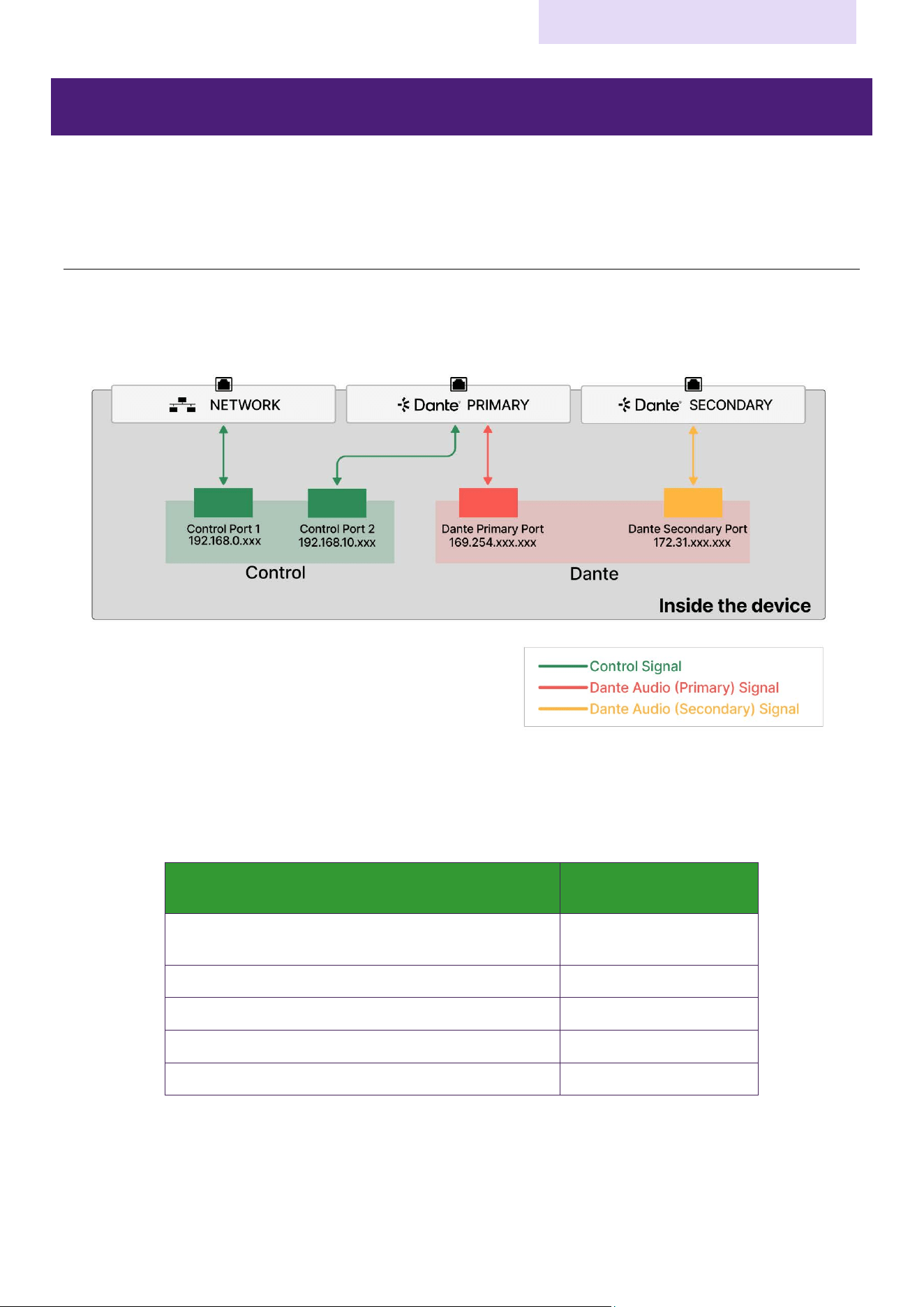
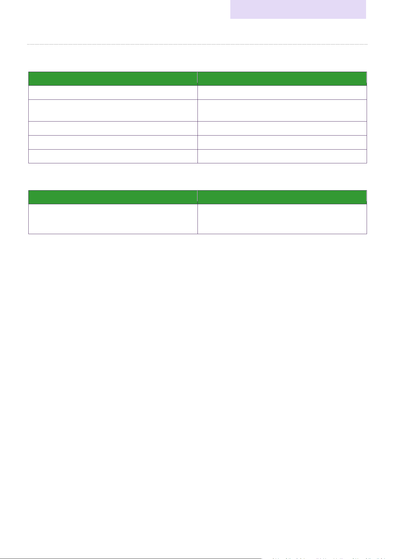
In this document, the network configuration of each product is described using illustrations and tables similar to the
ones below. This section explains the illustrations and tables.
The diagram above is a simplified diagram of the device's internal network configuration. It shows the signal flow
from the NETWORK connector, Dante PRIMARY connector, and Dante SECONDARY connector. Green squares
represent network interfaces used to control peripheral devices and from controllers. The red square represents
Dante Primary network interface, and the yellow square represents Dante Secondary network interfaces.
Control Application
Maximum Number of
Connections
ProVisionaire Kiosk
3rd Party Device
64
OSC
8
ADM-OSC
8
ProVisionaire Design
1
Sound xR Image Controller
10
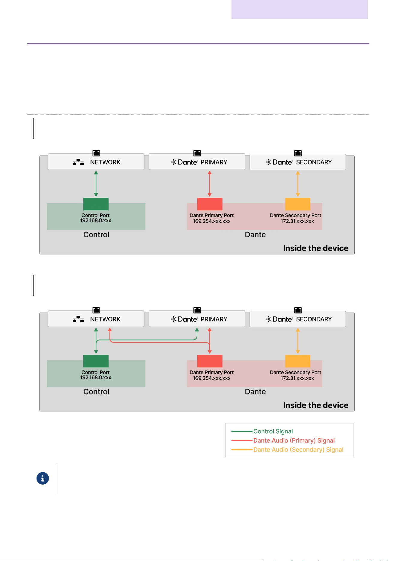
The table above shows the maximum number of connections per communication protocol. This indicates the
maximum number of communications that a single device can receive via each control application. In the above
example, for one device, a total of 64 units can be connected via ProVisionaire Kiosk and 3rd Party Device, and can
be controllable.
Network Configuration
Setup Guide (Network)
5
Device List
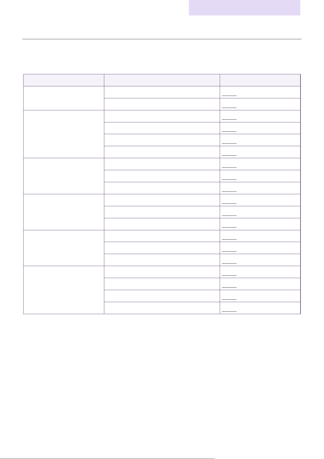
The products described in this document are listed below.
*This document contains information only about products related to the New CIS Ecosystem.
Category
Product Number
Network Specifications Link
Processor
DME3, DME5
Type2
DME7, DME10
Type1
Power amplifier
XMS series (Standard model)
Type6
XMS series (Dante model)
Type2
XMV series (Standard model)
Type6
XMV series (Dante model)
Type3
Interface
Rio3224-D3, Rio1608-D3
Type1
RUio1608SB-D, RUio0804-D, RUio16FLX-D
Type1
Tio1608-D2
Type3
Speaker
VXC2P
Type4
VXL1-16P
Type4
DZR series (Dante model)
Type5
Microphone
RM-CG
Type4
RM-TT
Type4
RM-WAP-16, RM-WAP-8
Type4
Control Hardware
MCP2
Type6
MCP1
Type6
CTL-BN1
Type6
TCD10
Type6
Network Configuration
Setup Guide (Network)
6
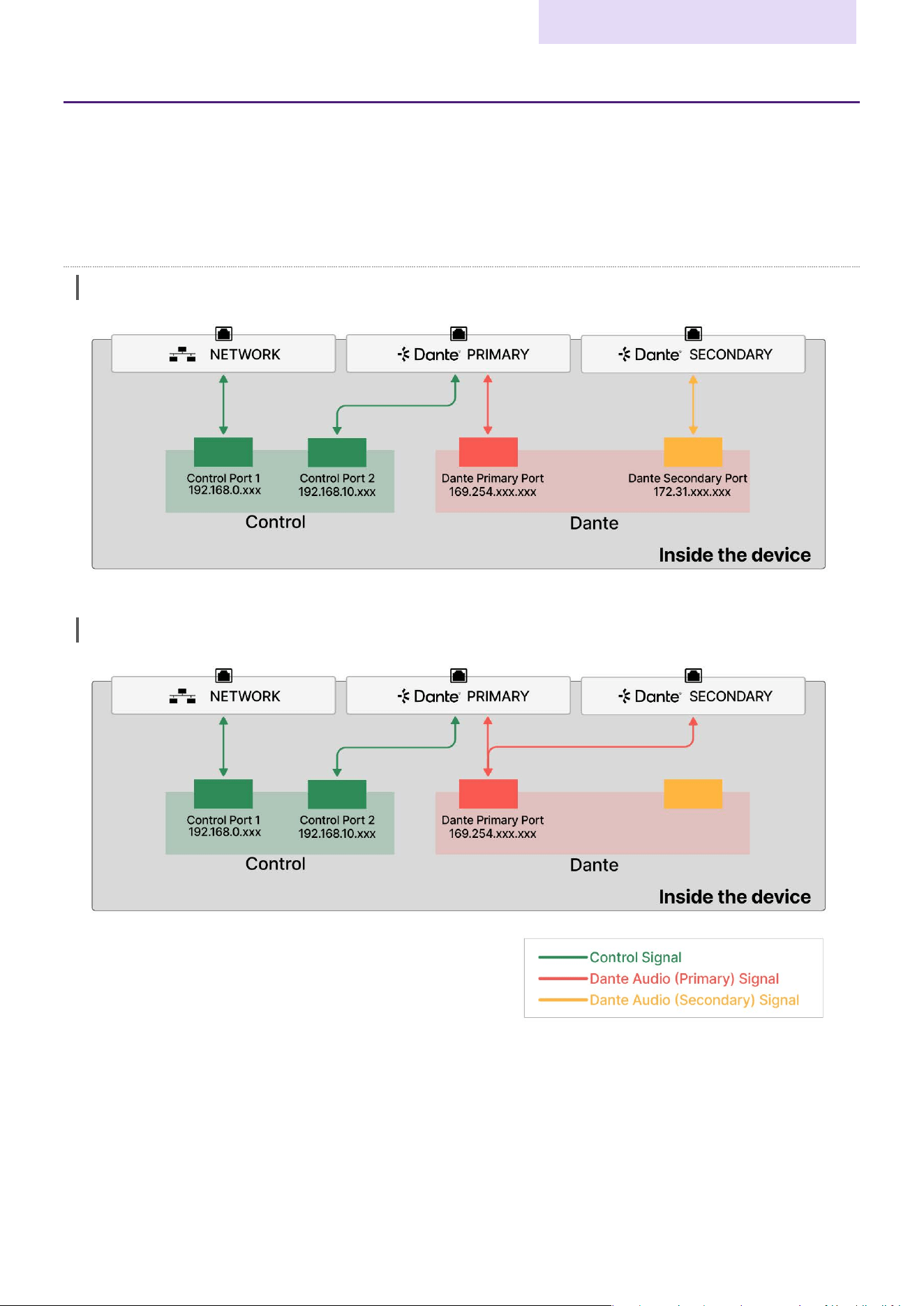
Type1 (Network, Dante Pri., Dante Sec.)
Applicable Products: DME10, DME7, Rio3224-D3, Rio1608-D3, RUio1608SB-D, RUio0804-D, RUio16FLX-D
Physical Network Connectors: NETWORK connector, Dante PRIMARY connector, Dante SECONDARY connector
Number of Control Network Interfaces: 2
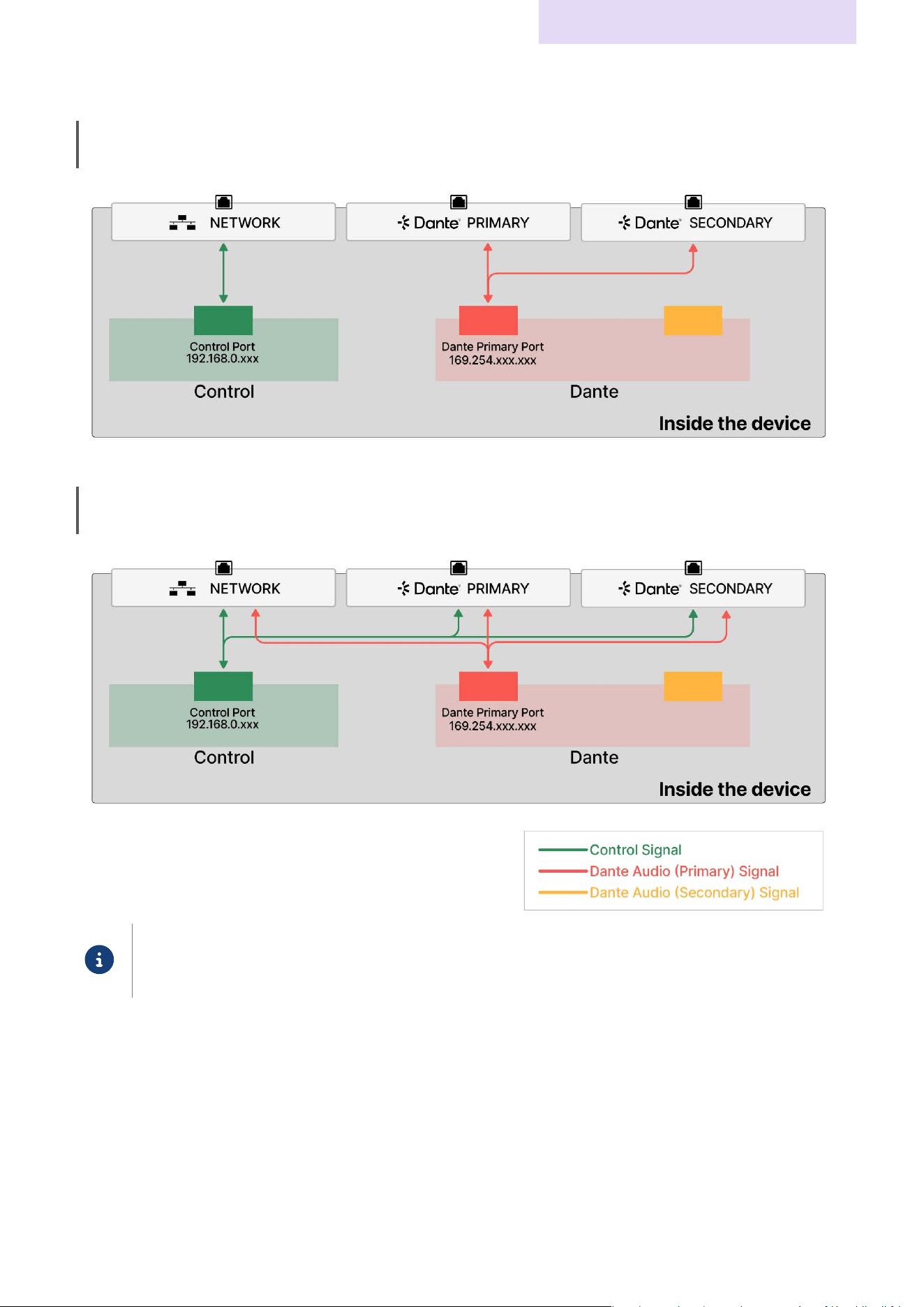
Internal Network Configuration
Redundant
Daisy Chain
Network Configuration
Setup Guide (Network)
7
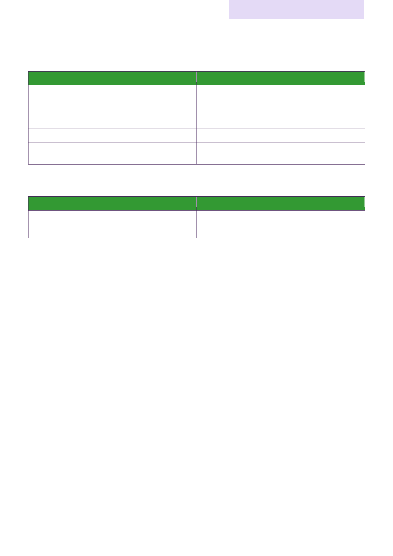
Maximum Number of Connections for Each Application
■DME10, DME7
Control Application
Maximum Number of Connections
ProVisionaire Design
1
ProVisionaire Kiosk
3rd Party Device
64
OSC
8
ADM-OSC
8
Sound xR Image Controller
10
■Rio3224-D3, Rio1608-D3, RUio1608SB-D, RUio0804-D, RUio16FLX-D
Control Application
Maximum Number of Connections
ProVisionaire Design
ProVisionaire Kiosk
R-Remote
6
Network Configuration
Setup Guide (Network)
8
Type2 (Network, Dante Pri., Dante Sec.)
Applicable Products: DME5, DME3, XMS series (Dante model)
Physical Network Connectors: NETWORK connector, Dante PRIMARY connector, Dante SECONDARY connector
Number of Control Network Interfaces: 1
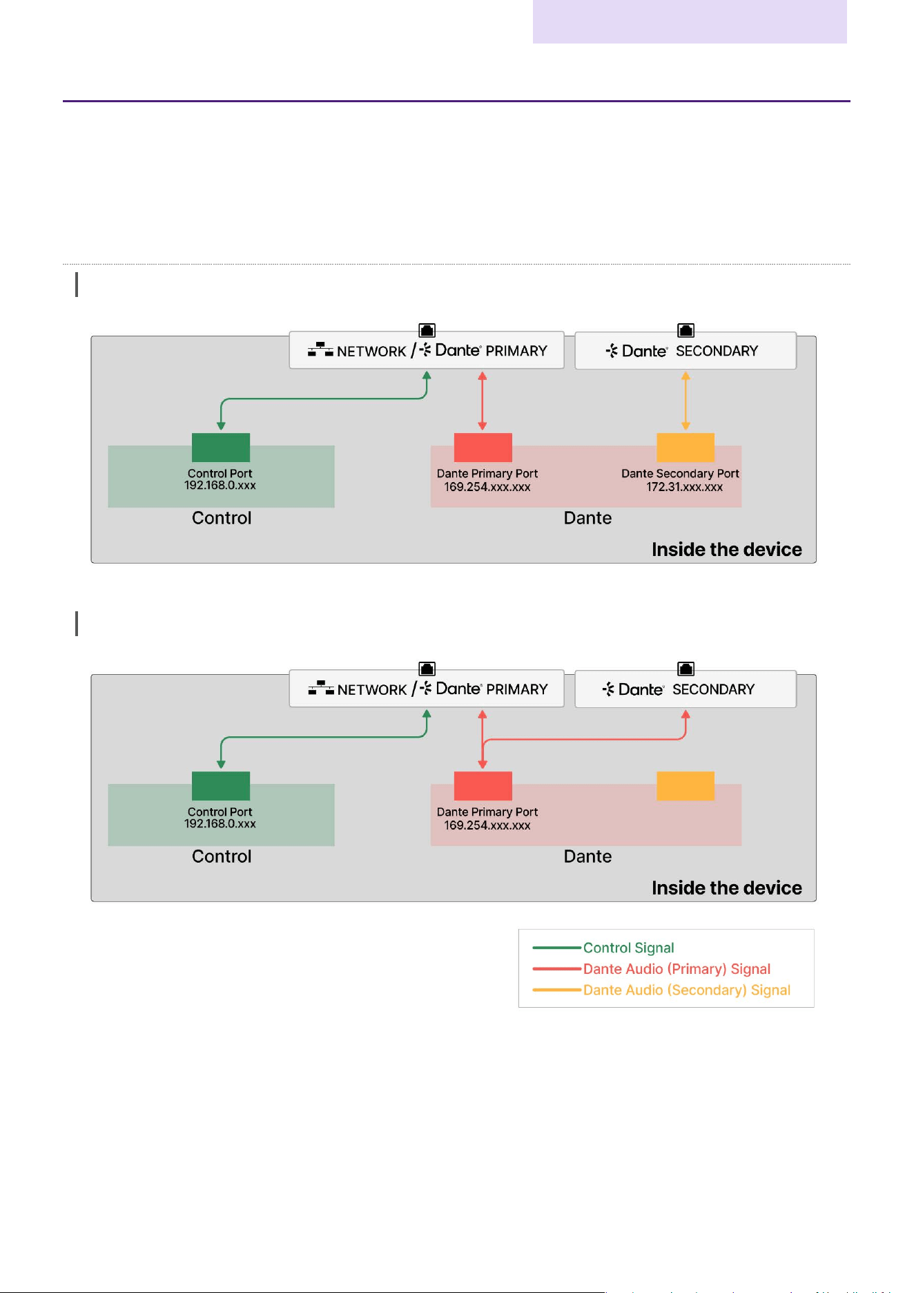
Internal Network Configuration
Redundant
When “Control Separated” is selected:
Redundant
When “Control Merged” is selected:
When “Control Merged” is selected, the NETWORK and Dante PRIMARY connectors are internally
connected to each other and perform the same function. Take care when making connections to avoid
network loops.
Network Configuration
Setup Guide (Network)
9
Daisy Chain
When “Control Separated” is selected:
Daisy Chain
When “Control Merged” is selected:
When “Control Merged” is selected, the NETWORK , Dante PRIMARY, and Dante SECONDARY
connectors are internally connected to each other, and perform the same function. Take care when
making connections to avoid network loops.
Network Configuration
Setup Guide (Network)
10
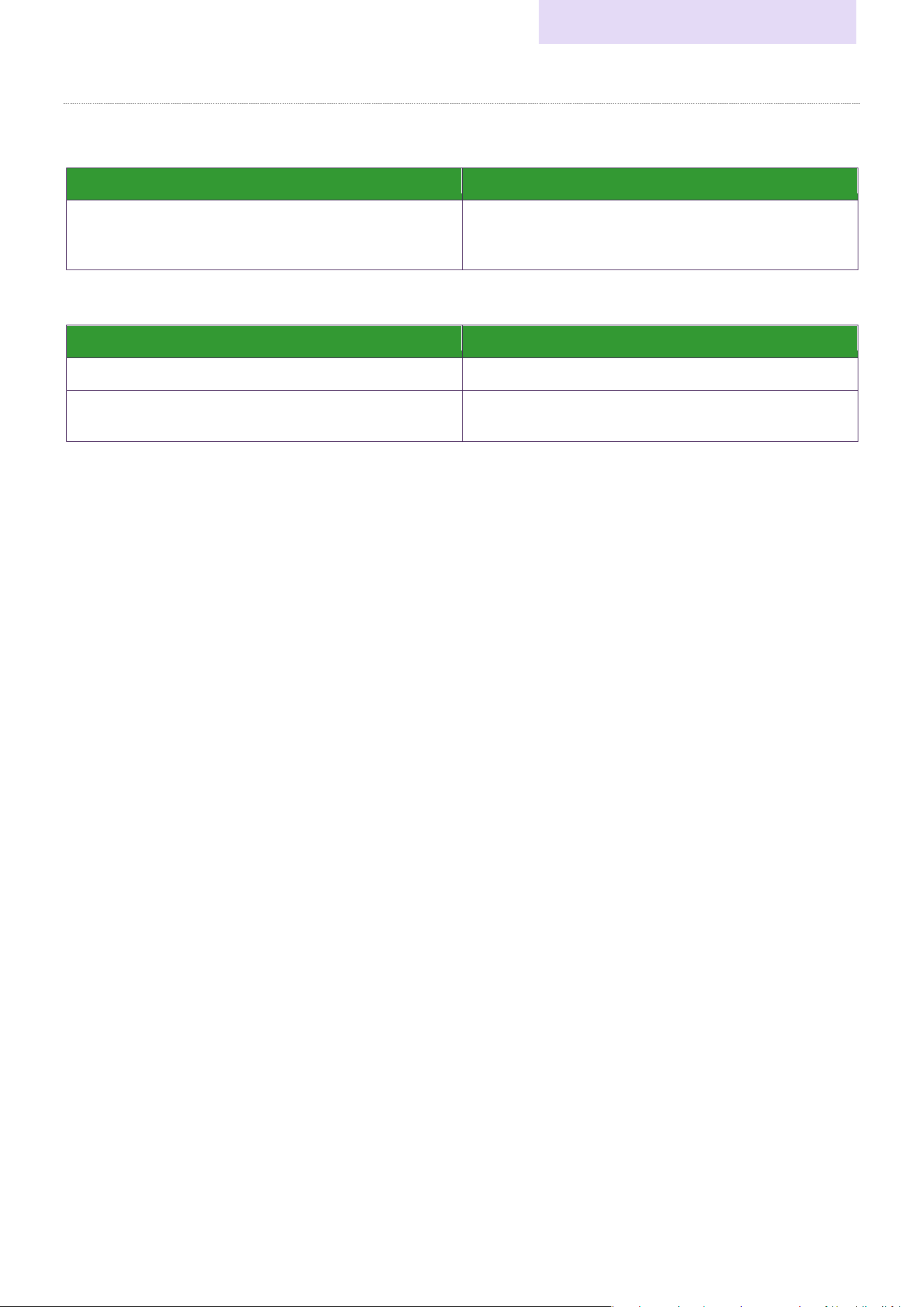
Maximum Number of Connections for Each Application
■DME5, DME3
Control Application
Maximum Number of Connections
ProVisionaire Design
1
ProVisionaire Kiosk
MCP2
3rd Party Device
64
OSC
8
TCD10 / PC Web Browser
(for Custom Control Panel)
No limitations *
1
*1 There are no theoretical limitations, but we cannot guarantee operation in actual usage environments.
■XMS series (Dante model)
Control Application
Maximum Number of Connections
ProVisionaire Design
1
ProVisionaire Kiosk
8
Network Configuration
Setup Guide (Network)
11
Type3 (Network/Dante Pri., Dante Sec.)
Applicable Products: Tio1608-D2, XMV series (Dante model)
Physical Network Connectors: NETWORK/Dante PRIMARY connector, Dante SECONDARY connector
Number of Control Network Interfaces: 1
Internal Network Configuration
Redundant
Daisy Chain
Network Configuration
Setup Guide (Network)
12
Maximum Number of Connections for Each Application
■Tio1608-D2
Control Application
Maximum Number of Connections
ProVisionaire Design
ProVisionaire Kiosk
R-Remote
6
■XMV series (Dante model)
Control Application
Maximum Number of Connections
ProVisionaire Design
1
ProVisionaire Kiosk
3rd Party Device
8
Network Configuration
Setup Guide (Network)
13
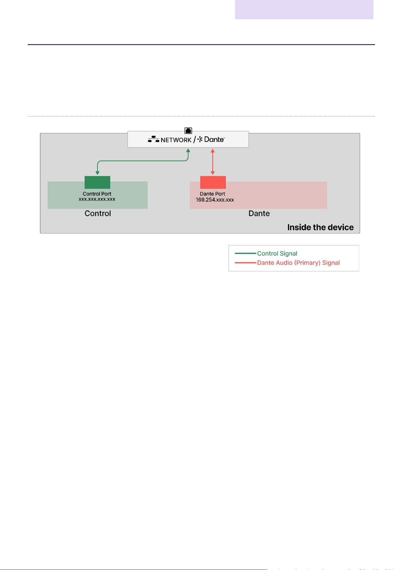
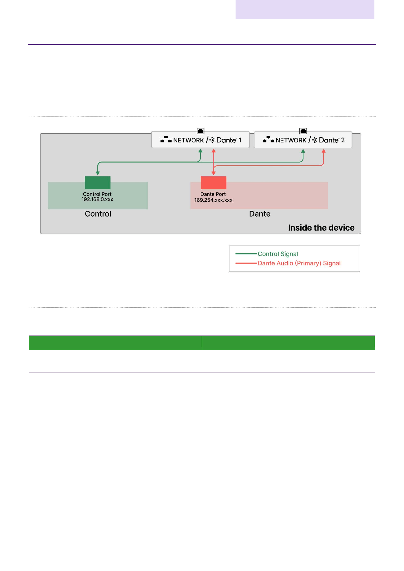
Type4 (Network/Dante)
Applicable Products: VXL1-16P, VXC2P, RM-CG, RM-TT, RM-WAP-16, RM-WAP-8
Physical Network Connectors: NETWORK/Dante connectors
Number of Control Network Interfaces: 1
Internal Network Configuration
Network Configuration
Setup Guide (Network)
14
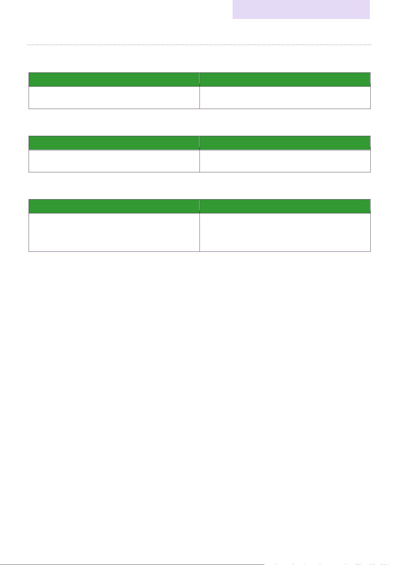
Maximum Number of Connections for Each Application
■VXL1-16P, VXC2P
Control Application
Maximum Number of Connections
ProVisionaire Design
ProVisionaire Kiosk
5
■RM-CG, RM-TT
Control Application
Maximum Number of Connections
ProVisionaire Design
ProVisionaire Kiosk
8
■RM-WAP-16, RM-WAP-8
Control Application
Maximum Number of Connections
ProVisionaire Design
ProVisionaire Kiosk
3
rd
Party Device
(Q-SYS Plug In, AMX, Crestron etc.)
8
Network Configuration
Setup Guide (Network)
15
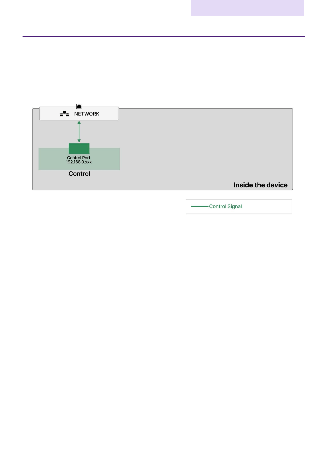
Type5 (Network/Dante1, Network/Dante2)
Applicable Products: DZR series (Dante model)
Physical Network Connectors: NETWORK/Dante1 connector, NETWORK/Dante2 connector
Number of Control Network Interfaces: 1
Internal Network Configuration
Maximum Number of Connections for Each Application
■DZR series (Dante model)
Control Application
Maximum Number of Connections
ProVisionaire Design
ProVisionaire Kiosk
5
Network Configuration
Setup Guide (Network)
16
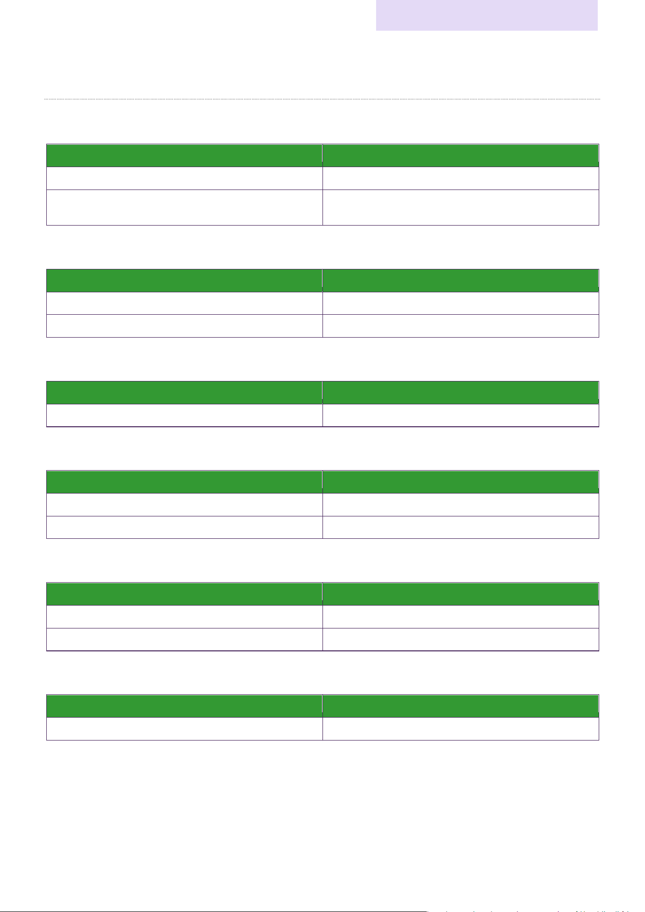
Type6 (Network)
Applicable Products: XMV series (Standard model), XMS series (Standard model), CTL-BN1, MCP1, MCP2, TCD10
Physical Network Connectors: NETWORK connector
Number of Control Network Interfaces: 1
Internal Network Configuration
Network Configuration
Setup Guide (Network)
17
Maximum Number of Connections for Each Application
■XMV series (Standard model)
Control Application
Maximum Number of Connections
ProVisionaire Design
1
ProVisionaire Kiosk
3rd Party Device
8
■XMS series (Standard model)
Control Application
Maximum Number of Connections
ProVisionaire Design
1
ProVisionaire Kiosk
8
■CTL-BN1
Control Application
Maximum Number of Connections
ProVisionaire Design
1
■MCP1
Control Application
Maximum Number of Connections
ProVisionaire Design
1
3rd Party Device (AMX, Crestron, etc.)
8
■MCP2
Control Application
Maximum Number of Connections
ProVisionaire Design
1
3rd Party Device (AMX, Crestron, etc.)
5
■TCD10
Control Application
Maximum Number of Connections
TCD Manager
1

IP Address Assignment
Setup Guide (Network)
18
IP Address Assignment
Control IP Address Assignment
The IP addresses used to control Yamaha network devices are as follows. For more information on how to set IP
addresses, refer to the respective product manuals.
• Automatic assignment
‐
DHCP
If the network features a DHCP server, the IP address will be assigned to the device automatically.
‐
Auto IP
If the network does not feature a DHCP server, the device will automatically assign a link-local address.
• Manual assignment
‐ Unit ID
The Unit ID value is used as the IP address. The Unit ID is the fourth octet of the IP Address
(192.168.0.Unit ID). You can set the Unit ID using the hardware DIP switches or rotary switches, the
device's screen, ProVisionaire Design, etc.
‐ Manual
You can set the IP address as you wish.
Dante IP Address Assignment
The IP addresses for Dante are as follows. Use Audinate's Dante Controller to assign them. For more information,
refer to the Audinate website.
• Automatic assignment
If the network features a DHCP server, the IP address will be assigned automatically.
If your network does not feature a DHCP server, link-local addresses (Primary IP 169.254.x.x/16, Secondary IP
172.31.x.x/16) will be automatically assigned.
• Manual assignment
You can also assign the IP addresses manually.

IP Address Assignment
Setup Guide (Network)
19
Control IP Address Assignment List
The IP address assignment used to control each device is as follows.
* This document contains information only about products related to the New CIS Ecosystem.
Category Model
Automatic
Manual
Default
DHCP
Auto IP
Unit ID
Manual
Processor
DME5, DME3
✓
✓
✓
✓
Automatic*
1
DME10, DME7
✓
*
2
✓
✓
Unit ID
Power
amplifier
XMS series
✓
✓
✓
✓
Automatic*
1
XMV series
(Standard model)
✓
✓
✓
Unit ID
XMV series
(Dante model)
✓
✓
✓
Unit ID
Interface
Rio3224-D3, Rio1608-D3
✓
✓
✓
Manual or
Automatic*
3
RUio1608SB-D, RUio0804-
D, RUio16FLX-D
✓
✓
✓
Manual or
Automatic*
3
Tio1608-D2
✓
✓
✓
Auto IP
Speaker
VXC2P
✓
✓*
4
✓
✓
Unit ID
VXL1-16P
✓
✓*
4
✓
✓
Unit ID
DZR series (Dante model)
✓
✓
✓
✓
Automatic*
1
Microphone
RM-CG
✓
✓
✓
Automatic*
1
RM-TT
✓
✓
✓
Automatic*
1
RM-WAP-16, RM-WAP-8
✓
✓
✓
Automatic*
1
Control
Hardware
MCP1
✓
✓
✓
✓
Unit ID
MCP2
✓
✓
✓
Automatic*
1
CTL-BN1
✓
✓
✓
Automatic*
1
TCD10
✓
✓
✓
Automatic*
1
*1: If a DHCP server is present on the same network, it will use DHCP; if not, it will use Auto IP.
*2: Control Port 1 (NETWORK connector) does not support Auto IP, while Control Port 2 (Dante Primary
connector) does.
*3: Control Port 1 (NETWORK connector) uses Manual [192.168.0.2], and Control Port 2 (Dante Primary
connector) uses DHCP/Auto IP.
*4: When using VXL1-16P and VXC2P in IP address auto-assignment mode (PC mode), set DIP switch 6
to OFF and restart the device.
IP Address Assignment
Setup Guide (Network)
20
Network Connection Method
This section explains how to connect factory-shipped devices to the control network and enable communication via
ProVisionaire Design.
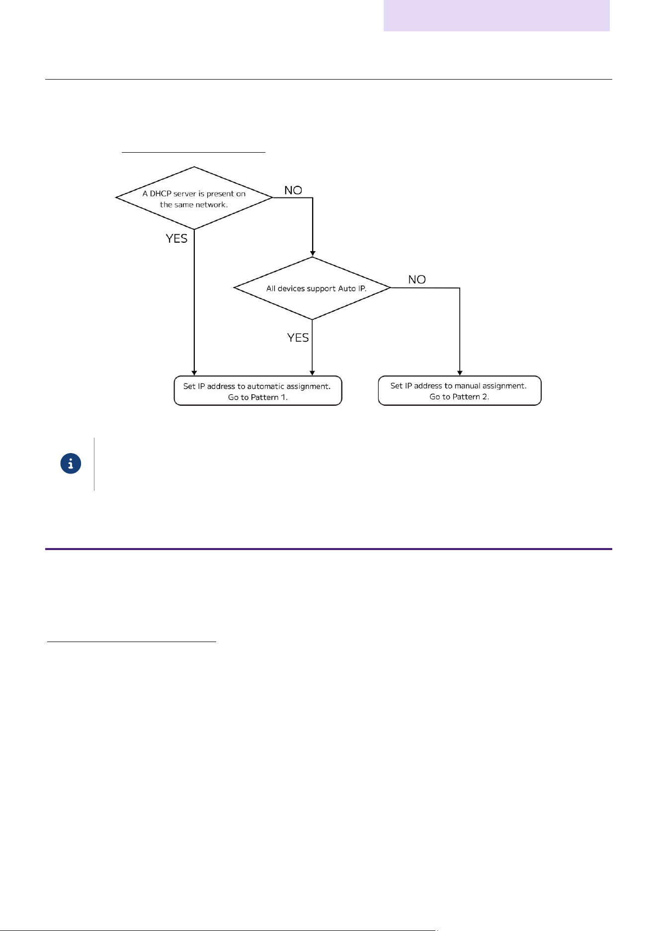
First, follow the flow chart below to check the system specifications. To find out whether your device supports Auto
IP, refer to the “IP Address Assignment List.”
All devices listed in this manual, except for the XMV series, support Auto IP. If a DHCP server is present
on the network, or if the system is configured using only Auto IP compatible devices, we recommend that
you use automatic IP address assignment.
Pattern 1
If a DHCP server is present or all devices support Auto IP
IP address auto-assignment will be applied, and the IP addresses of all devices will be automatically set to the same
network. Simply connect devices to the same network using the following procedure to set up communication with
ProVisionaire Design without manual assignment.
Network connection procedure
1.
If any devices have their default IP address assignments set to manual mode, change them to automatic mode
and restart the devices.
You can switch modes using the device's DIP switches, etc. For more information, refer to the manual for each
device.
2.
Set the PC's IP address to automatic assignment.
3.
Connect all devices, the PC, and the DHCP server (if any) to the network.
4.
Launch ProVisionaire Design.
5.
In the “Network Setup” dialog, select the checkbox for the network card that will communicate with the
devices, and then click the [OK] button.
When the file selection dialog appears, click [X] to close the screen.
6.
Make sure that all devices are displayed in the network area of ProVisionaire Design.
7.
Assign unique Unit IDs in ProVisionaire Design.
This completes the connection setup.

IP Address Assignment
Setup Guide (Network)
21
Pattern 2
If a DHCP server is not present, and some devices do not support Auto IP
You must manually set the IP addresses of all devices to static IP addresses.
For a smoother connection, first connect Auto IP-compatible devices to ProVisionaire Design with their IP addresses
set to Auto IP, change them to static IP addresses, and then connect non-Auto IP-compatible devices.
Network connection procedure
1.
Set the PC's IP address to automatic assignment.
2.
Connect the Auto IP-compatible devices and the PC to the network.
Do not connect non-Auto IP-compatible devices yet.
3.
Launch ProVisionaire Design.
4.
In the “Network Setup” dialog, select the checkbox for the network card that will communicate with the
devices, and then click the [OK] button.
When the file selection dialog appears, click [X] to close the screen.
5.
Make sure that the devices are displayed in the network area of ProVisionaire Design.
6.
In ProVisionaire Design, go to System menu > IP Settings > IP Address and set the IP address of each device
to a fixed IP address [192.168.0.xxx/255.255.255.0].
Be careful not to duplicate IP addresses.
You can also use a function in ProVisionaire Design to set fixed IP addresses all at once. For more
information, refer to the “Auto-Assign IP Addresses dialog box” section in the “Provisionaire
Design User Guide.”
7.
After changing the IP addresses, restart the device to apply the changes.
8.
Set the PC's IP address to a fixed IP address [192.168.0.xxx/255.255.255.0].
9.
Set a device that does not support Auto IP to Unit ID mode, and then set the Unit ID.
The device's IP address will be set to “192.168.0.Unit ID/255.255.255.0”.
You can switch modes and set the Unit IDs using the device's DIP switches or on the device's screen. For more
information, refer to the manual for each device.
Be careful not to duplicate the IP address of another device that you have already set in step 7.
10.
Connect the non-Auto IP-compatible devices to the network.
11.
Make sure that all devices are displayed in the network area of ProVisionaire Design.
This completes the connection setup.

© 2026 Yamaha Corporation
Published: 09/2026
YJ-C0