
LAUNCH
i
Copyright Information
Copyright © 2024 by LAUNCH TECH CO., LTD. All rights reserved. No part of this publication may be
reproduced, stored in a retrieval system, or transmitted in any form or by any means, electronic,
mechanical, photocopying, recording or otherwise, without the prior written permission of LAUNCH.
The information contained herein is designed only for the use of this unit. LAUNCH is not responsible
for any use of this information as applied to other units.
Important Safety Information
Warning: To avoid personal injury, property damage, or accidental damage to the product, read all of
the information in this section before using the product.
Work Area Safety
Keep work area clean and well lit. Cluttered benches and dark areas may cause accidents.
Do not connect or disconnect the tool while the ignition is on or the engine is running.
DO NOT attempt to operate the tool while driving the vehicle. Have a second person to operate the
tool.
Before testing a vehicle, put the transmission in PARK (for automatic transmission) or NEUTRAL (for
manual transmission). Engage the parking brake and chock the tires.
NEVER smoke or allow a spark or flame in vicinity of battery or engine.
The vehicle shall be tested in a well-ventilated work area, as engines produce various poisonous
compounds (hydrocarbon, carbon monoxide, nitrogen oxides, etc.)
Do not operate the tool in explosive atmospheres, such as in the presence of flammable liquids,
gases, or heavy dust.
Never leave the vehicle unattended while testing.
Keep a fire extinguisher suitable for gasoline/chemical/electrical fires nearby.
Use extreme caution when working around the ignition coil, distributor cap, ignition wires and spark
plugs. These components create hazardous voltages when the engine is running.
Keep bystanders, children and visitors away while operating the tool.
This product is not a toy. Do not allow children to play with or near this tool.
Use as intended only. Do not modify.
Inspect before every use; do not use if parts are loose or damaged.
Do not place the tool on any unstable surface.
Handle the tool with care. If the tool is dropped, check for breakage and any other conditions that
may affect its operation.
Keep the tool dry, clean, free from oil, water or grease. Use a mild detergent on a clean cloth to clean
the outside of the tool when necessary.
Store the tool and accessories in a locked area out of the reach of children.
To avoid damaging the tool or generating false data, please make sure the vehicle battery is fully
charged and the connection to the vehicle DLC (Data Link Connector) is clear and secure.
If the VCI (Vehicle Communication Interface) is not in use for a long period of time, it is suggested to
unplug the VCI from vehicle’s DLC to conserve battery power.
Electrical Safety

LAUNCH
ii
Do not use the tool while standing in water.
Avoid body contact with grounded surfaces such as pipes, radiators, ranges and refrigerators.
Do not expose the tool or power adaptor to rain or wet conditions. Water entering the tool or
power adaptor increases the risk of electric shock.
Personal Safety
Wear an ANSI-approved eye shield when testing or repairing vehicles.
Do not wear loose clothing or jewelry. Keep hair, clothing, hands, tools, and test equipment away
from moving or hot engine parts. Loose clothes, jewelry, or long hair can be caught in moving parts.
Do not use the tool while tired or under the influence of drugs, alcohol, or medications. A moment of
interruption can result in serious personal injury.
People with pacemakers should consult their physician(s) before use. Electromagnetic fields in close
proximity to heart pacemaker could cause pacemaker interference or pacemaker failure.
The warnings, precautions, and instructions discussed in this instruction manual cannot cover all
possible conditions and situations that may occur. It must be understood by the operator that
common sense and caution are factors which cannot be built into this product, but must be supplied
by the operator.
There are no user serviceable parts. Have the tool serviced by a qualified repair person using only
identical replacement parts. This will ensure that the safety of the equipment is maintained.
Please use the included battery and charger. Risk of explosion if the battery is replaced with an
incorrect type.
Automotive batteries contain sulfuric acid that is harmful to skin. In operation, direct contact with the
automotive batteries should be avoided. Keep the ignition sources away from the battery at all times.
Precautions on Operating Vehicle’s ECU
Do not disconnect battery or any wiring cables in the vehicle when the ignition switch is on, as this
could avoid damage to the sensors or the ECU.
Do not place any magnetic objects near the ECU. Disconnect the power supply to the ECU before
performing any welding operations on the vehicle.
Use extreme caution when performing any operations near the ECU or sensors. Ground yourself
when you disassemble PROM, otherwise ECU and sensors can be damaged by static electricity.
When reconnecting the ECU harness connector, be sure it is attached firmly, otherwise electronic
elements, such as ICs inside the ECU, can be damaged.

LAUNCH
iii
Compliance Information
FCC ID: XUJX431PROV5
IC: 29886-PO1005A
Any changes or modifications not expressly approved by the party responsible for compliance could
void the user’s authority to operate the equipment.
This device complies with Part 15 of the FCC Rules. Operation is subject to the following two
conditions:
(1) This device may not cause harmful interference, and
(2) This device must accept any interference received, including interference that may cause undesired
operation.
Note: This equipment has been tested and found to comply with the limits for a Class B digital device,
pursuant to part 15 of the FCC Rules. These limits are designed to provide reasonable protection
against harmful interference in a residential installation. This equipment generates, uses and can
radiate radio frequency energy and, if not installed and used in accordance with the instructions, may
cause harmful interference to radio communications. However, there is no guarantee that interference
will not occur in a particular installation. If this equipment does cause harmful interference to radio or
television reception, which can be determined by turning the equipment off and on, the user is
encouraged to try to correct the interference by one or more of the following measures:
- Reorient or relocate the receiving antenna.
- Increase the separation between the equipment and receiver.
- Connect the equipment into an outlet on a circuit different from that to which the receiver is connected.
- Consult the dealer or an experienced radio/TV technician for help.
This device contains licence-exempt transmitter(s) that comply with Innovation, Science and Economic
Development Canada's licence-exempt RSS(s). Operation is subject to the following two conditions:
(1) This device may not cause interference.
(2) This device must accept any interference, including interference that may cause undesired
operation of the device.
Le present appareil est conforme aux CNR d'Industrie Canada applicables aux appareils radio exempts
de licence. L'exploitation est autorisee aux deux conditions suivantes:
(1) l'appareil ne doit pas produire de brouillage, et
(2) Iutilisateur de l'appareil doit accepter tout brouillage radioelectrique subi, meme si le broullage est
susceptible d'en compromettre le fonctionnement.
The device and the distance from the human body during normal use is 0mm, RF exposure limit is 1.6
W/Kg. The device has been evaluated to meet general RF exposure requirement. The highest reported
SAR is below the maximum value.
We declare that this device is in compliance with the essential requirements and other relevant
provisions of Radio Equipment Directive 2014/53/EU.

LAUNCH
IV
TABLE OF CONTENTS
1 Introduction ....................................................................................................................................................... 1
1.1 Product Profile .............................................................................................................................. 1
1.2 Package List ................................................................................................................................. 1
1.3 Components & Controls................................................................................................................. 2
1.3.1 Display Tablet ....................................................................................................................................... 2
1.3.2 SmartLink C V2.0 Device ...................................................................................................................... 4
1.4 Technical Parameters .................................................................................................................... 5
2 Initial Use ........................................................................................................................................................... 6
2.1 Charging & Turning On .................................................................................................................. 6
2.2 Screen Layout ............................................................................................................................... 6
2.3 Adjust Brightness .......................................................................................................................... 6
2.4 Change System Language ............................................................................................................ 6
2.5 Set Standby Time .......................................................................................................................... 6
2.6 WLAN Setup ................................................................................................................................. 7
3 Register & Update ............................................................................................................................................. 8
3.1 Register & Update ......................................................................................................................... 8
3.2 Job Menu ...................................................................................................................................... 9
4 Connections ...................................................................................................................................................... 11
4.1 Preparation ................................................................................................................................... 11
4.2 Vehicle Connection ....................................................................................................................... 11
4.3 Communication Setup ................................................................................................................... 12
5 Diagnosis ........................................................................................................................................................... 13
5.1 Intelligent Diagnose ....................................................................................................................... 13
5.2 Local Diagnose ............................................................................................................................. 15
5.3 Remote Diagnose ......................................................................................................................... 21
5.3.1 SmartLink Super Remote Diagnostics .................................................................................................. 21
5.3.2 X431 Remote Diagnostics .................................................................................................................... 23
5.4 EV (Electric Vehicle) Diagnose ...................................................................................................... 28
5.4.1 Vehicle Diagnosis ................................................................................................................................. 28
5.4.2 Battery Pack Detection ......................................................................................................................... 29
5.5 Feedback ...................................................................................................................................... 30
5.6 Diagnostic History ......................................................................................................................... 30
6 Service Function (Reset) .................................................................................................................................. 32
7 Software Update ................................................................................................................................................ 33
7.1 Update Diagnostic Software & APP................................................................................................ 33
7.2 Update Frequently Used software .................................................................................................. 33
7.3 Renew Subscription ...................................................................................................................... 34
8 Toolbox .............................................................................................................................................................. 35
8.1 TPMS ........................................................................................................................................... 35
8.2 ADAS (Calibration) ........................................................................................................................ 35

LAUNCH
V
8.3 Oscilloscope ................................................................................................................................. 35
8.4 Sensor Simulator ........................................................................................................................... 35
8.5 Videoscope ................................................................................................................................... 35
8.6 BST360 (Battery Tester) ................................................................................................................ 35
8.7 Multimeter ..................................................................................................................................... 36
8.8 Current Clamp ............................................................................................................................... 36
8.9 Insulation Tester............................................................................................................................ 36
8.10 Immobilizer Programmer.............................................................................................................. 36
8.11 Key Programmer ......................................................................................................................... 36
9 Diagnostic Widget ............................................................................................................................................. 37
9.1 Vehicle Coverage .......................................................................................................................... 37
9.2 CAN Bus Pin Detection.................................................................................................................. 37
9.3 CANScope .................................................................................................................................... 37
9.4 Diagnostic Software Clear ............................................................................................................. 37
9.5 Fix Connector Firmware/System .................................................................................................... 37
9.6 Data Stream Sample ..................................................................................................................... 37
9.7 DLC Voltage Check ....................................................................................................................... 37
9.8 Reset MSVIN ................................................................................................................................ 37
9.9 Diagnostic History ......................................................................................................................... 37
10 User Info........................................................................................................................................................... 38
10.1 My Report ................................................................................................................................... 38
10.2 VCI ............................................................................................................................................. 38
10.3 Activate VCI ................................................................................................................................ 38
10.4 Profile ......................................................................................................................................... 38
10.5 My Order ..................................................................................................................................... 38
10.6 Change Password ....................................................................................................................... 38
10.7 Login/Log out .............................................................................................................................. 38
11 Settings ............................................................................................................................................................ 39
11.1 Units ........................................................................................................................................... 39
11.2 Shop information ......................................................................................................................... 39
11.3 Printer set ................................................................................................................................... 39
11.4 Clear cache ................................................................................................................................. 40
11.5 Diagnostic software auto update .................................................................................................. 40
11.6 Device account management ....................................................................................................... 40
12 J2534 Reprogramming .................................................................................................................................... 42
13 FAQ ................................................................................................................................................................... 43
13.1 About diagnostic tablet ................................................................................................................ 43
13.2 About SmartLink Diag. ................................................................................................................. 44
Warranty ................................................................................................................................................................ 45

LAUNCH
1
1 Introduction
1.1 Product Profile
It inherits from LAUNCH’s advanced diagnosing technology and is characterized by covering a wide
range of vehicles, featuring powerful functions, and providing precise test result.
It has the following features: Intelligent Diagnose, Local Diagnose, EV (Electric Vehicle) Diagnose &
Service, SmartLink Super Remote Diagnose, X431 Remote Diagnose, Service Function, Toolbox,
Software Update, Feedback, Online Mall and Diagnostic History etc.
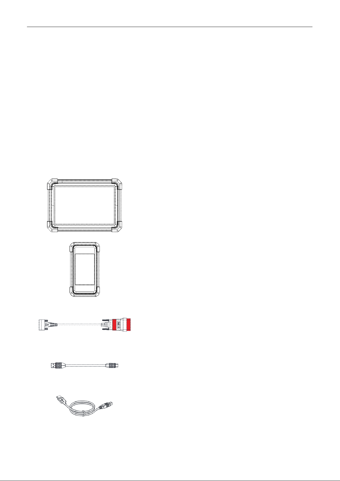
1.2 Package List
Common accessories are same, but for different destinations, the accessories (such as diagnostic
software, testing connectors) may vary. Please consult from the seller or check the package list
supplied with this tool together.
Display tablet x 1
Indicates the test result.
SmartLink C V2.0 device x 1
Collects vehicle data and sends it to the tablet for analysis.
Diagnostic cable x 1
Connects the SmartLink C device to the OBD II vehicle’s
DLC.
Data cable (Type A-Type C) x 1
Connects the tablet to a PC for data exchange/charging.
Data cable (Type A-Type B) x 1
Connects the SmartLink C device to PC for J2534
reprogramming/Connects the SmartLink C device to
diagnostic tablet to perform vehicle diagnosis.

LAUNCH
2
Crossover cable x 1
Connects the SmartLink C device to the modem.
Password envelope x 1
A piece of paper bearing the product Serial Number and
Activation Code for product registration.
Quick start guide x 1
Power adaptor x 1 + switching adaptor x 2
Charges the tablet via the AC outlet.
Non
-
16pin adaptor kit for passenger cars (optional)
For different vehicle diagnostic socket, it may be necessary
to use one of the non-16pin connectors included within the
kit.
For detailed non-16pin connectors, please check the
package box.
1.3 Components & Controls
There are two main components to the diagnostic system:
Display Tablet – the central processor and monitor for the system (See Chapter 1.3.1).
SmartLink C V2.0 Device – the device for accessing vehicle data (See Chapter 1.3.2).
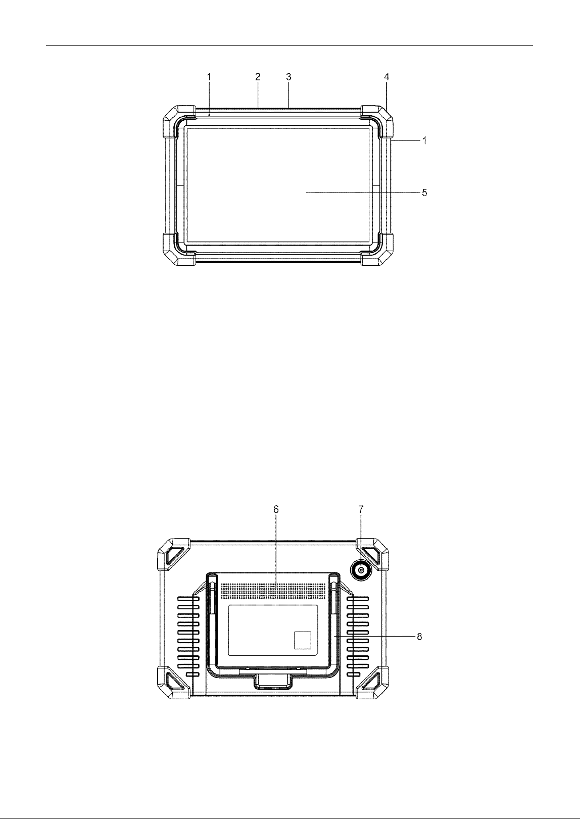
1.3.1 Display Tablet
The tablet acts as the central processing system, which is used to receive and analyze the live vehicle
data from the SmartLink C device and then output the test result.
LAUNCH
3
1. Microphone
2. Type-A USB Port
• Connect to the SmartLink C device to perform vehicle diagnosis via the USB cable.
• Connect to compatible add-on modules (such as Videoscope) or USB storage devices.
3. Type-C USB Port
• Connect to AC outlet for charging.
• Connect to PC for data exchange.
4. POWER Key
Turn the tablet on/off.
Note: Press and hold it for 8 seconds to perform forced shutdown.
5. LCD Screen
Indicate the test result.
6. Speakers
7. Rear Camera
8. Adjustable stand
LAUNCH
4
Flip it out to any angle and work comfortable at your desk, or hang it on steering wheel.
1.3.2 SmartLink C V2.0 Device
The SmartLink C V2.0 device features powerful functions and it can be applied in the following
situations:
1). When as a VCI (Vehicle Communication Interface), it needs to work in conjunction with the
Diagnose module of the tablet, which is used to obtain vehicle data, and then send it to the tablet
for analysis wirelessly or via data cable.
2). When as a SmartLink C (Customer) dongle, it does not communicate with the tablet, but it needs to
work together with the SmartLink module of the tablet. The tablet is mainly used to issue remote
diagnostic requests, and the SmartLink C dongle is networked to receive and execute commands
from the remote SmartLink B (Business).
Note: For detailed operations, please refer to Chapter 5.3.1.
3). When as a local J2534 PassThru device, it can be used in conjunction with the PC installed with
OEM diagnostic software.
Note: For detailed operations, please refer to Chapter 12.
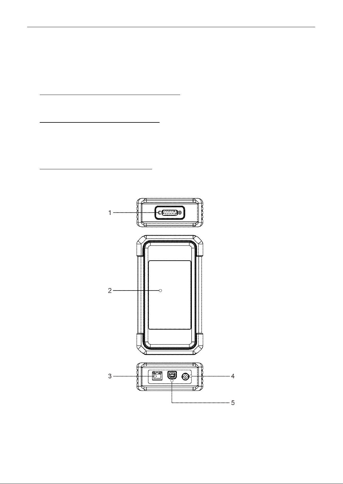
1. DB-15 diagnostic connector
Connect it to the vehicle’s DLC (Data Link Connector) port via the diagnostic cable.
2. Touch screen
3. LAN/WAN port

LAUNCH
5
Connect it to the modem via the crossover cable. It only applies to the SmartLink Super Remote
Diagnostics.
4. DC-IN power jack
It can obtain power via connecting the diagnostic cable to the vehicle’s DLC port or connecting to an
external DC power supply.
Warning: It is prohibited to connect this power jack to an external DC power supply when the SmartLink C V2.0
device is properly connected to the vehicle’s DLC port.
No responsibility can be assumed for any damage or loss caused as a result of not strictly following the warning.
5. Data I/O port
• Connect it to the tablet to perform vehicle diagnosis.
• Connect it to the PC to perform J2534 reprogramming when as a J2534 PassThru device.
1.4 Technical Parameters
1. Display tablet
Operating system: Android
Memory: 4GB
Storage: 64GB
Screen: 10.1 inch capacitive touch screen with a resolution of 1280 x 800 pixels
Camera: Rear-facing 8.0MP camera
Connectivity:
• Wi-Fi (802.11a/b/g/n/ac)
• Bluetooth
Working temperature: 0℃ ~ 50℃
Storage temperature: -20 ~ ℃ 70℃
2. SmartLink C V2.0 device
Size: 200mm x 110mm x 47mm
Working voltage: DC 9~36V
Power consumption: ≤ 6W
Communication: wireless and wired
Working temperature: 0℃~ 50℃

LAUNCH
6
2 Initial Use
2.1 Charging & Turning On
1. Plug one end of the included charging port of the tablet, and the other end to the power adaptor.
2. Connect the other end to the AC outlet.
If appears on the screen, it indicates it is being charged. If the logo changes into , it indicates that
the battery is fully charged. Unplug the power adaptor from the tablet.
Note: If the battery remains unused for a long period of time or the battery is completely discharged, it is normal
that the tool will not power on while being charged. Please charge it for a period of 5 minutes and then turn it on.
Warning: Please use the included power adaptor to charge your tool. No responsibility can be assumed for any
damage or loss caused as a result of using power adaptors other than the one supplied.
Press [POWER] for 3 seconds, an option menu will pop up on the screen. Tap Power off to turn the
tool off.
2.2 Screen Layout
The following on-screen buttons are available on the bottom of the screen.
BACK: Tap it to return to the previous screen.
HOME: Tap it to navigate to the Android’s home screen.
Recent Apps: Tap it to view the recently launched applications.
Screenshot: Tap it to capture the current screen.
2.3 Adjust Brightness
Note: Reducing the brightness of the screen is helpful to conserve the battery power.
1. On the home screen, tap Settings -> Display -> Brightness level.
2. Drag the slider to adjust it.
2.4 Change System Language
The tool supports multiple system languages. To change the language of the tool, please do the
following:
1. On the home screen, tap Settings -> System -> Language & input -> Languages.
2. Tap Add a language, and then choose the desired language from the list.
3. Tap and hold the desired language and drag it to the top of the screen and then release it, the
system will change into the target language.
2.5 Set Standby Time
If no activities are made within the defined standby period, the screen will be locked automatically and
the system enters sleep mode to save power.
1. On the home screen, tap Settings -> Display -> Advanced -> Sleep.
2. Choose the desired sleep time.

LAUNCH
7
2.6 WLAN Setup
The tablet has built-in Wi-Fi that can be used to get online. Once you’re online, you can register the tool,
surf the Internet, get apps, send email, launch the remote diagnosis, and check for software updates
etc.
Connect to a Wi-Fi network
1. On the home screen, tap Settings -> Network & Internet -> WLAN.
2. Slide the Wi-Fi switch to ON, the tablet starts searching for available wireless networks.
3. Select a wireless network,
If the chosen network is open, the tablet will connect automatically.
If the selected network is encrypted, a network password will need to be entered.
4. When Connected appears, it indicates the Wi-Fi connection is complete.
Note: When Wi-Fi is not required, this should be disabled to conserve battery power.
Disconnect from a Wi-Fi network
1. On the home screen, tap Settings -> Network & Internet -> WLAN.
2. Tap the network with a Connected status, then tap Disconnect.
LAUNCH
8
3 Register & Update
3.1 Register & Update
For initial use, the registration is the necessary first procedure to activate the tool.
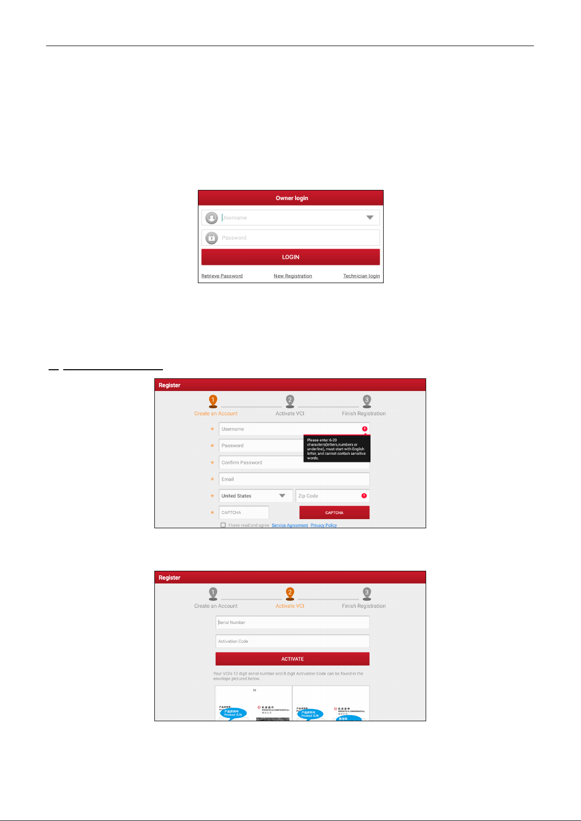
Tap the application icon on the home screen to launch it, and then tap Login on the upper right corner
of the screen to enter the following screen.
(If you are a new user, follow A to proceed.)
(If you have registered to be a member, go to B to login the system directly.)
(If you have bound a sub-account to this tool, go to C to login the system.)
(In case you forgot password, refer to D to reset a new password.)
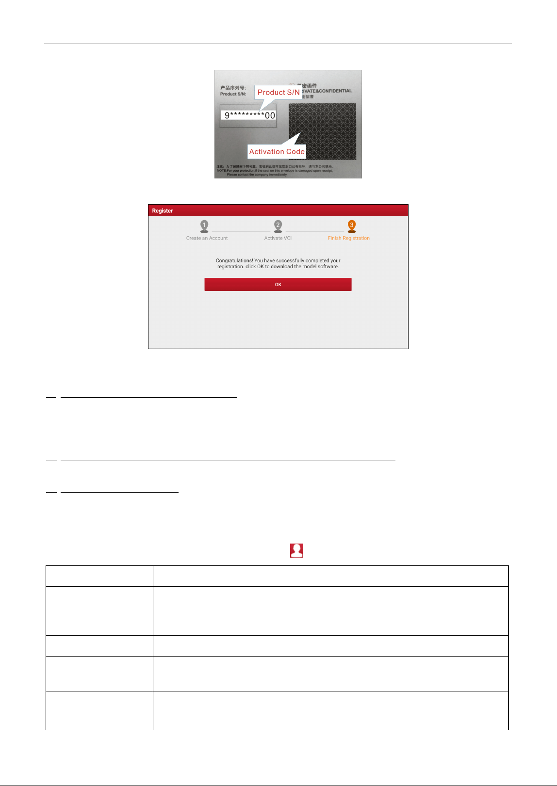
A. If you are a new user, tap New Registration to enter the sign-up page.
In the above figure, fill in the information in each field (Items with * must be filled). After inputting, tap
Register, a screen similar to the following will appear:
Input the 12-digit Product Serial Number and 8-digit Activation Code (can be obtained from the
password envelope), and then tap Activate.
LAUNCH
9
Tap OK to navigate to the update center to update all available software.
After the registration is successfully complete, the wireless communication between the tablet and the
SmartLink C device is automatically established and user has no need to configure it again.
B. If you have registered to be a member, input your name and password, and then tap Login to enter
the main menu screen directly.
Note: The tablet has an auto-save function. Once the username and password are correctly entered, the system
will automatically store it. Next time you login the system, you will not be asked to input the account manually.
C. If you have created a sub-account or bound an existing account to the tool, tap Technician login to
login. For more details on sub-accounts, refer to Chapter 11.6.
D. If you forgot the password, tap Retrieve password and then follow on-screen instructions to set a
new password.
3.2 Job Menu
After logging in, the Login button will change into the button. It mainly includes the following items:
Name
Description
Intelligent Diagnose
•
Obtain vehicle data from the cloud server to perform quick test via reading
VIN, to avoid various defects resulting from step-by-step menu selection.
• Check the historical repair records online.
Local
Diagno
s
e
To diagnose a vehicle manually.
Remote Diagnose
There are two remote diagnostics platforms available: SmartLink Super
remote diagnostics solution and X431 Remote Diagnostics.
EV
To diagnose the electronic control systems, detect battery pack and perform
some service functions of new-energy vehicles.

LAUNCH
10
Note: This function needs to work with New Energy Vehicle Diagnosis Add-on
Kit (optional), which can be purchased from the authorized dealer.
Special Function
It offers coding, reset, relearn and more service functions, to help vehicles get
back to functional status after repair or replacement.
Toolbox
Additional add-on tools include TPMS, ADAS, Oscilloscope, Sensor
simulator, BST360 Battery Tester, Immobilizer programmer, Videoscope,
Current clamp, Multimeter, Insulation Tester, Key programmer and more.
Software Update
To update vehicle diagnostic software and APK.
X-431 Diagnostic Kit
Includes vehicle coverage, CANBUS pin detection, CANScope, and Fix
connector firmware/system etc.
Feedback
To feed back the recent 20 diagnostic logs to us for issue analysis.
Mall
Subscribe some extra software or service functions that are not included in
the diagnostic tool online.
LAUNCH Academy
Include abundant repair case, operation skills and training videos for quick
reference.
Repair Info
Check repair information and ask for support via Facebook or from after-
sales
team.
User Info
Manage VCI, diagnostic reports & records, change password, order and
logout / login etc.
Settings
Make some system settings of diagnostic application.
About
Include software version, product manual, service agreement and privacy
policy etc.

LAUNCH
11
4 Connections
4.1 Preparation
1. Make sure that the ignition is turned off and vehicle battery voltage range is 9-14V or 18-30V.
2. Find DLC location.
For passenger cars, the DLC(Data Link Connector) is usually located 12 inches from the center of the
instrument panel, under or around the driver’s side for most vehicles. For some vehicles with special designs,
the DLC location may vary. Refer to the following figure for location.
A. Opel, Volkswagen, Audi
B. Honda
C. Volkswagen
D. Opel, Volkswagen, Citroen
E. Changan
F. Hyundai, Daewoo, Kia, Honda, Toyota, Nissan, Mitsubishi, Renault, Opel, BMW, Mercedes-Benz, Mazda,
Volkswagen, Audi, GM, Chrysler, Peugeot, Regal, Beijing Jeep, Citroen and other most popular models
If the DLC cannot be found, refer to the vehicle’s service manual for the location.
For commercial vehicles, the DLC is always located in driver’s cab.
3. Refer to Chapter 4.2 to make connection.
4. Turn the vehicle’ ignition ON with engine OFF.
5. Now the tool is ready for diagnostics.
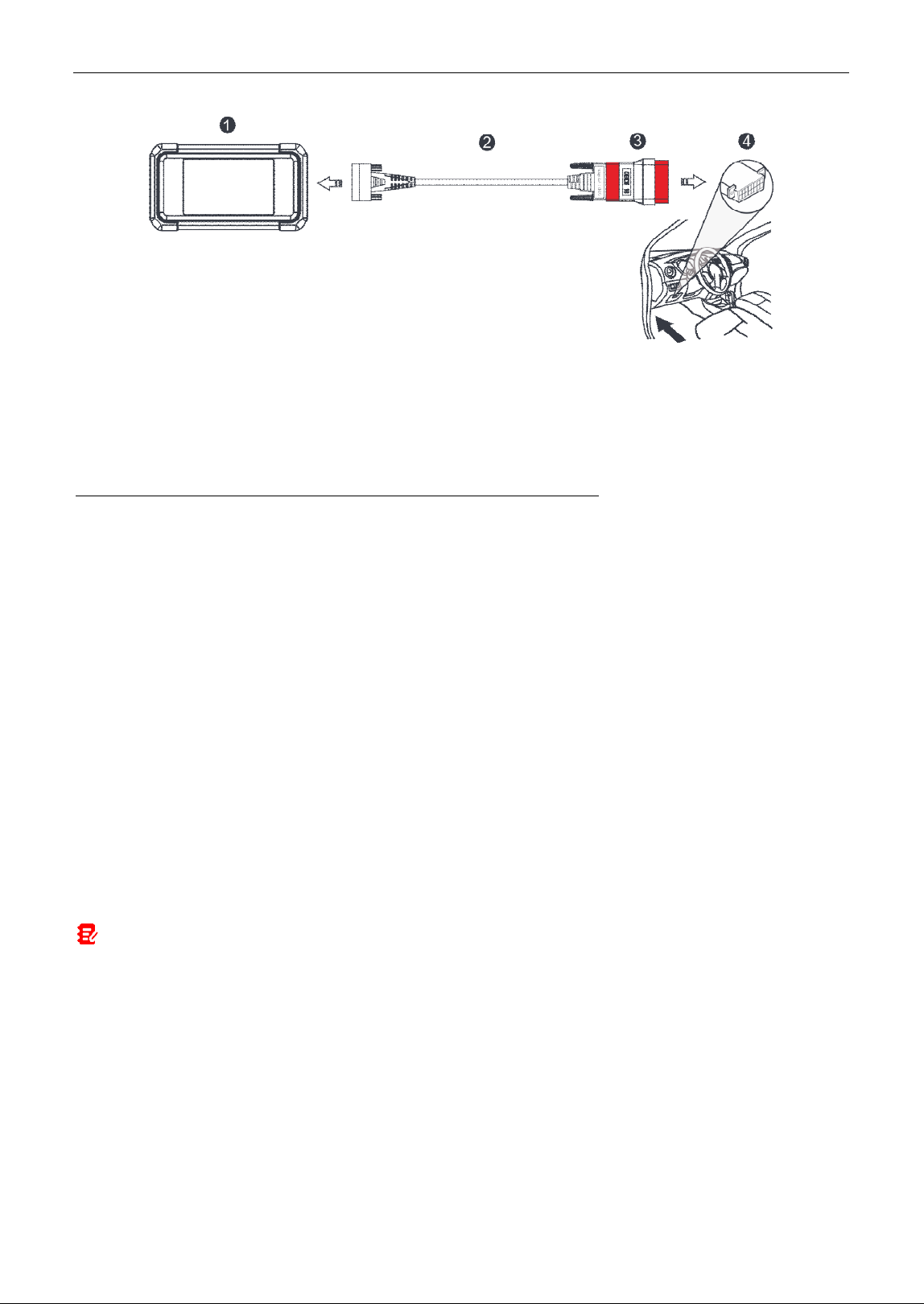
4.2 Vehicle Connection
The method used to connect the VCI device to a vehicle’s DLC depends on the vehicle’s configuration
as follows:
For OBD II vehicles, use the included diagnostic cable (DB15F to HD15F data cable and HD15M to
OBD16 adaptor) to connect the VCI to the vehicle’s DLC port.
LAUNCH
12
1. VCI
2. DB15F to HD15F data cable
3. HD15F to OBD16 adaptor
4. Vehicle’s DLC port
For non-OBDII vehicles, refer to the above figure to make connection.
1. Select the appropriate adaptor according to the vehicle’s DLC port type (4).
2. Loosen the captive screws of the DB15F to HD15F data cable (2) and disconnect the HD15F to
OBD16 adaptor (3) from the data cable.
3. Connect the data cable (2) with the target adaptor (sold separately) on the above figure and tighten
the screws. Other steps shall also apply.
If you choose to perform vehicle diagnosis via data cable, connect one end of the data cable into the
VCI, and the other end into the data I/O port of the tablet.
4.3 Communication Setup
There are two kinds of ways available for the tablet to communicate with the VCI device: wireless and
wired (USB).
After the user registration is successfully finished, the wireless communication between the tablet and
the VCI device is automatically established and user has no need to configure it again.
The USB connection is a simple & quick way to establish communication between the tablet and the
VCI. After properly connecting the data cable from the tablet to the VCI, the VCI navigation button at
the bottom of the screen will be enabled indicating the USB connection is successful.
Note: The USB connection provides the most stable and fastest communication. When all communication
methods are applied at the same time, the tablet will use the wired communication as the default priority.
LAUNCH
13
5 Diagnosis
5.1 Intelligent Diagnose
Through simple wireless communication between the display tablet and VCI, you can easily get the VIN
(Vehicle Identification Number) information of the currently identified vehicle. After the VIN is
successfully decoded, the system will retrieve it from the remote server and then guide you to vehicle
information page without the necessity of step-by-step manual menu selection.
The vehicle information page lists all historical diagnostic records of the vehicle, which lets the
technician have a total command of the vehicle faults. In addition, a quick dial to local diagnose and
diagnostic function are also available on this page for reducing the roundabout time and increasing
productivity.
*Notes:
•
Before using this function, please make sure the VCI device is properly connected to the vehicle’s DLC. For
detailed connection, see Chapter 4.2.
•
A stable network connection is required for this function.
Follow the steps below to proceed.
1. Tap Intelligent Diagnose on the Job menu screen to start pairing with the VCI device.
2. After pairing is complete, the tablet starts reading the vehicle VIN.
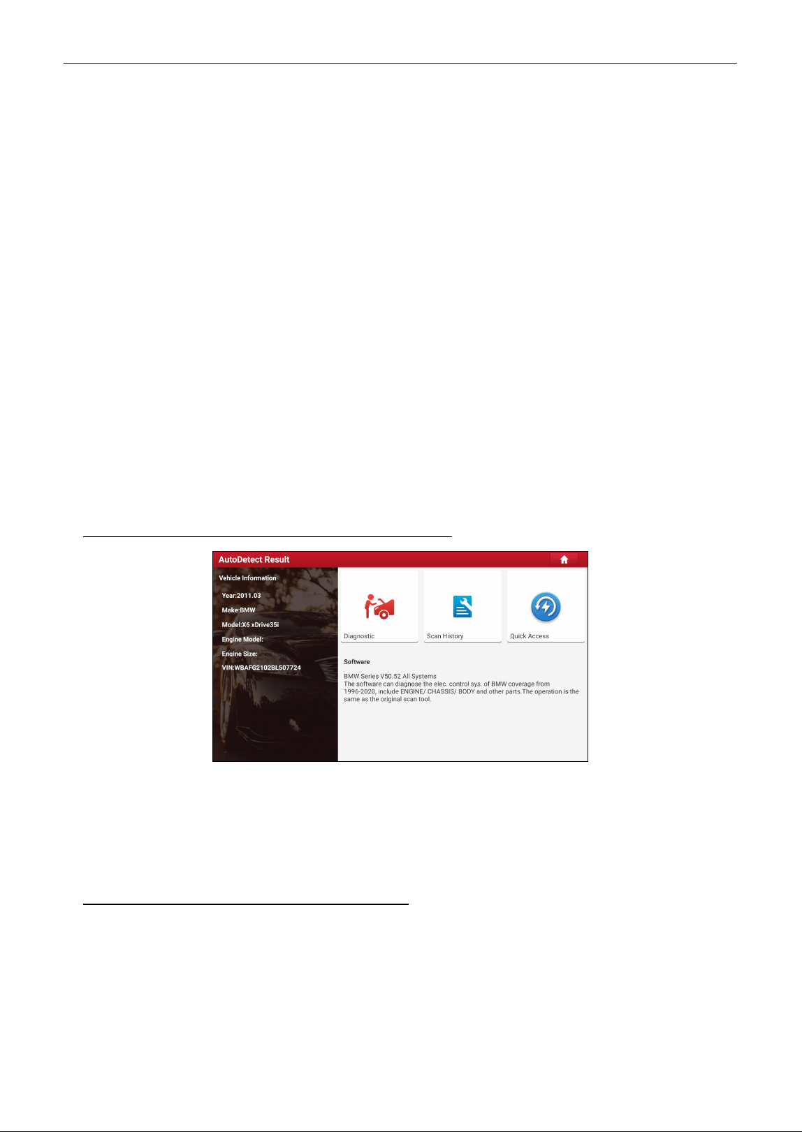
A. If the VIN can be found from the remote server database, the following screen will appear:
• Tap Diagnostic to start a new diagnostic session.
• Tap Scan History to view its historical repair record. If there are records available, it will be listed on
the screen in sequence of date. If no records exist, the screen will show “No Record.”
• To perform other functions, tap Quick access to directly go to the diagnostic function selection
screen. Choose the desired one to start a new diagnostic session.
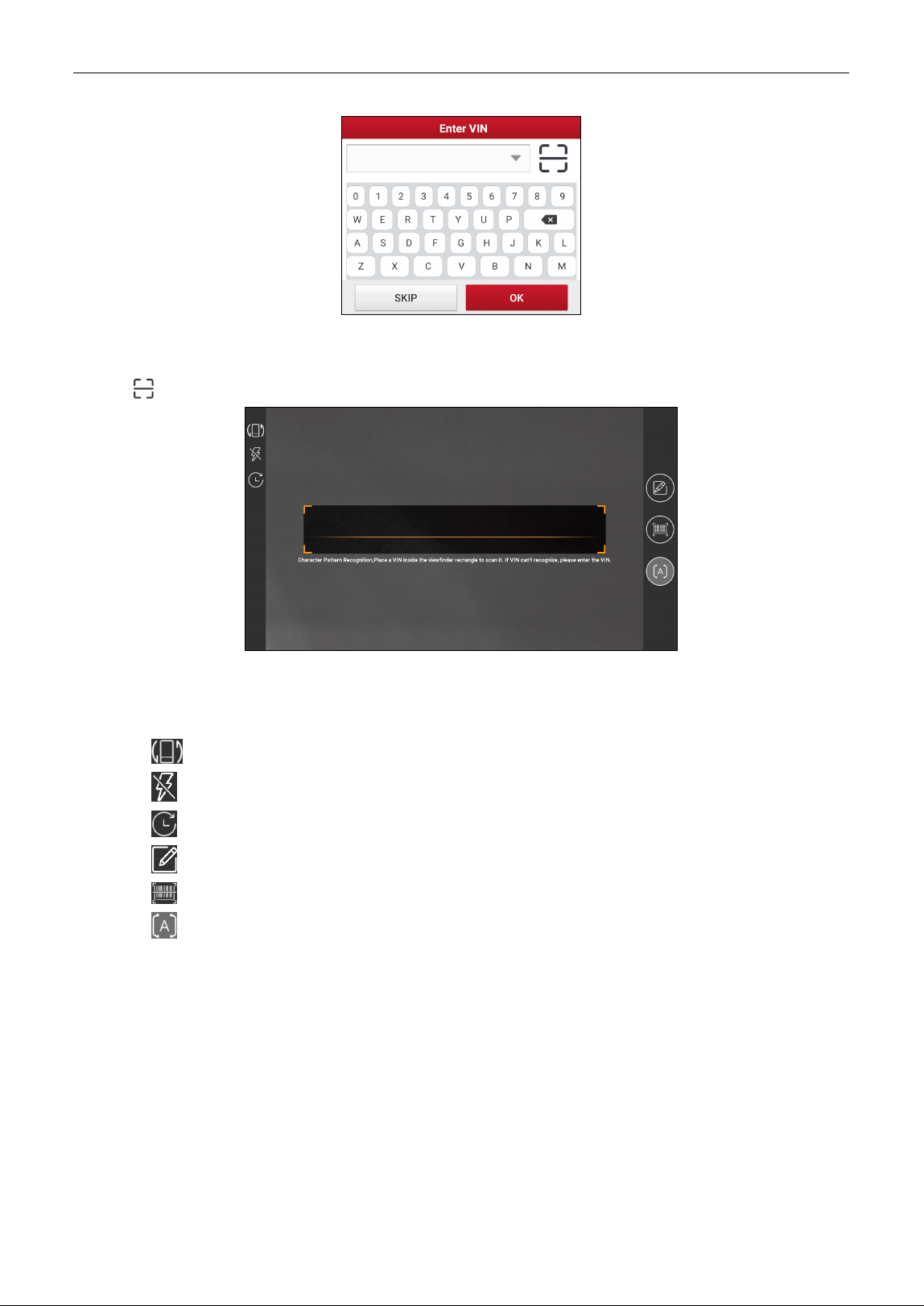
B. If the handset failed to access the VIN information, the following screen will appear:
LAUNCH
14
• Tap the input field to directly, tap OK. If the VIN exists on the remote server, the system will enter the
diagnostic function selection screen.
• Tap to launch the VIN recognition module.
Place the VIN inside the viewfinder rectangle to scan it. The most recognizable location for this
number is in the top left corner on the vehicle’s dashboard. Other locations include the driver’s door
or post, and the firewall under the hood.
• Tap to switch the display mode of the screen.
• Tap to turn the camera flash on.
• Tap to choose it from the record list if the VIN of the vehicle has been scanned before.
• Tap to input the VIN manually if the tablet has failed to decode the VIN of the vehicle.
• Tap to scan the VIN barcode.
• Tap to scan the VIN character.
*Note: In general, vehicle identification numbers are standardized - all contain 17 characters. VIN characters
may be capital letters A through Z and numbers 1 through 0; however, the letters I, O and Q are never used in
order to avoid mistakes of misreading. No signs or spaces are allowed in the VIN.
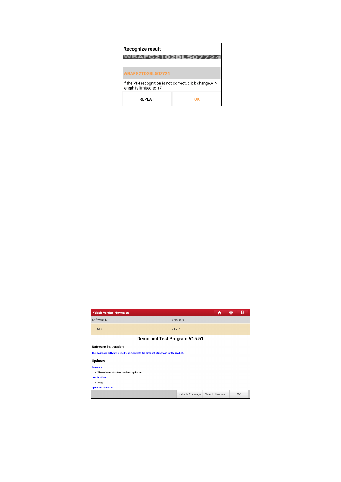
After scanning, the screen automatically displays the result.
LAUNCH
15
If the VIN scanned is incorrect, tap the result field to modify it and then tap OK. To scan it again, tap
REPEAT. If the VIN exists on the remote server, the system will enter the diagnostic function selection
screen.
5.2 Local Diagnose
This function allows you to diagnose electronic control systems of single vehicle models by manually
executing the menu-driven command.
Tap Local Diagnose to enter the vehicle selection page.
2 approaches are provided for you to access the vehicle diagnostic software. Choose any one of the
following ways:
1. VINSCAN enables you to access it more quickly. In this case, Camera Scan and Enter VIN are
available.
Camera Scan: Scan the VIN automatically.
Enter VIN: Input the vehicle VIN manually.
If the tablet successfully identifies the vehicle model, it will directly enter the diagnostic function
selection menu.
2. Tap a corresponding diagnostic software logo, and then follow the on-screen instruction to access
the diagnostic software.
Take Demo (Version 15.51) as an example to demonstrate how to diagnose a vehicle.
1). Select diagnostic software version: Tap the DEMO to go to Step 2.
On-screen Buttons:
Vehicle Coverage: Tap to view the vehicle models that the current diagnostic software covers.
Search Bluetooth: Tap to search for the available VCI.
Note: No Bluetooth connection is required for DEMO program.
LAUNCH
16
OK: Tap it to go to next step.
2). Select vehicle model. Here we take TOYOTA for example to demonstrate how to diagnose a
vehicle.
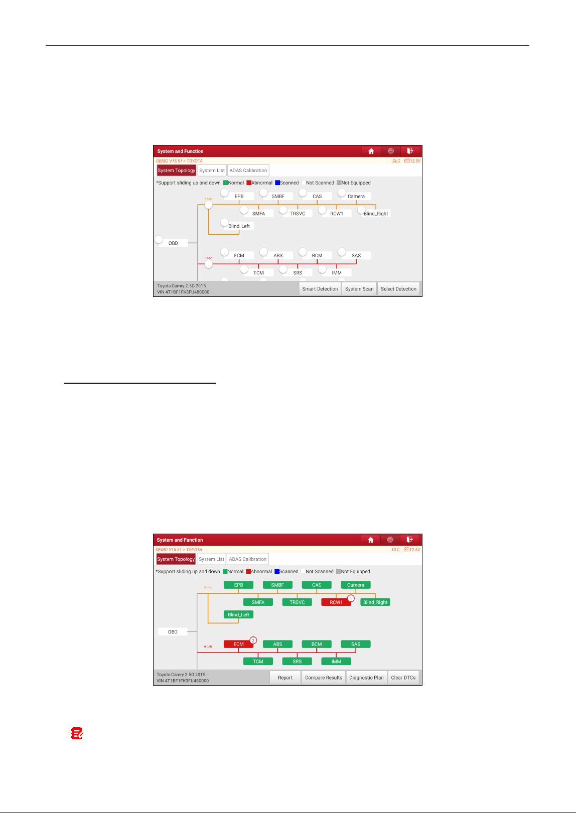
3). Select the desired test item to proceed.
System Topology: Displays all available vehicle systems in form of topology structure.
System List: Displays all available vehicle systems in form of list.
ADAS Calibration: Performs ADAS calibration operations. It is extracted from the system list as a
functional module and provides a quick access to ADAS system.
While in System Topology mode, different highlight bars indicate different detection status.
On-screen Buttons:
Smart Detection: Tap to quickly access all the electronic control units of the vehicle and generate a
detailed report about vehicle health. The tested systems malfunctioning are displayed in red with a
number indicator displaying DTC quantity and the systems with functioning properly are displayed in
green.
Note: Diagnostic Trouble Codes or Fault Codes can be used to identify which engine systems or components that
are malfunctioning. Never replace a part based only on the DTC definition. Retrieving and using DTCs for
troubleshooting vehicle operation is only one part of an overall diagnostic strategy. Follow testing procedures (in
vehicle’s service manual), instructions and flowcharts to confirm the locations of the problem.
• Report: Tap to save the current data in text format. All reports are saved in User Info -> My
Report -> Health Reports.
Notes:
1. Diagnostic report is classified into two categories: Pre-Repair report and Post-Repair report. To facilitate
LAUNCH
17
the comparison of the pre-repair and post-repair reports and get accurate test result, please make sure you
saved the right type of the diagnostic report.
2. By default, the workshop information is blank. You can configure and revise it from User Info ->
Settings -> Shop Information. After you configured the information, it will be automatically generated
every time the diagnostic report is saved. All vehicle and workshop information will be appended as a
tag on the diagnostic report, which allows you to easily retrieve the desired report while performing
Filter function of Diagnostic Report.
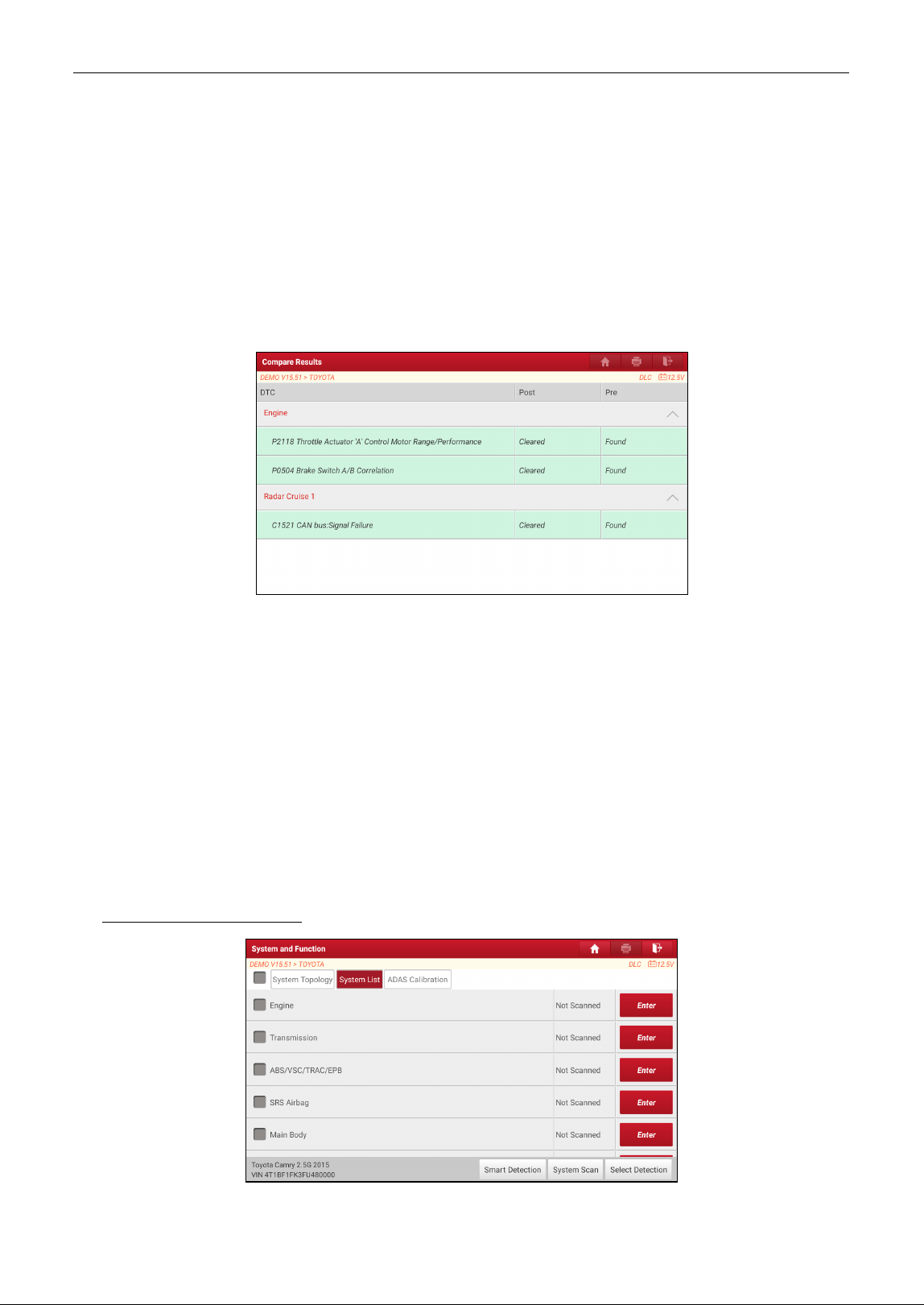
• Compare Results: Tap to select the pre-repair report to compare. By comparison of the pre- and
post- repair reports, you can easily identify which DTCs are cleared and which remain unfixed.
Note: Before performing this function, please make sure that: 1) You have saved a pre-repair report of the
currently tested vehicle; and 2) You have already made some repairs and service and cleared the DTCs after
the pre-repair reported is generated. Otherwise, no differences exist between the pre- and post- repair
reports.
• Diagnostic Plan: Figures out the diagnostic plan and repair solutions for the detected DTCs.
• Clear DTCs: Tap to clear the existing diagnostic trouble codes.
Note: Clearing DTCs does not fix the problem(s) that caused the code(s) to be set. If proper repairs to
correct the problem that caused the code(s) to be set are not made, the code(s) will appear again and the
check engine light will illuminate as soon as the problem that cause the DTC to set manifests itself.
System Scan: Tap to quickly scan which systems are installed on the vehicle.
Select Detection: Select certain system manually to start scanning.
While in System List mode, the following screen will appear.
• Enter: Select certain system, and tap this button to enter the diagnostic function selection screen.
LAUNCH
18
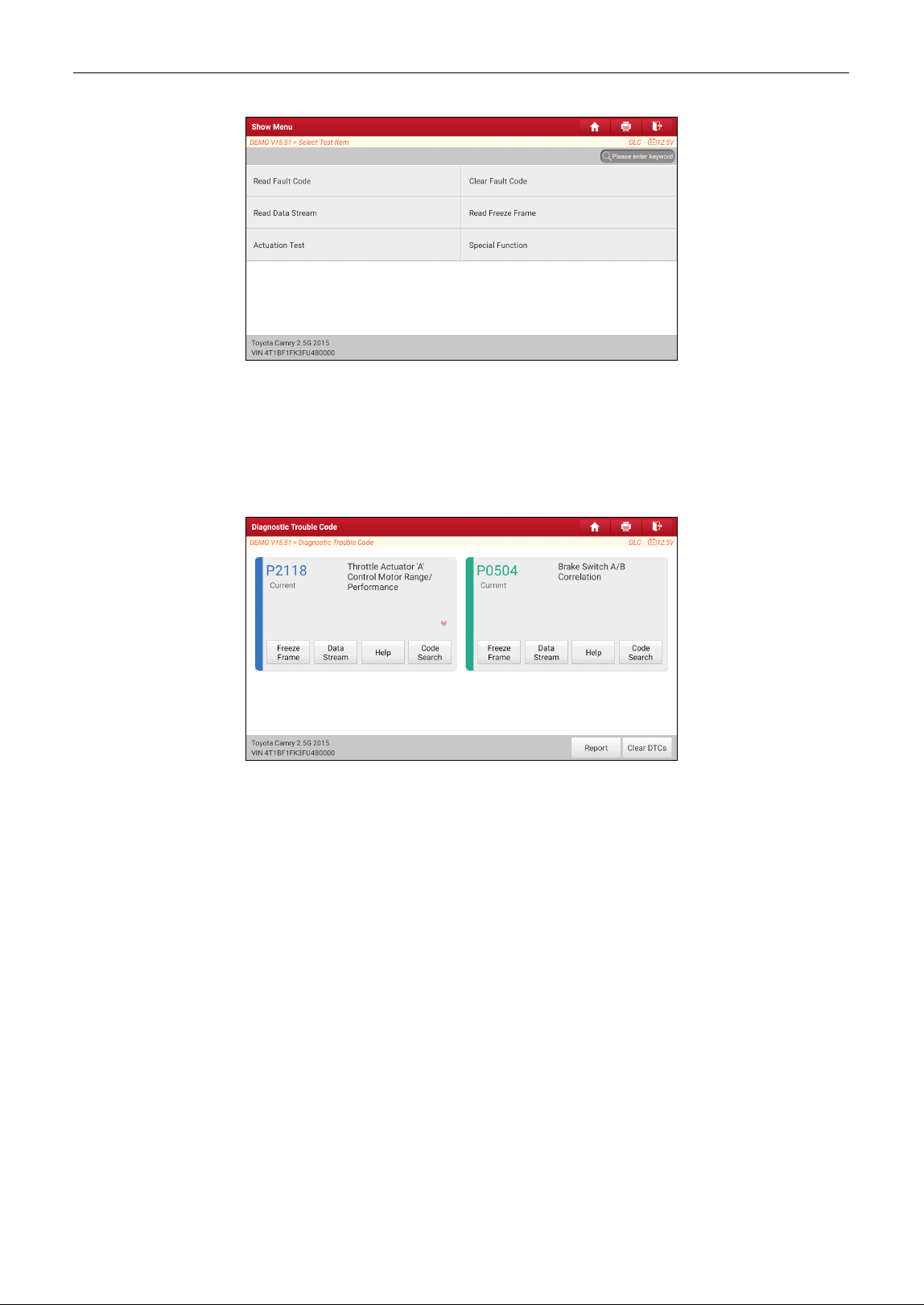
In general, the diagnostic functions vary with different vehicle models. It mainly includes the following
options:
A. Read Fault Code
This function displays the detailed information of DTC records retrieved from the vehicle’s control
system.
On-screen Buttons:
Freeze Frame: Tap it to view the snapshot of critical parameter values at the time the DTC is set.
Help: Tap to view the help information.
Code Search: Tap it to search for more information about the current DTC online.
Report: To save the current data in text format. All reports are saved in User Info -> My Report ->
Health Reports.
Clear DTCs: Tap to clear the existing diagnostic trouble codes.
B. Clear Fault Code
This option can erase the codes from the vehicle. Before the operation, please make sure the vehicle’s
ignition key is in the ON position with the engine off.
Note: After clearing, you should retrieve trouble codes once more or turn ignition on and retrieve codes again. If
there are still some trouble codes in the system, please troubleshoot the code using a factory diagnosis guide,
then clear the code and recheck.
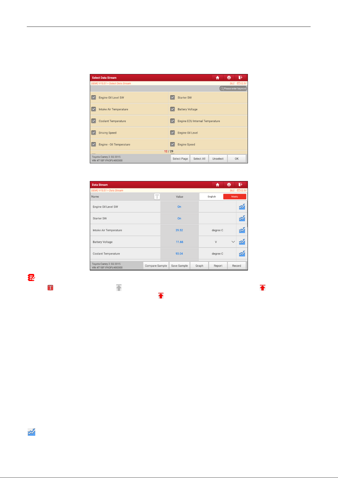
C. Read Data Stream
This option retrieves and displays live data and parameters from the vehicle’s ECU.
Caution: If you must drive the vehicle in order to perform a troubleshooting procedure, ALWAYS have a second
LAUNCH
19
person help you. Trying to drive and operate the diagnostic tool at the same time is dangerous, and could cause a
serious traffic accident.
Tap Read Data Stream, the following screen will appear:
After selecting the desired items, tap OK to enter the data stream reading page.
Notes:
1.
Tap to set the display style. indicates sticky top. If it is tapped, it will change into . On the data
stream display screen, the data stream item with will be shown on the top of the selected data stream list.
To remove it from the top of the list, just tap it again.
B indicates this item will be displayed in
Bold
.
A indicates this item will be displayed in Red.
2.
Tap
English
or
Metric
to switch the measurement unit.
3.
If the value of the data stream item is out of the range of the standard (reference) value, the whole line will
display in red. If it complies with the reference value, it displays in blue (normal mode).
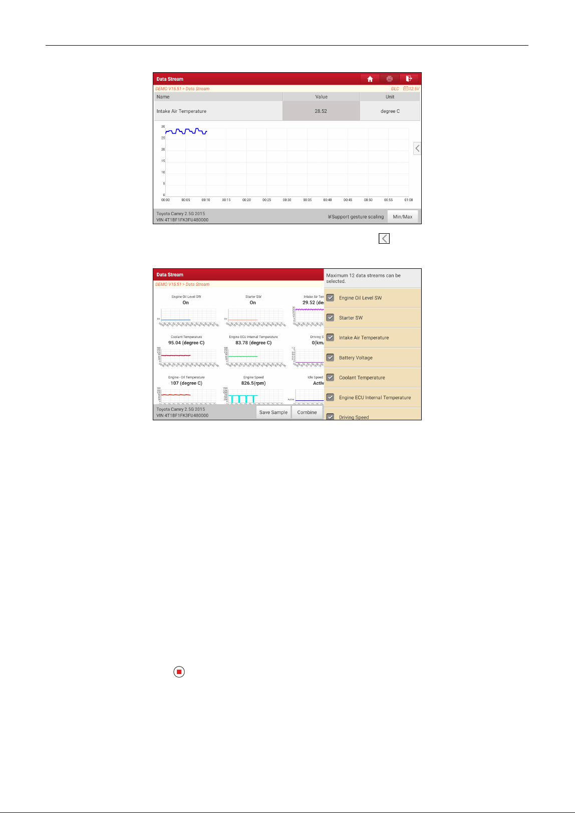
There are 3 types of display modes available for data viewing, allowing you to view various types of
parameters in the most suitable way.
Value – this is the default mode which displays the parameters in texts and shows in list format.
Graph – displays the parameters in waveform graphs.
Combine – this option is mostly used in graph merge status for data comparison.
In this case,
different items are marked in different colors.
On-screen Buttons:
: Tap it to view the live waveform.
LAUNCH
20
Graph: Tap it to view the waveform of the selected data streams. Tap on the edge of the screen to
customize the target data streams for displaying.
Compare Sample: Tap it to select the sample data stream file, the values you customized and saved in
process of data stream sampling will be imported into the Standard Range column for your
comparison.
Note: Before executing this function, you have to sample the values of data stream items and save it as a sample
data stream file.
Report: To save the current data in text format. All reports are saved in User Info -> My Report ->
Health Reports.
Record: Tap to start recording diagnostic data. Recorded live data can serve as valuable information to
help you in troubleshooting of vehicle problems. All recorded files are stored in User Info -> My Report
-> Recorded Data.
Help: Tap to view the help information.
Save Sample: This item enables you to customize the standard range of live data stream items and
save it as sample file. Each time you run the data stream items, you can call out the corresponding
sample data to overwrite the current standard range.
Tap it to start recording the sample data
(Note: Only data stream items with units will be recorded)
. Once
recording is complete, tap to stop it and navigate to the data modification screen.

LAUNCH
21
Tap the value to change it. After modifying all desired items, tap Save to save it. All data stream files
are stored in User Info -> Sample.
D. Read Freeze Frame
This option takes the snapshot of the operating conditions when a vehicle fault occurs.
E. Actuation Test
This option is used to access vehicle-specific subsystem and component tests. Available test vary by
vehicle manufacturer, year, and model.
During the actuation test, the tablet outputs commands to the ECU in order to drive the actuators, and
then determines the integrity of the system or parts by reading the ECU data, or by monitoring the
operation of the actuators, such as switching a injector between two operating states.
F. Special Functions
This option offers coding, reset, relearn and more service functions, to help vehicles get back to
functional status after repair or replacement. Available tests vary by vehicle manufacturer, year, and
model.
5.3 Remote Diagnose
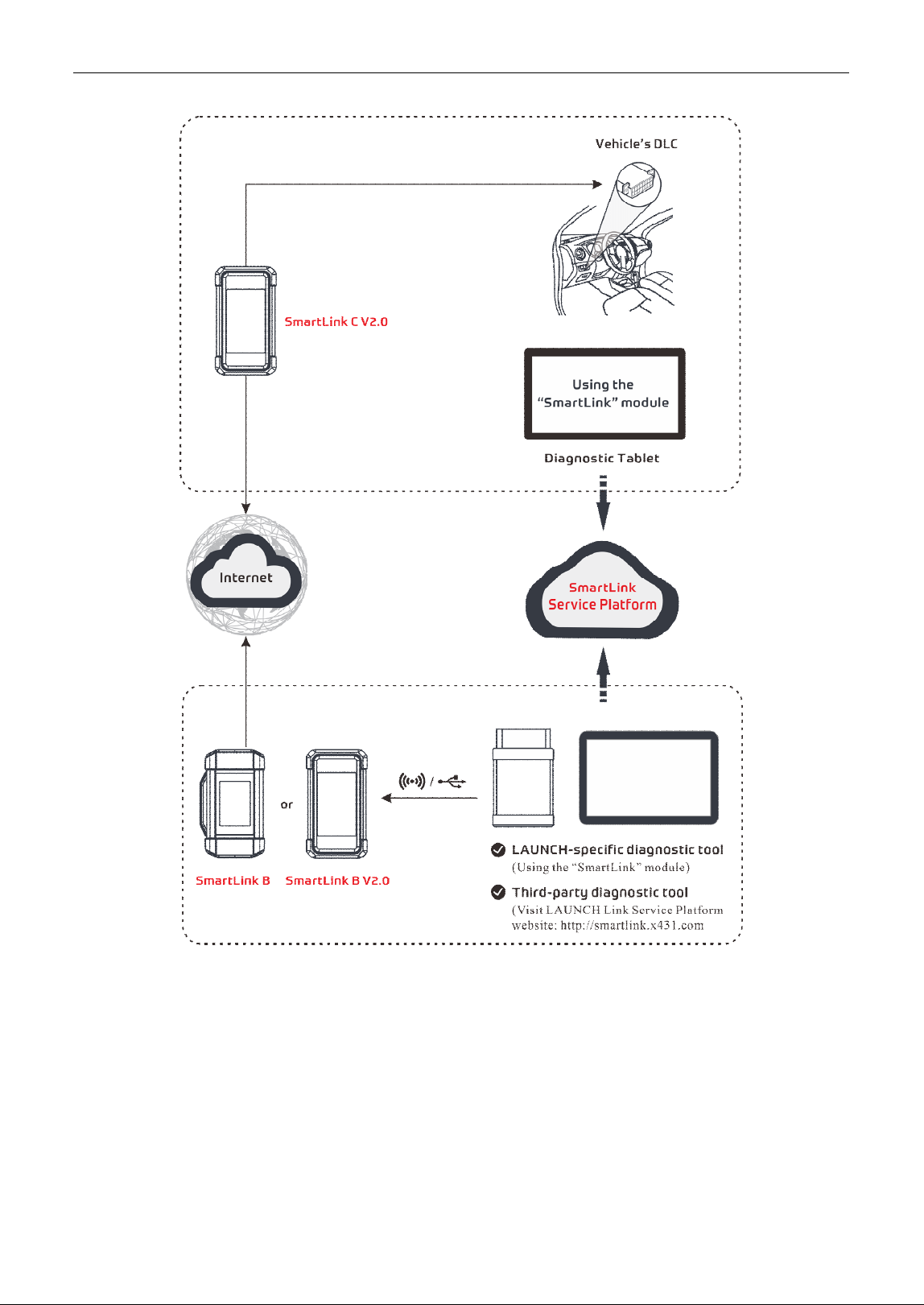
5.3.1 SmartLink Super Remote Diagnostics
SmartLink is a newly developed powerful service system dedicated to remote vehicle diagnosis and
service. In the SmartLink ecology system, if a technician (SmartLink C) does not have time to puzzle
through a tough vehicle problem, he can seek a trusted second opinion or additional expertise on
various vehicle issues from remote master technicians or repair shops (SmartLink B). SmartLink B
enables the shop owner to greatly increase customer’s retention and boost shop revenue by providing
professional technical assistance service.
It mainly consists of the following parts:
LAUNCH
22
• SmartLink Service Platform – It can be accessed from the SmartLink module of the diagnostic
tablet. There are two modules available on the link service platform: Common user (for SmartLink C)
and Service provider (for SmartLink B).
• SmartLink C (Customer) - SmartLink Service Subscriber. In the SmartLink system, the
SmartLink C needs to perform the following operations.
1). Launch Service Link Platform: Binds SmartLink C dongles and submits remote repair orders.
2). SmartLink C Dongle: Connects to the vehicle’s DLC port for collecting the vehicle data and sends
it to the remote SmartLink B.
It supports remote diagnostic services for vehicles that meet CAN / CAN FD / J2534 vehicle
LAUNCH
23
diagnostic standards.
• SmartLink B (Business) - SmartLink Service Provider. In the SmartLink system, the SmartLink B
needs to perform the following operations.
1). Launch Service Link Platform: Binds SmartLink B dongles and accepts orders from SmartLink C.
• If the SmartLink B dongle works with the LAUNCH-specific diagnostic tool equipped with
SmartLink module, tap SmartLink to add the SmartLink B device and accepts orders on the
diagnostic tool.
• If the SmartLink B dongle works with the third-party diagnostic tool, open the browser and visit
SmartLink Service Platform website http://smartlink.x431.com (web client) to add the SmartLink B
device and accepts orders in the browser.
2). SmartLink B Dongle: After accepting the orders, it can work with the compatible diagnostic tool to
perform diagnosis of the vehicle connected to the SmartLink C dongle.
For more detailed operations, refer to the User Manual integrated in the SmartLink Platform.
5.3.2 X431 Remote Diagnostics
This option aims to help repair shops or technicians launch instant messaging and remote diagnosis,
making the repair job getting fixed faster.
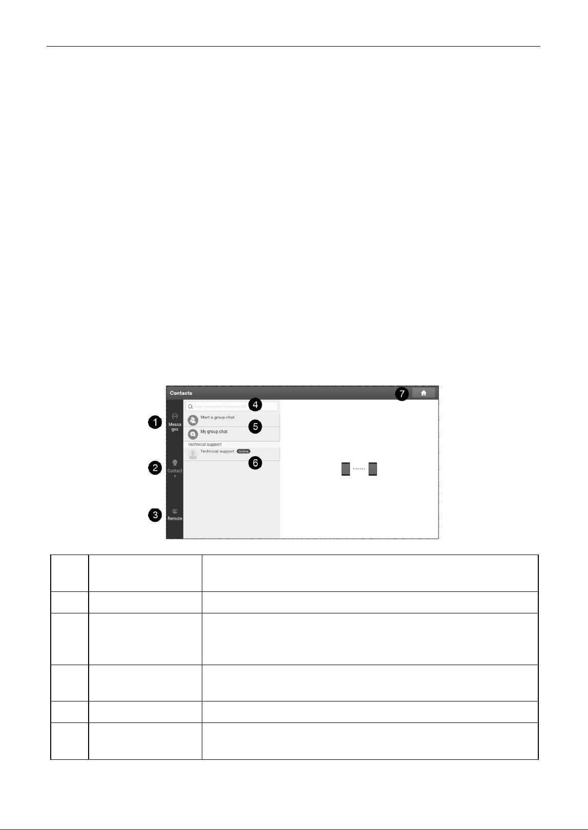
Tap Remote Diagnose -> X431 Remote Diagnosis to enter the following screen.
1 Messages tab
Once an incoming message reaches, a red dot will appear on the
upper right corner of the tab.
2 Contacts tab Tap to enter the friend list.
3 Remote
Tap to slide the switch to ON, the tool keeps online and becomes
accessible on the web client. In this ca
se, inform the technician of
your product S/N, and he/she will control your device remotely.
4 Search bar
Directly input the registered username of the tool to start searching,
and then tap the desired one to add it into your friend list.
5 Group chat operation
Used to start a group chat and manage group chat.
6 Contacts list
Displays a list of friends. The technical support is displayed by default
if no friends list is created.
LAUNCH
24
7 Home button Tap it to navigate to the home screen.
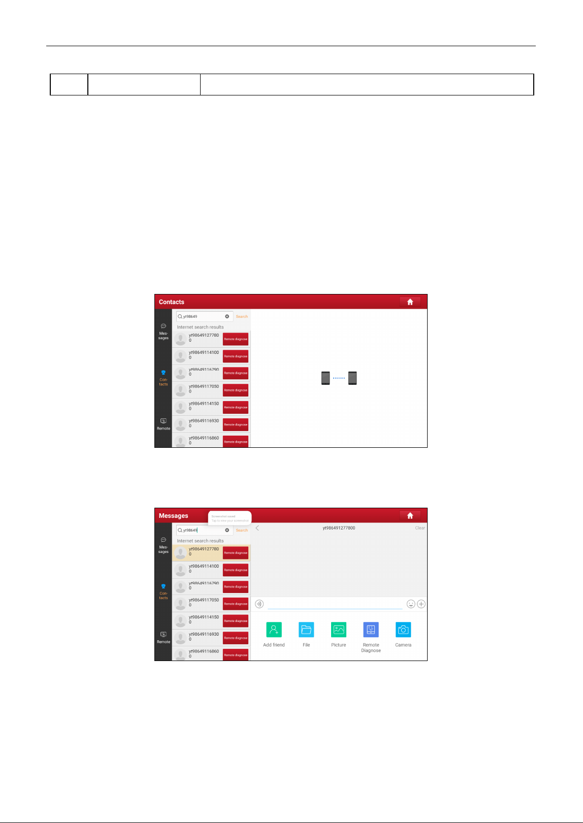
1. Adding Friends
Tap Contacts. By default it appears blank.
In the search bar, input the partner’s username and tap Search button next to the search bar to starts
searching.
The partner must be the users who have registered specific diagnostic tools. They may be the following
roles:
Workshop
Technician
golo users
Once the result matches the keyword, the following screen will appear:
Tap Remote Diagnose to launch remote diagnostics directly or follow the steps below to add the
partner into the Contacts list.
Tap the desired name from the list, the following screen will appear:
Tap Add friend to send your request.
Once the partner receives the request, a beep will sound. Tap Messages:
• Once the partner agreed your request, he/she will automatically be listed in the Contacts tab.
• If a technician sent you a friend request, tap Agree and his/her name will appear in the friend
(Contacts) list. Or tap Ignore to ignore this request.
LAUNCH
25
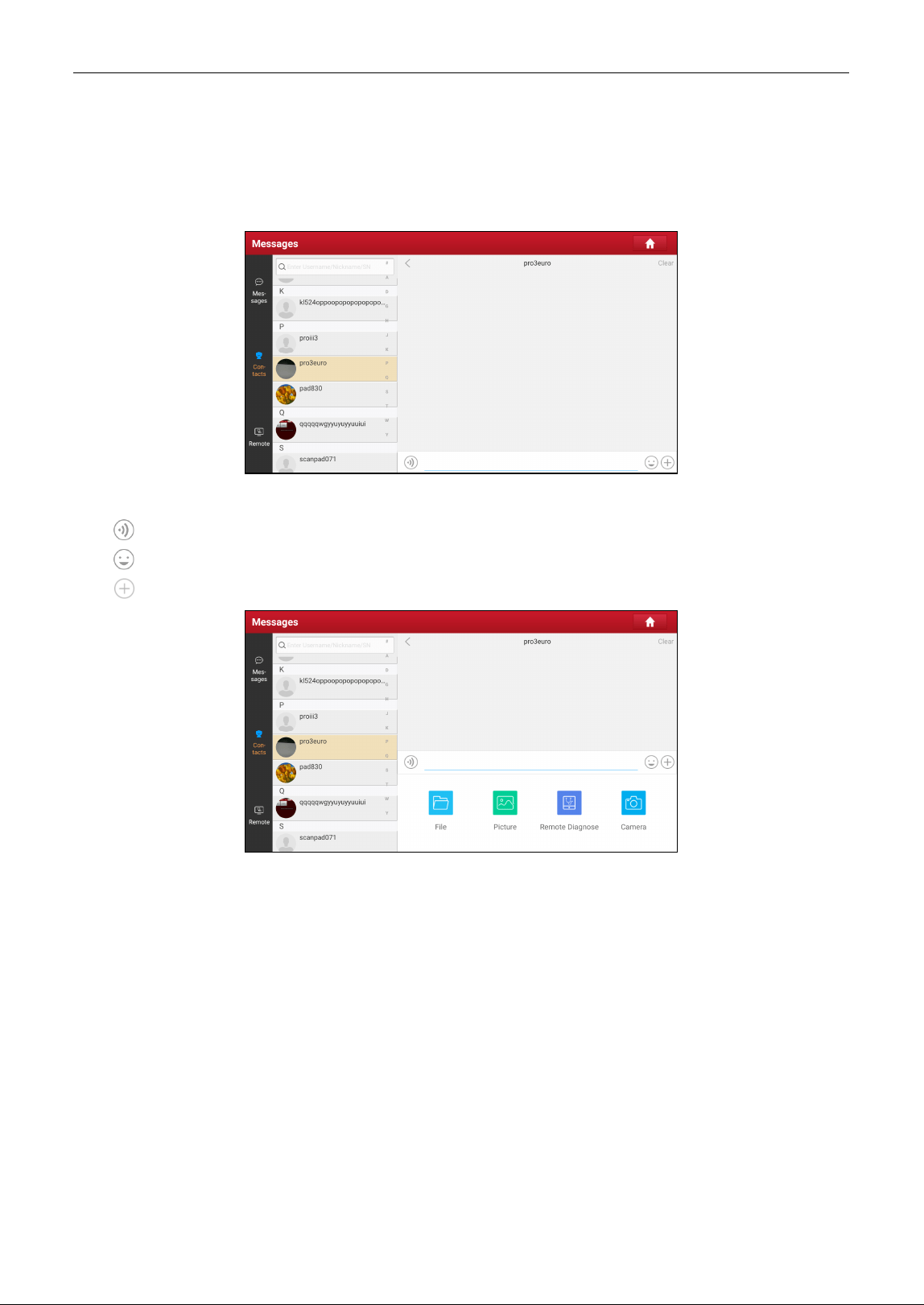
2. Start Instant Messaging
The I/M (Instant Messaging) function is open to all users who had the diagnostic tool equipped with this
module.
After adding your friends, tap the desired one’s photo to enter the following screen:
Tap the input field and use the on-screen keyboard to send the text message.
Tap
to send the voice message.
Tap
to send the emoj.
Tap
to call out more function options.
File: Choose diagnostic reports or local files to send.
Picture: Choose screenshots or pictures to send.
Remote Diagnose: To start a remote diagnostic session.
Camera: Open camera to take pictures.
Tap Clear to delete all the partner’s dialog logs.
3. Launch Remote Diagnosis (Scanner-To-Scanner)
The tool is allowed to initiate remote diagnosis with other diagnostic tools, which are equipped with this
module.
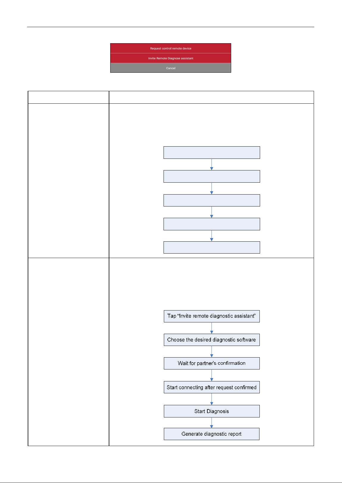
On the function option selection screen, tap Remote Diagnostic, the following pull-down menu will
appear:
LAUNCH
26
These options are defined as follows:
Actions
Results
Request control remote
device
Request to control the partner’
s device remotely to help him diagnose
the vehicle.
Note: Once vehicle diagnosis is complete, a report will be created. Input your
comments on this report, and then tap
Send Report
to send it to the partner.
Tap “Request control remote device”
Wait for partner’s confirmation
Start connecting after request confirmed
Start Diagnosis
Generate diagnostic report
Invite remote diagnostic
assistant
Use this option to invite a technician to perform a remote control on your
tool.
Note: Once you received the report from the partner, tap
View Report
to view
details. All diagnostic reports are saved under
User Info
->
My Report ->
Remote Report
.
LAUNCH
27
Cancel To cancel this operation.
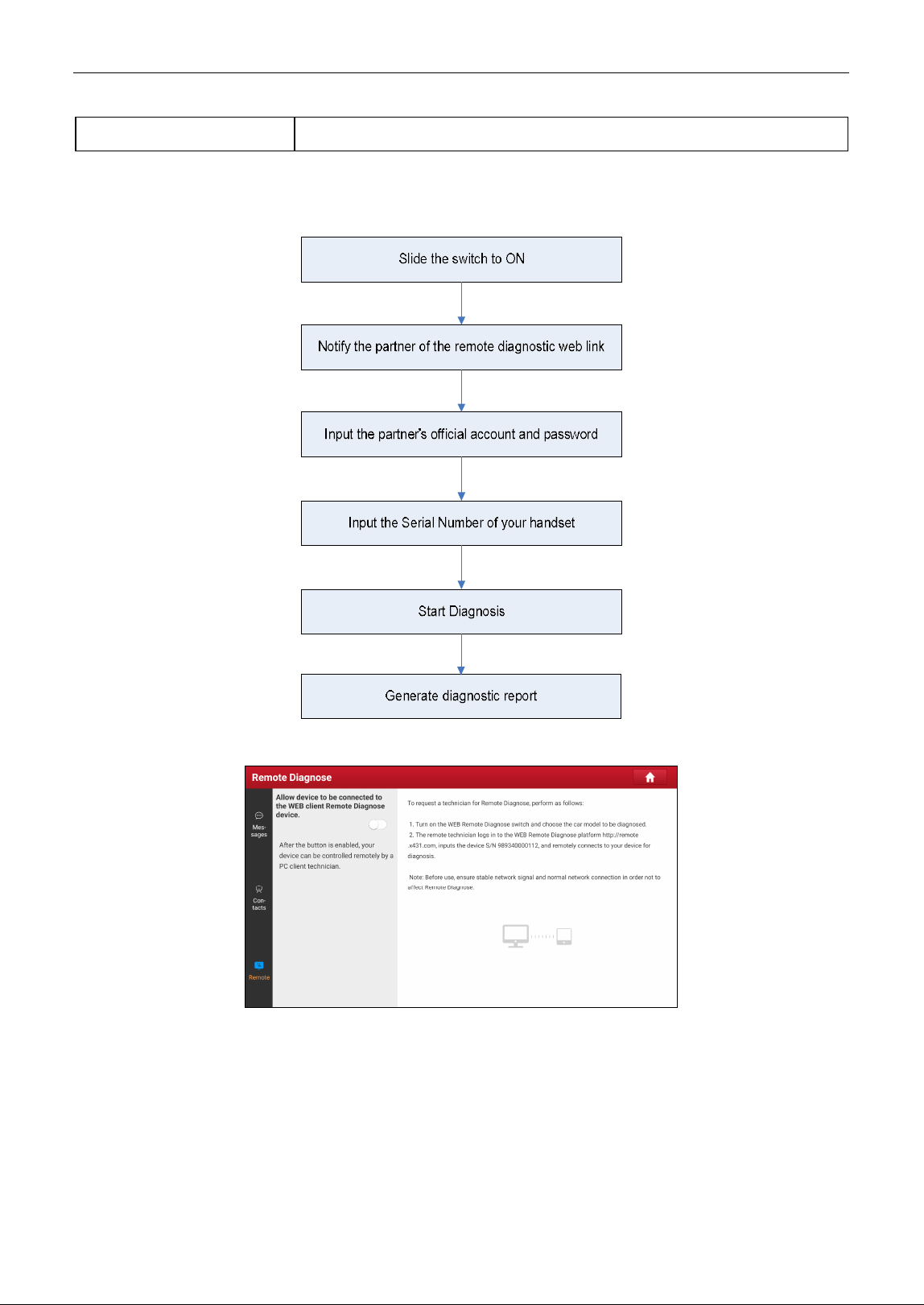
4. Launch Remote Diagnosis (Scanner-To-PC)
User also can ask for remote control from a PC client technician.
Tap Remote, the following screen will appear:
1. Slide the switch to ON so that the partner can find and connect to this device while using the PC.
2. Choose the car model to be diagnosed.
3. Notify the partner of the PC client website http://remote.x431.com. When the partner accesses the
link, the PC displays as below:
Note: Before processing remote diagnosis, please make sure the tool is properly connected to the vehicle.
LAUNCH
28
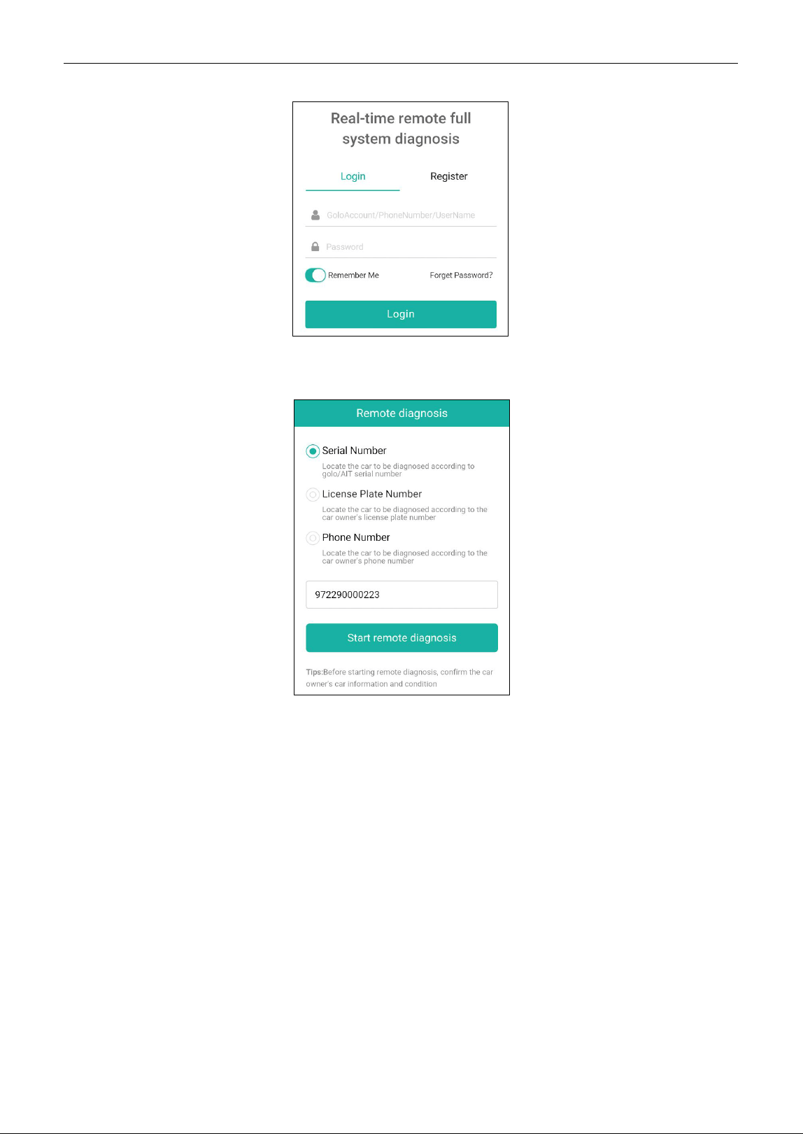
4. Tell the partner to input his own official technician account and password, and then tap Login to
navigate to the following figure.
5. Tell the partner to check the box Serial number and enter the Serial Number provided by you, and
then tap Start remote diagnosis to control your device remotely.
In process of remote diagnosis, please note the following things:
1) You are not suggested to execute any actions.
2) The partner is not allowed to save any diagnostic reports or records on your tool.
The operations in remote diagnosis are same as those in local diagnose. Once the session is complete,
a remote diagnostic report will be automatically generated.
5.4 EV (Electric Vehicle) Diagnose
This function only applies to the new energy vehicles. There are two function modules available:
Vehicle diagnosis and battery pack detection.
Note: This function needs to work with New Energy Vehicle Diagnosis Add-on Kit (optional), which can be
purchased from the authorized dealer.
5.4.1 Vehicle Diagnosis
This function is specially designed to manually diagnose electronic control systems of single new
LAUNCH
29
energy vehicle. Operations of this function are same as those in local diagnose. Refer to Chapter 5.2
for details.
5.4.2 Battery Pack Detection
This function can detect the battery pack of new energy vehicles. Two methods are provided for
selecting the battery pack: via vehicle model and via battery brand.
Take BYD E5 as an example to demonstrate how to detect battery pack.
1. Tap Battey Pack Detection.
2. Tap BYD -> E5.
3. Choose the desired BMS model to enter the following screen.
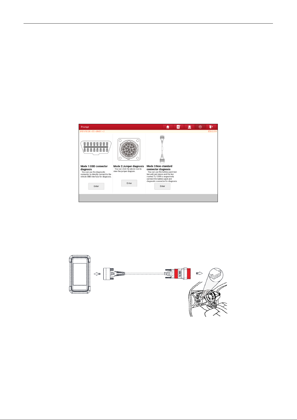
4. Select the preferred detection mode to start the detection until the system outputs the test result.
Note: The available detection mode varies with the vehicle model/battery brand. Generally the following modes
are provided:
Mode 1:
Via OBD diagnostic interface
Refer to Chapter 4.2 to make connection.
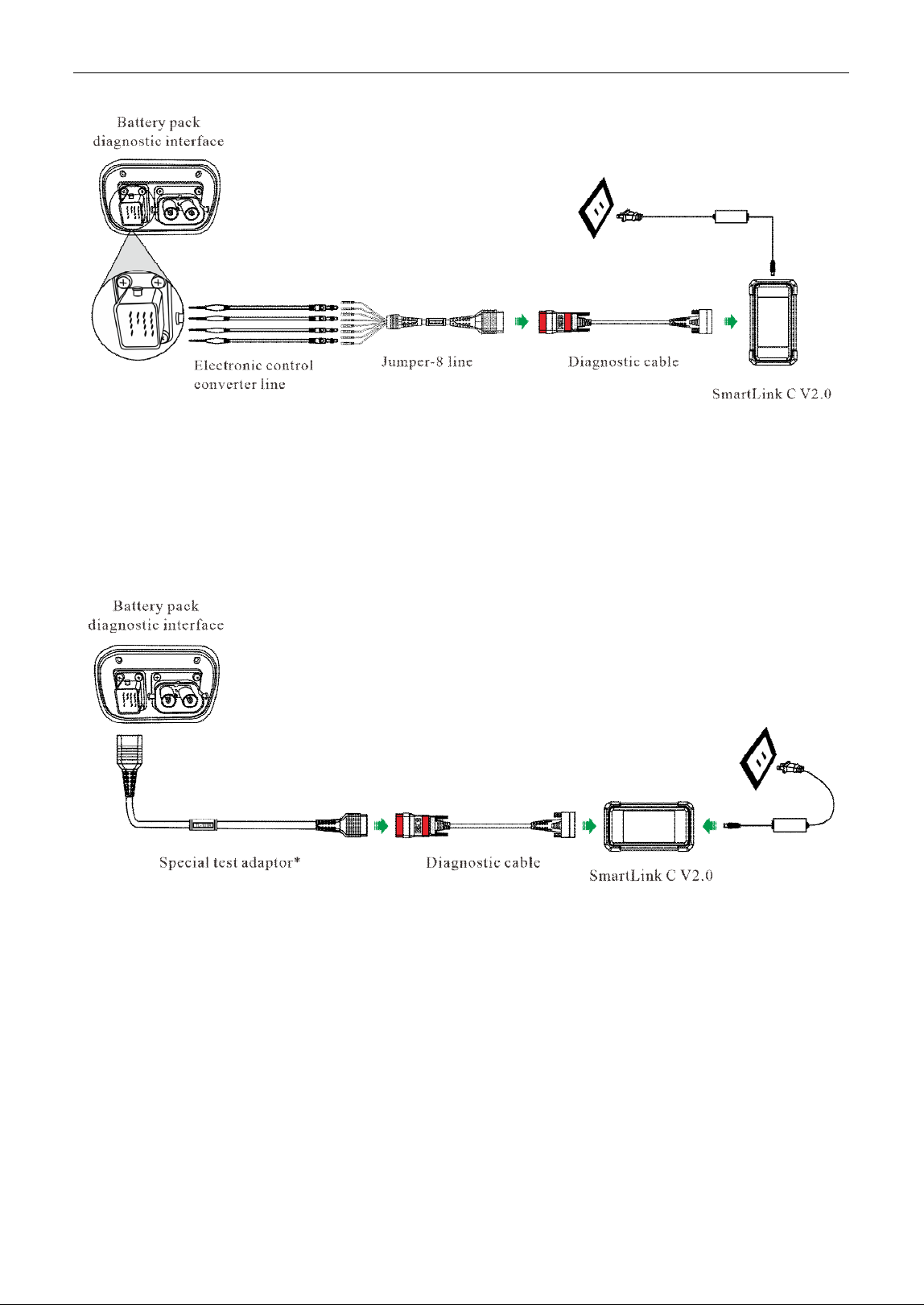
Mode 2:
Via Jumper
1. Connect one end of the diagnostic cable to the DB15 diagnostic connector of the SmartLink C V2.0 device,
and the other end to OBD-16 connector of the Jumper-8 line (sold separately).
2. Tap the icon shown on the screen to view the detailed connection prompts. Follow the onscreen instructions
to connect the electronic control converter line (sold separately), diagnostic interface of battery pack and the
Jumper-8 line (Each pin of Jumper-8 line has clear signal definition).
3. It is suggested that SmartLink C V2.0 device is connected to an external power source.
LAUNCH
30
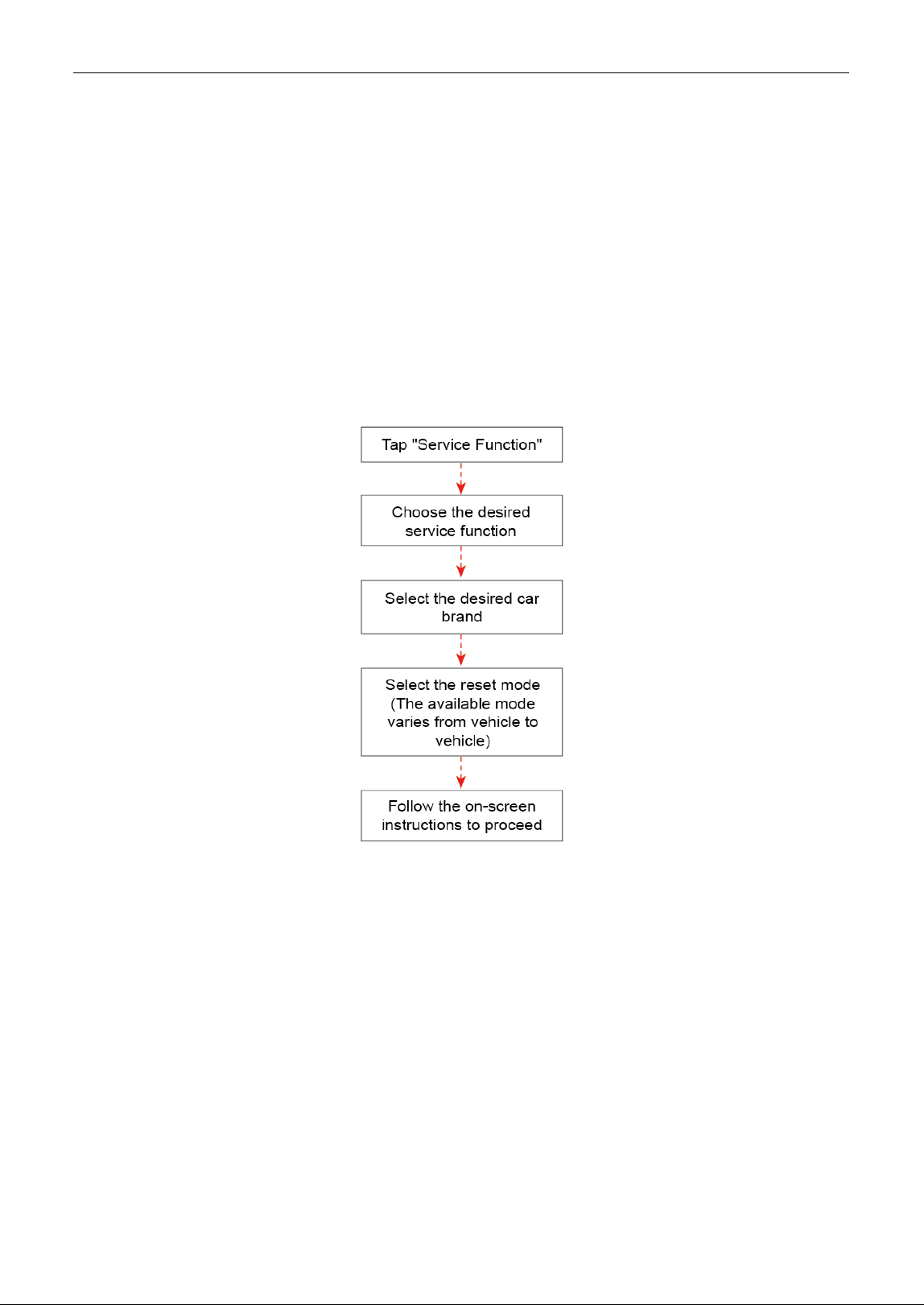
Mode 3:
Via Specific test adaptor
1. Connect one end of the diagnostic cable to the DB15 diagnostic connector of the SmartLink C V2.0 device,
and the other end to OBD-16 connector of the specific test adaptor (sold separately).
2. Plug the other end of the specific test adaptor to the diagnostic socket of the battery pack.
3. It is suggested that SmartLink C V2.0 device is connected to an external power source.
The specific test adaptor for battery pack varies with vehicle models/battery brands and the screen will prompt
corresponding test adaptor model for current test.
5.5 Feedback
This function enables you to send the feedback of your diagnostic problems to us for further analysis
and troubleshooting.
There are 3 options:
1). Feedback: To send a tested vehicle diagnostic feedback.
2). History: To view all diagnostic feedback records.
3). Offline list: To view all diagnostic logs that have failed to be submitted, which will be uploaded again
to the remote server automatically once the tablet gets the stable network.
5.6 Diagnostic History
This function enables users to directly get access to the previously tested vehicle’s diagnostic records

LAUNCH
31
in details, so users can resume from the last operation, without starting from scratch.
Tap Diagnostic History on the Job menu screen, all diagnostic records will be listed on the screen in
date sequence.
LAUNCH
32
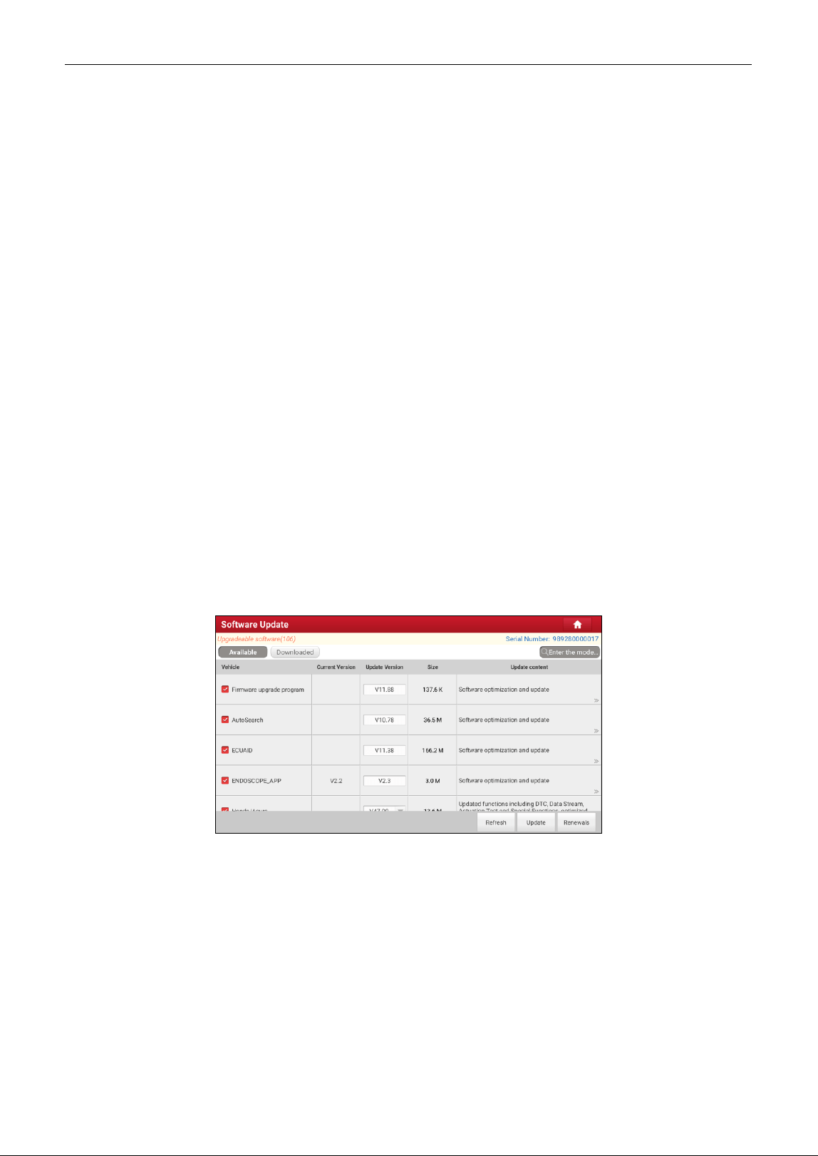
6 Service Function (Reset)
It offers coding, reset, relearn and more service functions, to help vehicles get back to functional status
after repair or replacement. Available tests vary by vehicle manufacturer, year, and model.
Due to continuing improvements, the available service functions are subject to change at any time. To
enjoy more service functions, you are suggested to check for updates on a regular basis.
There are two methods to reset service lamp: Manual Reset or Auto Reset. Auto Reset follows the principle
of sending command from the tool to vehicle’s ECU to do resetting. While using Manual Reset, users just
follow the on- screen instructions to select appropriate execution options, enter correct data or values,
and perform necessary actions, the system will guide you through the complete performance for various
service operations.
LAUNCH
33
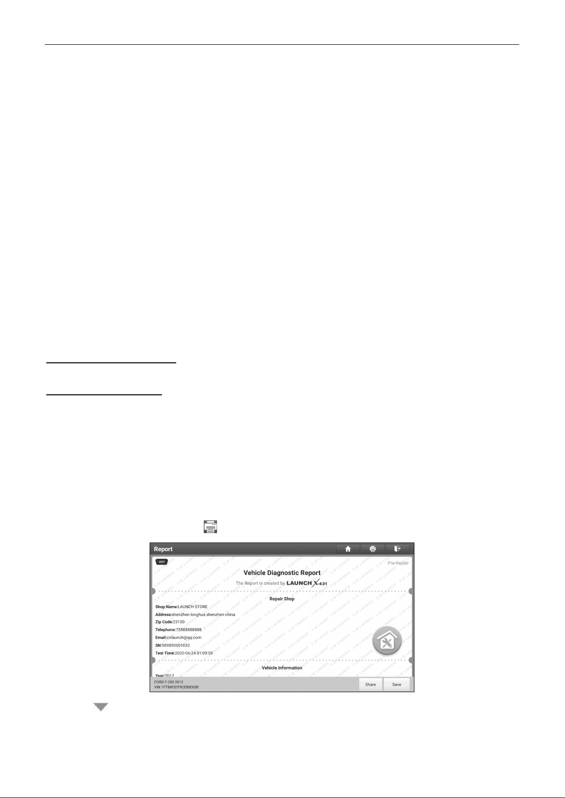
7 Software Update
This module enables you to update the diagnostic software & App and frequently used software.
7.1 Update Diagnostic Software & APP
Go to Software Update on the Job Menu and tap the Downloaded tab.
The Available tab displays a list of software that can be updated. Under it, all software is categorized
into three kinds:
• Common software: mainly includes some common apps that are associated with the diagnostic
app. The software of this kind always stays at the top of the list, which can be deselected manually
(excluding the system app, such as firmware and ECU aid).
• Frequently used vehicle software: refers to the diagnostic software that is frequently used,
including the vehicle diagnostic software and Reset software. It is generally displayed following the
Common software list.
• Other vehicle software: refers to the diagnostic software that is rarely used or never used. It is
generally displayed following the Frequently used software list.
1). If the user does not download any diagnostic software during the sign-up process, all diagnostic
software is selected by default. Tap Update to start downloading.
2). If the user downloaded all/some vehicle software during the sign-up process and had it serviced for
a long period of time, only the frequently used software is selected. Tap Update to start
downloading. Other vehicle software that is rarely used will also be listed under the Available tab,
but it is not selected at default.
To download certain software that is not frequently used, check the box before the vehicle model. Tap
Update to start downloading it.
After downloading is finished, the software packages will be installed automatically.
7.2 Update Frequently Used software
If the user only intends to update the frequently used software, go to Software Update and tap the
Downloaded tab.

LAUNCH
34
Tap Update to start downloading. Once download is finished, the software packages will be installed
automatically.
7.3 Renew Subscription
If the software subscription is due or expires, the system will prompt you to renew your subscription.
Tap Renewal to open the Mall, and then follow the on-screen prompts to finish the subscription.

LAUNCH
35
8 Toolbox
This function includes the following add-on modules: TPMS, ADAS, Oscilloscope, Sensor simulator,
BST360 Battery Tester, Immobilizer programmer, Videoscope, Current clamp, Multimeter, Insulation
Tester, Key programmer and more.
Each module consists of two parts: hardware and app. These modules cannot work properly on the
tablet, which need to work with the specific compatible hardware (sold separately). For detailed
operations, refer to the User Manual of each module.
8.1 TPMS
This module allows you to configure the tablet as TPMS activation & diagnostic tool, which provides the
ability to trigger TPMS sensor, program TPMS sensor, perform the relearning procedure. It needs to
work with the compatible TSGUN device (sold separately).
For more details, please refer to the User Manual included with the module.
8.2 ADAS (Calibration)
This module enables you to effectively and accurately calibrate a wide range of camera-based &
radar-based driver assistance systems, e.g. the front camera for the lane departure warning system,
the radar sensor for the ACC (Adaptive Cruise Control) or the camera for adaptive headlights. It needs
to work with the specific ADAS calibration tool (sold separately).
For more details, please refer to the User Manual included with the module.
8.3 Oscilloscope
This module can make the auto repair technician quickly judge the faults on automotive electronic
equipment and wiring. It needs to work with the specific Scopebox (sold separately).
For more details, please refer to the User Manual included with the module.
8.4 Sensor Simulator
This module is specially designed to diagnose and simulator vehicle sensor faults quickly and
conveniently. It needs to work with the compatible S2-2 Sensorbox (sold separately).
For more details, please refer to the User Manual included with the module.
8.5 Videoscope
This module allows you to check those unseen parts of engine, fuel tank, and braking system etc. It
needs to work with the compatible Videoscope (sold separately).
8.6 BST360 (Battery Tester)
This module allows you to fix battery detection faster and easier. It needs to work with the specific
Bluetooth battery tester (sold separately).
For more details, please refer to the User Manual included with the module.

LAUNCH
36
8.7 Multimeter
This module allows you to measure the physical parameters such as voltage, resistance, frequency etc.
It utilizes the same hardware as the EM101N.
For more details, please refer to the User Manual included with the EM101N.
8.8 Current Clamp
This module allows you to perform AC/DC current test and DC voltage test for traditional fuel cars and
new energy vehicles. It needs to work with the compatible current clamp (sold separately).
For more details, please refer to the User Manual included with the module.
8.9 Insulation Tester
The function enables you to complete the measurement of insulation resistance, voltage and other
parameters. It is suitable for users who measure and overhaul on-site power equipment and power
supply lines.
For more details, please refer to the User Manual included with the module.
8.10 Immobilizer Programmer
This module allows you to perform the read-write function for vehicle keys, EEPROM, MCU, and
EEPROM/FLASH of vehicle engine and gearbox ECU. It needs to work with the specific immobilizer
programmer (sold separately).
For more details, please refer to the User Manual included with the module.
8.11 Key Programmer
The function can identify car key chips and generate various types of chip models from super remotes,
read the remote control frequency of car keys, and generate remote control devices for different car
models from various types of super remotes. It needs to work with the compatible key programmer
(sold separately).
For more details, please refer to the User Manual included with the module.

LAUNCH
37
9 Diagnostic Widget
9.1 Vehicle Coverage
Use this item to check which vehicle models are supported on the tool.
9.2 CAN Bus Pin Detection
This function allows you to detect the voltage of the vehicle OBD II diagnostic socket pins and the
supported protocol types to help technicians judge the OBD
II diagnostic interface.
9.3 CANScope
This item can monitor vehicle CANBUS data and make it visual on the screen. Moreover it can also
check the problems existed in the CAN data, assisting you to analyze fault causes.
9.4 Diagnostic Software Clear
This item allows you to hide/clear the diagnostic software that is not frequently used.
Note: Removing software may completely delete the software from the tablet. If some software is not used
and the tablet runs out of space, you can use this feature to remove it. To re-download it, go to
Software Update
->
Available
.
9.5 Fix Connector Firmware/System
Use this item to upgrade and fix VCI firmware/system. During fixing, please do not cut power or switch
to other interfaces.
9.6 Data Stream Sample
This item allows you to manage the recorded data stream sample files.
9.7 DLC Voltage Check
This item performs a check of the vehicle’s battery to ensure the system is operating within acceptable
limits.
9.8 Reset MSVIN
This item can decode the VIN information of all ECUs installed on test vehicle and output all
inconsistent VINs.
9.9 Diagnostic History
When a vehicle diagnosis is performed, the tablet records the detailed diagnostic information. The
History function allows access to previously tested vehicle records. Testing can be resumed from the
previous operation without starting from scratch.
Tap Diagnostic History, all diagnostic records will be listed on the screen in date sequence.

LAUNCH
38
10 User Info
This function allows users to manage personal information and VCI.
10.1 My Report
This option is used to view, delete or share the saved reports.
Tap Report, there are total 3 options available.
In case the DTC result is saved on Read Trouble Code page, the files will be listed under Health
Reports tab.
If user records the running parameters while reading data stream, the tablet will save the file which
appears under Recorded Data tab.
Remote Reports lists all diagnostic reports generated in process of remote diagnosis.
10.2 VCI
This option allows you to manage all activated VCI devices.
If several VCI devices are activated on this tool, a list of VCIs will be displayed on the screen. Once you
choose the VCI device that belongs to other account, you have to log out, and then input the right
account to continue.
10.3 Activate VCI
This item lets you activate a new VCI.
10.4 Profile
Use this item to view and configure personal information.
• The profile description includes a ‘placeholder’ for a user photograph. Tap the user image to change
it.
• Tap > next to Upgrade Period to check the due date of all diagnostic software.
10.5 My Order
This item allows you to check the status of all your orders.
10.6 Change Password
This item allows you to modify your login password.
10.7 Login/Log out
To logout the current user ID, tap Log Out.
To login the system again, tap Login.
LAUNCH
39
11 Settings
It enables you to make some application settings and view software version information etc.
11.1 Units
It is designed to configure the measurement unit. Metric System and English System are available.
11.2 Shop information
This option lets you define your print information. It mainly includes Workshop, Address, Telephone,
Fax and License Plate.
Once you saved the print information, it will be entered automatically in the “Add Information” box every
time you save the diagnostic report.
11.3 Printer set
This option is designed to establish a wireless connection between the tablet and the Wi-Fi printer (sold
separately) while performing printing operations.
The App is compatible with the LAUNCH Wi-Fi Printer (sold separately) and System (external printer).
For LAUNCH Wi-Fi printer, refer to the User Manual included with the Wi-Fi printer to configure the
printer settings.
For other Wi-Fi printers,
Before printing, make sure the following conditions are met:
• The Wi-Fi printer is powered on and working normally.
• The print service plug-in associated with the printer is already installed on the tablet (Go to Google
Play or use the Browser to download and install it).
Follow the steps below to proceed:
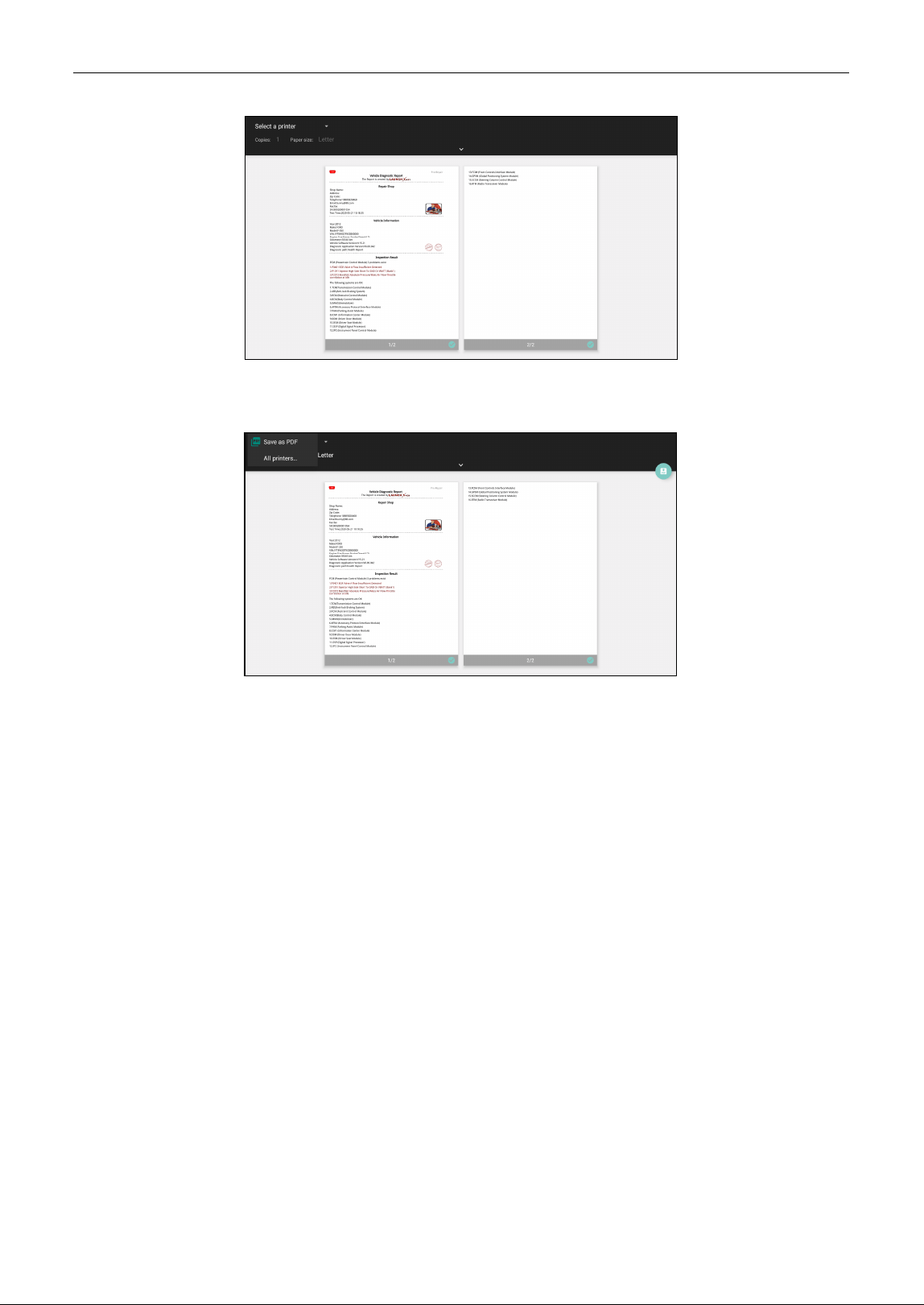
1. Set the default printer as System.
2. Set the Wi-Fi switch to Off.
3. On the report details page, tap .
4. Touch next to Select a printer on the upper left corner of the screen.
LAUNCH
40
5. Select All Printers -> Add printer and enable the installed printer service, the system starts
searching for all available Wi-Fi printers of the brand.
6. Select the desired Wi-Fi printer from the list. If the chosen Wi-Fi printer hotspot is open, the tablet
can connect it directly. If it is encrypted, a password may be required. Refer to the Wi-Fi printer user
manual to get the default password.
7. Now the printer is ready for printing.
8. Alternatively, you can also choose Save as PDF to save the current diagnostic report as a PDF file
for later printing.
11.4 Clear cache
This item is used to clear the App cache.
Tap Clear Cache, a pop-up window will appear on the screen. Tap OK to clear cache and the system
will restart the App.
11.5 Diagnostic software auto update
This option is used to set whether automatic update function is ON.
11.6 Device account management
This option is used to manage the authorized technician accounts. The added technician account
allows the VCI to be used by different users to log in the tool, which is convenient for multiple VCIs to
perform diagnostic service at the same time.
The newly added technician account has a one-year validity period. After the expiration, the VCI bound
LAUNCH
41
to the technician account cannot be used and the technician account will no longer enjoy the rights and
interests of the main account. The main account can modify the validity period of the sub-account.
There are two types of technician accounts: one is an existing account and the other is a newly created
account. The main account has the functions of adding and removing technician accounts, the
technician account can also be unbound from the main account.
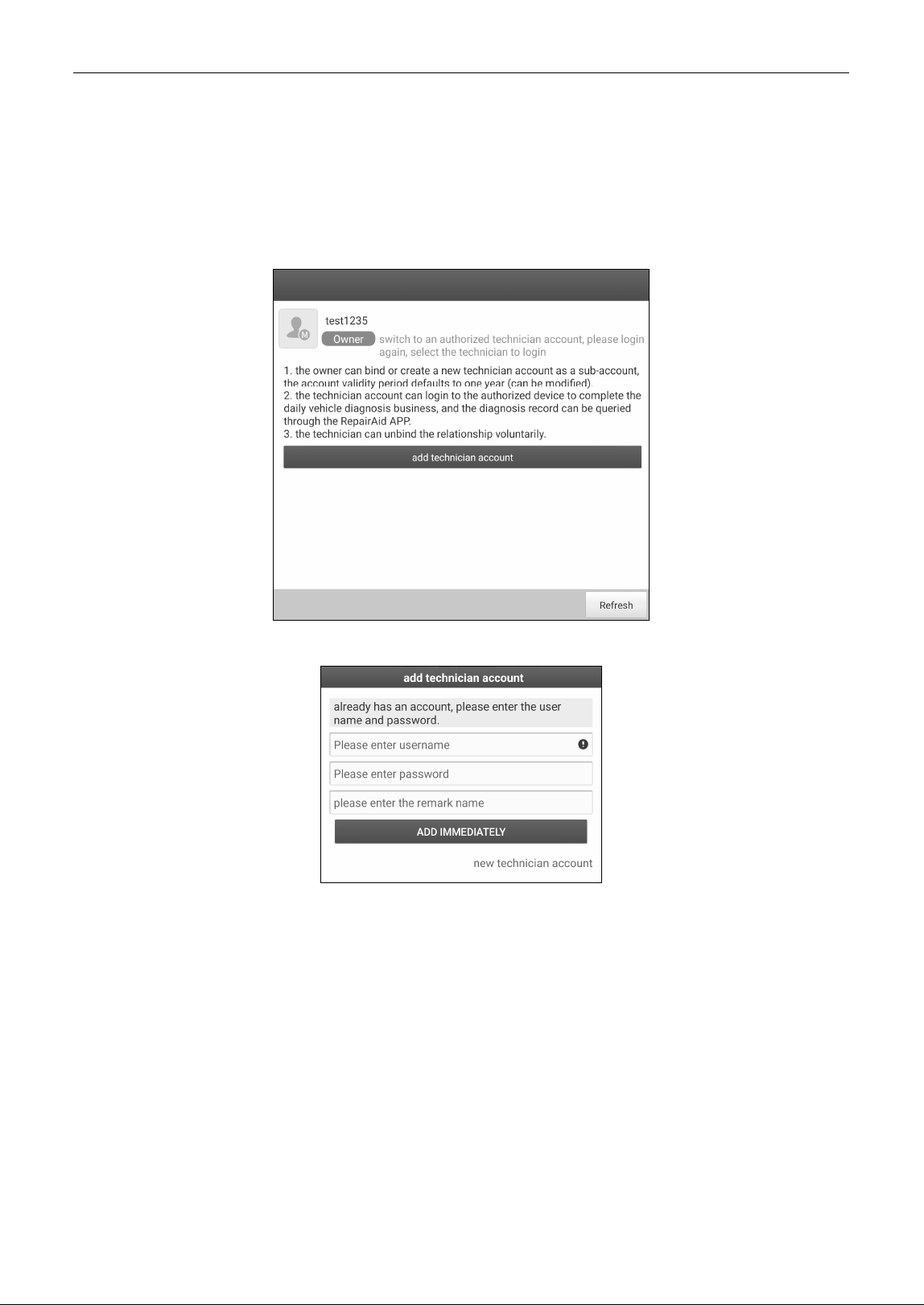
Tap Device account management, the following screen will appear:
Tap Add technician account, the following popup will appear:
• If you already have an account, please enter the user name and password. After inputting, tap Add
Immediately to add it as an authorized technician account.
• If you have not registered any account, tap New technician account. Enter the user name and
password, and then tap Add Immediately to add it as a technician account.
The new technician account can login the authorized scanner to complete the daily vehicle diagnosis
business, and the diagnosis record can be checked through the RepairAid App (can be downloaded in
Google Play).
After adding the technician account, tap Remove to unbind it from the main account; tap Change to
revise the validity period.
LAUNCH
42
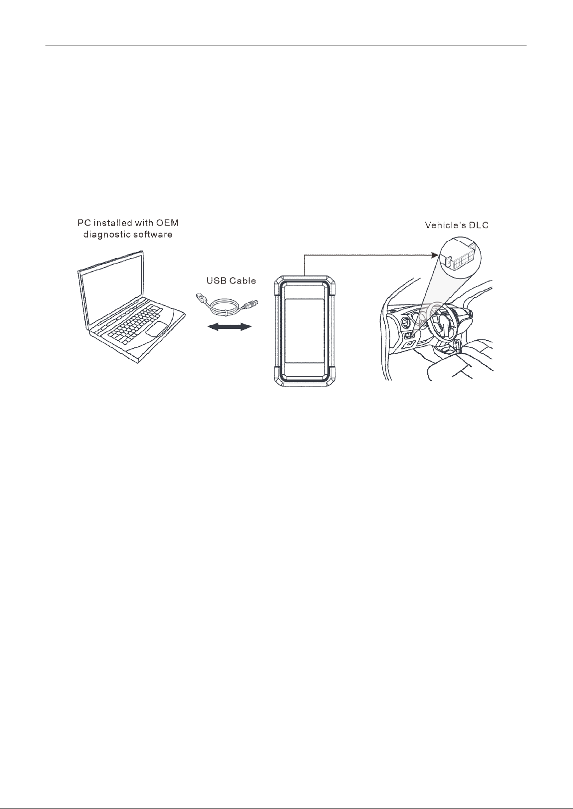
12 J2534 Reprogramming
Reprogramming is often the only solution for problems ranging from driveability and loss of power to
poor fuel economy and emissions related issues. SmartLink C makes it easy. The SmartLink C is a
communication interface supporting J2534 specifications for ECU reprogramming.
Except that the SmartLink C acts as a VCI device and a SmartLink dongle, it also can be used as a
J2534 PassThru device, working together with the PC installed with the OEM diagnostic software to
perform the J2534 reprogramming. In this case, the PC needs to install with the LAUNCH's J2534 tool,
which can be downloaded from https://en.cnlaunch.com.

LAUNCH
43
13 FAQ
13.1 About diagnostic tablet
1. How to save power?
1. Please turn off the screen while the tool keeps idle.
2. Set a shorter standby time.
3. Decrease the brightness of the screen.
4. If WLAN connection is not required, please turn it off.
2. Communication error with vehicle ECU?
Please confirm:
1. Whether the VCI device is correctly connected.
2. Whether ignition switch is ON.
3. If all checks are normal, send vehicle year, make, model and VIN number to us using Feedback
feature.
3. Failed to enter into vehicle ECU system?
Please confirm:
1. Whether the vehicle is equipped with this system.
2. Whether the VCI device is correctly connected.
3. Whether ignition switch is ON.
4. If all checks are normal, send vehicle year, make, model and VIN number to us using Feedback
feature.
4. How to download the diagnostic app after resetting the tablet?
Note: Before registration, please make sure the network is properly connected.
After the tablet has been successfully reset, follow the steps below to download the App:
1. Launch the browser and the default official Launch website opens (If a blank page pops up, just type
in www.x431.com in the input bar).
2. Tap Login, input the username and password and tap Log In.
3. Make sure that the serial number is correct, tap APP application program and tap the Download
icon to start downloading.
4. After the download is complete, follow the on-screen instructions to install it.
5. After installation, use the existing username and password to login and go to update center to
download the diagnostic software.
5. What to do if the language of vehicle diagnostic software does not match the system
language?
English is the default system language of the tool. After the system language is set to the preference
language, please go to the update center to download the vehicle diagnostic software of the
corresponding language.
If the downloaded diagnostic software is still displayed in English, it indicates that the software of the

LAUNCH
44
current language is under development.
6. How to retrieve the login password?
Please follow below steps to proceed in case you forgot the login password:
1. Tap the application icon on the home screen to launch it.
2. Tap Login on the upper right corner of the screen.
3. Tap Retrieve password.
4. Input product S/N and follow the on-screen prompts to retrieve the password.
13.2 About SmartLink Diag.
1. What’s network conditions is required for SmartLink Diag.?
The remote SmartLink Diag. operation requires a network broadband of 100MB or above.
2. What does the word “Delay” displayed on the SmartLink C screen mean?
The Delay (network delay) indicates the state of the network communication, which can be regarded as
a reference since different vehicles require different delays. Different colors represent different delay
status. There are three states of network delay:
Green: Indicates a shorter network delay. In this case, it has a higher success rate of remote
communication.
Yellow: Indicates a medium network delay. In this case, it has a medium success rate of remote
communication.
Red: Indicates a longer network delay. In this case, it has a lower success rate of remote
communication and remote ECU reprogramming operations are not suggested.
3. My network delay is so long.
Please check the following possible reasons:
1. The greater distance between the SmartLink B2.0/SmartLink B and SmartLink C V2.0 dongle causes
a longer network delay.
2. There are too many network communication nodes that the data communication passes by, which
may cause a longer network delay.
3. Check if the network is poor and data communication speed is slow.
4. Some systems of some old vehicles cannot be tested
The SmartLink C V2.0 dongle supports CAN2.0/CANFD/DoIP communication protocols, but some old
vehicle uses K-Line communication protocol.
5. Is it necessary to re-ignite the car after the diagnostic system starts working?
For the sake of some vehicle's conditions, the re-ignition will provide you a more detailed analysis after
OBD diagnosis.

LAUNCH
45
Warranty
THIS WARRANTY IS EXPRESSLY LIMITED TO PERSONS WHO PURCHASE LAUNCH PRODUCTS
FOR PURPOSES OF RESALE OR USE IN THE ORDINARY COURSE OF THE BUYER’S
BUSINESS.
LAUNCH electronic product is warranted against defects in materials and workmanship for one year
from date of delivery to the user.
This warranty does not cover any part that has been abused, altered, used for a purpose other than for
which it was intended, or used in a manner inconsistent with instructions regarding use. The exclusive
remedy for any automotive meter found to be defective is repair or replacement, and LAUNCH shall not
be liable for any consequential or incidental damages.
Final determination of defects shall be made by LAUNCH in accordance with procedures established
by LAUNCH. No agent, employee, or representative of LAUNCH has any authority to bind LAUNCH to
any affirmation, representation, or warranty concerning LAUNCH automotive meters, except as stated
herein.
Disclaimer
The above warranty is in lieu of any other warranty, expressed or implied, including any warranty of
merchantability or fitness for a particular purpose.
Purchase Order
Replaceable and optional parts can be ordered directly from your LAUNCH authorized tool supplier.
Your order should include the following information:
Order quantity
Part number
Part name
Customer Service
If you have any questions on the operation of the unit, please contact the seller,
or customer service
center
:
Statement:
LAUNCH reserves the rights to make any change to product designs and specifications without notice.
The actual object may differ a little from the descriptions in the manual in physical appearance, color
and configuration. We have tried our best to make the descriptions and illustrations in the manual as
accurate as possible, and defects are inevitable, if you have any question, please contact local dealer
or after-sale service center of LAUNCH, LAUNCH does not bear any responsibility arising from
Website: https://en.cnlaunch.com
Phone: 1-888-756-2936
Email: Tech_[email protected]
misunderstandings.