
Version: V1.00.000
Revised date: 04-03-2023

LAUNCH
i
Trademarks
LAUNCH is a registered trademark of LAUNCH TECH CO., LTD. in China and
other countries. All other marks are trademarks or registered trademarks of their
respective holders.
Copyright Information
Copyright © 2022 by LAUNCH TECH CO., LTD. (also called LAUNCH for short).
All rights reserved. No part of this publication may be reproduced, stored in a
retrieval system, or transmitted in any form or by any means, electronic,
mechanical, photocopying and recording or otherwise, without the prior written
permission.
Statement: LAUNCH owns the complete intellectual property rights for the
software used by this product. For any reverse engineering or cracking actions
against the software, LAUNCH will block the use of this product and reserve the
right to pursue their legal liabilities.
Disclaimer of Warranties and Limitation of Liabilities
All information, illustrations, and specifications in this manual are based on the
latest information available at the time of publication.
The right is reserved to make changes at any time without notice. We shall not
be liable for any direct, special, incidental, indirect damages or any economic
consequential damages (including the loss of profits) due to the use of the
document.

LAUNCH
ii
Using This Manual
This manual contains device usage instructions.
Some illustrations shown in this manual may contain modules and optional
equipment that are not included in your system.
The following conventions are used.
Bold Text
Bold text is used to highlight selectable items such as buttons and menu options.
Example:
Tap
OK
.
Notes and Important Messages
Notes
A NOTE provides helpful information such as additional explanations, tips, and
comments.
Example:
Note: Remember to remove the VCI connector from the vehicle’s DLC after use.
Warning
Warning indicates a hazardous situation which, if not avoided, could result in
minor or moderate injury to the operator or to bystanders.
Example:
Warning: Retrieving and using DTCs for troubleshooting vehicle operation is only
one part of an overall diagnostic strategy. Never replace a part based only on the DTC
definition. Each DTC has a set of testing procedures, instructions and flow charts that
must be followed to confirm the location of the problem. This information can be found
in the vehicle’s service manual.
Danger
Danger indicates an imminently or potentially hazardous situation which, if not
avoided, could result in death or serious injury to the operator or to bystanders.
Example:
Danger: If you must drive the vehicle in order to perform a troubleshooting
procedure, always have a second person help you. Trying to drive and operate the
diagnostic tool at the same time is dangerous, and could cause a serious traffic accident.

LAUNCH
iii
Illustrations
Illustrations used in this manual are samples, the actual testing screen may vary
for each vehicle being tested. Observe the menu titles and on-screen
instructions to make correct option selection.
Important Safety Precautions
To avoid personal injury, property damage, or accidental damage to the product,
read all of the information in this section before using the tool.
DANGER
• When an engine is operating, keep the service area well-ventilated or attach
a building exhaust removal system to the engine exhaust system. Engines
produce various poisonous compounds (hydrocarbon, carbon monoxide,
nitrogen oxides, etc.) that cause slower reaction time and result in death or
serious personal injury.
• Please use the included battery and power adaptor. Risk of explosion if the
battery is replaced with an incorrect type.
• DO NOT attempt to operate the tool while driving the vehicle. Have second
personal operate the tool. Any distraction may cause an accident.
WARNING
Always perform automotive testing in a safe environment.
Do not connect or disconnect any test equipment while the ignition is on or
the engine is running.
Before starting the engine, put the gear lever in the Neutral position (for
manual transmission) or in the Park (for automatic transmission) position to
avoid injury.
NEVER smoke or allow a spark or flame in vicinity of battery or engine. Do
not operate the tool in explosive atmospheres, such as in the presence of
flammable liquids, gases, or heavy dust.
Keep a fire extinguisher suitable for gasoline/chemical/electrical fires nearby.
Wear an ANSI-approved eye shield when testing or repairing vehicles.
Put blocks in front of the drive wheels and never leave the vehicle unattended
while testing.
Use extreme caution when working around the ignition coil, distributor cap,

LAUNCH
iv
ignition wires and spark plugs. These components create hazardous voltage
when the engine is running.
To avoid damaging the tool or generating false data, please make sure the
vehicle battery is fully charged and the connection to the vehicle DLC (Data
Link Connector) is clear and secure.
Automotive batteries contain sulfuric acid that is harmful to skin. In operation,
direct contact with the automotive batteries should be avoided. Keep the
ignition sources away from the battery at all times.
Keep the tool dry, clean, free from oil, water or grease. Use a mild detergent
on a clean cloth to clear the outside of the equipment when necessary.
Keep clothing, hair, hands, tools, test equipment, etc. away from all moving or
hot engine parts.
Store the tool and accessories in a locked area out of the reach of children.
Do not use the tool while standing in water.
Do not expose the tool or power adapter to rain or wet conditions. Water
entering the tool or power adaptor increases the risk of electric shock.
This tool is a sealed unit. There are no end-user serviceable parts inside. All
internal repairs must be done by an authorized repair facility or qualified
technician. If there is any inquiry, please contact the dealer.
Keep the tool far away from magnetic devices because its radiations can
damage the screen and erase the data stored on the tool.
Do not attempt to replace the internal rechargeable lithium battery. Contact
the dealer for factory replacement.
Do not disconnect battery or any wiring cables in the vehicle when the ignition
switch is on, as this could avoid damage to the sensors or the ECU.
Do not place any magnetic objects near the ECU. Disconnect the power
supply to the ECU before performing any welding operations on the vehicle.
Use extreme caution when performing any operations near the ECU or
sensors. Ground yourself when you disassemble PROM, otherwise ECU and
sensors can be damaged by static electricity.
When reconnecting the ECU harness connector, be sure it is attached firmly,
otherwise electronic elements, such as ICs inside the ECU, can be damaged.

LAUNCH
v
FCC Statement
Any Changes or modifications not expressly approved by the party responsible
for compliance could void the user’s authority to operate the equipment.
This device complies with part 15 of the FCC Rules. Operation is subject to the
following two conditions: (1) This device may not cause harmful interference,
and (2) this device must accept any interference received, including interference
that may cause undesired operation.
Note: This equipment has been tested and found to comply with the limits for a
Class B digital device, pursuant to Part 15 of the FCC Rules. These limits are
designed to provide reasonable protection against harmful interference in a
residential installation.
This equipment generates, uses, and can radiate radio frequency energy, and if
not installed and used in accordance with the instructions, may cause harmful
interference to radio communications. However, there is no guarantee that
interference will not occur in a particular installation. If this equipment does
cause harmful interference to radio or television reception, which can be
determined by turning the equipment off and on, the user is encouraged to try to
correct the interference by one or more of the following measures:
- Reorient or relocate the receiving antenna.
- Increase the separation between the equipment and receiver.
- Connect the equipment into an outlet on a circuit different from that to which
the receiver is connected.
- Consult the dealer or an experienced radio/TV technician for help.

LAUNCH
vi
IC Warning
This device contains licence-exempt transmitter(s) that comply with Innovation,
Science and Economic Development Canada's licence-exempt RSS(s).
Operation is subject to the following two conditions:
(1) This device may not cause interference.
(2) This device must accept any interference, including interference that may
cause undesired operation of the device.
Le present appareil est conforme aux CNR d'Industrie Canada applicables aux
appareils radio exempts de licence. L'exploitation est autorisee aux deux
conditions suivantes:
(1) l'appareil ne doit pas produire de brouillage, et
(2) Iutilisateur de l'appareil doit accepter tout brouillage radioelectrique subi,
meme si le broullage est susceptible d'en compromettre le fonctionnement.
This device has been designed and manufactured to comply with the limits for
exposure to RF energy set by the Industry Canada (IC) and the European Union
and other countries.
Model: OADD-PO0805A
The product and the distance from the human body during normal use is 0mm,
RF exposure limit is 1.6 W/Kg. The highest reported RF exposure value to
0.257W/Kg.

LAUNCH
vii
TABLE OF CONTENTS
1 Introduction .................................................................................................. 1
1.1 Product Profile ........................................................................................ 1
1.2 Components & Controls ......................................................................... 2
1.2.1 Display Tablet .................................................................................. 2
1.2.2 VCI Connector................................................................................. 4
1.3 Technical Parameters ............................................................................. 6
1.4 Package List ........................................................................................... 6
2 Initial Use ...................................................................................................... 8
2.1 Charging & Turning On ........................................................................... 8
2.2 Screen Layout ........................................................................................ 8
2.3 Basic Gestures ....................................................................................... 8
2.4 Change System Language ..................................................................... 9
2.5 Adjust Brightness.................................................................................... 9
2.6 Set Standby Time ................................................................................... 9
2.7 Network Setup ...................................................................................... 10
3 Getting Started ............................................................................................ 11
3.1 Register & Update ................................................................................ 11
3.2 Job Menu.............................................................................................. 13
4 Connections ................................................................................................ 16
4.1 Preparation ........................................................................................... 16
4.2 Vehicle Connection............................................................................... 16
4.2.1 OBD II vehicle Connection ............................................................ 17
4.2.2 Non-OBD II vehicle Connection..................................................... 17
5 Diagnosis .................................................................................................... 19
5.1 Intelligent Diagnose .............................................................................. 19
5.2 Local Diagnose ..................................................................................... 22
5.2.1 Health Report (Quick Test) ............................................................ 28
5.2.2 System Scan ................................................................................. 32
5.2.3 System Selection .......................................................................... 32
5.3 Remote Diagnose ................................................................................. 43

LAUNCH
viii
5.3.1 Add Friends ................................................................................... 43
5.3.2 Start Instant Messaging ................................................................. 45
5.3.3 Launch Remote Diagnosis (Device-To-Device) ............................. 46
5.3.4 Launch Remote Diagnosis (Device-To-PC) ................................... 49
5.4 Feedback.............................................................................................. 51
5.5 Diagnostic History................................................................................. 52
6 Service (Reset) Function............................................................................ 53
6.1 Maintenance Light Reset (Oil Reset) .................................................... 53
6.2 Electronic Parking Brake Reset (BRAKE RESET) ................................ 53
6.3 Steering Angle Reset (SAS Reset) ....................................................... 54
6.4 ABS Bleeding ....................................................................................... 54
6.5 Crank Position Sensor Adaptive Learning (GEAR LEARN) .................. 54
6.6 Anti-theft Matching (IMMO) ................................................................... 54
6.7 Injector Coding (INJECTOR) ................................................................ 55
6.8 Battery Matching (BAT. RESET) .......................................................... 55
6.9 DPF Regeneration (DPF REG.) ............................................................ 55
6.10 Throttle Matching (ELEC. THROTTLE RLRN) .................................... 56
6.11 Gearbox Matching (GEARBOX) ......................................................... 56
6.12 Headlight Matching (AFS RESET) ...................................................... 56
6.13 Sunroof Initialization (SUNROOF) ...................................................... 56
6.14 Suspension Level Calibration (SUS RESET) ...................................... 56
6.15 EGR Adaption .................................................................................... 56
6.16 Seats Calibration ................................................................................ 57
6.17 Tyre Reset .......................................................................................... 57
6.18 Coolant Bleed ..................................................................................... 57
6.19 AdBlue Reset ..................................................................................... 57
6.20 NOx Sensor Reset .............................................................................. 57
6.21 AC System Relearn/Initialization ........................................................ 57
6.22 High Voltage Battery Detection (HIGH VOLTAGE BATTERY) ........... 57
6.23 Windows Calibration ........................................................................... 58
6.24 Language Change .............................................................................. 58
6.25 A/F Reset ........................................................................................... 58

LAUNCH
ix
6.26 Transport Mode .................................................................................. 58
6.27 Stop/Start Reset ................................................................................. 58
6.28 Intelligent Cruise Control System Reset ............................................. 58
6.29 Engine Power Balance Monitoring ...................................................... 59
6.30 Gas Particulate Filter (GPF) Regeneration ......................................... 59
6.31 Motor Angle Calibration ...................................................................... 59
6.32 Tire Pressure Reset (TPMS RESET) .................................................. 59
6.33 IMMO Programming ........................................................................... 59
6.34 Turbocharging Matching ..................................................................... 59
6.35 Clutch Matching .................................................................................. 59
6.36 FRM Matching .................................................................................... 60
6.37 ECU Reset ......................................................................................... 60
7 Software Update ......................................................................................... 61
7.1 Update Diagnostic Software & APP ...................................................... 61
7.2 Update Frequently Used Software ........................................................ 62
7.3 Renew Subscription .............................................................................. 62
8 Add-on Modules ......................................................................................... 64
8.1 ADAS (Calibration) ............................................................................... 64
8.2 TPMS ................................................................................................... 64
8.3 Oscilloscope ......................................................................................... 64
8.4 S2-2 Sensorbox .................................................................................... 64
8.5 S2-2 Multimeter .................................................................................... 64
8.6 BST360 (Battery Tester) ....................................................................... 65
8.7 Immobilizer Programmer ...................................................................... 65
8.8 Videoscope ........................................................................................... 65
9 User Info ...................................................................................................... 66
9.1 My Report ............................................................................................. 66
9.2 VCI ....................................................................................................... 66
9.3 VCI Management.................................................................................. 66
9.4 Activate VCI .......................................................................................... 66
9.5 Firmware Fix ......................................................................................... 67

LAUNCH
x
9.6 Sample ................................................................................................. 67
9.7 My Order .............................................................................................. 67
9.8 Subscription Renewal Card .................................................................. 67
9.9 Profile ................................................................................................... 67
9.10 Change password............................................................................... 68
9.11 Settings .............................................................................................. 68
9.11.1 Units ............................................................................................ 68
9.11.2 Shop Information ......................................................................... 68
9.11.3 Printer Set ................................................................................... 69
9.11.4 Orientation ................................................................................... 70
9.11.5 Clear Cache ................................................................................ 71
9.11.6 About ........................................................................................... 71
9.11.7 Diagnostic Software Auto Update ................................................ 71
9.11.8 Device Account Management ...................................................... 71
9.11.9 Login/Logout ................................................................................ 73
9.12 Diagnostic Software Clear .................................................................. 73
10 FAQ ............................................................................................................ 74

LAUNCH
1
1 Introduction
1.1 Product Profile
It inherits from LAUNCH’s advanced diagnosing technology and is characterized
by covering a wide range of vehicles, featuring powerful functions, and providing
precise test result.
Through the simple Bluetooth communication between VCI (Vehicle
Communication Interface) device and the display tablet, it achieves full car
model and full system vehicle trouble diagnosis, which include Reading DTCs,
Clearing DTCs, Reading Data Stream, Actuation Test and Special Functions.
Moreover, taking advantage of the mobile Internet, it also integrates One-click
Update, Remote Diagnosis and Repair Data, which helps to diagnose vehicle
issues more efficiently, and greatly increase customer’s retention.
It has the following features:
Intelligent Diagnose: This module allows you to use the VIN information of the
currently identified vehicle to access its data (including vehicle information,
historical diagnostic records) from the cloud server to perform quick test,
eliminating guesswork and step-by-step manual menu selection.
Local Diagnose: Follow the on-screen prompts to start diagnostic session
step by step. Diagnosis functions include: Read DTCs, Clear DTCs, Read
Data Stream, Special Functions etc.
Remote Diagnose: This option aims to help repair shops or technicians
launch instant messaging and remote diagnosis, making the repair job getting
fixed faster.
Service Function: It offers coding, reset, relearn and more service functions, to
help vehicles get back to functional status after repair or replacement.
One-click Update: Lets you update your diagnostic software online.
ADAS calibration: Allows you to perform Advanced Driver Assistance System
(ADAS) calibration operations. This function needs to be activated before
normal use and only works with the specific ADAS calibration tool (sold
separately).
TPMS: Configures the tool as a professional Tire Pressure Monitoring
System (TPMS) service tool. It needs to work with the TSGUN device (sold

LAUNCH
2
separately) to perform all kinds of various TPMS functions.
Mall: Enables you to subscribe some extra software or service functions that
are not integrated in the tool online.
Diagnostic History: This function provides a quick access to the tested
vehicles and users can choose to view the test report or resume from the last
operation, without starting from scratch.
Feedback: Enables you to submit the vehicle issue to us for analysis and
troubleshooting.
Vehicle Coverage: Quick dial to view the vehicle models that the tool covers.
Add-on modules: Optional. BST 360 Battery Tester, S2-2 Sensorbox,
Multimeter and Videoscope etc. are available as add-on modules, extending
the functions of the tool.
1.2 Components & Controls
There are two main components to the diagnostic system:
Display Tablet – the central processor and monitor for the system (See
Chapter “1.2.1”).
VCI Device – the device for accessing vehicle data (See Chapter “1.2.2”).
1.2.1 Display Tablet
The tablet acts as the central processing system, which is used to receive and
analyze the live vehicle data from the VCI device and then output the test result.
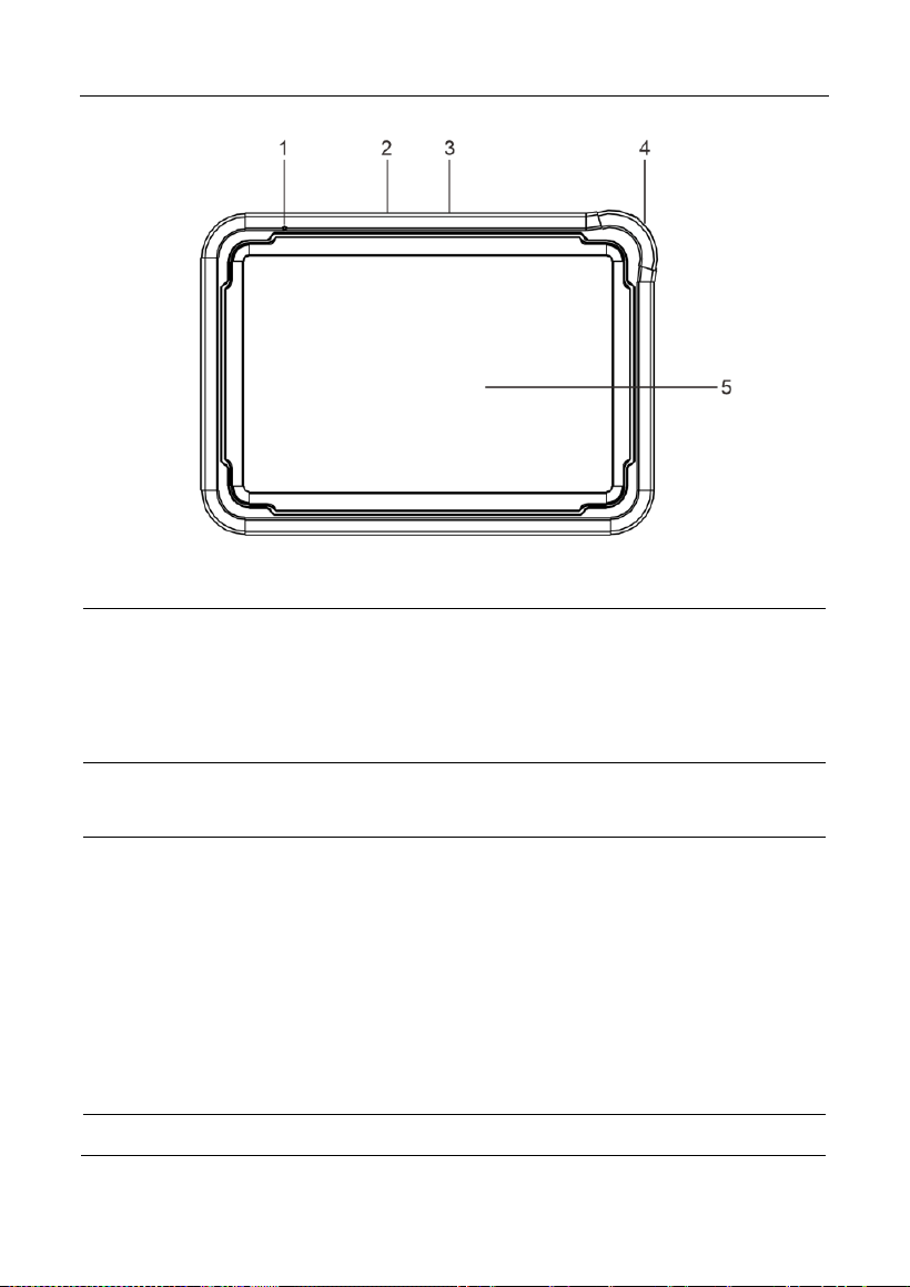
LAUNCH
3
1
Microphone
2
Type-A USB Port
• Connects to the VCI connector to perform
vehicle diagnosis via the USB cable.
• Connects to compatible add-on modules
(such as Videoscope) or USB storage
devices.
3
Type-C USB Port
• Connects to AC outlet for charging.
• Connects to PC for data exchange.
4
POWER Key
In Off mode, press it for 3 seconds to turn the
tablet on.
In On mode:
• Press it once to activate the LCD if the LCD
is off. Press it once to turn off the LCD if the
LCD lights up.
• Press and hold it for 3 seconds to turn it off.
• Press and hold it for 8 seconds to perform
forced shutdown.
5
LCD Screen
Indicates the test result.
LAUNCH
4
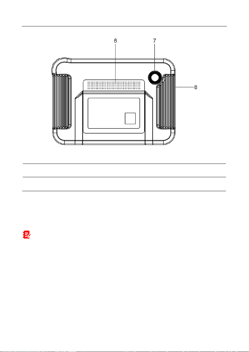
6
Speakers
7
Rear Camera
8
Microphone
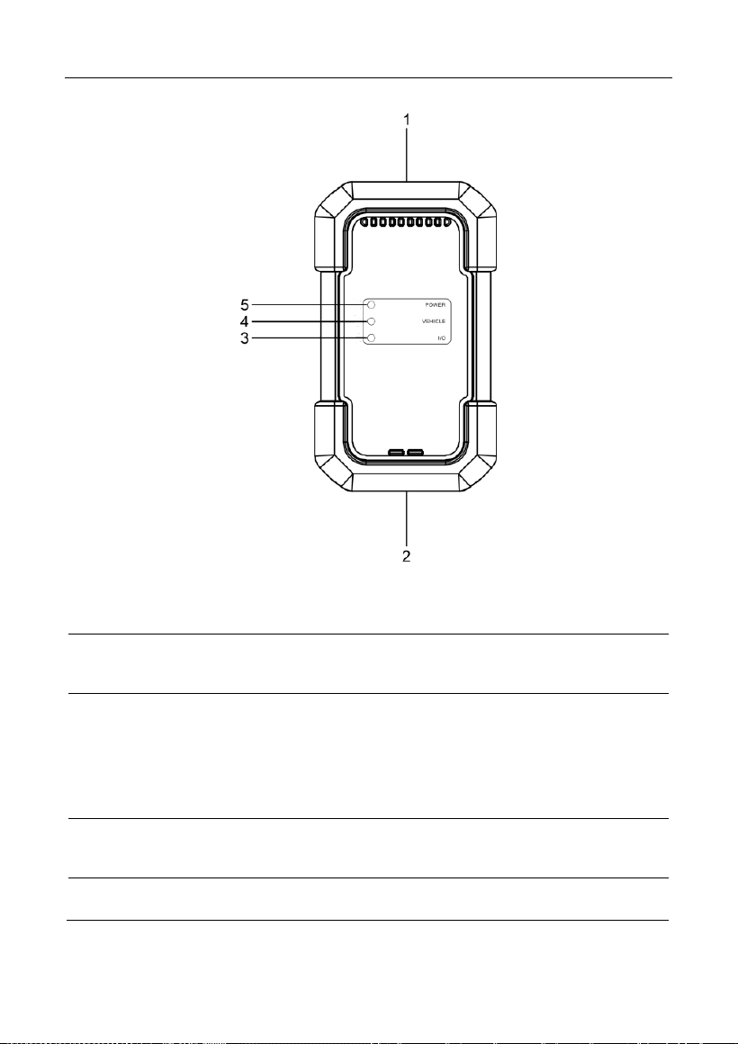
1.2.2 VCI Connector
The VCI connector works as a vehicle communication interface device, which is
used to connect to the vehicle’s DLC (Data Link Connector) socket via the
diagnostic cable to read the vehicle data and then send it to the tablet.
Note: Remember to remove the VCI connector from the vehicle’s DLC after use.
LAUNCH
5
1
OBD-15 diagnostic
connector
Connects on vehicle’s OBD II DLC via the
diagnostic cable.
2
USB port
Connects the VCI to the tablet to perform
vehicle diagnosis via USB cable.
3
I/O indicator
Illuminates blue when the VCI is
communicating with the tablet via
Bluetooth.
Illuminates red when the VCI is connected
to the tablet via USB cable.
4
Vehicle indicator
Illuminates green and flashes when the VCI
is communicating with the vehicle.
5
Power indicator
Illuminates red while the VCI is powered up.

LAUNCH
6
1.3 Technical Parameters
Display Tablet
Operating system
Android
Memory
4GB
Storage
64GB
Screen
8 inch capacitive touch screen with a
resolution of 1280 x 800 pixels
Camera
Rear-facing 8.0MP camera
Connectivity
Wi-Fi (802.11a/b/g/n/ac)
Bluetooth
Working temperature
0℃ ~ 50℃
Storage temperature
-20℃ ~ 70℃
VCI Connector
Working voltage
9 ~18V
Power consumption
≤2.0W
Working temperature
-10℃ ~ 50℃
Relative humidity
20% ~ 90%
1.4 Package List
The following packing list is for reference purpose only. For different destinations,
the accessories may vary. For details, please consult from the seller or check the
packing list supplied with this tool together.
No.
Item
Descriptions
Qt.
1
Display tablet
Indicates the test result.
1
2
VCI connector
A device for accessing vehicle live
1

LAUNCH
7
data.
3
HDB15F to HD15F
diagnostic cable
• Connects it to HD15F to OBD II
adaptor and the VCI for standard
OBD II diagnostic socket.
• Connects it to non-16pin adaptor
(sold separately) and the VCI for
non-OBD II diagnostic socket.
1
4
HD15F to OBD II
adaptor
Connects it to vehicle’s OBD II
diagnostic socket and the diagnostic
cable.
1
5
Password envelope
A piece of paper bearing the product
Serial Number and Activation Code for
product registration.
1
6
Power adaptor
Charges the tablet via AC outlet.
1 + 2
(switching
adaptors)
7
Type-A to Type-C
USB cable
• Connects the diagnostic tool to AC
outlet / PC for charging / data
exchange.
• Connects the VCI connector to the
diagnostic tool to perform vehicle
diagnosis.
1
8
Multilingual Quick
Start Guide
1
9
User Manual
1
LAUNCH
8
2 Initial Use
2.1 Charging & Turning On
1. Use the included power adaptor to charge the tablet.
2. After charging is complete, press the POWER button to turn the tablet on.
The system starts initializing and then enters the home screen.
Note: If the battery remains unused for a long period of time or the battery is
completely discharged, it is normal that the tool will not power on while being charged.
Please charge it for a period of 5 minutes and then turn it on.
Warning: Please use the included power adaptor to charge your tool. No
responsibility can be assumed for any damage or loss caused as a result of using power
adaptors other than the one supplied.
Press [POWER] for 3 seconds, an option menu will pop up on the screen. Tap
Power off to turn the tool off.
2.2 Screen Layout
There are five on-screen buttons available on the bottom of the screen.
Home: Navigates to the Android’s home screen.
Recent App: Views the recently launched applications and running
applications.
VCI Connection: Shows whether the VCI device is properly connected or
not.
Screenshot: Captures the current screen.
Back: Returns to the previous screen.
2.3 Basic Gestures
Single-tap: To select an item or launch a program.
LAUNCH
9
Double-tap: To zoom in so that the text on a webpage appears in a
column that fits your device’s screen.
Long press: Tap and hold on the current interface or area until a
contextual menu pops up on the screen, and then release it.
Slide: To jump to different pages.
Drag: Tap the application icon and drop it to other location.
Spread apart/pinch together: To zoom in manually, place two
fingers on the screen and then spread them apart. To zoom out,
place two fingers apart on the screen and then pinch them together.
2.4 Change System Language
The tool supports multiple system languages. To change the language of the
tool, please do the following:
1. On the home screen, tap Settings -> System -> Language & input ->
Languages.
2. Tap Add a language, and then choose the desired language from the list.
3. Tap and hold the desired language and drag it to the top of the screen and
then release it, the system will change into the target language.
2.5 Adjust Brightness
Note: Reducing the brightness of the screen is helpful to conserve the battery
power.
1. On the home screen, tap Settings -> Display -> Brightness level.
2. Drag the slider to adjust it.
2.6 Set Standby Time
If no activities are made within the defined standby period, the screen will be
locked automatically and the system enters sleep mode to save power.

LAUNCH
10
1. On the home screen, tap Settings -> Display -> Advanced -> Sleep.
2. Choose the desired sleep time.
2.7 Network Setup
The tablet has built-in Wi-Fi that can be used to get online. Once you’re online,
you can register your tool, surf the Internet, get apps, send email, launch the
remote diagnosis, and check for software updates etc.
1. On the home screen, tap
Settings -> Network & Internet -> WLAN
.
2. Slide the Wi-Fi switch to ON, the tablet starts searching for available wireless
networks.
3. Select a wireless network,
If the chosen network is open, the tablet will connect automatically.
If the selected network is encrypted, a network password will need to be
entered.
4. When
Connected
appears, it indicates the Wi-Fi connection is complete.
Note: When Wi-Fi is not required, this should be disabled to conserve battery
power.
LAUNCH
11
3 Getting Started
For new users, you will need to experience a user registration process before
getting started.
3.1 Register & Update
Follow the steps below to proceed registration and update:
Tap the application icon on the home screen to launch it, and then tap
Login
to
enter the login interface of diagnosis software.
(If you are a new user, follow A to proceed.)
(If you have registered to be a member, go to B to login the system directly.)
(If you have bound a sub-account to this tool, go to B to login the system.)
(In case you forgot password, refer to D to reset a new password.)
A. If you are a new user, tap
New Registration
to enter the sign-up page.
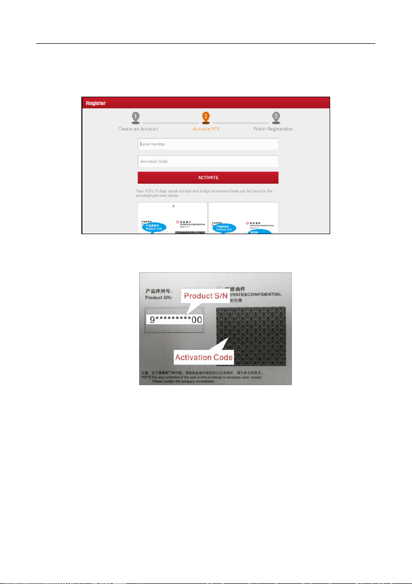
LAUNCH
12
Fill in the information in each field (Items with * must be filled). After inputting,
tap
Register
, the following screen will appear:
Input the 12-digit Product Serial Number and 8-digit Activation Code (can be
obtained from the password envelope), and then tap
Activate
.
Tap
OK
to navigate to the update center to update all available software.
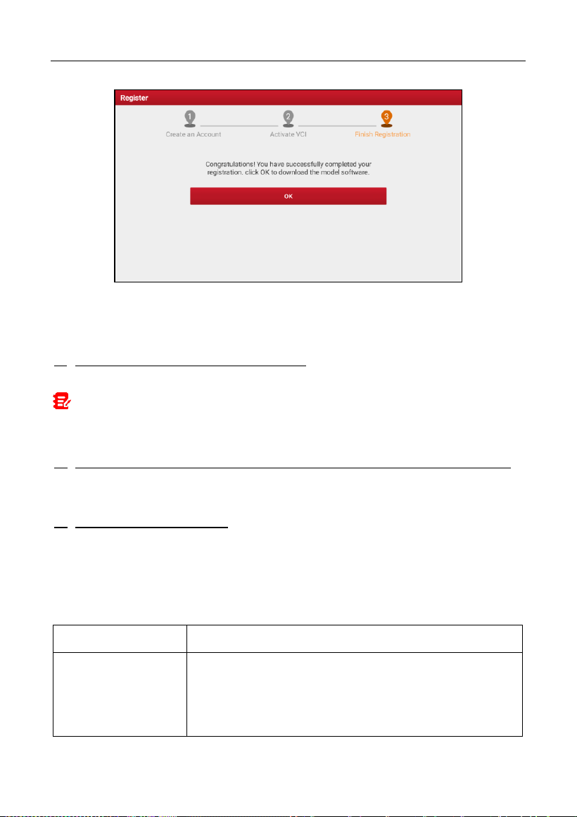
LAUNCH
13
After the registration is successfully complete, the wireless communication
between the tablet and the VCI device is automatically established and user has
no need to configure it again.
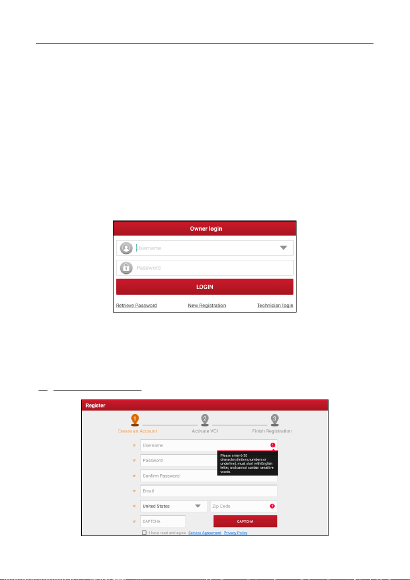
B. If you have registered to be a member, input your name and password, and
then tap
LOGIN
to enter the main menu screen directly.
Note: The tablet has an auto-save function. Once the username and password are
correctly entered, the system will automatically store it. Next time you login the system,
you will not be asked to input the account manually.
C. If you have created a sub-account or bound an existing account to the tool,
tap
Technician login
to login. For more details on sub-accounts, refer to
Chapter 9.11.8.
D. If you forgot the password, tap
Retrieve password
and then follow
on-screen instructions to set a new password.
3.2 Job Menu
It mainly includes the following items:
Name
Description
Intelligent
Diagnose
• Obtain vehicle data from the cloud server to perform
quick test via reading VIN, to avoid various defects
resulting from step-by-step menu selection.
•
Check the historical repair records online.

LAUNCH
14
Local Diagnose
Diagnose a vehicle manually.
Service Function
Perform commonly used repair & maintenance
services.
Remote Diagnose
This option aims to help repair shops or technicians
launch instant messages and remote diagnosis, making
the repair job getting fixed faster.
TPMS
Configures this tool as a professional TPMS (Tire
Pressure Monitoring System) service tool. It needs to
work with the TSGUN device (sold separately) to
perform all kinds of various TPMS functions.
Software Update
Update vehicle diagnostic software and APK.
Diagnostic History
• Access the diagnostic reports from the previously
tested vehicles.
• Resume the previous operation without starting from
scratch.
Feedback
Feedback the recent 20 diagnostic logs for issue
analysis.
ADAS
Perform ADAS (Advanced Driver Assistance System)
calibration operations. It needs to work with the specific
ADAS calibration tool (sold separately).
Mall
Subscribe some extra software or service functions that
are not included in the diagnostic tool online.
Vehicle Coverage
View all the vehicle models that the tool covers.
Info Center
Includes tool information (product user manual and
FAQ), general information (training videos, product
catalogue and newsletter etc) and repair information
(abundant maintenance data are available).
User Info
To manage VCI, reports, change password, configure
wireless Wi-Fi printer, configure system settings and
logout etc.

LAUNCH
15
Other Modules
Includes some add-on modules (such as Videoscope
and BST360 etc), product manual and FAQ etc.
LAUNCH
16
4 Connections
4.1 Preparation
The ignition is turned on.
The vehicle battery voltage range is 11-14 volts.
The throttle is in the closed position.
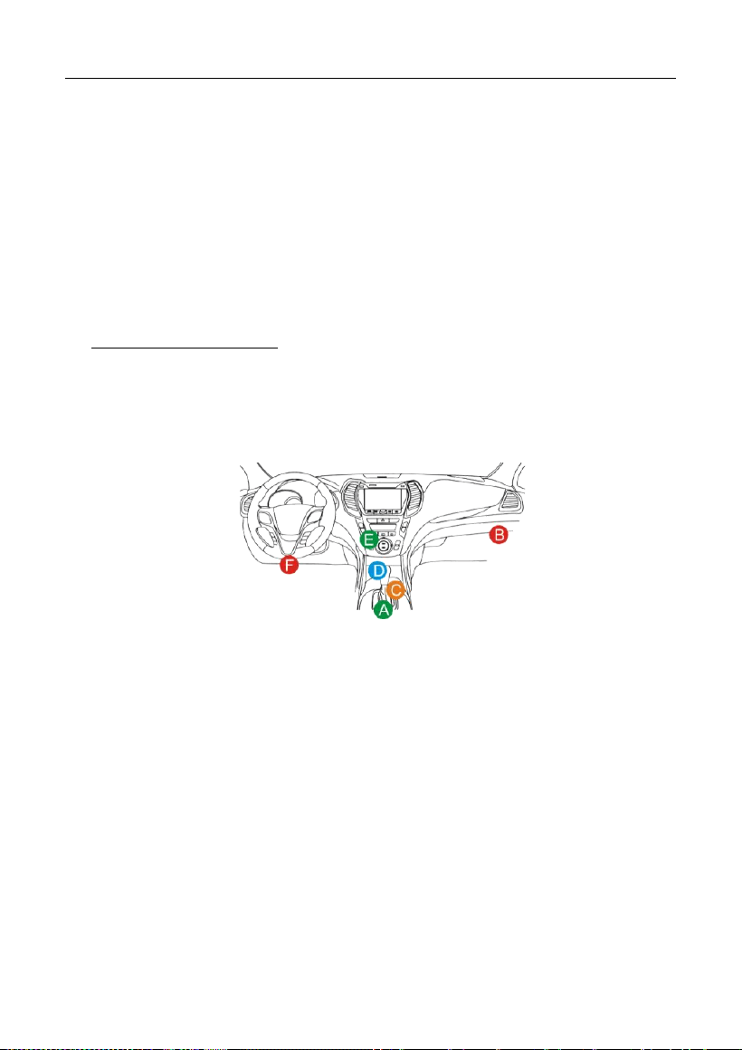
Find DLC location.
For Passenger Vehicles,
The DLC(Data Link Connector) is usually located 12 inches from the center of the
instrument panel, under or around the driver’s side for most vehicles. For some
vehicles with special designs, the DLC location may vary. Refer to the following
figure for location.
A. Opel, Volkswagen, Audi
B. Honda
C. Volkswagen
D. Opel, Volkswagen, Citroen
E. Changan
F. Hyundai, Daewoo, Kia, Honda, Toyota, Nissan, Mitsubishi, Renault, Opel, BMW,
Mercedes-Benz, Mazda, Volkswagen, Audi, GM, Chrysler, Peugeot, Regal, Beijing
Jeep, Citroen and other most popular models
If the DLC cannot be found, refer to the vehicle’s service manual for the location.
4.2 Vehicle Connection
The method used to connect the VCI device to a vehicle’s DLC depends on the
LAUNCH
17
vehicle’s configuration as follows:
A vehicle equipped with an OBD II management system supplies both
communication and 12V power through a standardized DLC.
A vehicle not equipped with an OBD II management system supplies
communication through a DLC connection, and in some cases supplies 12V
power through the cigarette lighter receptacle or a connection to the vehicle
battery.
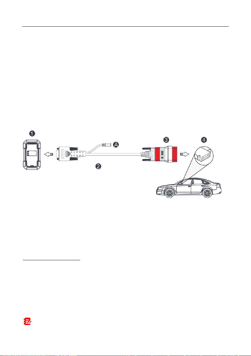
4.2.1 OBD II vehicle Connection
Use the included diagnostic cable (HDB15F to HD15F diagnostic cable + HD15F
to OBD II adaptor) to connect the VCI to the vehicle’s DLC port.
1. VCI
2. HDB15F to HD15F data cable
3. HD15F to OBD II adaptor
4. Vehicle’s DLC port
4.2.2 Non-OBD II vehicle Connection
For non-OBDII vehicle, refer to the above figure to make connection.
1. Select the appropriate adaptor from the non-16pin adaptor kit (sold
separately) according to the vehicle’s DLC port type (4).
2. Loosen the captive screws of the HDB15F to HD15F data cable (2) and
disconnect the HD15F to OBD II adaptor (3) from the data cable.
3. Connect the data cable (2) with the target adaptor on the above figure and
tighten the screws. Other steps shall also apply.
Note: If the pin of the DLC is damaged or the DLC has insufficient power, you can

LAUNCH
18
get power via either of the following methods:
A. Battery Clamps Cable (not included):
Connect one end of the battery clamps cable to the power jack (A) of the diagnostic
cable, and the other end to the vehicle’s battery.
B. Cigarette Lighter Cable (not included):
Connect one end of the cigarette lighter cable to the power jack (A) of the diagnostic
cable, and the other end to the cigarette lighter receptacle.
If you choose to perform vehicle diagnosis via data cable, connect one end of
the data cable into the VCI, and the other end into the USB port of the tablet.
LAUNCH
19
5 Diagnosis
5.1 Intelligent Diagnose
Through simple Bluetooth communication between the display tablet and VCI,
you can easily get the VIN (Vehicle Identification Number) information of the
currently identified vehicle. Once the VIN is successfully identified, the system
will retrieve it from the remote server and then guide you to vehicle information
page without the necessity of step-by-step manual menu selection.
The vehicle information page lists all historical diagnostic records of the vehicle,
which lets the technician have a total command of the vehicle faults. In addition,
a quick dial to local diagnose and diagnostic function are also available on this
page for reducing the roundabout time and increasing productivity.
Notes:
• Before using this function, please make sure the VCI is properly connected to the
vehicle’s DLC. For detailed connection, see Chapter 4.2 “Vehicle Connection”.
• A stable network connection is required for this function.
1. Tap
Intelligent Diagnose
on the Job menu screen to start pairing with the
VCI.
2. After pairing is complete, the tablet starts reading the vehicle VIN.
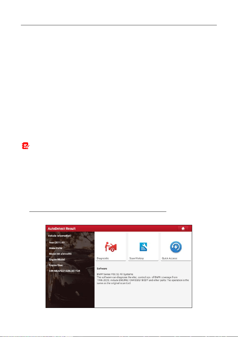
A. If the VIN can be found from the remote server database, the following
screen will appear:
LAUNCH
20
• Tap “Diagnostic” to start a new diagnostic session.
• Tap “Scan History” to view its historical repair record. If there are records
available, it will be listed on the screen in sequence of date. If no records
exist, the screen will show “No Record”.
• Tap “View record” to view the details of the current diagnostic report.
• To perform other functions, tap “Quick access” to directly go to the function
selection screen. Choose the desired one to start a new diagnostic
session.
B. If the tablet failed to access the VIN information, the following screen will
appear:
• Tap the input field to directly, tap
OK
. If the VIN exists on the remote server,
the system will enter the diagnostic function selection screen.
• Tap to launch the VIN recognition module.

LAUNCH
21
Place the VIN inside the viewfinder rectangle to scan it. The most recognizable
location for this number is in the top left corner on the vehicle’s dashboard. Other
locations include the driver’s door or post, and the firewall under the hood.
• Tap to switch the display mode of the screen.
• Tap to turn the camera flash on.
• Tap to choose it from the record list if the VIN of the vehicle has been
scanned before.
• Tap to input the VIN manually if the tablet has failed to identify the VIN
of the vehicle.
• Tap to scan the VIN barcode. If the VIN barcode cannot be recognized,
please manually input the VIN.
• Tap to scan the VIN character. If the VIN character cannot be
recognized, please manually input the VIN.
After scanning, the screen will automatically display the result.
LAUNCH
22
• If the VIN scanned is incorrect, tap the result field to modify it and then tap
OK
.
• To scan it again, tap
REPEAT
.
If the VIN exists on the remote server, the system will enter the diagnostic
function selection screen.
5.2 Local Diagnose
In this mode, you need to execute the menu-driven command and then follow
the on-screen instruction to proceed.
Tap
Local Diagnose
to enter the vehicle selection page.
2 approaches are provided for you to access the vehicle diagnostic software.
Choose any one of the following ways:
1. VIN SCAN enables you to access it more quickly.
Tap
VIN Scan
, the following screen will appear:
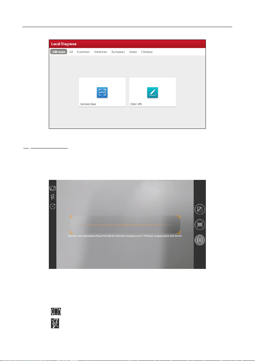
LAUNCH
23
In this case, camera scan and enter VIN are available.
A. Camera Scan: In this mode, the VCI should be connected to the vehicle’s
DLC first, and then a Bluetooth communication should be established
between the tablet and the VCI.
Tap
Camera Scan
, a screen similar to the following will appear:
Place the VIN inside the viewfinder rectangle to scan it. The most
recognizable location for this number is in the top left corner on the vehicle’s
dashboard. Other locations include the driver’s door or post, and the firewall
under the hood.
• Tap to switch the display mode of the screen.
• Tap to turn the camera flash on.
LAUNCH
24
• Tap to choose it from the record list if the VIN of the vehicle has been
scanned before.
• Tap to input the VIN manually if the tablet has failed to identify the
VIN of the vehicle.
• Tap to scan the VIN barcode. If the VIN barcode cannot be
recognized, please manually input the VIN.
• Tap to scan the VIN character. If the VIN character cannot be
recognized, please manually input the VIN.
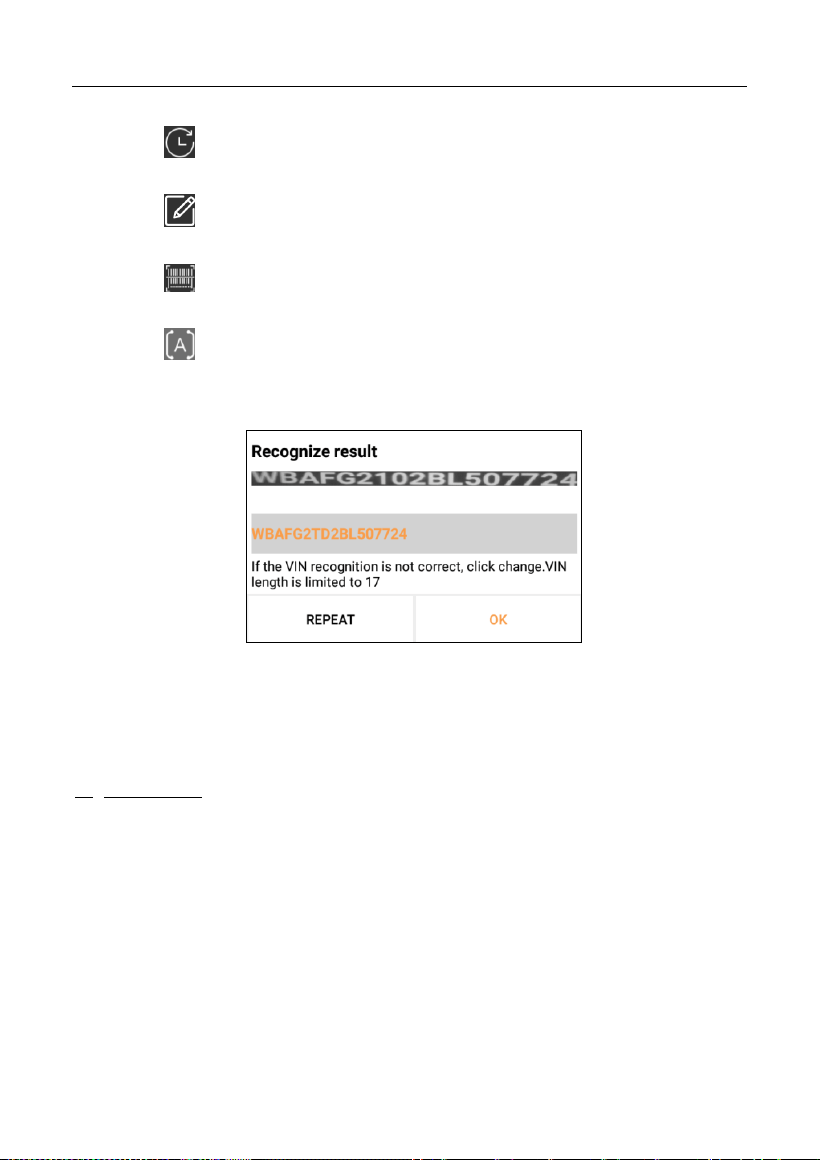
After scanning, the following screen will appear.
If the VIN scanned is incorrect, tap the result field to modify it and then tap
OK
.
If the VIN exists on the remote server, the system will navigate to the
diagnostic function selection screen directly.
Tap the desired option to perform the corresponding diagnostic function.
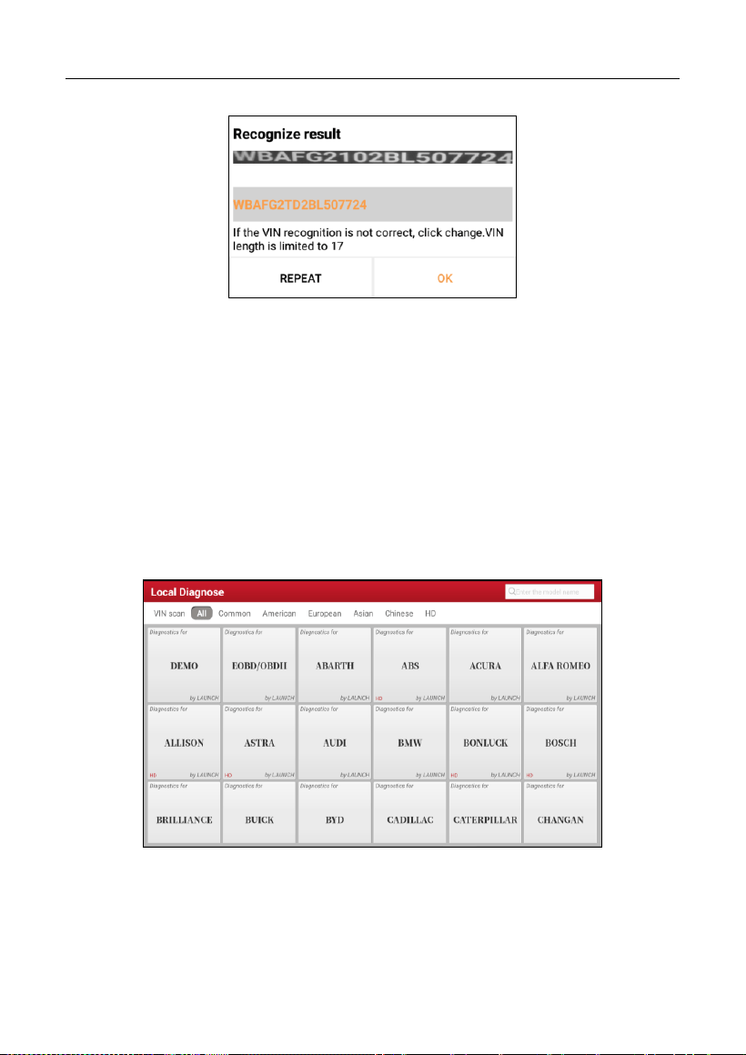
B. INPUT VIN: In this mode, you can input the vehicle VIN manually.
Tap
Enter VIN
, the following screen will appear.
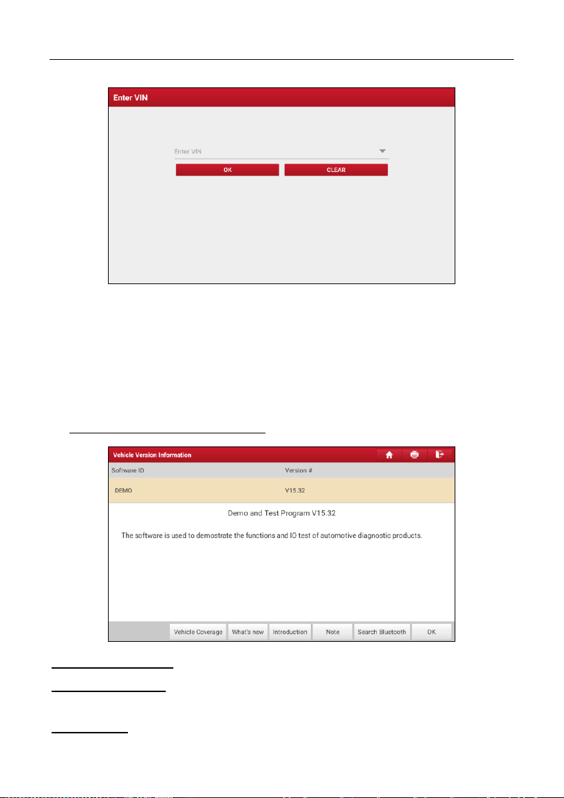
LAUNCH
25
Input the VIN, and tap
OK
, the tablet will automatically identify the vehicle
model and directly navigate to the diagnostic function selection menu.
2. Tap a corresponding diagnostic software logo, and then follow the on-screen
instruction to access the diagnostic software.
Take Demo (Version 15.32) as an example to demonstrate how to diagnose a
vehicle.
1). Select diagnostic software version: Tap the
DEMO
to go to Step 2.
On-screen Buttons:
Vehicle Coverage:
Tap to view the vehicle models that the current diagnostic
software covers.
What’s new:
Tap to view the optimized items and enhancements.
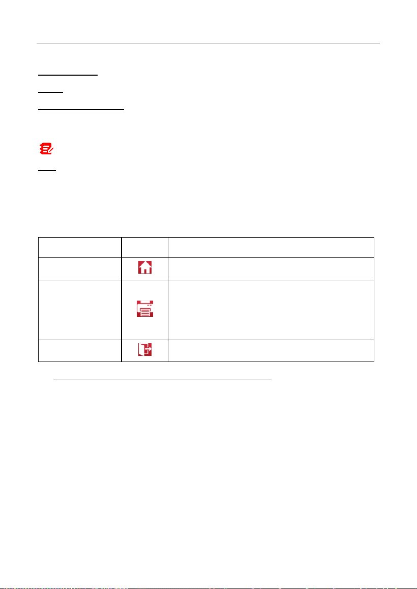
LAUNCH
26
Introduction:
Tap to check the software function list.
Note:
Tap to read some precautions on using the current diagnostic software.
Search Bluetooth:
Tap to search for the available VCI. After the VCI is
successfully activated, it will be bound to the user account and paired with the
tablet automatically.
Note: No Bluetooth connection is required for DEMO program.
OK:
Tap it to go to next step.
The diagnostics toolbar contains a number of buttons that allow you to print the
displayed data or make other controls. It is displayed on the upper right corner of
the screen and goes through the whole diagnostic session. The table below
provides a brief description for the operations of the diagnostics toolbar buttons:
Name
Button
Description
Home
Returns to Job menu screen.
Print
Tap to print the current screen. Before printing,
you need to configure the wireless printer
following the steps described in Chapter
9.11.3.
Exit
Exits the diagnostic application.
2). Select vehicle model (varies with different versions): Select the desired
vehicle model. Here we take
Ford
for example to demonstrate how to
diagnose a vehicle.
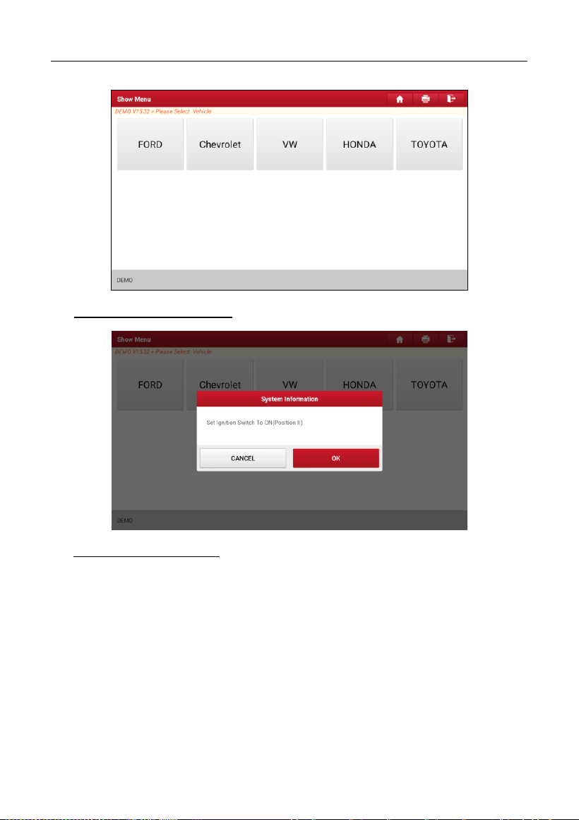
LAUNCH
27
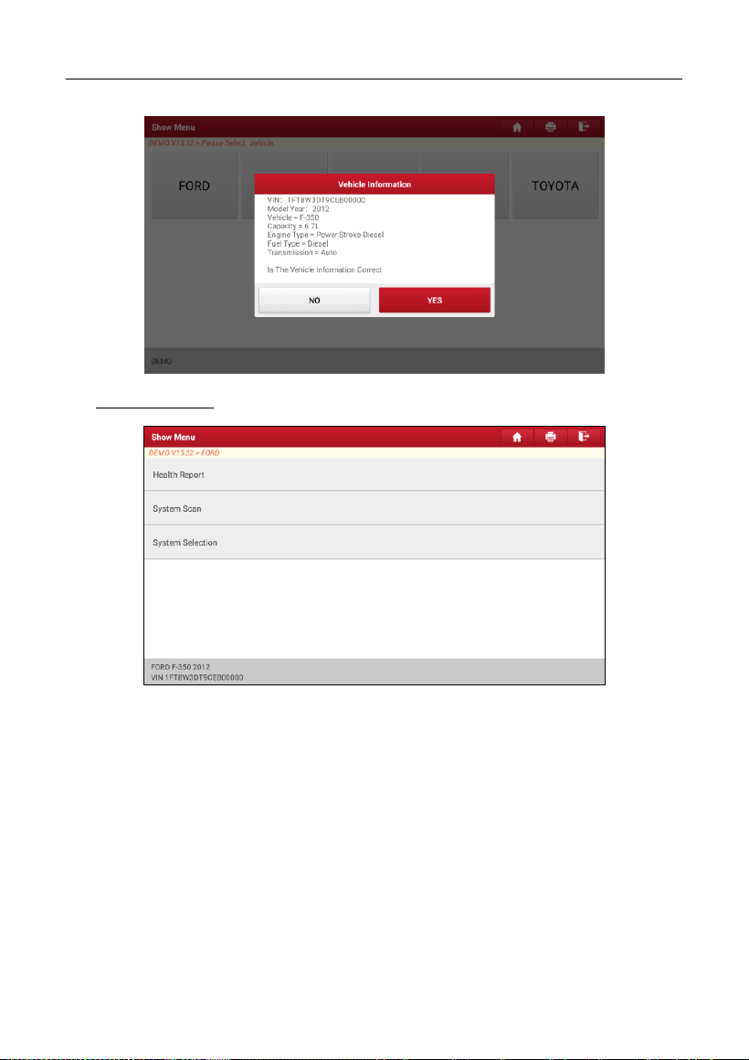
3). Turn the ignition key to ON: Set the ignition switch to on.
4). Read vehicle information: After reading the vehicle information, double check
if the vehicle information is correct or not. If yes, tap
Yes
to continue.
LAUNCH
28
5). Select test item: Select the desired test item to proceed.
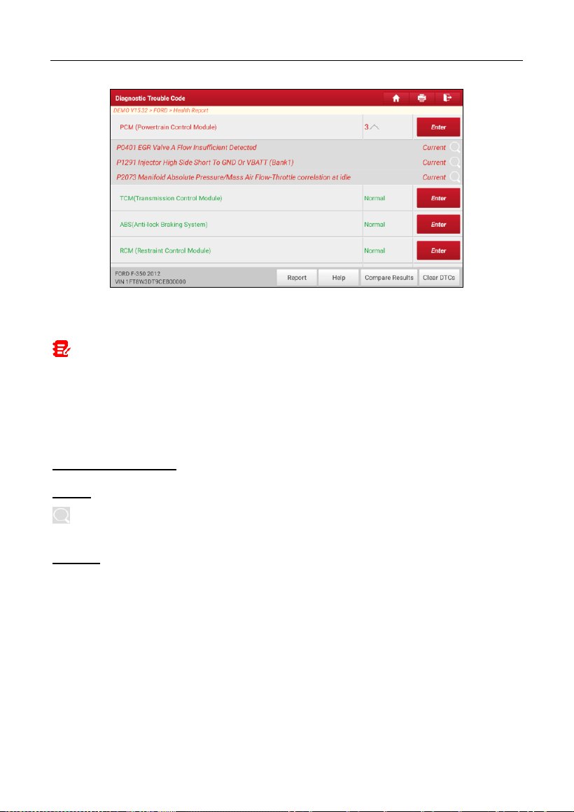
5.2.1 Health Report (Quick Test)
This function varies from vehicle to vehicle. It enables you to quickly access all
the electronic control units of the vehicle and generate a detailed report about
vehicle health.
On the test item selection screen, tap
Health Report
and turn on the ignition
switch, the system will start scanning the ECUs. Once the scanning process is
complete, the following screen will appear:
LAUNCH
29
The tested system with fault code appears in red and the system functioning
properly displays in black (normally).
Note: Diagnostic Trouble Codes or Fault Codes can be used to identify which
engine systems or components that are malfunctioning. Never replace a part based only
on the DTC definition. Retrieving and using DTCs for troubleshooting vehicle
operation is only one part of an overall diagnostic strategy. Follow testing procedures
(in vehicle’s service manual), instructions and flowcharts to confirm the locations of the
problem.
On-screen Buttons:
Enter:
Tap to enter the diagnostic function selection screen.
(Search):
Highlight certain diagnostic trouble code and tap it to retrieve it in
the search engine.
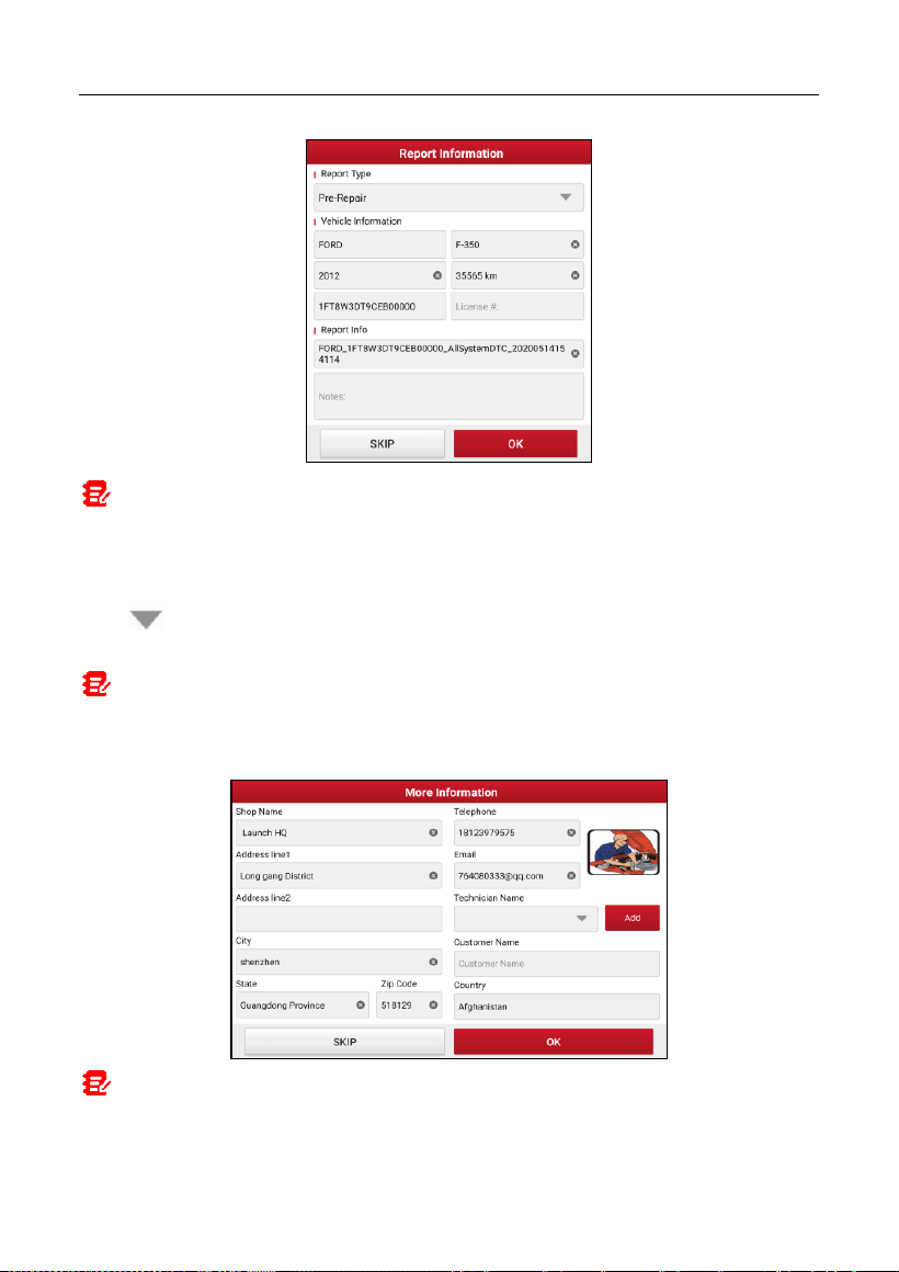
Report:
Tap to save the diagnostic result as a health report.
LAUNCH
30
Note: Diagnostic report is classified into three categories: Pre-Repair report,
Post-Repair report and Diagnostic Scan. No matter which type you saved the report as,
the report type will be appended as a tag on the upper right corner of the diagnostic
report for easier identification.
Tap to select the report type from the option list and input the required
information, and then tap
OK
.
Note: To facilitate the comparison of the pre-repair and post-repair reports and get
accurate test result, please make sure you saved the right type of the diagnostic report.
To save the report as a common diagnostic report, select
Diagnostic Scan
.
Note: For workshop information, tap the input box to enter it. Alternatively you can
also set it in
User Info -> Settings -> Shop Information
.
Once you configured the information, it will be automatically generated every time you
LAUNCH
31
saved the diagnostic report. All vehicle and workshop information will be appended as
tags on the diagnostic report.
To ignore the workshop information, tap
Skip
to go to the report details screen.
On the report details screen, tap
Save
to save it. All diagnostic reports are saved
in
User Info -> My Report -> Health Reports
.
Help:
Tap to view the help information of the selected DTC item.
Compare Results:
Tap to select the pre-repair report to compare. By
comparison of the pre- and post- repair reports, you can easily identify which
DTCs are cleared and which remain unfixed.
•
Post
indicates DTC status of post-repair.
•
Pre
indicates DTC status of pre-repair.
LAUNCH
32
Note: Before performing this function, please make sure that:
• You have saved a pre-repair report of the currently tested vehicle, and
• You have already made some repairs and service and cleared the DTCs after the
pre-repair reported is generated. Otherwise, no differences exist between the pre-
and post- repair reports.
Clear DTCs:
Tap to clear the existing diagnostic trouble codes.
Note: Clearing DTCs does not fix the problem(s) that caused the code(s) to be set.
If proper repairs to correct the problem that caused the code(s) to be set are not made,
the code(s) will appear again and the check engine light will illuminate as soon as the
problem that cause the DTC to set manifests itself.
5.2.2 System Scan
This option allows you to quickly scan which systems are installed on the
vehicle.
On the test item selection screen, tap
System Scan
, the system start scanning
the systems. Once the scanning process is complete, the following screen will
appear.
Tap the desired system to go to the diagnostic function selection screen. For
detailed operations on diagnostic function, please refer to Chapter 5.2.3.
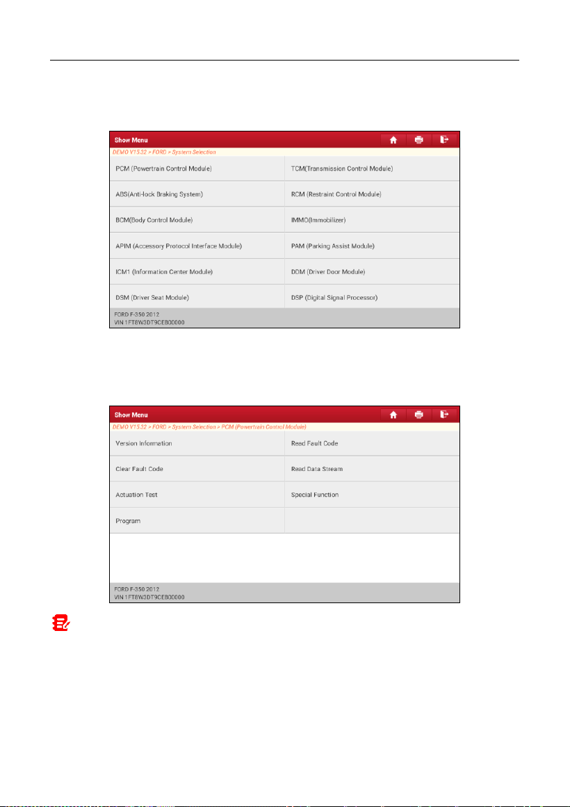
5.2.3 System Selection
This option allows you to manually select the test system and function step by
step.
LAUNCH
33
On the test item selection screen, tap
System Selection
, the screen displays as
follows:
Swipe the screen from the bottom to view the vehicle system on the next page.
Tap the target system (take
ECM
for example) to navigate to the diagnostic
function selection screen.
Note: Different vehicle has different diagnostic menus.
A. Version Information
This function is used to read the version information of system mode, vehicle
VIN, software and ECU.
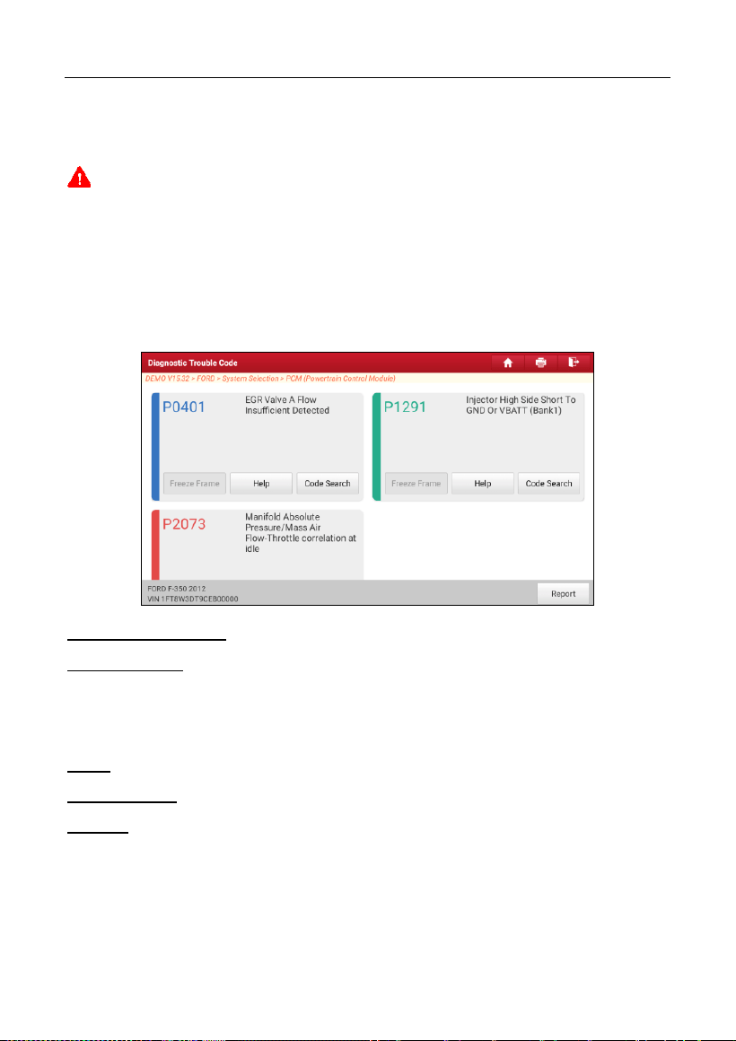
B. Read Fault Code
LAUNCH
34
This function displays the detailed information of DTC records retrieved from the
vehicle’s control system.
Caution: Retrieving and using DTCs for troubleshooting vehicle operation is only
one part of an overall diagnostic strategy. Never replace a part based only on the DTC
definition. Each DTC has a set of testing procedures, instructions and flow charts that
must be followed to confirm the location of the problem. This information can be found
in the vehicle’s service manual.
On the diagnostic function selection screen, tap
Read Fault Code
, the screen
will display the diagnostic result.
On-screen Buttons:
Freeze Frame:
When an emission-related fault occurs, certain vehicle
conditions are recorded by the on-board computer. This information is referred
to as freeze frame data. Freeze frame data includes a snapshot of critical
parameter values at the time the DTC is set.
Help:
Tap to view the help information.
Code Search:
Tap to search for more information about the current DTC online.
Report:
Tap to save the current data in text format. All reports are saved in
User
Info -> My Report -> Health Reports
.
C. Clear Fault Code
This function enables you to erase the codes from the vehicle after reading the
retrieved codes from the vehicle and certain repairs have been carried out.
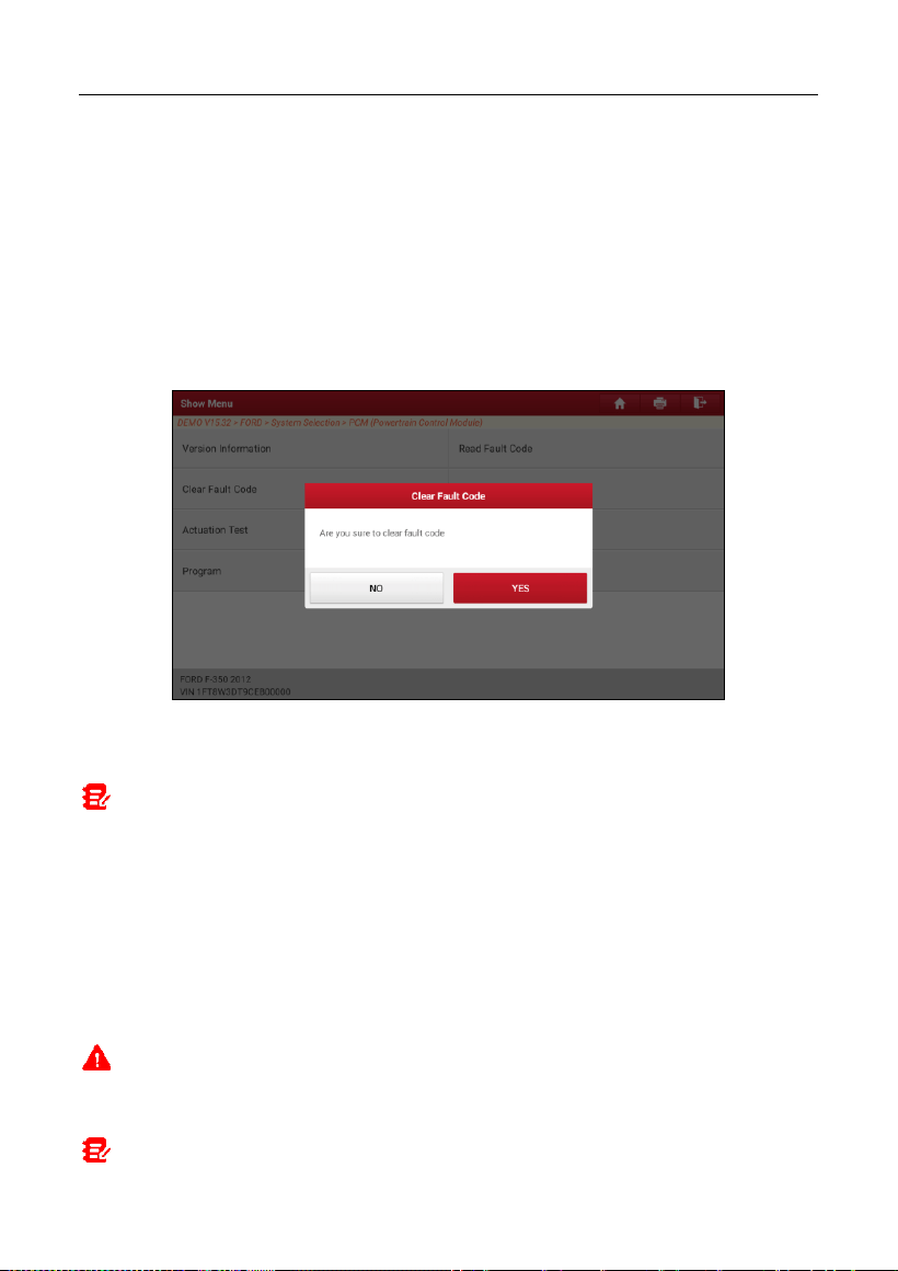
LAUNCH
35
Before performing this function, make sure the vehicle’s ignition key is in the ON
position with the engine off.
Clearing DTCs does not fix the problem(s) that caused the code(s) to be set. If
proper repairs to correct the problem that caused the code(s) to be set are not
made, the code(s) will appear again and the check engine light will illuminate as
soon as the problem that cause the DTC to set manifests itself.
On the diagnostic function selection screen, tap
Clear Fault Code
, the following
screen will appear.
Tap
YES
, the system will automatically delete the currently existing trouble
code.
Note: After clearing, you should retrieve trouble codes once more or turn ignition
on and retrieve codes again. If there are still some trouble codes in the system, please
troubleshoot the code using a factory diagnosis guide, then clear the code and recheck.
D. Read Data Stream
This option lets you view and capture (record) real-time Live Data. This data
including current operating status for parameters and/or sensor information can
provide insight on overall vehicle performance. It can also be used to guide
vehicle repair.
Caution: If you must drive the vehicle in order to perform a troubleshooting
procedure, ALWAYS have a second person help you. Trying to drive and operate the
diagnostic tool at the same time is dangerous, and could cause a serious traffic accident.
Note: The real time (Live Data) vehicle operating information (values/status) that
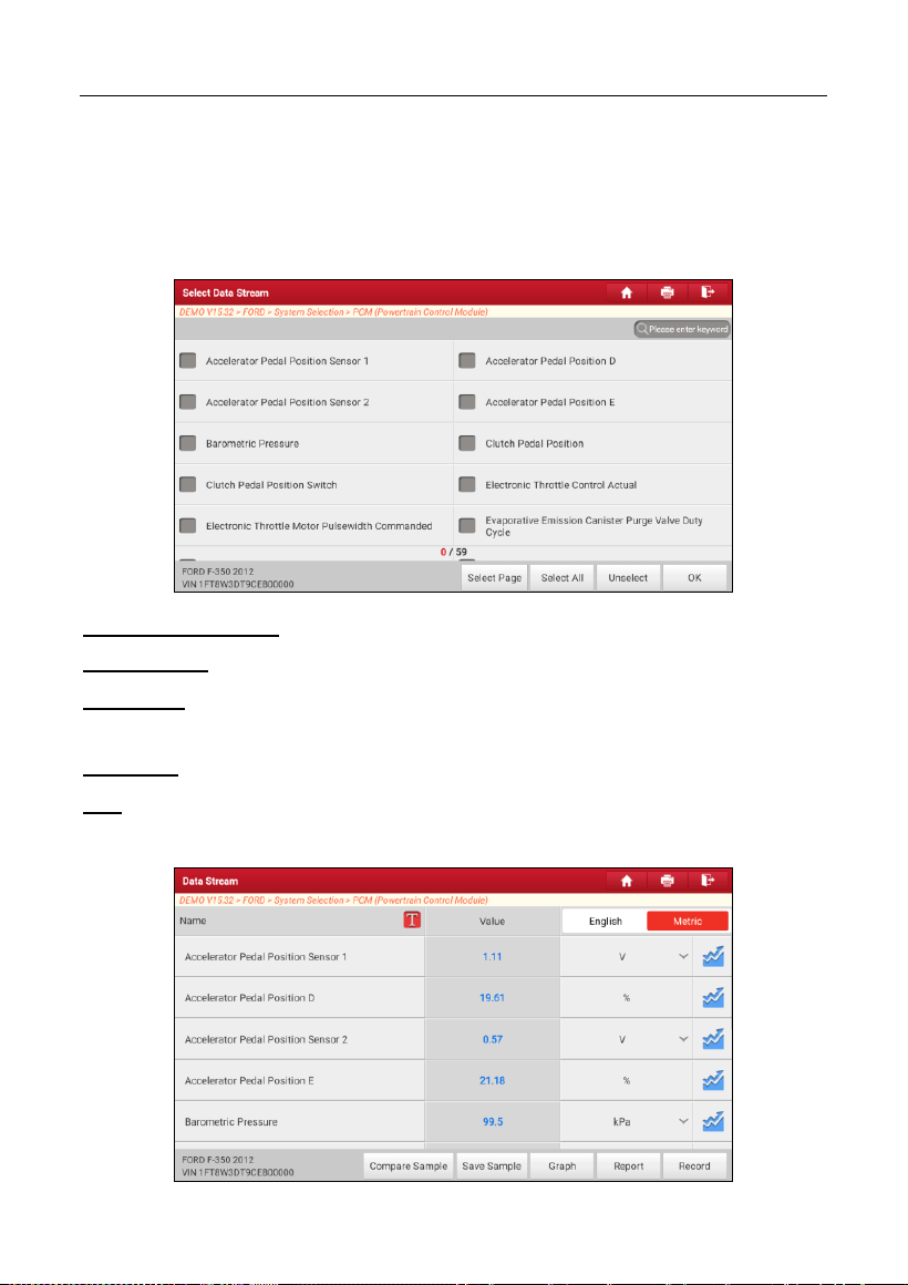
LAUNCH
36
the on-board computer supplies to the tool for each sensor, actuator, switch, etc. is
called Parameter Identification Data (PID).
On the diagnostic function selection screen, tap
Read Data Stream
, the
following screen will appear.
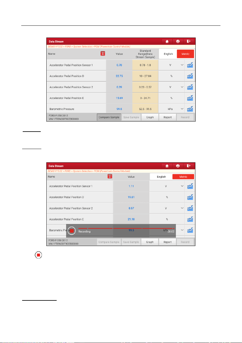
On-screen Buttons:
Select Page:
Tap to select all items of the current page.
Select All:
Tap to select all items. To select certain data stream item, just check
the box before the item name.
Unselect:
Tap to deselect all data stream items.
OK:
Tap to confirm and jump to the next step.
After selecting the desired items, tap
OK
to enter the data stream reading page.
LAUNCH
37
Notes:
1. Tap , the following popup will appear.
Here the user can set different display style for each selected item.
indicates sticky top. If it is tapped, it will change into . On the data stream
display screen, the data stream item with will be shown on the top of the selected
data stream list. To remove it from the top of the list, just tap it again.
B indicates this item will be displayed in
Bold
.
A indicates this item will be displayed in Red.
2. Tap English or Metric to switch the measurement unit.
3. If the value of the data stream item is out of the range of the standard (reference)
value, the whole line will display in red. If it complies with the reference value, it
displays in blue (normal mode).
4. The indicator 1/X shown on the bottom of the screen stands for the current
page/total page number. Swipe the screen from the right/left to advance/return to the
next/previous page.
There are 3 types of display modes available for data viewing, allowing you to
view various types of parameters in the most suitable way.
Value – This is the default mode which displays the parameters in texts and
shows in list format.
Graph – Displays the parameters in waveform graphs.
Combine – This option is mostly used in graph merge status for data
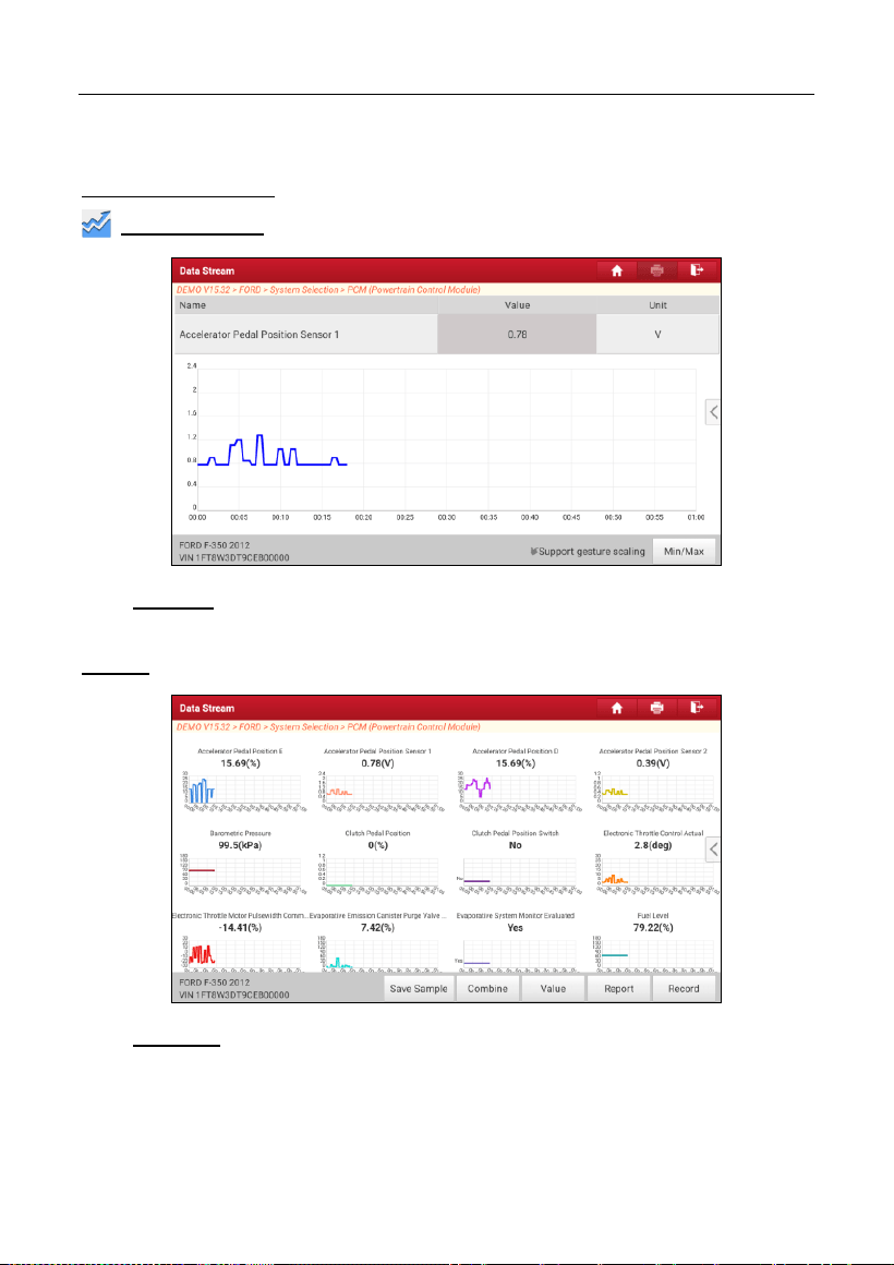
LAUNCH
38
comparison. In this case, different items are marked in different colors.
On-screen Buttons:
Graph(Single):
Tap to view the parameter in waveform graph.
•
Min/Max
: Tap to define the maximum / minimum value. Once the value
goes beyond the specified value, the system will alarm.
Graph:
Tap to view the parameters in waveform graphs.
•
Combine
: This option is mostly used in graph merge status for data
comparison. In this case, different items are marked in different colors
(maximum 4 items can be displayed on the same screen simultaneously).
If the graph is more than one page, swipe the screen from the left to jump
to the next page.
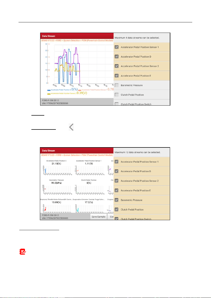
LAUNCH
39
•
Value
: Switches the current graph display mode to the Value display
mode.
•
Customize
: Tap , a pull-down list of the data stream items appears on
the screen. Select / deselect the desired items, and then screen will
display / remove the waveforms corresponding to these items immediately.
Compare Sample
: Tap to select the sample DS file.
All the values you customized and saved in process of DS sampling will be
imported into the
Standard Range
(See below) column for your comparison.
Note: Before executing this function, you have to sample the values of data stream
items and save it as a sample Data Stream file.
LAUNCH
40
Report
: Tap to save the current data in text format. All reports are saved in
User
Info -> My Report -> Health Reports
.
Record
: Tap to start recording diagnostic data. Recorded live data can serve as
valuable information to help you in troubleshooting of vehicle problems.
Tap to end recording and save it. The saved file follows the naming rule: It
begins with vehicle type, and then the product S/N and ends with record starting
time (To differentiate between files, please configure the accurate system time).
All diagnostic records can be replayed from
User Info -> My Report ->
Recorded Data
.
Save Sample
: This item enables you to customize the standard range of live
data stream items and save it as DS sample file. Each time you run the data
stream items, you can call out the corresponding sample data to overwrite the
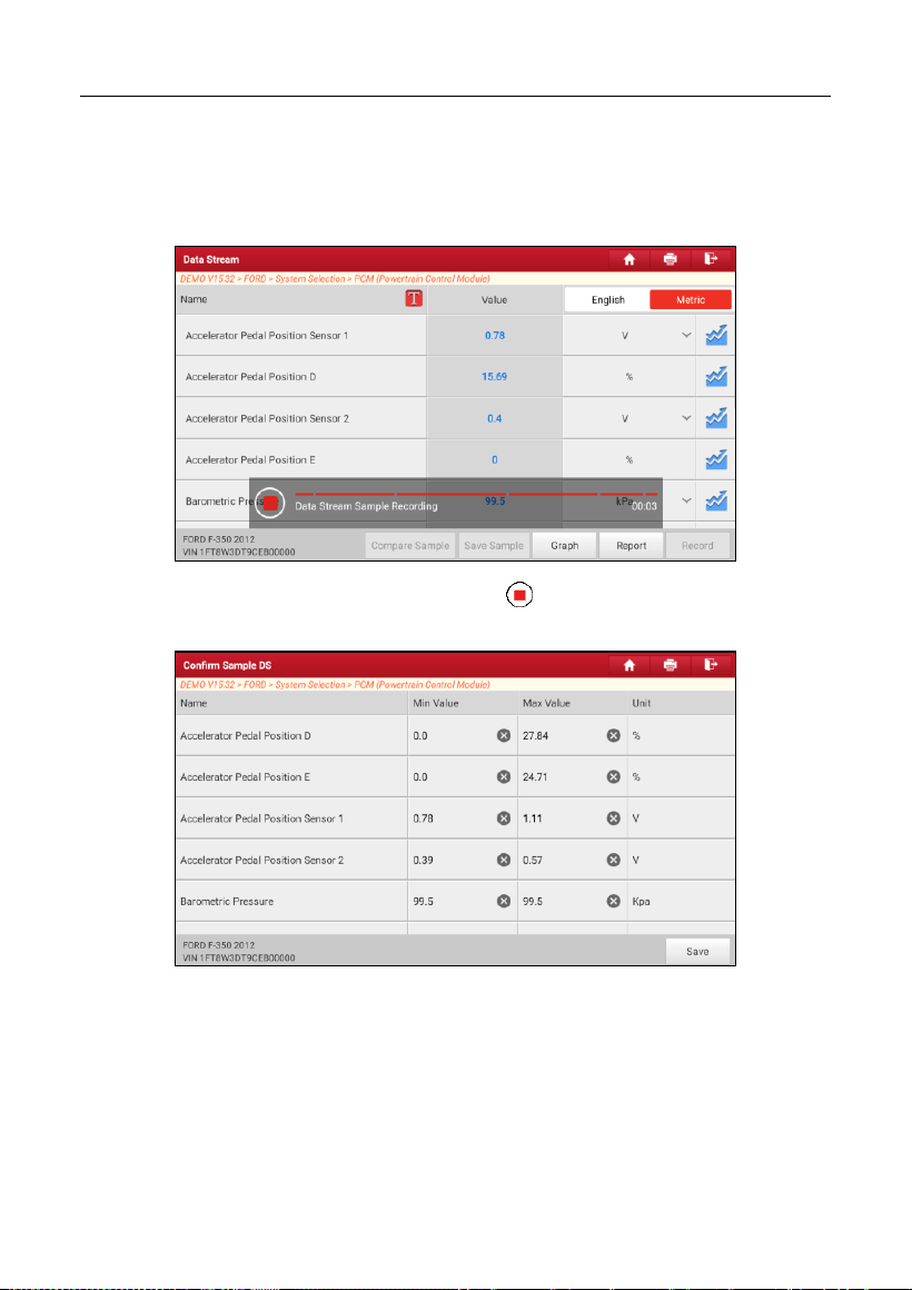
LAUNCH
41
current standard range.
Tap it to start recording the sample data (*Note: Only data stream items with
measurement units will be recorded), the following screen will appear:
Once the recording process is complete, tap to stop it and navigate to the
data revision screen.
Tap the Min./Max. value to change it. After modifying all desired items, tap
Save
to save it as a sample DS file. All DS files are stored in
User Info -> Sample
.
E. Actuation Test
This option is used to access vehicle-specific subsystem and component tests.
Available test vary by vehicle manufacturer, year, and model.
During the actuation test, the display tablet outputs commands to the ECU in
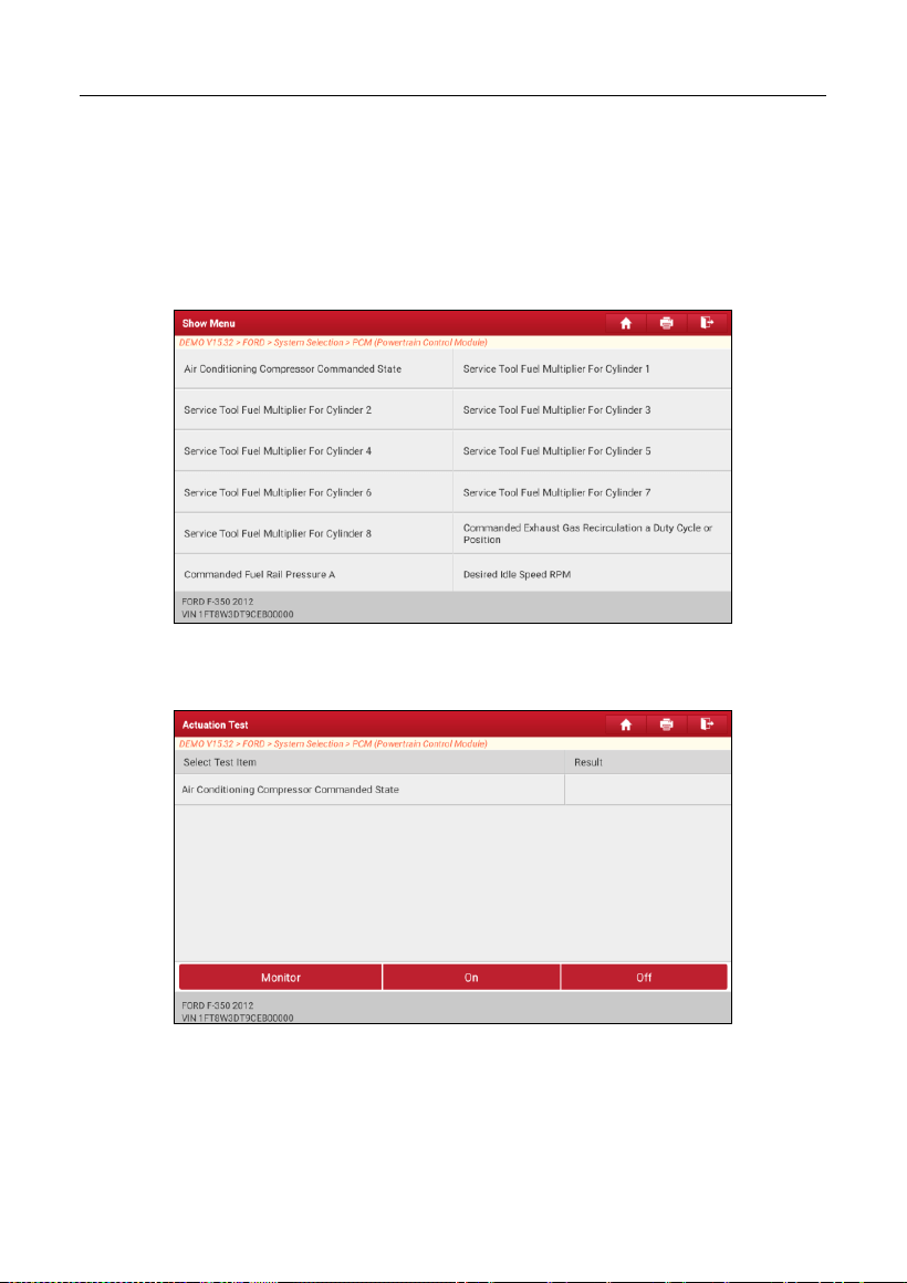
LAUNCH
42
order to drive the actuators, and then determines the integrity of the system or
parts by reading the ECU data, or by monitoring the operation of the actuators,
such as switching an injector between two operating states.
On the diagnostic function selection screen, tap
Actuation Test
, the following
screen will appear:
Simply follow the on-screen instructions and make appropriate selections to
complete the test.
Each time when an operation is successfully executed, Completed displays.
LAUNCH
43
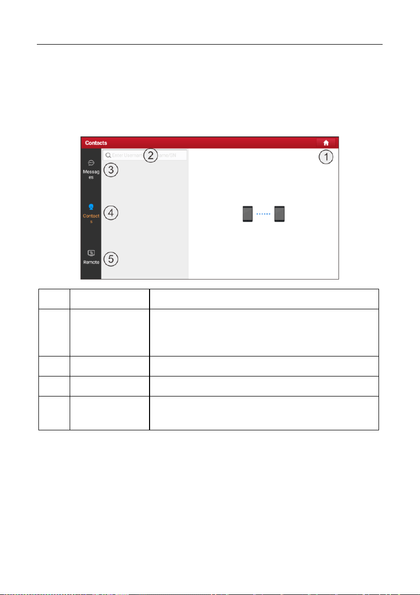
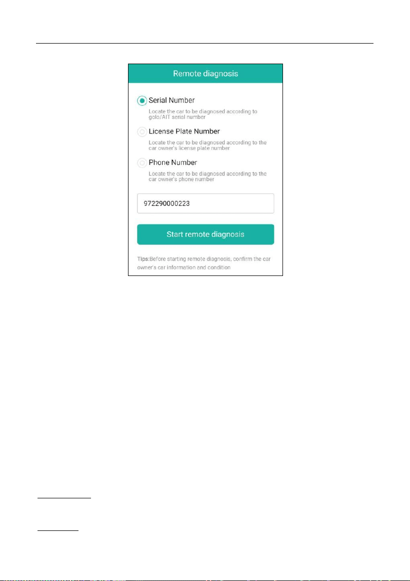
5.3 Remote Diagnose
This module helps repair shops or mechanics to diagnose a remote vehicle, and
launch instant messages, allowing for improved efficiency and faster repairs.
Tap
Remote Diagnose
on the Job menu, the screen appears blank by default.
1
Home Button
Navigate to the Job menu screen.
2
Search Bar
Directly input the username of the tool for searching,
and then tap the desired one to add it into Contacts
list.
3
Messages Tab
A red dot will appear indicating a received message.
4
Contacts Tab
Enter the friend list.
5
Remote Switch
Your technician can control your tool remotely once
the switch is ON.
5.3.1 Add Friends
Tap
Contacts
. By default it appears blank.
In the search bar, input the partner’s username and tap
Search
to start
searching.
The partner must be the users who have registered specific diagnostic tools.
They may be the following:
Workshop
LAUNCH
44
Technician
golo users
Once the result matches the keyword, the following screen will appear:
Here you can tap
Remote Diagnose
to launch remote diagnostics directly or
choose to add the partner into the Contacts list.
Tap the desired name from the list, the following screen will appear:
Tap
Add friend
to send your request.
Once the partner receives the request, a beep will sound. Tap
Messages
:
• Once the partner agreed your request, he/she will automatically be listed in
the Contacts tab.
• If a technician sent you a friend request, tap
Agree
and his/her name will
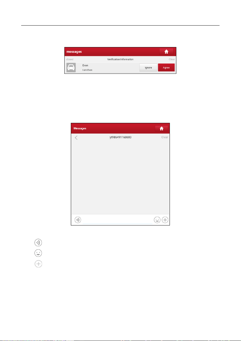
LAUNCH
45
appear in the Contacts list. Or tap
Ignore
to ignore this request.
5.3.2 Start Instant Messaging
The I/M (Instant Messaging) function is open to all users who had the diagnostic
tool equipped with this module.
After adding your friends, tap the desired one’s photo to enter the following
screen:
Tap the input field and use the on-screen keyboard to send the text message.
Tap
to send the voice message.
Tap
to send the emoj.
Tap
to call out more function options.
LAUNCH
46
File: Choose diagnostic reports or local files to send.
Picture: Choose screenshots or pictures to send.
Remote Diagnose: To start a remote diagnostic session. For details, refer to
Chapter 5.3.4.
Camera: Open camera to take pictures.
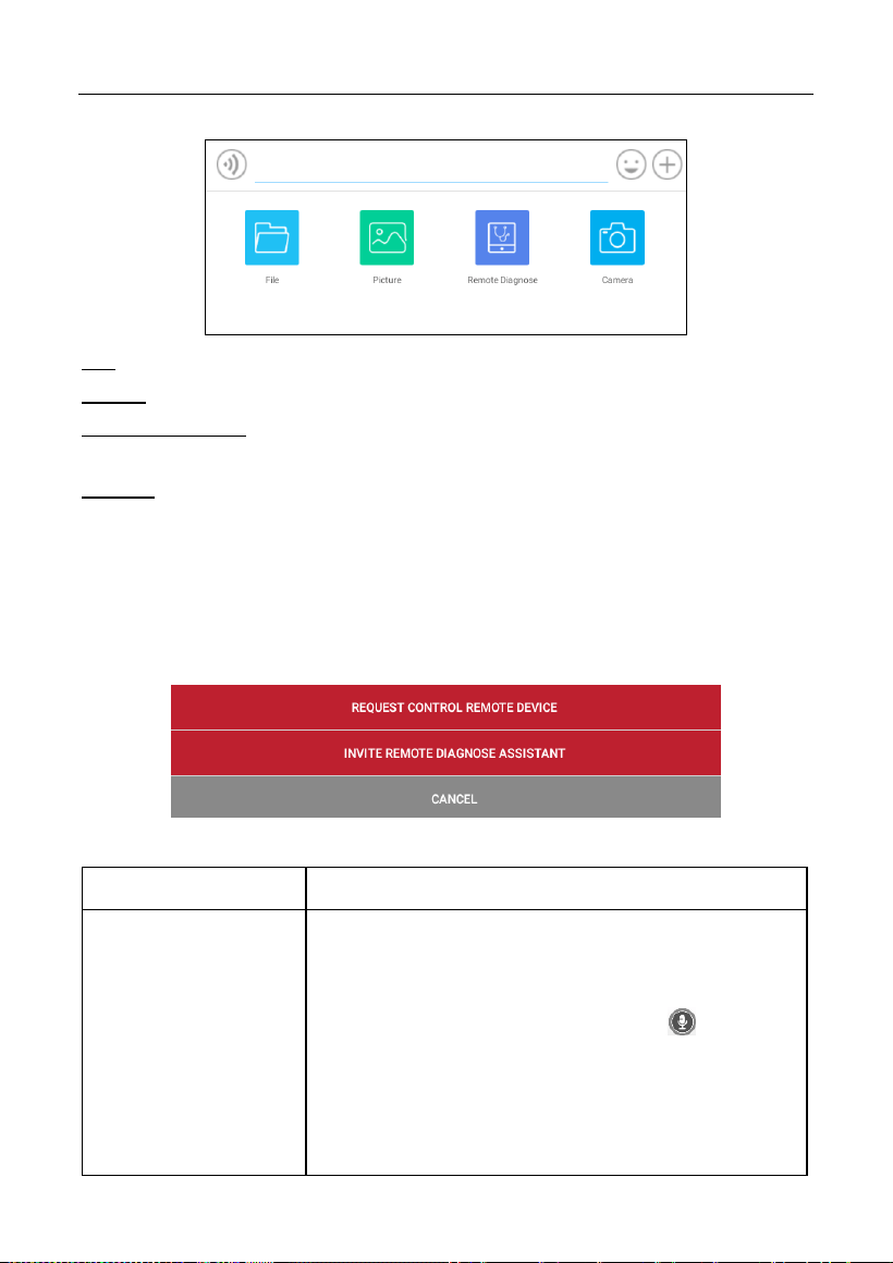
5.3.3 Launch Remote Diagnosis (Device-To-Device)
The tool is allowed to initiate remote diagnosis with other diagnostic tools, which
are equipped with this module.
On the function option selection screen, tap
Remote Diagnostic
, the following
pull-down menu will appear:
These options are defined as follows:
Actions
Results
Request control
remote device
Request to control the partner’s device remotely to
help him diagnose the vehicle.
*Notes:
In process of remote diagnosis, tap the button to
send a voice message.
Once vehicle diagnosis is complete, a report will be
created. Input your comments on this report, and then
tap
Send Report
to send it to the partner.
LAUNCH
47
Tap “Request control remote device”
Wait for partner’s confirmation
Start connecting after request confirmed
Start Diagnosis
Generate diagnostic report
Invite remote
diagnostic assistant
Use this option to invite a technician to perform a
remote control on your tool.
Notes:
In process of remote diagnosis, tap the button to
send a voice message.
Once you received the report from the partner, tap
View Report
to view details. All diagnostic reports are
saved under
User Info -> My
Report -> Remote
Report
.
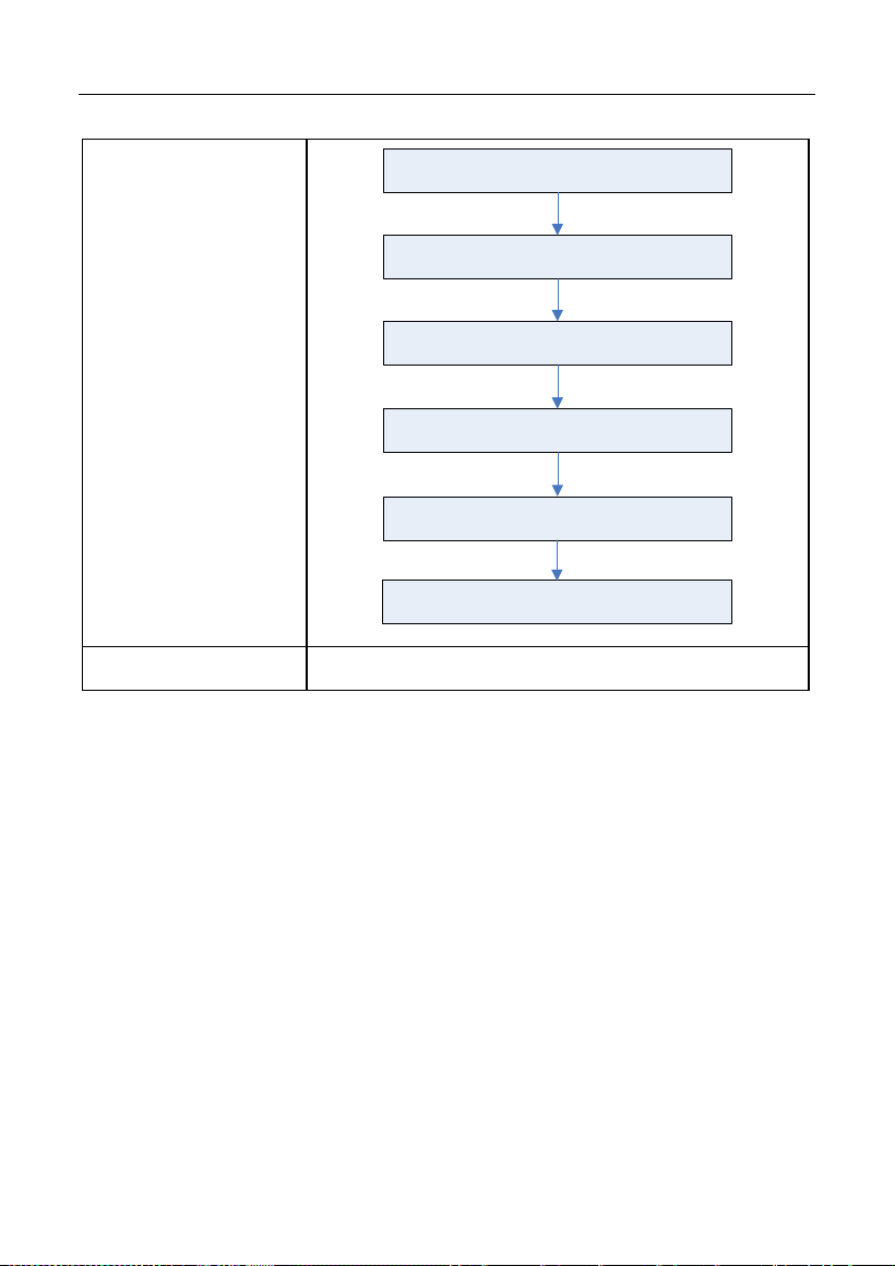
LAUNCH
48
Tap “Invite remote diagnostic assistant”
Choose the desired diagnostic software
Wait for partner’s confirmation
Start connecting after request confirmed
Start Diagnosis
Generate diagnostic report
Cancel
To cancel this operation.
LAUNCH
49
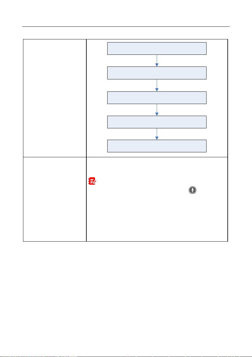
5.3.4 Launch Remote Diagnosis (Device-To-PC)
User also can ask for remote control from a PC client technician.
Slide the switch to ON
Notify the partner of the remote diagnostic web link
Input the partner’s official account and password
Input the Serial Number of your handset
Start Diagnosis
Generate diagnostic report
Tap
Remote
, the following screen will appear:
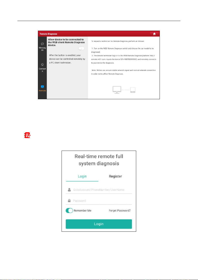
LAUNCH
50
1. Slide the switch to ON so that the partner can find and connect to this device
while using the PC.
2. Notify the partner of the PC client website http://remote.x431.com. When the
partner accesses the link, the PC displays as below:
Note: Before processing remote diagnosis, please make sure the tool is properly
connected to the vehicle.
3. Tell the partner to input his own official technician account and password, and
then tap
Login
to navigate to the following figure.
LAUNCH
51
4. Tell the partner to enter the Serial Number provided by you, and then tap
Start remote diagnosis
to control your device remotely.
In process of remote diagnosis, please note the following things:
1) You are not suggested to execute any actions.
2) The partner is not allowed to save any diagnostic reports or records on
your tablet.
Once the session is complete, a remote diagnostic report will be automatically
generated.
5.4 Feedback
This function enables you to feedback the diagnostic issues to us for analysis
and troubleshooting.
Tap
Feedback
, and tap
OK
to enter into the vehicle diagnostic record page.
A. Feedback
Tap the target vehicle to enter the feedback page.
B. History
LAUNCH
52
Tap it to view the diagnostic feedback logs which are marked with different color
indicating the process status of the diagnostic feedback.
C. Offline list
Tap it to enter the diagnostic feedback offline list page. Once the tablet gets a
stable network signal, it will be uploaded to the remote server automatically.
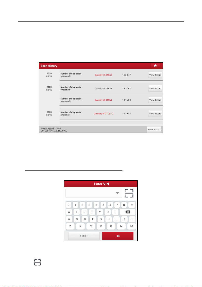
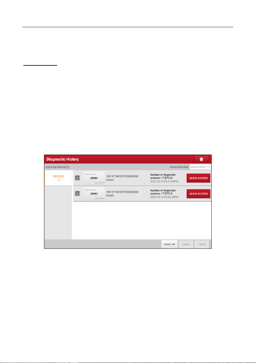
5.5 Diagnostic History
This function enables users to directly get access to the previously tested
vehicle’s diagnostic records in details, so users can resume from the last
operation, without starting from scratch.
Tap
Diagnostic History
on the Job menu screen, all diagnostic records will be
listed on the screen in date sequence.
• Tap certain vehicle model to view the details of the last diagnostic report.
• To delete certain diagnostic history, select it and then tap
Delete
. To
delete all historical records, tap
Select All
and then tap
Delete
.
• Tap
Quick access
to directly navigate to the function selection page of
last diagnostic operation. Choose the desired option to proceed.

LAUNCH
53
6 Service (Reset) Function
This module provides an easy dial to quickly access the most commonly
performed service functions. It offers coding, reset, relearn and more service
functions, to help vehicles get back to functional status after repair or
replacement.
The following service functions described below are based on the latest
information available at the time of publication.
Due to continuing improvements, the available service functions are subject to
change at any time. To enjoy more service functions, you are suggested to check
for updates on a regular basis.
6.1 Maintenance Light Reset (Oil Reset)
This function enables you to reset the oil service for the engine oil life system,
which calculates an optimal oil life change interval depending on the vehicle
driving conditions and weather events.
It needs to be performed in the following cases:
1. If the service lamp is on, run car diagnostics first for troubleshooting. After
that, reset the driving mileage or driving time, so as to turn off the service
lamp and enable a new driving cycle.
2. If the service lamp is not on, but you have changed the engine oil or electric
appliances that monitor oil life, you need to reset the service lamp.
6.2 Electronic Parking Brake Reset (BRAKE RESET)
This function enables you to reset the brake pad after replacing the brake pad.
It needs to be performed in the following cases:
1. The brake pad and brake pad wear sensor are replaced.
2. The brake pad indicator lamp is on.
3. The brake pad sensor circuit is short, which is recovered.
4. The servo motor is replaced.

LAUNCH
54
6.3 Steering Angle Reset (SAS Reset)
This function enables you to reset the steering angle, after replacing the steering
angle position sensor, replacing steering mechanical parts (such as steering
gearbox, steering column, end tie rod, steering knuckle), performing four-wheel
alignment, or recovering car body.
To reset the steering angle, first find the relative zero point position for the car to
drive in straight line. Taking this position as reference, the ECU can calculate the
accurate angle for left and right steering.
6.4 ABS Bleeding
This function allows you to perform various bi-directional tests to check the
operating conditions of Anti-lock Braking System (ABS).
It needs to be performed in the following cases:
1. When the ABS contains air.
2. When the ABS computer, ABS pump, brake master cylinder, brake cylinder,
brake line, or brake fluid is replaced.
6.5 Crank Position Sensor Adaptive Learning (GEAR LEARN)
This function can perform gear learning for the car, to turn off the related
Malfunction Indicator Light (MIL).
It needs to be performed in the following cases:
1. After the engine ECU, crankshaft position sensor, or crankshaft flywheel is
replaced.
2. The DTC “tooth not learned” is present.
6.6 Anti-theft Matching (IMMO)
This function can match the anti-theft key after replacing the ignition key, ignition
switch, instrument cluster, engine control unit (ECU), body control module
(BCM), and remote control battery.

LAUNCH
55
6.7 Injector Coding (INJECTOR)
This function enables you to write injector actual code or rewrite code in the ECU
to the injector code of the corresponding cylinder, so as to more accurately
control or correct cylinder injection quantity.
It needs to be performed in the following cases:
After the ECU or injector is replaced.
6.8 Battery Matching (BAT. RESET)
This function enables you to perform a resetting operation on the monitoring unit
of vehicle battery, in which the original low battery fault information will be
cleared and battery matching will be done.
It needs to be performed in the following cases:
1. The main battery is replaced.
2. The battery monitoring sensor is replaced.
6.9 DPF Regeneration (DPF REG.)
This function enables you to clear PM (Particulate Matter) from the DPF filter
through continuous combustion oxidation mode (such as high temperature
heating combustion, fuel additive or catalyst reduce PM ignition combustion) to
stabilize the filter performance.
It needs to be performed in the following cases:
1. The exhaust back pressure sensor is replaced.
2. The PM trap is removed or replaced.
3. The fuel additive nozzle is removed or replaced.
4. The catalytic oxidizer is removed or replaced.
5. The DPF regeneration MIL is on and maintenance is performed.
6. The DPF regeneration control module is replaced.

LAUNCH
56
6.10 Throttle Matching (ELEC. THROTTLE RLRN)
This function enables you to make initial settings to throttle actuators and returns
the learned values stored on ECU to the default state. Doing so can accurately
control the actions of regulating throttle (or idle engine) to adjust the amount of
air intake.
6.11 Gearbox Matching (GEARBOX)
This function enables you to complete the gearbox self-learning to improve gear
shifting quality.
It needs to be performed in the following cases:
When the gearbox is disassembled or repaired.
6.12 Headlight Matching (AFS RESET)
This function enables you to initialize the adaptive headlamp system.
6.13 Sunroof Initialization (SUNROOF)
This function enables you to set the sunroof lock off, closed when it rains, sliding
/ tilting sunroof memory function, temperature threshold outside the car etc.
6.14 Suspension Level Calibration (SUS RESET)
This function enables you to adjust the height of the body.
It needs to be performed in the following cases:
1. When replacing the body height sensor, or control module in the air
suspension system.
2. When the vehicle height is incorrect.
6.15 EGR Adaption
This function is used to learn the EGR (Exhaust Gas Recirculation) valve after it
is cleaned or replaced.

LAUNCH
57
6.16 Seats Calibration
This function is applied to match the seats with memory function that are
replaced and repaired.
6.17 Tyre Reset
This function is used to set the size parameters of the modified or replaced tire.
6.18 Coolant Bleed
Use this function to activate the electronic water pump before venting the cooling
system.
6.19 AdBlue Reset
After the diesel exhaust treatment fluid (car urea) is replaced or filled up, urea
reset operation is required.
6.20 NOx Sensor Reset
NOx sensor is a sensor used to detect the content of nitrogen oxides (NOx) in
engine exhaust. If the NOx fault is re-initialized and the NOx catalytic converter
is replaced, it is necessary to reset the catalytic converter learned value stored
in the engine ECU.
6.21 AC System Relearn/Initialization
AC system relearn/initialization must be performed when the vehicle AC ECU or
actuator is replaced or the ECU memory is lost.
6.22 High Voltage Battery Detection (HIGH VOLTAGE
BATTERY)
This function is used for high voltage battery diagnosis and status information

LAUNCH
58
detection.
6.23 Windows Calibration
This function is used to perform door window matching to recover the ECU initial
memory, and recover the automatic ascending and descending function of
power window.
6.24 Language Change
This function is used to change system language of vehicle center console.
6.25 A/F Reset
This function is applied to set or learn air/fuel rate parameters.
6.26 Transport Mode
To lower vehicle power consumption, user may perform the following operations:
limit vehicle speed, not wake up the network for door open and disable remote
key etc. In this case, deactivating transport mode is needed to recover vehicle
being normal.
6.27 Stop/Start Reset
This function is used to open or close the automatic Start/Stop function via
setting the hidden function in ECU (The precondition is vehicle equipped with
hidden function and hardware support).
6.28 Intelligent Cruise Control System Reset
This function is used to matching the intelligent cruise control module after it is
replaced or repaired.

LAUNCH
59
6.29 Engine Power Balance Monitoring
This function is used to monitor crankshaft acceleration in the power stroke of
each cylinder, to determine the relative power provided by each cylinder.
6.30 Gas Particulate Filter (GPF) Regeneration
This function is used to perform the GPF replacement or regeneration after the
fuel consumption is increased and engine output power is reduced resulting
from a long time service of the GPF.
6.31 Motor Angle Calibration
This function is used to perform the motor angle calibration when the rotor
position detected by the motor angle position sensor is different from the actual
rotor field position.
6.32 Tire Pressure Reset (TPMS RESET)
This function can reset the tire pressure and turn off the tire pressure fault
indicator when the car tire pressure fault indicator light is on.
6.33 IMMO Programming
This function enables you to perform read-write function for vehicle key,
EEPROM, MCU, and EEPROM/FLASH data of vehicle engine/gearbox ECU.
6.34 Turbocharging Matching
This function Learning after replacing the parts of boost system, or reset the
learning value of turbocharger.
6.35 Clutch Matching
This function is used for clutch pedal position switch or switch learning.
It needs to be performed in the following cases:

LAUNCH
60
After replacement of the electrical control unit, replacement/disassembly of
gearbox, and the replacement of the clutch.
6.36 FRM Matching
This function can clear the fault of light short circuit.
6.37 ECU Reset
This function can reset the control unit after executing the coding function of the
certain subsystem.

LAUNCH
61
7 Software Update
This module enables you to update the diagnostic software & App and frequently
used software.
7.1 Update Diagnostic Software & APP
Go to
Software Update
on the Job Menu and tap the
Downloaded
tab.
The
Available
tab displays a list of software that can be updated. Under it, all
software is categorized into three kinds:
•
Common software
: mainly includes some common apps that are associated
with the diagnostic app. The software of this kind always stays at the top of
the list, which can be deselected manually (excluding the system app, such
as firmware and ECU aid).
•
Frequently used vehicle software
: refers to the diagnostic software that is
frequently used, including the vehicle diagnostic software and Reset software.
It is generally displayed following the
Common software
list.
•
Other vehicle software
: refers to the diagnostic software that is rarely used
or never used. It is generally displayed following the
Frequently used
software
list.
1). If the user does not download any diagnostic software during the sign-up
process, all diagnostic software is selected by default. Tap
Update
to start
downloading.
2). If the user downloaded all/some vehicle software during the sign-up process
and had it serviced for a long period of time, only the frequently used
software is selected. Tap
Update
to start downloading. Other vehicle
software that is rarely used will also be listed under the
Available
tab, but it
is not selected at default.
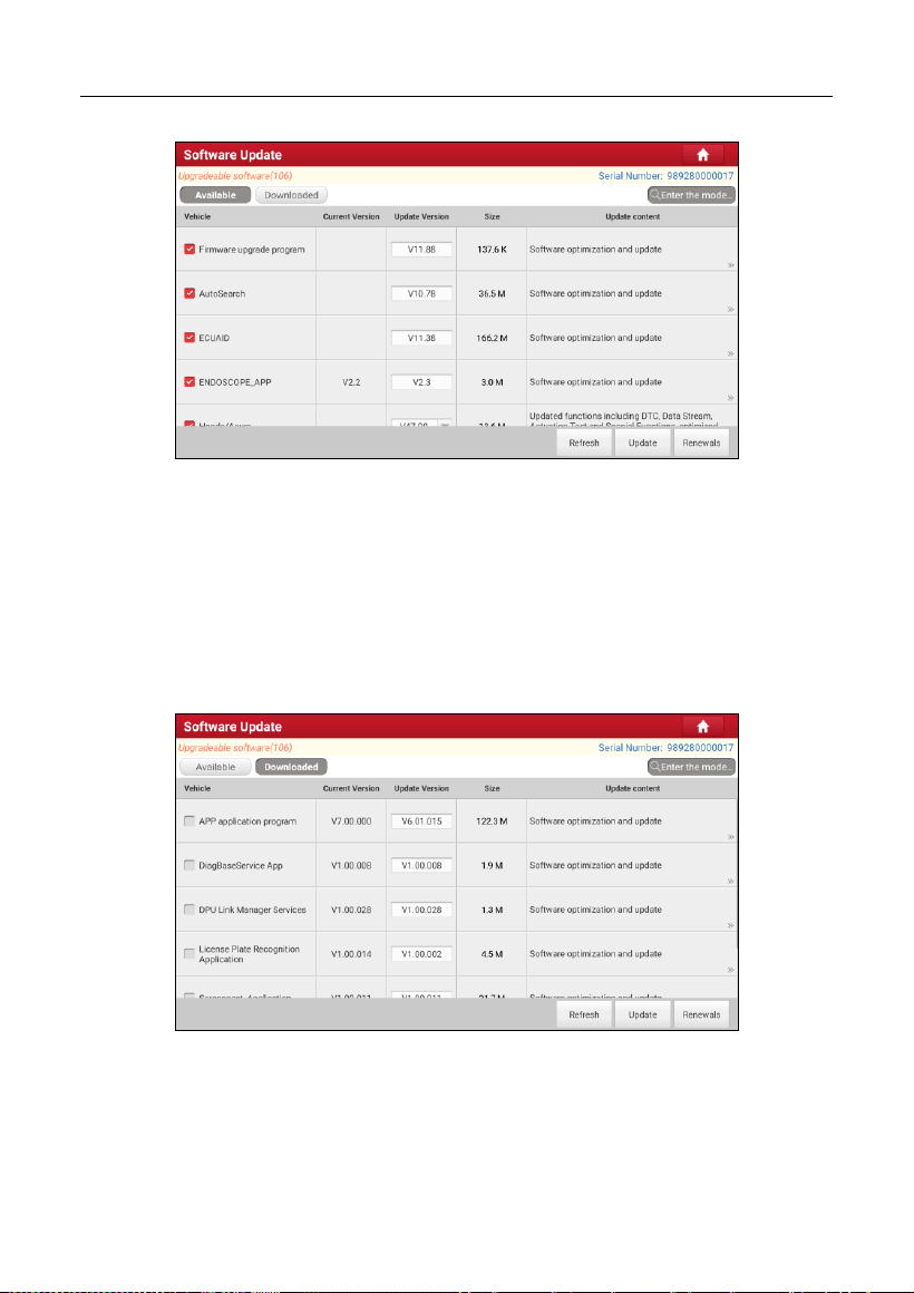
LAUNCH
62
To download certain software that is not frequently used, check the box before
the vehicle model. Tap
Update
to start downloading.
Once download is finished, the software packages will be installed automatically.
7.2 Update Frequently Used Software
If the user only intends to update the frequently used software, go to Software
Update and tap the
Downloaded
tab.
Tap
Update
to start downloading. Once download is finished, the software
packages will be installed automatically.
7.3 Renew Subscription
If the software subscription is due or expires, the system will prompt you to

LAUNCH
63
renew your subscription.
Tap “Renewals” to open the Mall, and follow the on-screen prompts to finish the
subscription.

LAUNCH
64
8 Add-on Modules
8.1 ADAS (Calibration)
This module enables you to effectively and accurately calibrate a wide range of
camera-based & radar-based driver assistance systems, e.g. the front camera
for the lane departure warning system, the radar sensor for the ACC (Adaptive
Cruise Control) or the camera for adaptive headlights. It needs to work with the
specific ADAS calibration tool (sold separately).
For more details, please refer to the User Manual included with the module.
8.2 TPMS
This module allows you to configure the tablet as TPMS activation & diagnostic
tool, which provides the ability to trigger TPMS sensor, program TPMS sensor,
perform the relearning procedure. It needs to work with the compatible TSGUN
device (sold separately).
For more details, please refer to the User Manual included with the module.
8.3 Oscilloscope
This module can make the auto repair technician quickly judge the faults on
automotive electronic equipment and wiring.
For more details, please refer to the User Manual included with the module.
8.4 S2-2 Sensorbox
This module is specially designed to diagnose and simulator vehicle sensor
faults quickly and conveniently. It needs to work with the compatible S2-2
Sensorbox (sold separately).
For more details, please refer to the User Manual included with the module.
8.5 S2-2 Multimeter
This module allows you to measure the physical parameters such as voltage,
resistance, frequency etc. It utilizes the same hardware as the S2-2 Sensorbox.

LAUNCH
65
For more details, please refer to the User Manual included with the S2-2
Sensorbox.
8.6 BST360 (Battery Tester)
This module allows you to fix battery detection faster and easier. It needs to
work with the specific Bluetooth battery tester (sold separately).
For more details, please refer to the User Manual included with the module.
8.7 Immobilizer Programmer
This module allows you to perform the read-write function for vehicle keys,
EEPROM, MCU, and EEPROM/FLASH of vehicle engine and gearbox ECU. It
needs to work with the specific immobilizer programmer (sold separately).
For more details, please refer to the User Manual included with the module.
8.8 Videoscope
This module allows you to check those unseen parts of engine, fuel tank,
braking system. It needs to work with the compatible Videoscope device (sold
separately).
For more details, please refer to the User Manual included with the module.

LAUNCH
66
9 User Info
This function allows users to manage personal information and VCI.
9.1 My Report
This option is used to view, delete or share the saved reports.
Tap
Report
, there are total 3 options available.
In case the DTC result is saved on Read Trouble Code page, the files will be
listed under
Health Reports
tab.
If user records the running parameters while reading data stream, the tablet will
save the file which appears under
Recorded Data
tab.
Remote Reports
lists all diagnostic reports generated in process of remote
diagnosis.
9.2 VCI
This option allows you to manage all your activated VCI devices.
If several VCI devices are activated on this tool, a list of VCIs will be displayed
on the screen. Once you choose the VCI that belongs to other account, you
have to log out, and then input the right account to continue.
9.3 VCI Management
This option is used for the tablet to deactivate pairing up with the VCI device via
Bluetooth.
9.4 Activate VCI
This item lets you activate the VCI device in case you ignore the Activate VCI
step in process of the product sign-up.

LAUNCH
67
Input the Serial Number and Activation Code, and then tap
Activate
to activate
the VCI.
9.5 Firmware Fix
Use this item to upgrade and fix diagnostic firmware. During fixing, please do not
cut power or switch to other interfaces.
9.6 Sample
This feature allows you to manage the recorded data stream sample files.
9.7 My Order
This item allows you to check the status of all your orders.
9.8 Subscription Renewal Card
This item is used to check the status of the subscription renewal card.
Input the 12-digit subscription renewal card number. Tap
Search
to get the
search result.
9.9 Profile
Use this item to view and configure personal information.
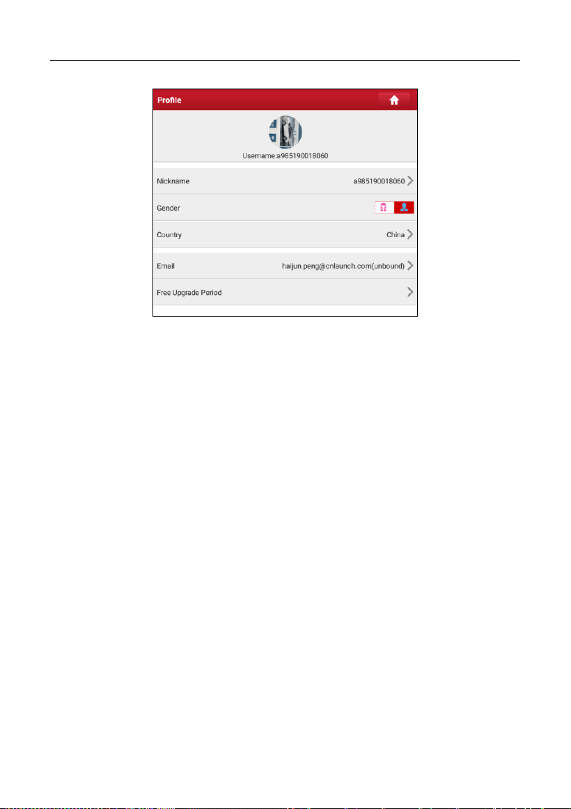
LAUNCH
68
• Tap the user image to change it.
• Tap > next to Upgrade Period to check the due date of all diagnostic
software.
9.10 Change password
This item allows you to modify your login password.
9.11 Settings
It enables you to make some application settings and view software version
information etc.
9.11.1 Units
It is designed to configure the measurement unit. Metric System and English
System are available.
9.11.2 Shop Information
This option lets you define your shop information. It mainly includes Workshop,
Address, Telephone, Fax and License Plate.
After inputting, tap
Save
.
Once you saved the shop information, it will be entered automatically in the Add
Information box every time you save the diagnostic report.
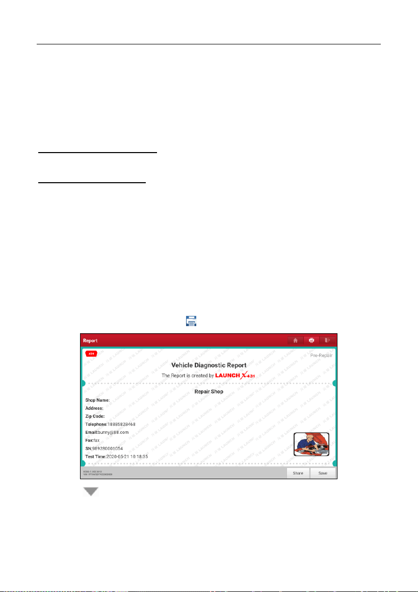
LAUNCH
69
9.11.3 Printer Set
This option is designed to establish a wireless connection between the tablet
and the Wi-Fi printer (sold separately) while performing printing operations.
The App is compatible with the
LAUNCH Wi-Fi Printer
(sold separately) and
System
(external printer).
For LAUNCH Wi-Fi printer
, refer to the user manual included with the printer to
configure it.
For other Wi-Fi printers
,
Before printing, make sure the following conditions are met:
• The Wi-Fi printer is powered on and working normally.
• The print service plug-in associated with the printer is already installed on the
tablet (Go to Google Play or use the Browser to download and install it).
Follow the steps below to proceed:
1. Set the default printer as
System
.
2. Go to
Other Modules -> Tablet Settings -> Network & Internet -> Wi-Fi
,
set the WLAN switch to Off.
3. On the report details page, tap .
4. Touch next to
Select a printer
on the upper left corner of the screen.
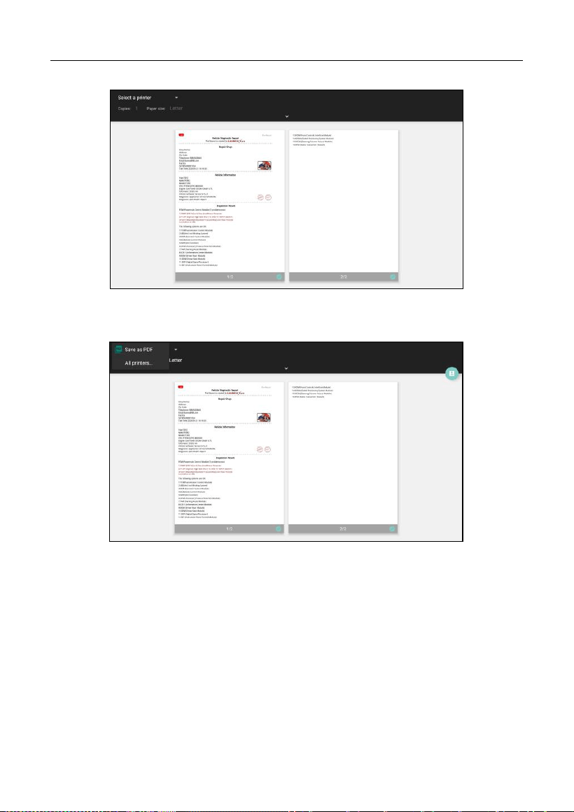
LAUNCH
70
5. Select
All Printers -> Add printer
and enable the installed printer service,
the system starts searching for all available Wi-Fi printers of the brand.
6. Select the desired Wi-Fi printer from the list. If the chosen Wi-Fi printer
hotspot is open, the tablet can connect it directly. If it is encrypted, a
password may be required. Refer to the Wi-Fi printer user manual to get the
default password.
7. Now the printer is ready for printing.
8. Alternatively, you can also choose
Save as PDF
to save the current
diagnostic report as a PDF file for later printing.
9.11.4 Orientation
The option is used to set the screen display orientation.
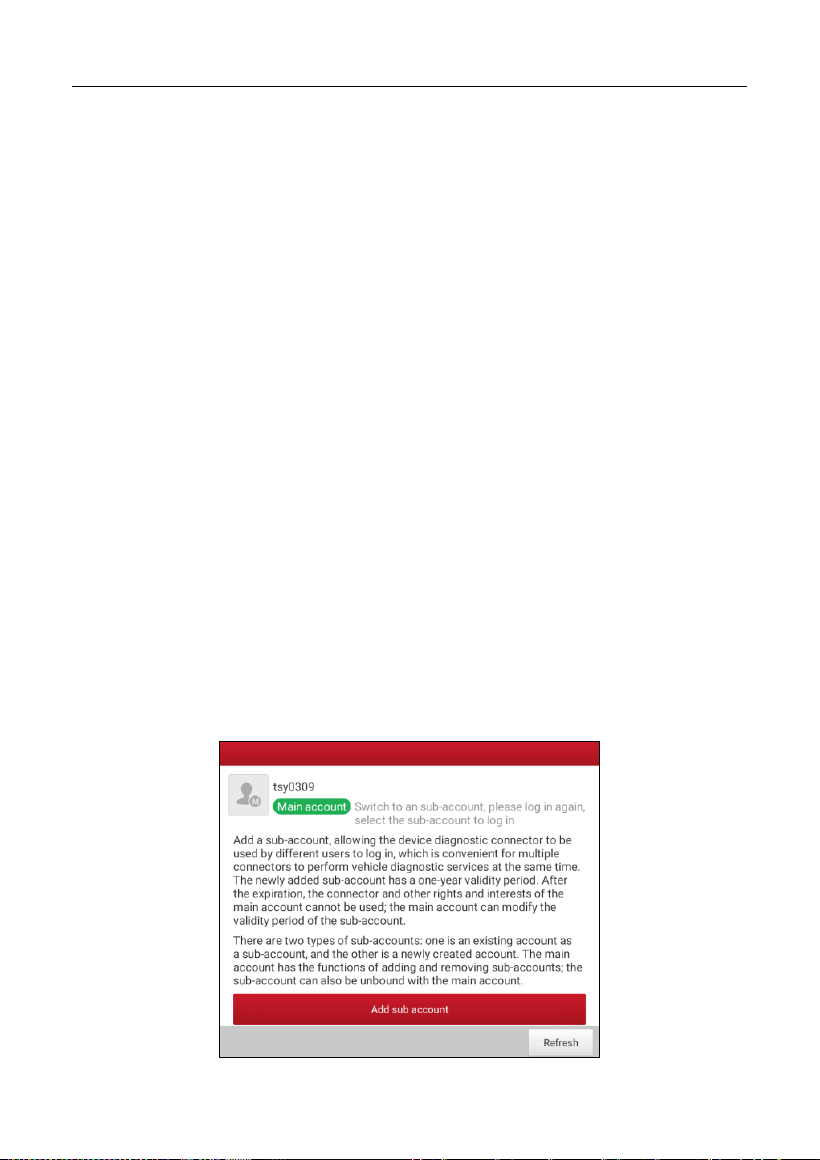
LAUNCH
71
9.11.5 Clear Cache
This option allows you to clear the App cache. Clearing the cache will restart the
App.
9.11.6 About
The software version information and disclaimer are included.
9.11.7 Diagnostic Software Auto Update
This option is used to set whether automatic update function is ON.
9.11.8 Device Account Management
This option is used to manage the sub-accounts. The added sub-account allows
the VCI connector to be used by different users to log in the tool, which is
convenient for multiple VCIs to perform diagnostic service at the same time.
The newly added sub-account has a one-year validity period. After the expiration,
the VCI bound to the sub-account cannot be used and the sub-account will no
longer enjoy the rights and interests of the main account. The main account can
modify the validity period of the sub-account.
There are two types of sub-accounts: one is an existing account and the other is
a newly created account. The main account has the functions of adding and
removing sub-accounts, the sub-account can also be unbound from the main
account.
Tap Device account management, the following screen will appear:
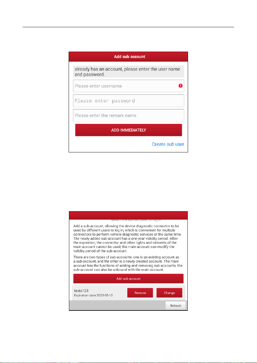
LAUNCH
72
Tap Add sub account, the following popup will appear:
• If you already have an account, please enter the user name and password.
After inputting, tap Add Immediately to add it as a sub-account.
• If you have not registered any account, tap Create sub user. Enter the user
name and password, and then tap Add Immediately to add it as a
sub-account.
After adding the sub-account, the following screen will appear:
To unbind it from the main account, tap Remove. To revise the validity period,
tap Change.

LAUNCH
73
9.11.9 Login/Logout
To logout the current user ID, tap
Logout
.
To login the system again, tap
Login
.
9.12 Diagnostic Software Clear
This item allows you to hide/clear the diagnostic software that is not frequently
used.
Note: Removing software may completely delete the software from the tablet. If
some software is not used and the tablet runs out of space, you can use this feature to
remove it.

LAUNCH
74
10 FAQ
1. How to save power?
Please turn off the screen while the tool keeps idle.
Set a shorter standby time.
Decrease the brightness of the screen.
If WLAN connection is not required, please turn it off.
Disable GPS function if GPS service is not in use.
2. Communication error with vehicle ECU?
Please confirm:
1. Whether diagnostic connector is correctly connected.
2. Whether ignition switch is ON.
3. If all checks are normal, send vehicle year, make, model and VIN number to
us using Feedback feature.
3. Failed to enter into vehicle ECU system?
Please confirm:
1. Whether the vehicle is equipped with this system.
2. Whether the VCI dongle is correctly connected.
3. Whether ignition switch is ON.
4. If all checks are normal, send vehicle year, make, model and VIN number to
us using Feedback feature.
4. How to download the diagnostic App after resetting the tablet?
Note: Before registration, please make sure the network is properly connected.
After the tablet has been successfully reset, follow the steps below to download
the App:
1. Launch the browser and the default official Launch website opens (If a blank
page pops up, just type in www.x431.com in the input bar).
2. Tap “Login”, input the username and password and tap “Log In.”

LAUNCH
75
3. Make sure that the serial number is correct, tap “APP application program”
and tap the Download icon to start downloading.
4. After the download is complete, follow the on-screen instructions to install it.
5. After installation, use the existing username and password to login and go to
update center to download the diagnostic software.
5. What to do if the language of vehicle diagnostic software does not
match the system language?
English is the default system language of the tool. After the system language is
set to the preference language, please go to the update center to download the
vehicle diagnostic software of the corresponding language.
If the downloaded diagnostic software is still displayed in English, it indicates
that the software of the current language is under development.
6. How to retrieve the login password?
Please follow below steps to proceed in case you forgot the login password:
1. Tap the application icon on the home screen to launch it.
2. Tap
Login
on the upper right corner of the screen.
3. Tap
Retrieve Password
.
4. Input product S/N and follow the on-screen prompts to retrieve the password.
7. How to backup system data?
There are two USB ports available on this tool: USB Type A and USB Type C.
The former is reserved for external USB storage device and the latter is used
with PC when performing system data backup. It is strongly recommended to
use the USB Type C interface for this operation.
A. If exchanging data with an external USB storage device,
1. Plug the USB storage device into the USB Type A interface.
2. Swipe the screen from the top to select the USB drive.
3. Now you can exchange the data with the USB storage device.
B. If exchanging data with a PC,
1. On the home screen, tap
Settings
->
USB Management
. Slide the USB

LAUNCH
76
Switch to OFF to enable the USB Type C interface.
Note: By default, the USB Switch is set as ON. In this case, the USB Type C
interface is only for charging and disabled for data exchange.
2. Plug the Type C end of the included data cable into the Type C port of the
tool, and the other end to the USB port of the PC.
3. After the PC successfully identifies the tool, you can perform data backup.

Warranty
This warranty is expressly limited to persons who purchase LAUNCH
®
products
for purposes of resale or use in the ordinary course of the buyer’s business.
LAUNCH
®
electronic product is warranted against defects in materials and
workmanship for one year (12 months) from date of delivery to the user.
This warranty does not cover any part that has been abused, altered, used for a
purpose other than for which it was intended, or used in a manner inconsistent
with instructions regarding use. The exclusive remedy for any automotive meter
found to be defective is repair or replacement, and LAUNCH shall not be liable
for any consequential or incidental damages.
Final determination of defects shall be made by LAUNCH in accordance with
stipulated procedures.
Order Information
Replaceable and optional parts can be ordered directly from your authorized tool
supplier. Your order should include the following information:
Quantity
Part number
Item description
Customer Service
If you have any questions on the operation of the unit, please contact local
dealer, or customer service center:
Tel: 1-888-756-2936
E-mail: Tech_Launchoriginal@outlook.com

Statement:
LAUNCH reserves the rights to make any change to product designs and
specifications without notice. The actual object may differ a little from the
descriptions in the manual in physical appearance, color and configuration. We
have tried our best to make the descriptions and illustrations in the manual as
accurate as possible, and defects are inevitable, if you have any question,
please contact local dealer or after-sale service center, LAUNCH does not bear
any responsibility arising from misunderstandings.