
1
User Manual
8000 Series Network Camera
Version: V2.3
Date: September, 2022

2
Statement
The user manual is for reference only. Detailed information is subject to the actual
products.
The product and description in this document are subject to change at any time without
prior notice.
Screenshots included in the manual are extracted from other machines and are for
reference only.
Should you have any questions, or if you need the latest firmware and additional
information, please contact with the after-sales service department.
Precautions
The following describes proper use of the device and precautions against risks as well as
measures that need to be strictly followed to avoid property damage.
Please use the cameras in an environment where the temperature and humidity are within
the recommended range. Check if the power supply works normally before operation.
Do not hit or drop the product.
Do not install the product at a dusty or moist location, or a place covered by strong
electromagnetic radiation.
Do not allow liquid leaking into the device. When you do not use the product, please place a
dust cover on the image sensor.
Do not disassemble the product without authorization

2
Contents
0 Quick Installation Guide(only SD card model) ............................................................................4
1 Login Interface .............................................................................................................................7
2 Live Videos ..................................................................................................................................9
2.1 Full-screen Preview .......................................................................................................... 9
2.2 Electronic Zoom-in ..........................................................................................................10
2.3 PTZ control ......................................................................................................................10
3 Playback .................................................................................................................................... 12
4 File Management .......................................................................................................................13
4.1 Search .............................................................................................................................13
4.2 Preview Capture ............................................................................................................. 14
4.3 Playback Capture ........................................................................................................... 14
4.4 Playback Backup ............................................................................................................ 14
4.5 File Capture .....................................................................................................................14
4.6 Preview Videos ............................................................................................................... 14
4.7 SD Card Link Capture .....................................................................................................14
4.8 Backup Video Play ..........................................................................................................14
5 Parameter ..................................................................................................................................16
5.1 Device Information ..........................................................................................................16
5.2 QR Code ......................................................................................................................... 16
5.3 PTZ Settings ................................................................................................................... 17
5.4 Time Settings .................................................................................................................. 17
5.5 Audio Settings .................................................................................................................18
5.6 Display Settings .............................................................................................................. 19
5.7 Streams ...........................................................................................................................20
5.8 ROI Settings ....................................................................................................................21
5.9 Image Parameters .......................................................................................................... 21
5.10 Motion Detection ...........................................................................................................24
5.10.1Smart Motion ...............................................................................................................25

3
5.11 Video Tampering .......................................................................................................... 26
5.12 Privacy Mask .................................................................................................................28
5.13 Target Counting ............................................................................................................ 28
5.14 Object Left / Lost ...........................................................................................................30
5.15 Area Detection (Intrusion Detection) ............................................................................31
5.16 Line Crossing (Tripwire) ............................................................................................... 32
5.17 Video Plan .....................................................................................................................34
5.18 Network Settings ...........................................................................................................35
5.19 HTTP/HTTPS ................................................................................................................36
5.20 Management Platform .................................................................................................. 36
5.21 Multicast Configuration ................................................................................................. 37
5.22 DDNS Settings ..............................................................................................................37
5.23 UPnP Settings ...............................................................................................................39
5.24 Email Settings ............................................................................................................... 39
5.25 FTP Settings ................................................................................................................. 40
5.26 SNMP Settings ..............................................................................................................41
5.27 Alarm Input ....................................................................................................................41
5.28 Alarm Output .................................................................................................................43
5.29 Exception ...................................................................................................................... 43
5.30 User Management ........................................................................................................ 44
5.31 System Update ............................................................................................................. 45
5.32 Auto Reboot .................................................................................................................. 46
5.33 Storage Management ................................................................................................... 46
5.34 Restore ..........................................................................................................................47
5.35 Local Settings ............................................................................................................... 48
5.36 Developer ......................................................................................................................50
6. Log Search ............................................................................................................................... 51
7 Alarm ......................................................................................................................................... 52
8 Exit .............................................................................................................................................52
9 FAQ ........................................................................................................................................... 53
4
0 Quick Installation Guide(only SD card
model)
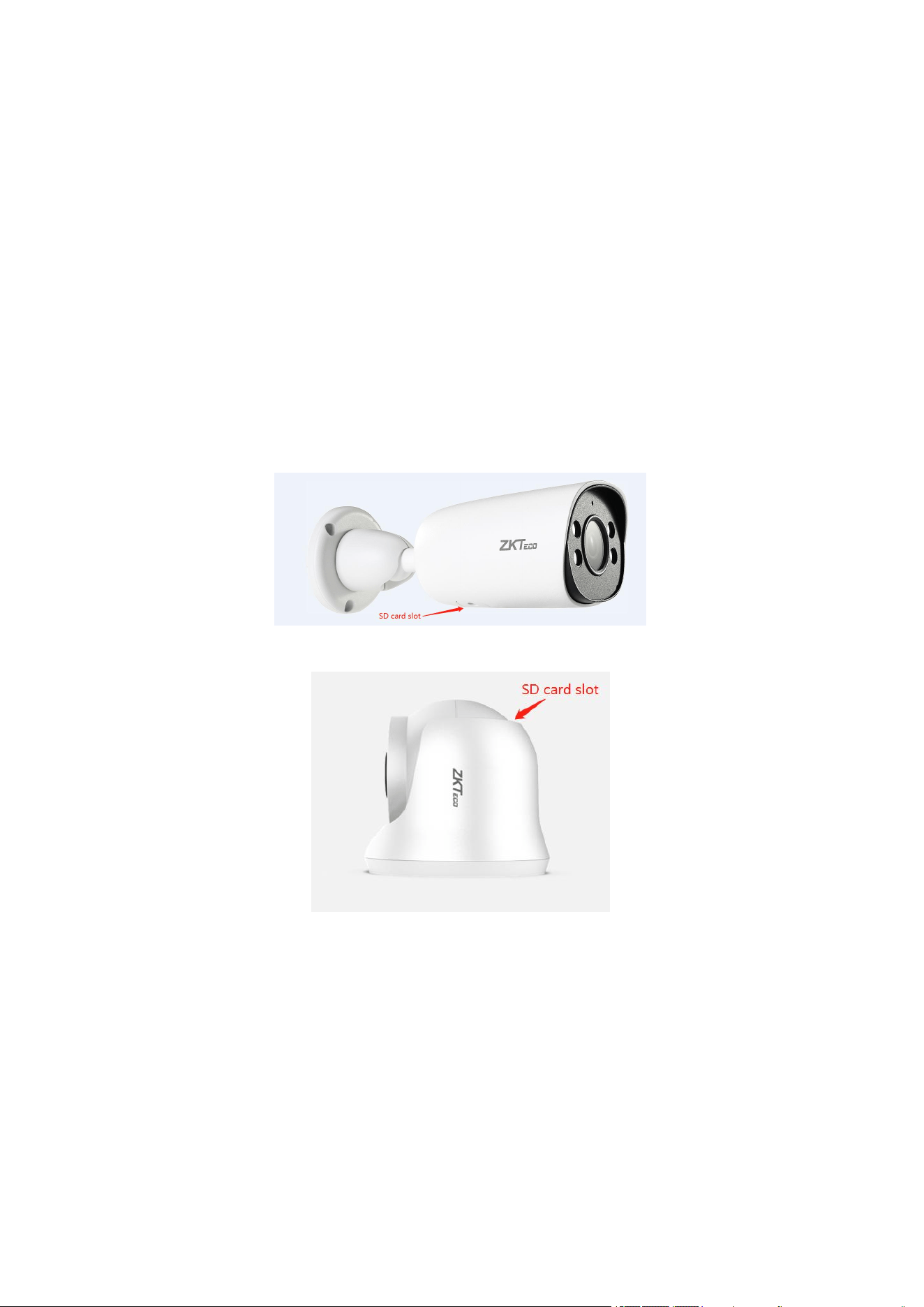
Step 1, disassemble.
In order to ensure that the Micro-SD card will not be easily touched and loosened, the camera
has designed the Micro-SD card slot inside the camera. When installing the Micro-SD card,
user needs to remove the Micro-SD card slot cover at the bottom of camera (for the Conch
model, you need to rotate the camera base to expose the Micro-SD card slot).
Bullet Type:
Turret Type:
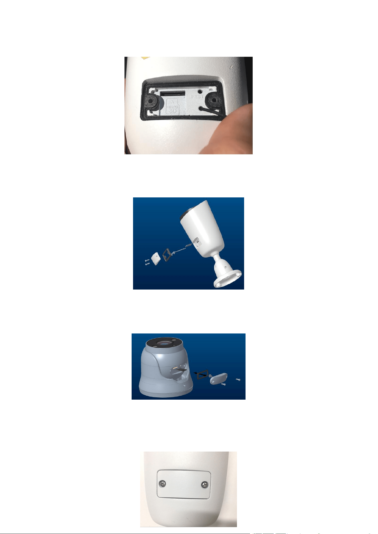
Step 2, unscrew the screw, open the cover, can see the internal Micro-SD slot.
5
Step 3, install the Micro-SD card in the correct direction and insert it into the slot.
Bullet Type:
Turret Type:
Step 4, close the cover and tighten the screws.
6
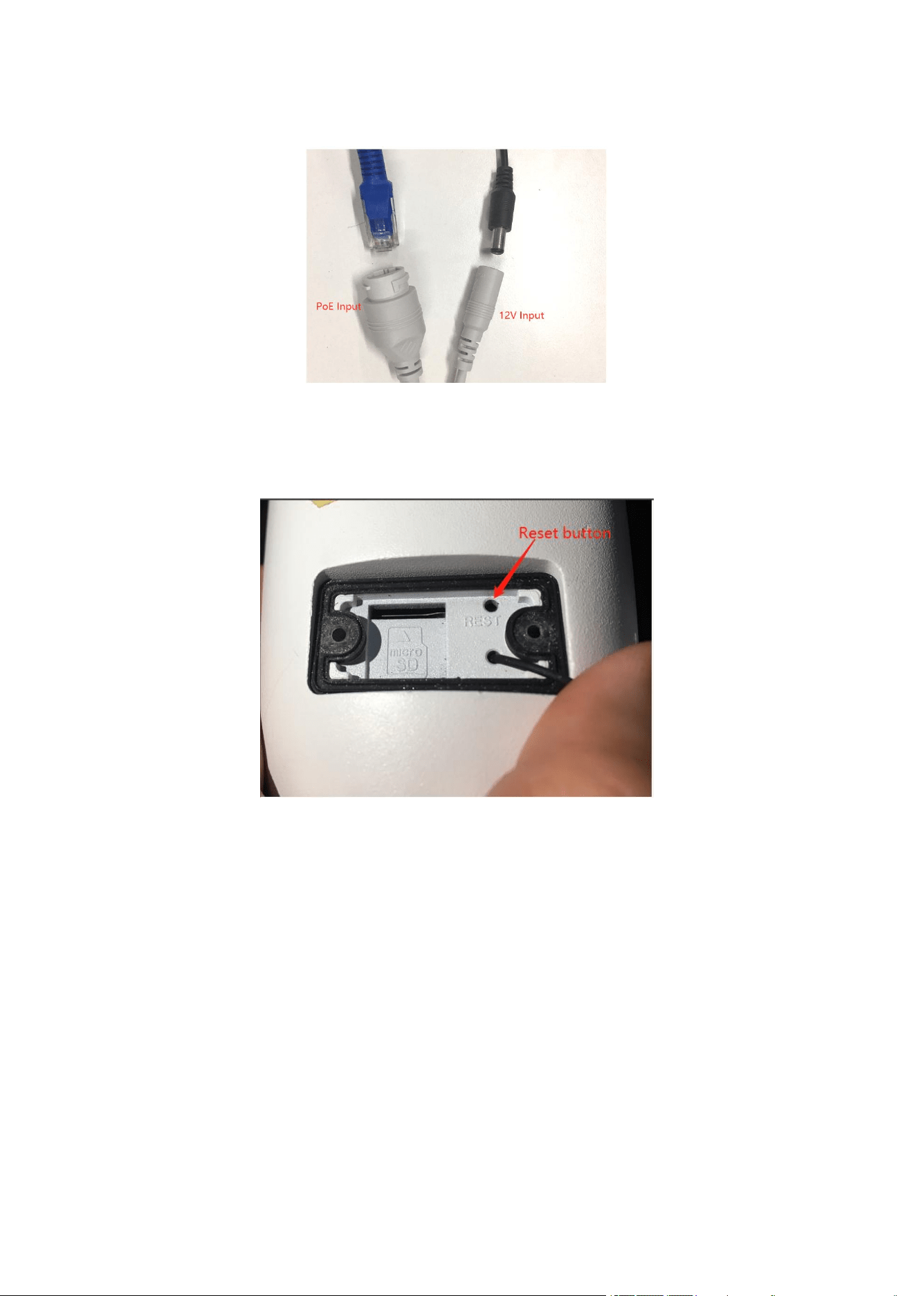
Step 5, power on the camera by PoE or 12V DC.
Note: The small round hole next to the Micro-SD card slot is the factory reset button (as
picture . In the power-on state, press and hold the small thimble for 3 seconds, and the camera
will restore the factory default settings.
7
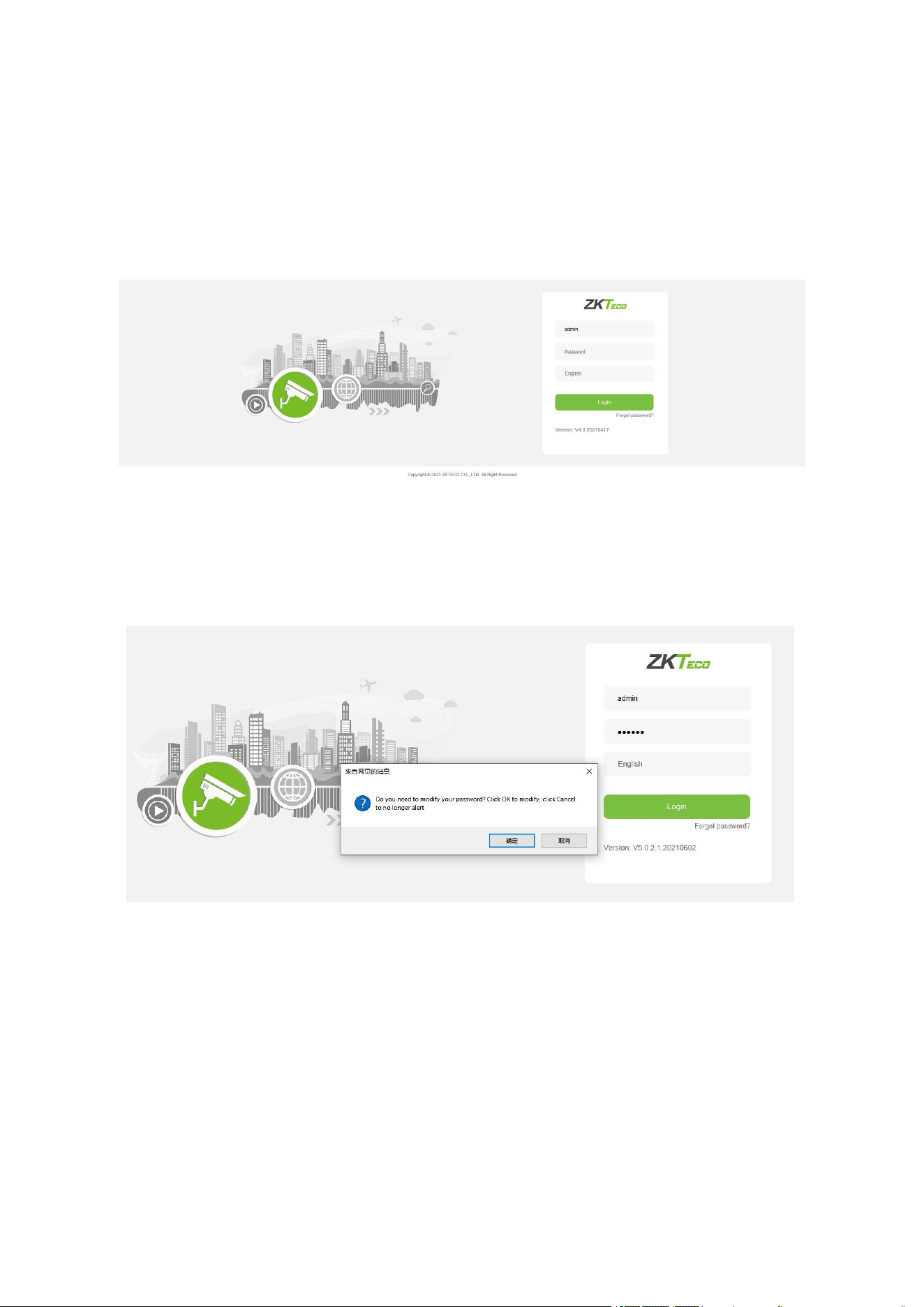
1 Login Interface
Input the IP address of the front-end device in the IE browser (the default IP address is
192.168.1.86) to access the login interface as shown in the following picture:
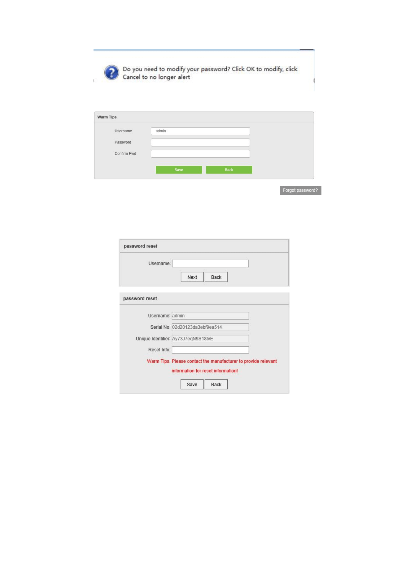
input username and password then click on “Login”, then the system will prompt a message
asking whether or not to change the password, as shown in the following figure:
User Name: admin (default setting).
Password: 123456 (default setting); users may modify the password according to the
instructions.
Language: English, simplified Chinese.
Note: For account security, users will be prompted to reset the password when
they first login.
8
Note: if a user forgets the login password, one may click on , then the
following window will pop up. The default user name is “admin”. Click on “Next” to restore
the password to factory settings according to the prompt.
9
2 Live Videos
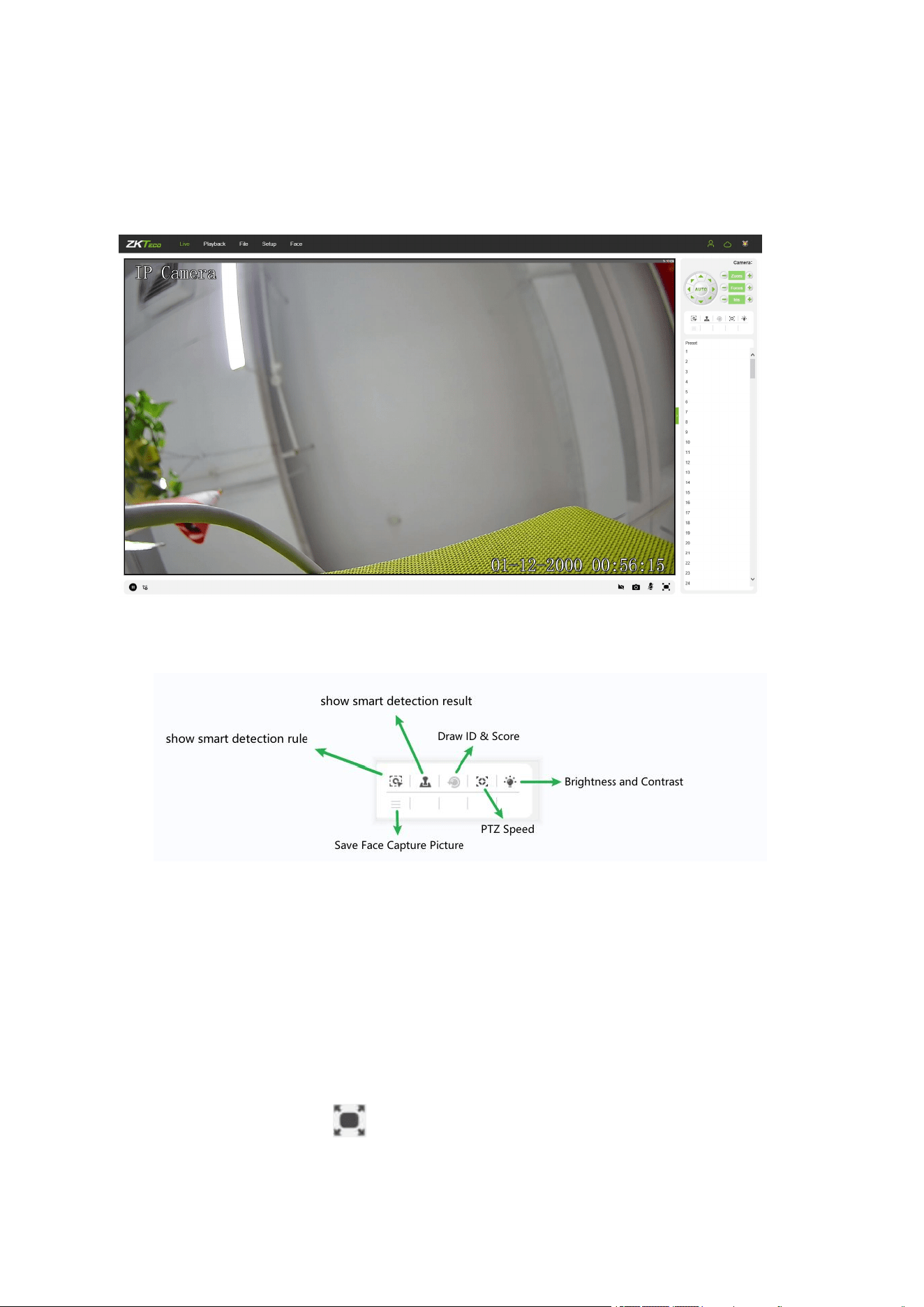
After logging in, you will enter the live video interface, as shown in the following figure.
Note: You have to insert a TF card first to access the full function display interface;
otherwise, the system will only show you the simplified version.
Show Smart Detection Rule: Show the rules of smart detection
Show Smart Detection Result: Show the result of smart detection
Save Face Capture Pictrue: Save face capture instantly
Draw ID & Score: Shows the face's randomly assigned ID and quality score
2.1 Full-screen Preview
Click on the full-screen icon in the lower right corner to get a full-screen preview. Or,
you may right-click to access (and exit) the full screen display on the preview interface
10
2.2 Electronic Zoom-in
You may zoom in the preview image by scrolling the mouse wheel, as shown in the following
figure:
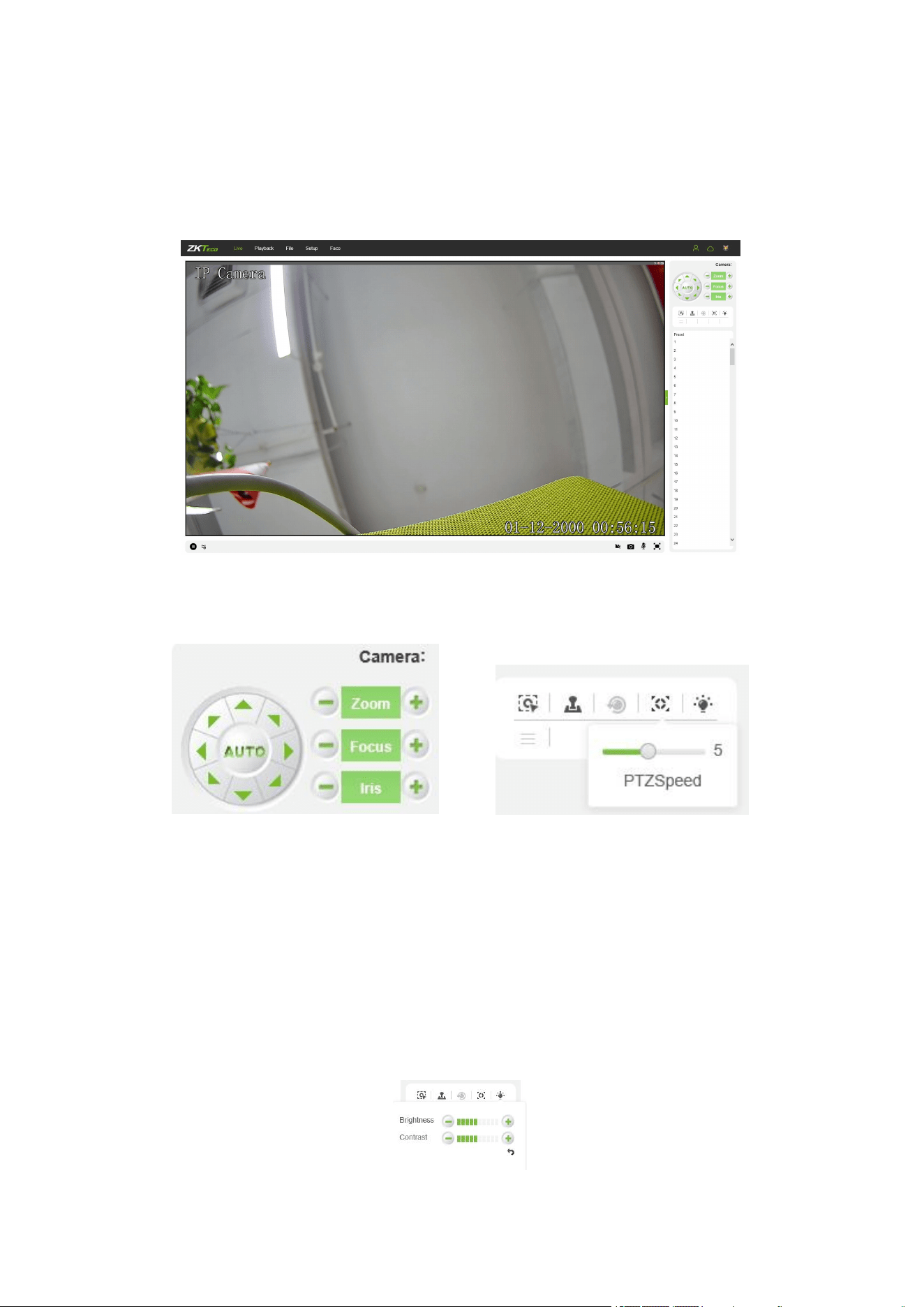
2.3 PTZ control
PTZ Control: To use eight directional keys to change the image orientation or click on the
“AUTO” button to allow auto-rotation.
Zoom In/ Out: To adjust the extent of zooming in or out.
Focus: To adjust the size of focus.
Iris: To adjust the size of aperture.
Speed: To use the slider to regulate the PTZ speed.

11
Brightness: To adjust the brightness of the screen.
Contrast: To adjust the contrast of the screen.The arrow is used to restore factory
settings
Set a Pre-set Point: Set a pre-set point by using directional keys on the PTZ control to
rotate the camera to the desired location, then select a pre-set value from the pre-set point
drop-down list, and then press the button.
Call a Pre-set Point: Call a pre-set point by selecting a pre-set number to be called from
the pre-set point drop-down list, and then press the button.
Voice Talking: Click to enable or disable voice intercom.
Capture: Click to take screenshots. Click on the icon, the system will pop up a
storage path automatically.
Full Screen: Click to display full-screen video preview.
Record: Click to allow or disallow previewing records.
Note: X indicates the function is off or disabled.
12
3 Playback
(The function is subject to the actual products.)
Note: You have to insert a TF card first to access the full function display interface;
otherwise, the system will only show you the simplified version.
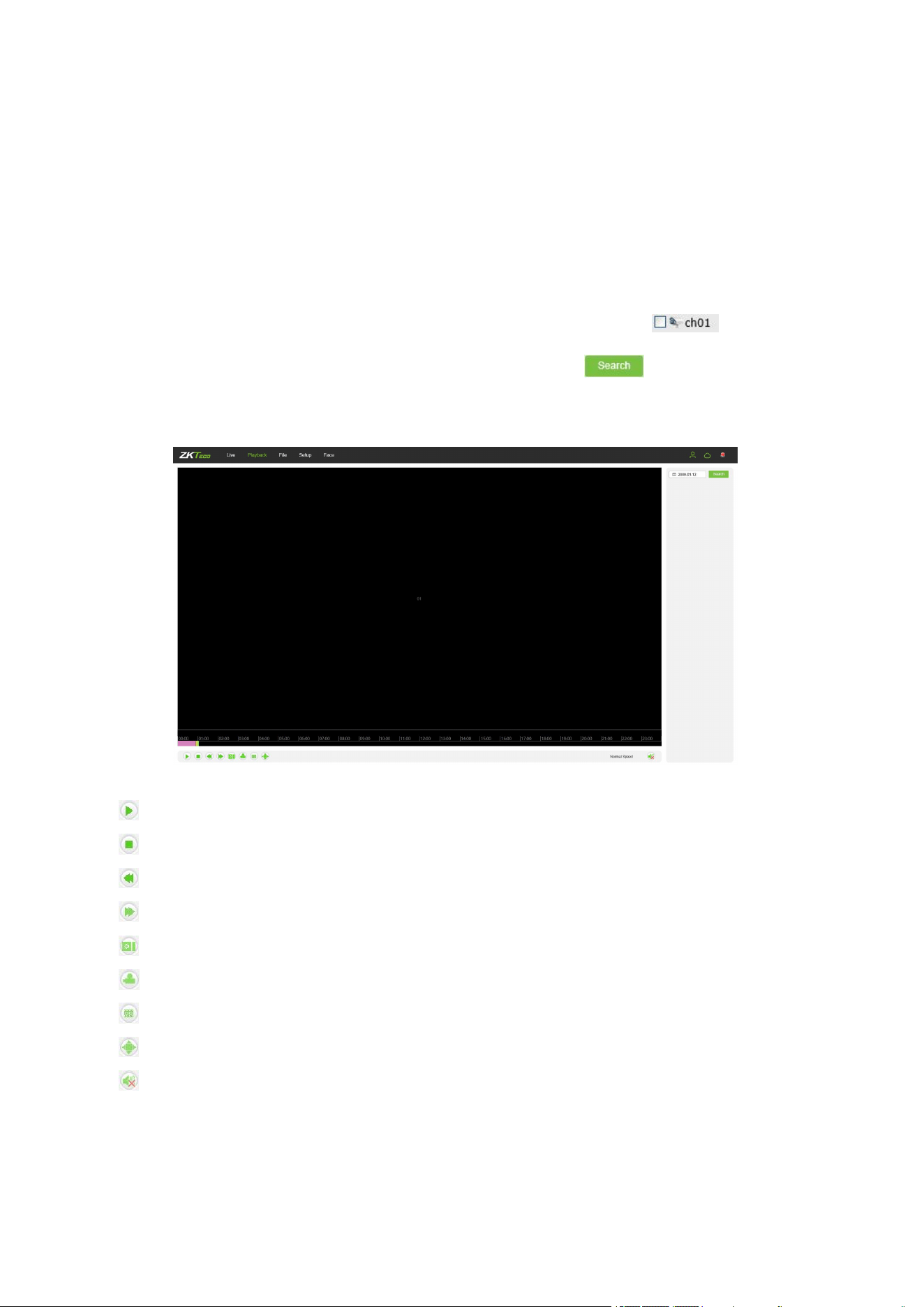
Click on “Playback” to access the playback interface; click on the icon , select the
date and time of videos to be retrieved, then click on the icon , the system will then
search for the corresponding videos automatically, as shown in the following figure:
Start: Start the playback.
Stop: Stop the playback.
Slow: Slow down the playback speed (1/2, 1/4, 1/8, 1/16 times).
Fast: Speed up the playback speed (2, 4, 8, 16 times).
Snapshot: Take snapshots in a playback channel.
Backup: Back up videos in a playback channel.
Frame Play: Play by single frame.
Full Screen: Play videos back in full screen.
Voice: Adjust the volume of playback audio.
Double-click on the slider to play the video, or you may click the “Start” button to start playing the
videos back.
13
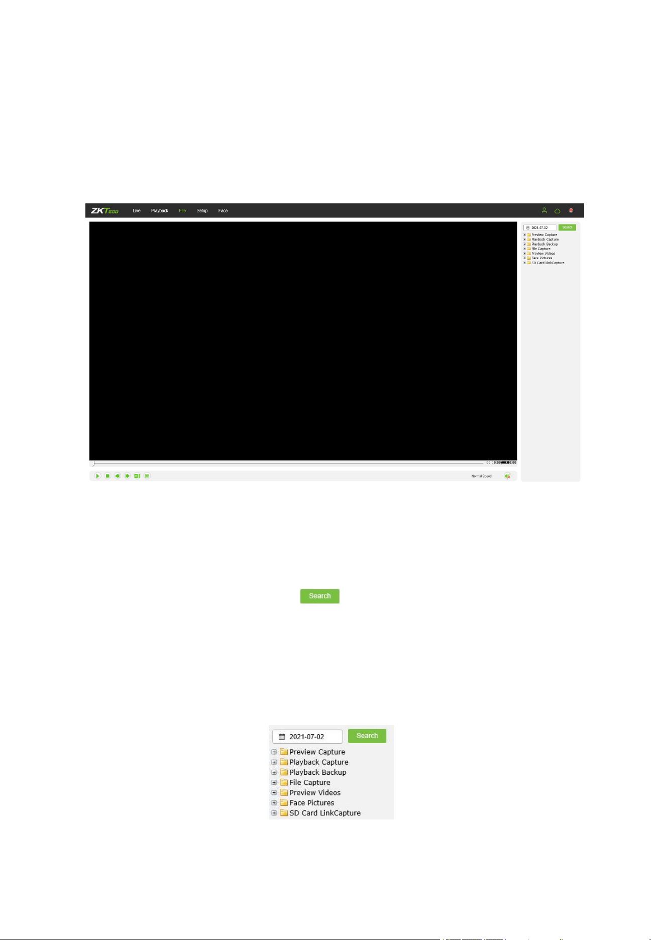
4 File Management
Note: You have to insert a TF card first to access the full function display interface;
otherwise, the system will only show you the simplified version.
·Face Picture: Capture image after face verification successfully
4.1 Search
Input a concrete time, and click on the button, the lower part of th e sc r e e n wi l l
display the searched images and videos. You may double-click on the searched results to
access files you need.
Note: You may modify th e s t orag e path s of th e sel e c t e d videos or images. A short
description will be given below. For more details, please go to Setup → Local Settings.

14
4.2 Preview Capture
To review captured images from video preview; you may search for and double click to obtain
images you need.
4.3 Playback Capture
To review captured images from video playback; you may search for and double click to obtain images
you need.
4.4 Playback Backup
To retrieve video files; you may search for and view videos files.
4.5 File Capture
To review captured images from the file management interface; you may search for and double
click to obtain the images you need.
4.6 Preview Videos
To preview videos recorded; you may search for and double click to access the videos you
need.
4.7 SD Card Link Capture
To review snapshots from a SD card; you may search for and double click to access the videos
you need.
4.8 Backup Video Play
Start: Click on the button to play a selected backup video.
Stop: Click on the button to stop playing the video.
Slow: Click on the button to slowly play the video back.

15
Fast: Click on the button to fast-forward the video.
Frame: Click on the button to play the video by frame.
Capture: Click on the button to take a snapshot of the display during playback.
Voice: Clik on the button to turn sound on or off during playback.
16
5 Parameter
Note: You have to insert a TF card first to access the full function display interface;
otherwise, the system will only show you the simplified version.
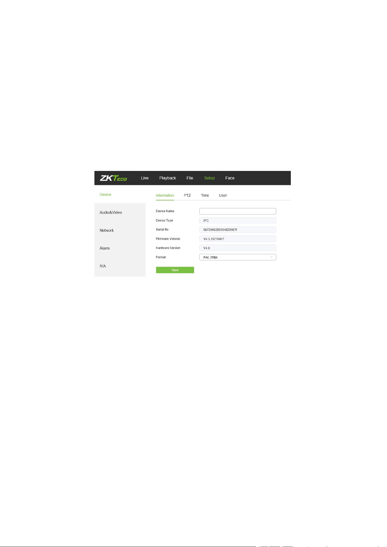
5.1 Device Information
Below is the Device Information interface of the IP camera:
Device Name: Edit the camera name.
Device Type: Display the device type.
Serial No: Display the product serial number.
Firmware Version: Display information about the firmware version.
Hardware Version: Display the version number of the hardware.
Format: Select between PAL and NTSC image scanning system.
After completing all parameters settings, click on “Save”, then the settings will take effect
immediately.
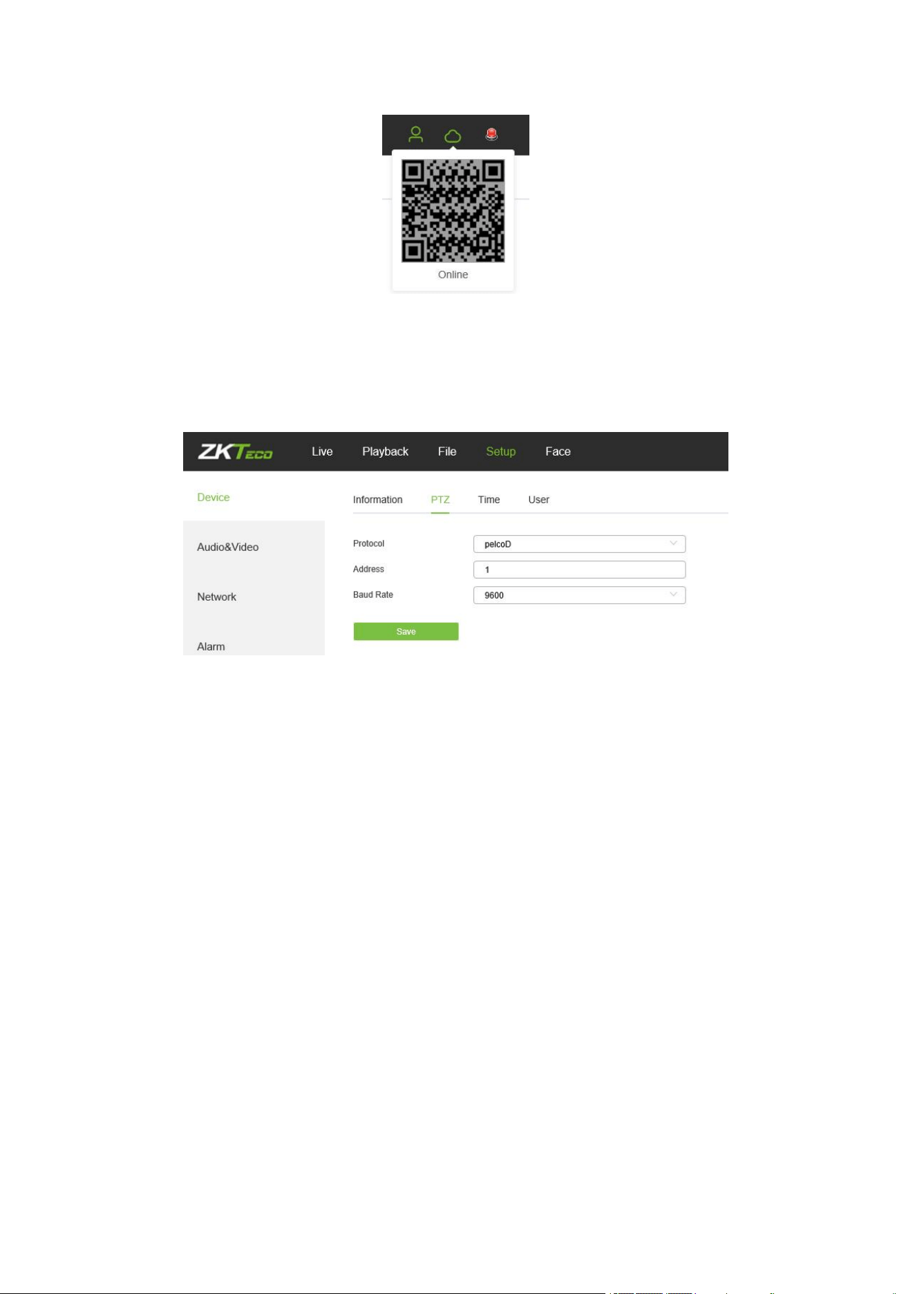
5.2 QR Code
IPC with P2P function can be remotely connected to the mobile APP by scanning the QR Code
on this page.
17
5.3 PTZ Settings
Below is the PTZ Settings interface of the IP camera:
Protocol: multiple protocols available.
Address: 0-255 address codes available.
Baud Rate: diverse baud available
Operation Method: Connect the IP high speed dome at the A/B port; set a protocol and
baud; then control the high-speed dome on the IPC preview interface.
After completing all parameters settings, click on “Save”, then the settings will take effect
immediately.
5.4 Time Settings
Below is the Time Settings interface of the IP camera:
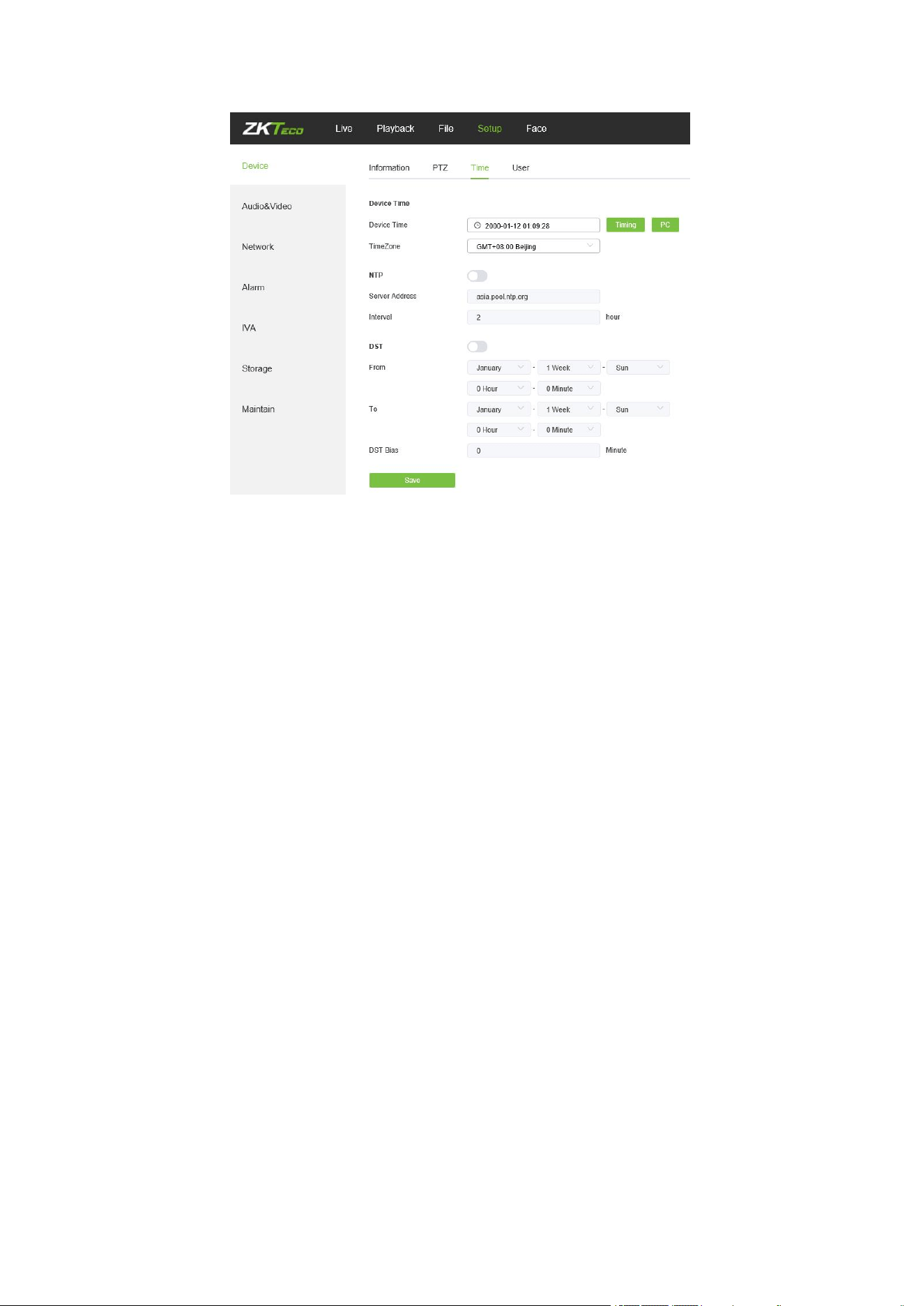
18
Device Time: Set and display the current time of the camera.
Time Zone: Different time zones are available.
Enable NTP: Click to enable or disable NTP.
Server Address: Input the IP address of the NTP server.
Interval: Input the interval of time.
After completing all parameters settings, click on “Save”, then the settings will take effect
immediately.
Enable DST:
Daylight saving time
DSTBias:
the length of the additional offset after starting daylight saving time (0-720 points)
5.5 Audio Settings
Below is the Audio Settings interface of the IP camera:

19
Audio Source: Select the audio input mode between LineIn and MicIn.
Input Volume: Set the input volume which ranges from 0 to 100; the default settings is 50.
Output Volume: Set the output volume which ranges from 0 to 100; the default settings is
50.
After completing all parameters settings, click on “Save”, then the settings will take effect
immediately.
5.6 Display Settings
Below is the Display Settings interface of the IP camera:
Name: Modify the appointed channel name.
Main Stream OSD: Modify the appointed font of the OSD in main stream preview channel.
Sub Stream OSD: Modify the appointed font of the OSD in sub stream preview channel.
20
Three Stream OSD: Modify the appointed font of the OSD in three stream preview
channel.
Multi OSD: Add a multi-user-defined OSD, which you may choose whether to display.
Time Format: Select different time format for the appointed channel.
Date Format: Select different date format for the appointed channel.
Name: Set the location of the title for the appointed channel.
Date Time: Set the location of the date for the appointed channel.
Multi OSD: Set the position of multi OSD.
OSD Color: Set the color of the OSD font.
OSD Font: Select OSD font.
After completing all parameters settings, click on “Save”, then the settings will take effect
immediately.
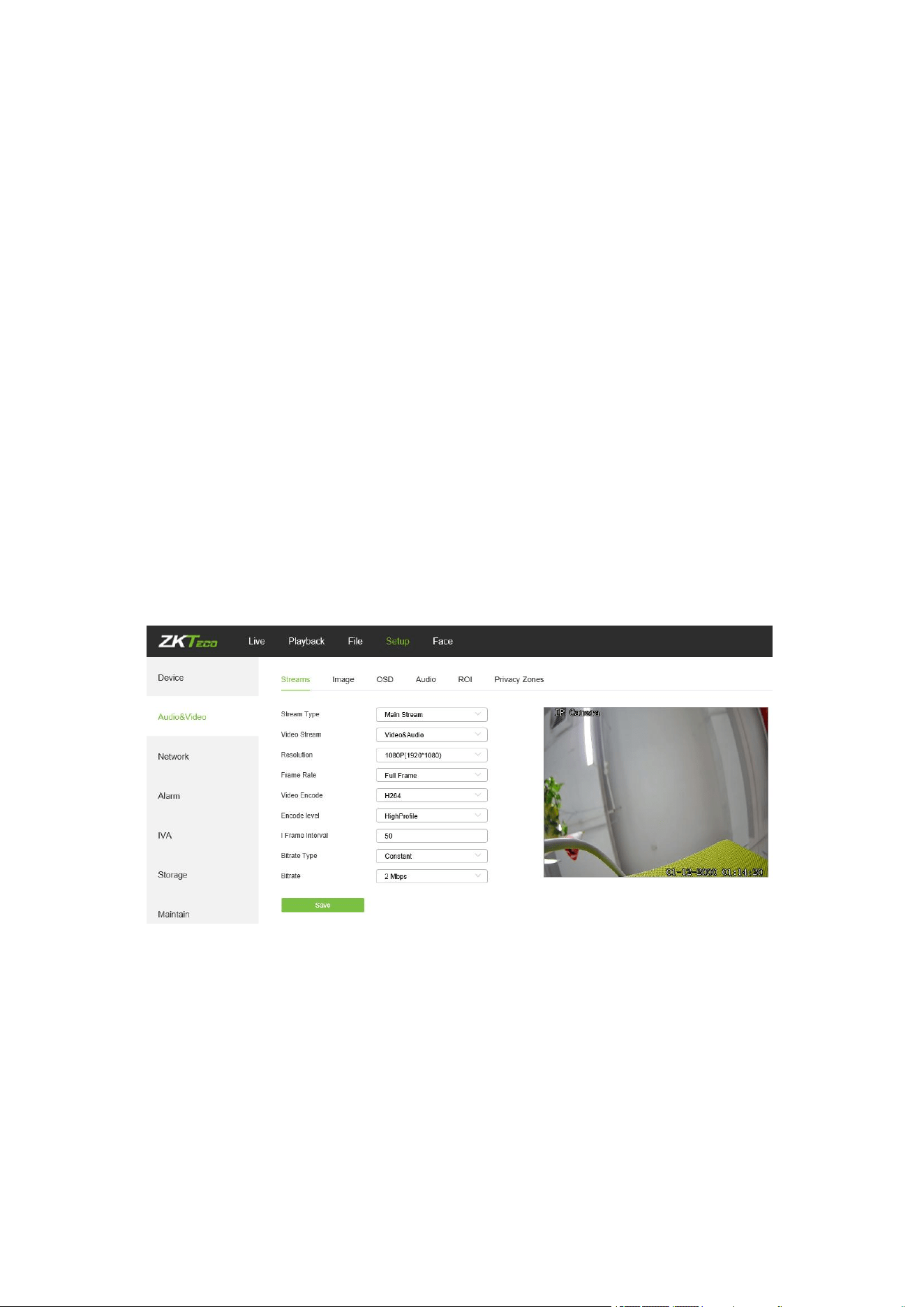
5.7 Streams
Below is the Streams setting interface of the IP camera:
Stream Type: Main stream/ Sub-stream/Third Stream
Video Stream:Video&Audio/ Video
Resolution: Several resolutions available (Note: Based on the defaulted resolution of
different products).
Frame Rate: Select different frame rates from the drop-down list; the default settings is
“Full Frame”.
Video Encode : H.264/ H.265.
21
Encode level: Main profile/ Baseline/ High Profile.
I Frame Interval: Set the interval size of I frame.
Bitrate Type: Constant/ variable.
Bitrate: Set different bitrates for different channels (Note: Based on the defaulted
resolution of different products)
After completing all parameters settings, click on “Save”, then the settings will take effect
immediately.
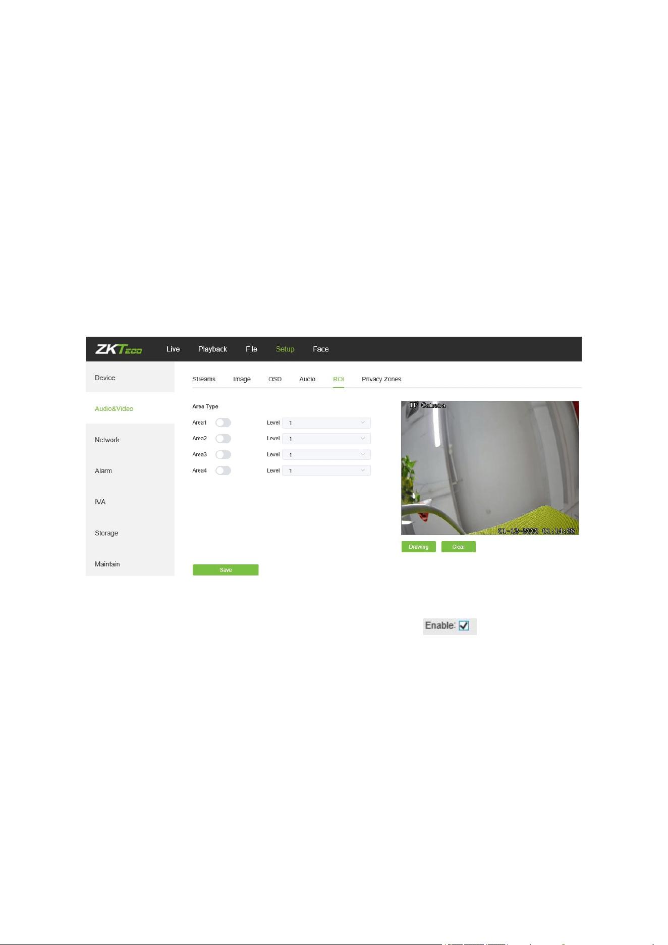
5.8 ROI Settings
Below is the ROI Settings interface of the IP camera:
ROI Settings: On the preview window, hold the left mouse button and drag to set the ROI
area. There are a total of four ROI areas available. Click on to set the
corresponding ROI region coding level; the higher level the coding, the stronger the ROI
region encoding.
After completing all parameters settings, click on “Save”, then the settings will take effect
immediately.
5.9 Image Parameters
Below is the Image Parameters interface of the IP camera:
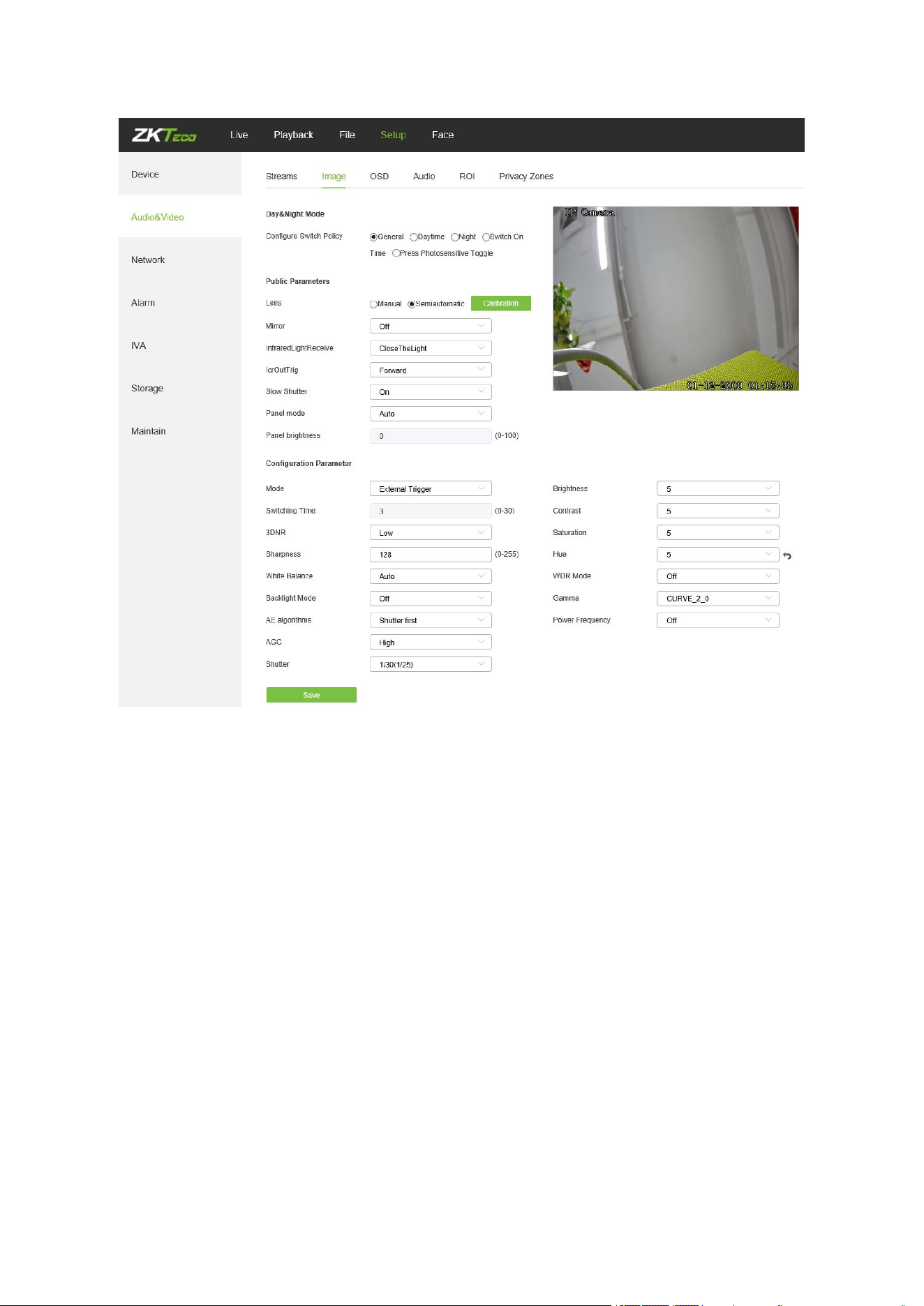
22
Day/Night Mode: Outside Trigger/ Auto/ Color/ Black White. The default setting of
non-infrared IP cameras is “Auto”, and the default setting of infrared IP cameras is “Outside
Trigger”. Users may set the Day/Night mode as needed according to the type of the IP
camera and the actual application environment.
Switching Time: Day & Night switch delay time which ranges from 0-30s; the default
setting is 3s.
Day/Night: ranges from 0 to 255. Users may set the value as needed; the default setting is
20.
Night/Day: ranges from 0 to 255. Users may set the value as needed; the default setting is
35.
Color Mode: Normal/ Bright/ Nature; the default setting is “Normal”
Mirror: Off Horizontal Mirror/ Vertical Mirror/ 180° Rotation/90° Rotation/270° Rotation ;
the default setting is “Off”.

23
WDR Mode: Off/ BLC/ WDR; the default setting is “Off”.
3DNR: Off/ Low/ Mid/ Mid-High/ High; the default setting is “Low”.
Sharpness: ranges from 0 to 255; the default setting is 128.
Defogging: Off/ Low/ Mid/ High; the default setting is “Off”.
Slow Shutter: Off/On; the default setting is “Off”.
White Balance: Users may set the value of white balance. “Auto white balance” is suitable
for normal light environment. Users may adjust the white balance mode from the
drop-down list.
Exposure Control: Auto/ manual; the default setting is “Auto”.
AE algorithms: Shutter first/ gain first; the default setting is “Shutter first”.
AGC: AGC can be set when the camera is automatically exposed. You may select from
Low/ Mid-Low/ Mid/ Mid-High/ High; the default settings is “Mid-High”. The larger the “Auto
Gain” value, the better the sensitivity under low illumination, and the more obvious the
noise will be.
Shutter: You may set manual exposure; the value ranges from 1/25(30) to 1/10000.
Aperture: Depending on the type of IPC lens, the aperture can be divided into manual
aperture and auto aperture (Note: based on the defaulted aperture of different products);
and the lens can be divided into manual focus and vari-focus.
Gamma: A total of four modules: CURVE_1_6, CURVE_1_8, CURVE_2_0, CsURVE_2_2;
the default setting is CURVE_2_0.
Power Frequency: There are three options: off, 50hz, 60hz; the default setting is “off”.
Light board control mode: There are three LED board control modes: off, manual, auto;
the default setting is “auto”.
Off mode: The IR LED will not be turned on.
Manual mode: The brightness of the LED board can be adjusted by manually changing
the related parameters, and the value ranges from 1 to 100. The larger the parameter value,
the brighter the IR LED.
Auto mode: The brightness of the LED board can be adjusted automatically.
Brightness: The brightness of the LED board can be set when the LED board control is
under “Manual” mode. The value ranges from 1 to 100.
After completing all parameters settings, click on “Save”, then the settings will take effect
immediately.
Target Brightness: Adjust the target brightness
24
AE algorithms: Priority selection of adjusting the brightness
AGC:
Improve the image signal to amplification the brightness, which will amplification the image
noise
Shutter:
The exposure time in the snapshot, the longer the exposure time, the brighter the
picture
InfraredLightReceive:
After opening the use of infrared lights to make the picture dark
Model: Brightness adjustment mode of InfraredLight
Brightness:
Manually set the brightness of the InfraredLight
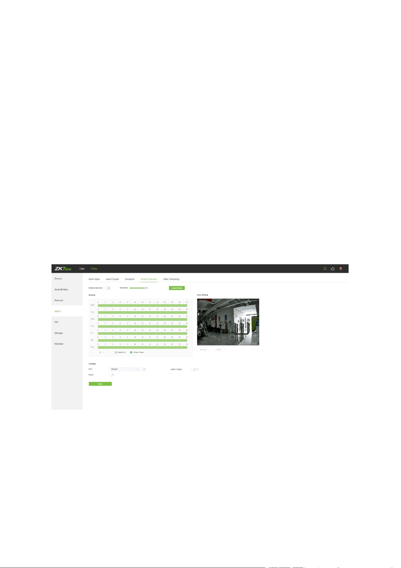
5.10 Motion Detection
Below is the Motion Detection setting interface of the IP camera:
Enable: Select whether to enable the Motion Detection function.
Sensitivity: The higher the sensitivity, the more obvious the motion detective effect will be.
Week: The Detection time can be set from Monday to Sunday.
Arming Schedule: Set up an arming period; you may set up to 8 time periods for a day.
Area Setting: On the “Area Setting" preview interface, left-click and drag the mouse to set
the area to be monitored.
Clear: Click on “Clear” to clear the current controlled areas.
25
Email: Click on “Email”. Once an alarm is triggered, an email will be automatically sent to
the appointed mailbox.
Snap: Click on “Snap”. Once an alarm is triggered, a signal will instantly be sent to the
camera to take a snapshot and store it in the TF card.
Record: Click on “Record”. Once an alarm is triggered, a signal will instantly be sent to the
camera to record a video and store it in the TF card.
Alarm Output: There should be an active alarm device inserted into the IPC alarm output
port. Once an alarm event is triggered, the IPC and alarm device will set off the alarm.
PTZ: Enable or disable PTZ function.
Preset: When motion detection triggers an alarm, the alarm will link with the preset point.
Snap Interval: Set the time intervals for taking snapshots.
Snap Number: Set the number of snapshots taken each time.
After completing all parameters settings, click on “Save”, then the settings will take effect
immediately.
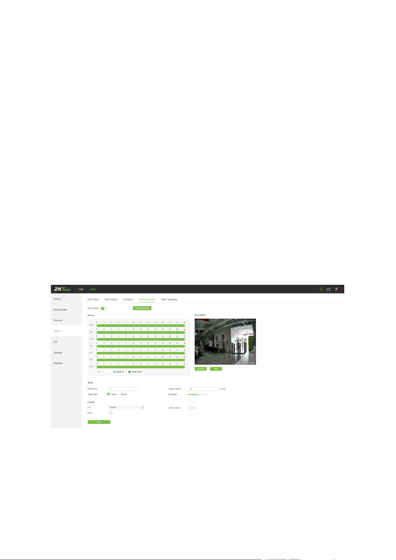
5.10.1Smart Motion
Enable: Select whether to enable the Motion Detection function.
Week: The Detection time can be set from Monday to Sunday.
Arming Schedule: Set up an arming period; you may set up to 8 time periods for a day.
Area Setting: On the “Area Setting" preview interface, left-click and drag the mouse to set
the area to be monitored.
Clear: Click on “Clear” to clear the current controlled areas.

26
Detect Area: Add controlled zones (max. 4).
Object Percent: Sets the size of the object that triggers the alert. If objects smaller than the
preset value, such as mosquitoes and leaves, enter the monitoring area, the alarm will not
be triggered.
Object Type:Set the detection object to be human or vehicle, and an alarm will be triggered
when the object detected in the area is the set value.
Sensitivity: The higher the sensitivity, the more obvious the motion detective effect will be.
Email: Click on “Email”. Once an alarm is triggered, an email will be automatically sent to
the appointed mailbox.
Alarm Output: There should be an active alarm device inserted into the IPC alarm output
port. Once an alarm event is triggered, the IPC and alarm device will set off the alarm.
PTZ: Enable or disable PTZ function.
Preset: When motion detection triggers an alarm, the alarm will link with the preset point.
Snap: Click on “Snap”. Once an alarm is triggered, a signal will instantly be sent to the
camera to take a snapshot and store it in the TF card.
Record: Click on “Record”. Once an alarm is triggered, a signal will instantly be sent to the
camera to record a video and store it in the TF card.
After completing all parameters settings, click on “Save”, then the settings will take effect
immediately.
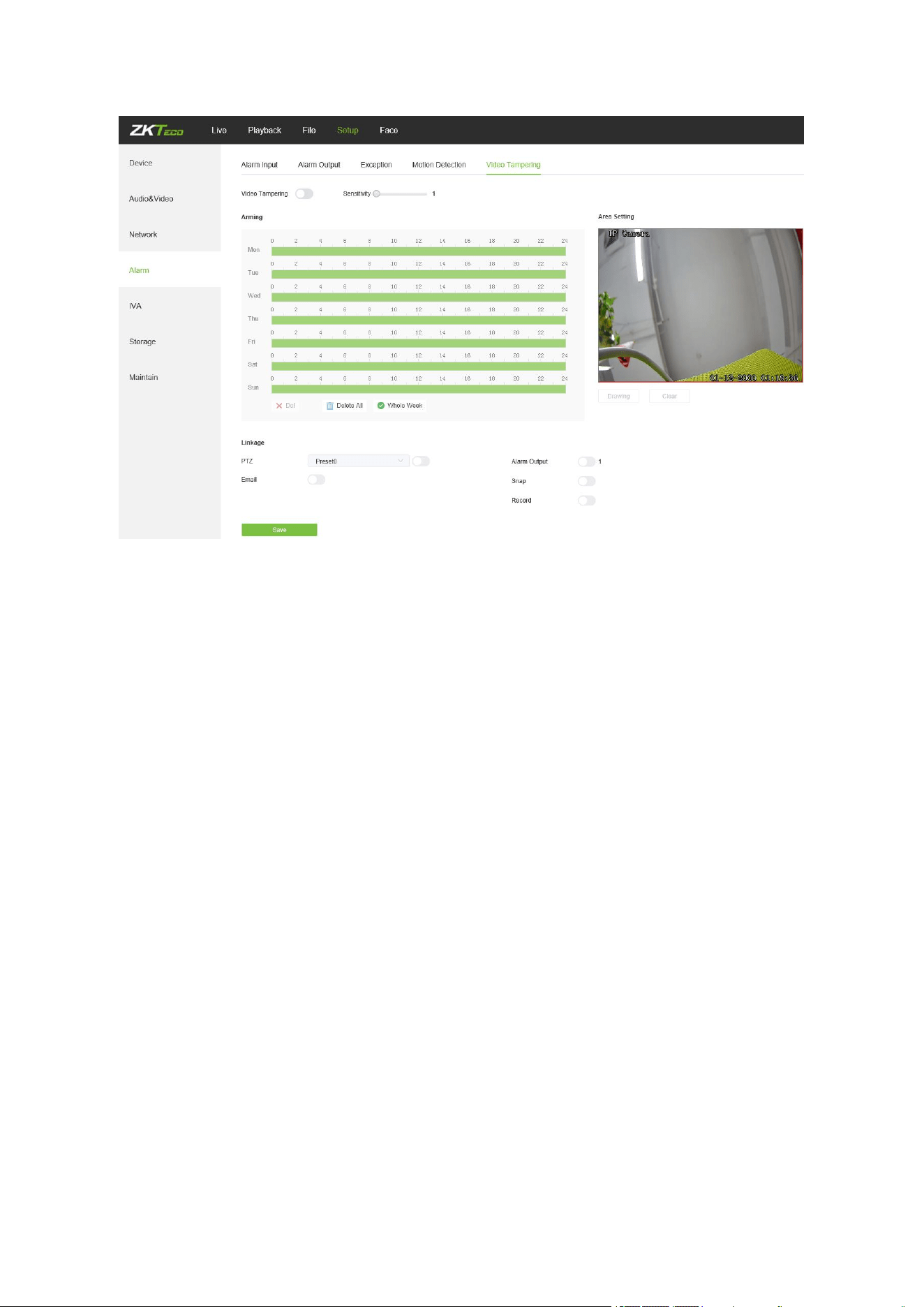
5.11 Video Tampering
Below is the Video Tampering setting interface of the IP camera:
27
Enable: Select whether to enable the video tampering function.
Sensitivity: The higher the sensitivity, the easier to trigger the video tampering alarm.
Week: The protection time can be set from Monday to Sunday.
Arming Schedule: Set up a protection period; you may set up to 8 time periods for a day.
Area Setting: On the “Area Setting" preview interface, left-click and drag the mouse to set
the area to be monitored.
Clear: Click on “Clear” to clear the current controlled areas.
Email: Click on “Email”. Once an alarm is triggered, an email will be automatically sent to
the appointed mailbox.
Snap: Click on “Snap”. Once an alarm is triggered, a signal will instantly be sent to the
camera to take a snapshot and store it in the TF card.
Record: Click on “Record”. Once an alarm is triggered, a signal will instantly be sent to the
camera to record a video and store it in the TF card.
Alarm Output: There should be an active alarm device inserted into the IPC alarm output
port. Once an alarm event is triggered, the IPC and alarm device will set off the alarm.
PTZ: Enable or disable PTZ function.
Preset: When video tampering triggers an alarm, the alarm will link with the preset points.
Snap Interval: Set the time intervals for taking snapshots.
Snap Number: Set the number of snapshots taken each time.
28
After completing all parameters settings, click on “Save”, then the settings will take effect
immediately.
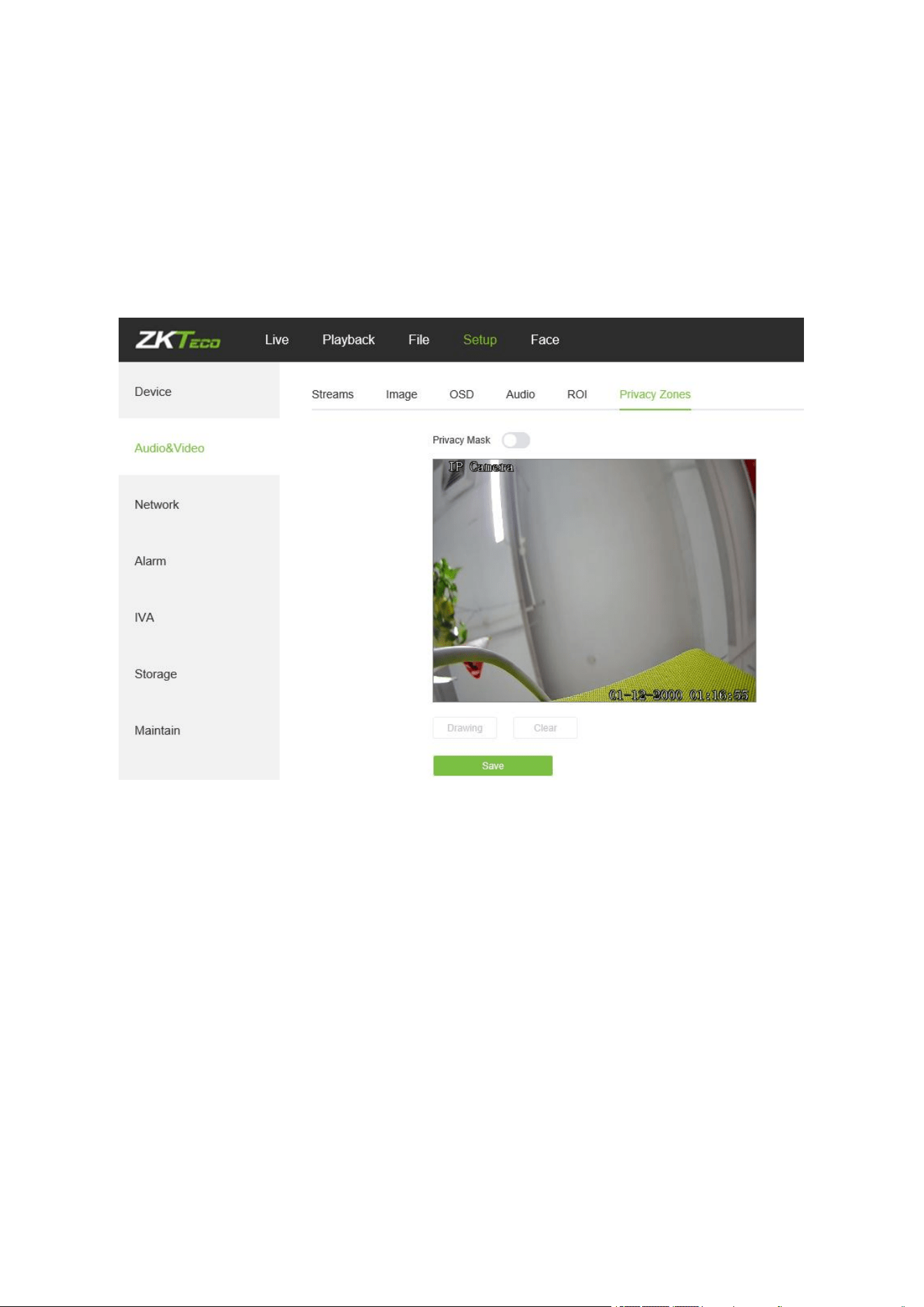
5.12 Privacy Mask
Below is the Privacy Mask setting interface of the IP camera:
Enable: Enable or disable the Privacy Mask feature.
Area Settings: Left-click and drag the mouse on the Area Settings preview interface
drawing to set the mask area.
Clear: Click on “Clear” to delete the current controlled area.
After completing all parameters settings, click on “Save”, then the settings will take effect
immediately.
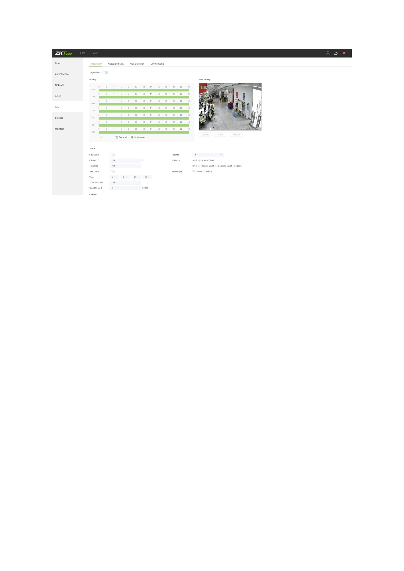
5.13 Target Counting
Below is the Target Count setting interface of the IP camera:
29
Enable: Enable or disable the target counting function.
Arming Schedule: Arm schedule can be set from Monday to Sunday.
Area Setting: Click on “Drawing”, then left-click and drag the mouse button to set the test
line on the Area Settings preview interface. Click on “Stopping” to complete the setting,
then the system will count the number of targets passing through the line.
Clear: Click on “Clear” to delete all the test lines.
Swap AB: Click on “Swap AB" to exchange position between A and B.
Test Line: Add test lines (max. 4 test lines).
Statistics: Set the test lines for targets passing through. There are two statistical methods:
A→B and B→A.A→B will increase the count by default, and B→A can set to increase the
count, decrease the count or ignore
Object Type:Set the detection object to be human or vehicle, and an alarm will be triggered
when the object detected in the area is the set value.
Flow Count: Enable or disable the Flow Counter feature.
Interval: Set the counting time interval. When the counting time exceeds the time interval set,
the flow counter will reset and enter next counting period automatically.
Threshold: Set the upper count limit. When the value exceeds the set value, the system will
automatically trigger the alarm.
Total Count: Enable or disable the Total Counter function.
Time Period: Set the effective time period for the day’s total counter.
Alarm Threshold: Set the upper limit of the total flow on a day. When the value exceeds the
set value, the system will automatically trigger the alarm.
Target Percent: Sets the size of the object that triggers the alert. If objects smaller than the
preset value, such as mosquitoes and leaves, enter the monitoring area, the alarm will not
be triggered.
Email: Click on “Email”. Once an alarm is triggered, an email will be automatically sent to the
appointed mailbox.
Snap: Click on “Snap”. Once an alarm is triggered, a signal will instantly be sent to the
camera to take a snapshot and store it in the TF card.
30
Record: Click on “Record”. Once an alarm is triggered, a signal will instantly be sent to the
camera to record a video and store it in the TF card (for cameras which support TF cards
only).
Alarm Output: There should be an active alarm device inserted into the IPC alarm output
port. Once an alarm event is triggered, the IPC and alarm device will set off the alarm.
PTZ: Enable or disable PTZ function.
Preset: When target counting triggers an alarm, it will link the pre-sets.
Snap Interval: Set the time intervals for taking snapshots.
Snap Number: Set the number of snapshots taken each time.
After completing all parameters settings, click on “Save”, then the settings will take effect
immediately.
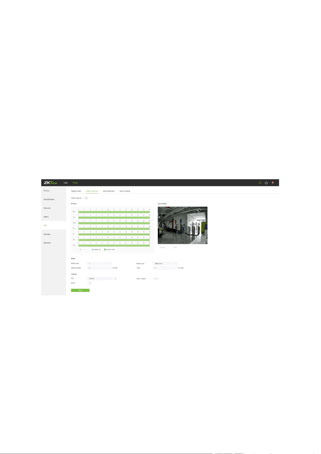
5.14 Object Left / Lost
Below is the Object Left/Lost setting interface of the IP camera:
Enable: Enable or disable the object detection function.
Arming Schedule: Arming schedule can be set from Monday to Sunday.
Area Setting: Click on “Drawing”, then left-click and drag the mouse button to set the detect
zone on the Area Settings preview interface. Click on” Stopping” to complete the setting,
then the system will detect, and monitor objects appeared in the selected area.
Clear: Click on “Clear” to delete all zones.
Detect Area: Add controlled zones (max. 4).
Detect Type: Set the object detection type. There are three detection types, all of them are
able to trigger the alarm. “Item lost” represents that the camera will trigger the alarm once it
detects that an item originally in the monitored area is missing; “Item left” represents that
the camera will trigger the alarm once it detects a new item in the detection area; “Item lost
31
or left” represents that the camera will trigger the alarm once it detects that an item is
missing and/or a new item in the controlled area.
Object Percent: Sets the size of the object that triggers the alert. If objects smaller than the
preset value, such as mosquitoes and leaves, enter the monitoring area, the alarm will not
be triggered.
Detect Time: Set the upper limit of item lost and item left. When it exceeds the set value, the
system will trigger the alarm automatically
Email: Click on “Email”. Once an alarm is triggered, an email will be automatically sent to the
appointed mailbox.
Snap: Click on “Snap”. Once an alarm is triggered, a signal will instantly be sent to the
camera to take a snapshot and store it in the TF card.
Record: Click on “Record”. Once an alarm is triggered, a signal will instantly be sent to the
camera to record a video and store it in the TF card. (Only effect on camera which supports
TF Card)
Alarm Output: There should be an active alarm device inserted into the IPC alarm output
port. Once an alarm event is triggered, the IPC and alarm device will set off the alarm.
PTZ: Enable or disable PTZ function.
Preset: When object detection triggers an alarm, it will link with the preset points.
Snap Interval: Set the time intervals for taking snapshots.
Snap Number: Set the number of snapshots taken each time.
After completing all parameters settings, click on “Save”, then the settings will take effect
immediately.
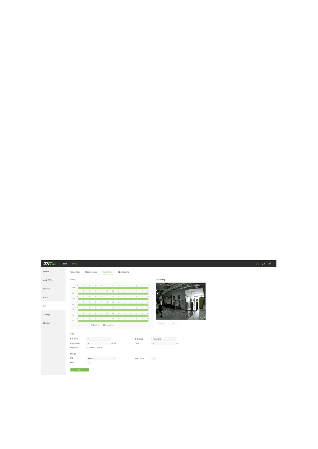
5.15 Area Detection (Intrusion Detection)
Below is the Area Detection setting interface of the IP camera:
Enable: Enable or disable the area detection function.
Arming Schedule: Arming schedule can be set from Monday to Sunday.

32
Area Setting: Click on “Drawing”, then left-click and drag the mouse button to set the detect
zone on the area settings preview interface. Click on “Stopping”to complete the setting,
then the system will detect, and monitor objects appeared in the selected area.
Clear: Click on “Clear” to delete all zones.
Detect Area: Add controlled zones (max. 4).
Detect Type: Set the target detect type. There are four detection types, all of them will
trigger the alarm. “Target enter” represents that the camera will trigger the alarm once it
detects that a target enters the monitored zone; “Target leave” represents that the camera
will trigger the alarm once it detects that a target leave the zone; “Target enter or leave”
represents that the camera will trigger the alarm once it detects that a target enters and/or
leave the zone. The last type is that the camera will trigger the alarm once it finds that the
time that a target staying in the controlled area exceeds the upper limit of the set and
allowed duration.
Object Percent: Sets the size of the object that triggers the alert. If objects smaller than the
preset value, such as mosquitoes and leaves, enter the monitoring area, the alarm will not
be triggered.
Object Type:Set the detection object to be human or vehicle, and an alarm will be triggered
when the object detected in the area is the set value.
Detect Time: When the staying time of the set target in the monitored area exceeds the set
duration, the system will trigger the alarm.
Email: Click on “Email”. Once an alarm is triggered, an email will be automatically sent to the
appointed mailbox.
Snap: Click on “Snap”. Once an alarm is triggered, a signal will instantly be sent to the
camera to take a snapshot and store it in the TF card.
Record: Click on “Record”. Once an alarm is triggered, a signal will instantly be sent to the
camera to record a video and store it in the TF card (for cameras which support TF cards
only).
Alarm Output: There should be an active alarm device inserted into the IPC alarm output
port. Once an alarm event is triggered, the IPC and alarm device will set off the alarm.
PTZ: Enable or disable PTZ function.
Snap Interval: Set the time intervals for taking snapshots.
Snap Number: Set the number of snapshots taken each time.
After completing all parameters settings, click on “Save”, then the settings will take effect
immediately.
5.16 Line Crossing (Tripwire)
Below is the Line Crossing setting interface of the IP camera:
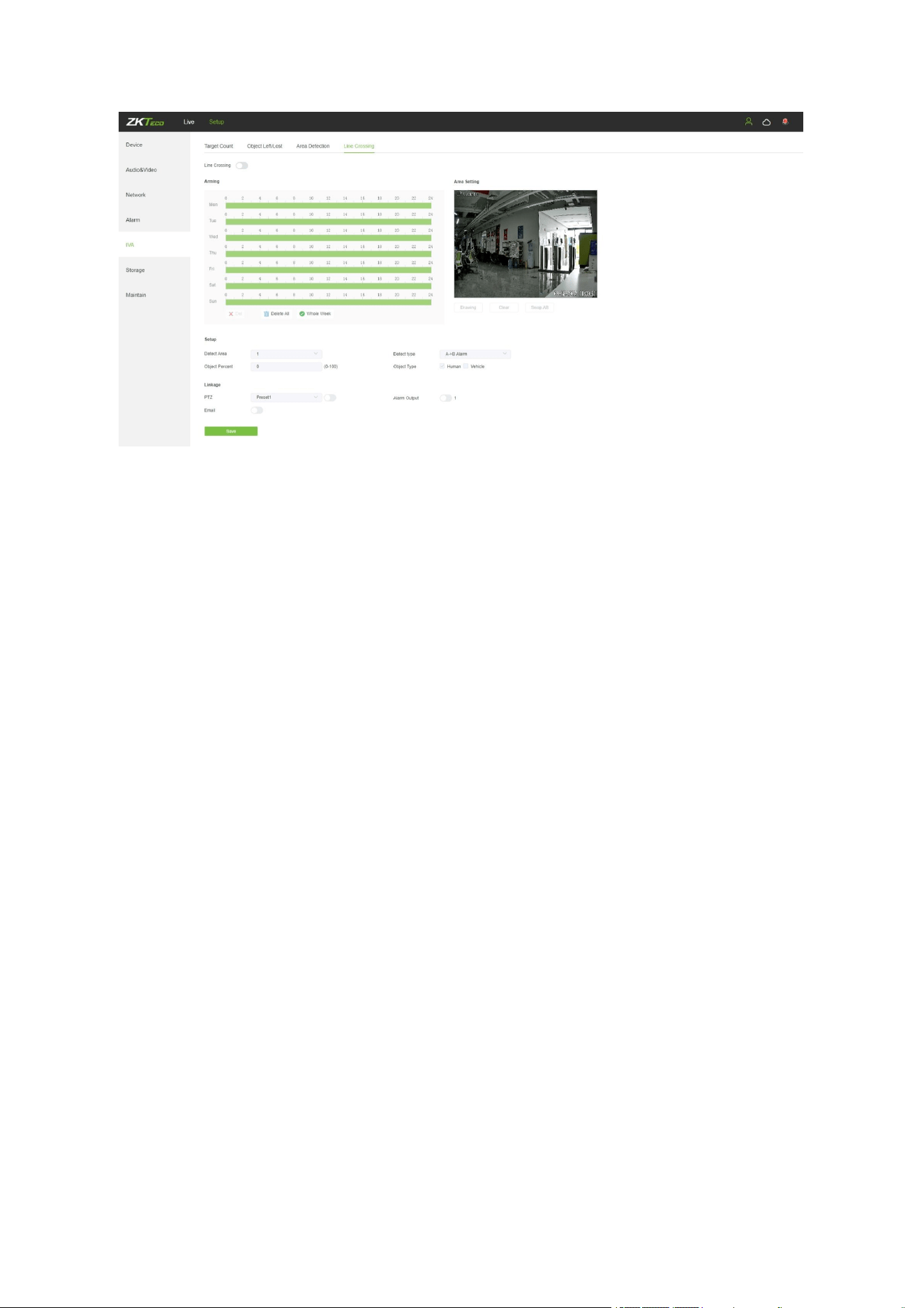
33
Enable: Enable or disable the virtual guard function.
Arming Schedule: Arm schedule can be set from Monday to Sunday.
Area Setting: Click on “Drawing”, then left-click and drag the mouse to set guard lines on the
area settings preview interface. Click on “Stopping” to complete the setting. When a target
passes through the guard line, the system will trigger the alarm.
Clear: Click on “Clear” to delete all zones.
Swap AB: Click on “Swap AB" to swap the positions of A/B ports.
Detect Area: To add new guard lines (max. 4 guard lines).
Detect Type: Set the guard lines to trigger the alarm. “A→B” refers to targets passing
through the guard lines from area A to area B will trigger the alarm. “A←→B” refers to
targets passing through the guard lines either from area A to area B or from area B to area
A will trigger the alarm.
Object Type:Set the detection object to be human or vehicle, and an alarm will be triggered
when the object detected in the area is the set value.
Object Percent: Sets the size of the object that triggers the alert. If objects smaller than the
preset value, such as mosquitoes and leaves, enter the monitoring area, the alarm will not
be triggered.
Email: Click on “Email”. Once an alarm is triggered, an email will be automatically sent to the
appointed mailbox.
Record: Click on “Record”. Once an alarm is triggered, a signal will instantly be sent to the
camera to record a video and store it in the TF card.
Alarm Output: There should be an active alarm device inserted into the IPC alarm output
port. Once an alarm event is triggered, the IPC and alarm device will set off the alarm.
PTZ: Enable or disable PTZ function.
Snap Interval: Set the time intervals for taking snapshots.
Snap Number: Set the number of snapshots taken each time.
After completing all parameters settings, click on “Save”, then the settings will take effect
immediately.
34
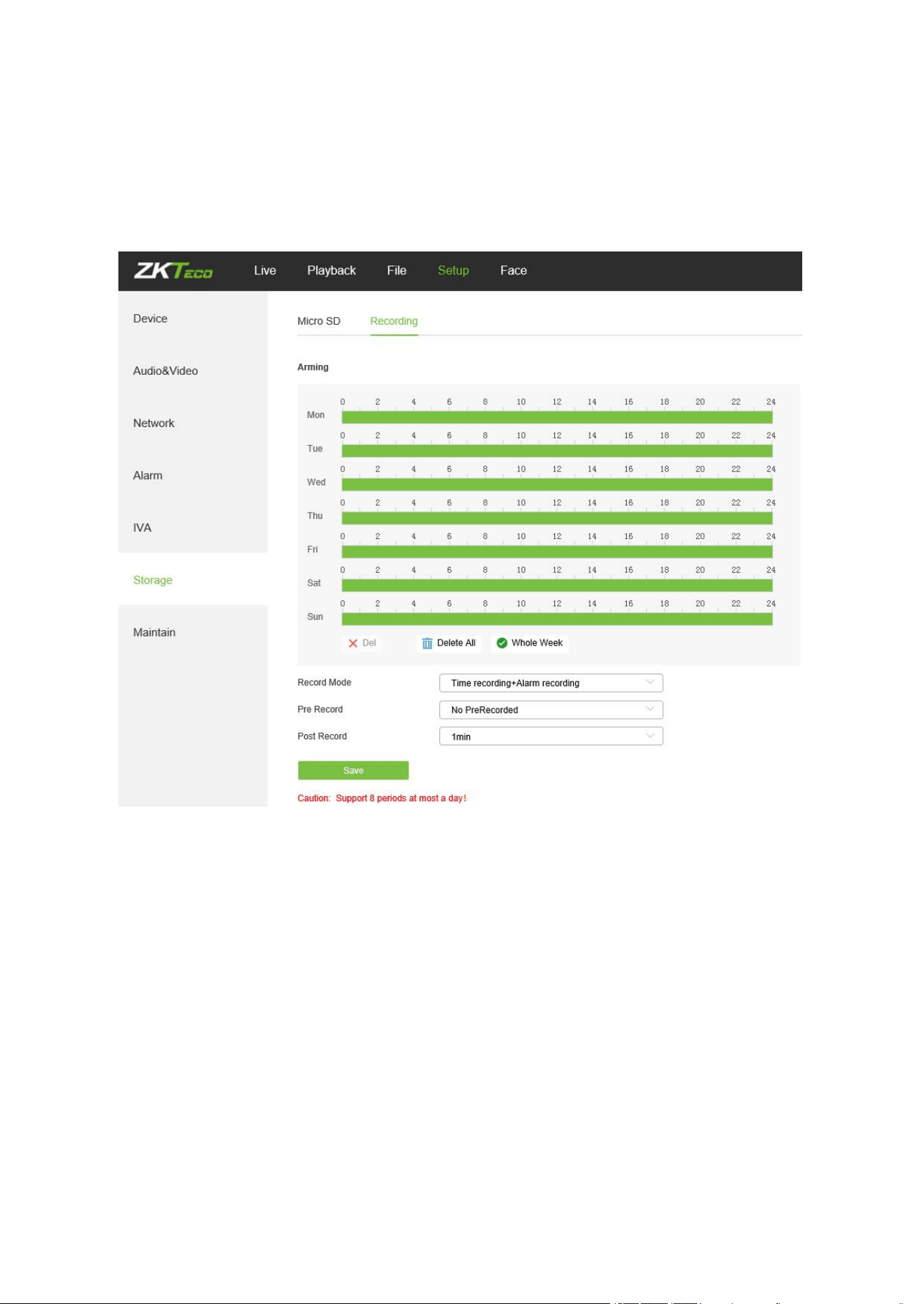
5.17 Video Plan
Only displayed on TF Card supported camera.
Below is the Video Plan setting interface of the IP camera:
Video Mode: Select a video mode. There are four modes available: Time recording +
Alarm recording, Time recording, Alarm recording, No video.
Week: Set the recording time from Monday to Sunday.
Pre Record: Set pre-recording time.
Post Record: Set the recording delay time.
Video Edge IP Address: Enter the IP address of NVR or the server.
After completing all parameters settings, click on “Save”, then the settings will take effect
immediately.
35
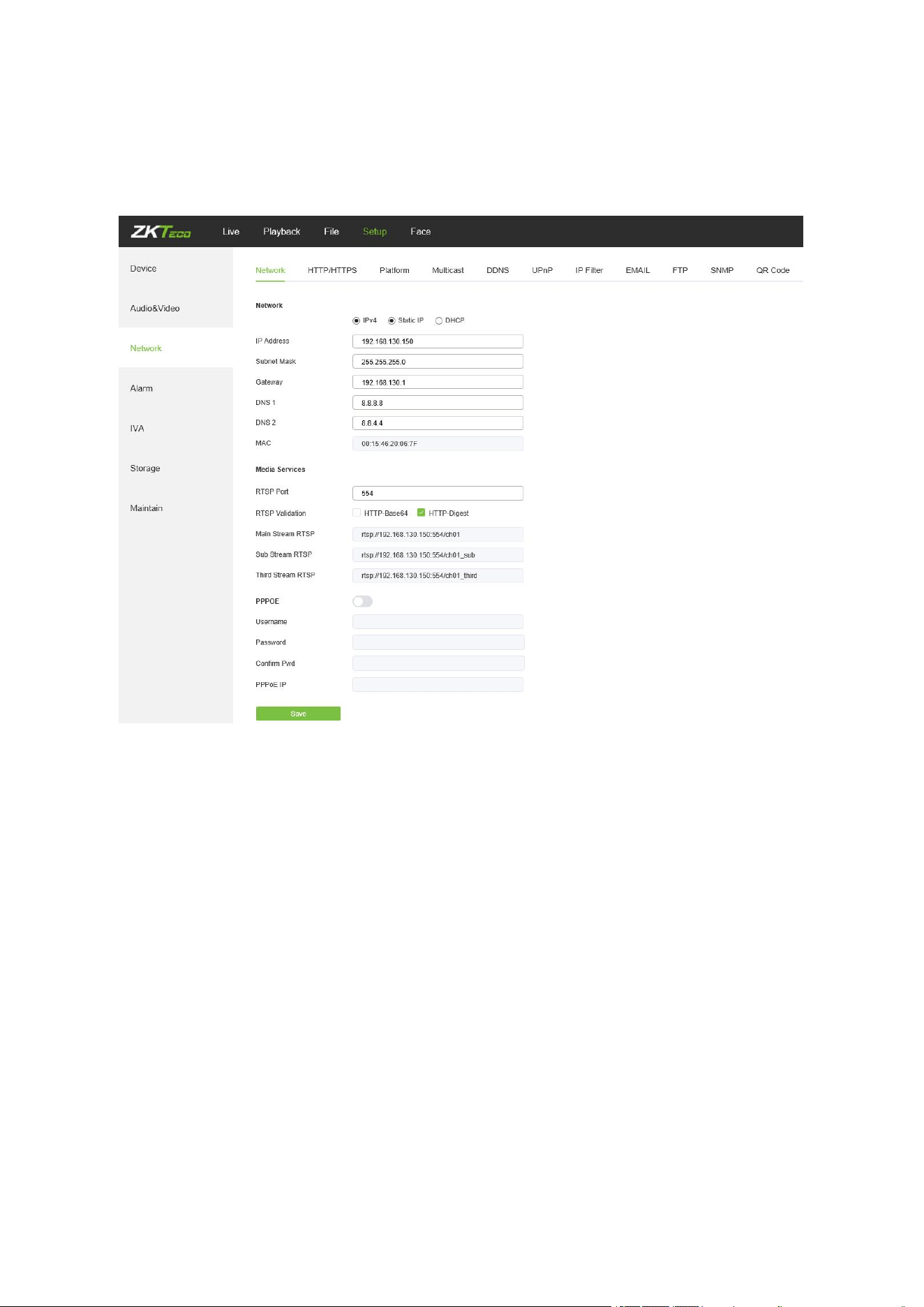
5.18 Network Settings
Below is the Network Settings interface of the IP camera:
IPV4: IP protocol version No. is 4.
Static IP: The device IP address is permanent.
DHCP: Enable DHCP, then the IP camera will obtain the IP address from the router
automatically.
IP Address: Input the corresponding numbers to change the IP address.
Subnet Mask: Input the corresponding IP subnet mask.
Gateway: Input the corresponding gateway address.
DNS 1: IP address of the DNS server.
DNS 2: Another IP address of the DNS server.
RTSP Port: Access the device which needs to map RTSP with a domain name; the default
port is 554.
RTSP Validation: Choose a RTSP verification mode from Http-Base64, Http-Digest. After
choosing and activating the corresponding RTSP verification mode, during playing RTSP
real-time stream, RTSP validation operations need the user name and password for
36
verification.
RTMP Port: Domain name, which is used to access the device which needs to map RTMP;
the default port is 1935.
Username:
PPPOE user name
Passwords: PPPOE password
Confirm Pwd:
Confirm password: Enter the password repeatedly
PPPOE IP: IP setting of PPPOE
After completing all parameters settings, click on “Save”, then the settings will take effect
immediately.
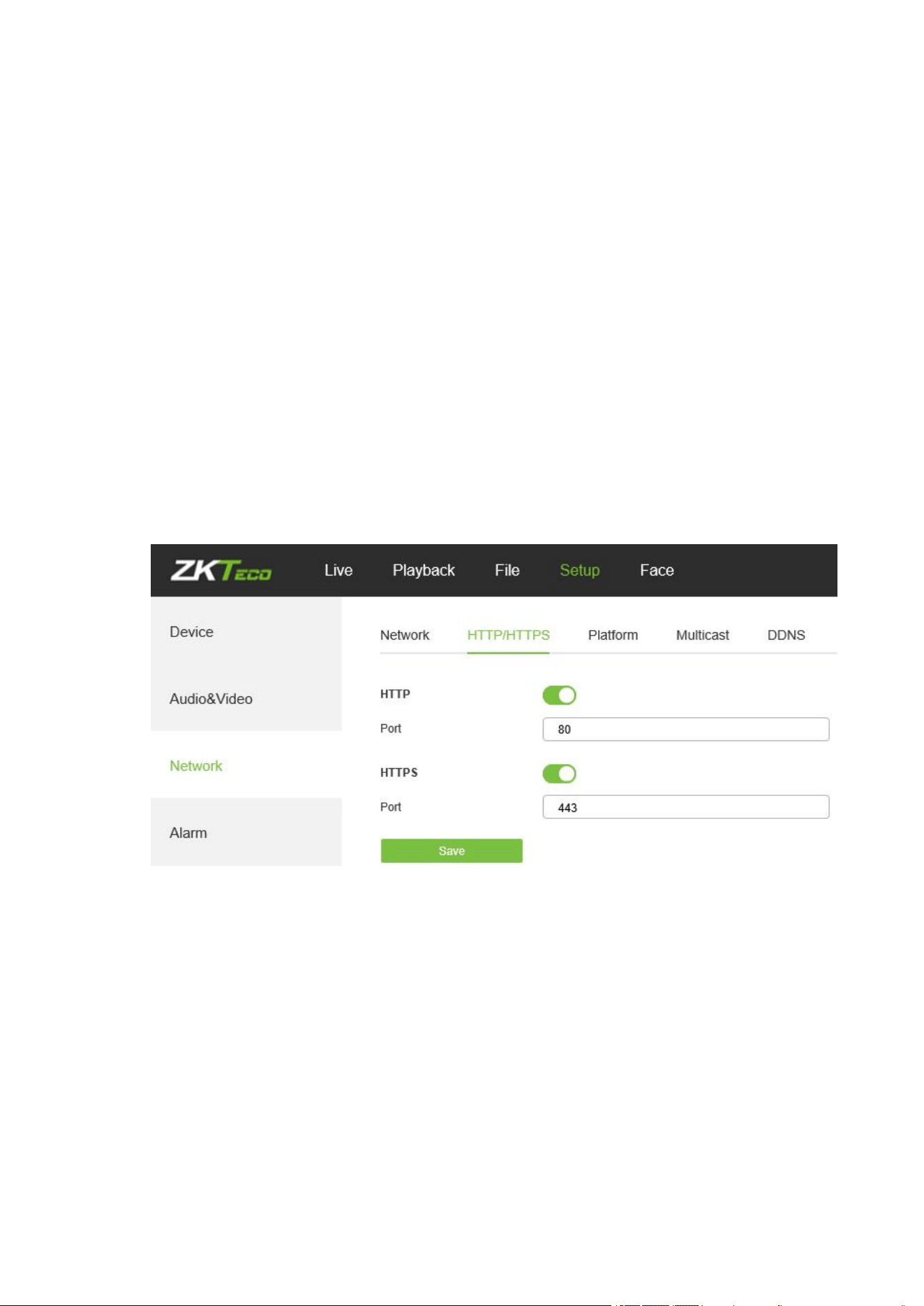
5.19 HTTP/HTTPS
In the HTTP/HTTPS setting interface, users can make PC log in normally via HTTP/HTTPs.
Enable: Enable or disable HTTP/HTTPS function.
HTTP port: Port range is 1~65524. The default value is 80.
HTTPs Port: HTTPs communication port, range is 1~65534, default is 443.
5.20 Management Platform
Below is the Management Platform interface of the IP camera:
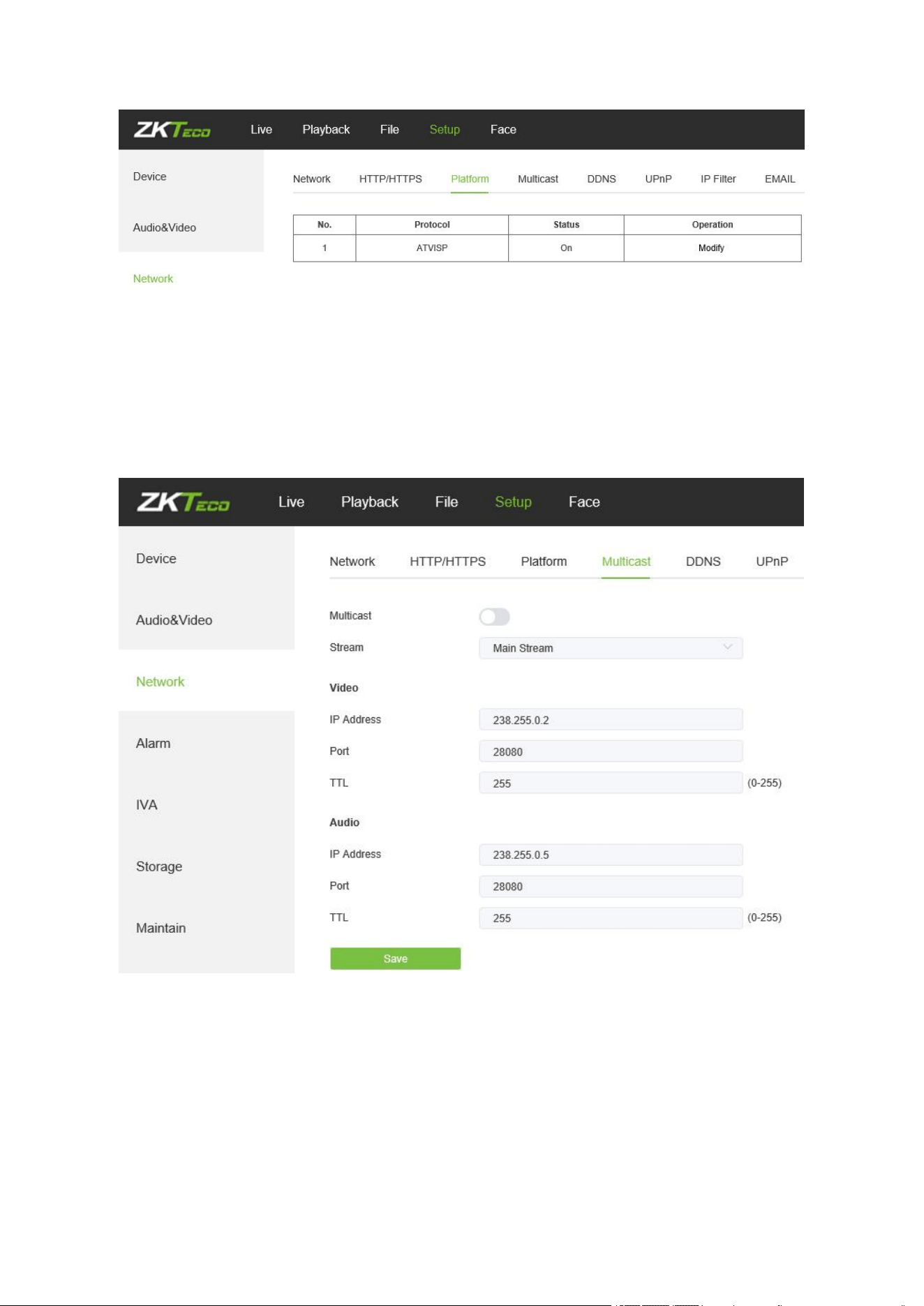
37
Users may activate or deactivate a protocol and modify the protocol information here.
5.21 Multicast Configuration
Below is the Multicast Config interface of the IP camera:
Multicast configuration is disabled by default. By clicking on “Enable Multicast", users may set
the IP address, port and TTL of main stream video/audio, sub stream video/audio.
5.22 DDNS Settings
DDNS is implemented through a dynamic domain resolution server. It requires a fixed IP
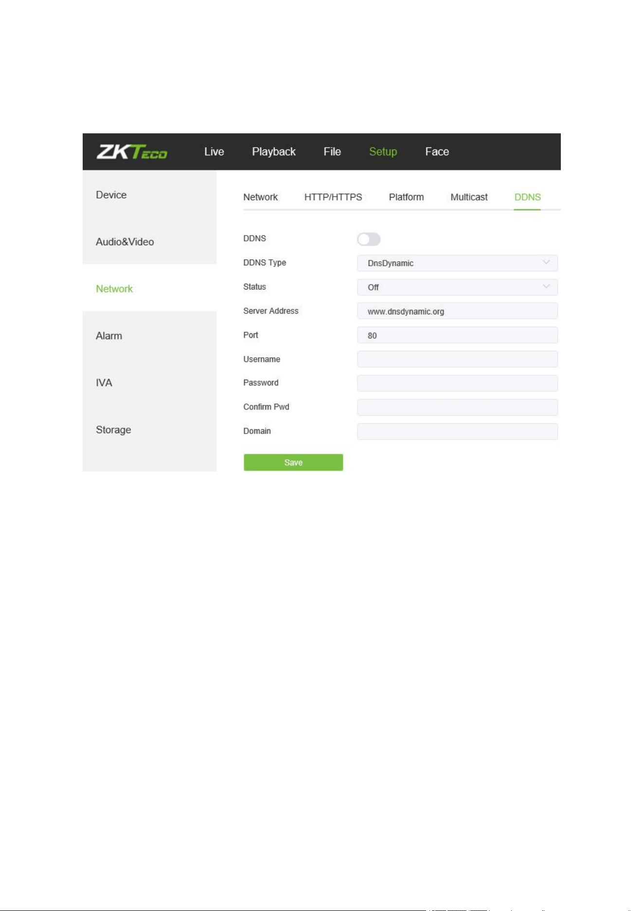
38
address on of the device running on the server. The DDNS setting interface of the IP camera is
as shown below:
Enable DDNS: Enable or disable DDNS function.
DDNS Type: Select a DDNS server type from Dyndns, PeanutHull, NO-IP, 3322, and
DnsDynamic.
Status: Turn on or off the DDNS.
Server Address: Input a server name, for example, dynupdate.no-ip.com.
Port: Input a port. The default port is 80.
User Name: Input a user name.
Password: Input a password.
Confirm Pwd: Input the password again to confirm.
Domain: Input the second domain.
After completing the parameters settings, click on “Save”, then the settings will take effect
immediately.
39
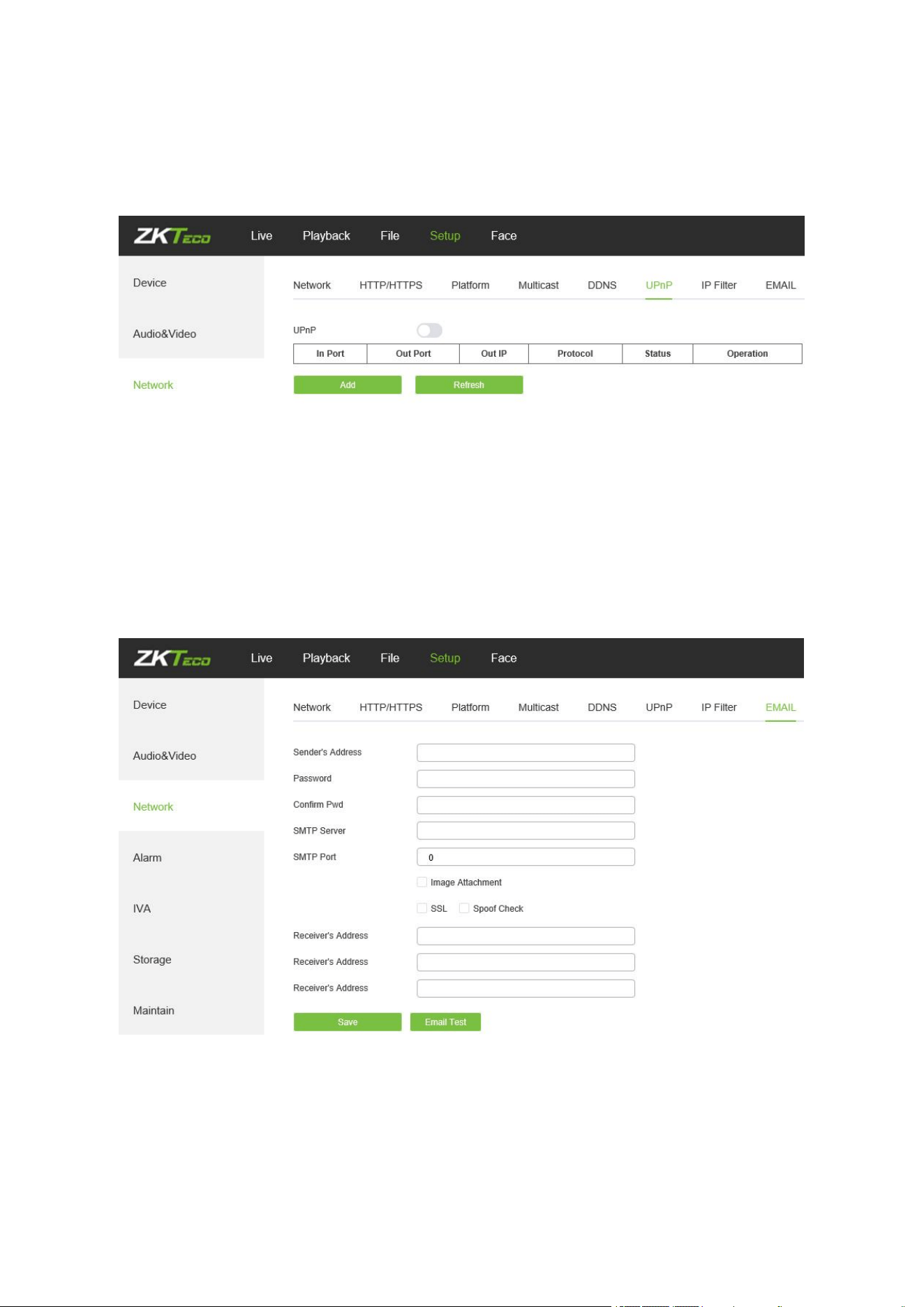
5.23 UPnP Settings
Below is the UPnP Settings interface of the IP camera:
Enable UPnP: Activate or deactivate the UPnP function. When it is enabled, the device
can port mapping through the router.
Add: User may add TCP/UDP protocol, set internal and external port.
5.24 Email Settings
Below is the Email Settings interface of the IP camera:
Sender Address: Input the email address of the sender.
Password: Input the password of the outbox.
Confirm Pwd: Input the password again to confirm.
SMTP Server: Input the SMTP server address of the outbox.
40
SMTP Port: Input the SMTP server port of the outbox.
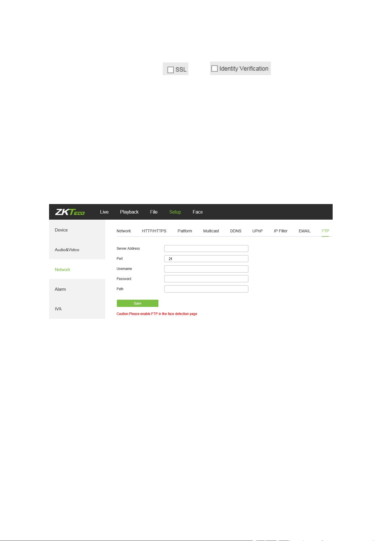
SSL/Identity verification: Tick and to send the email
correctly and safely.
Receiver's Address: Input the address of the inbox, fill in the address of the receiving
email; you may fill in 3 other receivers’ addresses.
After completing all parameters settings, click on “Save”, then the settings will take effect
immediately.
5.25 FTP Settings
Below is the FTP Settings interface of the IP camera:
Server Address: Input the FTP Server address.
Port: Input the FTP server port.
Username: Input the FTP server username.
Password: Input the FPT server password.
Path: Input the file upload path.

41
5.26 SNMP Settings
Below is the SNMP Settings interface of the IP camera:
Enable: Enable or disable SNMP service.
Manager IP: Messages will be sent to this manager IP address.
Send Count: The maximum number of messages to be delivered when an alarm is
triggered. The value ranges from 1 to 5.
Send Interval: Interval between messages sending. The range is 60-250s.
5.27 Alarm Input
Below is the Alarm Input setting interface of the IP camera:
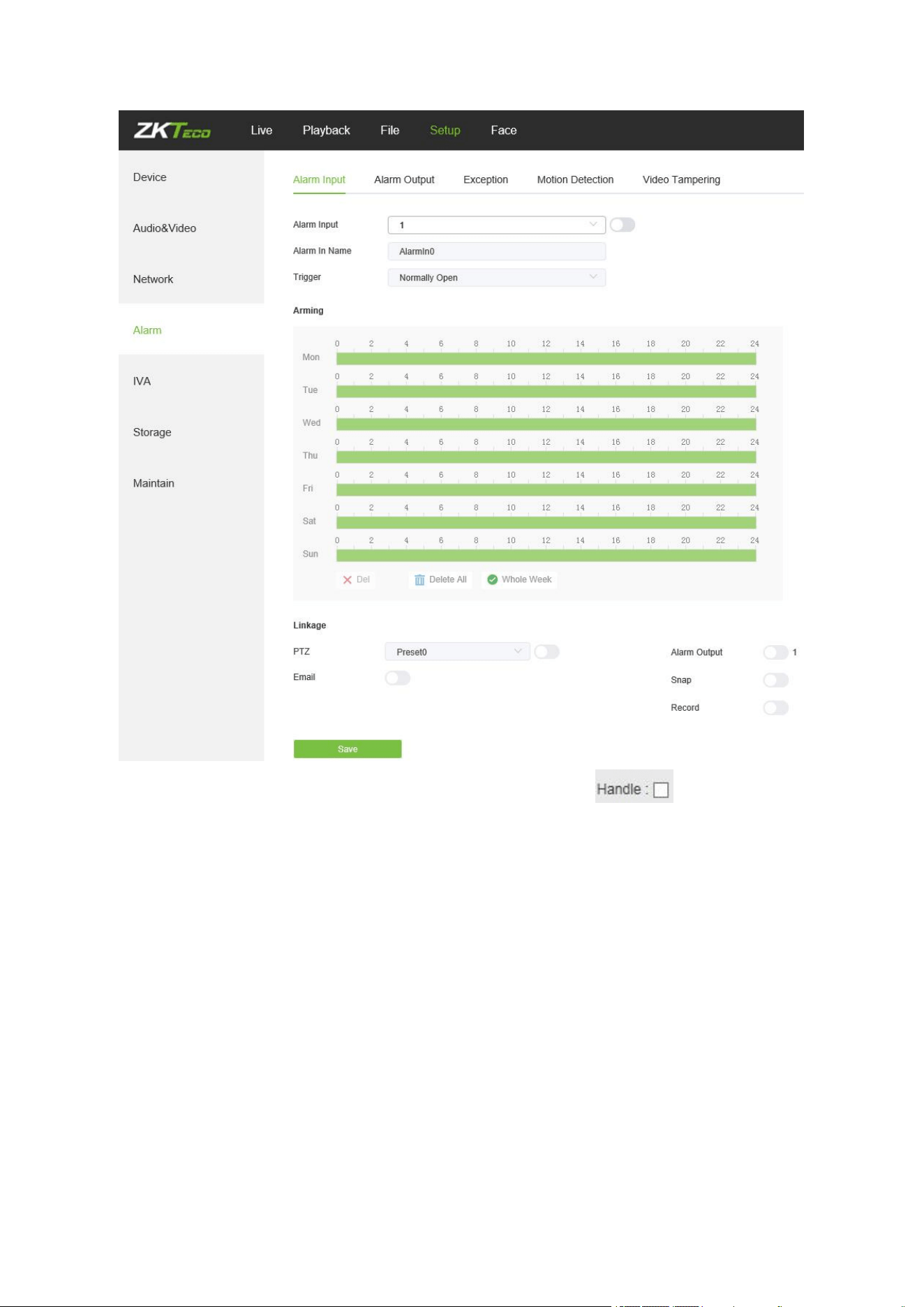
42
Alarm Input: Select the alarm input port, then check the box to implement the
following parameters settings.
Alarm In Name: Input a name of an alarm.
Trigger Level: Select the alarm status: Normally Open/ Normally Close.
Arming Schedule: Arming schedule can be set from Monday to Sunday. You may set up
to 8 schedules for a day.
Email: Click on “Email”. Once an alarm is triggered, an email will be automatically sent to
the appointed mailbox.
Snap: Click on “Snap”. Once an alarm is triggered, a signal will instantly be sent to the
camera to take a snapshot and store it in the TF card.
Record: Click on “Record”. Once an alarm is triggered, a signal will be transmitted to the
camera to record a video and restore it in the TF card.
43
Alarm Output: Click on “Alarm Output”. There should be an active alarm device inserted
into the IPC alarm output port. Once an alarm event is triggered, the IPC and alarm device
will set off the alarm.
Snap Number: Set the number of snapshots taken each time.
Snap Interval: Set the time intervals for taking snapshots.
PTZ: Enable or disable PTZ function.
Preset: When a signal triggers the alarm, it will link with the preset points.
After completing all parameters settings, click on “Save”, then the settings will take effect
immediately.
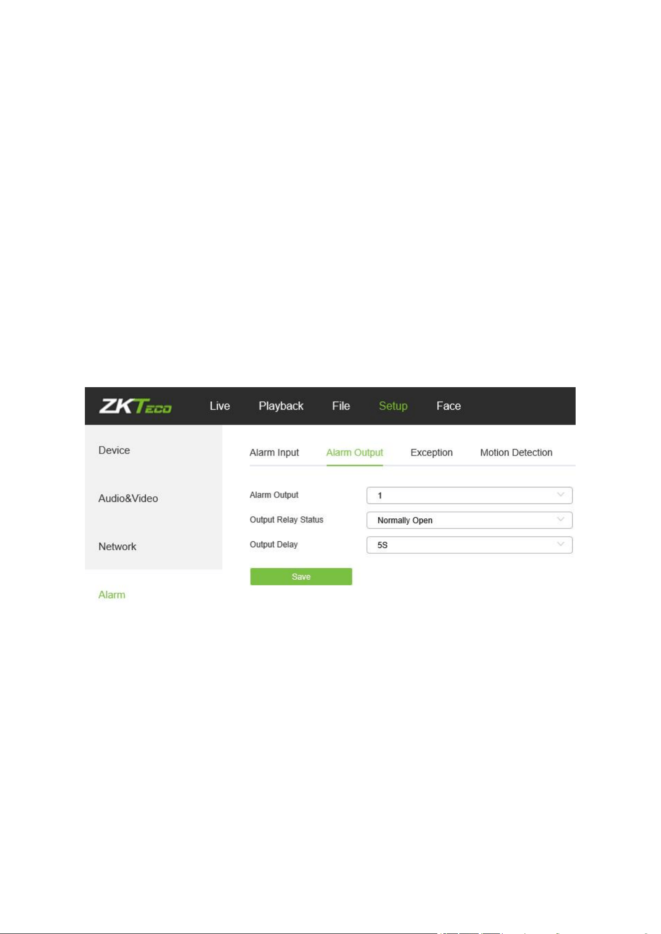
5.28 Alarm Output
Below is the Alarm Output setting interface of the IP camera:
Output Relay Status: Normally Open/ Normally Close.
Output Delay: Select alarm output delay time, which represents the corresponding output
alarm delay time after the alarm stops triggering.
After completing all parameters settings, click on “Save”, then the settings will take effect
immediately.
5.29 Exception
Below is the Exception interface of the IP camera:
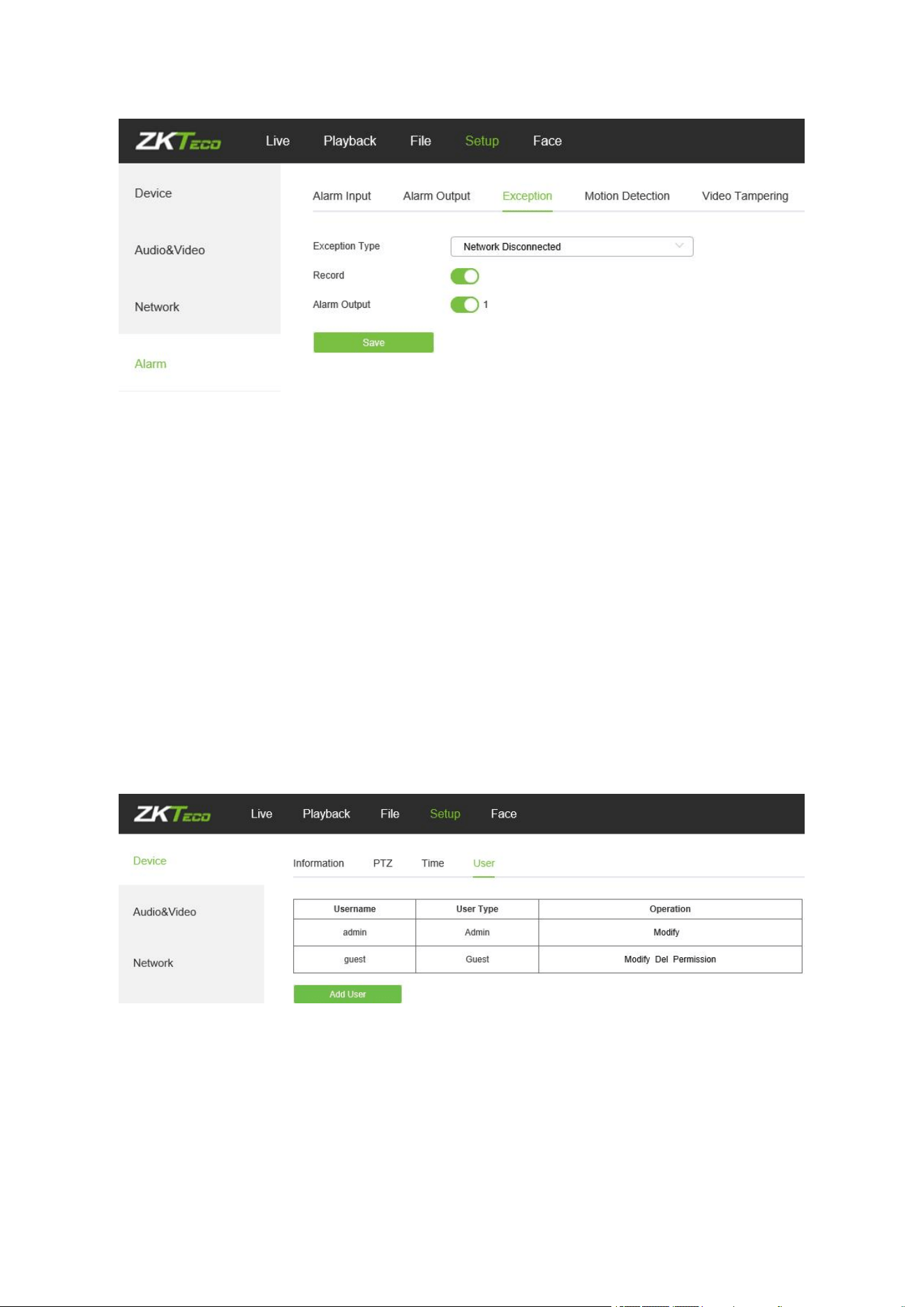
44
Exception Type: Network Disconnected/ IP Address Conflict.
Record: Click on “Record”; when there is an abnormal event which triggers an alarm, the
camera will start recording.
Alarm Output: Click on “Alarm Output”; the system will link with other alarm devices when
there is an abnormal event which triggers an alarm.
After completing all parameters settings, click on “Save”, then the settings will take effect
immediately.
5.30 User Management
Below is the User Management setting interface of the IP camera. “admin” represents the
administrator (default); “default” represents standard users.
Modify: Admin may modify the login password; the default guest user may modify user
type. New users may modify their user names, passwords and user types. New users may
select a “Guest” or “Operator” account, and set different permission.
Del: Delete a new user.
Rights Permission: Permission assignment for default guest users and new users.
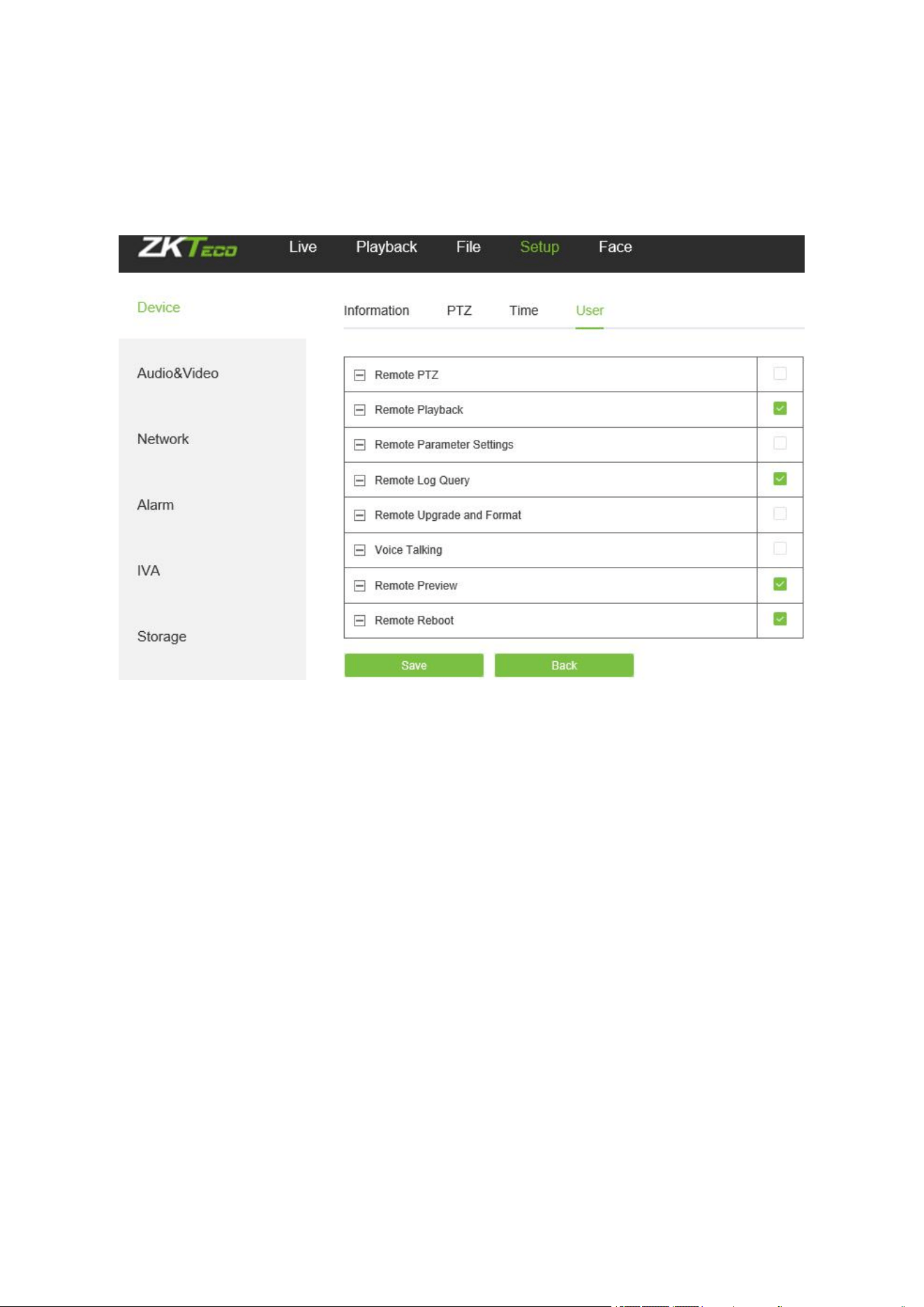
45
Add User: Add a new user.
Log in with admin account, add a new user and assign permission, as shown in the following
figure:
After completing all parameters settings, click on “Save”, then the settings will take effect
immediately.
5.31 System Update
Below is the System Update setting interface of the IP camera:
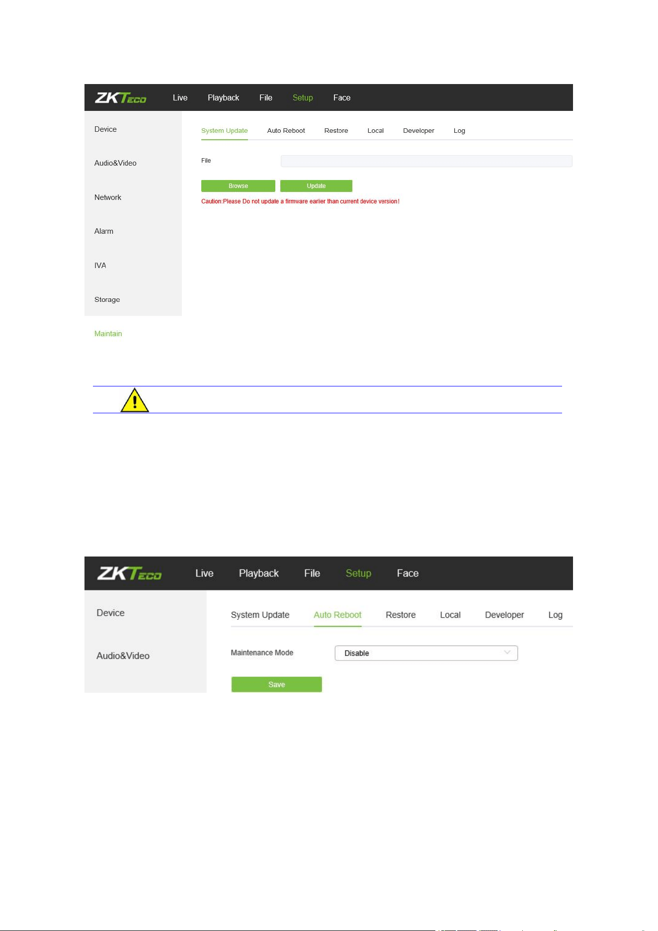
46
File: Click on “Browse” to find and select an upgrade kit, then click “Update”.
Do not disconnect the power supply during upgrade.
5.32 Auto Reboot
Below is the Auto Reboot setting interface of the IP camera. You may choose a maintenance
mode from Disable/ Every Day/ Every Week/ Once/ Every Month, then the IPC will reboot as
set.
5.33 Storage Management
(Only displayed on TF Card supported camera)
Below is the Storage Management setting interface of the IP camera. You may view the capacity
(MB), free spare (MB), status of the current TF card, and format the TF card.
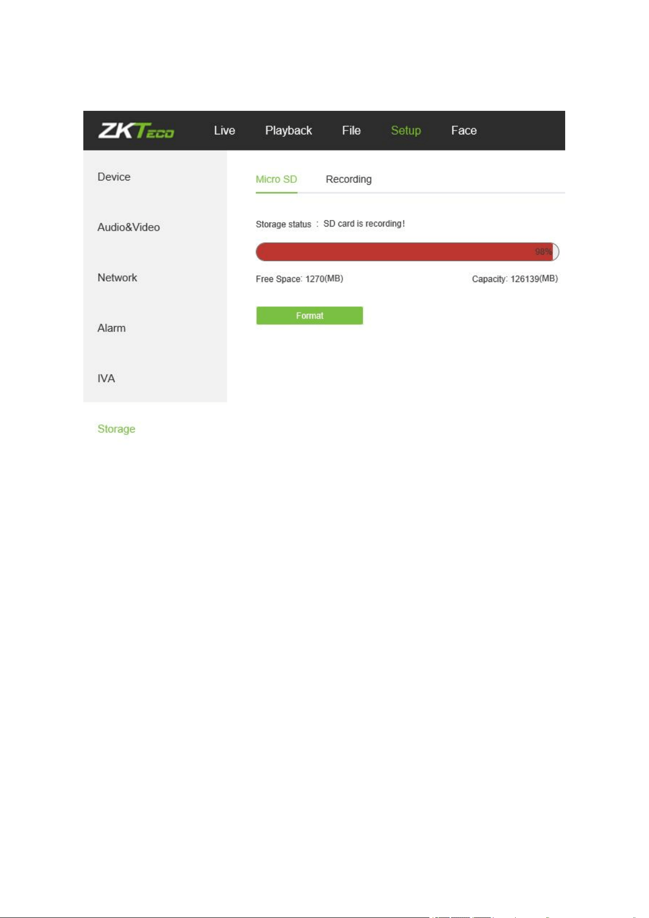
47
Note: Please disconnect the power supply before you insert or remove the TF card.
5.34 Restore
Below is the Restore interface of the IP camera:
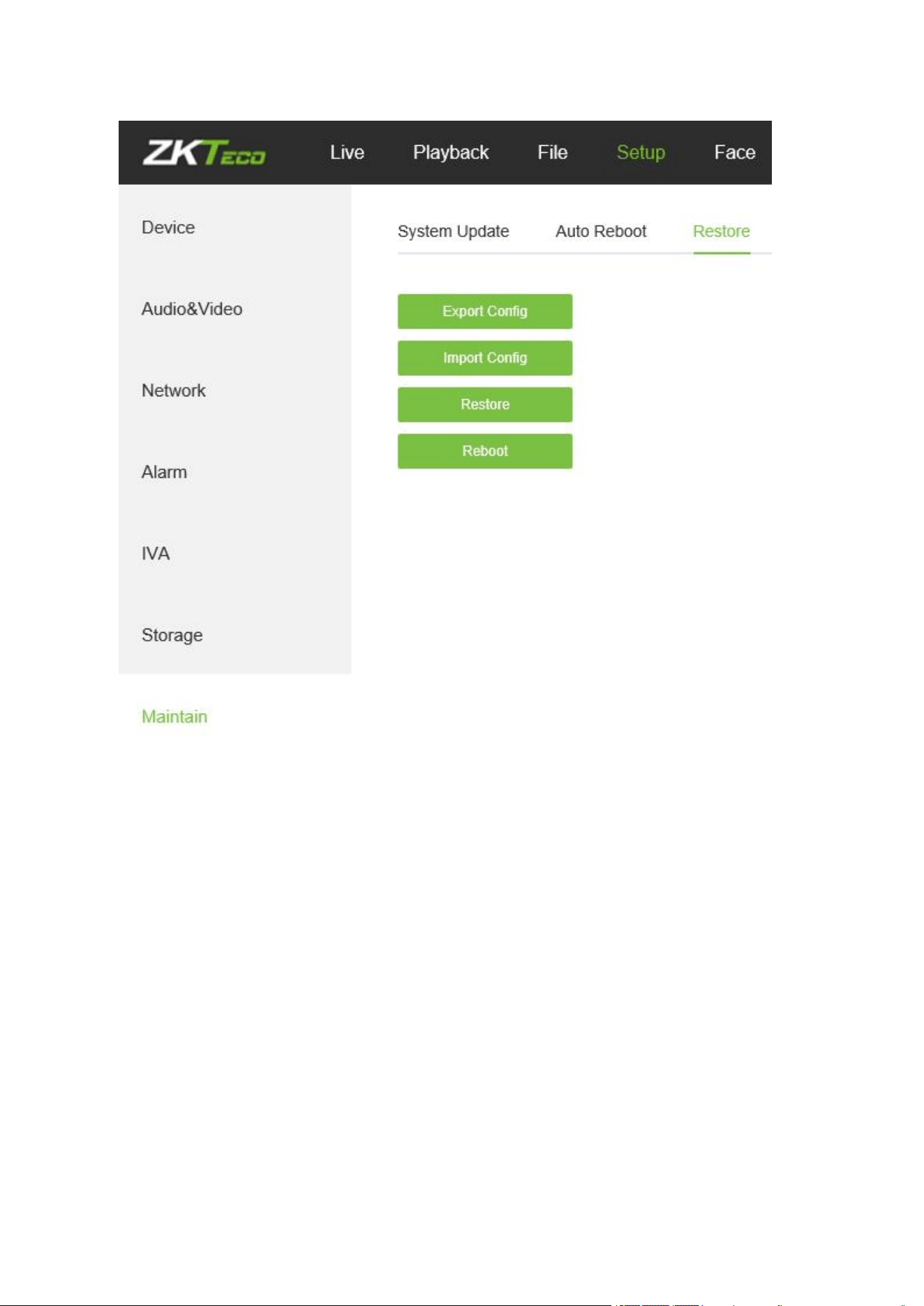
48
Export Config: Export all configurations to PC or a USB.
Import Config: Import selected configuration to the system.
Restore: Restore the device to factory settings.
Reboot: Reboot the device.
5.35 Local Settings
Below is the Local Settings interface of the IP camera:
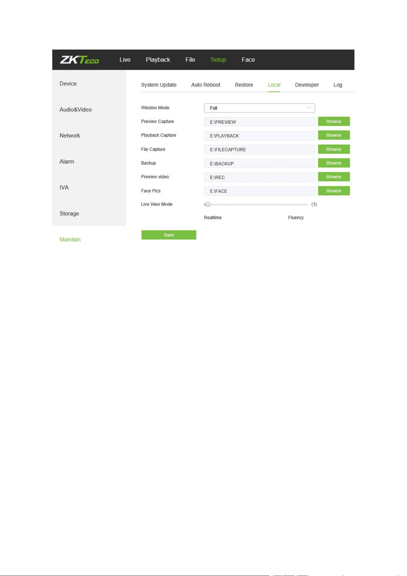
49
Window Mode: Set the preview window mode (Full/ 4:3/ 16:9/ Original Image).
Preview Capture: Select and modify the storage path of captured files.
Playback Capture: Select and modify the storage path of playback files.
File Capture: Select and modify the storage path of captured files.
Backup: Select and modify the storage path of backup files.
Preview Video: Select and modify the storage path of the video record file.
Face Pics Path: Select and modify the storage path of the video record file.
Live View Mode: Realtime/ Fluency. The value is adjustable.
After completing all parameters settings, click on “Save”, then the settings will take effect
immediately.
50
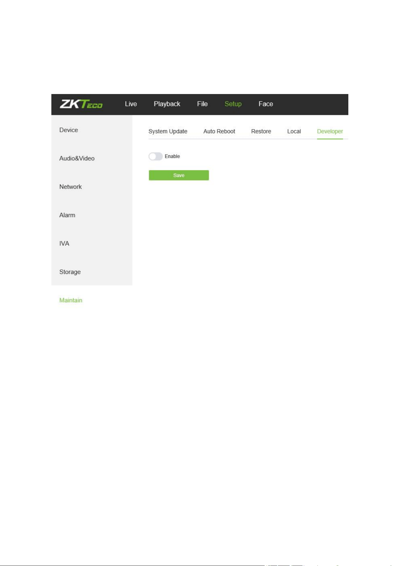
5.36 Developer
Below is the Developer interface of the IP camera:
51
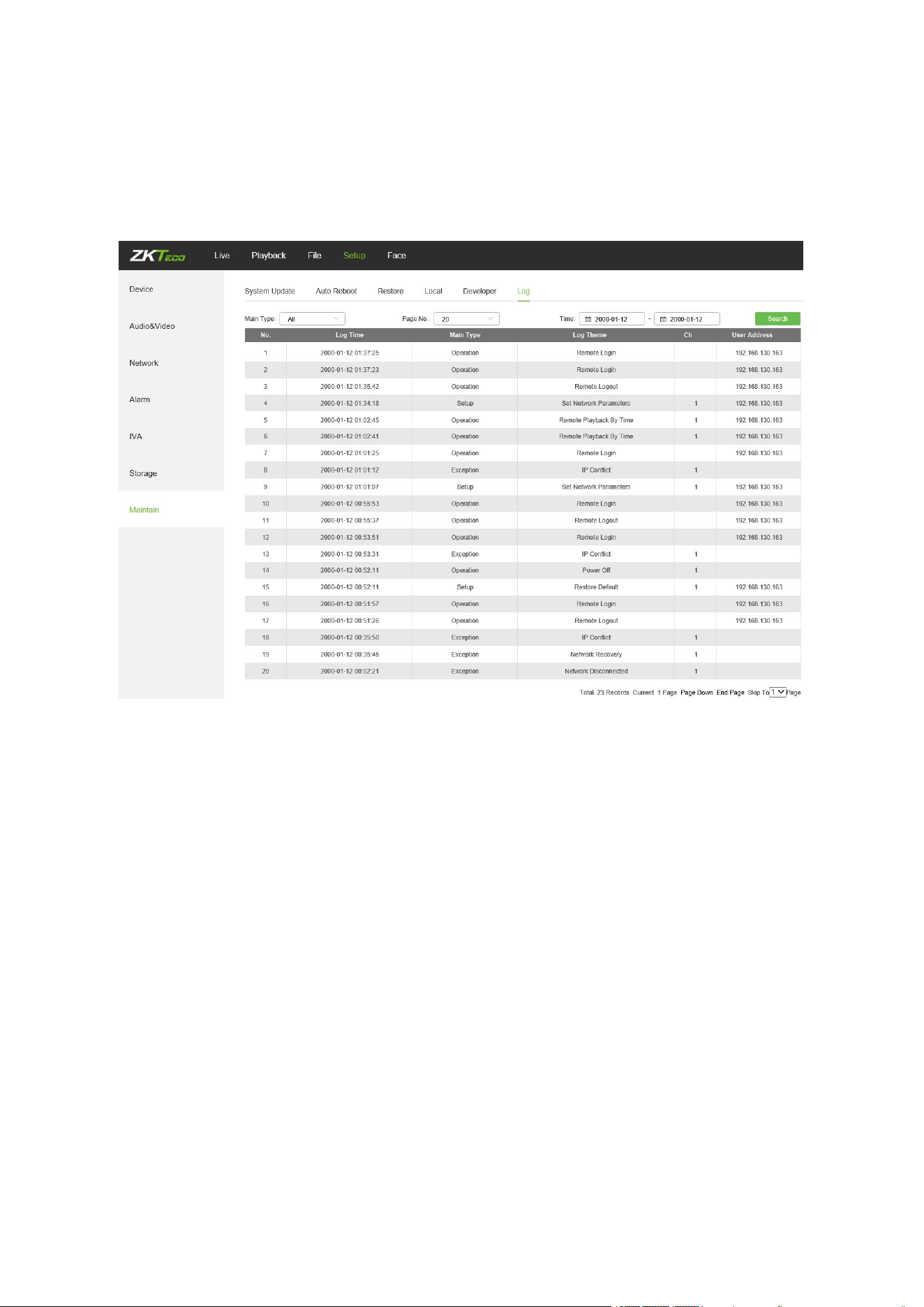
6. Log Search
Click Search on the Log interface, check device log according to the video type and date time,
as shown in the below figure:
Main Type: Select the type of logs to search for. You may choose among All/ Alarm/
Exception / Operation/Parameter or click “All” to search all types of logs.
Start Time/ End Time: Select the time period of logs to check.
Page No.: Select the number of logs to display on each page.
After completing all settings, click on “Search”, then the log information will display on the left.
52
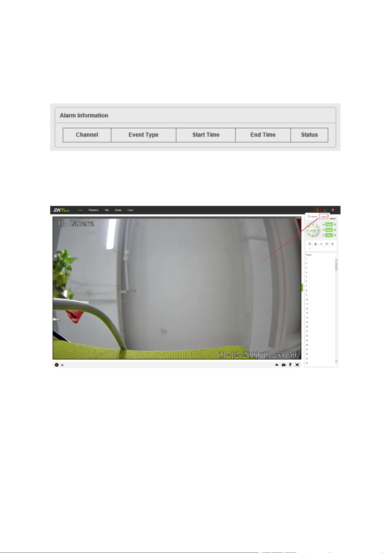
7 Alarm
Below is the Alarm interface of the IP camera. Information about alarms will be shown as
follows.
8 Exit
Click on “Logout” to log out, as shown in the following figure:
53
9 FAQ
Question 1: No video output on the IE browser.
Possible reason: The web plugin was not installed.
Solution: Download and install the web plugin according to the webpage prompt when it is
the first visit. We only support IE browser currently.
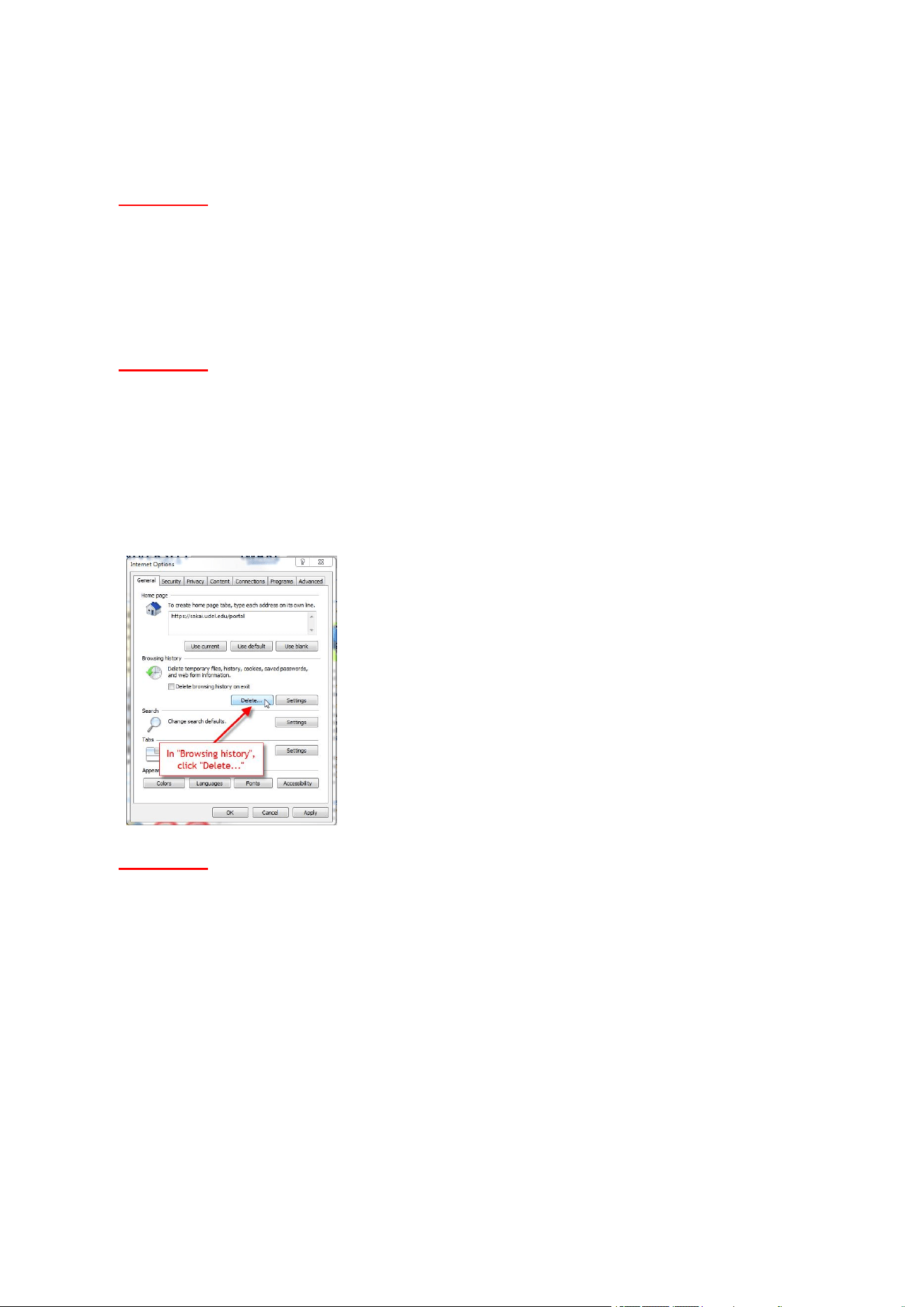
Question 2: Failed to log in after upgrading the program.
Solution: Delete IE Caches, and re-install the web plugin.
Specific steps: Open IE browser, choose “Tool” -> “Internet Options”, then,
“General”->“Browsing history”, and click on “Delete”. After that, select “Temporary Internet files”
and confirm by choosing “Delete”. Then back to the login page.
Question 3: The playback of video is not smooth.
Possible reason 1: The IP Camera frame rate is too low.
Solution: Set a higher frame rate on the respective interface by choosing
“Setup->Streams->Frame Rate”.
Possible reason 2: There are too many users connected to the device.
Solution: Disable some of the clients or set a lower frame rate for the IP camera.
Possible reason 3: The transmission data is large while the bandwidth is small, which leads to
loss of data packets.

54
Solution: Set a lower frame rate or resolution.
Question 4: Can’t access the IP camera on IE Browser?
Possible reason 1: The network is down.
Solution: Test the network on PC to confirm if the network works normally. Please make sure
the network cable is available and all RJ45 jacks are connected properly. Also, ensure that
there is no computer virus which may cause network issue as well.
If the PCs can ping each other, the network cable environment is normal. In this case, please
check the possible reasons below which may lead to the issue:
Possible reason 2: The IP address is in use by another device.
Solution: Disconnect with the IP camera network port, and directly connect the device with the
PC, then set up a new IP address for the camera.
Possible reason 3: The IP address is set up in another subnet.
Solution: Check the server’s IP address, subnet and gateway parameter, then set up the IP
camera in the same network.
Possible reason 4: The MAC address conflicted.
Solution: Modify the MAC address for IP camera.
Possible reason 5: The Web Port has been changed.
Solution: Connect with network administrator to get the correct port.
Question 5: No audio output.
Possible reason 1: The audio interface was not connected.
Solution: Please check the device audio interface and make sure the cables are connected
property.
Possible reason 2: The audio function was not enabled on the IP Camera.
Solution: Please check if the audio configuration is enabled or not and select a desired mode.
Question 6: Search NVS can’t find the device.
Possible reason: The Search NVS software uses the multicast protocol to search for device

55
network information across network segments, and the firewall does not allow multicast data
packets to pass, so the software may not find the device.
Solution: Turn off the firewall.
Question 7: The face recognition camera does not show the comparison result.
Possible reason 1: There is no relevant face information in the face database.
Solution: Add a face model. For details, please refer to Chapter 8.2 Face Database.
Possible reason 2: The corresponding face group is not enabled.
Solution: Enable the corresponding Group status. For details, please refer to Chapter 8.2 Face
Database.
Possible reason 3: The “Work Mode” does not change to “Comparison Mode”.
Solution: The working mode needs to be changed to the Comparison Mode from the face
detection menu to display the comparison result. For details, please refer to Chapter 5.20 Face
Detection.
Question 8: Image is not clear enough.
Solution: Try adjusting the parameters for images to reasonable values. For details, please
refer to Chapter 5.9 Image Parameters.
ZK Building, Wuhe Road, Gangtou, Bantian, Buji Town,
Longgang District, Shenzhen China 518129
Tel: +86 755-89602345
Fax: +86 755-89602394
www.zkteco.com
Copyright@2021 ZKTECO CO., LTD. All rights reserved.


