
Zhijian Internet (Xiamen) Information Technology Co., LTD Best Service Premium Product
———————————————————————————————————————————————————————————————————
WWW.THINKFITER.COM
Room 301, No.1 Fuchun Industrial Park Software Park Phase III, Jimei District,
Xiamen, China
1
Zhijian Internet (Xiamen) Information Technology Co., LTD
About the Manual
YQ_B2216
Bluetooth Module

Zhijian Internet (Xiamen) Information Technology Co., LTD Best Service Premium Product
———————————————————————————————————————————————————————————————————
WWW.THINKFITER.COM
Room 301, No.1 Fuchun Industrial Park Software Park Phase III, Jimei District,
Xiamen, China
2
This specification provides a basic introduction to the YQ_B2216 module, including
its electrical specifications, RF performance, pin dimensions, and reference schematic
design. Readers can refer to this document for a detailed understanding of the module's
overall functional parameters and applications. If you have any questions, please log in to
http://www.thinkfiter.com/ to contact our company or customer service.
Revision History
Version
Date
Revision History
Reviser
Auditor
V1.0
2025.12.17
OV

Zhijian Internet (Xiamen) Information Technology Co., LTD Best Service Premium Product
———————————————————————————————————————————————————————————————————
WWW.THINKFITER.COM
Room 301, No.1 Fuchun Industrial Park Software Park Phase III, Jimei District,
Xiamen, China
3
Table of Contents
About the Manual···············································································2
Revision History ·················································································2
1. Product Overview ..................................................................................................................................................................... 3
1.1 Features ..................................................................................................................................................................................... 3
1.2 Application Areas ............................................................................................................................................................. 5
2. Electrical Specifications ........................................................................................................................................................... 5
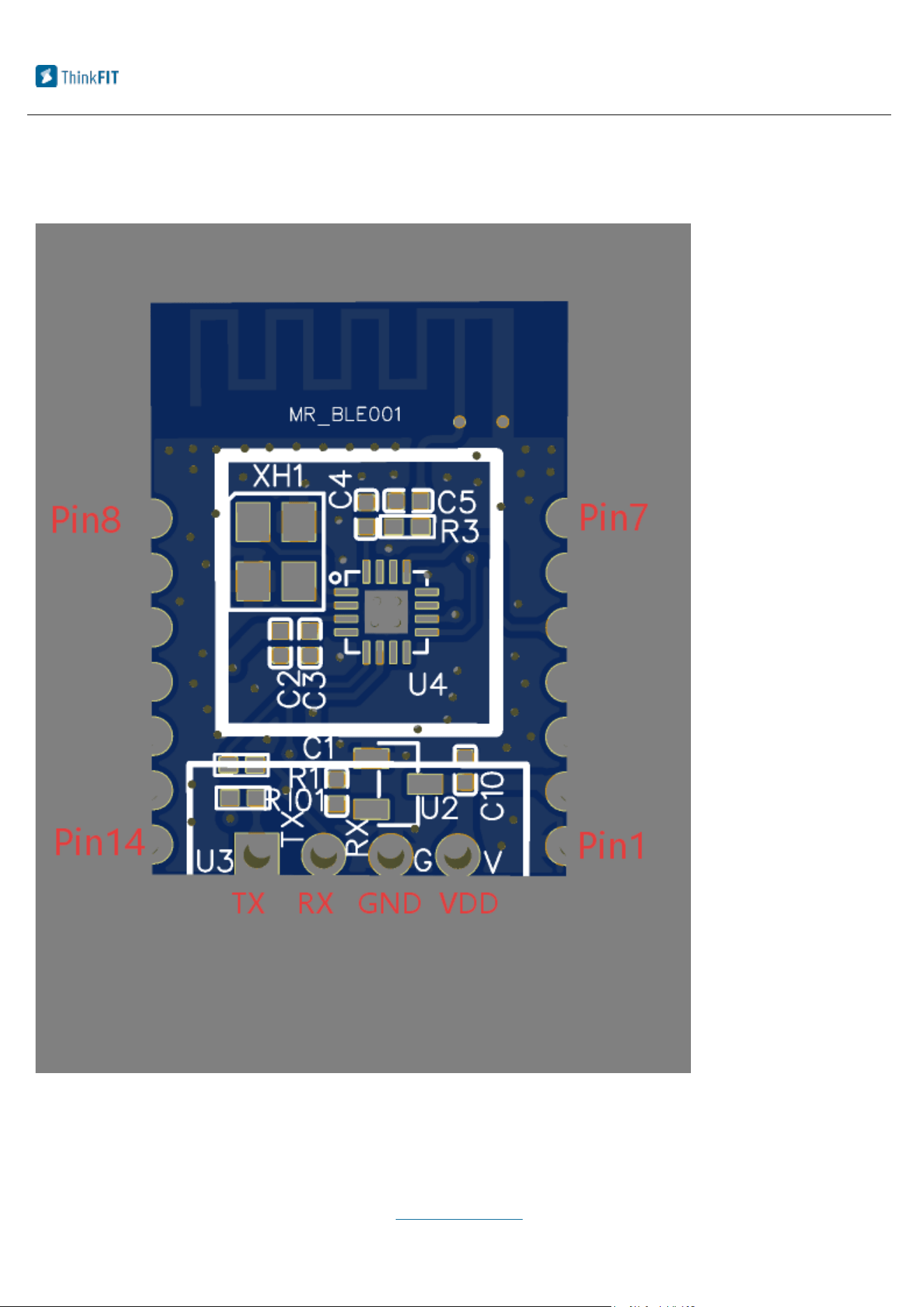
3. Pin Description ......................................................................................................................................................................... 8
4. Design Reference ..................................................................................................................................................................... 10
4.1 Module Dimensions .......................................................................................................................................................... 10
4.2 PCB Encapsulation ........................................................................................................................................................... 11
4.3 Cautions ............................................................................................................................................................................. 11
5. Furnace Parameter .............................................................................................................................................................. 12
6. OEM Guidance .......................................................................................................................................................................... 14
1. Product Overview
1.1 Features
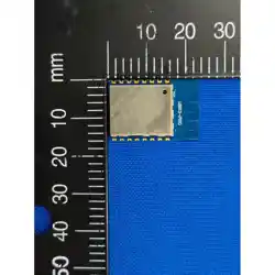
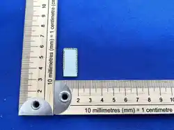
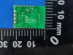
YQ_B2216 is a small-sized, low-cost Bluetooth Low Energy (BLE) standardized
transparent transmission module developed by ThinkFIT. The module supports BLE (up

Zhijian Internet (Xiamen) Information Technology Co., LTD Best Service Premium Product
———————————————————————————————————————————————————————————————————
WWW.THINKFITER.COM
Room 301, No.1 Fuchun Industrial Park Software Park Phase III, Jimei District,
Xiamen, China
4
to Bluetooth 5.2) and features a built-in 512kB FLASH memory, which supports dynamic
stack and protocol profile configurations. The product functionality can be configured
through software, providing ultimate flexibility. Additionally, it supports hardware OTA
upgrades and multiple boot switching, allowing for convenient product feature releases
and upgrades.
The module features include:
▶High Performance 32-bit MCU RSIC @48M ,256KB Flash,24KB SRAM
▶Bluetooth 5.2 Standard,RF Data link up to 2Mbps
▶Transmission Power:Maximum -3.28dBm
▶-99dBm@BLE 1Mbps;-96dBm@ BLE 2Mbps mode
▶ Support UART Interface
▶Support APP Parameter Configure
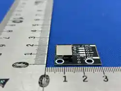
▶Snap off hole Pin + 4 PIN Terminal interface: Easy for Welding
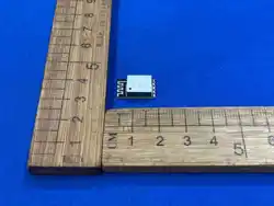
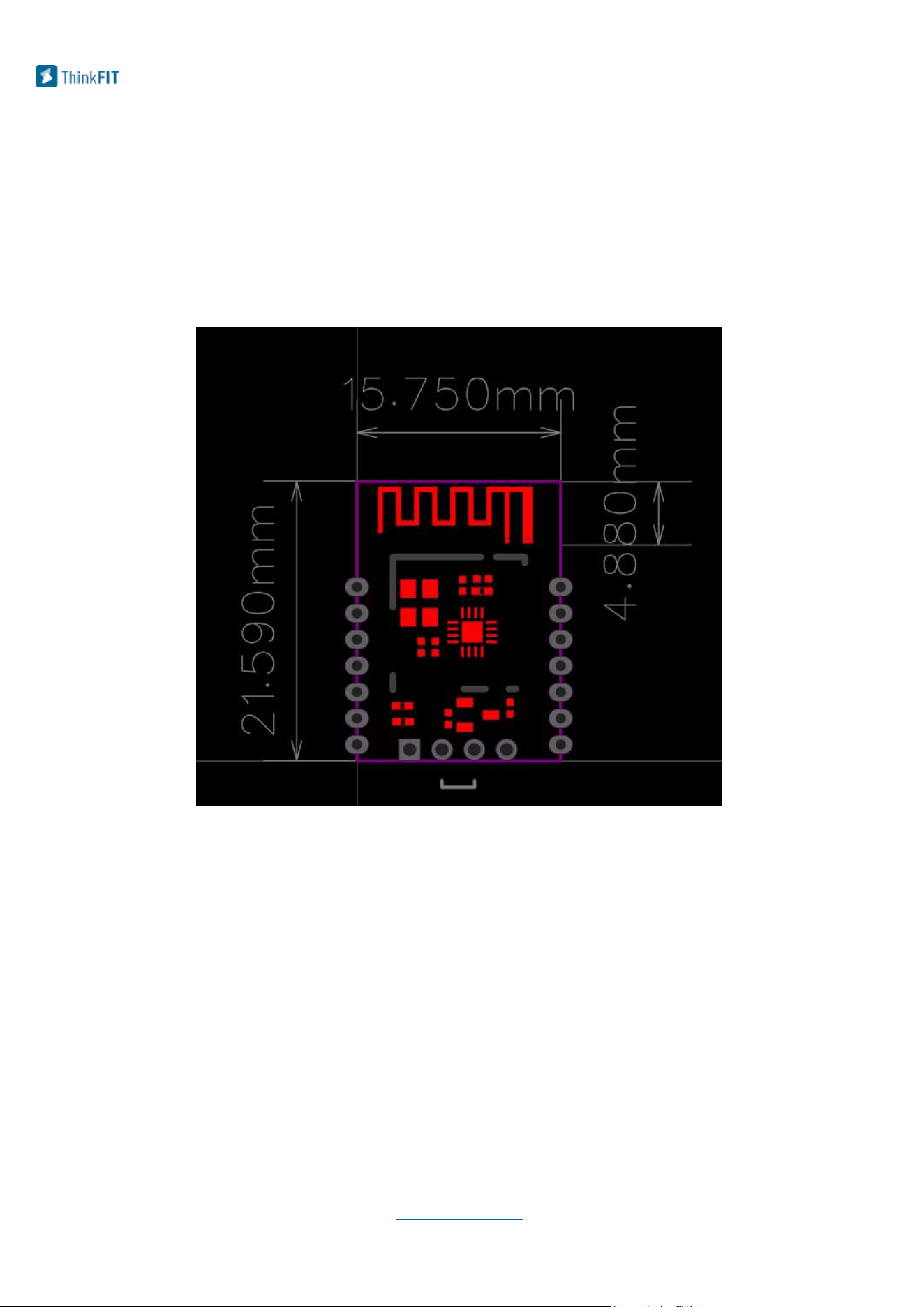
▶Compact Encapsulation:21.59x15.75mm Board Thickness 1.0mm
▶Working Temperature:-40℃~+85℃
The YQ_B2216 module only requires the connection of four wires (VCC, GND, TX,
RX) to achieve data transparent transmission functionality. It can also be applied to
various small-sized accessories or fitness products through the use of Snap off holes.
ThinkFIT has strong research and development capabilities, enabling seamless
interconnection, data transmission, and various other applications for users' Bluetooth

Zhijian Internet (Xiamen) Information Technology Co., LTD Best Service Premium Product
———————————————————————————————————————————————————————————————————
WWW.THINKFITER.COM
Room 301, No.1 Fuchun Industrial Park Software Park Phase III, Jimei District,
Xiamen, China
5
devices. Our company can customize Bluetooth modules that meet the customer's usage
specifications based on the YQ_B2216 standard version module and provide corresponding
software and hardware support according to customer requirements. For more details,
please contact our company at http://www.thinkfiter.com/ or reach out to customer
service.
1.2 Application Areas
▶Smart Jump Robes\ Ab Rollers etc.
▶Fitness Equipment like Treadmills\Exercise Bikes etc.
▶Smart Home Products
▶Industrial Control Equipment
2. Electrical Specifications
█Rated Parameter
Item
Symbol
Min
Typical
Max
Unit
Input Voltage
VCC1
3.1
3.3
12.5
V

Zhijian Internet (Xiamen) Information Technology Co., LTD Best Service Premium Product
———————————————————————————————————————————————————————————————————
WWW.THINKFITER.COM
Room 301, No.1 Fuchun Industrial Park Software Park Phase III, Jimei District,
Xiamen, China
6
Cautions:
The data listed about is only for reference purpose.Some of the data listed above may
be updated based on new testing carried out.
The showed voltage listed above is subject to the GND in the module.Voltage that
surpass the “Maximum Rated Value”will cause permanent damage to the device
█Working Current
Note:Power consumption test conditions:Whole Module Working @0dBm With DCDC
enable
█RF Parameter
(4pin terminal )
Input Voltage
(Snap off Hole)
VCC2
2.8
3.0
3.6
V
Serial Voltage
TX/RX
3.0
3.3
V
Storage Temperature
T-STR
-65
25
150
℃
Welding Temperature
T-SLD
260
℃
Item
Symbol
Min
Typical
Max
Unit
RX Current
Irx
5.3
mA
TX Current
Itx
4.8
mA

Zhijian Internet (Xiamen) Information Technology Co., LTD Best Service Premium Product
———————————————————————————————————————————————————————————————————
WWW.THINKFITER.COM
Room 301, No.1 Fuchun Industrial Park Software Park Phase III, Jimei District,
Xiamen, China
7
Item
Symbol
Min
Typical
Max
Unit
Frequency
Range
Freq.
2402
-
2480
MHz
Data Rate
BLE 1Mbps
BLE 2Mbps

Zhijian Internet (Xiamen) Information Technology Co., LTD Best Service Premium Product
———————————————————————————————————————————————————————————————————
WWW.THINKFITER.COM
Room 301, No.1 Fuchun Industrial Park Software Park Phase III, Jimei District,
Xiamen, China
9
█Port Description
Pin #
Name
Type
Description
1
GND
PWR
Ground terminal
2
VCC
PWR
3.0V power
3
NC
/
4
NC
/
5
IO20
I/O
GPIO20/FUN1~7:QSPI_D0/UART0_RX/SPIM1_SCK
I2C0_SCL/Reserved/PWM_6_P
6
TX
I/O
GPIO5/FUN1~7:QSPI_D3/UARTI_TX/SPIM1_NCS
SPIS0_SCK/UART0_TX/Reserved/PWM_5_P
7
RX
I/O
GPIO4/FUN1~7:QSPI_NCS/UARTI_RX/SPIM1_SCK
SPIS0_NCS/UART0_RX/Reserved/PWM_4_P
8
NC
/
9
TCK
I/O
GPIO0/FUN1~7:SWDCLK(default)/I2C0_SCL
SPIM0 NCS/UART0_CTS
SPIS0_NCS/Reserved/PWM_0_P
10
TMS
I/O
GPIO1/FUN1 7:SWDTMS (default)/I2C0_SDA
SPIM0_SCK/UART0_RTS
SPIS0_SCK/Reserved/PWM_1_P
11
NC
/
12
NC
/
13
NC
/
14
NC
/
Zhijian Internet (Xiamen) Information Technology Co., LTD Best Service Premium Product
———————————————————————————————————————————————————————————————————
WWW.THINKFITER.COM
Room 301, No.1 Fuchun Industrial Park Software Park Phase III, Jimei District,
Xiamen, China
10
4. Design Reference
4.1 Module Dimensions
Zhijian Internet (Xiamen) Information Technology Co., LTD Best Service Premium Product
———————————————————————————————————————————————————————————————————
WWW.THINKFITER.COM
Room 301, No.1 Fuchun Industrial Park Software Park Phase III, Jimei District,
Xiamen, China
11
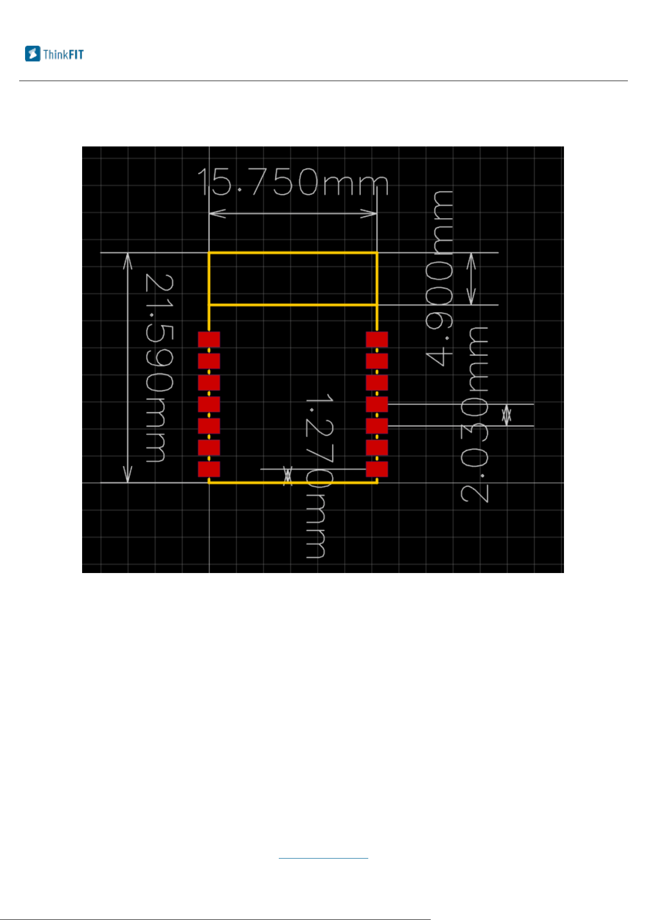
4.2 PCB Encapsulation
4.3 Cautions
The blue-tooth working frequency should be 2.4GHZ and It is suggested to use the
device in a environment where interference factor can be minimized.
Cautions
▶ Avoid using metal materials in the shell of the knob.
▶ Avoid placing metal screws and other parts too close to the radio frequency part.

Zhijian Internet (Xiamen) Information Technology Co., LTD Best Service Premium Product
———————————————————————————————————————————————————————————————————
WWW.THINKFITER.COM
Room 301, No.1 Fuchun Industrial Park Software Park Phase III, Jimei District,
Xiamen, China
12
▶To maximize RF performance, users should follow the following recommendations
for PCB layout:
1) (Antenna Clearance Area:)The user's main board, located directly below the
antenna area of the module, should not have any copper foil (including power,
ground, and signal layers).
2) Module placement:Ideally, the module should be placed in one corner of the
user's main board, with the PCB antenna positioned at the far end of the board.
This placement helps minimize the antenna clearance area to the lowest possible
extent.
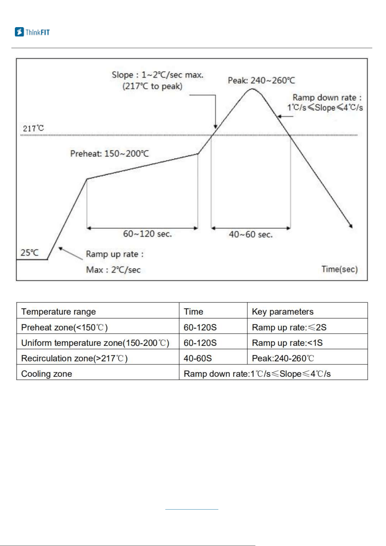
5. Furnace Parameter
█Refer to the following parameter

Zhijian Internet (Xiamen) Information Technology Co., LTD Best Service Premium Product
6. OEM Guidance
1. Applicable FCC rules
This module has been tested and found to comply with part 15.247 requirements for
Modular Approval.
2. The specific operational use conditions
This module can be used in IoT devices. The input voltage to the module is nominally 3.3V DC.
The operational ambient temperature of the module is -40 to +85 degree C. Only
the embedded PCB antenna is allowed. Any other external antenna is prohibited.
3. Limited module procedures
N/A
4. Trace antenna design
N/A
5. RF exposure considerations
This equipment complies with FCC radiation exposure limits set forth for an uncontrolled
environment .This equipment should be installed and operated with minimum distance 20cm
between the radiator& your body. This transmitter must not be located or operating in
conjunction with any other antenna or transmitter.
6. Antenna
Antenna type : PCB Antenna; Antenna Max. Peak Gain 1.56dBi
7. Label and compliance information
When the module is installed in the host device, the FCC ID label must be visible through a
window on the final device or it must be visible when an access panel, door or cover is easily
re-moved. If not, a second label must be placed on the outside of the final device that contains
the following text: “Contains FCC ID: 2BGXU-YQ-B2216”
The FCC ID can be used only when all FCC ID compliance requirements are met.
8. Information on test modes and additional testing requirements
——————————————————————————————————————————————————————————————————
—
14
WWW.THINKFITER.COM
Room 301, No.1 Fuchun Industrial Park Software Park Phase III, Jimei District,
Xiamen, China

Zhijian Internet (Xiamen) Information Technology Co., LTD Best Service Premium Product
———————————————————————————————————————————————————————————————————
WWW.THINKFITER.COM
Room 301, No.1 Fuchun Industrial Park Software Park Phase III, Jimei District,
Xiamen, China
15
a)The modular transmitter has been fully tested by the module grantee on the required
number of channels, modulation types, and modes, it should not be necessary for the host
installer to re-test all the available transmitter modes or settings. It is recommended that the
host product manufacturer, installing the modular transmitter, perform some investigative
measurements to confirm that the resulting composite system does not exceed the spurious
emissions limits or band edge limits (e.g., where a different antenna may be causing
additional emissions).
b)The testing should check for emissions that may occur due to the intermixing of emissions
with the other transmitters, digital circuitry, or due to physical properties of the host product
(enclosure). This investigation is especially important when integrating multiple modular
transmitters where the certification is based on testing each of them in a stand-alone
configuration. It is important to note that host product manufacturers should not assume that
because the modular transmitter is certified that they do not have any responsibility for final
product compliance.
c)If the investigation indicates a compliance concern the host product manufacturer is
obligated to mitigate the issue. Host products using a modular transmitter are subject to all
the applicable individual technical rules as well as to the general conditions of operation in
Sections 15.5, 15.15, and 15.29 to not cause interference. The operator of the host product
will be obligated to stop operating the device until the interference have been corrected .
9. Additional testing, Part 15 Subpart B disclaimer
The final host / module combination need to be evaluated against the FCC Part 15B criteria for
unintentional radiators in order to be properly authorized for operation as a Part15 digital
device.
The host integrator installing this module into their product must ensure that the final
composite product complies with the FCC requirements by a technical assessment or evaluation
to the FCC rules, including the transmitter operation and should refer to guidance in KDB
996369. For host products with certified modular transmitter, the frequency range of
investigation of the composite system is specified by rule in Sections 15.33(a)(1) through (a)(3),
or the range applicable to the digital device, as shown in Section 15.33(b)(1), whichever is the
higher frequency range of investigation. When testing the host product, all the transmitters
must be operating. The transmitters can be enabled by using publiclyavailable drivers and
turned on, so the transmitters are active. In certain conditions it might be appropriate to use a
technology-specific call box (test set) where accessory devices or drivers are not available. When
testing for emissions from the unintentional radiator, the transmitter shall be placed in the
receive mode or idle mode, if possible. If receive mode only is not possible then, the radio shall
be passive (preferred) and/or active scanning. In these cases, this would need to enable activity

Zhijian Internet (Xiamen) Information Technology Co., LTD Best Service Premium Product
———————————————————————————————————————————————————————————————————
WWW.THINKFITER.COM
Room 301, No.1 Fuchun Industrial Park Software Park Phase III, Jimei District,
Xiamen, China
16
on the communication BUS (i.e., PCIe, SDIO, USB) to ensure the unintentional radiator circuitry is
enabled.
Testing laboratories may need to add attenuation or filters depending on the signal strength of
any active beacons (if applicable) from the enabled radio(s). See ANSI C63.4, ANSI C63.10 for
further general testing details.
FCC Statement
Any Changes or modifications not expressly approved by the party responsible for compliance
could void the user’s authority to operate the equipment.
This device complies with part 15 of the FCC Rules. Operation is subject to the following two
conditions:
(1) This device may not cause harmful interference, and
(2) This device must accept any interference received, including interference that may cause
undesired operation.
FCC Radiation Exposure Statement:
This equipment complies with FCC radiation exposure limits set forth for an uncontrolled
environment .This equipment should be installed and operated with minimum distance 20cm
between the radiator& your body. This transmitter must not be located or operating in
conjunction with any other antenna or transmitter.
Note : This equipment has been tested and found to comply with the limits for a Class B digital
device, pursuant to part 15 of the FCC Rules. These limits are designed to provide reasonable
protection against harmful interference in a residential installation. This equipment generates,
uses and can radiate radio frequency energy and, if not installed and used in accordance with
the instructions, may cause harmful interference to radio communications. However, there is no
guarantee that interference will not occur in a particular installation. If this equipment does
cause harmful interference to radio or television reception, which can be determined by turning
the equipment off and on, the user is encouraged to try to correct the interference by one or
more of the following measures:
—Reorient or relocate the receiving antenna.
—Increase the separation between the equipment and receiver.
—Connect the equipment into an outlet on a circuit different from that to which the receiver is
connected.
—Consult the dealer or an experienced radio/TV technician for help.