Note: Please read this user manual carefully
before installation and use!
DS310
Wireless Sensor
User Manual
DHMS (Hong Kong) Intelligent Technology Limited
Implementation Standards:
GB/T3836.1-2021
GB/T3836.4-2021
Q/3205DMS01001-2025

Important Notes:
1. The product is strictly prohibited from
being installed in an environment
containing flammable and explosive gases.
2. To avoid dangerous accidents, the
installation and fixation of the product
must be carried out in strict accordance
with the instruction manual.
3. After removing the packaging, check
whether the product is damaged.

1 Product Overview
1.1 Product Introduction
The DS310 sensor is a wireless vibration and
temperature sensor, which is used for condition
monitoring of rotating dynamic equipment in
industrial fields. This wireless sensor is powered
by a battery, can collect vibration/temperature
data in three axial directions, connects to the
gateway via Bluetooth, and uploads the monitored
data to the gateway.
2 Main Technical Parameters
Category
Specifications
Communication
Communic
ation
Protocol
Bluetooth 5.0
Vibration
Acquisition
Acquisition
Type
Three - axis
Vibration
Acquisition
Vibration
Frequency
6 KHz@3dB
Range
16 g
Temperature
Acquisition
Range
-20℃ to 120 ℃
Resolution
0.1 ℃
Working
Environment
Working
Temperatur
e
-20℃ to 80 ℃
Working
Humidity
5% to 90%, non
- condensing
Housing
Protection
Level
IP69
Size
46
×
36
×
30 mm
Installation
Method
Adhesive
Method
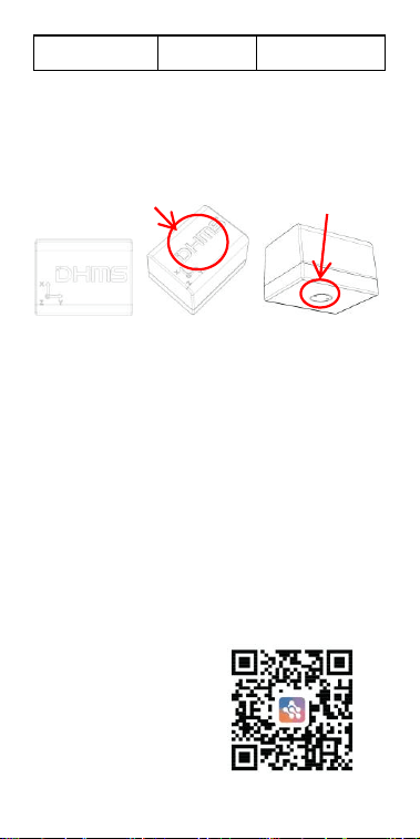
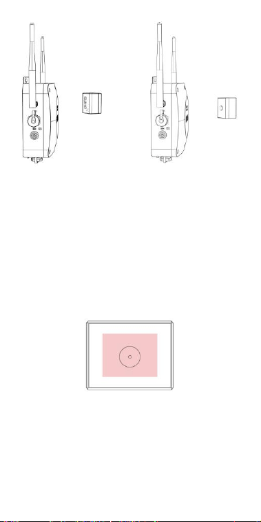
3 Product Appearance
Top View Overhead View Bottom View
4 Installation and Operation
4.1 Confirmation of the Number and
Location of Monitoring Points
Open the DHMSCare APP, click on the added
target monitoring device, and determine the
number of monitoring points (i.e., the number of
sensors) and their locations (i.e., the installation
positions of the sensors) according to the guidance
on the APP page.
Scan the QR code on
the right to download
the APP.
Temperature
measurement point
NFC area
4.2 Placing the Sensor
Read the following installation precautions:
4.2.1 The sensor should be installed close to the
bearing (note to avoid installing it at the fan
outlet);
4.2.2 The installation position on the equipment
casing must be clean and flat, without grease, dust,
and so on;
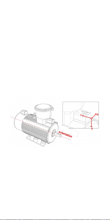
4.2.3 The "Y-axis" of the sensor is parallel to the
axial direction of the equipment, and the "Z-axis"
of the sensor is perpendicular to the axial
direction of the equipment.
Reference for Sensor Installation Diagrams
4.2.4 The communication signal between the
sensor and the gateway is optimal when the top
surface of the sensor (the side with the LOGO)
faces the gateway.
Correct Example Diagram Incorrect Example Diagram
4.3 Installation and Fixation
4.3.1 After determining the installation position
and direction, apply glue (Loctite 454 is
recommended) evenly to the bottom case. Ensure
the glue layer is not too thick (less than 2mm).
Apply the glue to the area marked red in the
figure below, covering approximately 60% of the
bottom surface.
4.3.2 After applying the glue, press the sensor
onto the designated position. Release your hand
after the glue has initially set (the initial setting
time varies depending on the type of glue. For
example, Loctite 454 glue takes approximately
Front
(logo side)
Back
5-20 seconds).
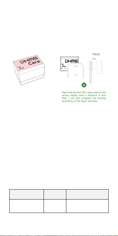
4.4 Monitoring Point Binding
Open the DHMSCare APP, Then follow the APP
prompts to complete the binding of the sensor.
Note: After binding, the sensor will
automatically search for nearby gateways to
connect to the network, and no other
operations are required.
5 Judgment of Bluetooth Signal
Strength at the Sensor Installation
Position
The mobile APP allows checking the Bluetooth
signal strength reported by the sensor to evaluate
the quality of the Bluetooth signal at the
installation location.
Signal Strength
Judgmen
t
Solutions
> -60 dBm
Strong
-
The red-marked position
in the diagram is the
NFC sensing area.

From -60 dBm
to -75 dBm
Medium
-
<-75 dBm
Poor
1. Change the
installation position
of the sensor.
2. Adjust the
direction of the
sensor's top surface.
6 Fault Analysis and
Troubleshooting
If the above measures fail to resolve the issue,
please contact the manufacturer or an authorized
dealer for assistance!
Phenomeno
n
Possible Fault
Causes
Solutions
The sensor
shows
offline
There is no
Bluetooth signal
or the signal is
poor at the
installation point.
Adjust the
positions of the
gateway /
sensor.
There are metal
obstructions
between the
sensor and the
gateway.
Remove metal
obstructions.
The
collected
data is
obviously
incorrect
The sensor is
loose or has
fallen off.
Re-fix the
sensor on the
equipment.

7 Maintenance and Care
After-sales service for the product must be
provided by the manufacturer or authorized
distributor;
Non-professional maintenance personnel are
strictly prohibited from disassembling the internal
components. Unauthorized disassembly will
invalidate the warranty;
BLE(1 Mbps/2 Mpbs):2402-2480 MHz
BLE(1 Mbps): 14.87 dBm
BLE(2 Mbps): 14.82 dBm
FCC Statement
Any Changes or modifications not expressly
approved by the party responsible for compliance
could void the user’s authority to operate the
equipment.
This device complies with part 15 of the FCC Rules.
Operation is subject to the following two conditions:
(1) This device may not cause harmful interference,
and
(2) This device must accept any interference
received, including interference that may cause
undesired operation.
FCC Radiation Exposure Statement:
This equipment complies with FCC radiation
exposure limits set forth for an uncontrolled
environment. This equipment should be installed and
operated with minimum distance 20cm between the
radiator& your body.

19H Maxgrand Plaza, No.3 Tai Yau Street, San Po Kong,
Kowloon, Hong Kong SAR, China
Contact Number: 0852-6213-9846
Note : This equipment has been tested and
found to comply with the limits for a Class B
digital device, pursuant to part 15 of the FCC
Rules. These limits are designed to provide
reasonable protection against harmful
interference in a residential installation. This
equipment generates,uses and can radiate
radio frequency energy and, if not installed
and used in accordance with the instructions,
may cause harmful interference to radio
communications. However, there is no
guarantee that interference will not occur in a
particular installation. If this equipment does
cause harmful interference to radio or
television reception, which can be determined
by turning the equipment off and on, the user
is encouraged to try to correct the interference
by one or more of the following measures:
—Reorient or relocate the receiving antenna.
—Increase the separation between the
equipment and receiver.
—Connect the equipment into an outlet on a
circuit different from that to which the
receiver is connected.
—Consult the dealer or an experienced radio/
TV technician for help.