Instruction Manual
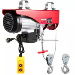
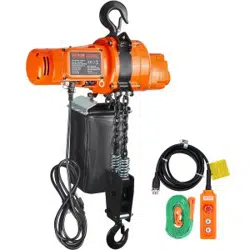
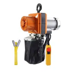
Mini Electric Chain Hoist
H2.5 H5 H10
READY THIS MANUAL BEFORE USING THESE PRODUCTS
This manual contains important safety, installation, operation
and maintenance information. Make this manual available
to all persons responsible for the operation, installation and
maintenance of the electric chain hoist.
a
t
i
o
n
z
i
f
n
o
a
r
g
S
r
t
a
O
n
l
d
a
a
n
r
o
i
d
t
i
a
z
a
n
r
t
i
e
o
t
n
n
I
9001
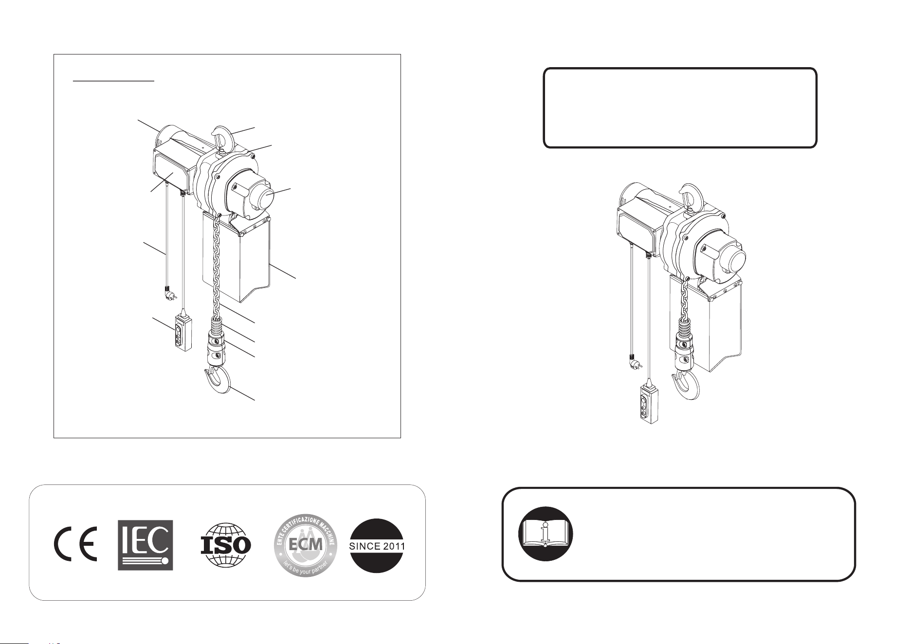
Upper Hook
Gear Case
Brake Case
Chain Container
Load Chain
Buffering Spring
Chain Stopper
Lower Hook
Switch
Power Cable
Motor
Controller Cover
Parts name

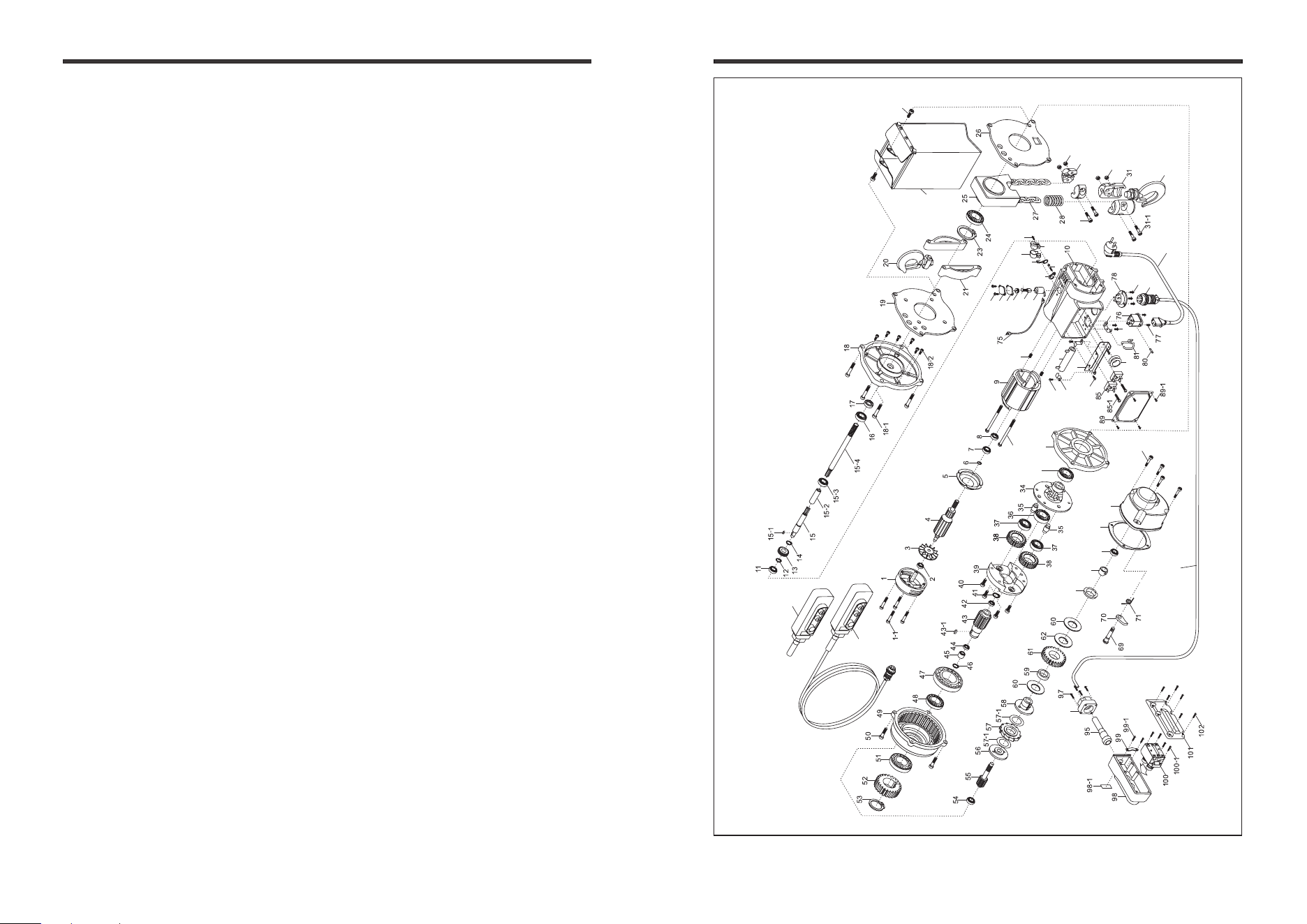
9. Parts List
1.Technical information.................................................2
1.1 Specifications
1.2 Dimensions
2. Pre-operational Procedures.......................................3
2.1 Chain
2.2 Load chain Lubrication
2.3 Mounting Hoist
2.4 Electrical Connections
2.5 Pre-operational Checks and Trial Operation
2.6 Environmental Precaution
3.Operation..................................................................4
3.1 Introduction
3.2 Handling Precautions
4.Inspection.................................................................5
4.1 Inspection classification
5. Maintenance and Replacement
5.1 Lubrication........................................................ 6
5.1 Carbon Brush Replacement
5.3 Load chain replacement
5.4 Mechanical Load Brake with Friction Clutch
5.5 Fuses
5.6 Outdoor Installation
6.Trouble Shootings.....................................................9
7.Wiring Diagram........................................................11
8. Spare Parts Drawing- H2.5,H5 ..............................12
Spare Parts Drawing- H10
9. Parts List .............................................................14
.
1 14
Table of Contents 9. Parts List
No. Parts description
1-1 Socket Bolt
2 Bearing
3 Fan
4 Armature
5 Air Guiding Cover
6 Retaining Ring
7 Bearing
8 Oil Seal
9 Stator
9-1 Socket Bolt
9-2 Headless Screw
10 Motor Case
11 Bearing
12 Retaining Ring
13 First Reduction Gear
14 Retaining Ring
15 First Reduction Pinion A
15-1 Key
15-2 Spline Housing
15-3 Bearing
15-4 First Reduction Pinion B
16 Bearing
17 Oil Seal
18 Gear Left Cover
18-1 Socket Bolt
18-2 Socket Bolt
18-3 Lock Nut (H10)
18-4 Chain Anchorage (H10)
19 Left Sheet
20 Upper Hook
21 Spacer
22 Gear Right Cover
23 Retaining Ring
24 Bearing
25 Chain Guide House
26 Right Sheet
27 Load Chain (6.3MM)
27-1 Chain Guide
28 Buffering Spring
29 Chain Stopper
29-1 Socket Bolt
29-2 Locknut
30 Idle Sheave
31 Lower Hook Holder
31-1 Socket Bolt
31-2 Supporting Spacer
31-3 Locknut
31-4 Socket Bolt
31-6 Socket Bolt
31-5 Locknut
31-7 Spacer
No. Parts description
31-8 Locknut
31-9 Needle Bearing
32 Lower Hook
33 Hanger Hook
33-1 Cable Hanger
33-2 Rubber Hanger
33-3 Screw
33-4 Twin-hole Suspender
33-5 Socket Bolt
34 Load Sheave
35 Support
36 Bearing
36-1 Bearing
37 Bearing
38 Planet Driven Gear
39 Gear Support
40 Socket Bolt
41 Retaining Ring
42 Oil Seal
43 Sun Gear
43-1 Key
44 Oil Seal
45 Needle Bearing
46 Retaining Ring
47 Bearing
48 Bearing
49 Gear Case
50 Socket Bolt
51 Bearing
52 Second Driving Gear
53 Retaining Ring
54 Bearing
55 Second Driven Pinion
56 Brake Seat
57 Ratchet Disc
57-1 Brake Disc
58 Torque Gear Seat
59 Copper Cover
60 Press Spring Disc
61 Torque Gear
62 Brake Washer
63 Torque Limited Nuts
64 Anti-receding Bushing
65 Bearing
66 Gasket
67 Brake Case
68 Socket Bolt
69 Pawl Pin
70 Pawl
71 Pawl Spring
72 Chain Container
73 Socket Bolt
No. Parts description
75 Carbon Cable
76 Power Socket
77 Screw
78 Switch Socket
79 Screw
80 Fuse
81 Power Cable Hanger
82 Holder
83 Screw
84 Resistor
84-1 Resistor Feet
84-2 Screw
85 Bridge Regulator
85-1 Screw
86 Insulation Sheath
87 Bracket
88 Screw
89 Controller Cover
89-1 Screw
90 Carbon Brush Holder
91 Carbon Brush
92 Carbon Brush Cap
92-2 Protective Cover 2
92-3 Screw
92-1 Protective Cover 1
93 Switch with Cable Set
93-1 Control Cable
93-2 Connector
94 Power Cable
95 Cable Sheath
96 Cable Packing
97 Screw
98 Switch Box
98-1 Sticker
99 Cable Fixing Plate
99-1 Screw
100 Internal Switch Connector
100-1 Screw
101 Switch Cover
102 Screw
115 Lower Hook Assy (H10)
1 Motor Cover
Switch Without Cable
114
Section Page
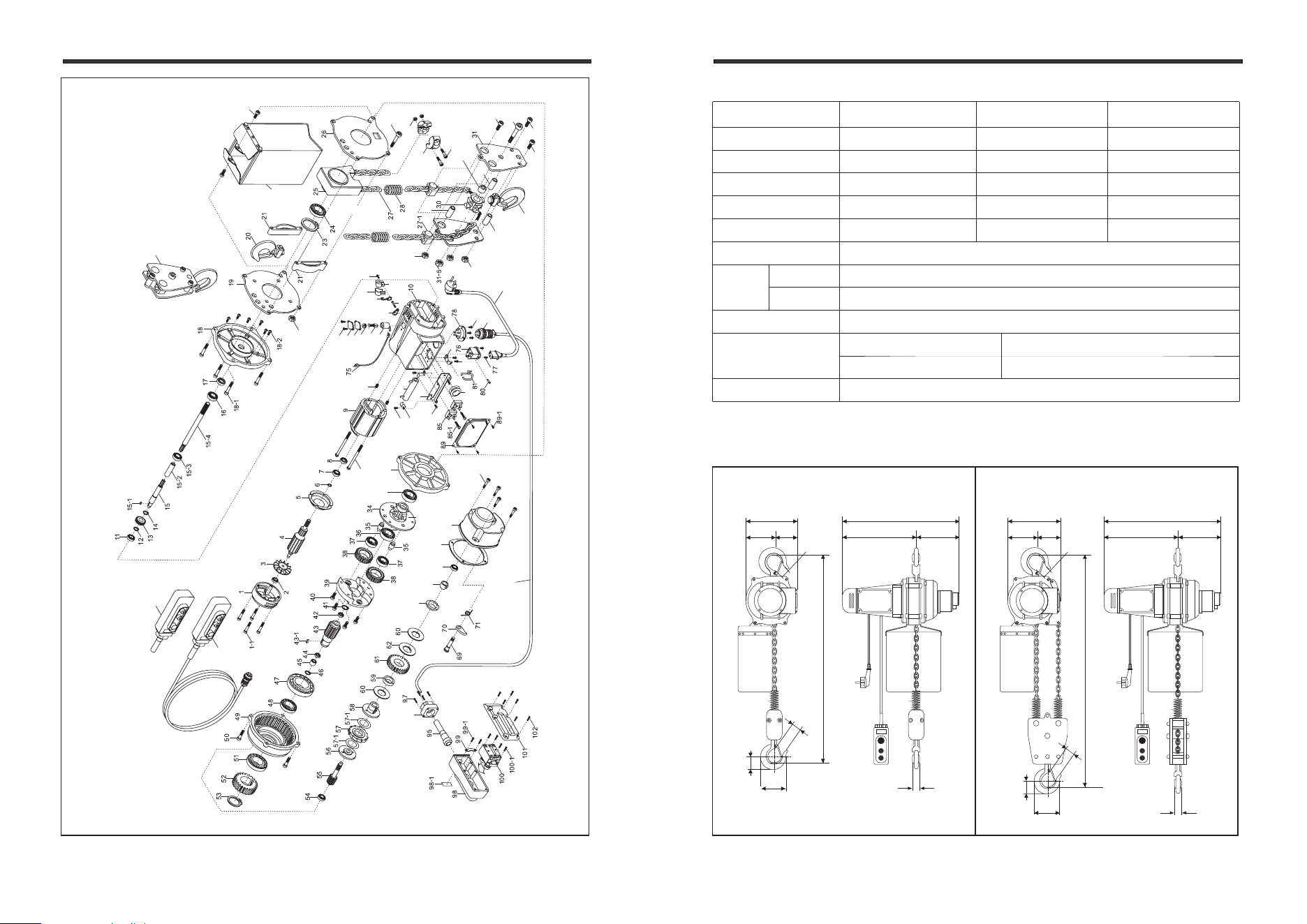
Model H2.5 H5 H10
Rated load 250kg 500kg 1000kg
Lifting height 3m 3m 3m
Chain size
6.3x19mm 6.3x19mm 6.3x19mm
Chain fall Single Single Double
Lifting speed 12m/min 6m/min 3m/min
Power supply Single-phase, 200-240V AC ( 50/60 Hz100-120V)
Motor
100-120V
200-240V
1300W 12A
1300W 6A
Hoist Body IP54
Switch IP65
Duty Cycle ED 25% Max.on time: 15 min/hr.Max. number of starts: 150/hr.
Ingress Protection
Insulation class F
13 2
1. Technical information
8. Spare parts drawing (H10)
1.1 Specifications
1.2 Dimentions
33
33-1
33-3
33-2
33-5
33-4
114
93
94
93-2
93-1
79
92-3
92-2
92-1
92
91
90
36-1
22
9-1
9-2
82
87
84
84-2
84-1
88
83
86
68
67
6665
63
64
32
72
31-7
31-8
31-7
115
96
73
29
29-2
29-1
31-9
31-2
31-3
31-6
31-6
31-1
31-4
18-3
18-4
Φ27mm
120mm
90mm
500mm
210mm
Φ27mm
45mm
85mm
450mm
16mm
250mm 200mm
450mm
250mm 200mm
16mm
H2.5,H5 H10
Φ27mm
120mm
90mm
500mm
210mm
Φ27mm
45mm
85mm
STOP STOP
2.1 Chain
2.3 Mounting Hoist
2.4 Electrical Connections
2.5 Pre-operational Checks and Trial Operation
2.6 Environmental Precaution
The following environmental conditions may result in the possible causes of
electric chain hoist trouble.
• Low temperature below -10° high temperature above 40°or humidity above
• In an organic chemistry or explosive power conditions.
90% conditions.
• In heavy acid or salty conditions.
• In the rain or snow condition.
• In a heavy general powder conditions.
2.2 Load Chain Lubrication
3 12
2. Pre-operational Procedures 8. Spare Parts Drawing (H2.5,H5)
Chain components including Buffering spring and Chain stop assemblies.
Never operate the hoist with incorrect, missing or damaged chain components.
Ensure that the suspension and the supporting structure are adequate to support
the hoist and its loads. Hook Mounted to a Fixed Location-Attach the hoist’s top
hook to the fixed suspension point. If necessary consult a professional that is
• Ensure that the voltage of the electric power supply is proper for the hoist.
• Before proceeding, ensure that the electrical supply for the hoist or trolley has
been de-energized (disconnected).
• Confirm the adequacy of the rated capacity for all slings, chains, wire ropes and
all other lifting attachments before use. Inspect all load suspension members for
damage prior to use and replace or repair all damaged parts.
• Ensure that the hoist is properly installed to either a fixed point, or trolley,
whichever applies
• If hoist is installed on a trolley, ensure that:
Trolley is properly installed on the beam, and stops for the trolley are correctly
positioned and securely installed on the beam.
• Ensure that all nuts, bolts and split pins (cotter pins) are sufficiently fastened.
• Check supply voltage before everyday use. If the voltage varies more than
10% of the rated value, electrical devices may not function normally.
• Before operating read and become familiar with Section 3 - Operation.
• Before operating ensure that the hoist (and trolley) meets the Inspection,
Testing and Maintenance requirements
• Before operating ensure that nothing will interfere with the full range of the hoist.
structure.
qualified to evaluate the adequacy of the suspension location and its supporting
• Always lubricate load chain weekly, or more frequently, depending
on severity of service.
• Always make sure to apply ISO VG 46 or 48 or equivalent machine oil.
Insufficient oil lubrication will accelerate Load Chain wear.
32
93-1
94
93-2
93
114
36-1
22
79
90
91
33
33-1
33-3
33-2
33-5
33-4
92
92-1
92-2
92-3
29
29-1
29-2
73
72
9-1
9-2
82
87
84
84-2
84-1
88
83
86
96
68
67
66
65
64
63
31-3
3.1 Introduction
3.2 Handling Precautions
• NOT lift more than rated load for the hoist.
• NOT work, walk or stand under an operating chain hoist
• NOT use the hoist to lift, support, or transport people.
• NOT lift loads over people.
• NOT attempt to lengthen the load chain or repair damaged load chain.
• NOT operate unless load is centered under hoist.
• NOT use hoist with twisted, kinked, damaged, or worn chain.
• NOT use the hoist in such a way that could result in shock or impact loads sheave.
• NOT use load chain as a sling or wrap load chain around load.
• NOT apply the load to the tip of the hook or to the hook latch.
• NOT allow the chain, or hook to be used as an electrical or welding ground.
• NOT operated beyond the limits of the load chain travel.
• Be familiar with operating controls, procedures.
• Make sure the unit is securely attached to a suitable support before applying load.
• Take up slack carefully and make sure load is balance.
• Make sure all persons stay clear of the supported load.
• Protect the hoist’s load chain from weld splatter or other damaging contaminants.
• Always look up when working around chain hoist, there is potential danger overhead.
• Warn personnel before lifting or moving a load.
• Warn personnel of an approaching load.
11 4
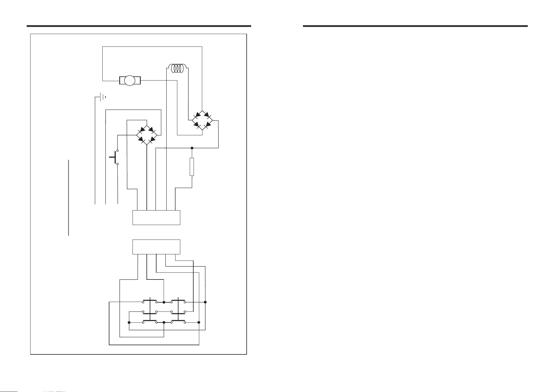
7. Wiring diagram 3. Operation
• Hoist operators shall be requited to read the operation section of this manul.
• Operator should also be trained in proper rigging procedures for the attachment
of loads to the hoist hook.
• Hoist operators should trained to be aware of potential malfunctions of
the equipment that require adjustment of repair and to be instructed to stop
operation if such malfunctions occur. and to immediately advise their supervisor
so corrective action can be taken.
• Hoist operators should have normal depth perception, field of vision, reaction
time, manual dexterity, and coordination.
R
Ar
L
1
2
3
4
5
Green
Yellow
White
Red
Input
Motor
Rotor
Bridge
Rectifier
Motor
Stator
Switch cord receptacle
1
2
3
4
5
Up
Down
Control Circuit
Push button switch
Resistor
Fuse
Earthing
ACV
Black
5 10
6. Trouble shootings
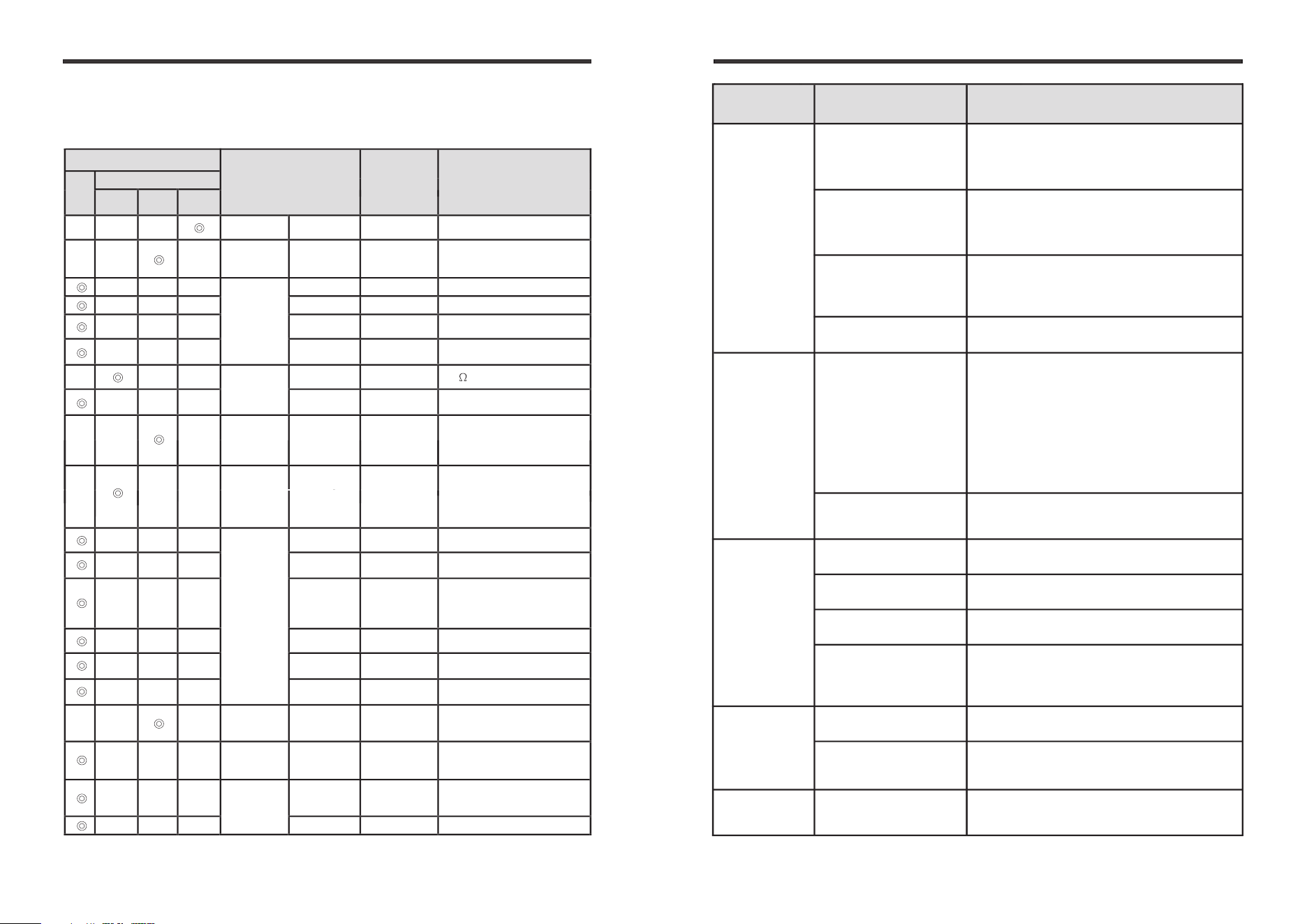
4. Inspection
Inspection Classification
Inspection Item
Inspection
Method
Inspection Reference
Daily
Periodical
One
month
Three
month
One
year
Marking
Label and the
like
Visual Existence of label
Installation
Functional
operating
mechanisms
Visual
To be properly adjusted and free
from unusual sounds when
operation
Control/
Switch
Working Function Reasonable actuation
Housing Visual To be free from cracks
Wiring Visual
To be free from remarkable
loose or damaged
Cord
Visual,
electricity
To be free from exposure of
conductive wire
Motor
Condition
of insulation
Measure with
resistance tester
1M min
Staining
damage
Decomposition
check
To be free from abnormalities
Braking
Wearing of
brake disc
Decomposition
check
To be free from remarkable wear
and damage
Gear
Damage ,
wearing
Decomposition
check
To be free from remarkable wear
and damage
Load Chain
elongation of
link length
Measure 5% minimum
Decreasing of
link diameter
Measure 8% of normal diameter max
Kink
phenomena
run-out of
foundation
Visual To be free from kink phenomena
Deforming or
corrosion
Visual To be free from abnormality
Lubrication
condition
Lubricating
The chain should be lubricated
every week for normal usage
Surface
condition
Visual
To be free from rust, nicks,
gouges, dents and weld splatter.
Sprocket /
Idle Sheave
Reeving function
Chain should be reeved properly
through sprocket and idle sheave
for double fall operation
Frame
Housing and
mechanical
components
Visual, function
To be free cracks, rupture
harmful deformation
Load Hook
Housing and
mechanical
components
Visual, function
To be free cracks, rupture and
harmful deformation by 5%
maximum
latch Visual To be free from deformed
Inspection should made by Initial inspection-prior to initial use, all new,
altered, or modified electric chain hoist, daily inspection and periodical
Inspection as the following table.
4.1 Inspection Classification
Possible cause Remedy
Proper installation of cap screw.
Replace resistor
Replace resistor
Replace motor
Clean carbon powder
Replace switch
Replace switch
Reduce load to within rated capacity
If abnormal operation or slippage occurs
do NOT attempt to disassemble or adjust
the mechanical load brake with friction
clutch. Replace the worn or malfunction
mechanical load brake with friction
clutch as an assembly with a new,
factory adjusted part.
Improper installation
of cap screw
Burnt resistor
Burnt resistor
Burnt motor
Accumulating too much
carbon powder on
carbon brush holder
Melted contact of switch
Malfunction of contact
of the switch
Hoist overloaded
Faulty friction clutch
Oil leakage
Having smell
or smoke
Short circuit
Hoist not
lift rated load
Symptom
Hoist lifts but
not low
Down circuit open
Broken conductor
in switch cord
Faulty switch
Check circuit for loose connectors.
Check down side of limit switch
for malfunction
Check the continuity for each conductor
in the cable. If one is broken, replace
entire cable.
Check electric continuity.
Check electrical connections
Replace or repair as needed.
Insect motor brush and replace it
if necessary
Brush wear
9 6
Before performing any trouble shooting on the electric chain hoist, de-energize
the supply of electricity as hazardous voltages are present in the electric chain hoist
and in connections between components.
Possible cause Remedy
Hoist
not operate
Loss of power
Hoist overloaded
Up circuit open
Broken conductor
in pendant cord
Check circuit breakers, switches, fuses
and connections on power cable.
Reduce load to within rated capacity
of hoist
Check circuit for loose connections.
Check up side of limit switch for
malfunction
Check the continuity of each conductor
in the cable. If one is broken, replace
entire cable.
Check voltage and frequency of power
supply against the rating on the
nameplate on motor.
Take a rest and perform the hoist
according
rated at 25%ED.
to its duty cycle percentage
Replace motor frame,stator, shaft,
armature and any other damaged parts.
Replace fuses
Insect motor brush and replace it
if necessary
Shut off power supply, check wiring
connection
inside push-button
on hoist control panel and
pendant.
Wrong voltage or
frequency
Motor overheated
Motor burned out
Fuses burned out
Brush wear
Improper, loose, or
broken wire in hoist
electric system
Symptom
5.1 Lubrication
Load chain■
Needle bearing of Low hook Idle sheave■
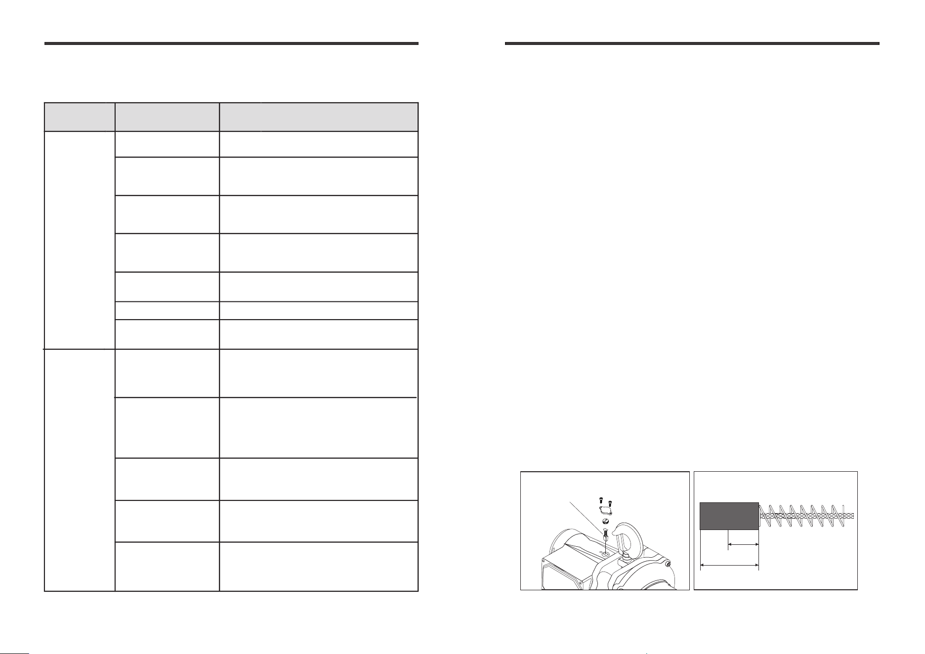
5.2 Carbon Brush Replacement
Clean the accumulated powder of carbon brush
to ascertain the insulation resistance
periodically
up to 1 MΩ.
● It is essential to check the carbon brush periodically. If its length is left
less than 7.5 mm resulting from wear, it is absolute necessary to replace
carbon brush immediately.
While replacing, smoothly insert carbon brush into carbon holder in ●
the first place, then put brush cap into the hole.
Before tightening the carbon brush holder, make sure to position O-ring. ●
A set of carbon brush consists 2 piece of carbon brush. Ascertain to replace●
2 pieces of carbon brush on opposite sides of winch body at the same time.
7.5
17
Carbon brush
carbon brush
● For longer lift, the load chain should be lubricated.
● The load chain lubrication should be accomplished after
cleaning the load chain with an acid free cleaning solution.
● The chain should be lubricated every 3 months.
Bearing should cleaned and lubricated at least once per year
for normal usage. Clean and lubricate more frequently for
heaver usage or severe conditions.
5. Maintenance and replacement
6. Trouble shootings
Check electrical continuity. Check
electrical connections. Replace or
repair as needed.
Repair by a qualified person trained
in repair of hoist and proper friction
clutch adjustment procedures.
Replace it as needed.
Faulty switch
in pendant
Faulty friction
clutch
Hoist lows
but not lift
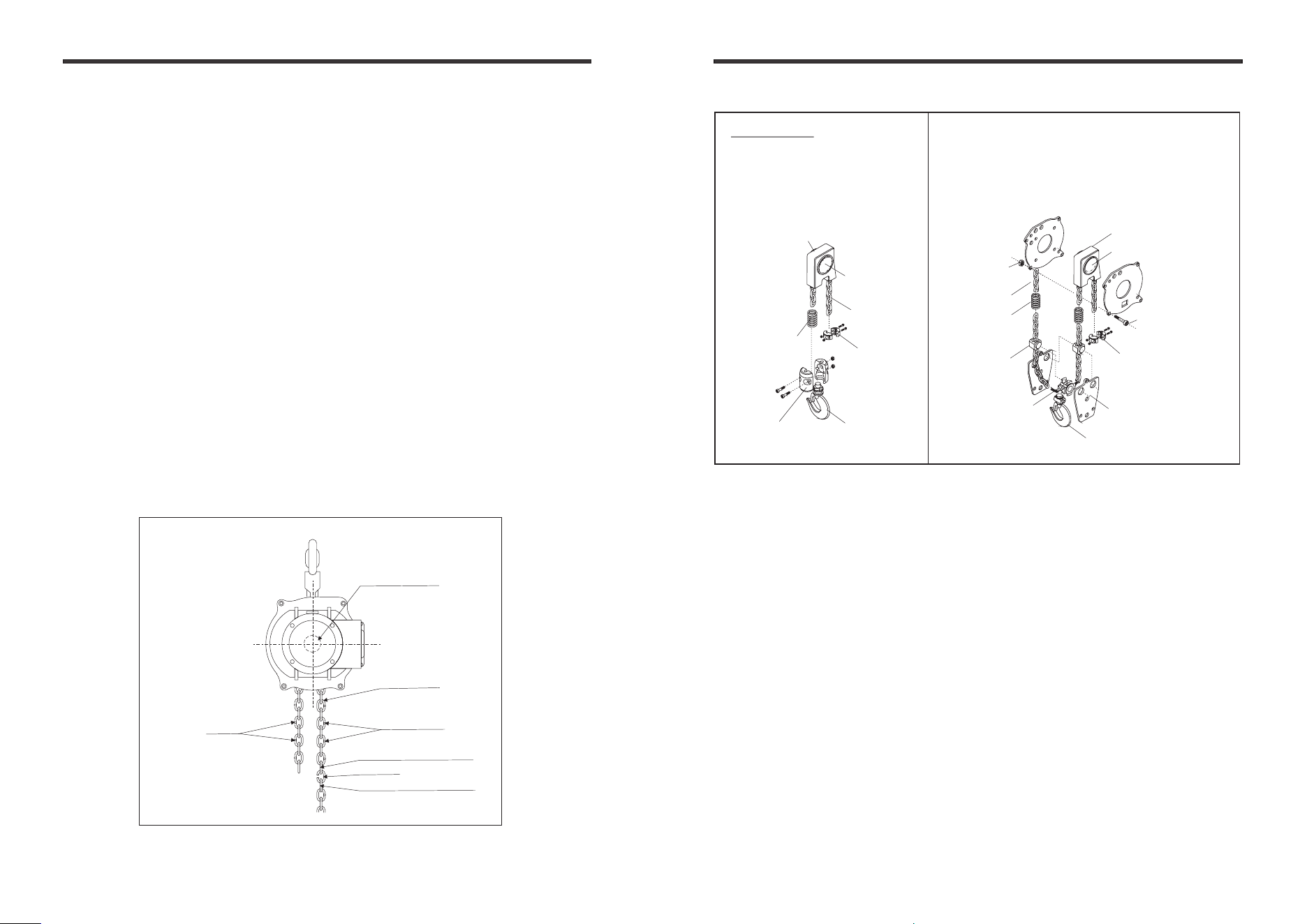
5.3 Load Chain Replacement 5.3 Load Chain Replacement
7 8
• Be sure that the replacement chain is the exact size, grade and
constructions as the original chain.
• The new load chain must have a an odd number links so that both its
end links have the same orientation.
• Destroy the old chain to prevent its reuse.
• When replacing load chain, check for wear on mating parts, such as
Load sheave and replace parts if necessary.
• Remove all chain components including bottom hook kit from the old
chain for reuse on new chain.
• Inspect and replace any damaged or worm parts.
• When replacing chain, pay an attention to chain weld side. Weld side
must be to outside. Refer to Dwg. 5.3-1
• Single fall operation: Using a C-link to attach the end link of new chain
and old chain.
then pass over the load sheave.
Refer to Dwg.5.3-1 and Dwg.5.3-2
• Double falls operation:
Using a C-link to attach the end link of new chain
and old chain. then pass over the load sheave and all remaining chain
components. Refer to Dwg.5.3-1 and Dwg. 5.3-2
• Make sure Chain stopper, Buffering spring, Chain guide, Chain anchorage,
Socket bolt, Locknut are properly installed.
• Operate the hoist down to move the chain through the hoist body, until
a sufficient amount of new chain is accumulated on the load side.
5.4 Mechanical Load Brake with Friction Clutch
Mech anic al Lo ad Bra ke wit h Fric tion C lut ch- If a bnor mal op eration o r
slippage occurs DO NOT attempt to disassemble or adjust the Mechanical
Loa d Br ak e wit h Fr ic tio n Cl ut ch. R ep lace th e wo rn or m al fu nct io ni ng
mechanical Brake with Friction Clutch as an assembly with a new one which
factory adjusted part.
5.5 Fuses
5.6 Outdoor Installation
The fuses size -main fuses rating (Amps) 10
• The storage location should be clean and dry.
For hoist installations that are outdoors, the hoist should be covered
when not in use.
•
• Possible of corrosion on components of the hoist increases for installations
where salt air and high humidity are present. Make frequent and regular
inspections of the unit’s condition and operation.
5. Maintenance and replacement
5. Maintenance and Replacement
Single fall (H2.5, H5) Double falls(H10)
Load Chain
Load Sheave
Load sheave
Chain Stopper
Lower Hook Holder
Lower Hook
Buffering Spring
Chain Guide House
Chain Guide house
Idle Sheave
Buffering Spring
Load Chain
Chain Guide
Chain Stopper
Chain Anchorage
Lock Nut
Lower Hook
Load Sheave
Load Chain
(Load Side)
Weld
Old chain end link
C-link
New chain end link
Weld
Lower Hook Holder
Dwg. 5.3-1
Dwg. 5.3-2