GHP
™
10 Mercury
®
Verado
®
Adapter Kit Installation Instructions
To use the GHP 10 autopilot system with Mercury Verado engines, you must install the GHP 10 Mercury Verado Adapter Kit. Use the GHP 10
Installation Instructions (supplied with the GHP 10 autopilot system) and these installation instructions to install the GHP 10 autopilot system on
your Mercury Verado-equipped boat.
Installing the GHP 10 Autopilot System
The GHP 10 Installation Instructions explain the installation procedures to install the GHP 10 autopilot system, but the instructions do not cover
the specic Mercury Verado hydraulic and tachometry connections (J Box Adapter Plug or Plugs).
Pages 2–6 contain Mercury Verado-specic instructions on installing the GHP 10 in the hydraulic system.
For instructions on installing the check valve assembly, see page 8.
For instructions on installing the return hose and tting kit, see page 8.
For instructions on connecting the GHP 10 tachometer wiring to the Mercury J Box adapter plugs, see page 9.
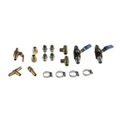
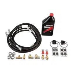
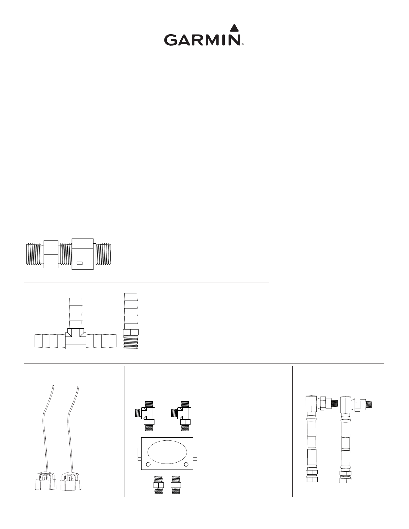
Package Contents
• Hose Kit
◦ 5 ft. (1.5 m) hose with 4-ORFS female ttings (1)
◦ 4 ft. (1.2 m) hose with 4-ORFS female ttings (1)
◦ 1 ft. (0.3 m ) hose with 4-ORFS female ttings (1)
• Return Hose
◦ 3/8 in. (9 mm) ID 6 ft.
(1.8 m) hose (1)
◦ Hose clamps (4)
• Mercury Synthetic Power-Steering uid
• Ferrite Beads (4)
• Shadow Drive ttings
◦ 4-ORFS male to 1/4”
NPT (1)
◦ 1/4” NPT male to 1/4”
NPT female (1)
• Return Hose Fitting Kit
◦ T-tting with 3/8 in.
(9 mm) barbs for
return hose (1)
◦ Barbed return tting
for pump end (1)
• Tachometer to J Box adapter plug
(2)
• Check Valve Assembly kit
(sold separately - 1.2 L
pump only)
p/n: 010-11203-00
• 1/4 in. (6 mm) NPT male to
1/4 in. (6 mm) NPT female
90-degree ttings (2)
• 17 in. (0.4 m) cable tie wrap
(1)
• Cable tie mount (1)
• #8 x 5/8 (16 mm) stainless
steel screw
• Isolation Hose kit (sold
separately - 1.2 L pump only)
p/n: 010-11204-00
December 2011 190-00894-04 Rev. C Printed in USA
2 GHP 10 Mercury Verado Adapter Kit Installation Instructions
Installing the GHP 10 in a Mercury Verado Hydraulic System
Notice
Before starting the hydraulic installation, verify the type of hydraulic steering in the boat. If the hydraulic steering in your boat does not match
any of the diagrams in this document, consult Garmin Product Support for specic installation procedures.
Because of the Mercury pump module, additional steps must be taken when installing the GHP 10 pump and shadow drive valve. Consult the
hydraulic layout diagrams in this document to determine the best location to install the pump and shadow drive valve in the hydraulic system of
your boat.
NOTE: If you are installing a 1.2 L pump in the hydraulic system, you must purchase the check valve assembly kit and isolation hose kit (sold
separately) to ensure a proper hydraulic installation. For more information on the check valve assembly and isolation hose kits, see page 8.
1.2 L (p/n: 010-11098-00) Pump Hydraulic Diagrams
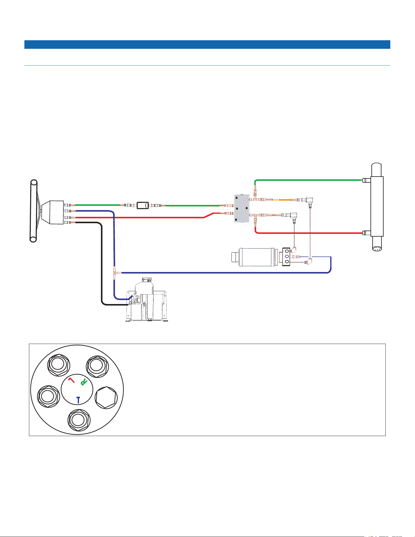
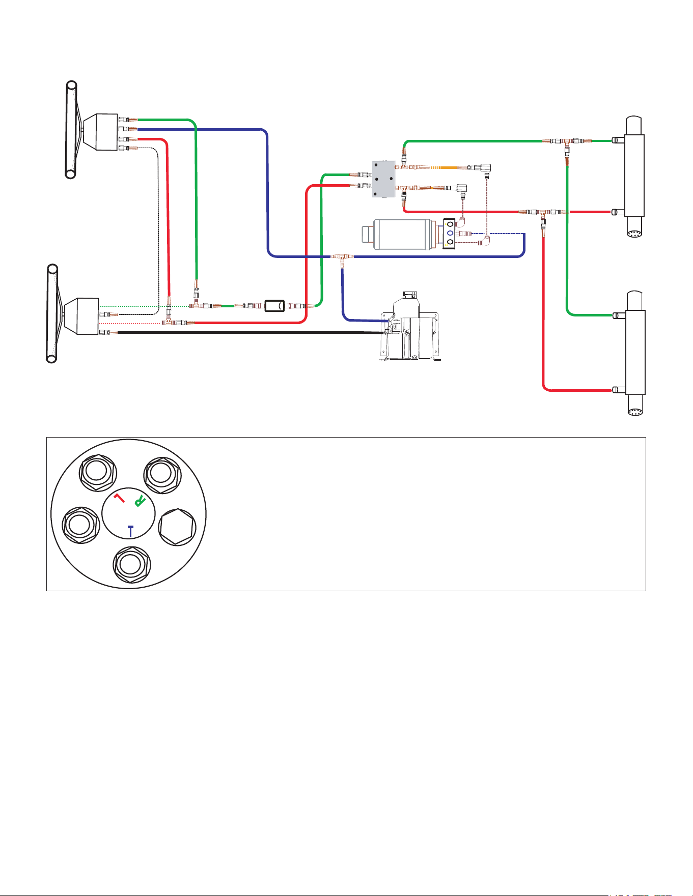
Installing a 1.2 L Pump in a Single-Helm Verado Hydraulic System
NOTE: Components in the diagram connected by dotted lines are directly connected to each other.
L
T
R
P
C2
C1
V1
V2
Mercury Steering
Cylinder Assembly
Mercury pump module
Port
Starboard
Return
High-pressure line
DO NOT CUT
1.2 L pump
Check valve
(sold separately)
see page 8
Port
Starboard
Isolation hoses
See below for helm
connection details
Shadow Drive valve
E
R
T
P
L
R
T
P
L
E
R—Hose to the starboard side of the steering cylinder or cylinders
T—Hose to the tank of the Mercury pump module
L—Hose to the port side of the steering cylinder or cylinders
P—High-pressure supply hose from the Mercury pump module. Do not remove or cut this hose.
E—Plug. Do not remove.
Helm Hose-Connection Assignments
Important Notes
• Do not cut or remove the high-pressure hydraulic hose that connects to the “P” connector on the helm.
• Install the shadow drive valve horizontally, as level as possible.
• Install the shadow drive valve in either the port or starboard hydraulic line.
• Do not install a tee tting between the helm and the shadow drive valve.
• Do not install the shadow drive valve directly onto the helm; install a length of hydraulic hose between the helm and the shadow drive valve.
GHP 10 Mercury Verado Adapter Kit Installation Instructions 3
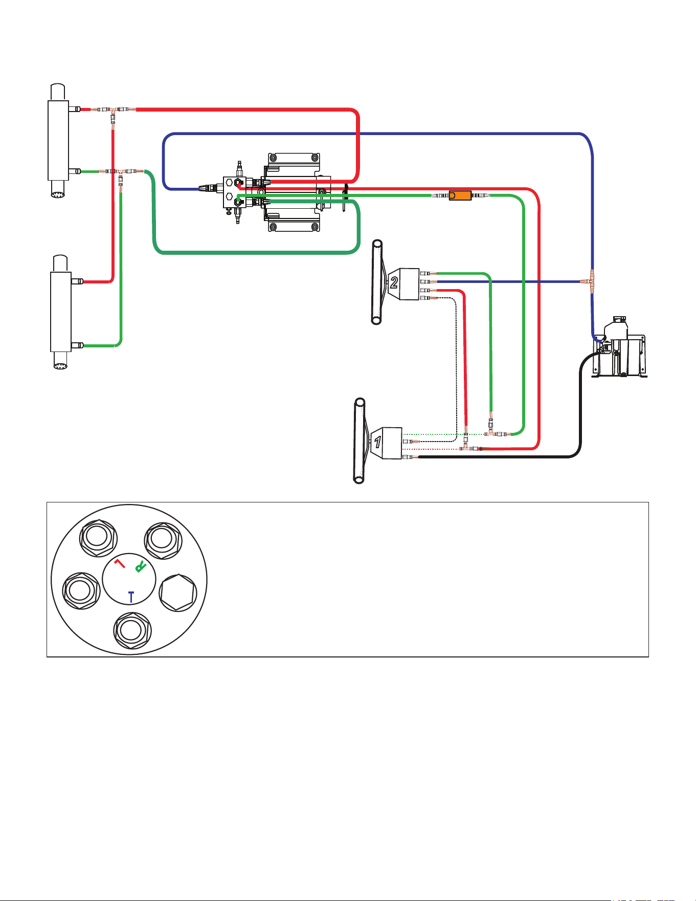
Installing a 1.2 L Pump in a Dual-Helm Verado Hydraulic System
NOTE: Components in the diagram connected by dotted lines are directly connected to each other.
High-pressure line
DO NOT CUT
L
T
R
P
2
1
L
T
R
P
C2
C1
V1
V2
High-pressure line
DO NOT CUT
Mercury pump module
Starboard
Port
Mercury Steering
Cylinder Assembly
Mercury Steering
Cylinder Assembly
1.2 L pump
Isolation hoses
Check valve
(sold separately)
see page 8
Port
Starboard
Return
See below for helm
connection details
Shadow
Drive
valve
Upper helm
Lower helm
E
R
T
P
L
R
T
P
L
E
R—Hose to the starboard side of the steering cylinder or cylinders
T—(Upper helm) Hose to the tank of the Mercury pump module
T—(Lower helm) High-pressure supply hose to the upper helm. Do not remove or cut this hose.
L—Hose to the port side of the steering cylinder or cylinders
P—(Upper helm) High-pressure supply hose from the lower helm. Do not remove or cut this
hose.
P—(Lower helm) High-pressure supply hose from the Mercury pump module. Do not remove or
cut this hose.
E—Plug. Do not remove.
Helm Hose-Connection Assignments
Important Notes
• Do not cut or remove the high-pressure hydraulic hose that connects to the “P” connector on the upper helm or the “P” or “T” connectors on
the lower helm.
• Install the shadow drive valve horizontally, as level as possible.
• Install the shadow drive valve in either the port or starboard hydraulic line.
• Install the shadow drive valve between the tee tting that connects the helms and the check valve to ensure that both helms activate the
shadow drive valve.
• Do not install the shadow drive valve directly onto the helm or tee tting that connects the helms; install a length of hydraulic hose between
the helm or tee tting and the shadow drive valve.
4 GHP 10 Mercury Verado Adapter Kit Installation Instructions
Legacy 2.1 L (p/n: 010-11099-00) Pump Hydraulic Diagrams
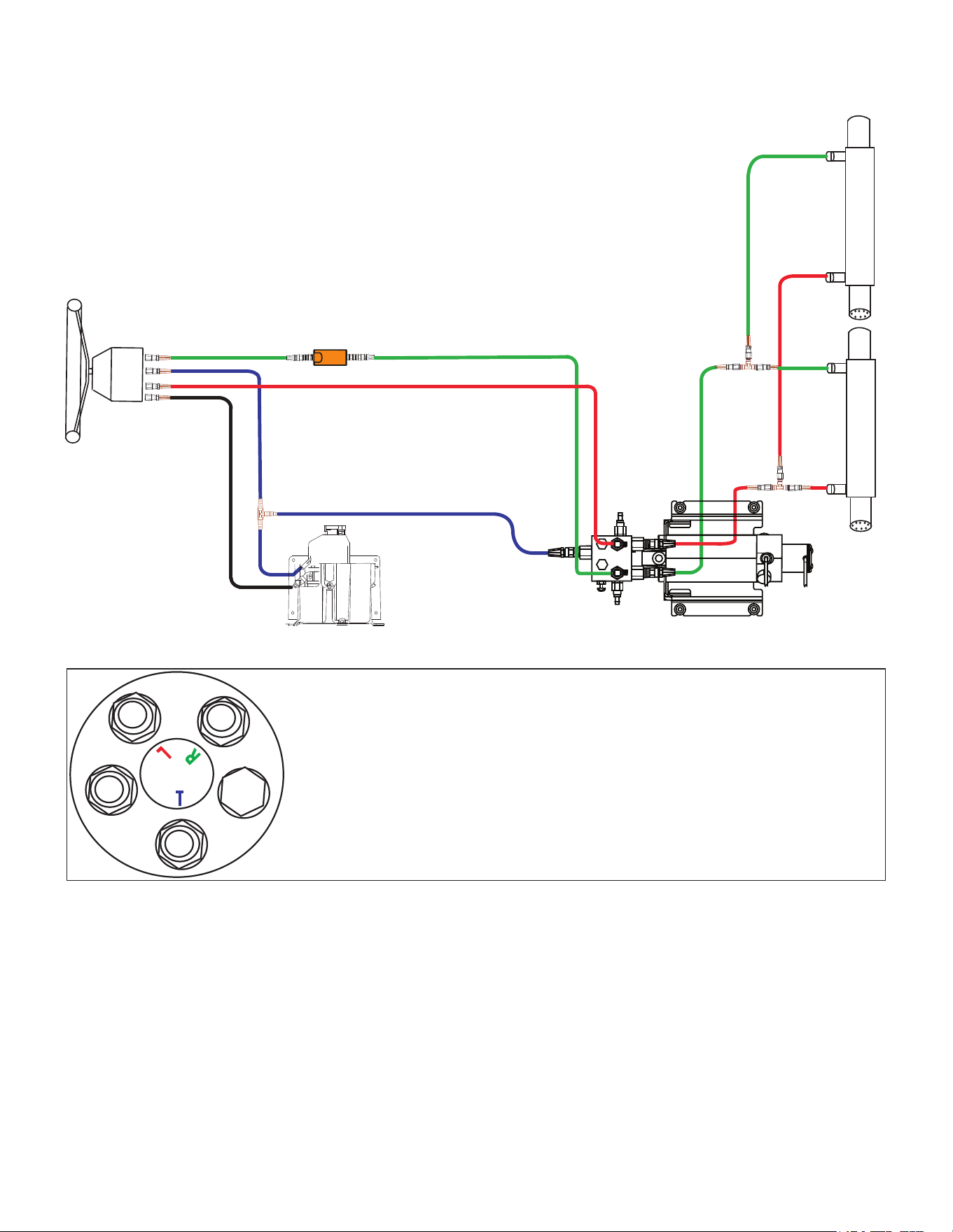
Installing a Legacy 2.1 L Pump in a Single-Helm Verado Hydraulic System
Legacy 2.1 L
pump
Mercury pump module
Port
Starboard
Return
High-pressure line
DO NOT CUT
Shadow Drive valve
Port
Starboard
Mercury Steering
Cylinder Assembly
E
R
T
P
L
R
T
P
L
E
R—Hose to the starboard side of the steering cylinder or cylinders
T—Hose to the tank of the Mercury pump module
L—Hose to the port side of the steering cylinder or cylinders
P—High-pressure supply hose from the Mercury pump module. Do not remove or cut this hose.
E—Plug. Do not remove.
Helm Hose-Connection Assignments
Important Notes
• Do not cut or remove the high-pressure hydraulic hose that connects to the “P” connector on the helm.
• Install the shadow drive valve horizontally, as level as possible.
• Install the shadow drive valve in either the port or starboard hydraulic line.
• Do not install the shadow drive valve directly onto the helm; install a length of hydraulic hose between the helm and shadow drive valve.
GHP 10 Mercury Verado Adapter Kit Installation Instructions 5
Installing a Legacy 2.1 L Pump in a Dual-Helm Verado Hydraulic System
NOTE: Components in the diagram connected by dotted lines are directly connected to each other.
Legacy 2.1 L
pump
Port
Starboard
Mercury Steering
Cylinder Assembly
Mercury Steering
Cylinder Assembly
Mercury pump module
Port
Starboard
Return
Shadow
Drive
valve
High-pressure line
DO NOT CUT
Upper helm
Lower helm
High-pressure line
DO NOT CUT
E
R
T
P
L
R
T
P
L
E
R—Hose to the starboard side of the steering cylinder or cylinders
T—(Upper helm) Hose to the tank of the Mercury pump module
T—(Lower helm) High-pressure supply hose to the upper helm. Do not remove or cut this hose.
L—Hose to the port side of the steering cylinder or cylinders
P—(Upper helm) High-pressure supply hose from the lower helm. Do not remove or cut this
hose.
P—(Lower helm) High-pressure supply hose from the Mercury pump module. Do not remove or
cut this hose.
E—Plug. Do not remove.
Helm Hose-Connection Assignments
Important Notes
• Do not cut or remove the high-pressure hydraulic hose that connects to the “P” connector on the upper helm or the “P” or “T” connectors on
the lower helm.
• Install the shadow drive valve horizontally, as level as possible.
• Install the shadow drive valve in either the port or starboard hydraulic line.
• Install the shadow drive valve between the tee tting that connects the helms and the GHP pump to ensure that both helms activate the
shadow drive valve.
• Do not install the shadow drive valve directly onto the helm or tee tting that connects the helms; install a length of hydraulic hose between
the helm or tee tting and the shadow drive valve.
6 GHP 10 Mercury Verado Adapter Kit Installation Instructions
Compact 2.1 L (p/n: 010-11099-10) Pump Hydraulic Diagrams
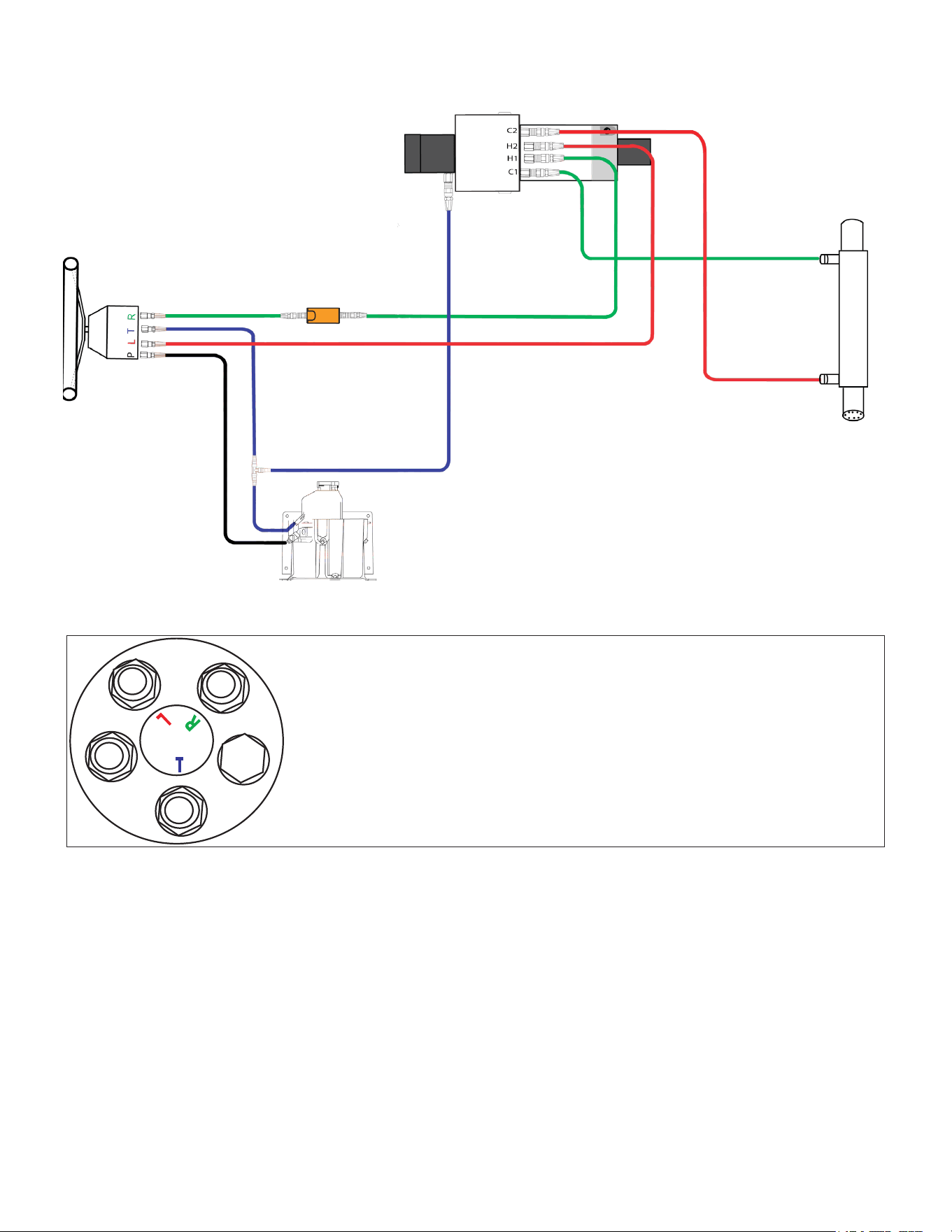
Installing a Compact 2.1 L Pump in a Single-Helm Verado Hydraulic System
L
T
R
P
H1
H2
Compact 2.1 L
pump
Mercury pump module
Port
Starboard
Return
High-pressure line
DO NOT CUT
Shadow Drive valve
Port
Starboard
Mercury Steering
Cylinder Assembly
See below for helm
connection details
Mercury Steering
Cylinder Assembly
E
R
T
P
L
R
T
P
L
E
R—Hose to the starboard side of the steering cylinder or cylinders
T—Hose to the tank of the Mercury pump module
L—Hose to the port side of the steering cylinder or cylinders
P—High-pressure supply hose from the Mercury pump module. Do not remove or cut this hose.
E—Plug. Do not remove.
Helm Hose-Connection Assignments
Important Notes
• Do not cut or remove the high-pressure hydraulic hose that connects to the “P” connector on the helm.
• Install the shadow drive valve horizontally, as level as possible.
• Install the shadow drive valve in either the port or starboard hydraulic line.
• Do not install the shadow drive valve directly onto the helm; install a length of hydraulic hose between the helm and the shadow drive valve.
GHP 10 Mercury Verado Adapter Kit Installation Instructions 7
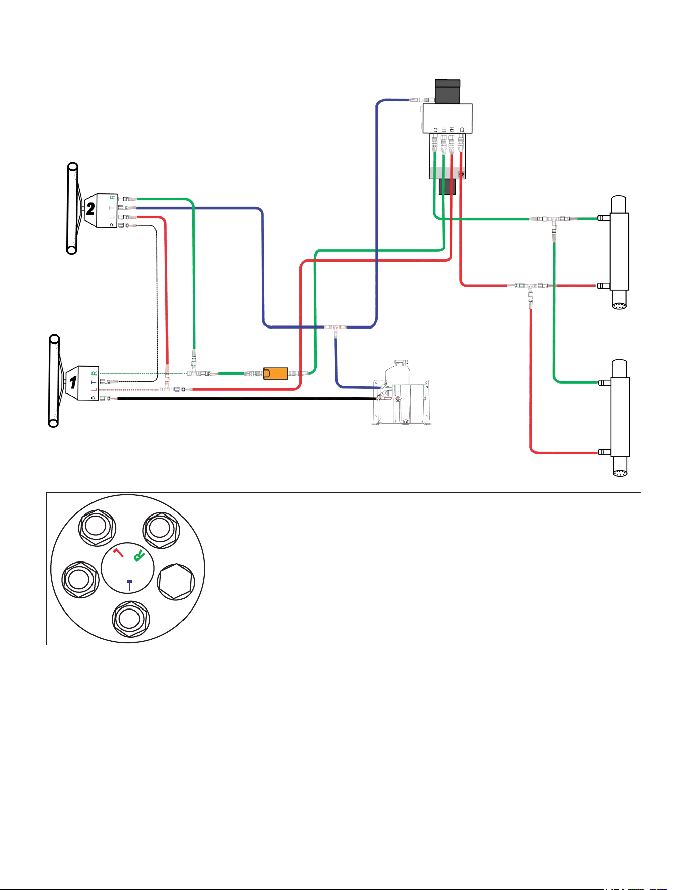
Installing a Compact 2.1 L Pump in a Dual-Helm Verado Hydraulic System
NOTE: Components in the diagram connected by dotted lines are directly connected to each other.
High-pressure line
DO NOT CUT
1
L
T
R
P
L
T
R
P
2
H1
H2
Compact 2.1 L
pump
Mercury
pump
module
Port
Starboard
Return
High-pressure line
DO NOT CUT
Shadow Drive valve
Port
Starboard
Mercury Steering
Cylinder Assembly
See below for helm
connection details
Mercury Steering
Cylinder Assembly
Upper helm
Lower helm
Return
E
R
T
P
L
R
T
P
L
E
R—Hose to the starboard side of the steering cylinder or cylinders
T—(Upper helm) Hose to the tank of the Mercury pump module
T—(Lower helm) High-pressure supply hose to the upper helm. Do not remove or cut this hose.
L—Hose to the port side of the steering cylinder or cylinders
P—(Upper helm) High-pressure supply hose from the lower helm. Do not remove or cut this
hose.
P—(Lower helm) High-pressure supply hose from the Mercury pump module. Do not remove or
cut this hose.
E—Plug. Do not remove.
Helm Hose-Connection Assignments
Important Notes
• Do not cut or remove the high-pressure hydraulic hose that connects to the “P” connector on the upper helm or the “P” or “T” connectors on
the lower helm.
• Install the shadow drive valve horizontally, as level as possible.
• Install the shadow drive valve in either the port or starboard hydraulic line.
• Install the shadow drive valve between the tee tting that connects the helms and the GHP pump to ensure that both helms activate the
shadow drive valve.
• Do not install the shadow drive valve directly onto the helm or tee tting that connects the helms; install a length of hydraulic hose between
the helm or tee tting and the shadow drive valve.
8 GHP 10 Mercury Verado Adapter Kit Installation Instructions
Installing the Check Valve and Isolation Hoses
The check valve and isolation hoses are required when installing the GHP 10 with a 1.2 liter pump to a Verado single- or dual-helm hydraulic
system. It is recommended that you install the check valve and isolation hoses on the pump before installing the pump in your boat.
For this installation, you will need the following:
• 1.2 L pump
• Check valve assembly
• Cable tie mount
• Isolation hoses
• Thread sealant (Loctite® Pro Lock Tight® multipurpose anaerobic gel, part number 51604 or equivalent)
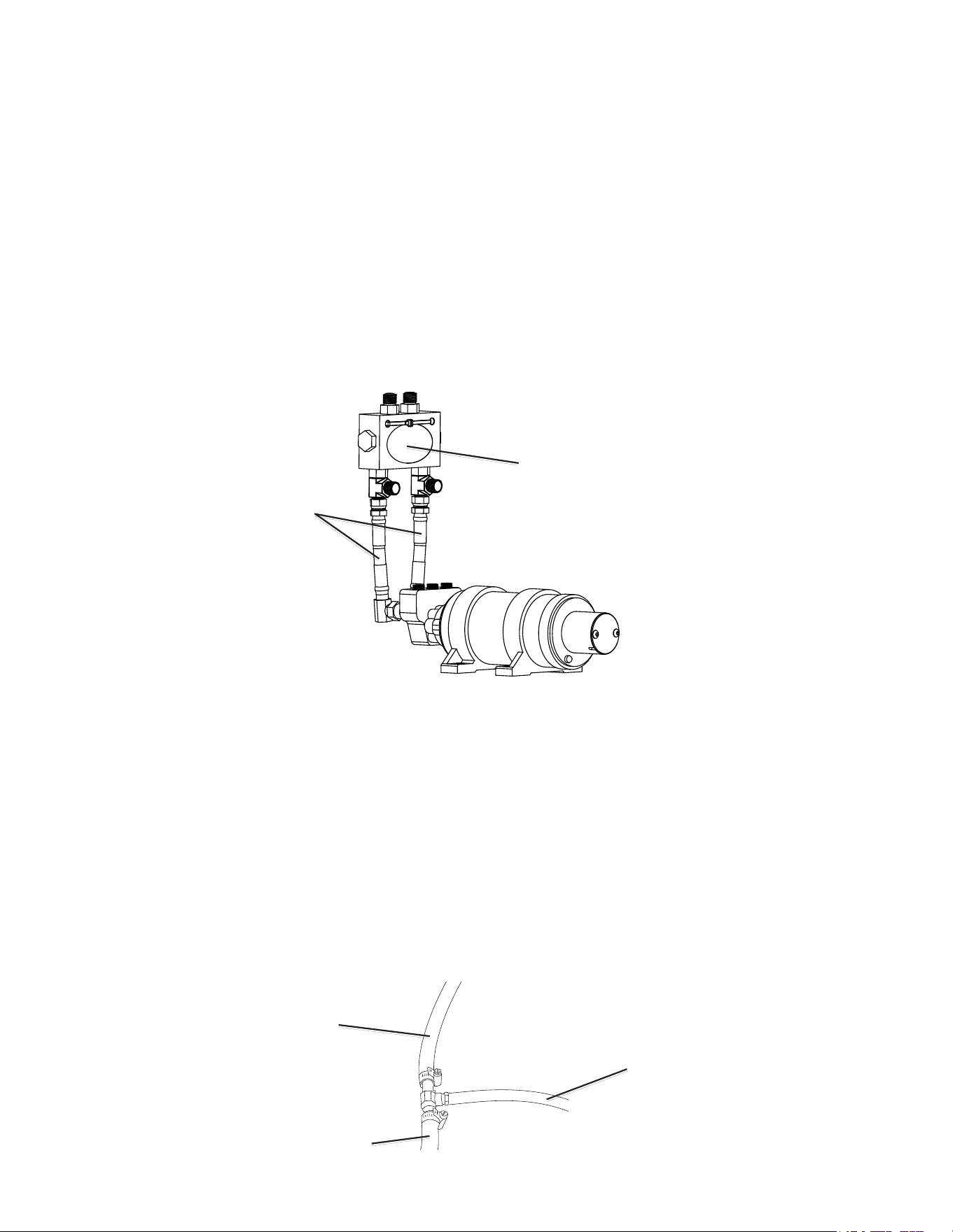
Installing the Check Valve and Isolation Hoses on the 1.2 L Pump
Do not use Teon tape on any hydraulic tting. Use an appropriate thread sealant such as Loctite Pro Lock Tight multipurpose anaerobic gel,
part number 51604, or equivalent, on all pipe threads in the hydraulic system.
To install the check valve and isolation hoses on the 1.2 L pump in vertical orientation:
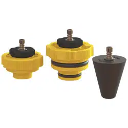
1. Install the isolation hoses and check valve assembly to the GHP pump as shown in the illustration.
Isolation hoses
Check valve
2. Mount the pump according to the instructions included with the unit.
3. Mount the cable tie mount to the surface to which you will secure the check valve.
4. Attach the check valve to the cable tie mount using the cable tie.
Installing the Return Hose and Fitting Kit
The low pressure return hydraulic hose from the helm (upper helm only in dual-helm installations) to the Mercury pump module must be
branched to run to the GHP pump as well. For this installation, you need the following:
• Return hose and clamps
• Return hose tting kit
To install the return hose:
1. Cut the return hose in an appropriate location to add the branch to the GHP pump.
2. Install the tee tting in the cut return hose and securely clamp the connections, as shown in the illustration.
3. Install the return hose on the remaining end of the tee tting and securely clamp the connection, as shown in the illustration.
To Mercury pump
To Helm
To GHP pump
GHP 10 Mercury Verado Adapter Kit Installation Instructions 9
4. Screw the threaded end of the barbed/threaded tting into the appropriate location on the GHP pump. Use an appropriate thread sealant
such as Loctite Pro Lock Tight multipurpose anaerobic gel, part number 51604, or equivalent, on the threads.
5. Install the remaining free end of the return hose to the barbed tting on the GHP pump.
Installing the Mercury J Box Adapter Plug
The Mercury J Box adapter plug must be used when installing the GHP 10 in a Mercury Verado-equipped boat. Failure to use the adapter plug
can void the warranty of both the GHP 10 and the Mercury Verado motor.
To install the Mercury J Box adapter plug:
1. Connect the GHP 10 CCU positive (+) tachometer wire to the adapter plug wire.
2. Install the adapter plug into the Mercury Verado junction box.
3. Connect the GHP 10 CCU negative (-) tachmometer wire to ground.
Use the following table to identify the appropriate wires on the GHP 10 and the Mercury J Box Adapter Plug or Plugs:
Engine Conguration GHP 10 to J Box Adapter Plug GHP 10 to Ground
Single engine Green and violet (twist together) White and gray (twist together)
Dual engines Port engine = violet Gray
Starboard engine = green White
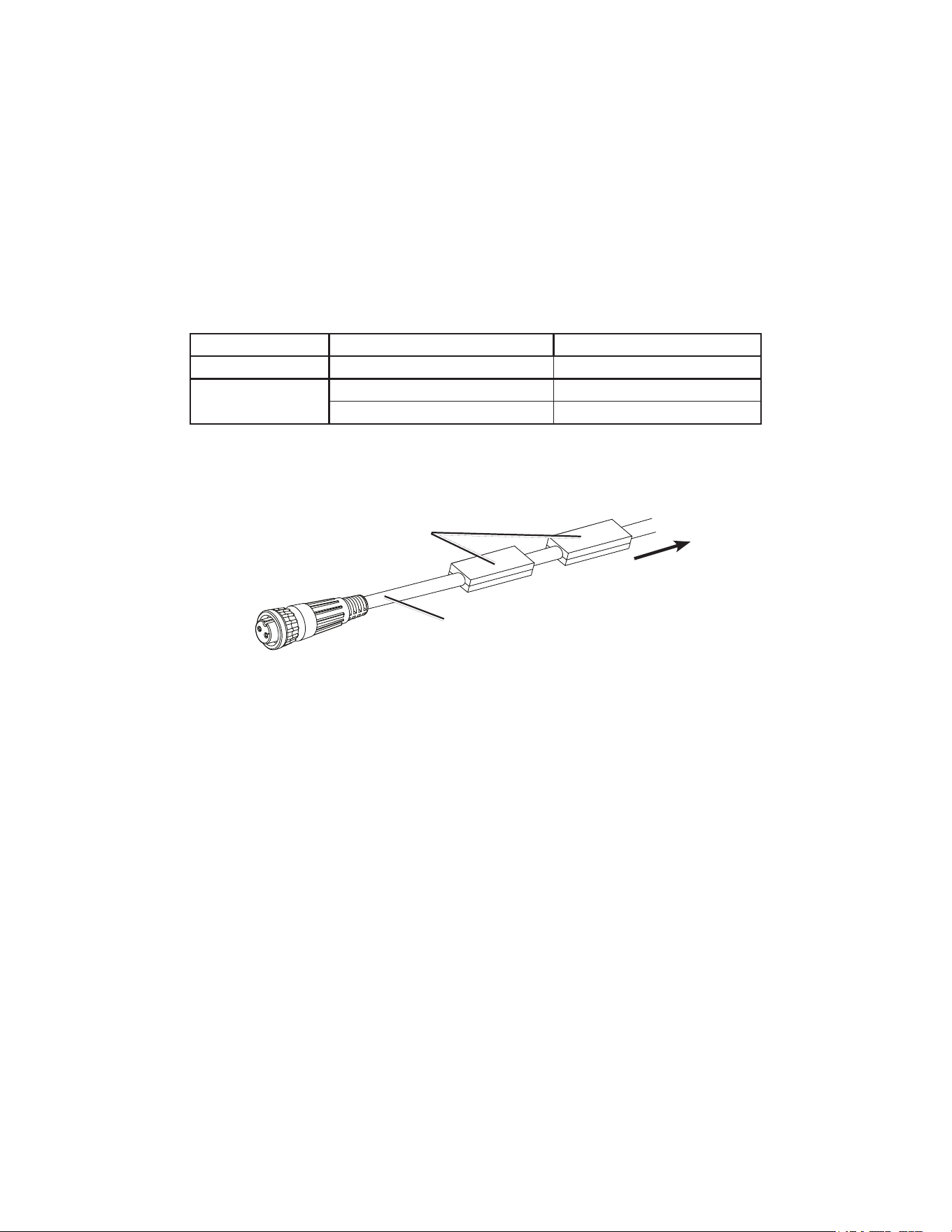
Installing the Ferrite Beads on the ECU Power Cable
Install two of the four included ferrite beads on the ECU power cable of the GHP 10 Autopilot system. Install the ferrite beads closer to the ECU
than to the battery.
Ferrite beads
To the battery
ECU power cable
Open the ferrite beads and snap them closed around the power cable as shown in the illustration.

For the latest free software updates (excluding map data) throughout the life of your Garmin products, visit the Garmin Web
site at www.garmin.com.
© 2008 Garmin Ltd. or its subsidiaries
Garmin International, Inc.
1200 East 151
st
Street, Olathe, Kansas 66062, USA
Garmin (Europe) Ltd.
Liberty House, Hounsdown Business Park, Southampton, Hampshire, SO40 9LR UK
Garmin Corporation
No. 68, Zhangshu 2
nd
Road, Xizhi Dist., New Taipei City, 221, Taiwan (R.O.C.)
www.garmin.com