MERCURY
®
VERADO
®
REACTOR
™
ADAPTER KIT
INSTALLATION INSTRUCTIONS
Getting Started
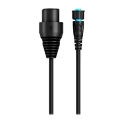
To use a Garmin
®
Reactor SmartPump autopilot system with Mercury Verado engines, you must also install
components provided in this kit. For proper installation, you must use these instructions, along with the
instructions provided in the autopilot corepack.
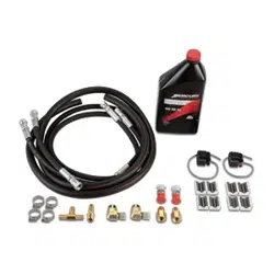
Package Contents
Hose clamps (4)
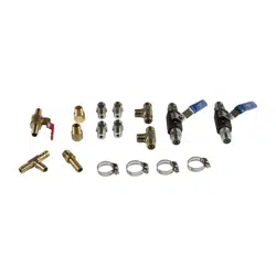
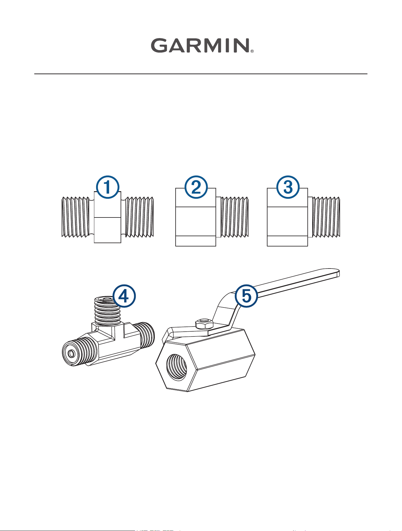
High-pressure hydraulic fittings:
GUID-1B77E4DC-684E-484B-9824-B62A28964155 v2November 2018
1
/
4
in. ORFS male to
1
/
4
in. NPT male (8)
Two for the Shadow Drive
™
sensor, two for the SmartPump manifold, and four as an option for the ORFS
shut-off ball valves.
1
/
4
in. NPT male to
1
/
4
in. NPT female (2) (for the Shadow Drive sensor)
1
/
4
in. NPT male to
1
/
4
in. ORFS female (2) (option for the ORFS shut-off ball valves)
ORFS T-fitting (2)
ORFS shut-off ball valve (2)
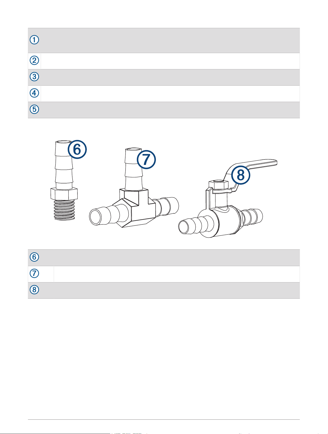
Low-pressure (return hose) fittings:
Barbed return fitting for pump connector
T-fitting with
3
/
8
in. (9 mm) barbs for return hose
Barbed shut-off-valve
Tools Needed
• Safety glasses
• Wrenches
• Hydraulic tools
• Phillips and flat screwdrivers
• Marine sealant
• Thread sealant, such as Loctite
®
567
• Hydraulic hose
• Mercury steering fluid
2

Hydraulic Layouts
NOTICE
If the steering system in your boat does not match any of the hydraulic layouts in this manual and you are
unsure how to install the pump, contact Garmin Product Support.
Before you start the pump installation, identify the type of hydraulic steering system in your boat. Each boat is
different, and you must consider certain aspects of the existing hydraulic layout before deciding where to mount
the pump.
Before you start the pump installation, you should throughly review the hydraulic considerations for important
information on hydraulic hose and fitting types, installation methods, and thread-sealant information.
Hydraulic Layout Important Considerations
Because the Mercury pump module is present in the Verado steering system, you must take additional steps
when installing the autopilot pump and Shadow Drive sensor. Consult the hydraulic layout diagrams in this
document to determine the best location to install the pump and Shadow Drive sensor in the hydraulic system
of your boat.
This kit includes the fittings and valves needed to connect the autopilot pump to the system, but does not
include the hydraulic hose. You must supply the appropriate hydraulic hose to fit the needs of your installation.
When planning the autopilot installation, observe the following considerations:
• You must not cut or remove the high-pressure hydraulic hose that connects to the “P” connector on the upper
helm or the "P" or "T" connectors on the lower helm.
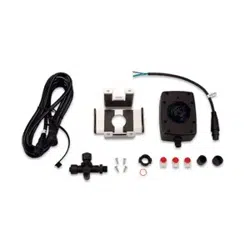
• You must install the Shadow Drive sensor horizontally, as level as possible.
• You can install the Shadow Drive sensor in either the port or starboard hydraulic line.
• You must not connect the Shadow Drive sensor directly onto the helm. You must install a length of hydraulic
hose between the helm and the Shadow Drive sensor.
• On a dual-helm boat, the Shadow Drive sensor should be located between the T-fitting that connects the
helms and the pump, so that both helms activate the Shadow Drive sensor.
• On a single-helm boat, there should not be a T-fitting between the helm and the Shadow Drive sensor.
3
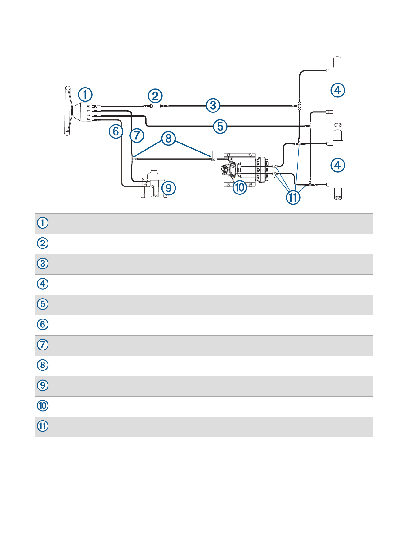
Single-Helm Layout Diagram
Helm
Shadow Drive sensor
Starboard line
Steering cylinder
Port line
High-pressure line (do not remove or cut)
Low-pressure return line
Barbed T-connector and shutoff valve
Mercury pump module
SmartPump
Threaded T-connectors and shutoff valves
4
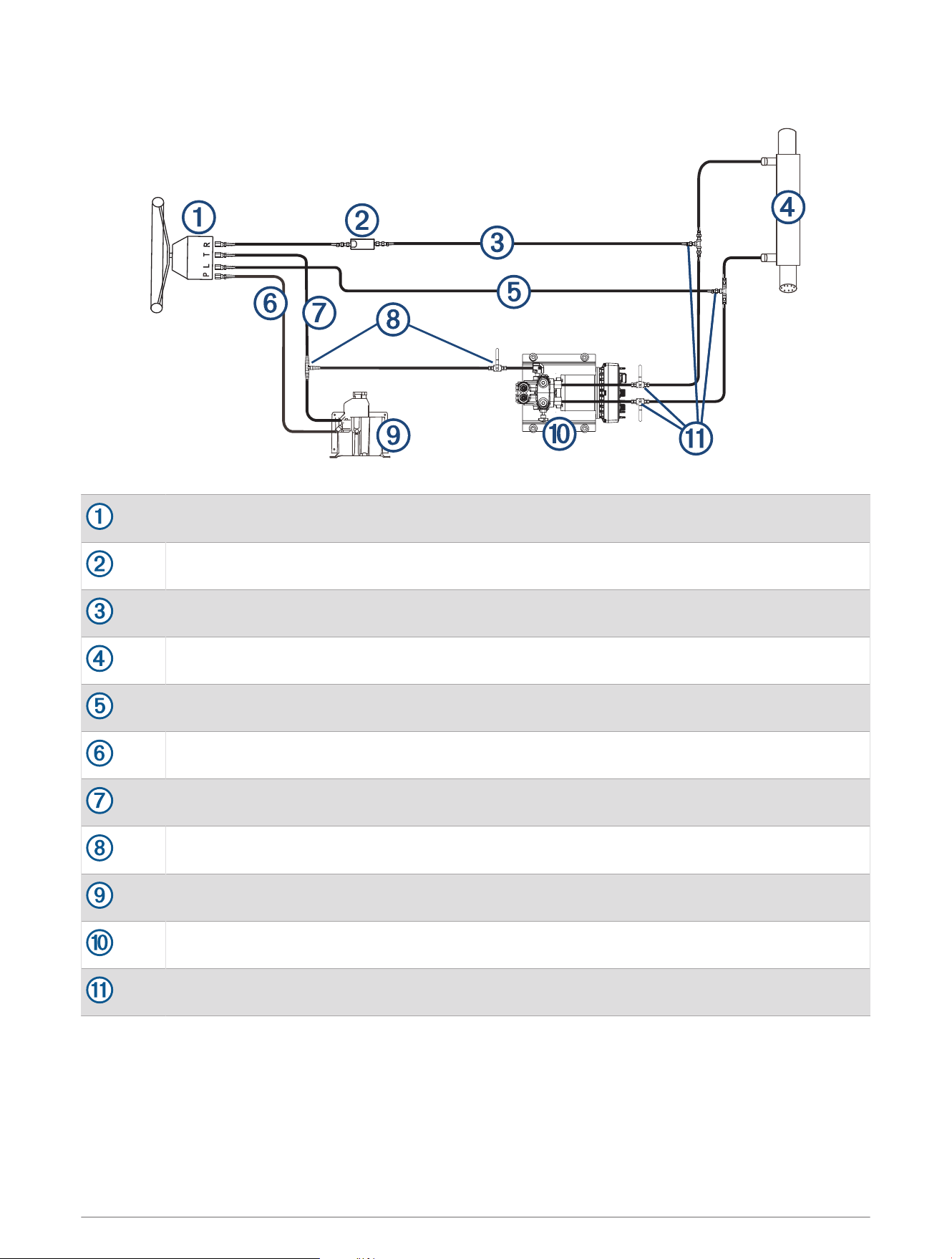
Single-Helm Layout Diagram with Single Cylinder System
Helm
Shadow Drive sensor
Starboard line
Steering cylinder
Port line
High-pressure line (do not remove or cut)
Low-pressure return line
Barbed T-connector and shutoff valve
Mercury pump module
SmartPump
Threaded T-connectors and shutoff valves
5
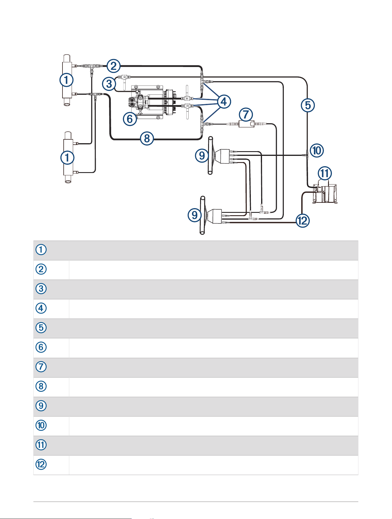
Dual-Helm Layout Diagram
L
T
R
P
L
T
R
P
Steering cylinder
Port line
Barbed shut-off valve
Threaded T-fittings and shut-off valves
Return line
SmartPump
Shadow Drive sensor
Starboard line
Helm
Barbed T-fitting
Mercury pump module
High-pressure line (do not remove or cut)
6
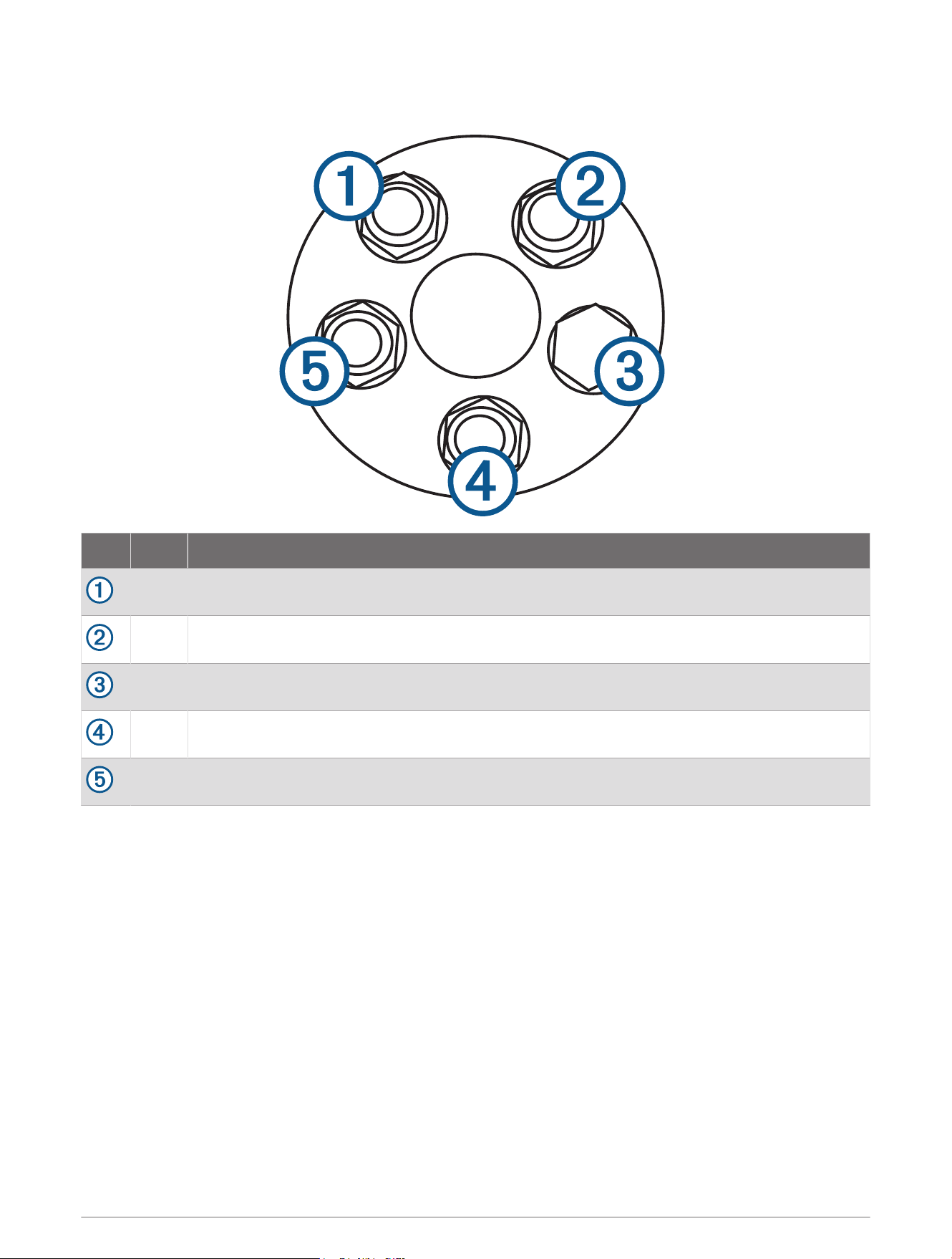
Mercury Verado Helm Connectors
E
R
T
P
L
R
T
P
L
E
Item Label Description
L Hose to the port side of the steering cylinder or cylinders.
R Hose to the starboard side of the steering cylinder or cylinders.
E Plug. Do not remove.
T Hose to the tank of the Mercury pump module.
P High-pressure supply hose from the Mercury pump module. Do not remove or cut.
7
Hydraulic Fittings
This kit includes the hydraulic fittings needed to install the Reactor SmartPump autopilot for use with your
Mercury Verado steering system.
• Two of the ORFS male to NPT male fittings connect the hose to the pump manifold.
• Two of the ORFS male to NPT male fittings and the two NPT male to female fittings connect the hose
to the Shadow Drive sensor .
NOTICE
You must connect both the included NPT and ORFS fittings to the Shadow Drive sensor to prevent flow
restrictions that can result from connecting only ORFS fittings directly to the Shadow Drive sensor.
• The ORFS T-fittings and shut-off ball valves isolate the pump from the hydraulic system as shown in these
instructions.
• You can use the included male-male or male-female ORFS fittings to connect the shut-off ball valves to your
hydraulic system.
NOTE: You should use thread sealant thread sealant, such as Loctite 567, when connecting the fittings to the
pump, the Shadow Drive sensor, and the shut-off ball valves.
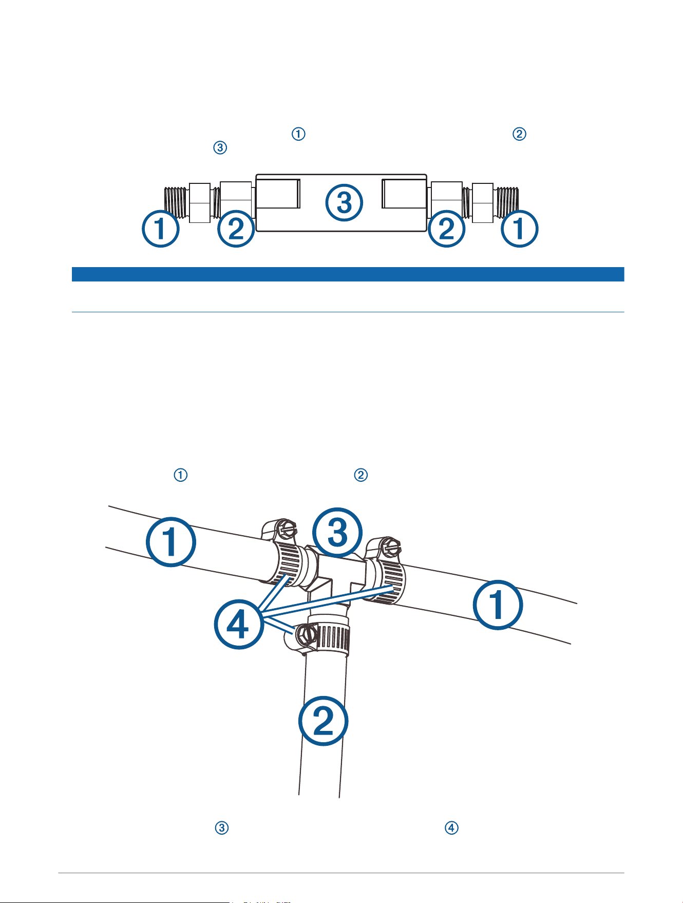
Connecting the Return Hose to the Pump
You must branch the low-pressure, return hydraulic hose from the helm (upper helm only in dual-helm
installations) to the Mercury pump module, and connect it to the autopilot pump.
1 Cut the return hose where you need to add the hose you will route to the SmartPump.
2 Install the included T-fitting in the cut return hose, and securely clamp the connections.
8

3 Install the hose to the SmartPump on the remaining end of the T-fitting, and securely clamp the connection.
4 Screw the threaded end of the included fitting into the SmartPump.
Thread sealant, such as Loctite 567, should be used when connecting the fitting to the pump.
5 Connect the return hose to the barbed end of the fitting you installed on the SmartPump in step 4.
Completing the Installation
1 After the installation is complete, fill the pump reservoir with Mercury steering fluid (not included).
2 Bleed the steering system according to the instructions provided with the steering system.
3 Configure the autopilot according to the configuration guide provided in your autopilot corepack.
© 2018 Garmin Ltd. or its subsidiaries
Garmin
®
and the Garmin logo are trademarks of Garmin Ltd. or its subsidiaries, registered in the USA and other countries. Reactor
™
and Shadow Drive
™
are trademarks of
Garmin Ltd. or its subsidiaries. These trademarks may not be used without the express permission of Garmin.
Mercury
®
and Verado
®
are trademarks of Brunswick Corporation, registered in the USA and other countries. Loctite
®
is a trademark of Henkel Corporation in the U.S. and
elsewhere.
9

© 2018 Garmin Ltd. or its subsidiaries
support.garmin.com