

General Informa,on
2
BlitzFunk User Manual
Release 2026/4
Revision History
Version Change
Release 2025/6
• Ini,al release
Release 2025/7
• Added informa,on on exposed network interfaces
and services
• Added descrip,on of find func,on
• Added informa,on on update no,fica,ons via mail
Release 2025/8
• Added descrip,on of VLAN segmenta,on
• Added descrip,on of the replace func,on
• Added descrip,on for ,me history display of
received signal strength
• Improved descrip,on of status view
• Updated required legal informa,on according to
2014/53/EU
Release 2025/9
• Descrip,on of VLAN segmenta,on revised
• Extended manual for AW32R and CW32R device
types
Release 2025/10
• Descrip,on of firmware update process improved
Release 2026/2
• Added FCC and ISED legal text
Release 2026/3
• Descrip,on of changing the IP address behavior
added

General Informa,on
3
BlitzFunk User Manual
Release 2026/4
Table of Contents
1
General Informa-on .............................................................................................................................. 5
1.1
Product Names ..................................................................................................................................... 5
1.2
Highligh7ng of Tips and Warnings ....................................................................................................... 5
1.3
Legal Informa7on ................................................................................................................................. 5
1.4
Open Source SoCware .......................................................................................................................... 6
1.5
Radio Frequencies and Transmit Power ............................................................................................... 6
1.6
CE ......................................................................................................................................................... 7
1.7
UKCA ..................................................................................................................................................... 7
1.8
WEEE Disposal and Recycling Informa7on ........................................................................................... 8
2
About the Product ............................................................................................................................... 10
2.1
Intended Use ...................................................................................................................................... 10
2.2
Physical Interfaces: Client ................................................................................................................... 11
2.3
Physical Interfaces: Access Point ........................................................................................................ 13
2.4
LED Indicators ..................................................................................................................................... 16
3
Device Installa-on ............................................................................................................................... 18
3.1
Hardware Installa7on ......................................................................................................................... 18
3.2 Antenna Orienta7on and Device Posi7oning ...................................................................................... 18
3.3
Wall or Ceiling Moun7ng .................................................................................................................... 20
3.4
Power and Data Connec7on ............................................................................................................... 20
4 Device Configura-on ............................................................................................................................ 23
4.1
Accessing the Configura7on Interface ................................................................................................ 23
4.2
Password Protec7on ........................................................................................................................... 24
4.3
Assignment of Channel Groups .......................................................................................................... 25
4.4
Extending Coverage with Addi7onal Access Points ............................................................................ 29
4.5
Increasing Capacity with Addi7onal Access Points ............................................................................. 31
4.6
Sepera7on into virtual Networks (VLANs) .......................................................................................... 32
4.7
Changing the Device Configura7on During Opera7on ....................................................................... 37
4.8
Replacing Devices ............................................................................................................................... 43
4.9
Loca7ng Devices ................................................................................................................................. 44
..................................................................................................................................................................... 45

General Informa,on
4
BlitzFunk User Manual
Release 2026/4
5
System Diagnos-cs .............................................................................................................................. 46
5.1
Link Status Monitoring ....................................................................................................................... 46
6
Device Maintenance ............................................................................................................................ 51
6.1
Firmware Updates .............................................................................................................................. 51
6.2 Factory Reset ...................................................................................................................................... 54
7
Technical Data ...................................................................................................................................... 55
8
Troubleshoo-ng and Support ............................................................................................................... 57
8.1
Troubleshoo7ng .................................................................................................................................. 57
8.2
Support ............................................................................................................................................... 58
General Informa,on
5
BlitzFunk User Manual
Release 2026/4
1 General Information
1.1 Product Names
This manual contains informa,on on the products:
• BlitzFunk® Access Point AW32R
• BlitzFunk® Client CW32R
1.2 Highlighting of Tips and Warnings
Throughout the text the following symbols are used:
Tip: This symbol provides helpful guidance or addi,onal details to assist
with product use.
WARNING: This symbol indicates cri,cal safety informa,on. Ignoring
these warnings may result in damage or injury.
1.3 Legal Information
This wireless system is classified as a Category 2 receiver in accordance with ETSI
EN 300 440.
Changes or modifica,ons not expressly approved by the party responsible for
compliance could void the user's authority to operate the equipment.
The devices BlitzFunk AW32R und CW32R comply with ETSI electromagne,c
compa,bility (EMC) standards for industrial environments (Class A devices) and
residen,al environments (Class B devices). Compliance with EMC regula,ons was
verified using shielded Ethernet cables. To ensure con,nued compliance, always
use shielded Ethernet cables when opera,ng this equipment.
This equipment has been tested and found to comply with the limits for a Class A
digital device, pursuant to part 15 of the FCC Rules. These limits are designed to

General Informa,on
6
BlitzFunk User Manual
Release 2026/4
provide reasonable protec,on against harmful interference when the equipment
is operated in a commercial environment. This equipment generates, uses, and can
radiate radio frequency energy and, if not installed and used in accordance with
the instruc,on manual, may cause harmful interference to radio communica,ons.
Opera,on of this equipment in a residen,al area is likely to cause harmful
interference in which case the user will be required to correct the interference at
his own expense.
This equipment complies with EN IEC 62311, FCC and RSS-102 radia,on exposure
limits set forth for an uncontrolled environment. This device and its antenna(s)
must not be co-located or opera,ng in conjunc,on with any other antenna or
transmiaer. This equipment should be installed and operated with a minimum
distance of 20 cm between the radiator & your body.
Cet équipement est conforme aux limites d'exposi7on aux rayonnements IC RSS-102 établies pour
un environnement non contrôlé.
Cet émeceur doit être installé pour fournir une distance de sépara7on d'au moins 20 cm de toutes
les personnes et ne doit pas être colocalisé ou fonc7onner en conjonc7on avec une autre antenne
ou émeceur.
1.4 Open Source Software
Informa,on about open-source licenses used can be viewed in the access point’s
web interface under the Support sec,on.
1.5 Radio Frequencies and Transmit Power
Frequency
Transmit Power
(EIRP, single antenna port)
EU USA / Canada
2.402 GHz – 2.472 GHz
max. 70 mW max. 500 mW
5.17 GHz – 5.25 GHz
max. 80 mW max. 100 mW
5.735 GHz – 5.875 GHz
max. 10 mW max. 200 mW
5.945 GHz – 6.425 GHz
max. 70 mW
max. 60 mW (AW32R)
max. 13 mW (CW32R)
6.425 GHz – 7.125 GHz
-
max. 60 mW (AW32R)
max. 13 mW (CW32R)

General Informa,on
7
BlitzFunk User Manual
Release 2026/4
In AT, BE, BG, CY, CZ, DE, DK, EE, EL, ES, FI, FR, HR, HU, IE, IT, LT, LU, LV, MT, NL, PL,
PT, RO, SE, SI, SK the system may only be used indoors in the frequency ranges 5.15
GHz to 5.35 GHz and 5.945 GHz to 6.425 GHz.
In Canada, the device for opera,on in the band 5150-5250 MHz is only for indoor
use to reduce the poten,al for harmful interference to co-channel mobile satellite
systems. Devices shall not be used for control of or communica,ons with
unmanned aircrak systems. Opera,on shall be limited to indoor use only.
Opera,on on oil plalorms, automobiles, trains, mari,me vessels and aircrak shall
be prohibited except for on large aircrak flying above 3,048 m (10,000 k).
Au Canada, les disposi/fs fonc/onnant dans la bande de 5 150 à 5 250 MHz sont réservés
uniquement à une u/lisa/on à l’intérieur afin de réduire les risques de brouillage préjudiciable aux
systèmes mobiles par satellite u/lisant les mêmes canaux. Les disposi/fs ne doivent pas être u/lisés
pour la commande ou la communica/on avec des systèmes d’aéronefs sans pilote. Le
fonc/onnement est limité à une u/lisa/on à l’intérieur seulement. L’exploita/on sur des
plateformes pétrolières, dans les automobiles, les trains, les navires mari/mes et les aéronefs est
interdite, sauf à bord de gros aéronefs volant à une al/tude supérieure à 3 048 m (10 000 pieds).
In the US, FCC regula,ons restrict the opera,on of this device to indoor use only.
The opera,on of this device is prohibited on oil plalorms, cars, trains, boats, and
aircrak, except that opera,on of this device is permiaed in large aircrak while
flying above 10,000 feet in the 5.925-6.425 GHz band. Opera,on of transmiaers in
the 5.925-7.125 GHz band is prohibited for control of or communica,ons with
unmanned aircrak systems.
1.6 CE
Hereby, fuenfeinhalb Funksysteme GmbH declares that the radio
equipment type BlitzFunk AW32R and CW32R is in compliance
with Direc,ve 2014/53/EU.
The full text ok he EU declara,on of conformity is available at the
following internet address:
h0ps://fuenfeinhalb.de/pdf/CE_Declara<on_of_Conformity.pdf
1.7 UKCA
Hereby, fuenfeinhalb Funksysteme GmbH declares that the radio
equipment type BlitzFunk AW32R and CW32R is in compliance
with the relevant UK statutory requirements.

General Informa,on
8
BlitzFunk User Manual
Release 2026/4
The full text of the UK declara,on of conformity is available at the
following internet address:
h0ps://fuenfeinhalb.de/pdf/UK_Declara<on_of_Conformity.pdf
1.8 FCC
This device complies with part 15 of the FCC Rules. Opera,on is
subject to the following two condi,ons:
(1) This device may not cause harmful interference, and
(2) this device must accept any interference received, including
interference that may cause undesired opera,on.
1.9 ISED
The devices AW32R and CW32R comply with ISED requirements.
This device contains licence-exempt transmiaer(s)/receiver(s) that comply with
Innova,on, Science and Economic Development Canada’s licence-exempt RSS(s).
Opera,on is subject to the following two condi,ons:
(1) This device may not cause interference.
(2) This device must accept any interference, including interference that may
cause undesired opera,on of the device.
L’émePeur/récepteur exempt de licence contenu dans le présent appareil est conforme aux CNR
d’Innova/on, Sciences et Développement économique Canada applicables aux appareils radio
exempts de licence. L’exploita/on est autorisée aux deux condi/ons suivantes:
(1) L’appareil ne doit pas produire de brouillage;
(2) L’appareil doit accepter tout brouillage radioélectrique subi, même si le brouillage est
suscep/ble d’en compromePre le fonc/onnement.
1.10 WEEE Disposal and Recycling Information

General Informa,on
9
BlitzFunk User Manual
Release 2026/4
All products bearing this symbol are waste electrical and electronic
equipment (WEEE as in direc,ve 2012/19/EU) which should not be
mixed with unsorted household waste. Instead, you should protect
human health and the environment by handing over your waste
equipment to a designated collec,on point for the recycling of
waste electrical and electronic equipment, appointed by the
government or local authori,es. Correct disposal and recycling will
help prevent poten,al nega,ve consequences to the environment
and human health. Please contact the installer or local authori,es
for more informa,on about the loca,on as well as terms and
condi,ons of such collec,on points.

About the Product
10
BlitzFunk User Manual
Release 2026/4
2 About the Product
2.1 Intended Use
The BlitzFunk product line is a wireless networking solu,on designed to deliver
highly reliable real-,me wireless connec,vity for industrial environments. It may
serve as a replacement for wired Ethernet in industrial applica,ons and enables
wireless connec,ons for mobile systems.
A BlitzFunk network requires at least one access point and one or more clients.
The system is fully transparent to common industrial Ethernet protocols (e.g.,
PROFINET, PROFIsafe, EtherNet/IP, OPC UA) and func,ons as a Layer 2 switch.
Unlike tradi,onal wireless Ethernet bridges, it is not restricted to point-to-point
links.
BlitzFunk is ideal for small to medium-sized networks with 1 to 20 clients, and can
scale to support up to 100 clients.
Figure 1 Example of a BlitzFunk access point and two BlitzFunk clients in an
industrial Ethernet setup
Access Point
Client
Client
About the Product
11
BlitzFunk User Manual
Release 2026/4
WARNING: While measures have been taken to ensure high reliability
at low latency of the wireless connec,on, wireless links remain subject
to challenging propaga,on condi,ons and poten,al interference. This
may result in data loss. Appropriate fail-safe mechanisms must be
implemented to prevent injury and mi,gate economic risks in the event
of a communica,on failure.
WARNING: This equipment is not suitable for use in loca,ons where
children are likely to be present.
2.2 Physical Interfaces: Client
Figure 2 Front panel of a BlitzFunk client
LED
indicators
Ethernet port
Power port
Antenna ports
(WLAN channel 2)
Antenna ports
(WLAN channel 1)
About the Product
12
BlitzFunk User Manual
Release 2026/4
Clients are powered via the device’s DC port using an external power supply. The
data connec,on is established via the device's ETH port, which supports a 100
Mbit/s Ethernet connec,on.
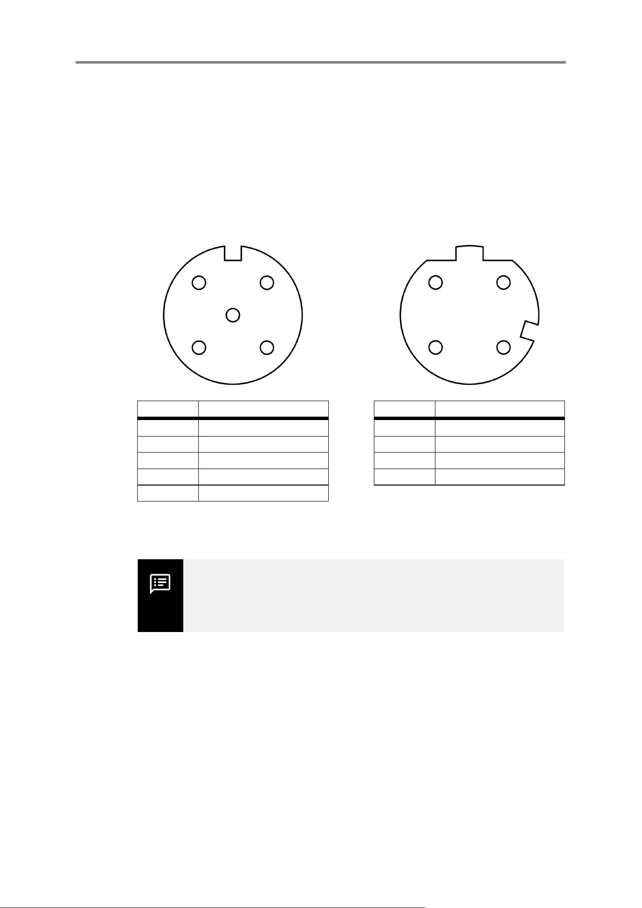
Client DC Port
(M12, 5 pins, A-coded)
Client ETH Port
(M12, 4 pins, D-coded)
Pin Func8on Pin Func8on
1 + 12 to 48 V DC 1 TD+
2 not connected 2 RD+
3 GND 3 TD-
4 not connected 4 RD-
5 not connected
Figure 3 Pin mapping of client connectors (view towards device)
Tip: A reverse polarity protec,on is in place in case the external power
supply is connected to the wrong pins at the DC port.
Clients have four RP-SMA female connectors (Reverse Polarity SubMiniature
Version A) for aaaching antennas. Each port serves different func,ons, such as
exchange of setup messages, data transmission or recep,on, depending on the
opera,ng state of the device:
1
2
3 4
5
1
2
4 3

About the Product
13
BlitzFunk User Manual
Release 2026/4
2.3 Physical Interfaces: Access Point
Interface DirecAon
FuncAon Exposed Service
ANT1 RX / TX WLAN channel 1:
user data & device
setup
Proprietary
protocol
ANT2 RX WLAN channel 1:
user data & device
setup
Proprietary
protocol
ANT3
RX / TX WLAN channel 2:
user data
Proprietary
protocol
ANT4
RX WLAN channel 2:
user data
Proprietary
protocol
ETH
RX / TX User data DHCP client, ARP,
ICMP

About the Product
14
BlitzFunk User Manual
Release 2026/4
Figure 4 Front panel of a BlitzFunk access point
Access points can be powered either via the DC port using an external power
supply or via Power over Ethernet (PoE) according to the IEEE 802.3af standard.
Both PoE mode A and mode B are supported.
The data connec,on is established via the ETH port, which supports a 1000 Mbit/s
Ethernet connec,on.
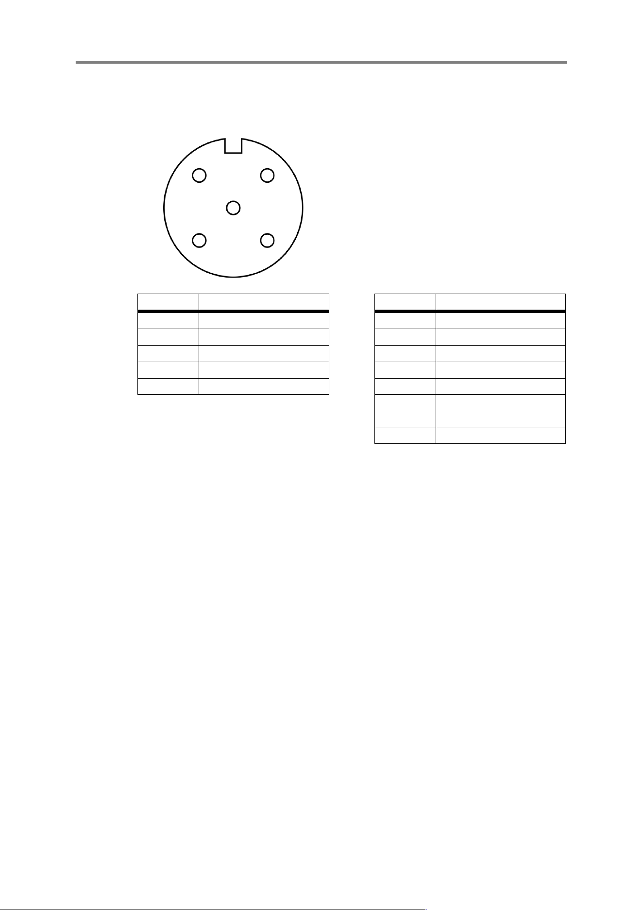
Access Point DC Port
(M12, 5 pins, A-coded)
Access Point ETH|PoE Port
(M12, 8 pins, X-coded)
LED
indicators
Ethernet port with support for
power over Ethernet (PoE)
Power port
Antennas
(WLAN channel 1)
Antenna
(Setup channel)
Antennas
(WLAN channel 2)
About the Product
15
BlitzFunk User Manual
Release 2026/4
Pin Func8on Pin Func8on
1 + 14 to 48 V DC 1 DA-
2 -- 2 DA+
3 GND 3 DC+
4 -- 4 DC-
5 -- 5 DD-
6 DD+
7 DB-
8 DB+
Figure 5 Pin mapping access point connectors (view towards device)
Access points have five non-detachable antennas. In addi,on to the clients, access
points include a dedicated interface for device management, separate from the
interfaces used for data transmission.
1
2
3 4
5
1
2 3
4
5
6 7
8

About the Product
16
BlitzFunk User Manual
Release 2026/4
2.4 LED Indicators
Interface DirecAon
FuncAon Exposed Service
ANT1 RX/TX WLAN channel 1:
user data
Proprietary
protocol
ANT2 RX / TX Device setup Proprietary
protocol
ANT3
RX WLAN channel 1:
user data
Proprietary
protocol
ANT4
RX / TX WLAN channel 2:
user data
Proprietary
protocol
ANT5
RX WLAN channel 2:
user data
Proprietary
protocol
ETH
RX / TX HTTP-configura,on
interface, user
data,
access point
coordina,on
Proprietary
protocol, DHCP
server, DHCP client,
HTTP, ARP
LED Color
Status
PWR
Off No power to device
Yellow Device is wai,ng for configura,on
White
Pulsing: device is star,ng
Permanently on: device is ready for data
Red Error
TX
Off No data is being transmiaed wirelessly
White Data is being transmiaed wirelessly
RX Off No data is being received wirelessly

About the Product
17
BlitzFunk User Manual
Release 2026/4
White Data is being received wirelessly
PWR/TX/RX
Blue Anima,on for finding a device
Turquoise Indica,on for a factory reset
Device Installa,on
18
BlitzFunk User Manual
Release 2026/4
3 Device Installation
3.1 Hardware Installation
Before using client devices, connect all included antennas to their designated
antenna ports. Only use antennas that come with the device. Antennas should be
fastened by hand ,ght or ,ghtened with a maximum torque of 0.9 Nm. Access
point devices come with antennas already aaached.
WARNING: Powering the device without connec,ng all antennas to the
RP-SMA ports may cause damage. Using only some antennas can result
in the device not func,oning as intended.
,
WARNING: Only antennas provided with this device shall be used. The
use of any unauthorized or non-approved antennas may result in non-
compliance with regulatory requirements and could cause harmful
interference. Unauthorized modifica,ons or subs,tu,ons may void the
user’s authority to operate this equipment.
Tip: For installa,ons in ,ght spaces, such as interior-mounted
equipment, clients can operate with reduced reliability by rou,ng only
the RX/TX ports to the exterior (e.g. ANT1 and ANT3). The other
antennas are receive-only, they do not need to be RF-terminated if
unused.
3.2 Antenna Orientation and Device Positioning
The angle of the antennas can impact both coverage and connec,on stability. For
maximum range with line-of-sight, the antennas of access point and client must be
aligned parallel to each other.

Device Installa,on
19
BlitzFunk User Manual
Release 2026/4
Figure 6 Recommended antenna posi,oning
Avoid placing antennas inside or behind metallic enclosures, such as control
cabinets or within automated guided vehicles, as this will degrade signal quality
significantly. If the device must be installed inside a metal enclosure, use RP-SMA
extension cables to route the antennas to the outside.
Figure 7 Antenna moun,ng outside of metallic enclosures
The achievable range of the system depends on environmental condi,ons. Op,mal
range is typically achieved when there is a clear line of sight between the access
point and the client.
Device Installa,on
20
BlitzFunk User Manual
Release 2026/4
WARNING: This device and its antenna(s) must not be co-located or
opera,ng in conjunc,on with any other antenna or transmiaer.
This equipment should be installed and operated with a minimum
distance of 20cm between the radiator & your body.
3.3 Wall or Ceiling Mounting
At the desired loca,on, the device should be securely mounted to a wall or ceiling
using its integrated moun,ng holes.
WARNING: To prevent injury from falling equipment, the device should
be secured by an expert. Depending on the material ok he wall or
ceiling, suitable wall anchors have to be selected. It always needs to be
verified that the moun,ng surface is stable and capable of bearing the
weight of the device.
3.4 Power and Data Connection
Connect both the client and access points to power. They must be supplied with
an external DC power source via the DC port. An access point device can
alterna,vely be powered through its ETH/PoE port using Power over Ethernet
(PoE).
WARNING: To ensure the safety of the product, the devices shall
always be supplied with ES1 and LPS | PS2 | Class 2 power sources.
Pour garan/r la sécurité du produit, les appareils doivent toujours être alimentés par
des sources d’alimenta/on ES1 et LPS | PS2 | Classe 2.
Device Installa,on
21
BlitzFunk User Manual
Release 2026/4
Figure 8 Op,ons for powering clients and access point
Tip: If both DC and PoE are connected, the device will draw power from
the DC supply. In this configura,on, PoE will act as a backup in case the
DC supply fails.
Connect the data ports of the devices to the end devices which shall establish
connec,on. In systems with mul,ple access points, the ETH ports of all access
points must be interconnected, for example via a network switch. To ensure proper
synchroniza,on between access points, the network infrastructure must support
1 Gbit/s Ethernet speeds and maintain a maximum latency of 50 microseconds.
Typical Gigabit Ethernet switches forward packets in less than 15 microseconds,
PoE injector
(802.3 af)
Injector
power
supply
Power
supply
(14 – 48 V DC,
4.8 W average,
15 W peak)
Power
supply
(12 – 48 V DC,
4.1 W average,
10 W peak)
22
BlitzFunk User Manual
Release 2026/4
allowing up to three switches in series. The VLAN ID 512 is used for communica,on
between the access points. When a managed Ethernet switch is used to connect
the access points, it must be ensured that traffic with this VLAN ID is forwarded to
all connected access points.
Figure 8 Access point connec,on in a setup consis,ng of mul,ple access points
WARNING: To maintain protec,on against dust and water ingress, both
M12 ports must be connected. It is recommended to ,ghten the
connectors to a torque of 0.6 Nm. To ,ghten the ports using a torque
wrench, the antennas must be removed to allow access. If a port is not
in use, it must be sealed with a suitable protec,ve cap to preserve the
device’s protec,on ra,ng.
Ethernet switch
(1 Gbit/s,
<50 microsecond latency)
Device Configura,on
23
BlitzFunk User Manual
Release 2026/4
4 Device Configuration
Before data transmission can take place, when powering the devices for the first
,me or when replacing exis,ng ones, the system must be configured.
Configura,on is performed using the web-based interface of the access point,
which can be accessed from any standard, up-to-date web browser. The following
sec,ons explain the available func,ons of the configura,on interface using
example setups.
Tip: Issues that may occur when using the system for the first ,me are
summarized in chapter 8 (ref. Troubleshoo<ng).
4.1 Accessing the Configuration Interface
To access the configura,on interface, a computer is required with:
• a web-browser
• one free Ethernet port
Connect the computer via Ethernet to the access points that are awai,ng
configura,on. Power must be supplied to the access points.
Clients that require configura,on must be powered on and within wireless range
of at least one access point. Clients must not be connected to the access points by
cable, as this will create a network loop once the system is configured.
By default, the configura,on interface is accessible at:
Tip: The system can be configured while already installed in its final
loca,on. Although a temporary connec,on to a computer is needed for
configura,on, the cabling used during configura,on is the same as in
the system's opera,onal state.
h"p://10.5.0.1

Device Configura,on
24
BlitzFunk User Manual
Release 2026/4
In networks with more than one BlitzFunk access point, the access point with the
lowest serial number is automa,cally designated as the coordina,ng access point
(coordinator). The web interface is provided by the coordina,ng access point.
In the factory default configura,on, the coordina,ng Access Point operates with
an integrated DHCP server enabled, assigning IP addresses in the range 10.5.0.12
to 10.5.0.254. The IP address and DHCP server sesngs of the coordina,ng Access
Point can be configured through the configura,on interface (ref. Changing the IP
Adress Behaviour).
Ensure that the computer used for configura,on has an IP address in the same
subnet as the coordina,ng access point.
4.2 Password Protection
By default, the configura,on interface is accessible from any device within the
same network. To restrict access, you can set a password in the Password tab of
the configura,on interface. This ensures that only authorized users can modify
system sesngs.
Device Configura,on
25
BlitzFunk User Manual
Release 2026/4
To set a password, click the Enable toggle, enter the desired password, and click
Apply. You can choose whether read access (viewing without making changes) is
allowed without a password or not.
Tip: Please note that the HTTP connec,on to the web interface is not
secured. For security reasons, ensure that the chosen password is not
used anywhere else.
Aker applying, you are automa,cally logged in. You may log out via the Log Out
Buaon.
4.3 Assignment of Channel Groups
Before data can be transmiaed between devices, they need to be assigned to a
channel group. To do this use the Channels & Devices tab.
1
2
3
Device Configura,on
26
BlitzFunk User Manual
Release 2026/4
BlitzFunk devices communicate within channel groups. A channel group uses two
redundant 20 MHz channels for data transmission. To create a channel group, first
select two opera,ng channels by clicking Create Channel Group.
To increase the reliability of the system, it is recommended to separate the two
channels with more than 100 MHz separa,on. Adjacent channels cannot be
selected.
For device management, BlitzFunk uses channel 149 at 5745 MHz. This channel is
currently fixed but will be made configurable in a future.
Tip: The achievable range depends on the legally permiaed
transmission power. At 2.4 and 5.2 GHz, greater ranges can be expected
than at 5.8 and 6 GHz. Channels in the laaer frequency ranges are
therefore referred to as Short Range.
Tip: The frequency bands with shorter range at 5.8 GHz (5765 – 5865
MHz) and 6 GHz (5955 – 6415 MHz), are generally less crowded than
other frequency bands and therefore more reliable than the lower
frequencies.
Device Configura,on
27
BlitzFunk User Manual
Release 2026/4
Add devices to a channel group by dragging and dropping them into it, or by
selec,ng the desired devices using the Add Device buaon. Available devices are
shown at the boaom in the Available Devices sec,on. Access points are always
available when connected via Ethernet. Clients are available when they are not
assigned to any channel group (indicated by the yellow PWR LED), or when they
cannot find an access point belonging to their channel group.
The number of clients in a channel group affects both latency and data throughput.
The first client is connected with a data rate of 6 Mbit/s and a maximum one-way
latency of 4 ms. Each addi,onal client increases latency by 2 ms. The data rate is
evenly distributed among all clients in a channel group. Some example values are
provided in the table below.
Clients per Channel
Group
Max. One-Way Latency [ms] Data Rate [Mbit/s]
1 4 6
2 6 3
4 10 1.5
10 22 0.6
24 50 0.25
48 100 0.125

Device Configura,on
28
BlitzFunk User Manual
Release 2026/4
The expected maximum one-way latency and data rate are displayed for each
client during configura,on.
When changes to the configura,on are pending, two buaons appear at the boaom
center of the screen. To apply the configura,on, click Apply Changes. As soon as
at least one access point and one client have been assigned to a channel group,
data transmission between the devices can begin, and the PWR LEDs of the devices
will turn white.
Device Configura,on
29
BlitzFunk User Manual
Release 2026/4
Alterna,vely, pending changes can be reverted using the Discard op,on. The
configura,on interface will then be reloaded.
WARNING: Changing the configura,on of devices that are already
configured may cause an interrup,on in data transmission. To avoid
unplanned down,me of your machines, please observe the
instruc,ons in the sec,on Changing the Device Configura<on during
Opera<on.
4.4 Extending Coverage with Additional Access Points
To extend the coverage of a BlitzFunk network, addi,onal access points can be
assigned to a channel group. No addi,onal channels are required for this since the
access points coordinate with each other and use the same two channels.
Clients can move freely between access points within the same channel group
without interrup,ons and without affec,ng latency or data rate (latency-free
roaming).
For a stable connec,on, it must simply be ensured that the signal strength is
sufficient at every possible client posi,on (ref. Link Status Monitoring). To achieve
this, an unobstructed line of sight to at least one of the access points should always
be maintained. When using channels in the 6 GHz band, the distance to the nearest
access point should be less than 40 meters.

Device Configura,on
30
BlitzFunk User Manual
Release 2026/4
To use this func,onality, access points need to be connected via Gigabit-Ethernet
(ref. Power and Data Connec<on) and placed with overlapping coverage. The
connec,ng switch should ideally not have to process any other data traffic and
should not exceed a latency of 50 microseconds for frame sizes up to 1522 bytes.
Figure 9 Example for a setup containing mul,ple access points to increase
coverage
In the configura,on interface, add mul,ple access points to a channel group. Add
clients to the channel group and press Apply Changes to confirm.
Network
switch

Device Configura,on
31
BlitzFunk User Manual
Release 2026/4
4.5 Increasing Capacity with Additional Access Points
To increase the data rate per client and reduce latency, mul,ple channel groups
can be operated in parallel. Latency and data rate scale independently for each
channel group. Unless separated from each other by virtual networks (ref.
Segmenta<on into Virtual Networks (VLANs)), a client can exchange data with all
other clients, regardless of which channel group they belong to.
For a setup with mul,ple channel groups, a separate access point is required for
each group. The access points must be connected to each other via Gigabit-
Ethernet (ref. Power and Data Connec<on).
Figure 10 Example for a network with mul,ple access points to increase capacity
and reduce latency
In the configura,on interface, create mul,ple channel groups and assign one
access point to each group. Add clients to the corresponding channel group and
press Apply Changes to confirm the configura,on.
Network
switch

Device Configura,on
32
BlitzFunk User Manual
Release 2026/4
4.6 Seperation into virtual Networks (VLANs)
Clients in a BlitzFunk network can be isolated from one another using virtual
networks (VLANs). This allows independent applica,ons to operate on the same
infrastructure without mutual interference. It also helps limit the impact of
cybersecurity incidents and reduces the scope of broadcast frames, thereby
providing more capacity for each applica,on.
VLAN-specific sesngs are configured in the Virtual Networks tab.
BlitzFunk implements VLANs according to the IEEE 802.1Q standard. Data is
assigned to a VLAN by means of an addi,onal field (the so-called VLAN ID) in the
Device Configura,on
33
BlitzFunk User Manual
Release 2026/4
header of the Ethernet frame. A VLAN is iden,fied by a number between 1 and
4095.
For each client, the following VLAN op,ons can be assigned:
Mode FuncAon
Standard Devices connected to the client receive only data without
a VLAN ID or data with a VLAN ID 0 (e.g. PROFINET). Data
entering the client via Ethernet is accepted only if it has
no VLAN ID or a VLAN ID 0 and is then forwarded to the
access point. For traffic with VLAN ID 0, the complete
802.1Q header is transmiaed unchanged.
Virtual Network
Devices connected to the client receive only data with
the matching VLAN ID. The complete 802.1Q-Header
including its VLAN ID is removed by the client when
outpusng data via Ethernet, so the connected devices
do not need to process VLAN IDs. Data entering the
client via Ethernet without a VLAN ID is assigned the
appropriate ID and forwarded to the access point. Data
entering the client via Ethernet with an 802.1Q-Header,
the VLAN ID is replaced with the configured value.
Trunk
All data is forwarded regardless of its VLAN ID. The
complete 802.1Q header is transmiaed unchanged. This
allows VLAN-capable switches to be operated on this
client.

Device Configura,on
34
BlitzFunk User Manual
Release 2026/4
Access points are always in trunk mode. If clients have been assigned to a virtual
network and this virtual network needs to be accessed on the access-point side, a
VLAN-capable switch must be used.
Tip: The DHCP server and HTTP server of the access point are not part
of any VLAN. This means that only clients in standard mode or trunk
mode, as well as devices connected to these clients, can obtain an IP
address from the built-in DHCP server. Likewise, the configura,on
interface is only accessible through clients in standard or trunk mode.
In the following example, a virtual network is set up for each client in order to
create logically separated point-to-point connec,ons at the Ethernet level
between controllers at the access point and a remote I/O module at each client.
Figure 11 Example of two logically separated point-to-point connec,ons
over a shared physical BlitzFunk network
Managed
Switch
VLAN 1000 VLAN 1001
VLAN 1001 VLAN 1000
Trunk

Device Configura,on
35
BlitzFunk User Manual
Release 2026/4
In the configura,on interface of the access point, create two VLANs by clicking the
Add VLAN buaon twice.
The used VLAN ID can be modified via the entry in the table header.

Device Configura,on
36
BlitzFunk User Manual
Release 2026/4
Addi,onally, the name of the VLAN can be modified in the table header.
Add a client to the first virtual network by clicking the Add Clients buaon or by
dragging the client into the virtual network. Repeat the process for the second
client and the second virtual network.
Aker clicking the Apply Changes buaon, the traffic between the two clients is
isolated. For traffic from devices connected to access points to reach the respec,ve
client, it must contain the corresponding VLAN ID (in this example VLAN ID 1000
or 1001).
Device Configura,on
37
BlitzFunk User Manual
Release 2026/4
To allow the controllers to reach the clients in their VLAN, the managed switch
between the access point and the controllers must be configured as follows:
• The port connected to the access point must be configured to
transparently forward any VLANs (trunk mode).
• The ports connected to the controllers must each be assigned to one of
the previously created VLANs (in this example 1000 or 1001) and
configured to apply the corresponding ID to incoming traffic and remove
the ID from outgoing traffic (untagged mode).
4.7 Changing the IP Address Behavior
Access to the configura,on interface requires the coordina,ng Access Point to
have an IP address. In addi,on, IP addresses can be assigned to individual clients,
for example for diagnos,c and monitoring purposes.
Tip: Assigning IP addresses to clients is only intended to make the
devices themselves reachable, for example for diagnos,c purposes.
User data transmission through the BlitzFunk network operates
transparently on Layer 2 and does not require IP address configura,on
on client devices.
The sesngs for the IP address behavior are located in the IP Addresses tab of the
configura,on interface.

Device Configura,on
38
BlitzFunk User Manual
Release 2026/4
The following op,ons are available for the different device types:
Device Type Op8on Func8on
coordina,ng access point
(lowest device ID among
access points)
DHCP Server
(default sesng)
The coordina,ng Access Point
operates as a DHCP server
and assigns IP addresses to
connected network devices
within the configured address
range.
Sta,c IP A fixed IP address and subnet
mask are assigned to the
coordina,ng Access Point.
DHCP Client The coordina,ng Access Point
automa,cally requests an IP
address from a DHCP server in
the network.
client
No IP (default
sesng)
No IP address is assigned to
the client.
Sta,c IP A fixed IP address and subnet
mask are assigned to the
client.

Device Configura,on
39
BlitzFunk User Manual
Release 2026/4
DHCP Client
The client automa,cally
requests an IP address from a
DHCP server in the network.
The different op,ons for the coordina,ng Access Point can be selected from the
Access Mode drop-down menu in the Coordinator Access sec,on.
Changing the Coordina8ng Access Point Behavior
In the default sesng DHCP Server, the addi,onal sec,ons DHCP Server and
DHCP Leases are displayed. In the DHCP Server sec,on, the address range used
by the integrated DHCP server can be configured. Assigned IP addresses have a
limited validity period, which is defined by the Lease Dura,on sesng. The address
range is defined using the Range Start and Range End sesngs.

Device Configura,on
40
BlitzFunk User Manual
Release 2026/4
All IP addresses currently assigned by the integrated DHCP server are displayed
in the DHCP Leases sec,on. The IP address and subnet mask of the DHCP server
itself are configured using the IP Address field.
When changing the coordinator access mode to Static IP or DHCP Client and
confirming the change using the Apply Changes buaon, the integrated DHCP
server is disabled. The configura,on interface is then reachable either via the
configured IP address (op,on Static IP) or via the IP address assigned by the
external DHCP server (op,on DHCP Client).

Device Configura,on
41
BlitzFunk User Manual
Release 2026/4
Changing the Bevharor of Clients
All clients currently within wireless range are displayed in the Devices section.
The desired IP address behavior for each client can be selected in the Behavior
column of the corresponding device entry.
In the default sesng No IP, a client does not have an IP address assigned. For
diagnos,c purposes, the op,ons Static IP, which assigns a fixed IP address to the
client, or DHCP Client, where the client obtains an address using the DHCP
protocol, can alterna,vely be used. The IP address of a client can, for example, be
used to verify network connec,vity to the device using ping.
If a client has obtained an IP address using the DHCP Client op,on, a new IP
address can be requested before the current lease dura,on expires by pressing the
buaon next to the displayed IP address.
Device Configura,on
42
BlitzFunk User Manual
Release 2026/4
Hinweis: When a device (coordinator or client) is operated as a DHCP
client, IP addresses are assigned automa,cally via the network. This
generates addi,onal network communica,on, which may affect real-
,me communica,on performance depending on overall network load.
For applica,ons with par,cularly high real-,me requirements, the use
of sta,c IP addresses or opera,on without an IP address is therefore
recommended to ensure the most consistent and determinis,c
communica,on possible.
4.8 Changing the Device Configuration During Operation
BlitzFunk supports configura,on changes at run,me. Applying such changes
results in only minimal interrup,ons, depending on the type of change. The
dura,on of the interrup,on affects all devices within the configura,on:
Device Type Ac8on Dura8on of the Interrup8on
client
adding device
< 2 ms
removing device
coordina,ng access point
(lowest device ID among
access points)
adding device
< 5 s
removing device
< 1 s
non-coordina,ng access
point
adding device
< 50 ms
removing device
If an access point fails and becomes unavailable, the same interrup,on dura,on as
when removing that access point applies. Aker this ,me, another access point in
the configura,on can take over, provided the client is within its range.

Device Configura,on
43
BlitzFunk User Manual
Release 2026/4
4.9 Replacing Devices
If a configured device is no longer ac,ve, it can be replaced with a new one in just
a few steps. Devices that are no longer connected to the system display a Replace
buaon, which allows you to select a replacement device.
Select a new device, which replaced the device that is not connected anymore.

Device Configura,on
44
BlitzFunk User Manual
Release 2026/4
Confirm the replaced device by clicking Apply Changes. Changing the
configura,on causes a brief interrup,on of all connected devices, depending on
the type of device being replaced (ref. Changing the Device Configura<on during
Opera<on).
4.10 Locating Devices
If devices are already installed, the device ID on the back may no longer be visible,
which can make it difficult to match the entries in the configura,on interface to
the corresponding physical devices. In this case, press the Find buaon next to the

45
BlitzFunk User Manual
Release 2026/4
device entry in the interface. The device’s LEDs will flash blue to indicate its
loca,on.
To stop the locate anima,on on the device press the buaon again.

System Diagnos,cs
46
BlitzFunk User Manual
Release 2026/4
5 System Diagnostics
5.1 Link Status Monitoring
For configured clients, detailed status informa,on about the wireless connec,on
can be viewed in the configura,on interface (ref. Accessing the Configura<on
Interface). Click the client’s Details buaon to open it.
The menu gives detailed status informa,on about:
Reported Metric
Meaning
ID Serial number of the client
Name User-defined device name
MAC Address MAC address of the Ethernet interface
IP Address
Displays the IP address and subnet of the
client. The displayed IP address can, for
example, be used to check the network
connec,on to the client (e.g., using a ping).
Started
Dura,on since the client was started.

System Diagnos,cs
47
BlitzFunk User Manual
Release 2026/4
Last Seen
Dura,on since the client last connected to an
access point.
Connected To
Displays the access point the client is currently
connected to.
Receive Power per Channel
Displays the wireless signal strength of each
wireless link used during opera,on between
the client and the currently connected access
point. A low receive power indicates coverage
issues due to a large distance from the access
point, an improperly mounted antenna, or a
setup in which the antenna is obstructed by
metal.
Transmiaed Frames
(Transmit Direc,on /
Receive Direc,on)
Displays the number of Ethernet payloads that
the devices received for transmission.
Dropped Frames
(Transmit Direc,on /
Receive Direc,on)
Displays the number of packets that have been
dropped. When the system is overloaded with
more data than can be transmiaed, packets
are dropped to ensure real-,me performance
for newer packets. A value greater than zero
indicates that more data is being generated
than the wireless system can handle.
Overloading is expected for short periods
when using the transport control protocol
(TCP).
Losts Slots
(Transmit Direc,on /
Receive Direc,on)
Displays the number of packets lost over the
wireless link. A value greater than zero
indicates coverage issues or strong
interference from other wireless networks on
the opera,ng channels.
Custom Antennas
Allows adjustment of the antenna gain when
antennas other than the default ones are used.

System Diagnos,cs
48
BlitzFunk User Manual
Release 2026/4
In addi,on to the displayed metrics, the Time Series buaon allows the recep,on
power per channel to be displayed over ,me. The ,me series is only recorded
while the browser window remains open. Reloading the browser window resets
the displayed ,me series.
Firmware
• Version: Firmware version number. This field
is not displayed for development versions.
• Commit: Unique iden,fier of the device
firmware.
• Date: Crea,on date of the firmware.
System
• Version: Opera,ng system version number.
This field is not displayed for development
versions.
• Commit: Manufacturer iden,fica,on of the
opera,ng system.
• Fingerprint: Unique iden,fier of the device’s
opera,ng system.
• Date: Crea,on date of the opera,ng system.

System Diagnos,cs
49
BlitzFunk User Manual
Release 2026/4
To obtain detailed informa,on for a specific point in ,me, move the mouse to the
desired posi,on in the chart.
To mark specific points in the chart (e.g., to indicate the client’s loca,on at that
,me), a label can be added for a selected point in ,me using the Label buaon.

System Diagnos,cs
50
BlitzFunk User Manual
Release 2026/4
When troubleshoo,ng an installa,on, the counters in the table entry sta,s,cs can
be reset by clicking the table head with a doaed underline.
Device Maintenance
51
BlitzFunk User Manual
Release 2026/4
6 Device Maintenance
6.1 Firmware Updates
Devices can be updated via the configura,on interface (ref. Accessing the
Configura<on Interface). Upda,ng devices while they are configured may fail and
should preferably be performed in the unconfigured state (devices with a yellow
PWR LED).
WARNING: When performing an update or a firmware synchroniza,on
on a configured system, data transmission will be interrupted. Due to
the addi,onal load on the system, interrup,ons may also occur even if
only devices outside the configura,on are being updated. All devices
must be reconfigured aker the update.
To update the devices, switch to the firmware tab in the configura,on interface.
To upload a new firmware, select a firmware file from your computer using the
Upload Firmware buaon or drag a firmware file into the window.

Device Maintenance
52
BlitzFunk User Manual
Release 2026/4
By default, all devices in the list are preselected to receive the uploaded firmware.
By clicking the corresponding checkbox, the device can be removed from receiving
the update.
By clicking the Update Devices buaon, the firmware will be distributed to all devices
showing a ac,vated checkbox in the list.

Device Maintenance
53
BlitzFunk User Manual
Release 2026/4
If there is a firmware mismatch between devices, they can be synchronized to the
same firmware using the Synchronize Firmwares buaon. The buaon is only displayed
in case of a firmware mismatch. All devices are updated to the firmware version of
the coordina,ng access point. If devices are to be updated to a different firmware
version than that of the coordina,ng access point, the corresponding firmware
version must be uploaded using the Upload Firmware op,on.
Aker a firmware update or a firmware synchroniza,on, the configura,on is
deleted, and the devices restart into setup mode. Then, the devices need to be
reconfigured (ref. Device Configura<on).

Device Maintenance
54
BlitzFunk User Manual
Release 2026/4
Tip: Send an email to contact@fuenfeinhalb.de with subject line
„Update No,fica,on“ to be be informed about new firmware updates.
6.2 Factory Reset
To perform a factory reset, power off and on the device exactly three ,mes within
the first two seconds of startup. When all three LEDs light up blue, allow the device
to con,nue boo,ng. During startup, the device will delete its configura,on and
briefly flash all LEDs yellow to indicate the reset. It will then restart in setup mode.
Figure 12 Visualiza,on of how the device displays the number of power cycles
performed at the beginning of its startup phase. This also applies to access points.
1 power cycle 2 power cycles 3 or more power cycles

Technical Data
55
BlitzFunk User Manual
Release 2026/4
7 Technical Data
Mechanical Data
Width
Client 100 mm
AP 160 mm
Height (without antennas)
Client 130 mm
AP 140 mm
Depth
Client
36 mm
AP
39 mm
Moun,ng
Wall moun,ng
Environmental CondiAons
Opera,ng temperature -20 °C to 60 °C
Degree of protec,on IP65 (CW32R), IP6X (AW32R)
ConnecAons
Power Supply
Client
12 – 48 V DC;
4.1 W average; 10 W peak
AP
14 – 48 V DC or
PoE 802.3af mode A / mode B;
4.8 W average; 15 W peak
DC M12, 5-pin, A-coded
Ethernet
Client M12, 4-pin, D-coded; 100 Mbit/s
AP M12, 8-pin, X-coded; 1000 Mbit/s
Antennas
RP-SMA female, 50 Ω (CW32R), Integral
(AW32R)
Quality of Service
Maximum one-way latency
4 ms for 1 Client
+2 ms per addi,onal client
Addi,onal roaming latency
0 ms
Data rate 6 Mbit/s shared between clients
Payload per Ethernet frame 1500 Bytes
Reliability
99.999999 % for specified latency and
data rate

Technical Data
56
BlitzFunk User Manual
Release 2026/4
Wireless Features
Center
frequencies
2412 MHz – 2462 MHz
5180 MHz – 5240 MHz
5745 MHz – 5865 MHz
5955 MHz – 6415 MHz
6435 MHz – 7115 MHz (USA / Canada)
Bandwidth
2 × 20 MHz

Troubleshoo,ng and Support
57
BlitzFunk User Manual
Release 2026/4
8 Troubleshooting and Support
8.1 Troubleshooting
Problem: Web interface not accessible
It takes about 30 seconds aker powering on an access point before the web
interface becomes available. When devices are in setup mode, which is indcated
by a yellow PWR LED, the interface can only be accessed through access points,
not from client devices. Make sure the URL in your browser is h0p://10.5.0.1 and
not h0ps://10.5.0.1. If another DHCP server is ac,ve on the network, locate the
access point's IP address in the DHCP lease list.
Problem: New client does not appear or disappears occasionally (grey status
indica<on or device is completely missing in the web interface)
This is likely caused by low signal strength. Verify that all antennas are properly
mounted on both access points and clients. Antennas should be ,ghtened hand
,ght or using a torque of 0.9 Nm. Try moving the client closer to the nearest access
point or install another access point nearby. Avoid shielding antennas with metallic
objects like control cabinets or machine housings. For devices mounted in metal
enclosures, use low-loss RP-SMA cables rated up to 7 GHz to posi,on the antennas
outside.
Problem: Addi,onal access point does not appear in the web interface
For coordina,on between the access points, VLAN ID 512 is used. If you are using
managed Ethernet switches to connect the access points, ensure that VLAN ID 512
is forwarded by the switch.
Problem: Occasional communica<on errors and outages
This may be due to system overload, weak signal strength, or interference from
other wireless networks opera,ng on the same channels. In the web interface,
open the client’s status and check the reported values (ref. Link Status Monitoring).
If buffer overflows are rising, the system is overloaded and must be supplied with
less data. If the receive power drops below -80 dBm and packet loss increases,
refer to the signal strength ,ps above. If receive power is good (above -60 dBm)
but packet loss is s,ll high, interference is likely. Try using different channels with
at least 80 MHz spacing.
Problem: Unexpected con<nuous ac<vity on TX and RX-LEDs in combina<on with
communica<on errors and difficul<es accessing the web interface

Troubleshoo,ng and Support
58
BlitzFunk User Manual
Release 2026/4
The system is likely overloaded. If you do not expect high traffic from the
applica,on, check your network for loops. Ensure that none of the clients are
connected to the access points using a wired connec,on.
Problem: Otherwise inexplicable behavior
Unexpected behavior can occur during undervoltage condi,ons. If the device is
powered through the DC connector, ensure that the supply voltage does not drop
below 10 volts. When using Power over Ethernet (PoE), make sure the PoE source
(e.g. a PoE switch) is compliant with at least IEEE 802.3af and is capable of
supplying sufficient power. Note that not all switches can power every port
simultaneously at full load.
Do not power off the device during firmware updates or configura,on changes. In
rare cases, unexpected behavior may also result from sokware bugs. You can
always recover from invalid configura,ons by performing a factory reset (ref.
Factory Reset).
8.2 Support
For technical assistance, troubleshoo,ng, or product inquiries, please contact our
support team at cont[email protected] or call +49 351 8966 5590.
fünfeinhalb Funksysteme GmbH
Chemnitzer Straße 78A
01187 Dresden, Germany