
- 2 -
Overview
The TAP-M310R-SFP Series wireless APs are ruggedized IEEE 802.11ax
wireless solutions for railway train-to-ground (T2G) applications,
including CBTC and CCTV communications. Featuring an IP67 dust-
tight, waterproof design, the TAP-M310R-SFP Series ensures reliable
operations in heavy-duty outdoor environments.
The TAP-M310R-SFP Series is designed for wayside applications and
features an AC power module and an SFP fiber port for easy
deployment.
The TAP-M310R-SFP Series complies with industrial standards and
railway approvals, covering operational temperature ranges, power
input voltage, surge protection, ESD, and vibration resistance.
NOTE
The IP67-rated design provides protection against dust and
water. However, if installed in certain specific outdoor
environments such as coastal areas with high salinity, or highly
polluted regions, it is recommended to use an additional
enclosure to further protect the device’s exterior housing.
Package Checklist
The TAP-M310R-SFP Series is shipped with the following items. If any of
these items are missing or damaged, please contact your customer
service representative for assistance.
• 1 TAP-M310R-SFP Series wireless AP
• Quick installation guide (printed)
• Warranty card
- 3 -
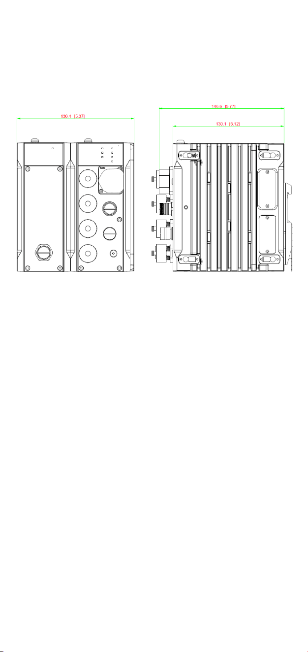
Dimensions
TAP-M310R-1PSFP Models
Unit: mm
- 4 -
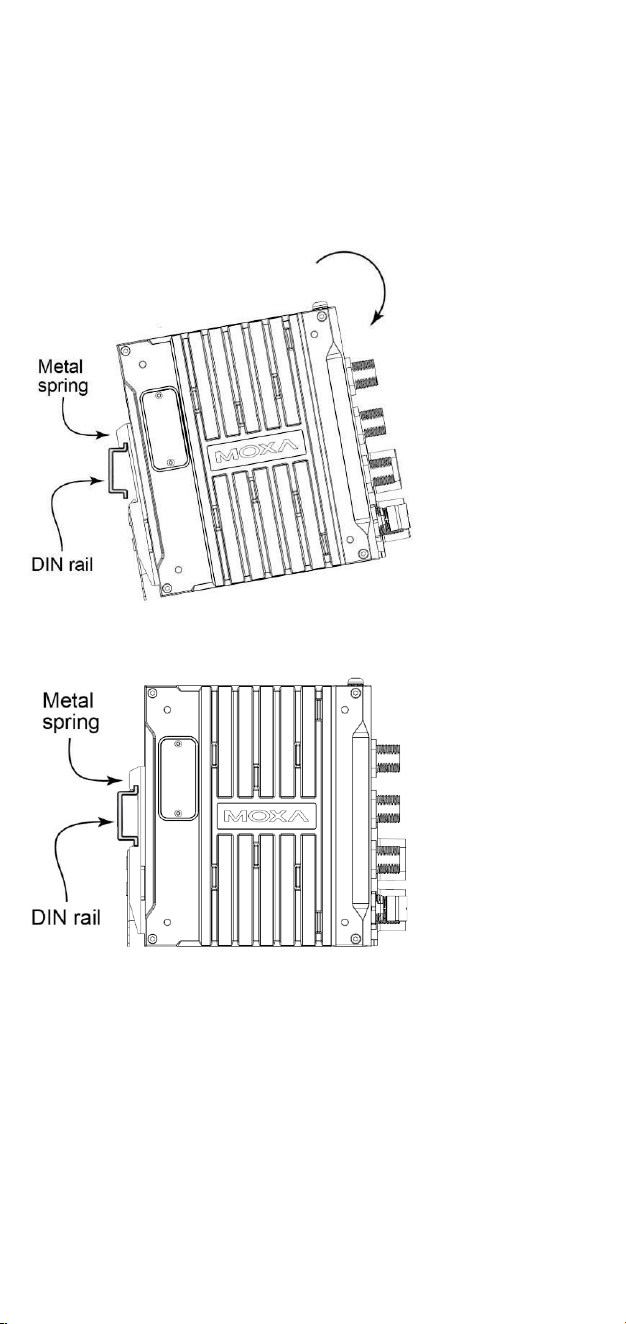
DIN-rail Mounting
Mount the TAP-M310R-SFP Series onto a corrosion-free mounting rail that
adheres to the EN 60715 standard by following the steps below.
STEP 1: Attach the DIN-rail kit to the TAP-M310R-SFP using M4x7mm
screws.
STEP 2: Insert the upper lip of the DIN-rail kit into the mounting rail.
STEP 3: Press the TAP-M310R-SFP towards the mounting rail until it
snaps into place.
To remove the TAP-M310R-SFP Series from a DIN rail, do the following:
STEP 1: Using a screwdriver, pull down the latch on the DIN-rail kit.
STEP 2: Slightly pull the device.
STEP 3: Lift the device up to remove it from the mounting rail.
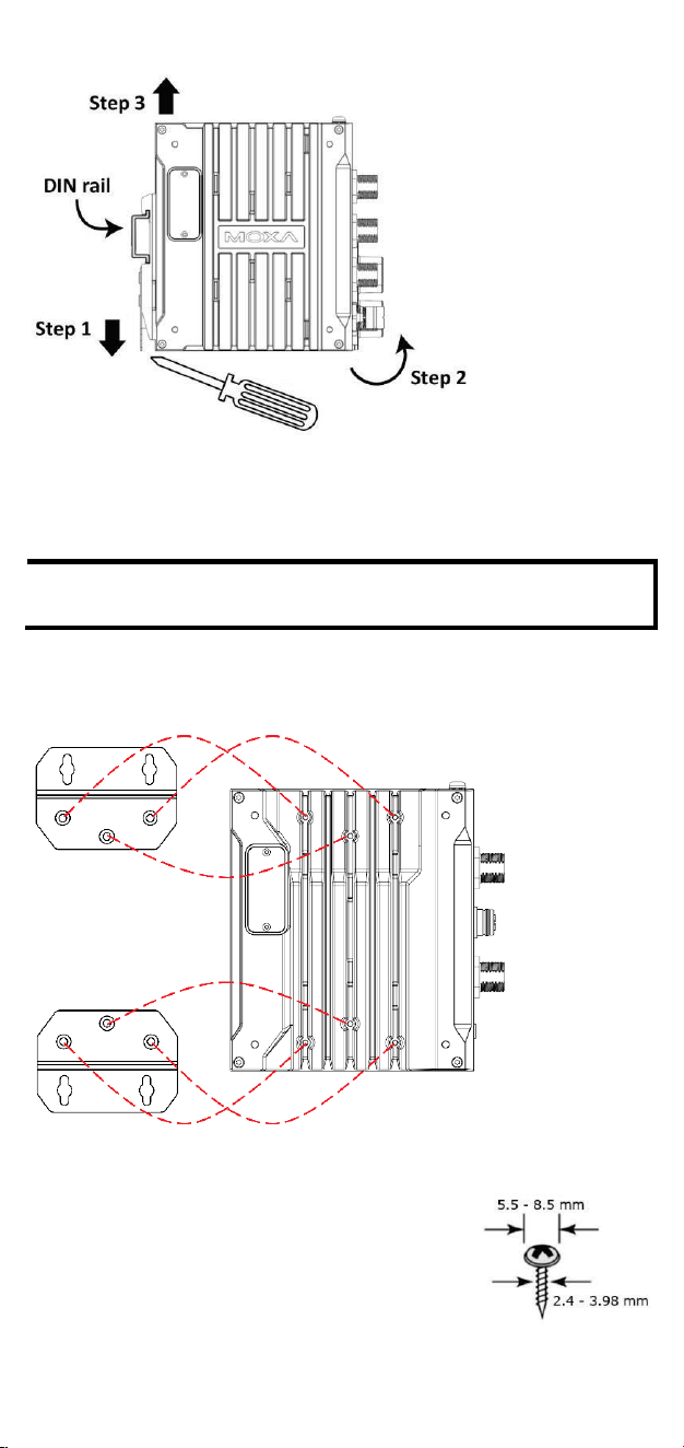
- 5 -
Wall Mounting
For some applications, it may be more convenient to mount the TAP-
M310R-SFP Series to a wall.
NOTE
Wall mounting is optional and must be purchased
separately.
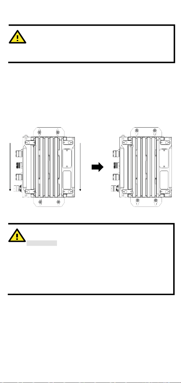
STEP 1: If installed, remove the DIN-rail attachment plate from the
device first. Attach the wall-mounting plates using the six M3x8mm
screws included in the wall mounting kit.
STEP 2: Mounting the TAP-M310R-SFP Series to a
wall requires 4 screws. Use the device with the
wall-mounting plates attached as a guide to mark
the location of the 4 screws on the wall. The heads
of the screws should be between 5.5 mm and 8.5
mm in diameter. The screw shank should be
between
2.4 to 3.98 mm in diameter. The screw length
should be at least 15.0 mm, as shown in the figure
on the right.
- 6 -
WARNING
Safety First!
Be sure to disconnect the power cord before installing and/or
wiring your Moxa TAP-M310R-SFP.
Calculate the maximum possible current in each power wire
and common wire. Observe all electrical codes dictating the
maximum current allowable for each wire size. If the current
goes above the maximum ratings, the wiring could overheat,
causing serious damage to your equipment.
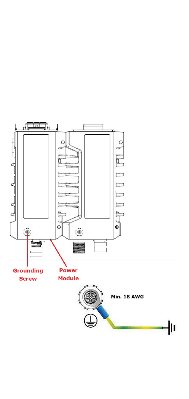
STEP 3: Drill the holes into the wall on the marked locations, leaving
about 2 mm of space between the bottom side of the screw head and
the wall to allow room for sliding the wall-mounting kit between the wall
and the screws.
STEP 4: Once the screws are fixed into the wall, insert the four screw
heads through the large opening of the keyhole-shaped apertures of
the mounting kit, and then slide the TAP device downwards. Tighten the
four screws for added stability.
Wiring Requirements
Read and Follow These Guidelines:
• Use separate paths to route wiring for power and devices. If power
wiring and device wiring paths must cross, make sure the wires are
perpendicular at the crossing point.
• Do not run signal or communications wiring and power wiring
through the same wire conduit. To avoid interference, wires with
different signal characteristics should be routed separately.
• You can use the type of signal transmitted through a wire to
determine which wires should be kept separate. The rule of thumb
ATTENTION
Test the screw head and shank size by inserting the screws into
one of the keyhole shaped apertures of the wall-mounting
plates before attaching the plates to the wall.
- 7 -
is that wiring that shares similar electrical characteristics can be
bundled together.
• Keep input wiring and output wiring separated.
• For future reference, you should label the wiring used for all of your
devices.
Grounding the Moxa TAP-M310R-SFP
Grounding and wire routing help limit the effects of noise due to
electromagnetic interference (EMI). Run the ground connection from
the ground screw to the grounding surface prior to connecting devices
to the TAP-M310R-SFP device.
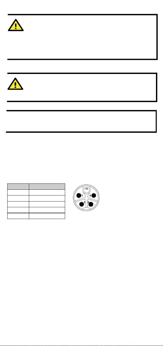
The TAP-M310R-SFP should be well-grounded to ensure safe operation.
Connect the grounding wire to the grounding screw located on the top
panel of the power module.
- 8 -
ATTENTION
Before connecting the TAP-M310R-SFP Series to the power
input, make sure the power source voltage is stable.
Connecting the Power Inputs
NOTE
We recommend installing a power insulation device between
the TAP-M310R-SFP Series and the power source to avoid
damage from power surges.
STEP 1: Connect the power cord connector to the power input port.
STEP 2: Screw the support nuts on the power cord connector to ensure
a tight connection.TAP-M310R-1PSFP models:
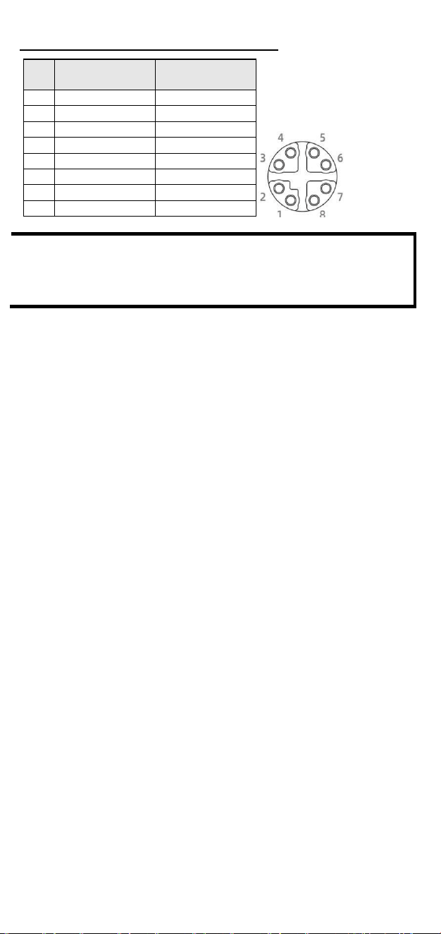
110 to 220 VAC power input: M12 K-coded 5-pin male connector on the
power module’s front panel for the AC power input.
AC Power input port pinouts:
Communication Connections
10/100/1000/2500BaseT(X) Ethernet Ports
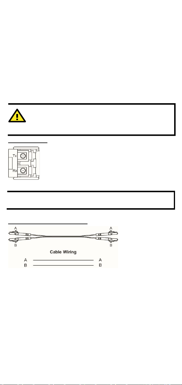
The TAP-M310R-SFP has one 10/100/1000/2500BaseT(X) Ethernet
port (LAN1) on the front panel for connecting Ethernet-enabled
devices. The ports use M12 X-coded 8-pin female connectors. Most
users configure these ports for Auto MDI/MDI-X mode, in which case
the port’s pinouts are adjusted automatically depending on the type of
Ethernet cable used (straight-through or cross-over), and the type of
device (NIC-type or HUB/switch-type) connected to the port.
ATTENTION
This product is intended to be mounted to a well-grounded
mounting surface, such as a metal panel. The potential
difference between the two ground potentials must be zero. If
the potential difference is NOT zero, the product could be
permanently damaged.
Pin No. AC
1 N.C.
2 N.C.
3 L
4 N
PE GND
- 9 -
10/100/1000/2500BaseT(X) Port Pinouts
NOTE
10/100/1000(/2500)BaseT(X) ports that are not in use should
be covered with A-CAP-M12F-M protective caps. The caps are
included and preinstalled on the TAP-M310R-SFP Series device
out of the box.
Pin
10/100
BaseT(X)
1000/2500
BaseT(X)
1
TD+
DA+
2
TD-
DA-
3
RD+
DB+
4
RD-
DB-
5
N.C.
DD+
6
N.C.
DD-
7
N.C.
DC-
8
N.C.
DC+
- 10 -
ATTENTION
Class 1 Laser optical transceivers must be used with this
device.
1000/2500BaseSFP Fiber Ports
The TAP-M310R-SFP has one 1000/2500BaseSFP port (LAN2) on the
front panel for installing SFP modules (the SFP modules must be
purchased separately). To operate properly, a fiber transceiver must be
used with each SFP module. Unlike electrical signals, optical signals do
not require a circuit to transmit data. To transmit full-duplex optical
signals between two devices (e.g., device 1 and device 2), you need to
run two optical lines between the devices. One optical line is used to
transmit data from device 1 to device 2, and the other optical line is
used to transmit data from device 2 to device 1. Connect the Tx
(transmit) port of device 1 to the Rx (receive) port of device 2, and the
Rx port of device 1 to the Tx port of device 2.
LC-Port Pinouts
NOTE
1000/2500BaseSFP ports that are not in use should be covered
with an IP67-rated plastic cap.
LC-Port to LC-Port Cable Wiring

- 11 -
WARNING
Do not push or apply pressure to the fiber cables directly, as
this may damage the cables.
NOTE
If you would like to swap out an SFP module, power off the
TAP-M310R-SFP before removing the old module and
inserting the new module.
Shielding Fiber Connections
To achieve IP67-rated protection for fiber port connections, use a
compatible Moxa cable gland to ensure proper protection.
NOTE
The protective cable gland is an optional accessory and must be
purchased separately. Refer to the TAP-M310R datasheet on
http://www.moxa.com for a list of supported cable glands.
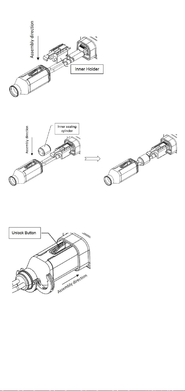
Refer to the following instructions for installing the fiber cable gland.
STEP 1: Use your thumb to press down firmly on the LC latch and
insert the LC plug into the guide cap until the latch is securely in place.
STEP 2: Insert the guide cap with the LC plug through the outer
assembly by holding the guide cap and firmly pushing it into the
assembly.
STEP 3: Once inserted, remove the guide cap and the protective cover
of the fiber optic connector (if installed).
STEP 4: Insert the LC plug into the SFP transceiver port and install the
inner holder onto the cable. Ensure the wires are seated properly in the
wire holding spaces, then secure the inner holder to the LC plug.
- 12 -
STEP 5: Install the inner sealing cylinder, ensuring that the wires are
inserted into the wire gaps. Make sure the inner sealing cylinder
touches the inner holder, leaving no gap.
STEP 6: Slide the outer assembly onto the sealing cylinder and inner
holder until it snaps into place.
STEP 7: Place the outer snap ring over the rubber flange of the outer
assembly and close the ring. Use pliers to tighten the outer snap ring
around the assembly.
Console Connection
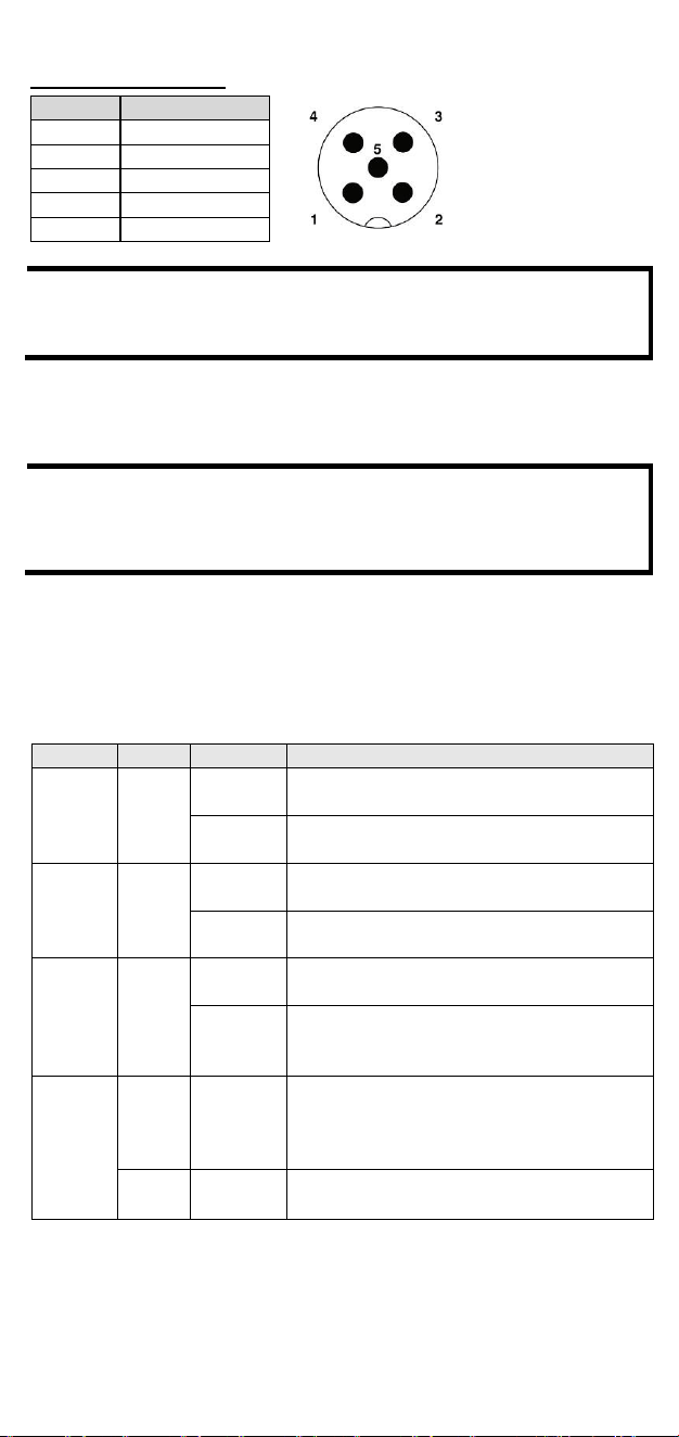
The TAP-M310R-SFP Series has one M12 A-coded 5-pin male console port
located on the front panel. Use an M12 A-coded 5-pin female cable to
connect the TAP-M310R-SFP’s console port to your PC’s COM port. Use a
program to access the console configuration on the TAP-M310R-SFP.
- 13 -
Pin No.
Con.
1
TX.
2
RX
3
DSR
4
GND
5
DTR
Console Port Pinouts
NOTE
When the console port is not in use, cover it with an A-CAP-
M12M-M protective cap. The cap is included and preinstalled on
the TAP-M310R-SFP Series device out of the box.
Antenna Connection
There are four N-type RF connectors on the front panel. The
connectors on the front panel are labeled 1A, 1B, 2A, and 2B.
NOTE
Antenna connectors that are not in use should be covered with
A-CAP-NM-MIP67 protective caps. The caps are included and
preinstalled on the TAP-M310R-SFP Series device out of the
box.
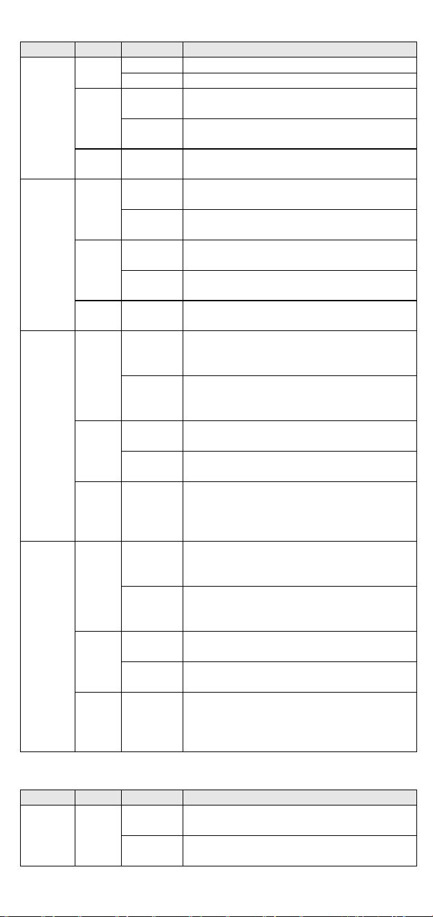
LED Indicators
The front panel of each module contains several LED indicators. The
function of each LED is described in the table below.
Radio Module
LED
Color
State
Description
PWR L
Green
On
Power is being supplied from a power
module on the left side (if any).
Off
Power is not being supplied from a power
module on the left side.
PWR R
Green
On
Power is being supplied from a power
module on the right side (if any).
Off
Power is not being supplied from a power
module on the right side.
PWR
Green
On
Power is being supplied to the 24 VDC
input of the radio module.
Off
Power is not being supplied via the 24
VDC input of the radio module, or the
switch module is present.
SYS
Red
On
Indicates a system initialization failure,
configuration error, or system error. This
LED will be off during the regular boot up
process.
Green
On
System startup is complete, and the
system is operating normally.
- 14 -
LED
Color
State
Description
LAN1
Green
On
The LAN port’s 2500 Mbps link is active.
Blinking
Data is being transmitted at 2500 Mbps.
Amber
On
The LAN port’s 10/100/1000 Mbps link is
active.
Blinking
Data is being transmitted at 10/100/1000
Mbps
Green/
Amber
Off
The LAN port is inactive.
LAN2
Green
On
The LAN port’s 2500 Mbps link is active.
Blinking
Data is being transmitted at 2500 Mbps.
Amber
On
The LAN port’s 10/100/1000 Mbps link is
active.
Blinking
Data is being transmitted at 10/100/1000
Mbps
Green/
Amber
Off
The LAN port is inactive.
2.4G
Green
On
The device is in Client(-router) or Slave
mode and an active link is established to
an AP or master on the 2.4 GHz band.
Blinking
Traffic is being transmitted in Client(-
router) or Slave mode over the 2.4 GHz
band.
Amber
On
The device is in AP, Master, Sniffer mode
and the 2.4 GHz band is active.
Blinking
Traffic is being transmitted in AP or
Master mode over the 2.4 GHz band.
Green/
Amber
Off
The 2.4 GHz band is disabled, not
working properly, or the device is in
Client(-router) or Slave mode without a
connection to an AP or Master.
5G
Green
On
The device is in Client(-router) or Slave
mode and an active link is established to
an AP or master on the 5 GHz band.
Blinking
Traffic is being transmitted in Client(-
router) or Slave mode over the 5 GHz
band.
Amber
On
The device is in AP, Master, or Sniffer
mode and the 5 GHz band is active.
Blinking
Traffic is being transmitted in AP or
Master mode over the 5 GHz band.
Green/
Amber
Off
The 5 GHz band is disabled, not working
properly, or the device is in Client(-
router)/Slave mode without a connection
to an AP or Master.
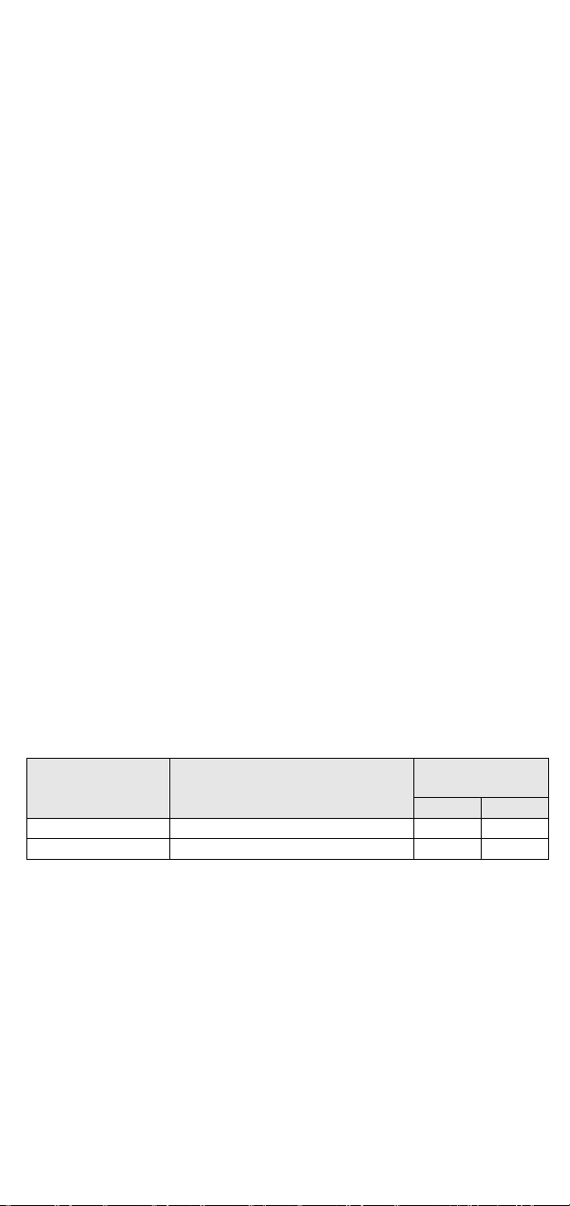
Power Module
LED
Color
State
Description
PWR
Green
On
The power module is active and supplying
power.
Off
The power module is idle and not
supplying power.
- 15 -
Certifications
FCC Statement
Federal Communication Commission Interference Statement
This equipment has been tested and found to comply with the limits for
a Class A digital device, pursuant to part 15 of FCC Rules. These limits
are designed to provide reasonable protection against harmful
interference when the equipment is operated in a commercial
environment. This equipment generates, uses, and can radiate radio
frequency energy and, if not installed and used in a accordance with
the instruction manual, may cause harmful interference to radio
communications. Operation of this equipment in a residential area is
likely to cause harmful interference in which case the user will be
required to correct the interference at his own expense.
This device complies with part 15 of the FCC Rules. Operation is subject
to the following two conditions:
(1) This device may not cause harmful interference, and
(2) his device must accept any interference received, including
interference that may cause undesired operation.
Caution
Any changes or modifications not expressly approved by the grantee of
this device could void the user's authority to operate the equipment.
FCC Radiation Exposure Statement
This equipment complies with FCC radiation exposure limits set forth for
an uncontrolled environment. This equipment should be installed and
operated with a minimum distance of 20 cm between the radiator and
your body.
IMPORTANT NOTE
Antenna Type
Model Number
Antenna Gain
(dBi)
2.4 GHz
5 GHz
Panel
ANT-WDB-PNF-1011
11.00
12.04
Panel
ANT-WSB5-PNF-16
-
16.97
This radio transmitter FCC ID: [SLE-TAP-M310R-SFP] has been approved
by FCC to operate with the antenna types listed below with the
maximum permissible gain and required antenna impedance for each
antenna type indicated. Antenna types not included in this list, having a
gain greater than the maximum gain indicated for that type, are strictly
prohibited for use with this device.
Professional Installation
This is a specific product that requires professional installation and
configuration, must be performed by trained technical engineers to
install the antenna, please contact Moxa for further information.

- 16 -
The availability of some specific channels and / or operational frequency
bands is country-dependent and are firmware-programmed at the
factory to match the intended destination. The firmware settings are
not accessible to the end user.