

User Manual
VG10-B21A
Version: 1.0
Due to the regular upgrades of systems and products, ZKTeco could not guarantee exact
consistency between the actual product and the written information in this manual.
Remark
Please follow the user manual for correct installation and testing. If there
is any doubt please call our tech-supporting and customer center.
Our company applies ourselves to reformation and innovation of our
products. No extra notice for any change. The illustration shown here is
only for reference
. If there is any difference, please take the actual
product as the standard.
The product and batteries must be handled separately from household
waste. When the product reaches the end of service life and needs to be
discarded, please contact the local administrative department and put it
in the designated collection points in order to avoid the damage to the
environment and human health caused by any disposal. We encourage
recycling and reusing the material resources.

CATALOG
Product Picture ...................................................................... 1
Product Features ................................................................... 1
Technical Parameters ............................................................ 1
Operations ............................................................................. 2
Main Interface .................................................................... 2
Call. ..................................................................................... 3
Monitor ............................................................................... 4
Security .............................................................................. 5
Settings .............................................................................. 6
Talk Record ......................................................................... 10
Application ......................................................................... 11
Web Setup .............................................................................. 12
Network Settings ............................................................... 12
Room No. Settings ............................................................. 13
VOIP .................................................................................... 13
Advanced Settings ............................................................. 14
Webkit Settings .................................................................. 16
Other Settings .................................................................... 16

License Settings .................................................................. 17
Logout ................................................................................. 18
System Configuration ............................................................ 19
System Diagram. .................................................................... 20
Installation. ............................................................................. 21
Troubleshooting. .................................................................... 22
Safety Precaution. .................................................................. 23

-1-
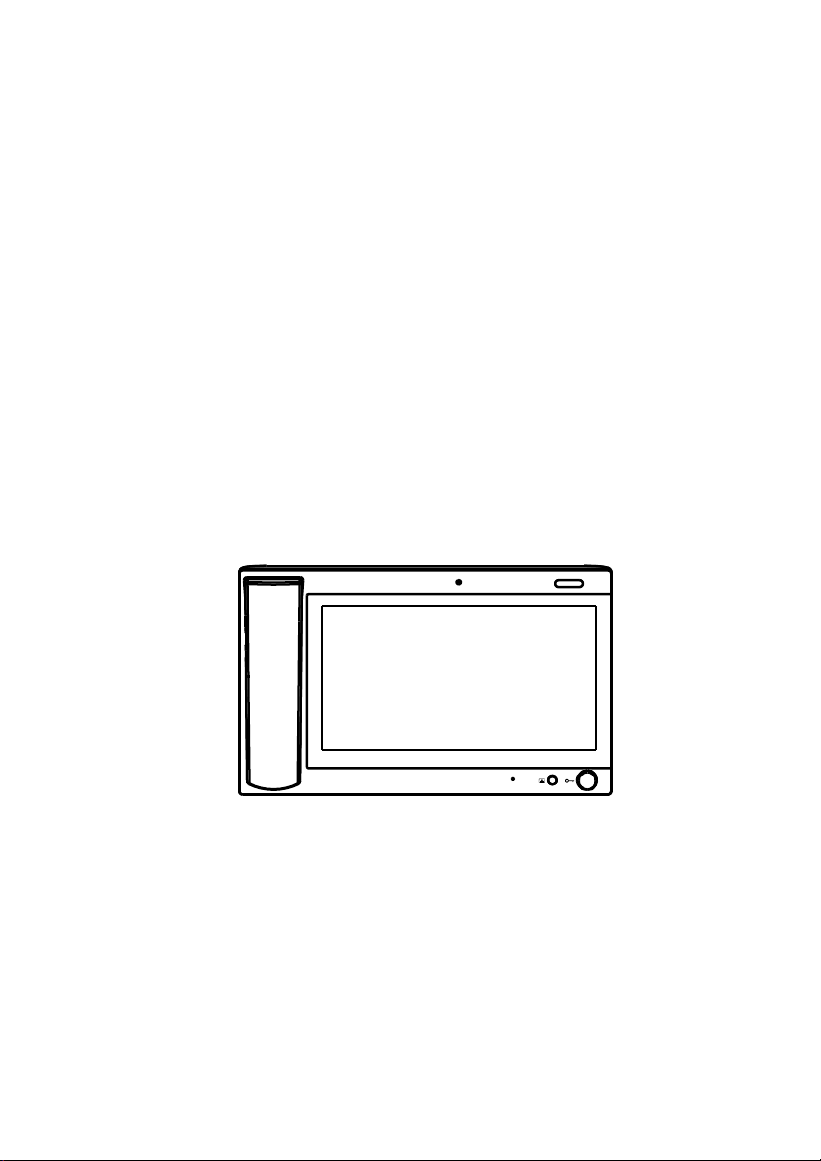
Product Picture
Camera
Power LED
Unlocking
Product Features
1. Two-way communication with indoor monitor;
2. Monitor wall panel and unit panel;
3. Alarm and intercom information can be recorded;
4. Automatic message and answering can be set;
Technical Parameters
1.
Rated voltage: DC12V
2.
Rated power: 10W
3.
Standby power consumption: 3W
4.
Display screen: 10.1 Inch display
5.
Resolution:1024*600
6.
Operating temperature: -10℃~+55℃
7.
Relative humidity: 20%~80%
8.
CPU frequency: Quad core 1.3Ghz
9.
Memory: 512MB
10.
Flash: 4GB
11.
Maximum SD card capacity: 32G
-2-
Operations
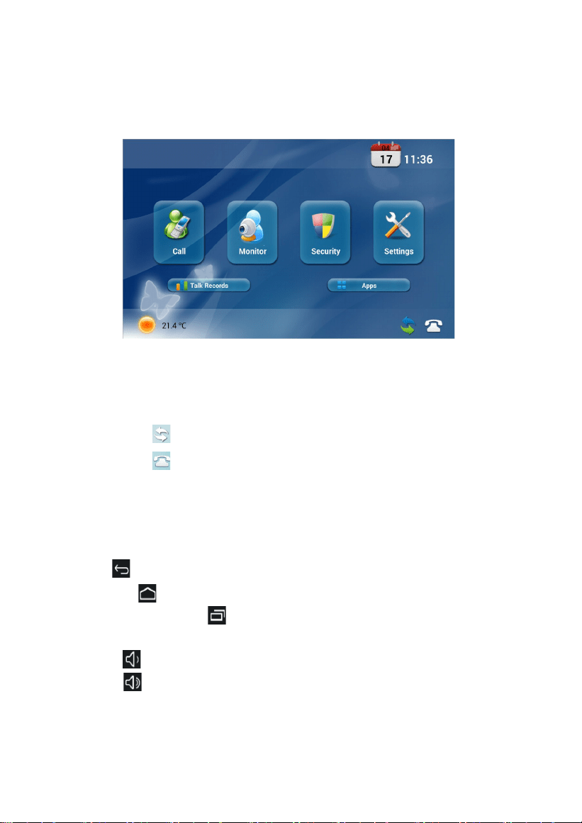
Main interface
Main menu: call, monitor, security, system settings, talk records and Apps. Status bar:
network status, SIP registration.
Status bar description:
1.
Network status : When there is a network connection, the icon is always on;
2.
SIP registration : When the SIP registration is successful, the icon is always on.
After entering the secondary menu, the status bar will be displayed at the bottom of the
screen.
Note:
1. Return : Click the icon to return to previous menu.
2. Home page : Click the icon to return to home page.
3. Background applications : Click the icon, and the interface will show the
applications running in the background.
4. Volume- : Click the icon to reduce the current system volume.
5. Volume+ : Click the icon to increase the current system volume.
-3-
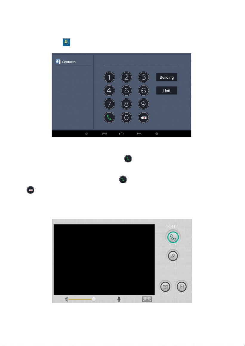
1.1 Call
Clicking the icon , the system will enter into the following interface:
Input building No. of 1-4 digits+ “Building” icon + unit No. of 1-2 digits + “Unit” icon+ room
No. of 1-4 digits (floor No. included), then click icon to call.
For example, if you want to call indoor monitor :0001010807, input 1+ “Buliding” , then 1+ “Unit”
+ 08(floor No.) +07(room No.) and click icon to call. If the input is incorrect, click the icon
to delete.
After successful call, the user will see the interface as shown below:
-4-
When the call is answered, call status is as below:
①If the called indoor monitor has a camera, the image of called party will be displayed in the
management center.
②At the same time, the video of indoor monitor is transmitted to management center.
When there is a call from outdoor panel, wall panel, indoor monitor or secondary
outdoor panel, the management center will ring; If no one answers within 25 seconds,
the system will give up the call.
Click the icon to talk to outdoor panel; Click the icon to end this call; Click the
icon to unlock the door for visitors.
Audio and video recording can be realized during the call (TF card should be inserted
into management center).
Click the icon to capture the visitor's image; Click the icon , the system will
record and save the video image of current call.
The default calling time is 120 seconds.
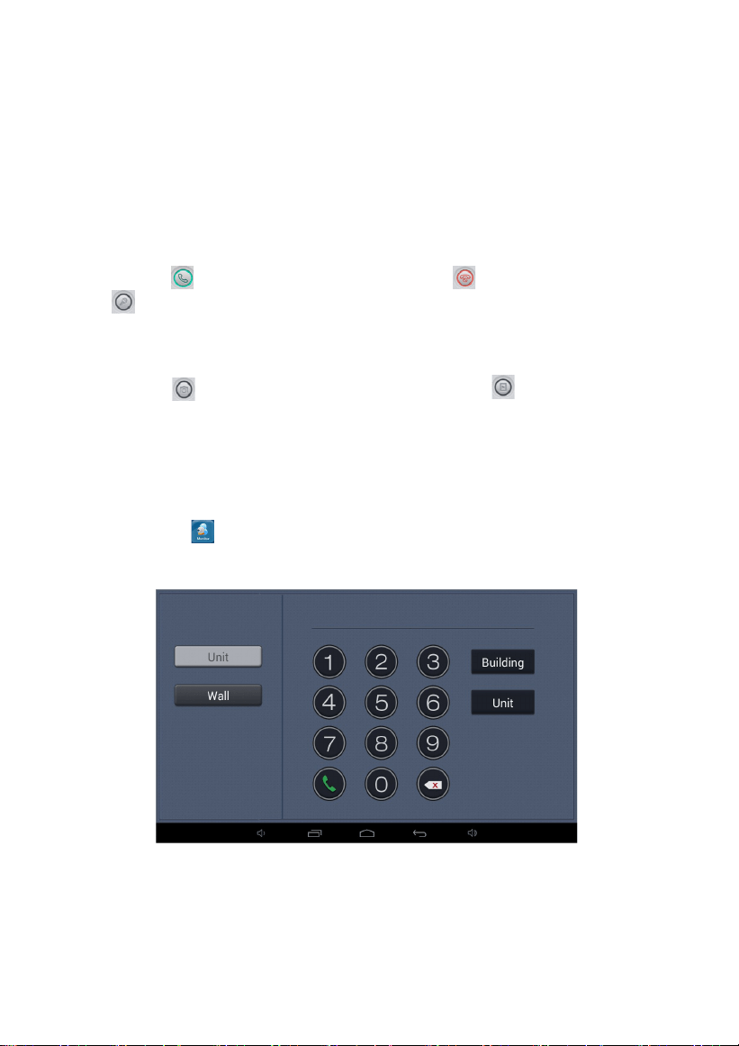
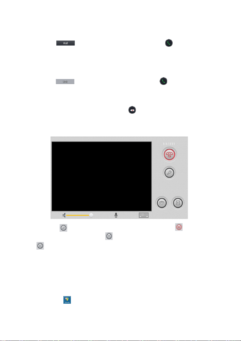
1.2 Monitor
Clicking the icon on the main interface, the system will enter the interface as shown
below:
-5-
1.2.1
Monitor Wall Panel
Click the icon , enter two digits, and then click the icon to monitor wall
panel.
1.2.2
Monitor Unit Panel
Click the icon , enter 7 digits, and then click the icon to
monitor unit
panel. The first four digits are building No., the following two digits are unit
number, and the last one is the number of outdoor panel.
In case of input error, you can click the icon to delete the numbers or click the
"*" icon to delete all numbers. The monitoring system will enter the interface as
shown below:
Click the icon to unlock the door for visitors; Click the icon to end the
current monitoring; Click the icon to capture the visitor's image; Click the
icon , the system will record and save the video image in the current call
monitoring .The current volume can also be adjusted.
The default monitoring time is 120 seconds.
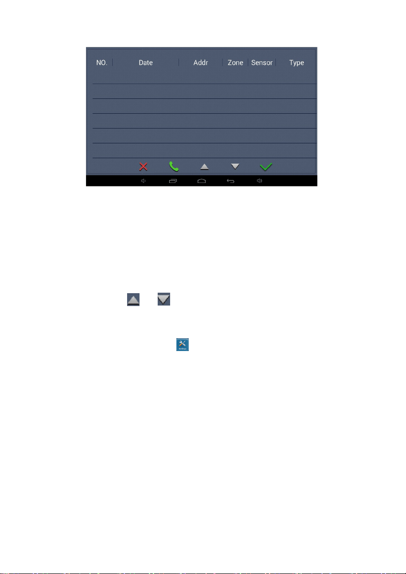
1.3 Security
Clicking the icon on the main interface, the system will enter into the following
interface:
-6-
This interface records the alarm information sent by indoor monitor to the
management center machine.
When indoor monitor gives an alarm, the interface will display the alarm address and
alarm type, and the current record will be displayed in red. Click the alarm processing
icon, the record will be displayed in black and saved in the alarm record list. Select a
record and click the callback icon, the system will automatically call indoor monitor that
sends the record; Click and icon to switch between pages.
1.4 Settings
On the main interface, click the icon to enter the system configuration
interface.
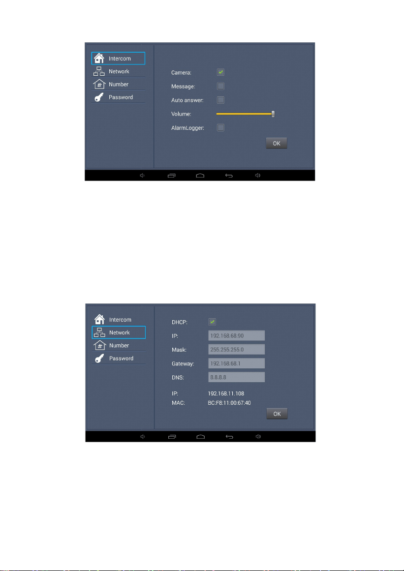
1.4.1
Intercom
Clicking "intercom" icon, and the system will enter the interface as shown
below:
-7-
If you want to enable the functions of camera, automatic message, automatic
answering and alarm logger, check the boxes, swipe left and right to adjust the
intercom volume, and then click "OK" icon.
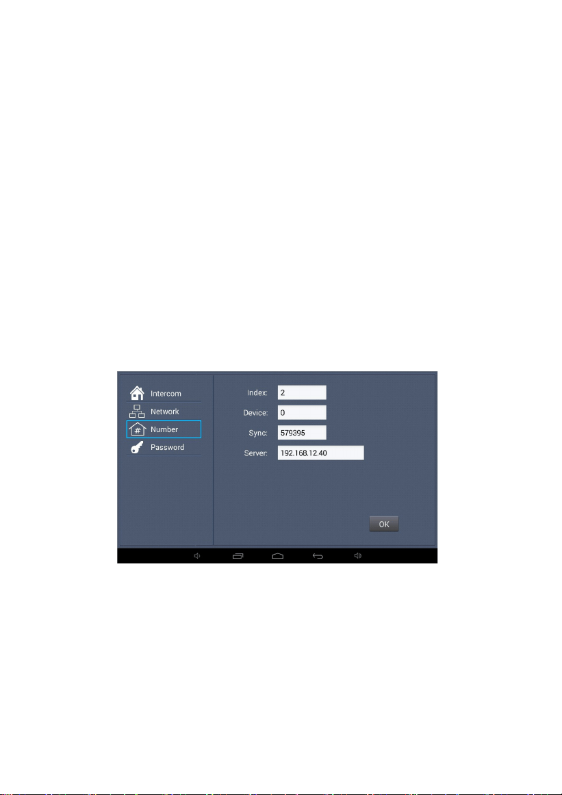
1.4.2
Network Settings
Clicking "Network", admin password window will pop up. Enter the admin
password and click ok. The system will enter the interface as shown below:
-8-
DHCP: When enabled, the router automatically allocates the IP address.
IP address: In same network segment of the same system, IP address cannot be
repeated.
Subnet mask: The original subnet mask is 255.255.255.0 and does not need to be
changed. If the user needs to make changes, click the setting box next to the
item, enter the content to be set through the numeric keypad that pops up, and
then click "OK" icon.
Default gateway: Fill in according to IP segment assignment on site. DNS server:
Refers to the IP address of the DNS server.
Current IP: The system will automatically display IP address of management
center.
1.4.3
Number Settings
Clicking "Number", and the system will enter the interface as shown below:
-9-
Index: the number of management center, which can be up to 2 digits.
Device code: when the device code is set to 0, the management center is the
main management center; When the device code is 1 to 4, it is the sub
management center. When indoor monitor calls the management center, five
management centers will ring at the same time. If the device codes of all the 5
management center are set to 0 but the indexes are set to 1 to 5, when indoor
monitor calls the management center, if the first management center is
disconnected or busy, the call will automatically transfer to next management
center.
Sync code: please change the sync code as soon as possible. The
synchronization code is used to synchronize the main and sub management
centers. The main and sub management centers can be synchronized only
when their sync codes are consistent.
Server: IP address or domain name of server.
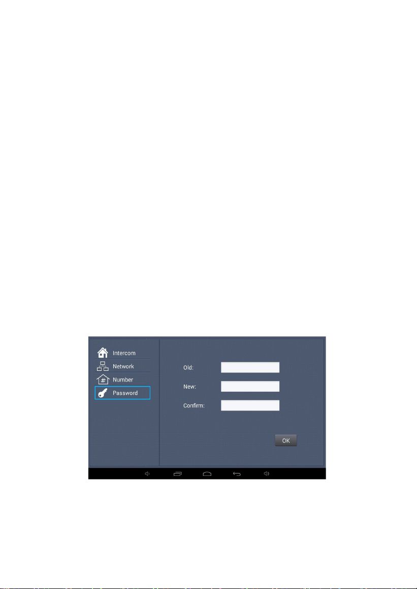
1.4.4
Password
Clicking "Password", the system will enter the interface as shown below:
-10-
Click the input box after the old password, enter the original password through
the numeric keypad that pops up,
enter the new six-digit password in the
same way and then re-enter the password in the box next to the item "Confirm".
Clicking "OK", the system will emit a beep.
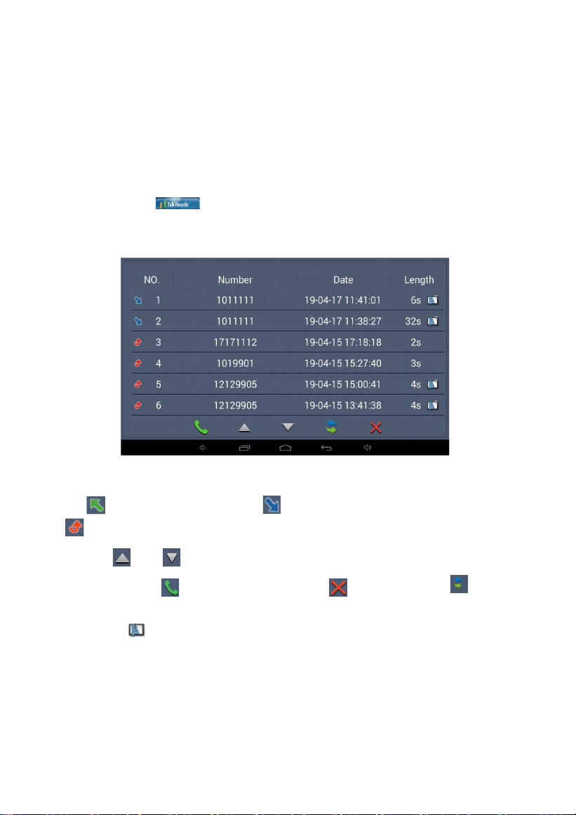
1.5 Talk Records
Clicking the icon on the main interface, the system will enter the
interface as shown below:
The page lists the intercom records of the management center.
refers to the outgoing call; refers to the incoming call;
indicates the missed call. It can save up to 64 records.
Click the and icon to scroll up and down the record. Select one
record
and click the icon to call back; Click the icon to delete it; Click
to make
a backup .If there is a snapshot, a small icon will be displayed
at the end of the
record. Click to view the picture.
-11-
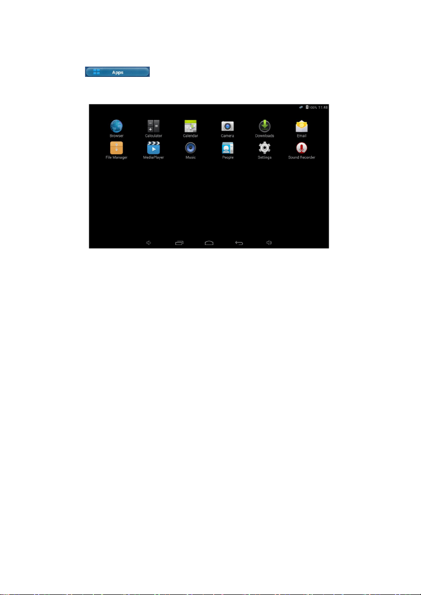
1.6 Application
Click icon on the main interface to enter into application
function
interface.
Gadgets: Email, Calculator, Peoples (Contacts), Sound Recorder, Calendar, Camera,
Music, etc.
Data storage: Media Player, File Manager, Downloads.
Extended application: you can download the software you need from the
browser.
Settings: you can view the version information of the device, and can also set
the ringtone, brightness and some related auxiliary functions of the device.
-12-
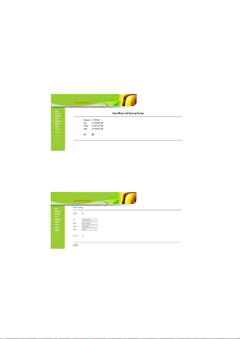
Web Setup
Connect the management center and the computer by the switch, input the IP
address of the management center on the computer web browser (IP address
of the computer and management center must be in the same network
segment), then input the user name and password (the default user name of
the system is "admin", and the password is "123456") to enter the interface:
2.1
Network Settings
Click the icon "Network", and the system will enter the interface as shown
below:
-13-
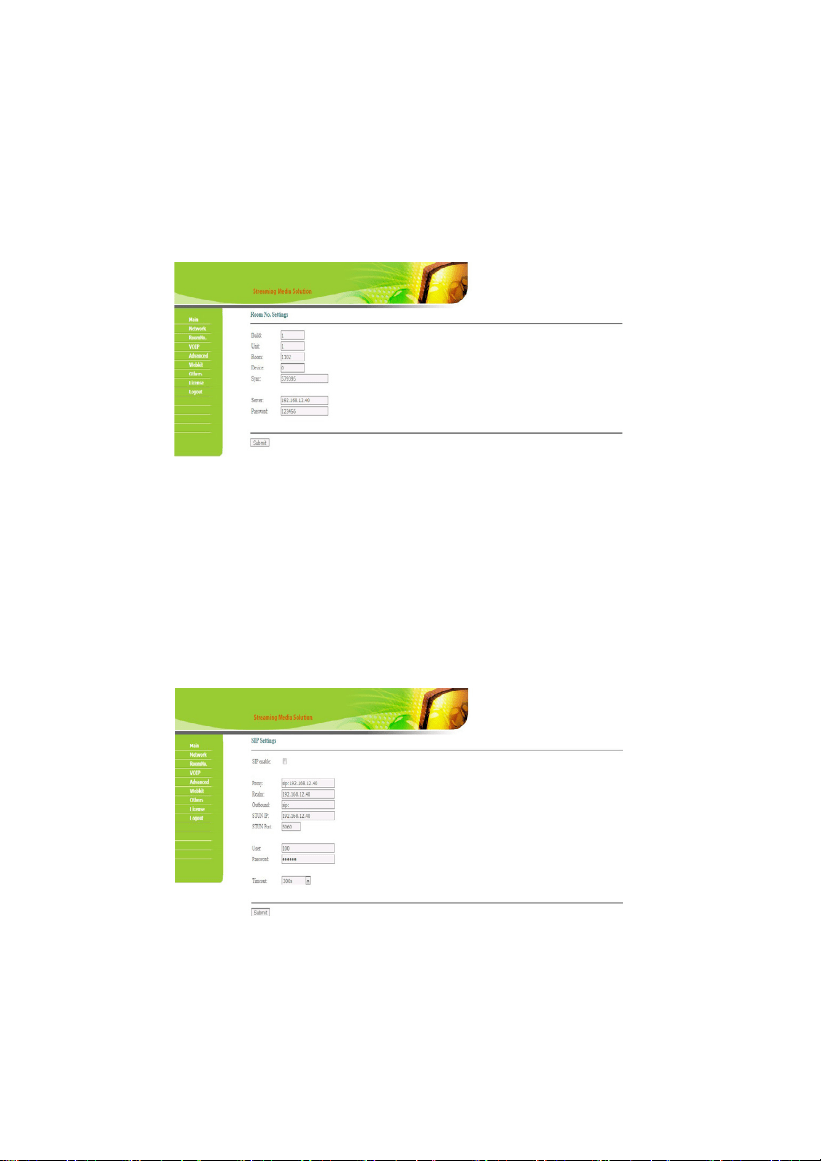
2.2
Room No. Settings
Click the icon "Room No. ", and the system will enter the interface as shown
below:
The settings are the same as the ones of management center. After setup, click
Submit to enable the settings.
2.3
VOIP
Click the icon "VOIP", and the system will enter the interface as shown below:
-14-
The settings are the same as the system settings of management center.
To connect to SIP phone from other manufacturer, please check "SIP enable"
and input the number registered in SIP server in box "User".
Timeout: talking time of management center.
After setup, click Submit to enable the settings.
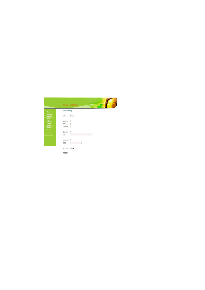
2.4
Advanced Settings
Click the icon "Advanced", and the system will enter the interface as shown below:
Ex Phone: Input IP address of other manufacturer’s SIP device. It refers to other
factory’s VOIP device which is used as sub management center. When outdoor
panel calls management center, SIP device will ring at the same time. Other
terminals will stop ringing when one of the management center or SIP device
answers the call. The user can enter the SIP address of the other factory's SIP
phone in the URL box.

-15-
Auto Pickup: checking the box, the management center will automatically
answer the call, when outdoor panel calls but there is no answer within 10s.
Deaf-mute mode: Check the box to enable this function, that is, when calling the
management center, the light connected to the alarm interface of the
management center will flicker directly.
Quick call: Check the box to enable this function, that is, designate the call to
management center or other device. Fill in the SIP address of the designated
device in the URL box. It can be an indoor monitor or SIP network phone from
other manufacturers.
DTMF unlock: Check the box to enable this function, that is, if outdoor panel from
docking factory can unlock the door with the code "#", please enter "#" in the box.
After setup, click Submit to enable the settings.
-16-
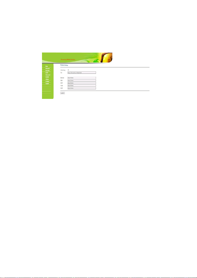
2.5
Webkit Settings
Click the icon "Webkit", and the system will enter the interface as shown below:
Advertising: link to the WEB page, make the WEB page into the form of picture
playing, and play it when the management center is in standby mode.
Browser: this item is invalid.
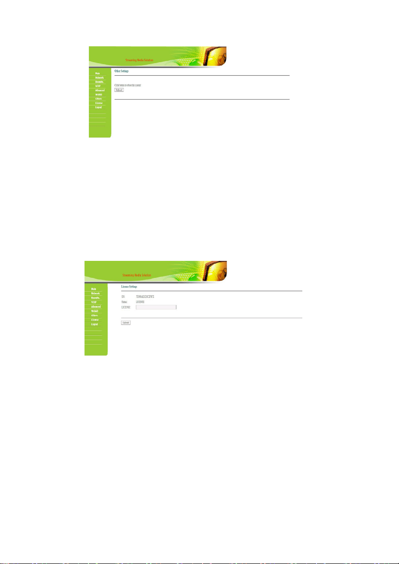
2.6
Other Settings
Click the icon "Other", and the system will enter the interface as shown below:
-17-
Click "Reboot" to reboot the system.
2.7
License Settings
Click the "License" icon, and the system will enter the interface as shown below:
Input the code in "LICENSE" and click "Submit" to enter the above interface.

-18-
2.8
Logout
Click the icon "logout", and the system will enter the interface as shown below:
Click "Submit" to log out of the system.
-19-
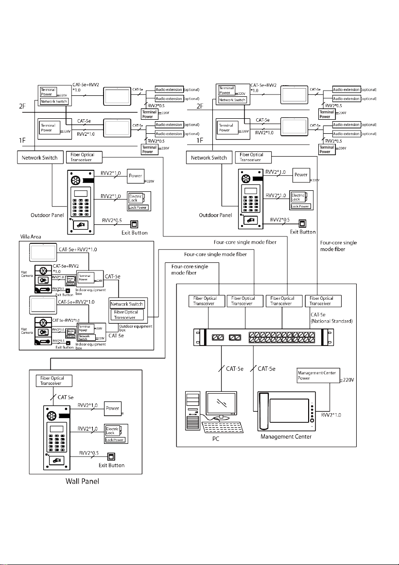
System Configuration
-20-
CAT-5e
System Diagram
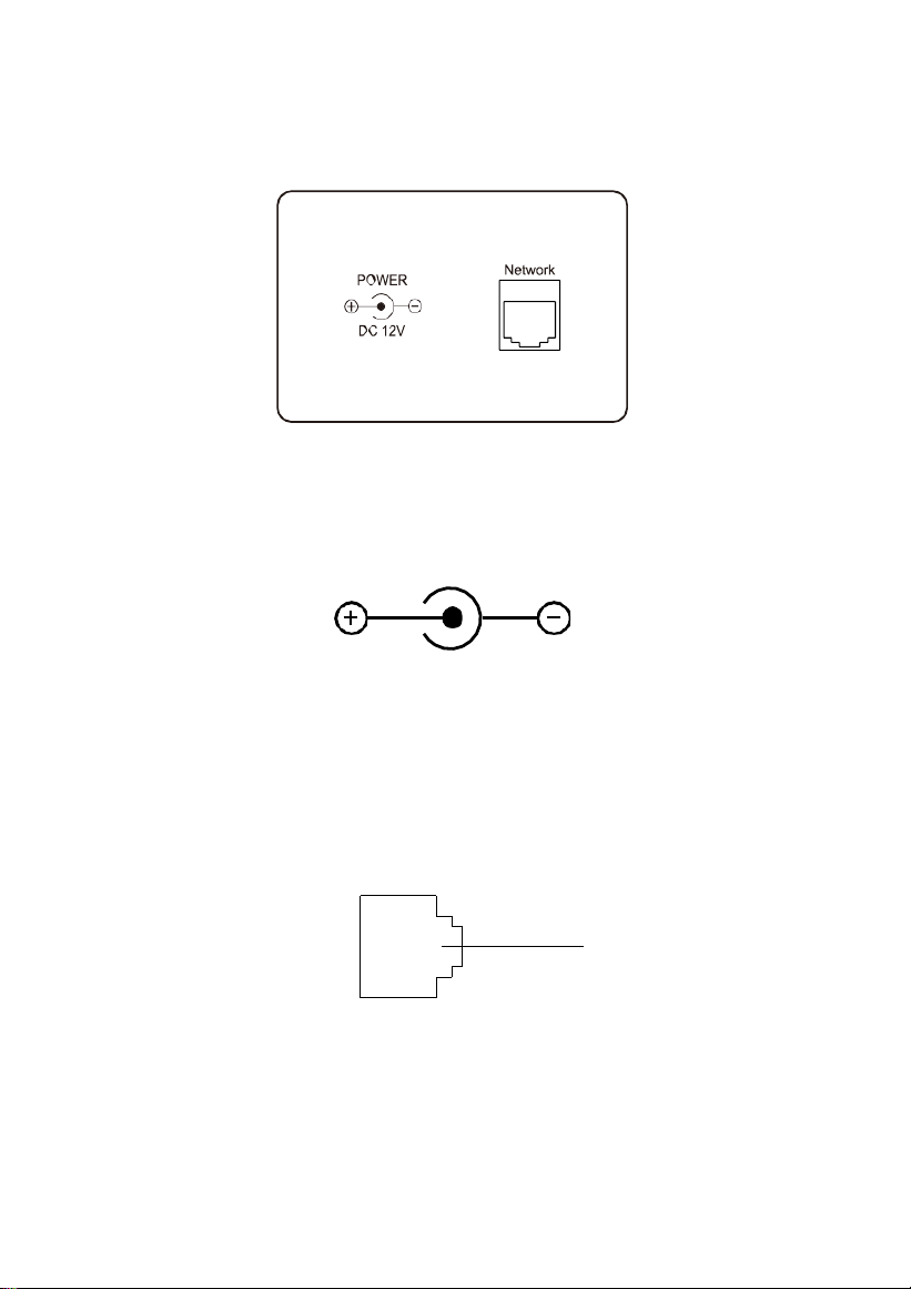
5.1
Power Interface
Power Input Interface of Management Center: connect with 12V DC power
supply.
Power Interface
5.2
Network Interface
Connect to outdoor panel, indoor monitor or other network device through a
switch.
With POE function, POE switch can be connected to supply power to management center.
Network Interface
-21-
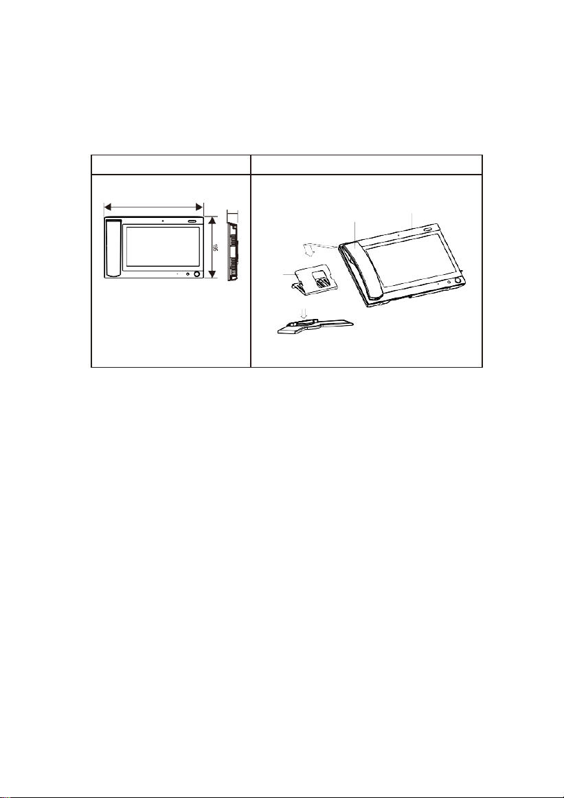
Installation
Model: VG10-B21A
Size and Appearance
Installation
diagram
303
Product size: 303*195*35mm
Installation: desktop installation
35
3.Stand
Step2
4.Base
Step
1
2.Handset
1.Mainframe

-22-
Troubleshooting
Some common failures and troubleshooting methods are listed for your reference. In
case of failure that cannot be repaired, do not disassemble or repair the product by
yourself. Please contact the after-sales service department.
The machine cannot be turned on or automatically shut down.
Check if the power supply is off and power it on again.
The screen is dim.
Check whether the screen brightness and contrast settings are correct.
No voice from management center during the call.
Check if management center is set as mute mode or if the volume is set to minimum.
Management center cannot monitor outdoor panel.
The system is in use by other users.
The multimedia file does not play properly.
Check whether the system supports the file format. Please refer to the multimedia
settings.
The touch screen has slow response or is insensitive.
Remove any protective film from the touch screen, which may affect the identification or
input of the device.
Make sure your fingers are dry and clean when you touch the touch screen.
Restart the device to clear any temporary software errors.
Device temperature is high.
The high temperature is due to the long-term use of the equipment, which is normal
and will not affect the service life or performance of the equipment.

-23-
Safety Precaution
In order to protect you and others from harm or your device from damage, please read the
following information before using the device.
Do not install the device in the following places:
Do not install the device in high-temperature and moist environment or the area
close to magnetic field, such as the electric generator, transformer or magnet.
Do not place the device near the heating products such as electric heater or the fluid
container.
Do not place the device in the sunshine or near the heat source. This might
cause discoloration or deformation of the device.
Do not install the device in an unstable position to avoid the property losses or
personal injury caused by the falling of device.
Guard against electric shock, fire and explosion
Do not use damaged power cord, plug or loose outlet.
Do not touch the power cord with wet hands or unplug the power cord by
pulling.
Do not bend or damage the power cord.
Do not touch the device with wet hands.
Do not make the power supply slip or cause the impact.
Do not use the power supply without the manufacturer's approval.
Do not have the liquids such as water go into the device.
Clean Device Surface
Clean the device surfaces with soft cloth dipped in some water, and then rub the
surface with dry cloth.
Other Tips
In order to prevent damage to the paint layer or the case, please do not expose the
device to chemical products, such as the diluent, gasoline, alcohol, insect-resist
agents, opacifying agent and insecticide.
Do not knock on the device with hard objects.
Do not press the screen surface. Overexertion might cause flopover or damage to
the device.
Please be careful when standing up from under the device.
Do not disassemble, repair or modify the device at your own discretion. The
arbitrary modification is not covered under warranty. When any repair required,
please contact the customer service center.
If there is abnormal sound, smell or fume in the device, please unplug the
power cord immediately and contact the customer service center.
When the device isn’t used for a long time, the adaptor and memory card can be
removed and placed in dry environment.
When moving, please hand over the manual to new tenant for proper usage of the
device.

-24-
ZKTeco Industrial Park, No. 32, Industrial Road,
Tangxia Town, Dongguan, China.
Phone : +86 769 - 82109991
Fax : +86 755 - 89602394
www.zkteco.com
Copyright © 2024 ZKTECO CO., LTD. All Rights Reserved.


