
-1-
When installing and using this electrical equipment, basic safety precautions should
always be followed, including the following:
These instructions are for
correct installation, and optimum performance of the Bath pumps, so
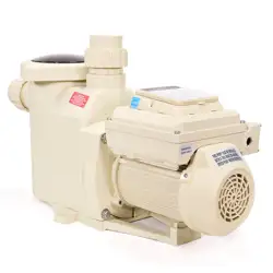
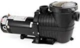
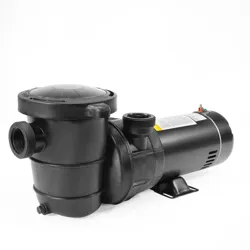
they should be read carefully. These are single-stage centrifugal pumps designed to
operate with compact hydro-massage equipment, They are equipped with a total-emptying
system to prevent the discharge of residual liquid in each stopping.
These units are designed to operate with clean water at a maximum water temperature of
50
°
C.
Built of top quality materials, they are subjected to strict hydraulic and electrical controls and are
carefully verified. Correct installation is ensured by following these instructions and those of
the wiring diagram; otherwise, over loads may be produced in the motor. We decline
responsibility for any damage caused by not following these instructions.

-2-
The pumps should be inst
alled horizontally, securing them with screws through the holes in
the supports to prevent undesirable noise and vibration.The suction, pipe of lhe pump
should be as short as possible. The rating Label must be visible aer installation. Parts
coutaining live parts, except parts supplied with safety extra low voltage<12V, must be
inaccessible to a person in the bath. Class I appliances must be permanently
connected to fixed wiring. Part including electrical components except remote control
devices must be located or fixed so that they cannot into bath.
3.
Pipe Assembly
The suction and discharge pipes should have a diameter equal to or greater than that of the
intake tapping of the pump.
Avoid traps as, in addition to affecting efficiency, they impede total overall emptying.
The suction and discharge pipes should not rest on the pump in any case.
Seal all the connectors and unions well. Avoid any dripping on the motor, which would
unfailingly damage it.
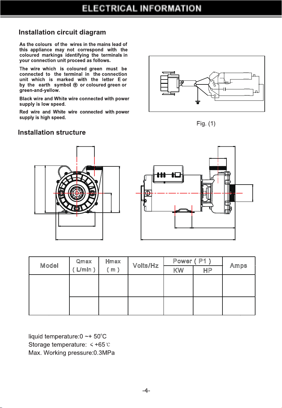
Electrical connection
The electrical install action should have a multiple separation system with contacts opening
at least 3mm.
For continued protection against possible electric shock this unit is to be mounted to the
base in accordance with the installation instructions. The protection of the system should be
based on a residual current device (RCD) with a rated tripping current not exceeding
30mA. The supply cable should comply with EMC standards (2).Single-phase motors have
built-in thermal protectoy. When the pump run under abnormal condition and caused the
thermal protector to work, please cut o the pump power if it is at the low speed (1450r/min)
and plug in 1 minute later. If the pump is at the high speed (2900r/min), it will start work
again when the thermal protector reset automatically as the motor temperature drops to a
certain degree. The diagrams in Fig. (1) correct electrical connection. The electric
connection must be carried out by qualified sta following strictly the "UL 1563, UL 1081"
standard. Be sure that the grounding connection is correctly made.The grounding conductor
shall not be smaller than NO.12AWG(3.3mm
2
)
Be sure that the equipotential connection
between the bath and the pump is correctly made. Wires serving as equipotential bonding
conductors shall have a cross sectional area between 2.5 and 6mm
1
and shall be equipped
with the terminal suitable receptacle.
Controls Prior to Initial Start-up
Verify that the pump shaft turns freely.
Ch
eck that the mains voltage and frequency are according to the name plate.
The hydro-massage assembly should be equipped with a system to prevent the pump from
starting up if a minimum water level is not present.
Check the rotating direction of the motor, which should concur with that indicated on the fan
cover.
If the motor does not start up, try to locate the problem in the table of most common faults
and their possible solutions that is provided further on.
THE PUMP SHOULD NEVER OPERATE DRY.
Start-up
Start electrically the pump only when the suction and discharge pipes are connected to the
corresponding inlets and outlets. Check that there is no obstacle in the pipes.
Apply voltage to the motor and suitably adjust the jets to obtain the desired flow.
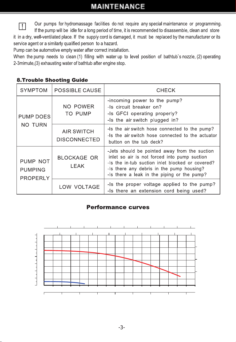
0
100 200 300 400
l/min
6
12
18
24
(m)
H
0
20
40
60
80 100 120
U.S.GPM
20 40
60
80
100
IMP.GPM
0
0
20
40
60
H
(ft)
0 6 12 18 24
m
3
/h
0
5
10
15
20
25
30
35
(PSi)
H
500 600
30 36
140 160
120
140
700
42
800
48
160 180
180 200 220
2
1
3
4
5
Brown
Blue
Black
Red
White
Capacitor
Capacitor
C
HERM
FAN
Red(High)
White(Common)
Black
(Low)
Red
(High)
White
(Common)
Green
Black ( Low )
Green
Centrifugal Switches
KW HP
800 17.5 220-240/60 2.2 3
244 1.8 220-240/60 0.22 0.3
M
odel Amps
75027
Qmax
(L/min)
Hmax
(m)
Volts/Hz
Power(P1)
10
1.2
76 194.9
424.3
77.1
79.6
209.2
88
164
210.9
212.5
217.8
∅
77.5
∅90
1
2
4/5
3
6
7
8
9
10
11
12
13
1
2
3
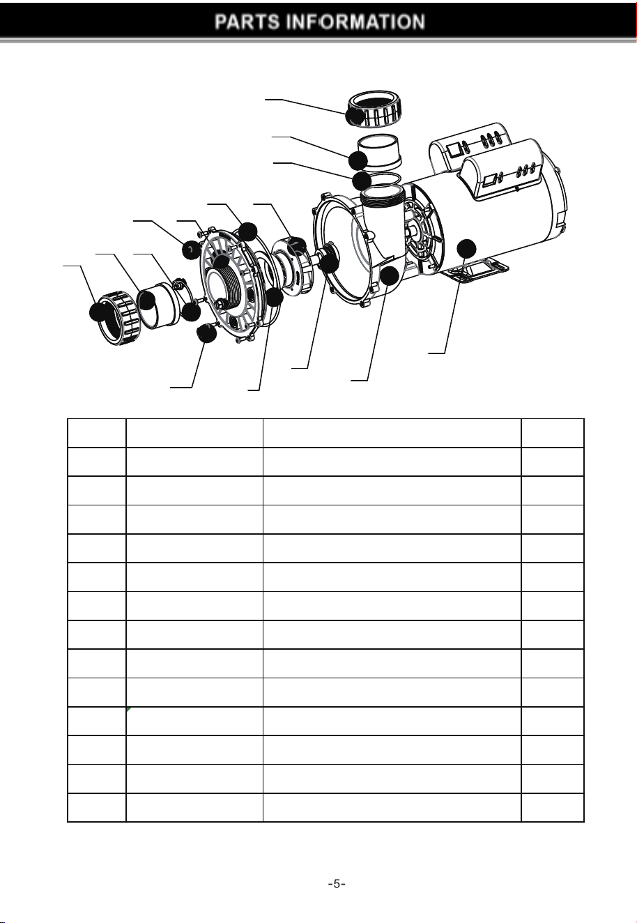
Ref.NO. PART NO. Description QTY
1 47018037001 Nut a d aptor 2
2 47018036001 A dap to r 2
3 5431031080 O-Ri ng 2
4 48860105080 drain p lug 3
5 5432002080 Gask et 3
6 5214027000 S cre w 8
7 47281007080 P ump c ove r 1
8 5431209080 O-ring 1
9 47281005080 diffus er 1
10 647281071000 Imp elle r 1
11 5028258000 Se a l ass embly 1
12 47281001080 P ump housing 1
13 5023428000
3HP motor
1