1
SWIMMING POOL HEAT PUMP
Manual
Owner's Manual

2
SWIMMING POOL HEAT PUMP
Manual
Contents
1. Introduction ............................................................................................................... 3
2.Heat Pump Technical Specifications .......................................................................... 4
3. Structure of Heat Pump ............................................................................................ 5
4. Installation Instructions .......................................................................................... 12
4.1 Location .......................................................................................................... 12
4.2 Water Piping ................................................................................................... 13
5. Electrical Connections ............................................................................................. 17
5.1 Electrical ......................................................................................................... 17
5.2 Bonding ........................................................................................................... 17
6. Wiring Diagram ........................................................................................................ 19
7. Service Analyzer Control ......................................................................................... 23
7.1 Panel description ............................................................................................ 23
7.2 Operation ........................................................................................................ 24
8. Service Analyzer Codes ........................................................................................... 25
9. Troubleshooting ...................................................................................................... 26
10. Initial Startup ......................................................................................................... 28
11. Requesting Assistance or Service ......................................................................... 29
12.Maintenance........................................................................................................... 29
13.Winterizing ............................................................................................................. 29
Please read carefully ................................................................................................ 30
Notes ........................................................................................................................... 31

3
SWIMMING POOL HEAT PUMP
Manual
1. Introduction
The pool heat pump is a self-contained unit designed specifically for pool heating.
Each component has been selected with care to achieve a high-quality product in an
effort to exceed all industry standards.
All pool heat pumps have an electronic board with service analyzer, a titanium heat
exchanger tube warranted for 10 years against corrosion and PVC plastic cabinet that
eliminates all maintenance for life. All components are of superior quality, which
presents you with an effective heat pump.
Compared to other types of pool heaters, such as gas or oil-fired, the pool heat pump
has a lower heating capacity on a BTU/h basis. Therefore, it needs to operate for a
longer time to accomplish the desired results. Occasionally, it may be necessary to
run the heat pump for up to 24 hours per day. However, this should not be of
concern to the owner because the heater is designed to operate continuously.
What’s more, despite continuous operation, it will still heat the pool far more
economically than other types of heaters.
As with all pool heaters, you are advised to use a pool cover at night and when the
pool is not in use. The pool cover should be used if night temperatures are 15°F less
than desired pool temperature. This will keep evaporation, the greatest source of
heat loss, to a minimum, thus greatly reducing the overall pool heating costs. During
warmer weather, the pool cover may not be required.
4
SWIMMING POOL HEAT PUMP
Manual
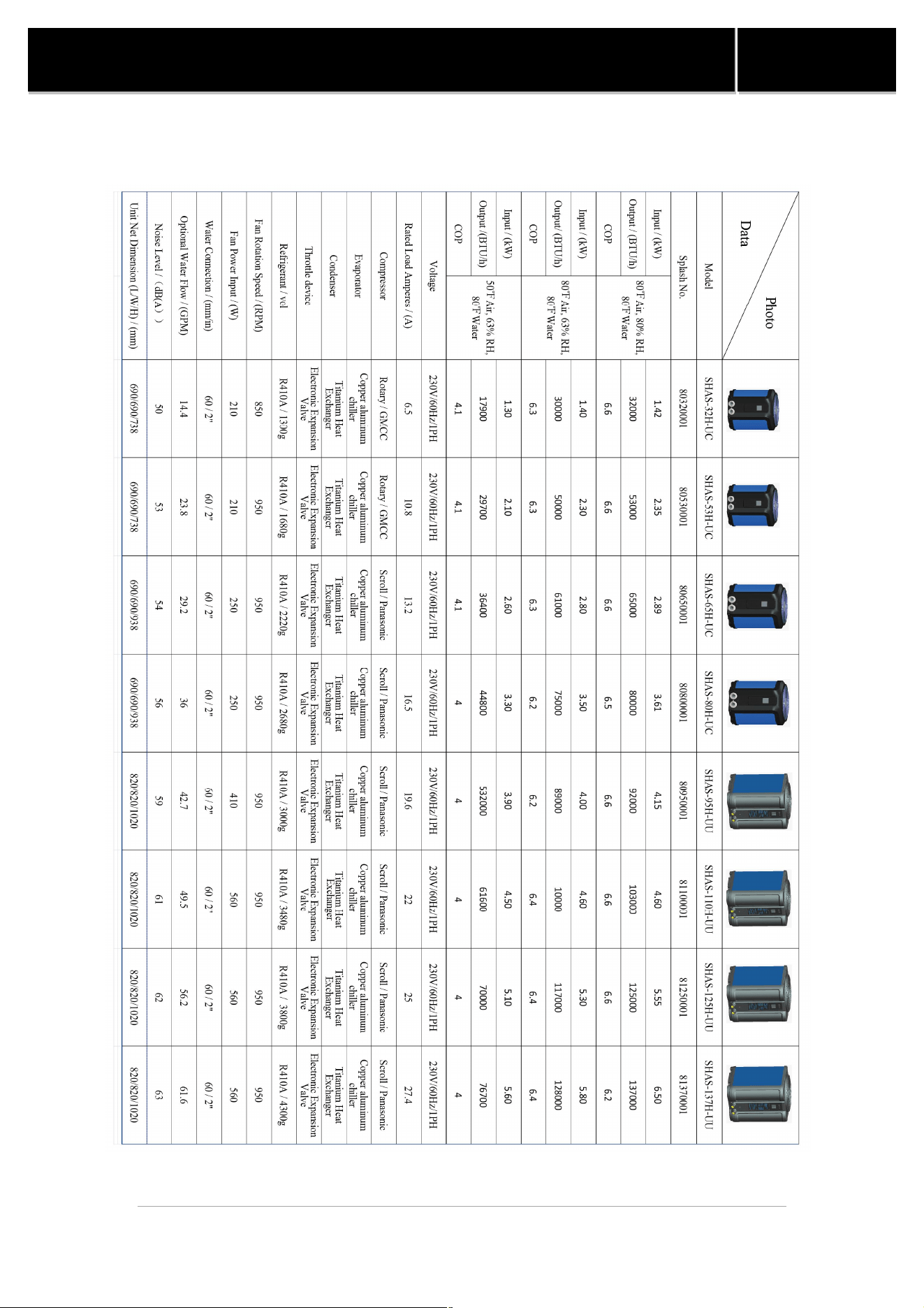
2.Heat Pump Technical Specifications
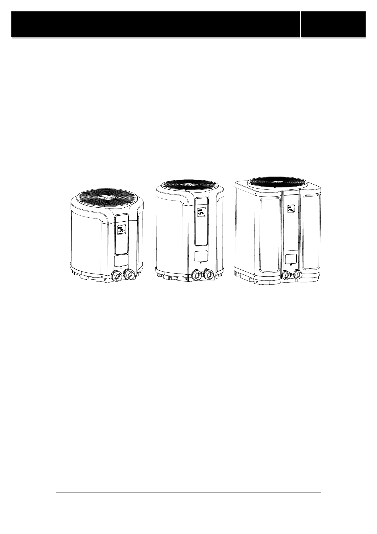
SWIMMING POOL HEAT PUMP
3. Structure of Heat
P
Figure 1. SHAS-
32/53/65/80H
5
SWIMMING POOL HEAT PUMP
P
ump
32/53/65/80H
-
UC Heat Pump Exploded View
Manual
UC Heat Pump Exploded View
SWIMMING POOL HEAT PUMP
Figure 2. SHAS-95/110/
12
6
SWIMMING POOL HEAT PUMP
12
5/137H-
UC Heat Pump Exploded View
Manual
UC Heat Pump Exploded View
7
SWIMMING POOL HEAT PUMP
Manual
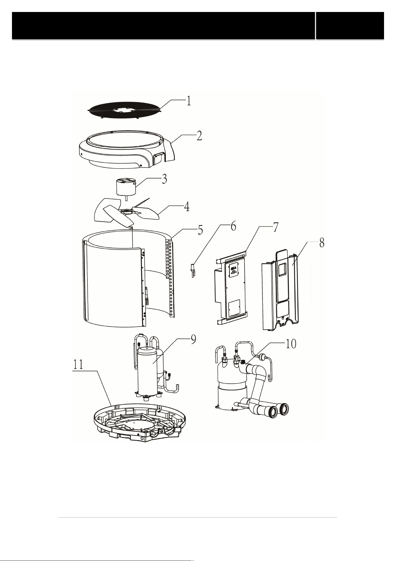
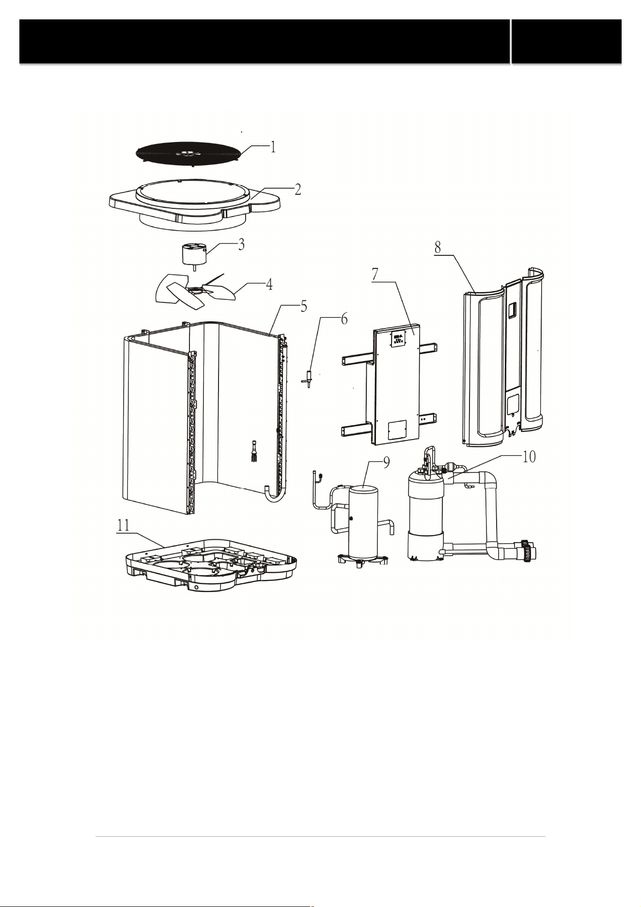
As the picture shows, the components of the heat pump is listed in the form.
Table1. Parts of Heat Pump
NO. Parts of Heat Pump
1
Fan Guard
2
Roof Cover
3
Fan Motor
4
Fan Blade
5
Cooper Aluminum Chiller (Evaporator)
6
Electrical Expansion Valve
7
Electrical Box
8
Front-Panel
9
Compressor
10
Titanium Heat Exchanger (Condenser)
11
Chassis
SWIMMING POOL HEAT PUMP
²
As the picture shows, the titanium exchanger
refrigerant and offers
high resistance to
excellent heat exchange.
Table2
. Parts of
No. Parts
of heat exchanger
1
Copper Connection Pipe
2
Copper Filter Pipe
3 Lock Ring
4
Plastic Screw Nut
5 Seal Ring
6
Water Outlet
7
Drain Outlet
Figure 3.
Titanium Heat Exc
8
SWIMMING POOL HEAT PUMP
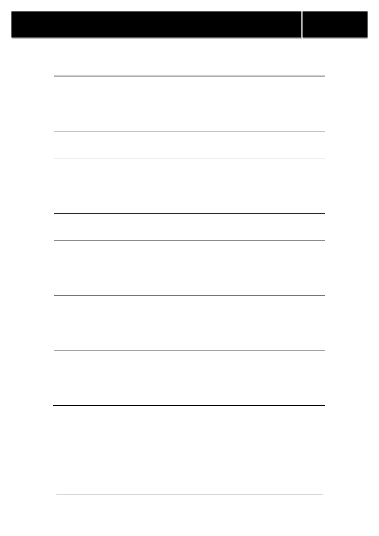
As the picture shows, the titanium exchanger
exchanges heat with the
high resistance to
chemical products while
ensuring an
. Parts of
Titanium Heat Exchanger
of heat exchanger
No. Parts
of heat exchanger
Copper Connection Pipe
8 Water Inlet
Copper Filter Pipe
9 200mm Top Cap
10
200mm PVC Pipe
Plastic Screw Nut
11 200mm
Bottom Cap
12 Metal Sleeve
Water Outlet
13 Titanium Pipe
Drain Outlet
14
Intermedium Tube
Titanium Heat Exc
hanger Exploded View
Manual
exchanges heat with the
ensuring an
of heat exchanger
200mm PVC Pipe
Bottom Cap
Intermedium Tube
SWIMMING POOL HEAT PUMP
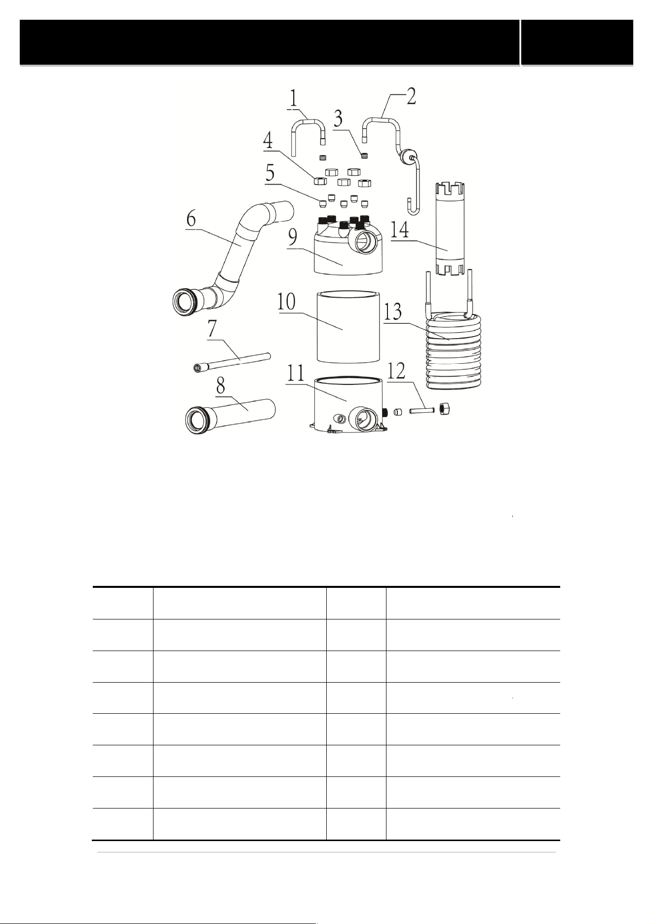
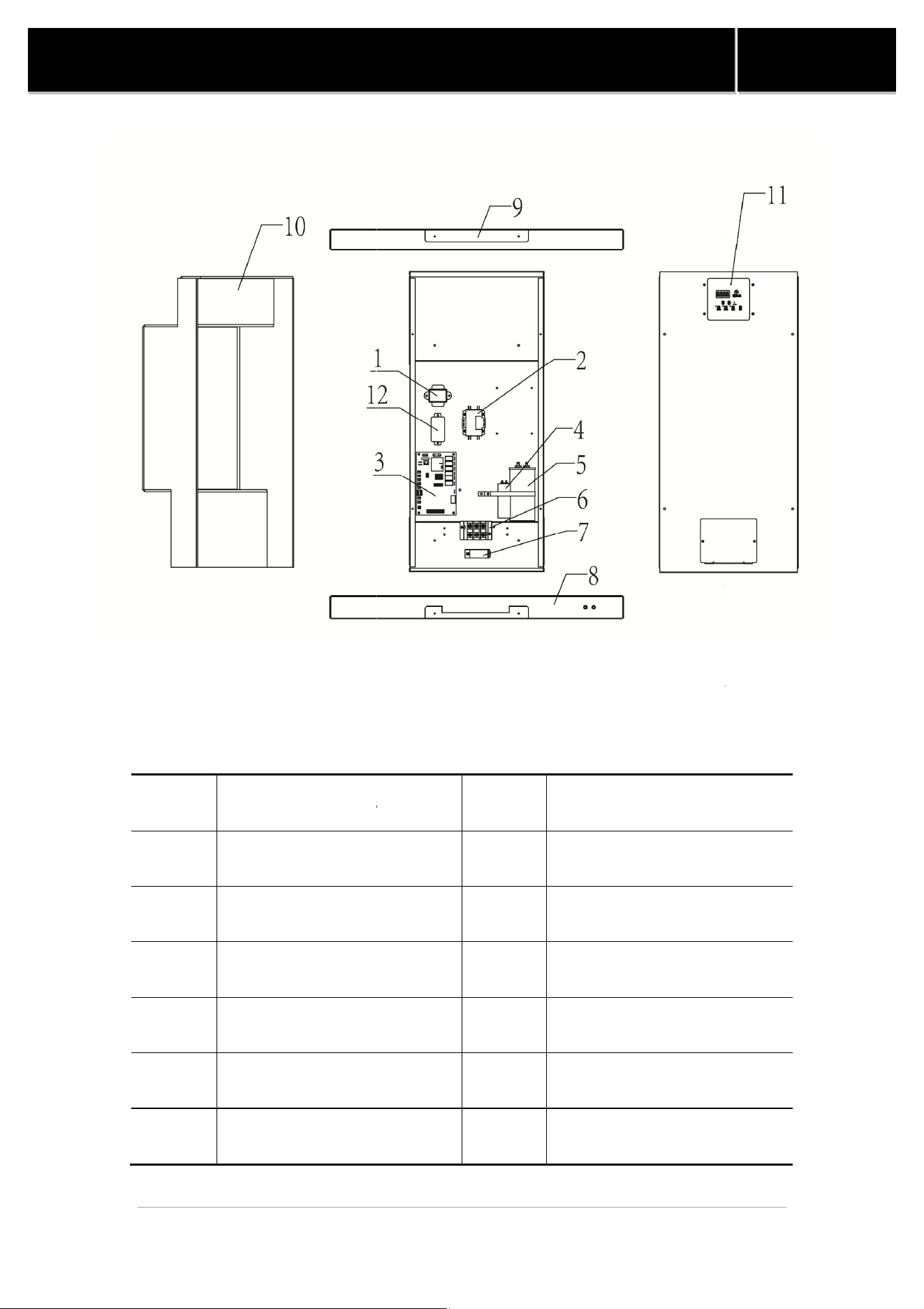
Table3. Parts of SHAS
No. Parts of
Electrical Box
1
Transformer
2 Relay (32H) or
Contactor
3 Main
Control Board
4
Fan Capacitor
5
Compressor Capacitor
6
Terminal Strip
Figure 4. SHAS-
32/53/65/80H
9
SWIMMING POOL HEAT PUMP
Table3. Parts of SHAS
-32/53/65/80H-UC Electrical Box
Electrical Box
No. Parts of
Electrical Box
Transformer
7 Wire Clamp
Contactor
( 53H)
8 Under
Fixed Plate
Control Board
9
Upper Fixed Plate
Fan Capacitor
10 Sponge Layer
Compressor Capacitor
11
Wire Controller Panel
Terminal Strip
12
32/53/65/80H
-UC Electrical Box
Exploded View
Manual
Electrical Box
Fixed Plate
Upper Fixed Plate
Wire Controller Panel
Exploded View
SWIMMING POOL HEAT PUMP
Table4. Parts of SHAS
No. Parts of
Electrical Box
1
Transformer
2 Contactor
3
Main Control Board
4
Fan Capacitor
5
Compressor Capacitor
6
Terminal Strip
Figure 5. SHAS-
95H
10
SWIMMING POOL HEAT PUMP
Table4. Parts of SHAS
-95H-UU Electrical Box
Electrical Box
No. Parts of
Electrical Box
Transformer
7 Wire Clamp
8
Under Fixed Plate
Main Control Board
9
Upper Fixed Plate
Fan Capacitor
10 Sponge Layer
Compressor Capacitor
11
Wire Controller Panel
Terminal Strip
12 Relay
95H
-UU Electrical Box
Exploded View
Manual
Electrical Box
Under Fixed Plate
Upper Fixed Plate
Wire Controller Panel
Exploded View
SWIMMING POOL HEAT PUMP
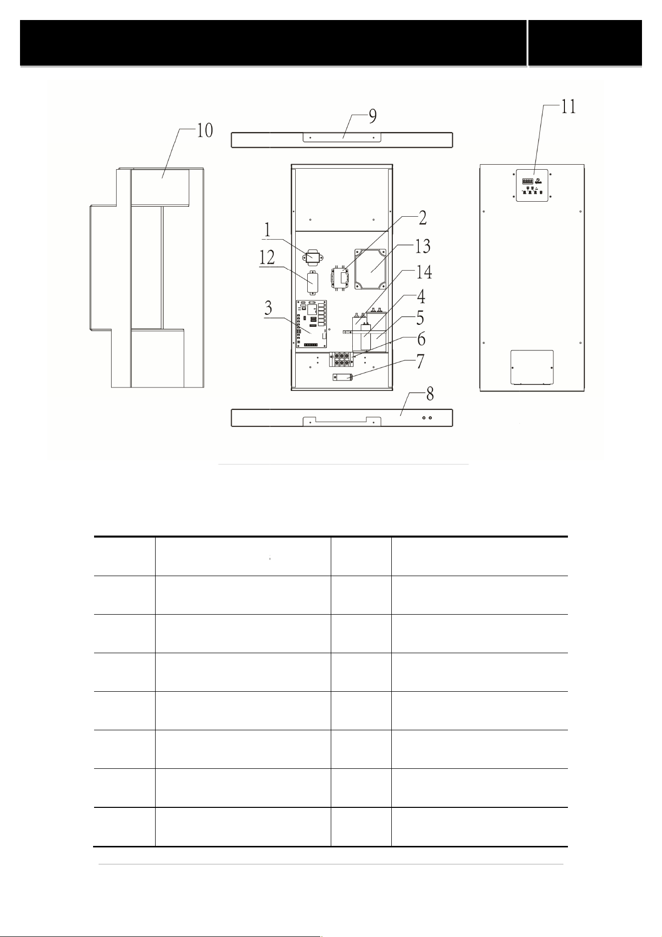
Table5. Parts of SHAS
No. Parts of
Electrical Box
1
Transformer
2 Contactor
3
Main Control Board
4
Fan Capacitor
5
Compressor Capacitor
6
Terminal Strip
7
Wire Clamp
Figure 5. SHAS-
110/125/137H
11
SWIMMING POOL HEAT PUMP
Table5. Parts of SHAS
-110/125/137H-UU Electrical Box
Electrical Box
No. Parts of
Electrical Box
Transformer
8
Under Fixed Plate
9
Upper Fixed Plate
Main Control Board
10 Sponge Layer
Fan Capacitor
11
Wire Controller Panel
Compressor Capacitor
12 Relay
Terminal Strip
13 Soft Starter
Wire Clamp
14
Motor Start Capacitor
110/125/137H
-UU Electrical Box
Exploded View
Manual
Electrical Box
Under Fixed Plate
Upper Fixed Plate
Wire Controller Panel
Motor Start Capacitor
Exploded View
12
SWIMMING POOL HEAT PUMP
Manual
4. Installation Instructions
4.1 Location
The placement of the pool heater is very important in keeping installation costs to a
minimum while providing for maximum efficiency of operation, as well as allowing
adequate access for service and maintenance.
The pool heat pump is designed for outdoor installation and should not be installed
in a fully enclosed area, such as a shed, garage, etc. Recirculation of cold discharged
air back into the evaporator coil will greatly reduce unit heating capacity and
efficiency.
The unit should be located as close as practical to the existing pool pump and filter to
minimize water piping. However, do not forget to provide a clearance(Table 6) at the
very least all around your heat pump. The use of 90 degree bends and short radius
elbows in the water piping should be kept to a minimum.
Mount the unit on a sturdy base, preferably a concrete slab or a set of blocks. The
base should be completely isolated from the building foundation wall to prevent the
possibility of sound or vibration transmission into the building. The size of the base
should not be less than the size of the heat pump.
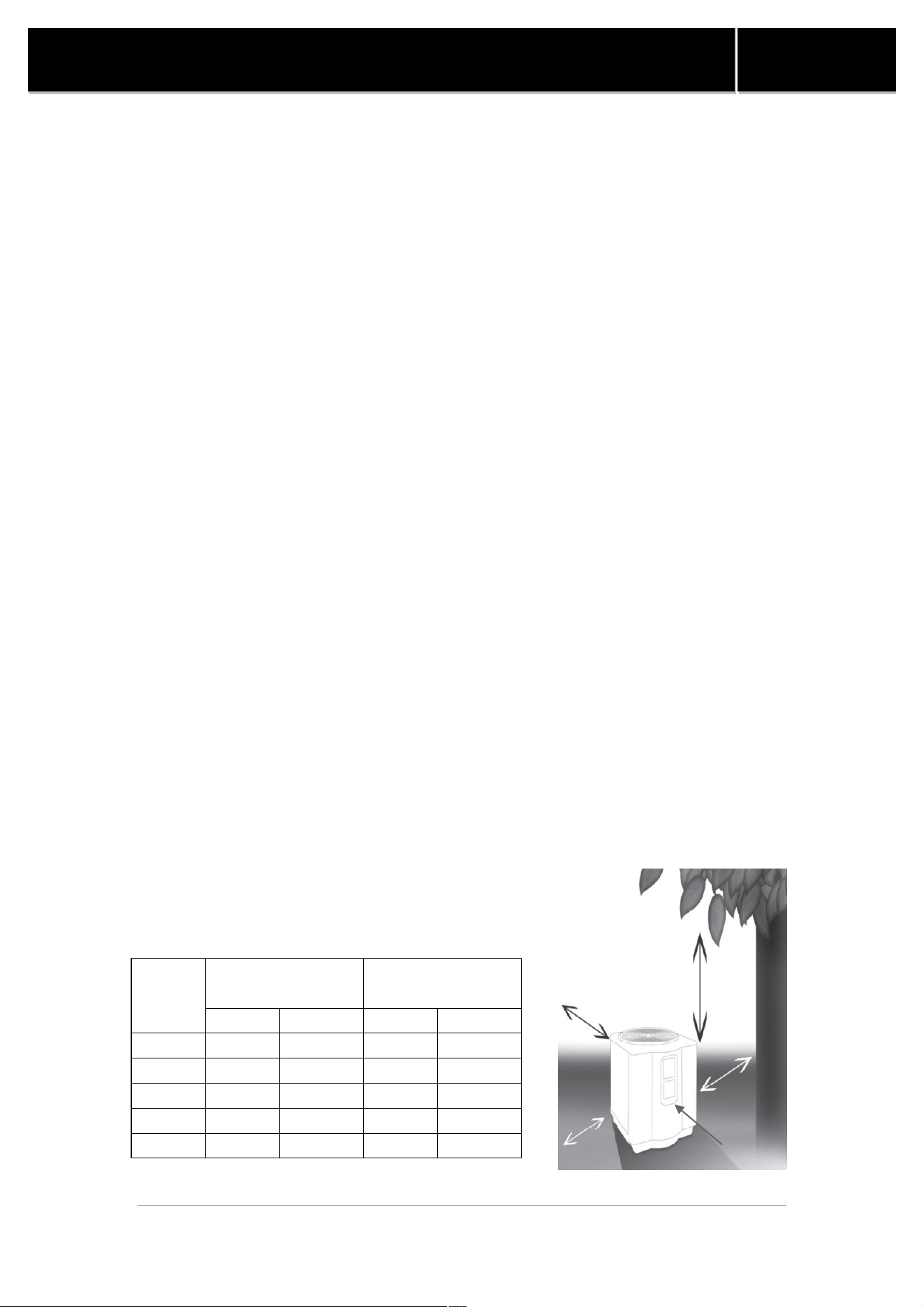
² Important
² Air is pulled through the evaporator coil and discharged through the top grille.
A minimum clearance of 60 inches should be allowed above the unit for
unrestricted air discharge. The unit must not be installed under a porch. Any
side of the unit should be located at least 24 inches from a wall or from any
other obstruction for unrestricted air intake and service access.
Side of
Heat
Pump
Minimum Clearances for
Operation
Recommended Clearances
for Serviceability
Inches
Centimeters
Inches
Centimeters
Front
24 60 36 90
Rear
12 30 24 60
Left
12 30 24 60
Right
12 30 24 60
Top
60 150 60 150
Table 6. Heat Pump Clearances
Rear
Left
Top
Right
Front

13
SWIMMING POOL HEAT PUMP
Manual
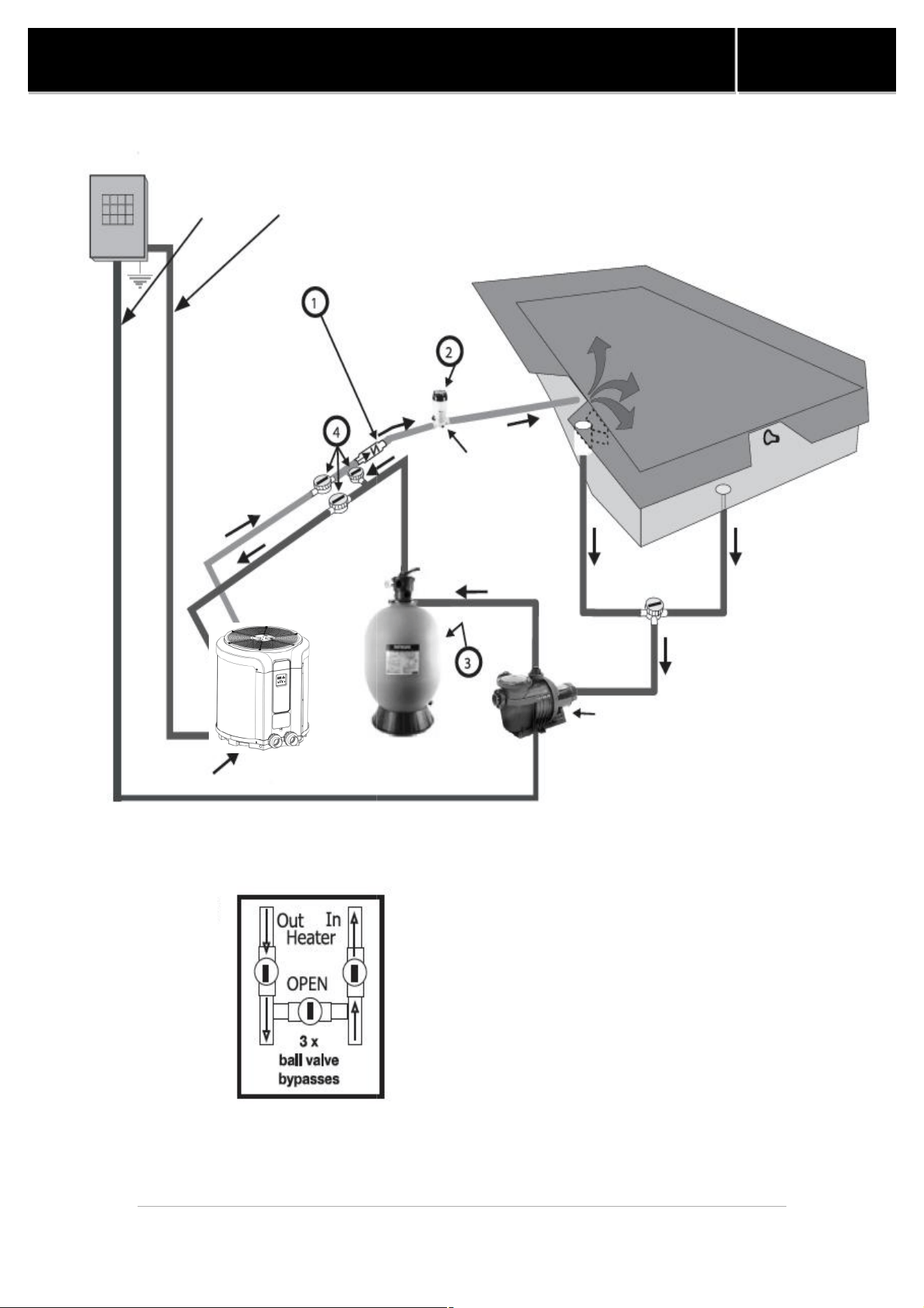
4.2 Water Piping
² Single Unit Installation
Figure 6 illustrates the standard plumbing layout with a single heat pump unit.
Following the diagram from right to left, the plumbing sequence is as follows: Pool >
Pool Pump > Filter > Heat Pump > Check Valve > Chemical Feeder > Pool. Note For
normal installations, do not install a shutoff valve or any kind of variable restriction in
the water piping between the heat pump outlet and the pool/spa.
Filtered water is plumbed to the inlet, located on the right side of the heat pump
front panel. Heated water flows through the outlet, located on the left side of the
heat pump front. Two inch unions are provided.
Automated chlorine distribution systems, if used, must be placed downstream of
the heater to minimize harm to the pool equipment. Use rigid PVC piping if possible.
All joints should be glued with PVC glue. When the piping installation is complete,
operate the pool pump and check the system for leaks. Then, check the filter
pressure gauge to verify that there isn’t any indication of excessive pump head
pressure. You can also make the connections using high-pressure flexible hose, but
make sure the hose can withstand high pressure. The installation of a heat pump
bypass is not necessary unless the water flow exceeds 75 GPM.
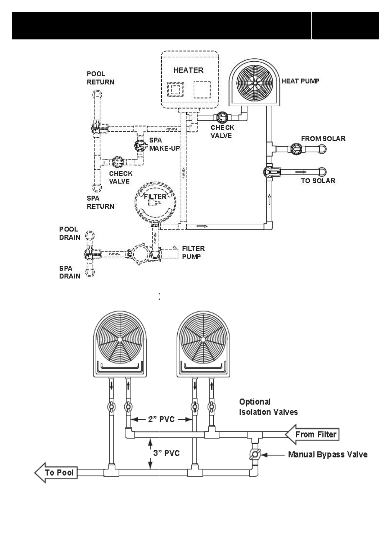
² Multiple Unit Installation
Heat Pump and Heater Combination
In certain regions of the country it may be more economical to run a heat pump
during the warmer months and a gas heater during the cooler months. In some
situations it may be desirable to run the heat pump in the “Chiller” mode during
the hottest portion of the year and a heater during the cooler months. The heat
pump may be plumbed with a gas or electric heater or any combination of heat
sources including solar. All heat sources must be plumbed in series to work correctly
and efficiently.
Figure 7 illustrates a recommended plumbing layout for a heat pump / heater /
solar combination heating system for a pool / spa combination. Your system may not
contain all of these components, but the basic plumbing will apply by eliminating the
component in the illustration that is not a part of your system.
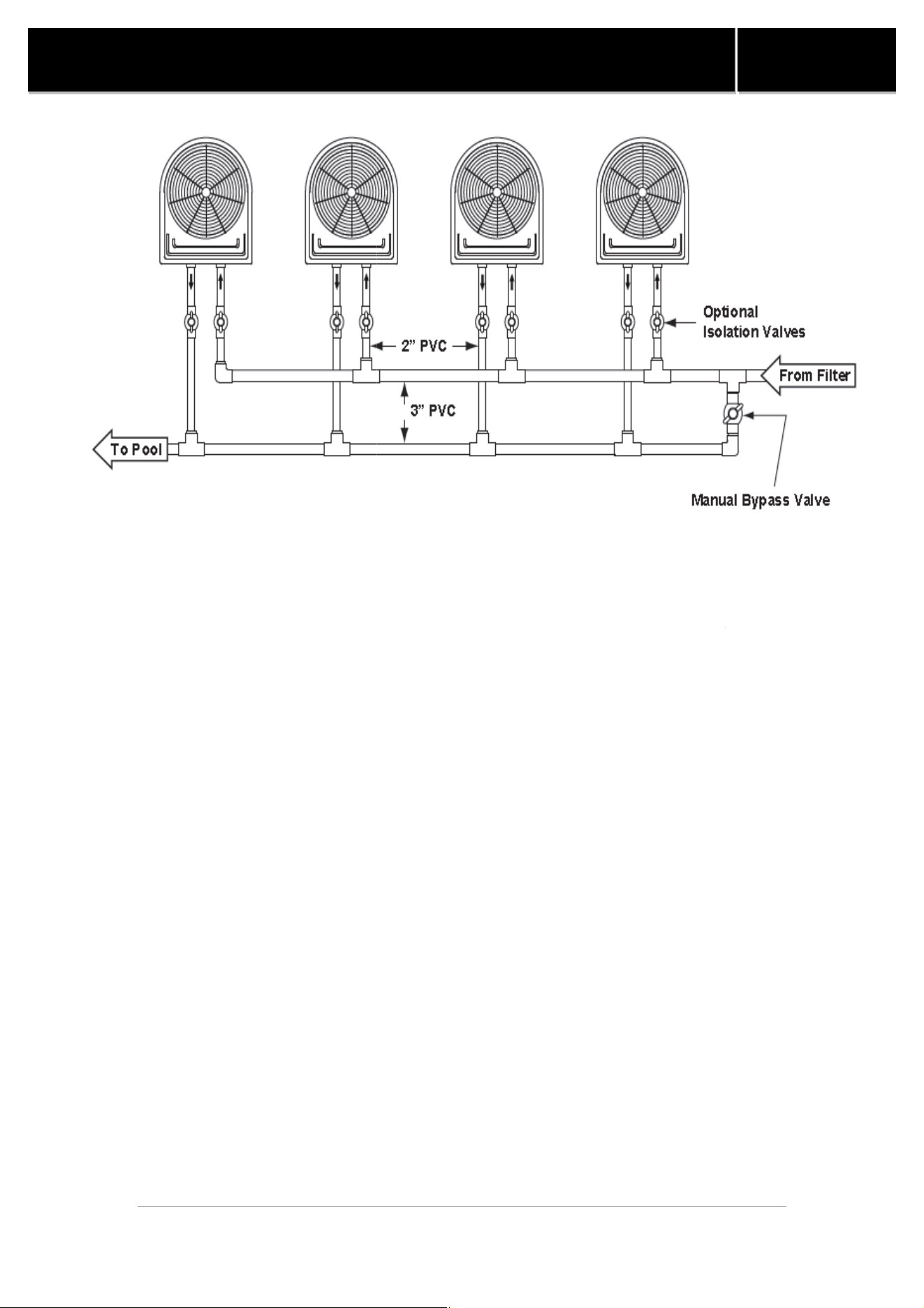
Multiple Heat Pump Connections
All plumbing on multiple heat pump installations must be done in parallel (see
Figures 8 and 9). An equal flow of water to each heat pump is important for optimum
operation.
Note: It may be necessary to adjust water pressure switch if a unit is installed
below the water level. See Section 5.6 for details on when and how to adjust the
pressure switch. Each heat pump allows a maximum flow rate of 70 gpm (265 lpm)
and requires a minimum of 20 gpm (76 lpm).
SWIMMING POOL HEAT PUMP
Figure 6.
Standard Plumbing Layout
Heat Pump
Check Valve
Bypass Valves
Wire Conduits
Power Supply and Grounding
14
SWIMMING POOL HEAT PUMP
Standard Plumbing Layout
Chemical Feeder
Pool Pump
Filter
Power Supply and Grounding
Manual
SWIMMING POOL HEAT PUMP
Figure 8.
Two(2) Heat Pump Plumbing Layout
Figure 7. P
lumbing For Heating System Combinations
15
SWIMMING POOL HEAT PUMP
Two(2) Heat Pump Plumbing Layout
lumbing For Heating System Combinations
Manual
Two(2) Heat Pump Plumbing Layout
lumbing For Heating System Combinations
SWIMMING POOL HEAT PUMP
² Important
Certain installations have valves which isolate the heat pump from the
If the heat exchanger
is deprived of water circulation for several days, high chlorine
gas could cause excessive corrosion. If the disconnect
that the pool water is allowed to circulate through the unit, or is
Figure 9.
Four(4) Heat Pump Plumbing Layout
16
SWIMMING POOL HEAT PUMP
Certain installations have valves which isolate the heat pump from the
water circuit.
is deprived of water circulation for several days, high chlorine
gas could cause excessive corrosion. If the disconnect
switch is turned off, be sure
that the pool water is allowed to circulate through the unit, or is
drained out of it.
Four(4) Heat Pump Plumbing Layout
Manual
water circuit.
is deprived of water circulation for several days, high chlorine
switch is turned off, be sure
drained out of it.
Four(4) Heat Pump Plumbing Layout

17
SWIMMING POOL HEAT PUMP
Manual
5. Electrical Connections
5.1 Electrical
The wiring of your pool heat pump should be performed by a qualified electrician
in accordance with local requirements. A properly-sized breaker and copper wire
must be used. Check the heat pump data label for required maximum breaker size
² Important
The unit must always be powered off before opening the access panel.
5.2 Bonding
Because all metals have different electrical potentials, all metal and electrical
components of the pool system must be bonded together. This includes the metal
framework of the pool, the light, the pump, the filter (if made out of metal), the
heater, any automatic chlorine generator, and any other metal or electrical
equipment. On some older pools, this substructure bond wire may not exist. In these
cases, a 6 to 8 foot solid copper rod must be driven into the ground near the
equipment. All electric and metal components must then be bonded to each other,
and then to the copper rod.
² Important
² Check valve must be installed between the heater and any automatic chlorine
distribution system (if used);
² Any kind of automatic chlorine distribution system must be installed after or
downstream of the heat pump;
² The filter must be placed before or upstream from the heat pump;
² A bypass and shut-off should be installed on all systems for ease of service,
maintenance and to balance the water flow. Bypasses must be installed on any
system with over a 3/4 HP pool pump.
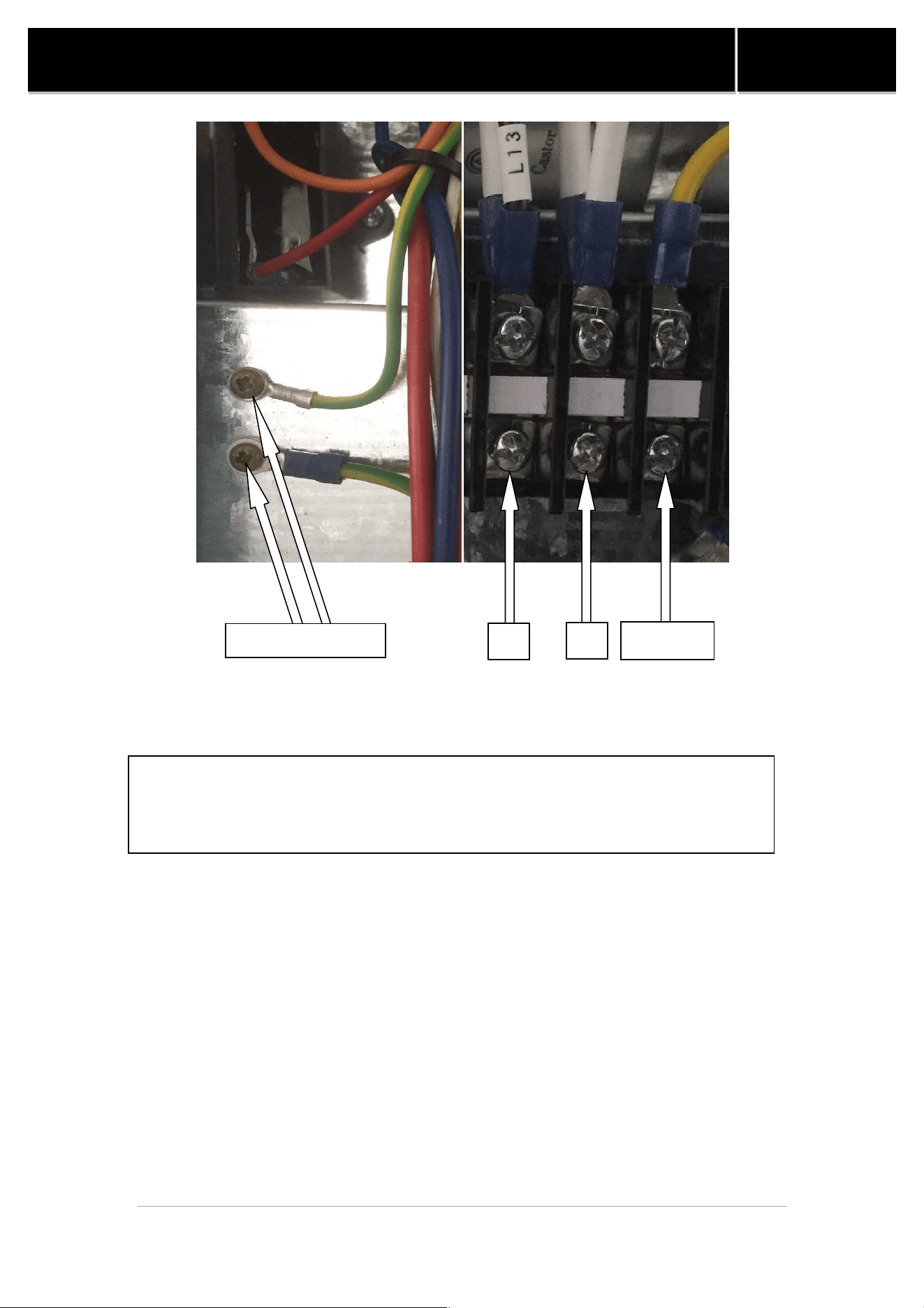
The installation of the pool heater should be performed by a certified electrician. To
connect the electricity, you must unscrew the two screws under the front panel, then
slide the electric cable through the knock out located on the left or the right side of
the base, and then insert it in the control box.
18
SWIMMING POOL HEAT PUMP
Manual
Power requirements : 230VAC ,1PH, 60Hz
Look at the nameplate located on the heat pump to know the required amperage
Please refer to your local electrical code for additional wiring requirements
Ground
L1
L2
G
Figure 10. Electrical Supply of Electrical Box
SWIMMING POOL HEAT PUMP
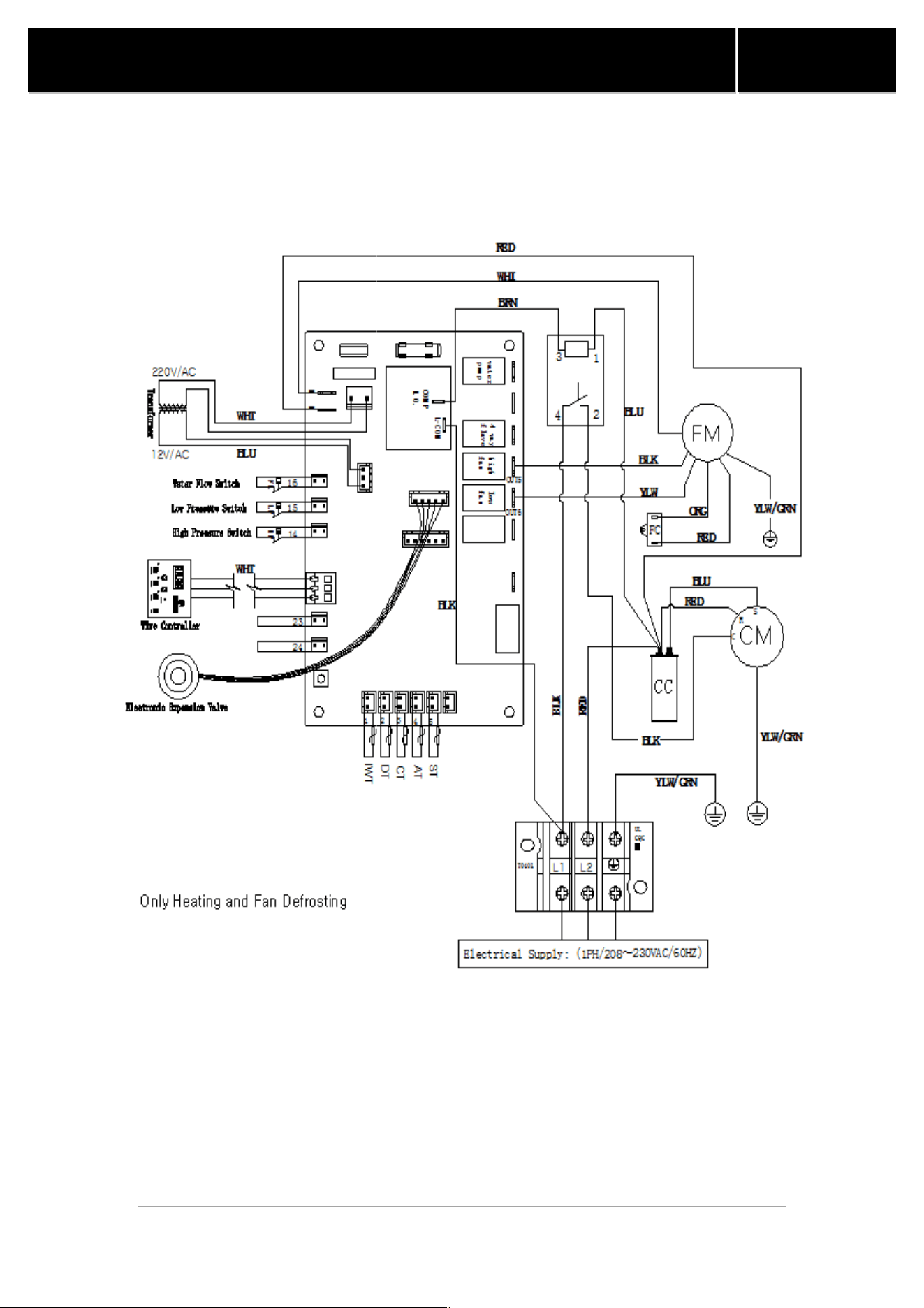
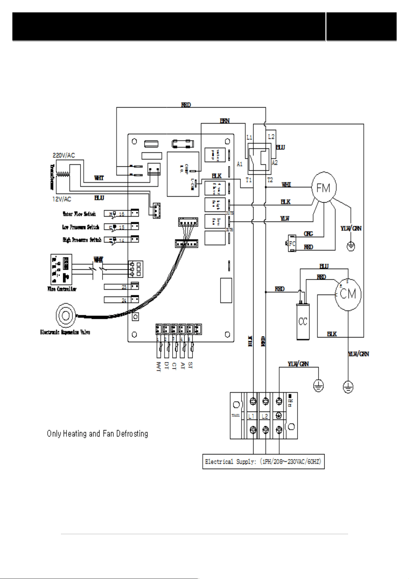
6. Wiring Diagram
Figure 11.
SHAS
19
SWIMMING POOL HEAT PUMP
SHAS
-32H-UC Wiring Diagram
Manual
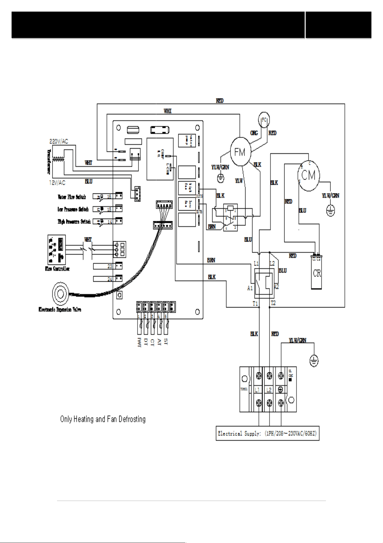
SWIMMING POOL HEAT PUMP
Figure 12. SHAS-
53/65/80H
20
SWIMMING POOL HEAT PUMP
53/65/80H
-UC Wiring Diagram
Manual
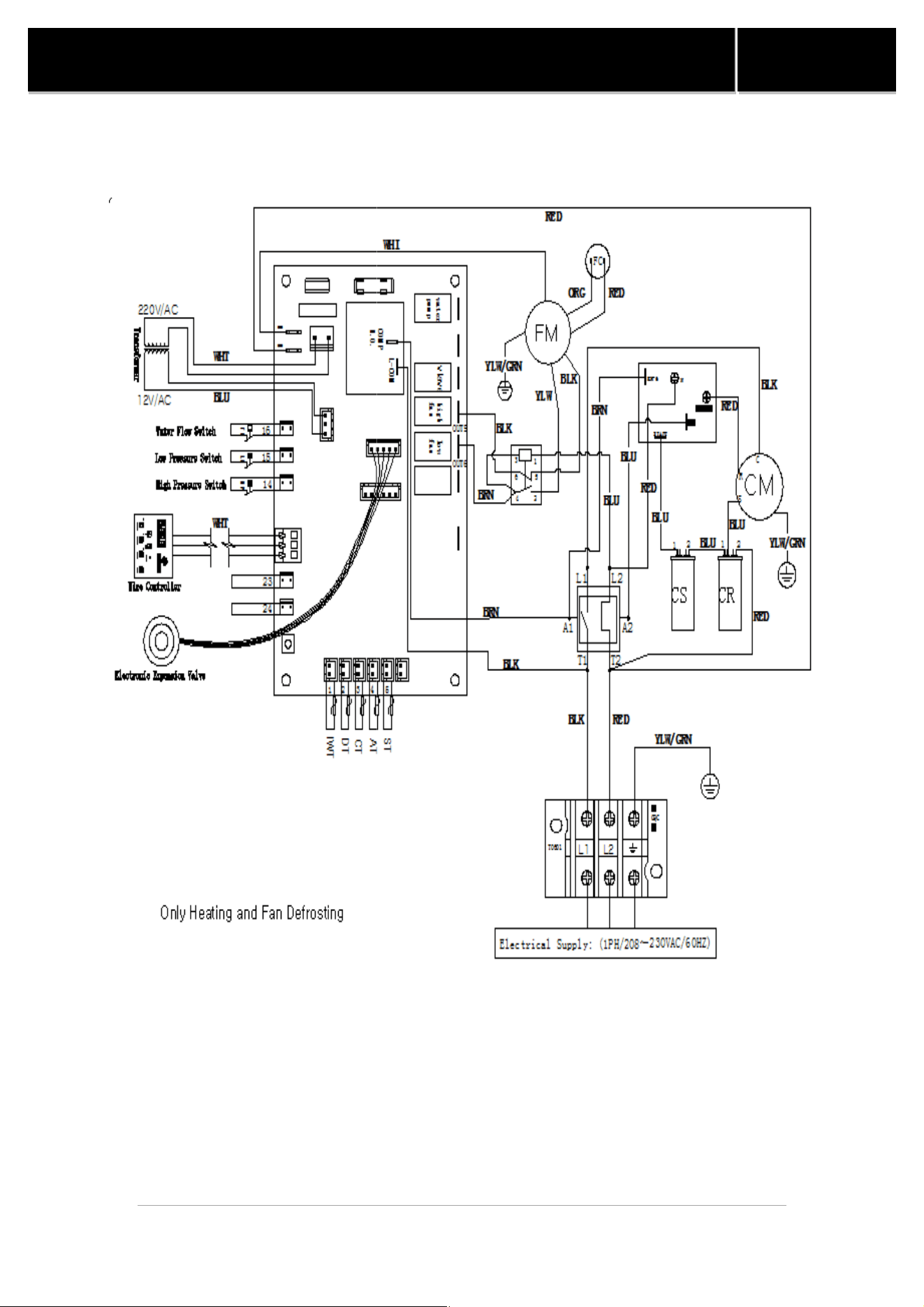
SWIMMING POOL HEAT PUMP
Figure 13.
SHAS
21
SWIMMING POOL HEAT PUMP
SHAS
-95H-UU Wiring Diagram
Manual
SWIMMING POOL HEAT PUMP
Figure 14. SHAS-
110/125/137H
22
SWIMMING POOL HEAT PUMP
110/125/137H
-UU
Wiring Diagram
Manual
Wiring Diagram
SWIMMING POOL HEAT PUMP
7
. Service Analyzer Control
The control panel is factory set to display the te
can also be displayed as
degree centigrade
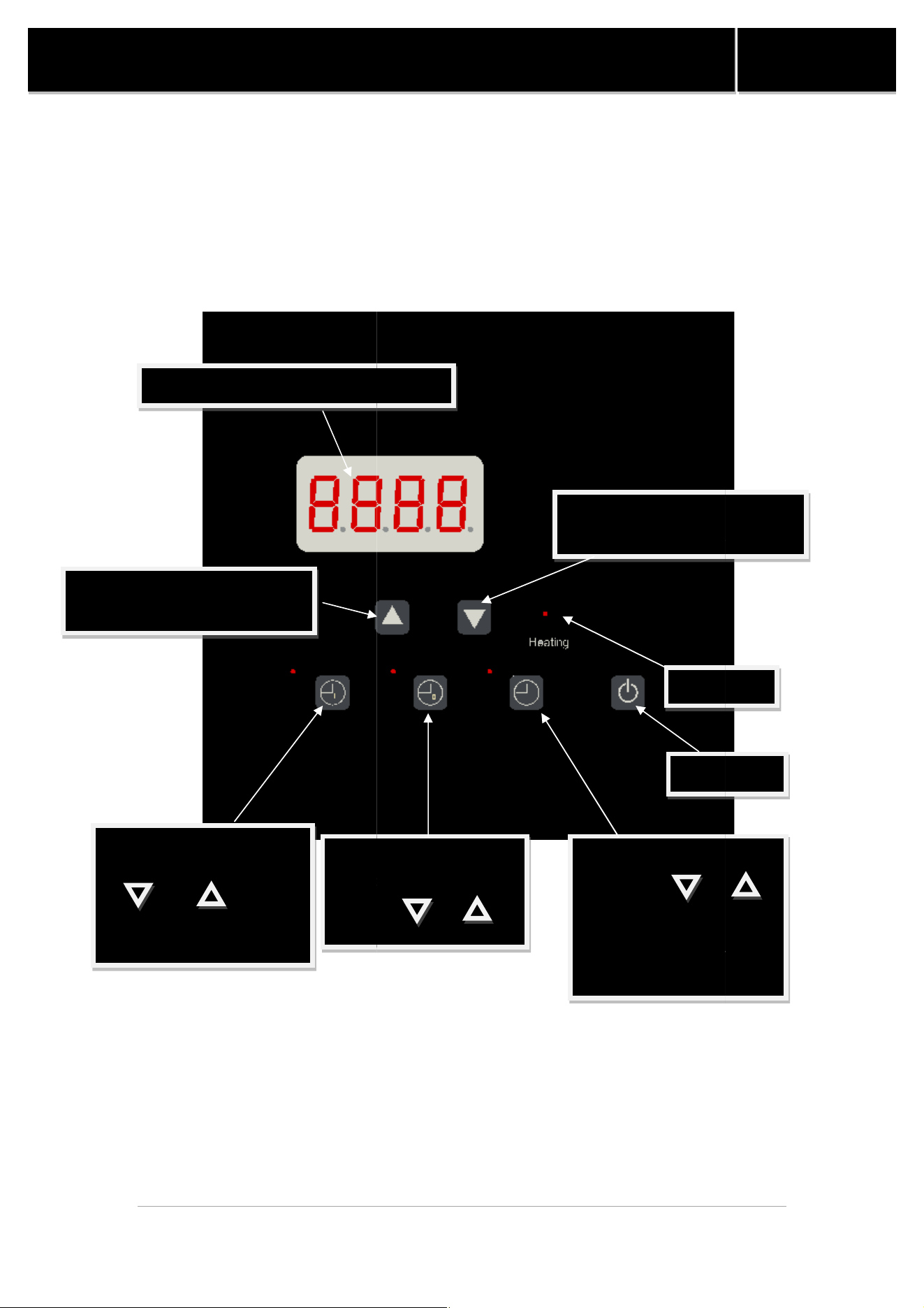
7.1 Panel Description
Temperature and parameter display screen
To raise the desired temperature
or to change parameters
Timer which sets and
adjusts the shutdown time
with the " and "
button.
Timer which sets and adjusts
the running time with the
" and " button.
Long press it for 10s to
change "℉" or "℃" display.
Figure
15
23
SWIMMING POOL HEAT PUMP
. Service Analyzer Control
The control panel is factory set to display the te
mperature in Fahrenheit degrees
degree centigrade
.
Temperature and parameter display screen
To lower the desired temperature
or to change
parameters
Switch on/o
Clock setting and adjusting
with the " and "
button. Long press the key
for 10s to check the
temperature parameters by
related temperature sensor
Timer which sets and
adjusts the shutdown time
with the " and "
button.
Display light
15
. Panel Description
Manual
mperature in Fahrenheit degrees
, it
To lower the desired temperature
parameters
Switch on/o
ff
Clock setting and adjusting
with the " and "
button. Long press the key
for 10s to check the
temperature parameters by
related temperature sensor
Display light
SWIMMING POOL HEAT PUMP
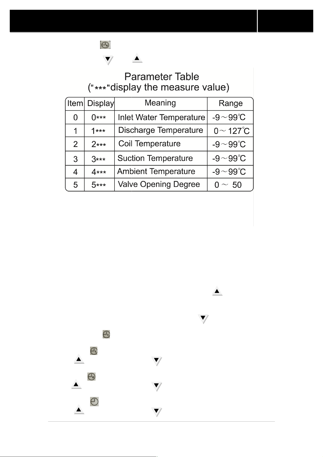
Long press the "
" button for 10s to examine the running parameter, change
the item with the "
and " button to check the measure value.
²
For Example: Display "026.5", it means the inlet water temperature is 26.5
Display"146.5", it means discharge temperature is 46.5
7.2 Operation
²
To increase the temperature
Proceed as explained above using the up arrow
temperature setting 0.5 degree at a time.
² To lower the temperature
Proceed as explained above using the down arrow
²
To display the temperature in
Long press the
key for 10s to switch
² To set running time
Press the
key to enter setting mode
key
and the down arrow key
² To set shutdown time
Press the
key to enter
key and the
down arrow key
² To set the clock
Press the key to enter setting mode, adjusting the value with the up arrow
key and the down arrow key
Figure
24
SWIMMING POOL HEAT PUMP
" button for 10s to examine the running parameter, change
and " button to check the measure value.
For Example: Display "026.5", it means the inlet water temperature is 26.5
Display"146.5", it means discharge temperature is 46.5
℃
To increase the temperature
Proceed as explained above using the up arrow
to increase the
temperature setting 0.5 degree at a time.
Proceed as explained above using the down arrow
.
To display the temperature in
℉
or in
℃
key for 10s to switch
℉ or ℃
key to enter setting mode
,
adjusting the value with the up arrow
and the down arrow key
.
key to enter
setting mode, adjusting the value with the up arrow
down arrow key
.
Press the key to enter setting mode, adjusting the value with the up arrow
key and the down arrow key
.
Figure
16. Parameter Table
Manual
" button for 10s to examine the running parameter, change
For Example: Display "026.5", it means the inlet water temperature is 26.5
℃;
to increase the
adjusting the value with the up arrow
setting mode, adjusting the value with the up arrow
Press the key to enter setting mode, adjusting the value with the up arrow
25
SWIMMING POOL HEAT PUMP
Manual
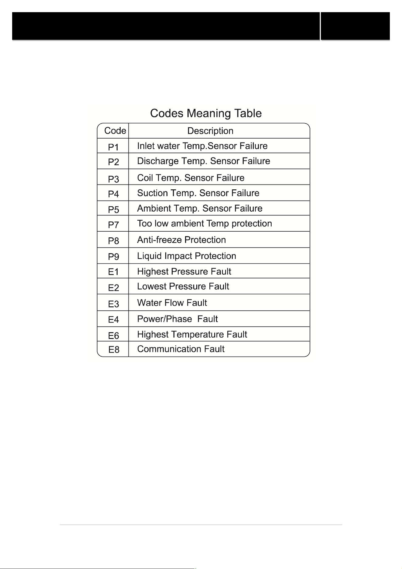
8. Service Analyzer Codes
Most problems will be detected by the service analyzer and a code will be
displayed on the digital display of your heater. The meaning of Display Codes are
as follows:
Figure 17. Codes Meaning Table
26
SWIMMING POOL HEAT PUMP
Manual
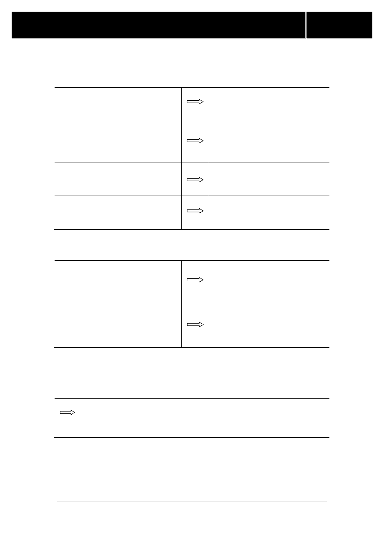
9. Troubleshooting
The pool heater is not running
Heat pump control set to OFF Turn the heat pump on
Desired water temperature is reached
Unit will automatically restart when
the water temperature goes below
the set point
Main breaker is tripped
Reset main breaker and restart heat
pump
Filter is dirty, restricting the water
flow.
Backwash and clean filter
The fan is running, but the compressor is not
The heat pump is in protection mode
In this case, there may be a delay
before restarting.
The unit is on defrost cycle
The compressor will automatically
start again a few minutes until it
has stopped three times
continuously.
There is no display and the fan is not running but the compressor is
running
Ask your electrician to verify your heat pump's power supply by checking over
the L1/L2/L3 connections in the unit's service box
27
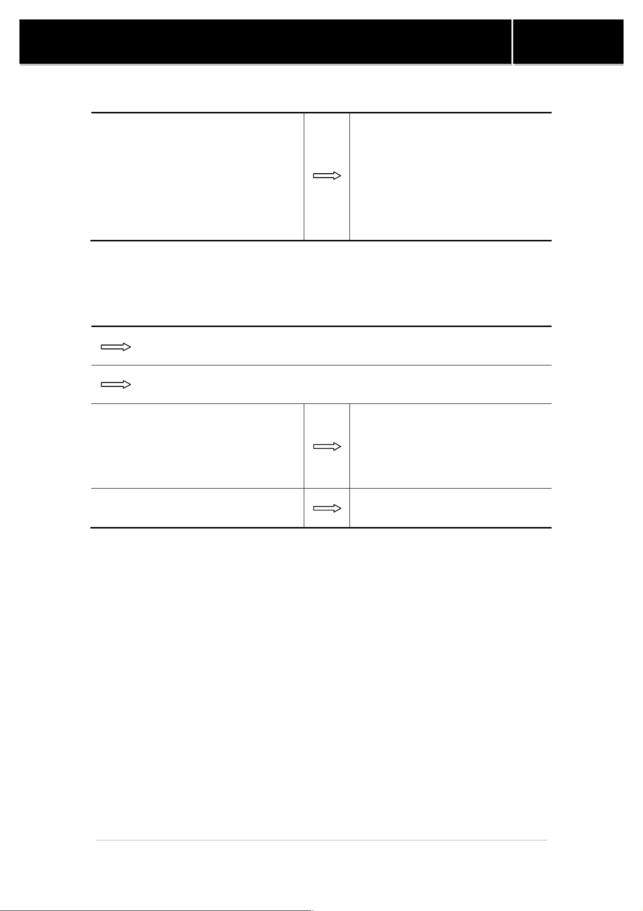
SWIMMING POOL HEAT PUMP
Manual
There is water around the unit
While your pool heater is in the
heating mode, a large quantity of
warm and humid air passes over the
evaporator and causes condensation.
It is normal to see condensation
dripping under the heater.
To check if the water really is a leak,
you must stop the heater and leave
the pool pump running for over 5
hours. If water is still coming out of
your heater after this period, then
call your dealer for service.
The heater is running but desired water temperature cannot be
reached.
Heat loss is too much for heater; cover your pool as often as you can.
Evaporator restricted due to improper location
Evaporator is dirty
Clean it by running tap water over
the coil without additional nozzel
attachment. Do not use pressurized
water as it can damage the coil and
void warrantly.
Restricted water flow Adjust water flow
² Important
If your pool heater does not operate for reasons other than those mentioned
above, please contact Consumer Assistance Center to obtain the proper
authorization for the warranty to apply.

28
SWIMMING POOL HEAT PUMP
Manual
10. Initial Startup
² Before starting the pool heater for the first time, it is important to verify that the
breaker is in the ON position.
² Also make sure that the water circulates freely and that the pool pump is
activated.
² Then, you will need to set the water temperature you desire. The fan will
immediately start. The compressor will start after a 3 to 4-minute delay.
² When the compressor is running, the "heating" indicator located on the right
(see “Service Analyzer Control,” p. 13) should be lit. At initial startup, it is
normal for the unit to run 24 hours a day.
² It is also normal to see water dripping from the holes at the base of the unit. This
is just condensation.

29
SWIMMING POOL HEAT PUMP
Manual
11. Requesting Assistance or Service
² All service will be handled by the dealer that you bought the unit from. Do not
return the heater to your dealer, give them a call and they will schedule a service
call.
² Before calling for assistance or service, please check the “Troubleshooting” (pp.
16-17) and “Warranty” (pp. 21) sections or call your dealer. It may save you the
cost of a service call. If you still need help, follow the instructions below.
² When asking for help, please provide a detailed description of the problem, your
heater’s complete model and serial number, and the purchase date (see p.23).
This information will help us respond properly to your request.
² Keep a copy of the sales receipt showing the date of purchase. Proof of purchase
will assure you warranty service.
12.Maintenance
² Dirt can accumulate on the evaporator. You can easily remove it by using a
non-pressured water spray without damaging the small aluminum fins.
² The cleaning of the plastic cabinet can be done with the help of a brush and
soap.
13.Winterizing
² First, you must turn the breaker off. The unit must be drained of all its water. You
will need to disconnect the IN and OUT water connections. Then the unit must
be tilted or blown out with air until all water is out.
² The next step is to reconnect your IN and OUT water connections that will have
previously been drained.
² It is recommended to cover the heat pump to prevent snow from getting inside,
so a protective winter cover is also needed.

30
SWIMMING POOL HEAT PUMP
Manual
Please read carefully
Record your model’s information
Please complete and mail in the ownership registration card provided with this guide.
The return address is displayed on the front of your registration card. Simply mail it
as you would a postcard. The card helps us notify you about any new information
about your heater.
Whenever you call to request service for your heater, you must know your complete
model and serial numbers. You can find this information on the plate located at the
base of your heater.
Please also record the purchase date of your device and your dealer’s name, address,
and telephone number.
Model Number ____________________________________________________
Serial Number _____________________________________________________
Purchase Date ____________________________________________________
Dealer Name ______________________________________________________
Dealer Address ____________________________________________________
Dealer Phone _____________________________________________________
Keep this book and the sales slip together in a safe place for future reference.

31
SWIMMING POOL HEAT PUMP
Manual
Notes
