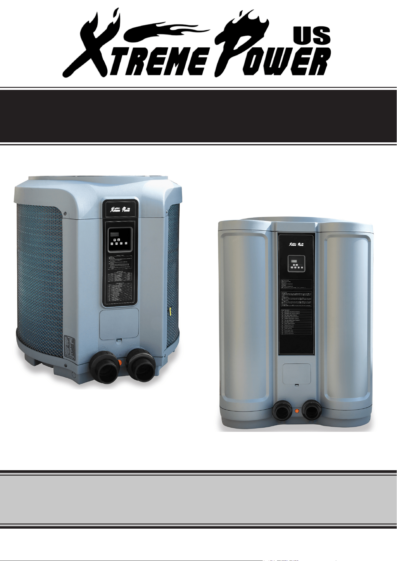
POOL HEAT PUMP
SAVE THIS MANUAL: KEEP THIS MANUAL FOR SAFETY WARNINGS, PRECAUTIONS, ASSEMBLY,
OPERATING, INSPECTION, MAINTENANCE AND CLEANING PROCEDURES. WRITE THE PRODUCT’S
SERIAL NUMBER ON THE BACK OF THE MANUAL NEAR THE ASSEMBLY DIAGRAM (OR MONTH
AND YEAR OF PURCHASE IF PRODUCT HAS NO NUMBER).
OWNER’S MANUAL AND SAFETY INSTRUCTIONS
ITEM #75210 (53000 BTU/H) - 75212 (137000 BTU/H)
FOR QUESTIONS PLEASE CALL OUR CUSTOMER SUPPORT: (909) 628 0880 MON-FRI 9AM TO 3PM PST
GENERAL SAFETY WARNINGS
1
WARNING -TO REDUCE THE RISK OF INJURY,do not permit children to use this product unless
they are closely supervised at all times.
IMPORTANT SAFETY INFORMATION
Read all safety warnings and instructions. Failure to follow the warnings and instructions may result
in electric shock, re and/or serious injury. Save all warnings and instructions for future reference.
The warnings, precautions, and instructions discussed in this instruction manual cannot cover all possible
conditions and situations that may occur. It must be understood by the operator that common sense and
caution are factors which cannot be built into this product, but must be supplied by the operator. Read
carefully and understand all ASSEMBLY AND OPERATION INSTRUCTIONS before operating. Failure to
follow the safety rules and other basic safety precautions may result in serious personal injury.
CAUTION - To reduce the risk of electric shock the pool must be installed no closer than 6 feet (1.8
m) from any electrical outlet. Do not place portable appliances closer than 5 feet (1.5 m) from the
pool.
DO NOT BURY CORD. Locate cord to minimize abuse from lawn mowers, hedge trimmers, and
other equipment.
WARNING-To reduce the risk of electric shock, replace damaged cord immediately.
WARNING-To reduce the risk of electric shock, do not use extension cord to connect unit to electric
supply; provide a properly located outlet.
SAVE THESE WARNINGS
FOR USE WITH SWIMMING POOLS ONLY.
CAUTION: TO ENSURE CONTINUED PROTECTION AGAINST SHOCK HAZARD, USE ONLY
IDENTICAL REPLACEMENT PARTS WHEN SERVICING.
WARNING: RISK OF ELECTRIC SHOCK. CONNECT ONLY TO A GROUNDING TYPE RECEPTACLE.
The pool heat pump is a self-contained unit designed specically for pool heating. Each component has been
selected with care to achieve a high-quality product in an effort to exceed all industry standards. All pool
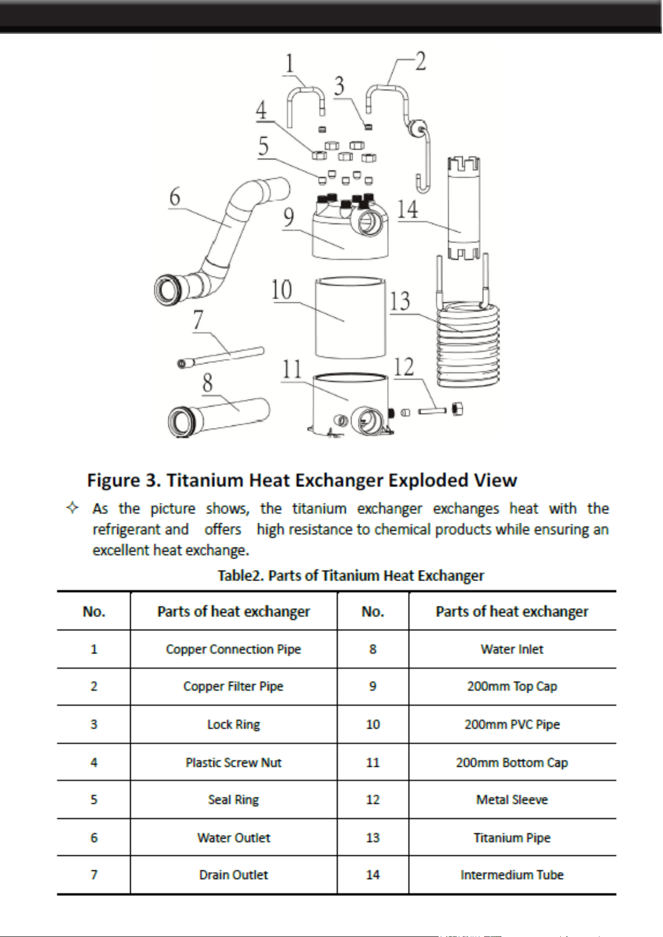
heat pumps have an electronic board with service analyzer, a titanium heat exchanger tube warranted for 10
years against corrosion and PVC plastic cabinet that eliminates all maintenance for life. All components are
of superior quality, which presents you with an effective heat pump.
Compared to other types of pool heaters, such as gas or oil-red, the pool heat pump has a lower heating
capacity on a BTU/h basis. Therefore, it needs to operate for a longer time to accomplish the desired results.
Occasionally, it may be necessary to run the heat pump for up to 24 hours per day. However, this should not
be of concern to the owner because the heater is designed to operate continuously. What’s more, despite
continuous operation, it will still heat the pool far more economically than other types of heaters. As with all
pool heaters, you are advised to use a pool cover at night and when the pool is not in use. The pool cover
should be used if night temperatures are 15°F less than desired pool temperature. This will keep evaporation,
the greatest source of heat loss, to a minimum, thus greatly reducing the overall pool heating costs. During
warmer weather, the pool cover may not be required.
INTRODUCTION
2
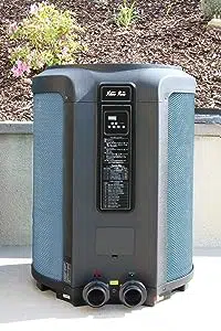
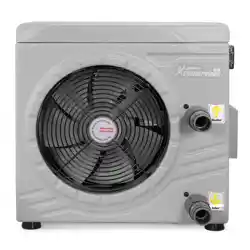
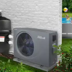
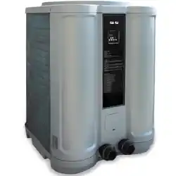
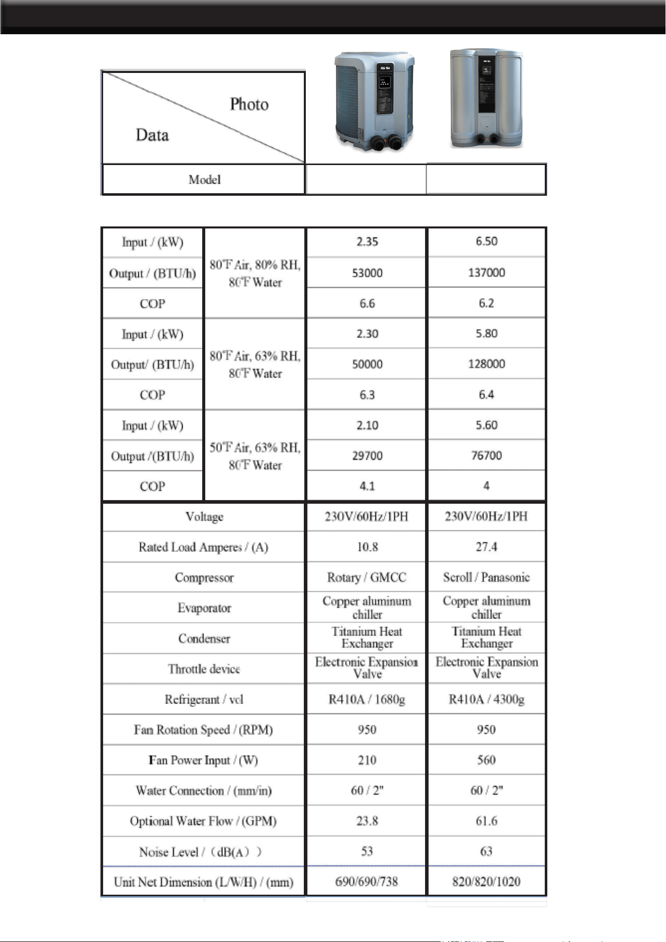
PRODUCT INFORMATION
7521275210
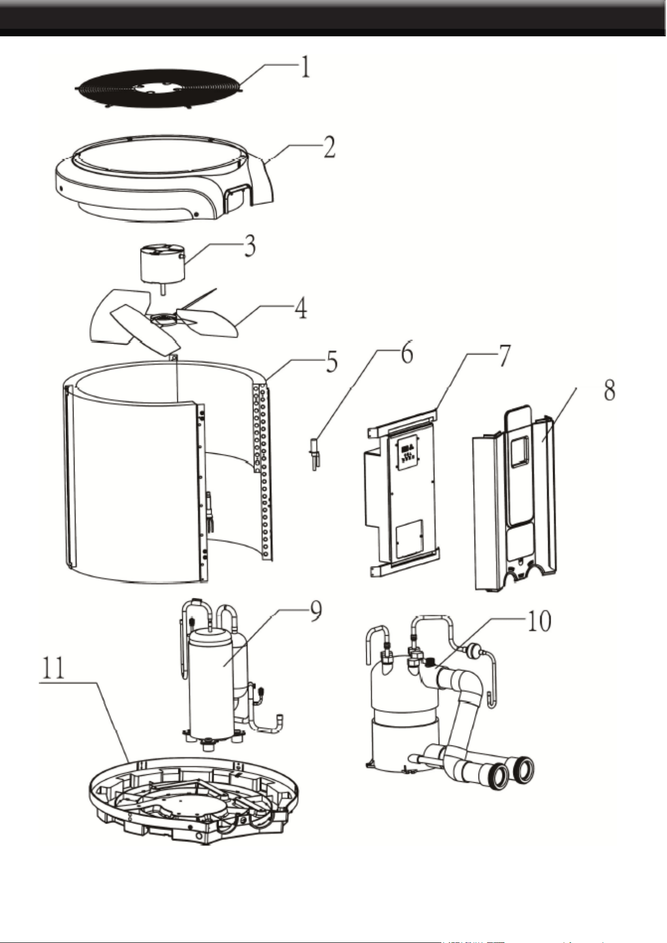
PARTS INFORMATION
75210
3
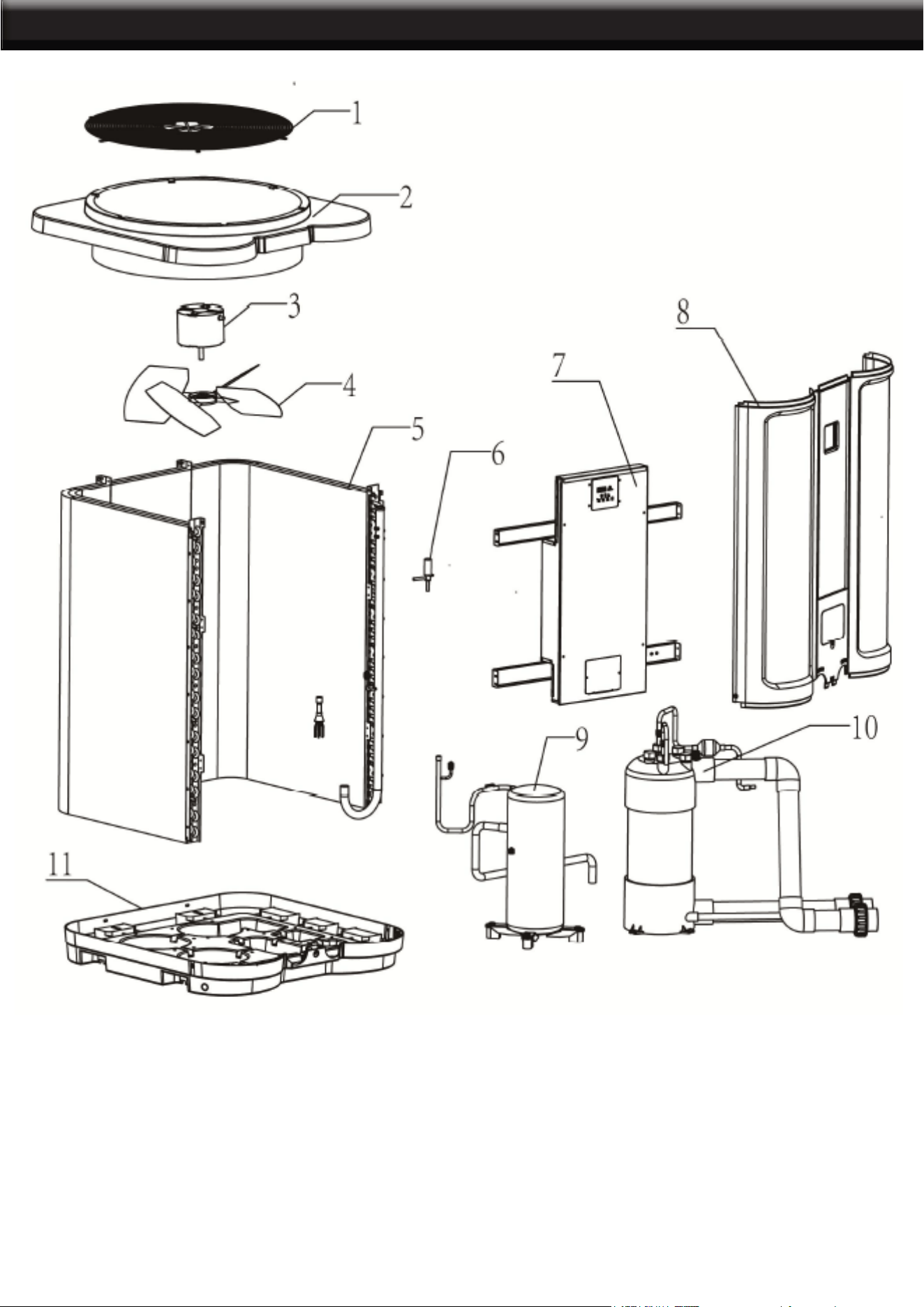
PARTS INFORMATION
75212
1. Fan Guard
2. Roof Cover
3. Fan Motor
4. Fan Blade
5. Cooper Aluminum Chiller
6. Electrical Expansion Valve
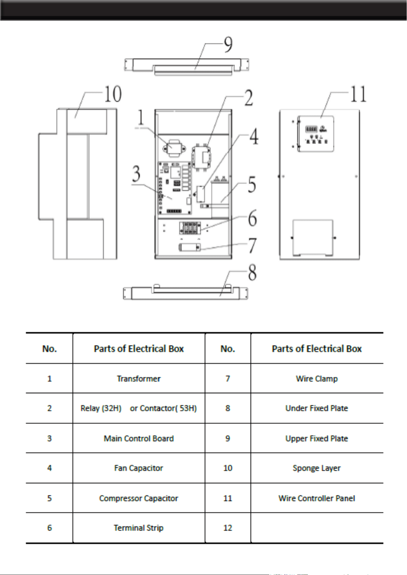
7. Electrical Box
8. Front Panel
9.Compressor
10. Titanium Heat Exchanger
11. Chassis
4
PARTS INFORMATION
75210
5
PARTS INFORMATION
75212
6
INSTALLATION
7
LOCATION
The placement of the pool heater is very important in keeping installation costs to a minimum
while providing for maximum efciency of operation, as well as allowing adequate access for
service and maintenance.
The pool heat pump is designed for outdoor installation and should not be installed in a fully
enclosed area, such as a shed, garage, etc. Recirculation of cold discharged air back into the
evaporator coil will greatly reduce unit heating capacity and efciency.
The
unit should be located as close as practical to the existig pool pump and lter to minimize
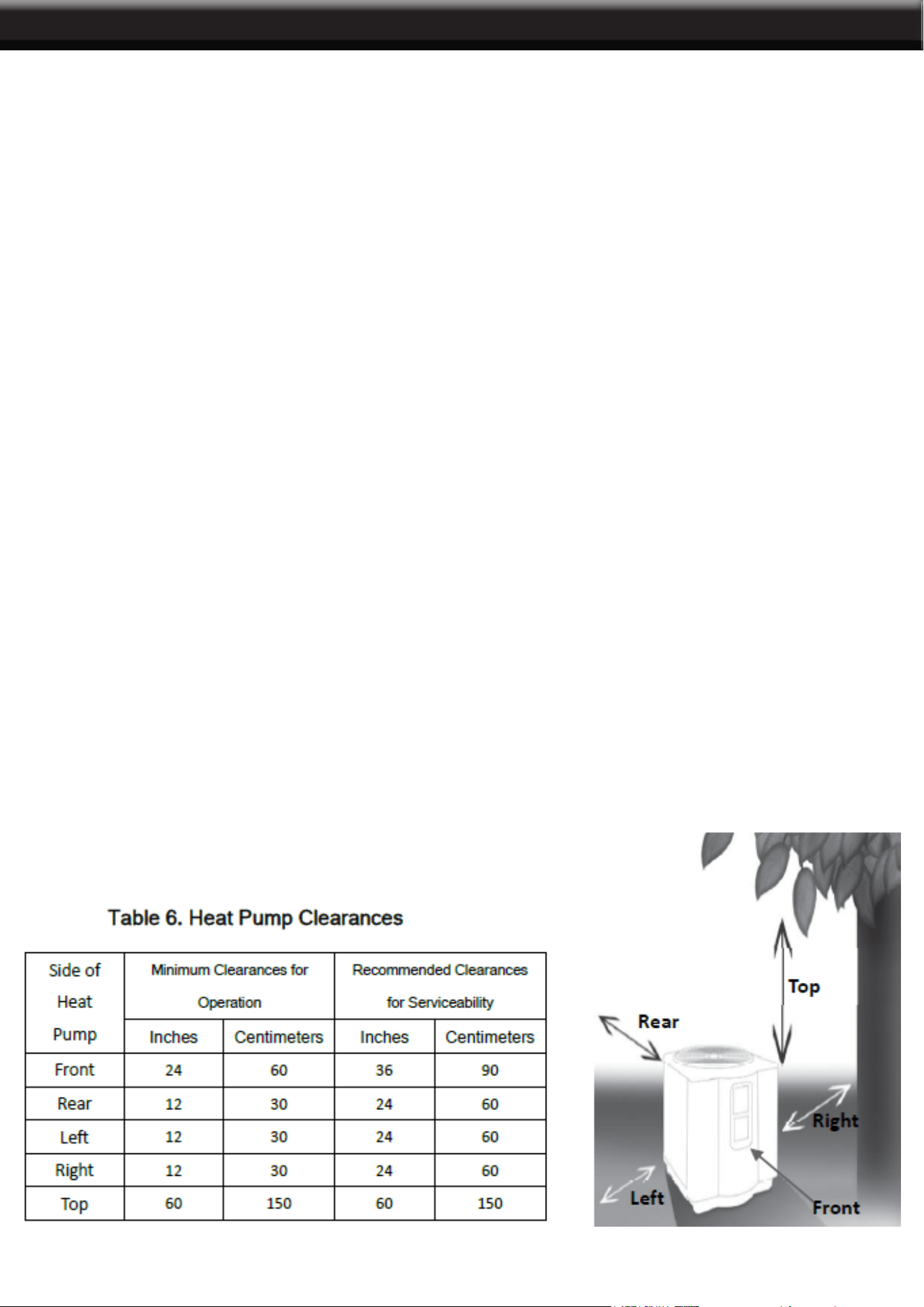
water piping. However, do not forget to provide a clearance(Table 6) at the very least all
around your heat pump. The use of 90 degree bends and short radius elbows in the water
piping should be kept to a minimum.
Mount the unit on a sturdy base, preferably a concrete slab or a set of blocks. The base
should be completely isolated from the building foundation wall to prevent the possibility of
sound or vibration transmission into the building. The size of the base should not be less than
the size of the heat pump.
IMPORTANT
• Air is pulled through the evaporator coil and discharged through the top grille.
• A minimum clearance of 60 inches should be allowed above the unit for unrestricted air
discharge. The unit must not be installed under a porch.
• Any side of the unit should be located at least 24 inches from a wall or from any other
obstruction for unrestricted air intake and service access.

INSTALLATION
8
WATER PIPING
Single Unit Installation
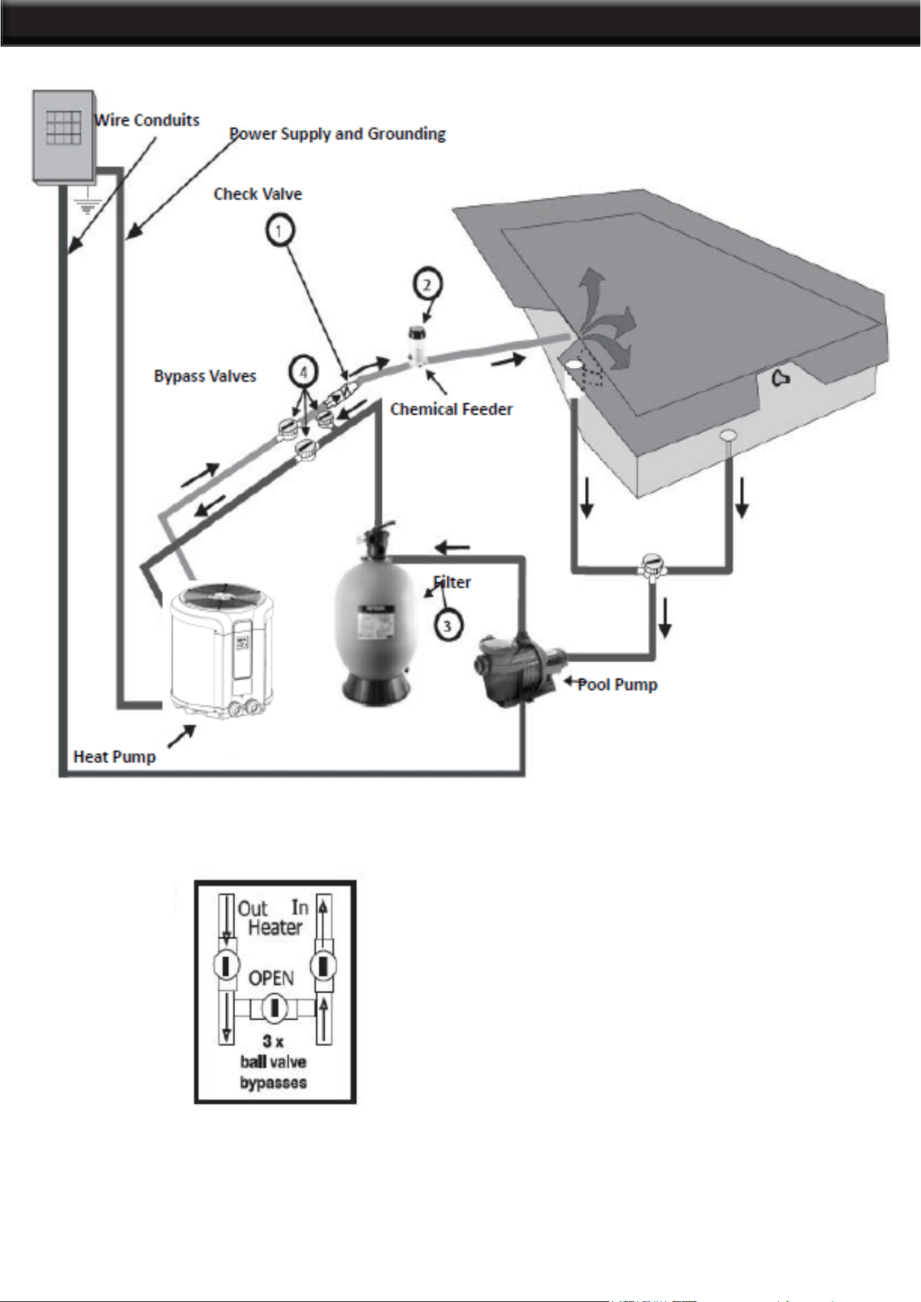
Figure 6 illustrates the standard plumbing layout with a single heat pump unit. Following the
diagram from right to left, the plumbing sequence is as follows: Pool > Pool Pump > Filter >
Heat Pump > Check Valve > Chemical Feeder > Pool. Note For normal installations, do not
install a shutoff valve or any kind of variable restriction in the water piping between the heat
pump outlet and the pool/spa.
Filtered water is plumbed to the inlet, located on the right side of the heat pump front panel.
Heated water ows through the outlet, located on the left side of the heat pump front. Two
inch unions are provided.
Automated chlorine distribution systems, if used, must be placed downstream of the heater
to minimize harm to the pool equipment. Use rigid PVC piping if possible. All joints should be
glued with PVC glue. When the piping installation is complete, operate the pool pump and
check the system for leaks. Then, check the lter pressure gauge to verify that there isn’t any
indication of excessive pump head pressure. You can also make the connections using high-
pressure exible hose, but make sure the hose can withstand high pressure. The installation
of a heat pump bypass is not necessary unless the water ow exceeds 75 GPM.
MULTIPLE UNIT INSTALLATION
Heat Pump and Heater Combination
In certain regions of the country it may be more economical to run a heat pump during the
warmer months and a gas heater during the cooler months. In some situations it may be
desirable to run the heat pump in the “Chiller” mode during the hottest portion of the year and
a heater during the cooler months. The heat pump may be plumbed with a gas or electric
heater or any combination of heat sources including solar. All heat sources must be plumbed
in series to work correctly
and efciently.
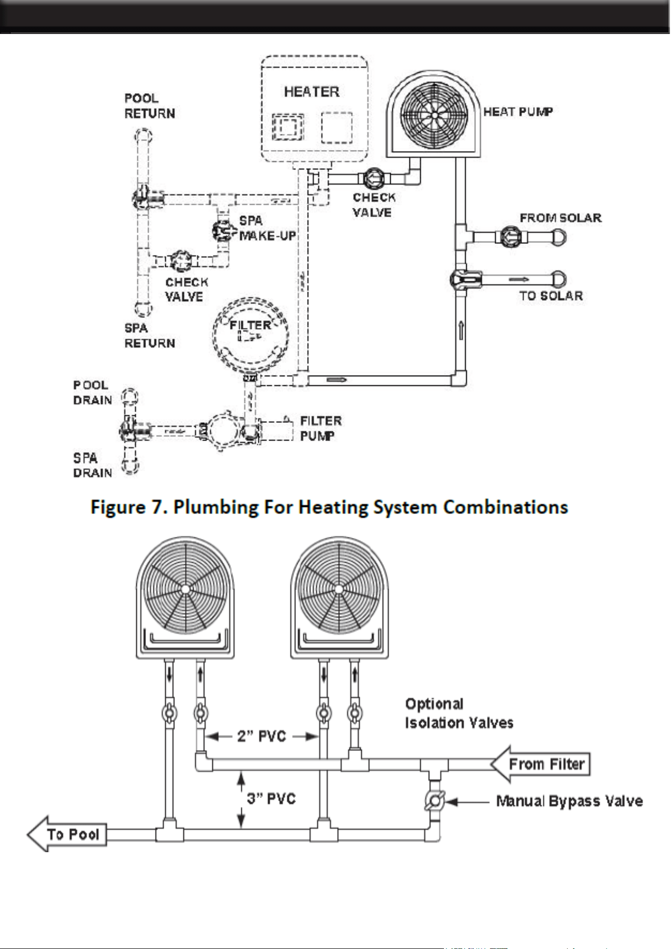
Figure 7 illustrates a recommended plumbing layout for a heat pump / heater / solar
combination heating system for a pool / spa combination. Your system may not contain all
of these components, but the basic plumbing will apply by eliminating the component in the
illustration that is not a part of your system.
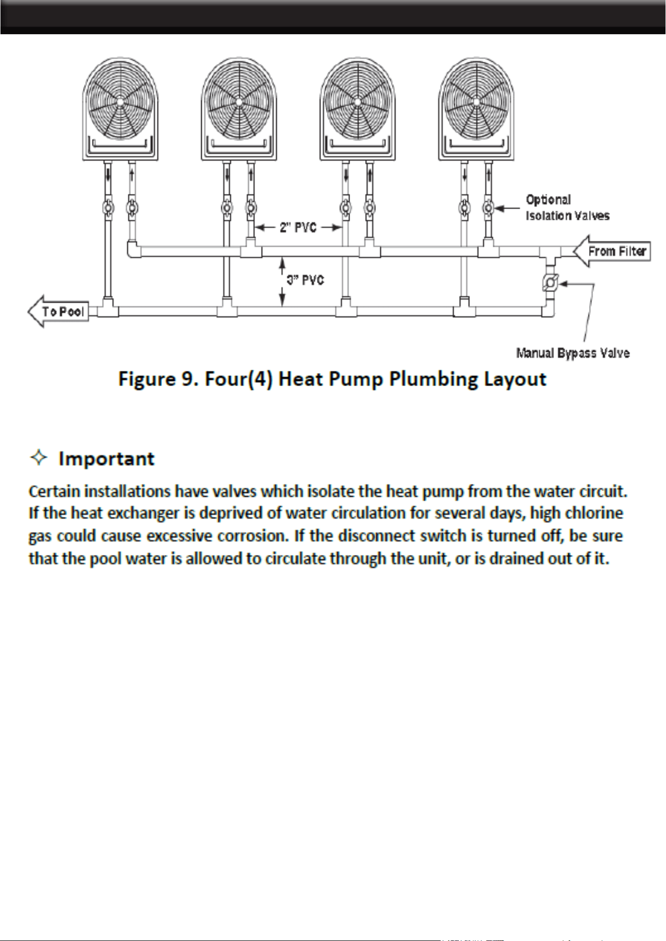
MULTIPLE HEAT PUMP CONNECTIONS
All plumbing on multiple heat pump installations must be done in parallel (see Figures 8 and
9). An equal ow of water to each heat pump is important for optimum operation.
Note: It may be necessary to adjust water pressure switch if a unit is installed below the
water level. See Section 5.6 for details on when and how to adjust the pressure switch. Each
heat pump allows a maximum ow rate of 70 gpm (265 lpm) and requires a minimum of 20
gpm (76 lpm).
9
STANDARD PLUMBING LAYOUT
10
HEAT PLUMBING PUMP LAYOUT
HEAT PLUMBING LAYOUT
11

ELECTRICAL CONNECTIONS
ELECTRICAL
The wiring of your pool heat pump should be performed by a qualied electrician in accordance
with local requirements. A properly-sized breaker and copper wire must be used. Check the
heat pump data label for required maximum breaker size.
IMPORTANT
The unit must always be powered off before opening the access panel.
BONDING
Because all metals have different electrical potentials, all metal and electrical components of
the pool system must be bonded together. This includes the metal framework of the pool, the
light, the pump, the lter (if made out of metal), the heater, any automatic chlorine generator,
and any other metal or electrical equipment. On some older pools, this substructure bond
wire may not exist. In these cases, a 6 to 8 foot solid copper rod must be driven into the
ground near the
equipment. All electric and metal components must then be bonded to each other, and then
to the copper rod.
IMPORTANT
² Check valve must be installed between the heater and any automatic chlorine distribution
system (if used);
² Any kind of automatic chlorine distribution system must be installed after or downstream of
the heat pump;
² The lter must be placed before or upstream from the heat pump;
² A bypass and shut-off should be installed on all systems for ease of service, maintenance
and to balance the water ow. Bypasses must be installed on any system with over a 3/4 HP
pool pump.
The installation of the pool heater should be performed by a certied electrician. To connect
the electricity, you must unscrew the two screws under the front panel, then slide the electric
cable through the knock out located on the left or the right side of the base, and then insert
it in the control box.
12
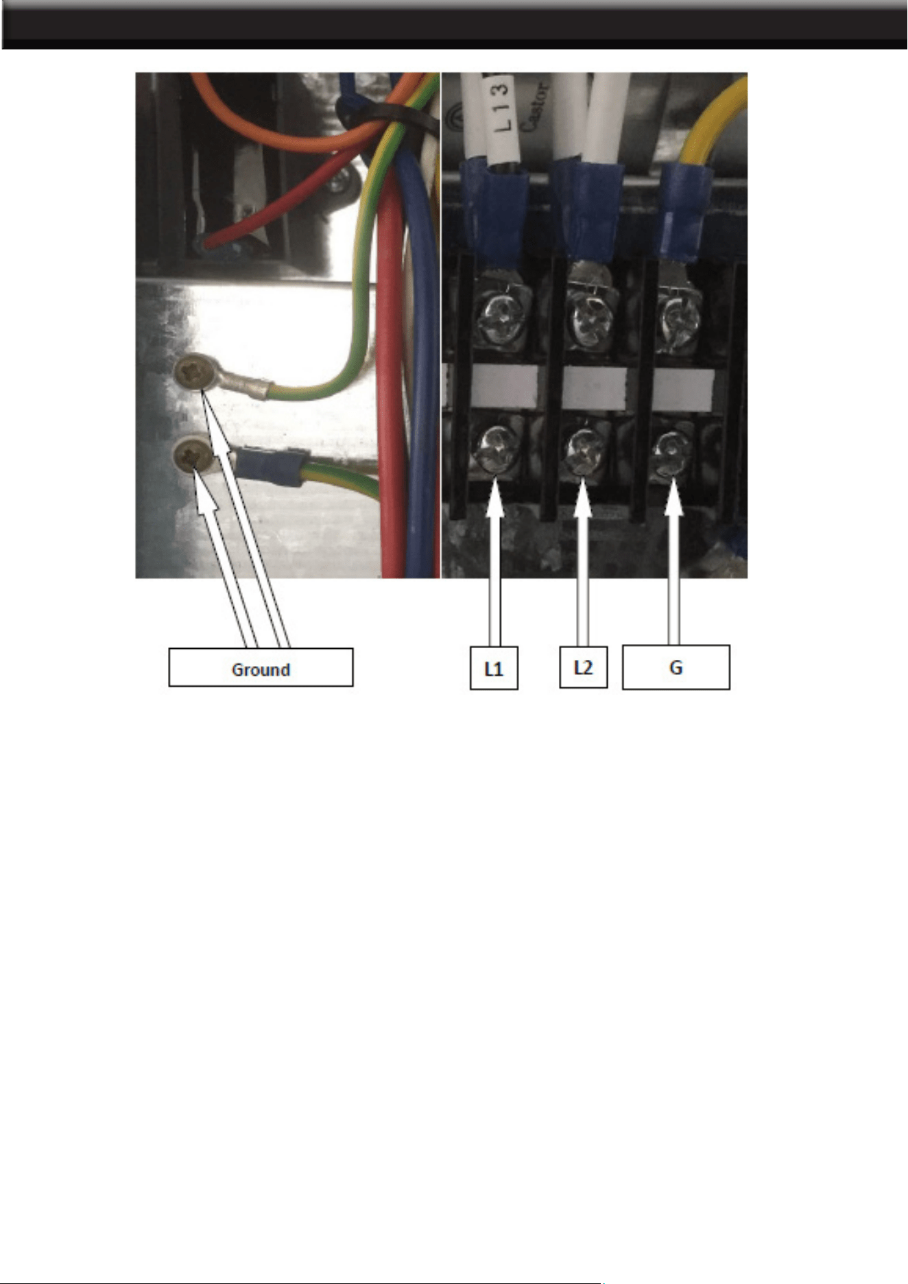
ELECTRICAL SUPPLY OF ELECTRICAL BOX
POWER REQUIREMENTS : 230VAC, 1PH, 60HZ
Look at the nameplate located on the heat pump to know the required amperage
Please refer to your local electrical code for additional wiring requirements
13
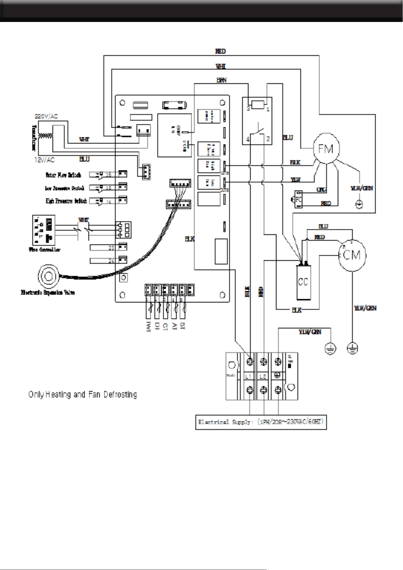
ELECTRICAL SUPPLY OF ELECTRICAL BOX WIRING DIAGRAM
14
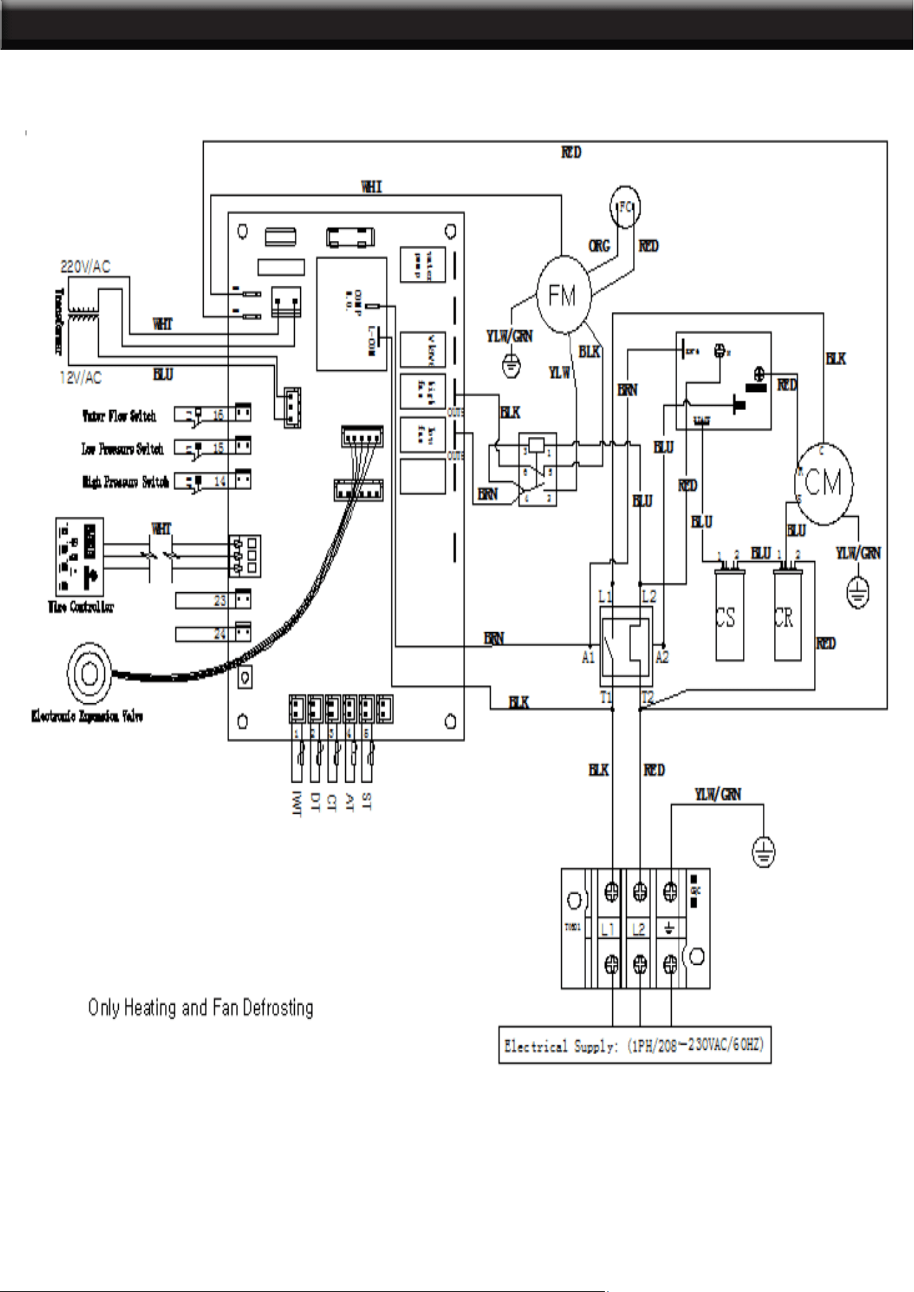
WIRING DIAGRAM
75212
15
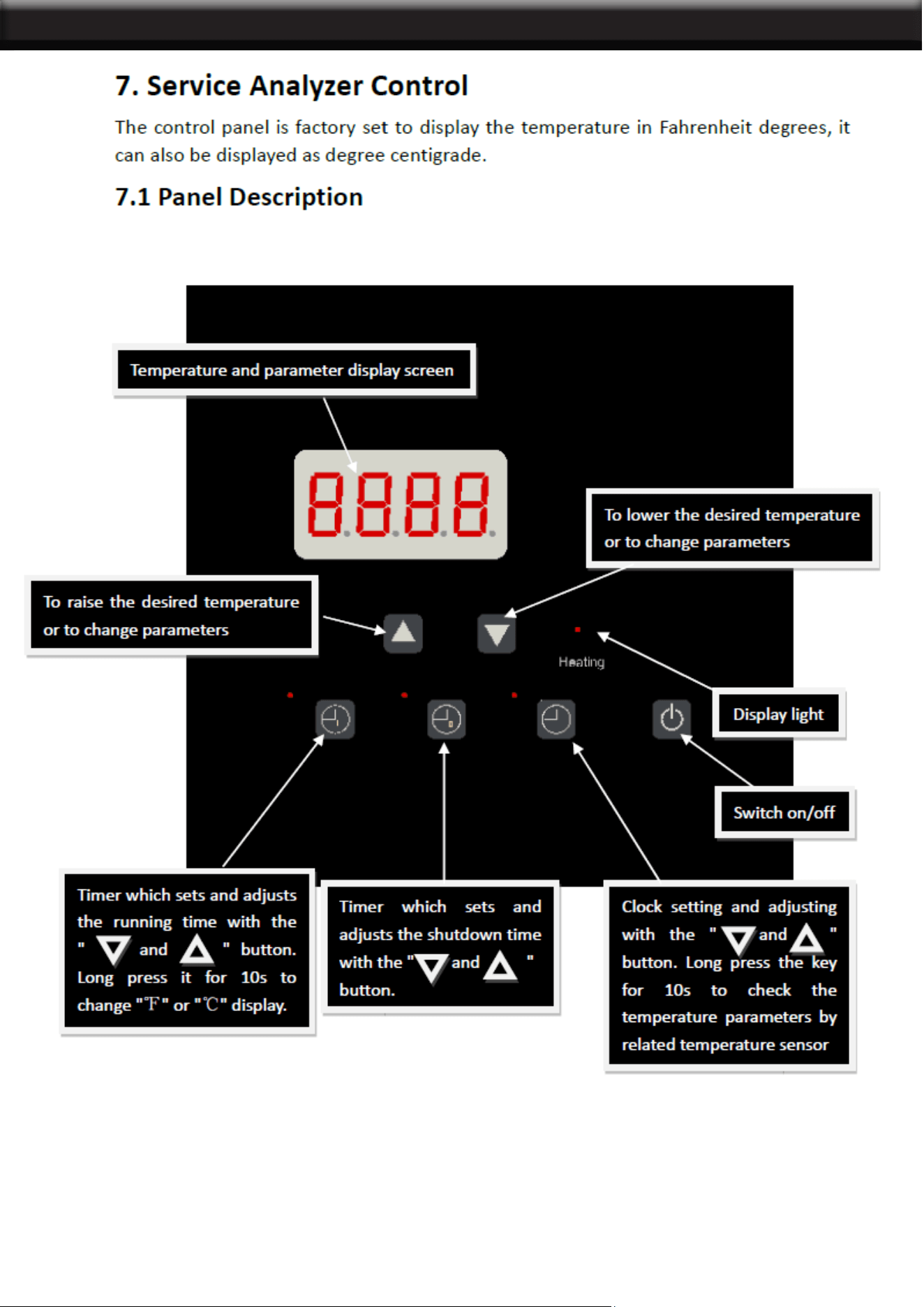
SERVICE ANALYZER CONTROL
16
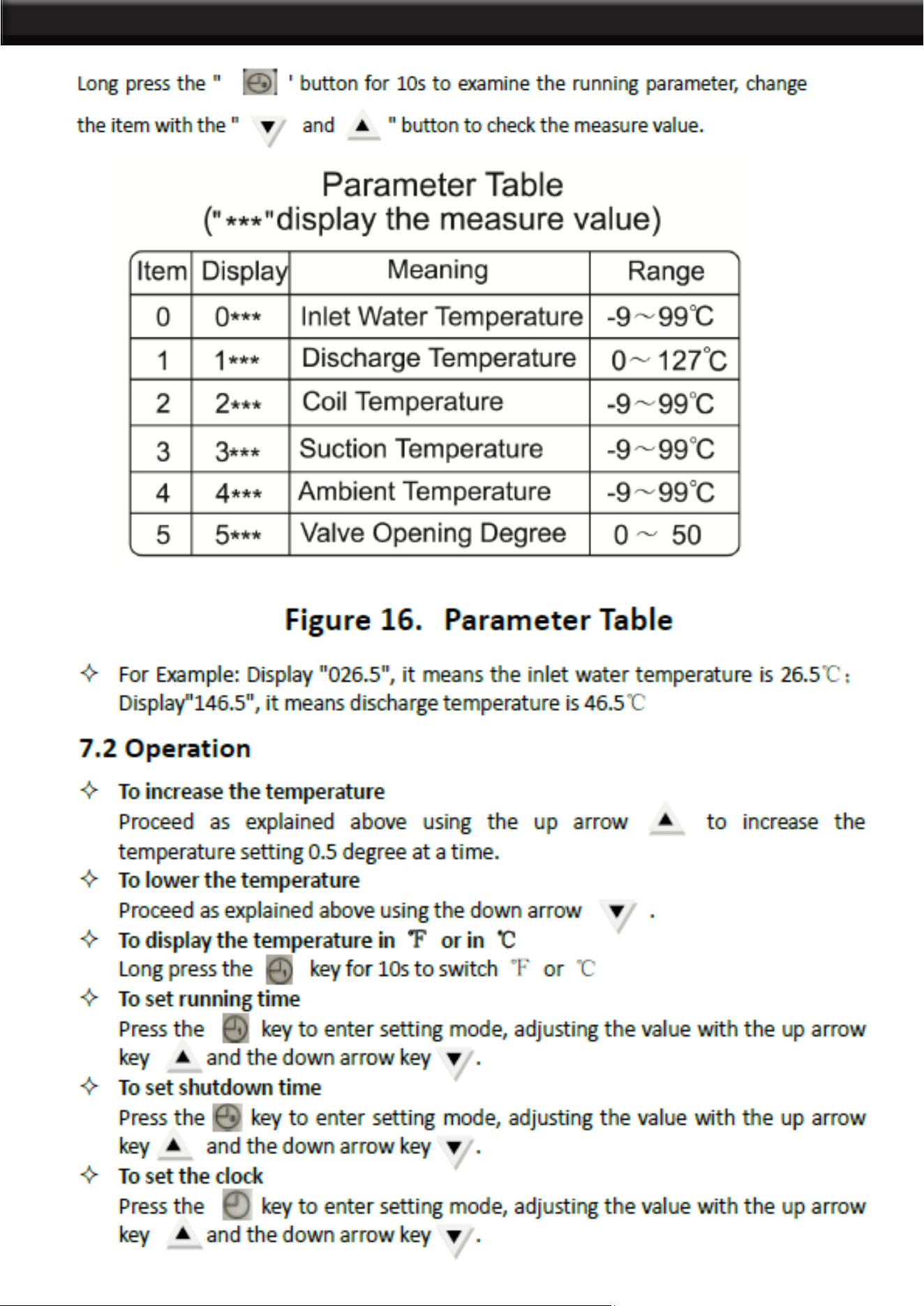
SERVICE ANALYZER CONTROL
17
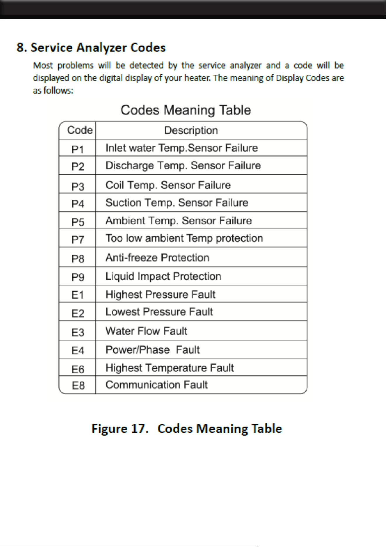
SERVICE ANALYZER CONTROL
18
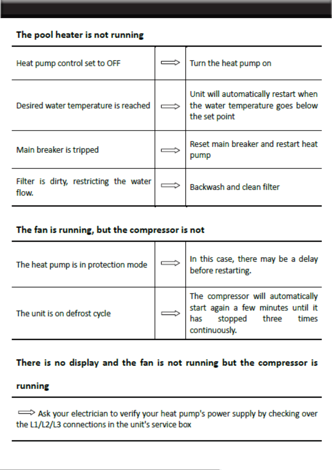
TROUBLESHOOTING
19
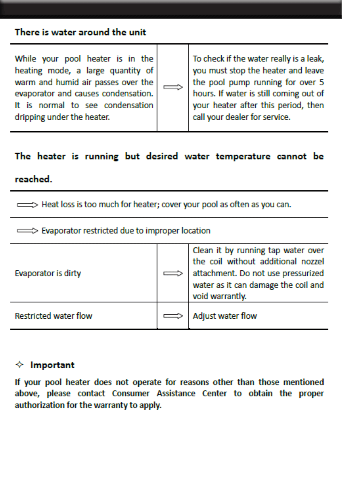
TROUBLESHOOTING TROUBLESHOOTING
20

OPERATION AND MAINTENANCE
Initial Startup
² Before starting the pool heater for the rst time, it is important to verify that the breaker is in
the ON position.
² Also make sure that the water circulates freely and that the pool pump is activated.
² Then, you will need to set the water temperature you desire. The fan will immediately start.
The compressor will start after a 3 to 4-minute delay.
² When the compressor is running, the "heating" indicator located on the right (see “Service
Analyzer Control,” p. 13) should be lit. At initial startup, it is normal for the unit to run 24 hours
a day.
² It is also normal to see water dripping from the holes at the base of the unit. This is just con-
densation.
MAINTENANCE
² Dirt can accumulate on the evaporator. You can easily remove it by using a non-pressured
water spray without damaging the small aluminum ns.
² The cleaning of the plastic cabinet can be done with the help of a brush and soap.
WINTERIZING
² First, you must turn the breaker off. The unit must be drained of all its water. You will need to
disconnect the IN and OUT water connections. Then the unit must be tilted or blown out with
air until all water is out.
² The next step is to reconnect your IN and OUT water connections that will have previously
been drained.
² It is recommended to cover the heat pump to prevent snow from getting inside, so a protective
winter cover is also needed.
21

OPERATION AND MAINTENANCE HEAT PLUMBING PUMP LAYOUT
RECORD YOUR MODEL’S INFORMATION
Please complete and mail in the ownership registration card provided with this guide. The
return address is displayed on the front of your registration card. Simply mail it as you would
a postcard. The card helps us notify you about any new information about your heater.
Whenever you call to request service for your heater, you must know your complete model
and serial numbers. You can nd this information on the plate located at the base of your
heater.
Please also record the purchase date of your device and your dealer’s name, address,
and telephone number.
Model Number ____________________________________________________
Serial Number _____________________________________________________
Purchase Date ____________________________________________________
Dealer Name ______________________________________________________
Dealer Address ____________________________________________________
Dealer Phone _____________________________________________________
Keep this book and the sales slip together in a safe place for future reference.
NOTES:
22
PLEASE READ THE FOLLOWING CAREFULLY
THE MANUFACTURER AND/OR DISTRIBUTOR HAS PROVIDED THE PARTS LIST AND ASSEMBLY
DIAGRAM IN THIS MANUAL AS A REFERENCE TOOL ONLY. NEITHER THE MANUFACTURER OR
DISTRIBUTOR MAKES ANY REPRESENTATION OR WARRANTY OF ANY KIND TO THE BUYER
THAT HE OR SHE IS QUALIFIED TO MAKE ANY REPAIRS TO THE PRODUCT, OR THAT HE OR
SHE IS QUALIFIED TO REPLACE ANY PARTS OF THE PRODUCT. IN FACT, THE MANUFACTURER
AND/OR DISTRIBUTOR EXPRESSLY STATES THAT ALL REPAIRS AND PARTS REPLACEMENTS
SHOULD BE UNDERTAKEN BY CERTIFIED AND LICENSED TECHNICIANS, AND NOT BY THE
BUYER. THE BUYER ASSUMES ALL RISK AND LIABILITY ARISING OUT OF HIS OR HER REPAIRS
TO THE ORIGINAL PRODUCT OR REPLACEMENT PARTS THERETO, OR ARISING OUT OF HIS OR
HER INSTALLATION OF REPLACEMENT PARTS THERETO.
Note: Some parts are listed and shown for illustration purposes only and are not available
individually as replacement parts.
Record Product’s Serial Number Here:
Note: If product has no serial number, record month and year of purchase instead.
23
DISCLAIMER
PRODUCT MADE IN CHINA