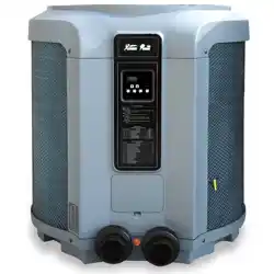
The Swimming Pool Heat Pump Unit is intended to heat the swimming pool water and regulate the
temperature. Use in any other application will void the warranty.
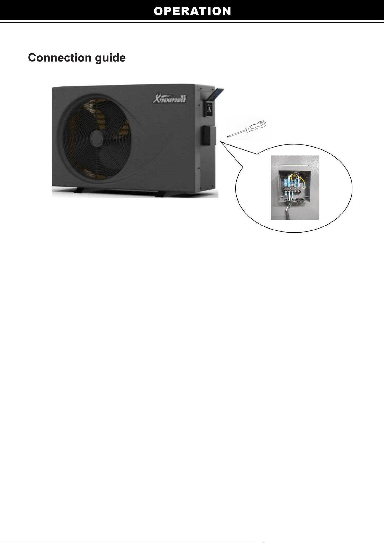
The inlet & outlet connections cannot support any load from
Make certain the air outlet is not directed towards any person, animal, or vegetation.
The ed off opening the access panel. Always turn of circuit supplying power
to the unit prior to removing the access panel or performing any electrical work on the unit.
All electrical connections must performed a d electrician and according to national and local
electrical codes. We have provided important safety messages in this manual and on your heat pump. Always
read and all safety messages.
You will need to set the water temperature you desire.
Always ll the machine outdoors, while adhering to the minimal clearances needed for proper operation
and heating. DO NOT place the unit next , fences, etc. which can air inlet. These locations
deny the unit a continuous source of fresh air which reduces its ncy and may prevent adequate heat
delivery.
Heat Pumps accordance the
local codes, refer to the edition of the Canadian Electrical Code (CEC).
The unit will automatically when there is proper and
the extended period of time or winterized, it must drained of all water. You will need
to disconnect and OUT water connections. Then the unit then tilted or lown out with air until all
water is out.
the air outlet. Do not attempt to disas the fan at any time.
at any time there is noise, odor, smoke, electricity power
immediately and contact your local dealer. All repairs performed y a qua technician.
co near unit.
1
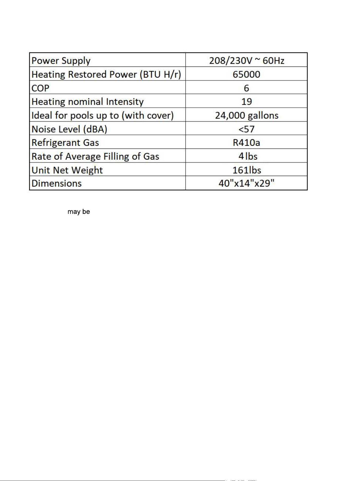
Note: There variations in values due to climatic conditions.
2
SWIMMING
POOL WATER
TREATMENT
SYSTEM
STOP VALVE
STOP VALVE
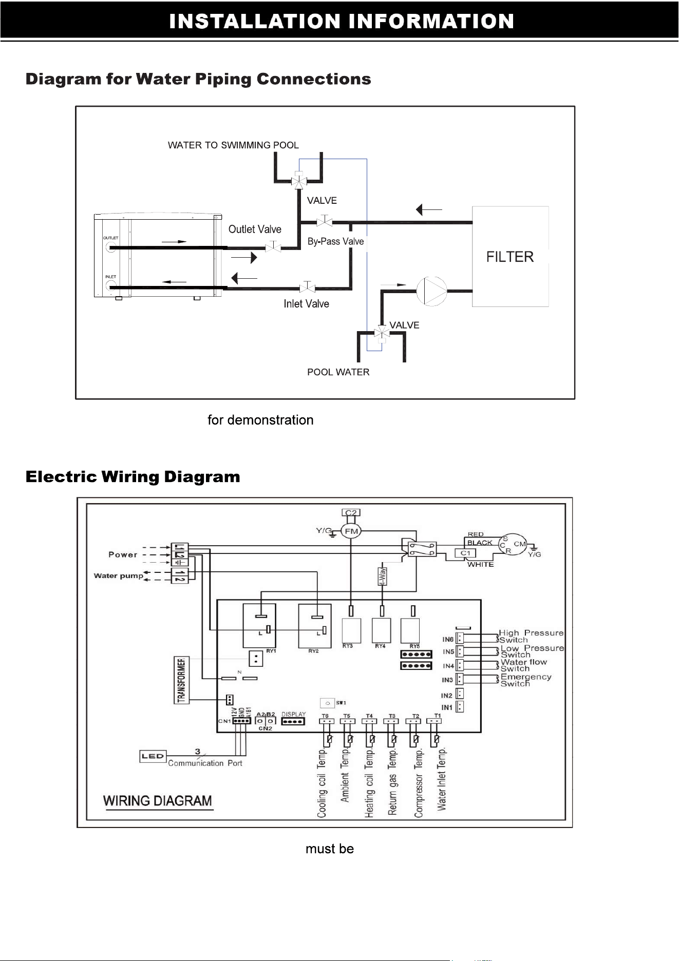
Note: The diagram is purposes only, and layout of the pipes
is for reference only.
Note: The swimming pool heat pump grounded.
THREE WAY
Pump
THREE WAY
3
All electrical connections e performed a qu electrician and according to national and
local electrical codes. We have provided important safety messages in this manual and on your heat
pump. Always read and o
all safety warnings d in accordance with
all local codes, refer to edition of the
Canadian Electrical Code (CEC).
the minimal clearances needed for proper
operation and heating. DO NOT place the unit next to fences, etc. which the air
inlet. These locations impede the unit a continuous source of fresh air which reduces its
and may prevent adequate heat delivery.
Mount the unit on a and a concrete s
completely isolated from the foundation wall to prevent the y of sou
transmission into the
.
The pool heat pump is designed for o tion only and should not fully
enclosed area, such as a shed, garage, etc. Recirculation of c into the
evaporator coil will greatly reduce unit heating capacity Air is pulled through the
evaporator coil and discharged through the side grille. A minimum clearance of 98 inches should
allowed on the air outlet side air discharge. The unit not under a
porch. Any other side of the unit should at least 28 inches from a wall or from any other
air intake and service access.
Breaker Rated Current : 20 A
Breaker Rated Residual Action Current : 30 mA
Fuse : 25 A
Power Cord : 3X12
: 3X20
Note:
4
The piping sequence is as follows: pool > pool pump > er > heat pump > check valve >
chemical feeder pool. Automated chlorine n s if used, placed
downstream of the heat pump to minimize harm to the pool equipment. Use rigid PVC piping if
po (SCH40 or SCH80). All should glued with PVC glue. When the piping
is complete, operate the pool pump and check the s for leaks. Then, check
the er pressure gauge to verify that there isn’t any indication of excessive pump head
pressure.
You can also make the connections using high-pressure hose, sure the hose
can
see water dripping from the drain at the ase pan of the unit. While your
pool heat pump is in the heating mode, a large volume of warm and humid air passes over
the evaporator and causes condensation. To determine if there is a leak, you the
heat pump and leave the pool pump running for at minimum 5 hou water
out of your heat pump after this period, then call your dealer for service
.
The wiring of your pool heat pump s performed a q electrician in
accordance with local requirements. A properly-sized and copper wire used.
Check the heat pump data required maximum all metals have
electrical potentials, all metal and electrical components of the pool must
together. This includes the metal framework of the pool, the light, the pump, the de
out of metal), the heat pump, any automatic chlorine generator, and any other metal or
electrical equipment. On some older pools, this s ond wire may not exist.
these cases, a 6 to 8 foot solid copper rod driven into the ground near the
equipment. All electric and metal components then to each other, and then to
the copper rod.
The wiring of your pool heat pump performed a electrician in
accordance with national and local requirements
.
Set leakage protector according to the local code for wiring (leakage operating current
30mA)
.
The layout of signal uld derly and not other.
Once all wiring and connections have checked power to the unit
on.
5
6
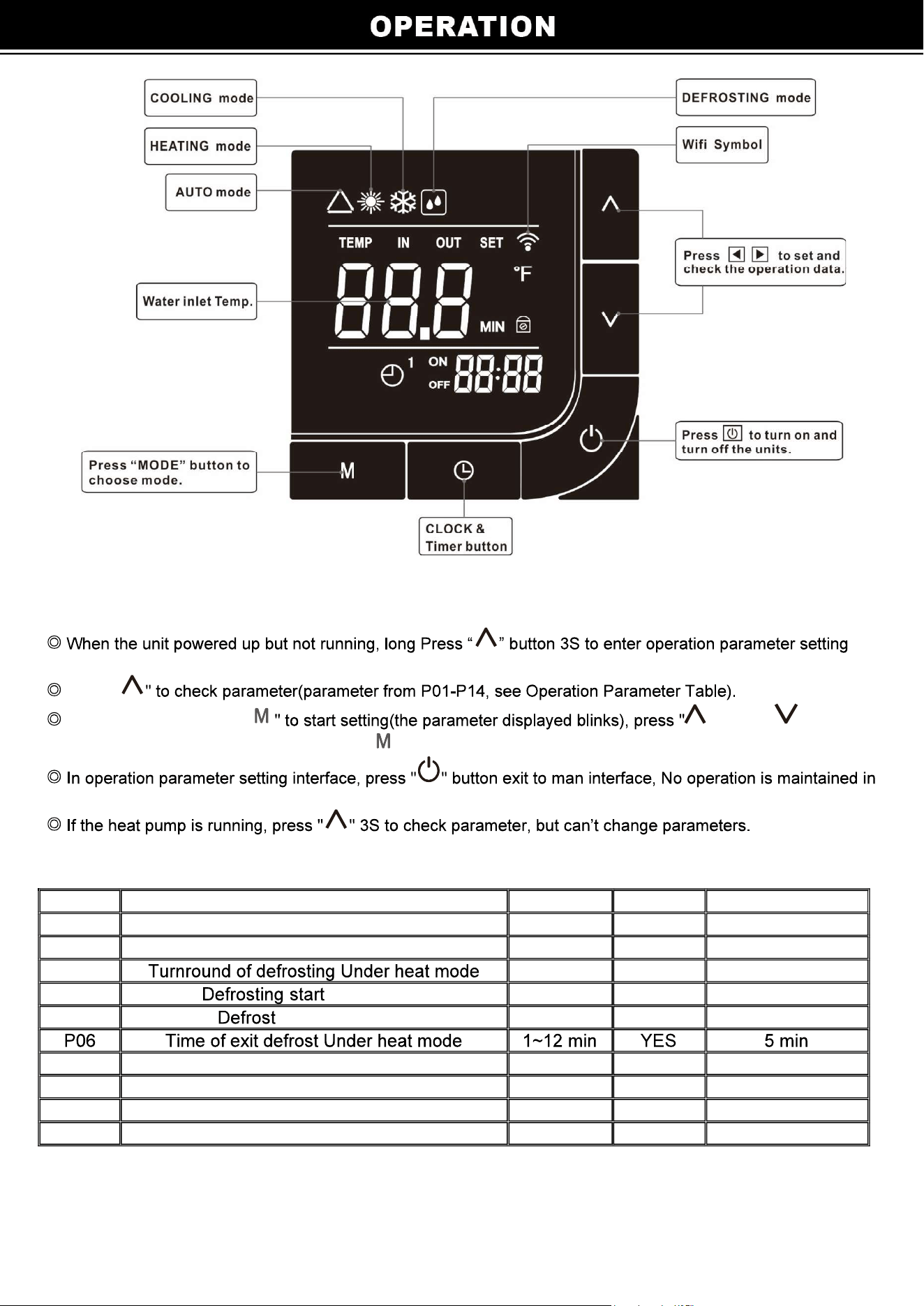
Set the operation parameter:
interface.
" " to set
Press "
Under parameter, press " " or
data for parameter from P01-P14, press " " again to exit the current parameter settings.
the parameter interface.
NO Meaning Range Change Factory setting
P01 Cooling setting water temperature 50~113°F YES 79°F
P02 Heating setting water temperature 50~113°F YES 79°F
P03 30~90 min YES 45min
P04 temperature 32~86°F YES 19°F
P05 exit temperature 30~86°F YES 56°F
P07 Mode (cool/cool & heat/E-heat/heat) 0/1/2/3 YES 1
P08 EEV manual/automatic 0/1 NO 1
P09 Heating Target Superheat 5~59°F NO 34°F
P10 Cooling Target Superheat 5~59°F NO 25°F
7
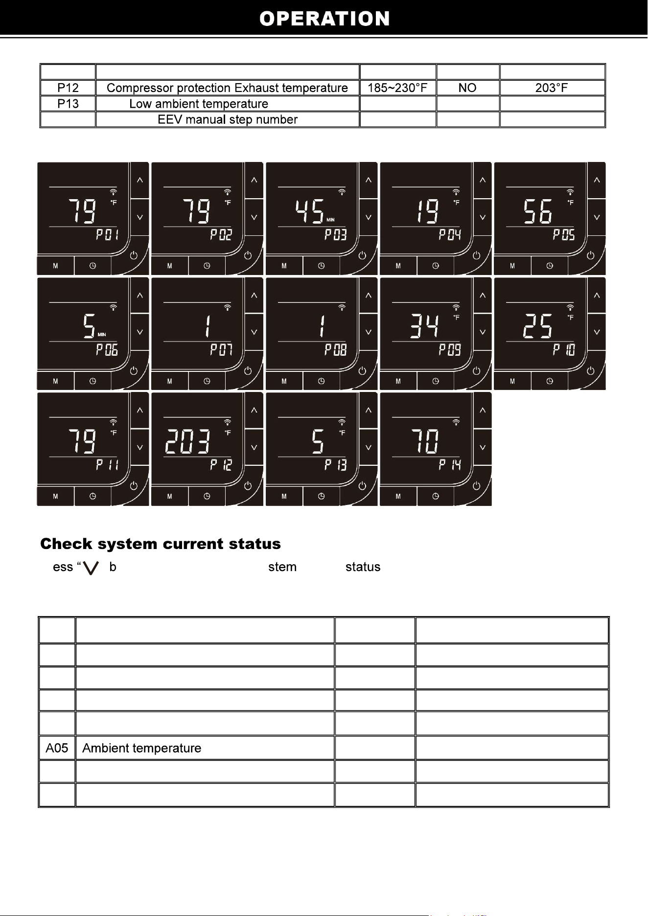
P11 Auto mode setting water temperature 50~113°F YES 79°F
protection -4~50°F YES 5°F
P14 18~94 NO 70
Pr ” utton 3S to enter check sy current interface.
NO Meaning Range
Remarks
A01 Water temperature -4~210°F
Measured value
A02 Compressor Exhaust temperature -4~257°F
Measured value
A03 Heating coil temperature -4~210°F
Measured value
A04 Return gas temperature -4~210°F
Measured value
-4~210°F
Measured value
A06 Cooling coil temperature -4~210°F
Measured value
A07
Manual Control for EE valve
18~94
Measured value
8
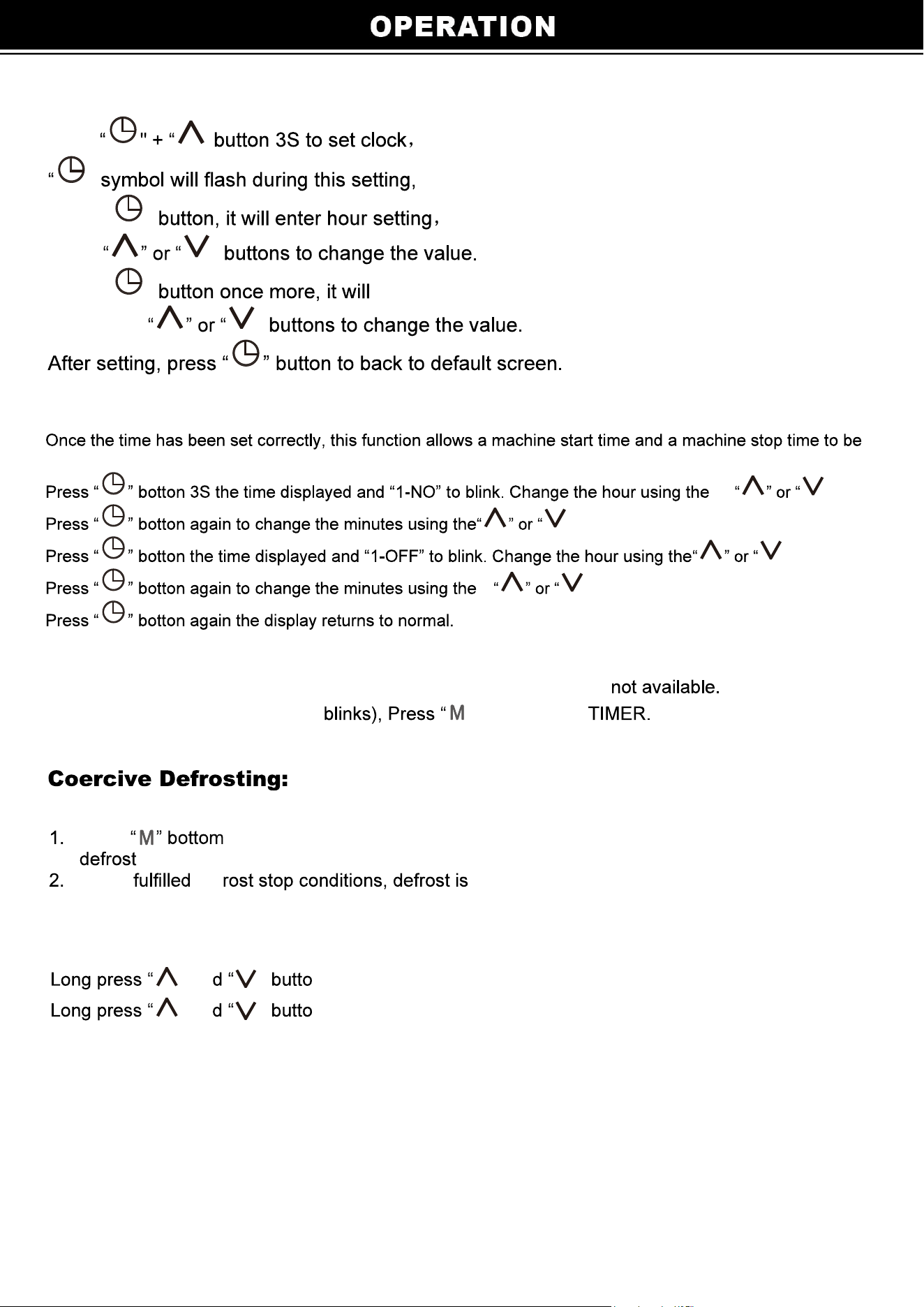
Real-time clock setting
Press ”
"
Press " "
press ”
Press " " enter minute setting.
Also press ”
Timer setting
programmedduring the day
” keys.
” keys.
” keys.
” keys.
The time setting is from 0 to 24 hours to recycle.
When the setting timer for on and off is the same,the setting timer is
When the setting timer(displayed ” to deactivate
press 5 seconds when the unit is heating mode, the unit go to
state.
When def stopped.
Key lock:
” an ” n 3 seconds, To set keylock.
” an ” n 3 seconds again to release keylock.
9
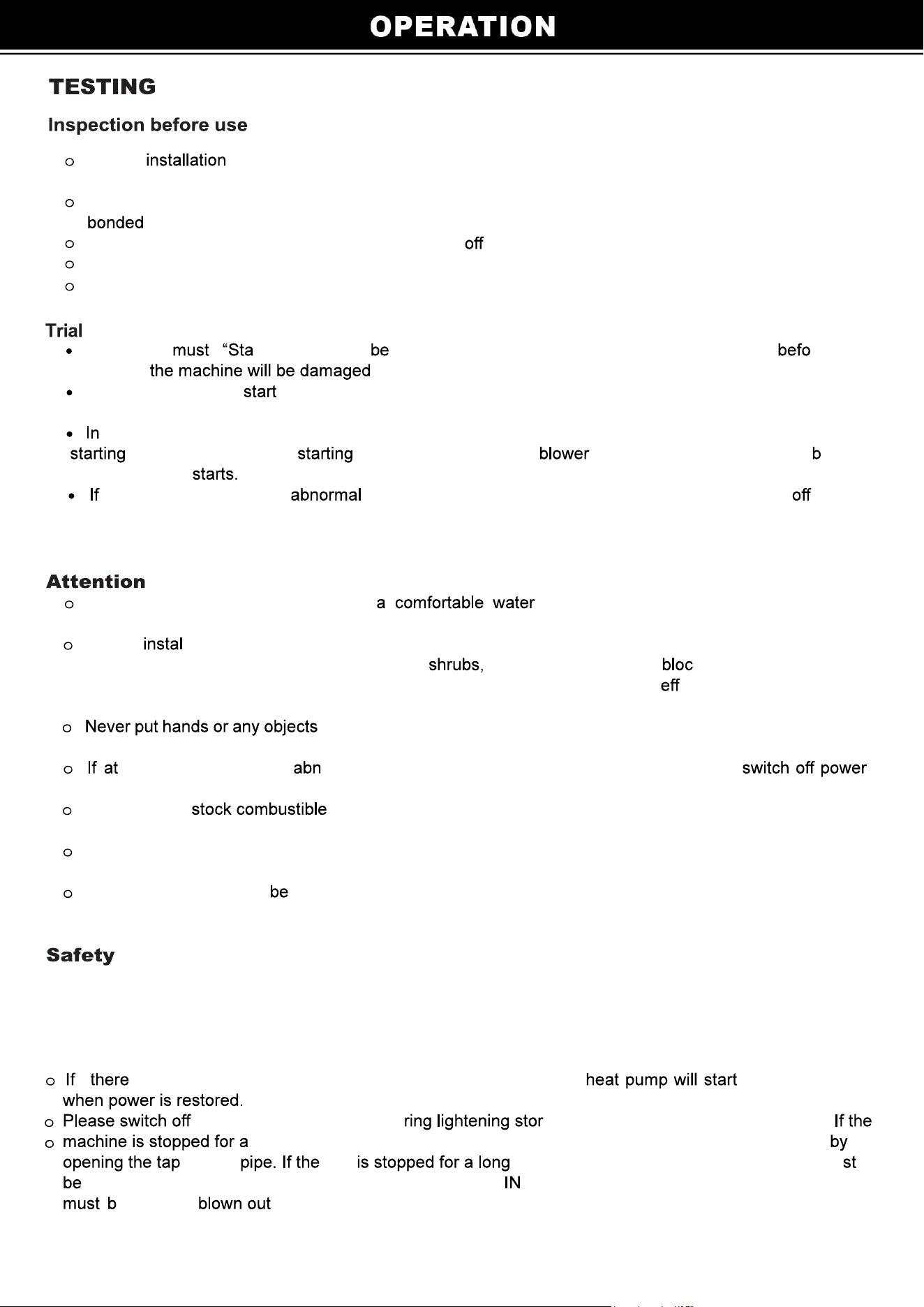
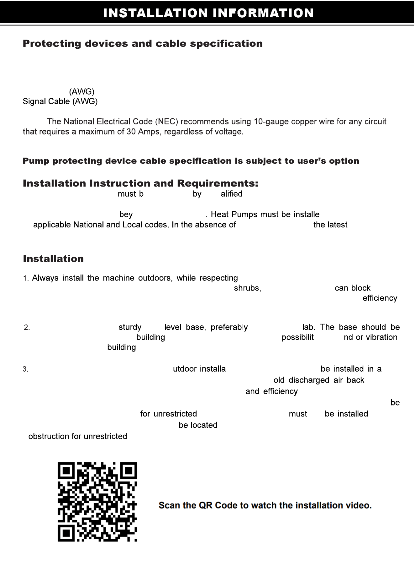
Check of the whole machine and the pipe connections according to the pipe
connection diagram
Check the electric wiring according to the electric wiring diagram; and make sure the Heat Pump is
Make sure that the main machine power switch is
Check the temperature setting.
Check the air inlet and outlet.
The user rt the Pump fore the Machine, And Turn off the Machine re the
Pump”, or
The user should the pump, check for any water leakage of water; set temperature
in the thermostat, and then switch on power supply.
order to protect the swimming pool heat pump, the machine is equipped with a time delay
function, whe n the machine, the will run for 3 minutes efore
the compressor
at any time there is an noise, smell, smoke, electricity leakage, plea se switch power
immediately and contact your local dealer.
Set temperature control to achieve temperature and to avoid overheating or
over cooling.
Always l the machine outdoors, while noting the minimal clearances needed forproper operation
and heating. DO NOT place the unit next to fences, etc.which can k the air inlet. These
locations deny the unit a continuous source of fresh air which reduces its iciency and may prevent
adequate heat delivery.
into outlet of the swimming pool heat pump, and don’t remove the screen
over the fan at any time.
any time there is an ormal noise, odor, smoke, electricity leakage, please
immediately and contact your local dealer.
Do not use or gas or liquids such as paint thinners, paint, fuel nearor around the
heat pump.
As with all pool heat pumps, you are advised to use a pool cover at night and when the pool is not in
use.
The heat pump should installed within 10m of the pool to minimize heat loss in the underground
pipes.
Please keep the main power supply switch out of reach from children.
is a power outage while the machine is in operation, the up automatically
the main power supply du ms to prevent anydamage to the unit.
long time, please cut off the power supply and drain water of the machine
of inlet unit period of time or for winterizing, the unit mu
drained of all its water. You will need to disconnect the and OUT water connections. Then the unit
e tilted or with air until all water is out.
10
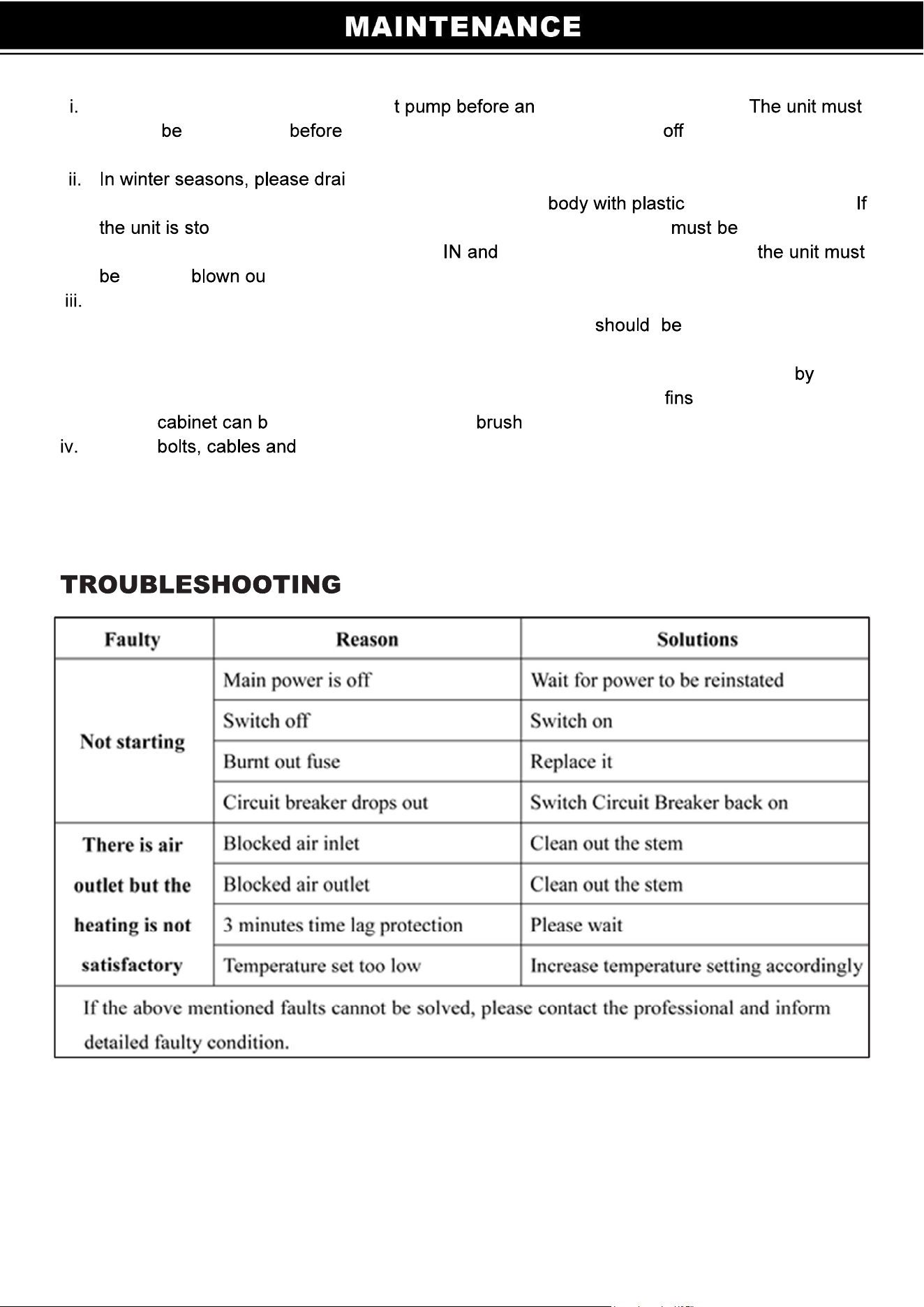
Disconnect power supply of the hea y examination and repair.
always powered off opening the access panel. Always cut the unit’s main power
whenever the access panel is open or removed.
n water clear of the machine, disconnect powe r Supply to
prevent any machine damage, and cover the machine cover to avoid dust.
pped for a long period of time or for winterizing, the unit drained of all
its water. You will need to disconnect the OUT water connections. Then
tilted or t with air until all water is out.
Please clean this machine with household detergents or clean water, NEVER gasoline,
thinners or any similar fuel. The area around the unit dry, clean and well
ventilated. Clean the side heating exchanger regularly to maintain good heat exchange and
conserve energy. Dirt can accumulate on the evaporator. You can easily remove it using
a non-pressured water spray without damaging the small aluminum . The cleaning of the
plastic e done with the help of a and soap.
Check connections regularly.
11
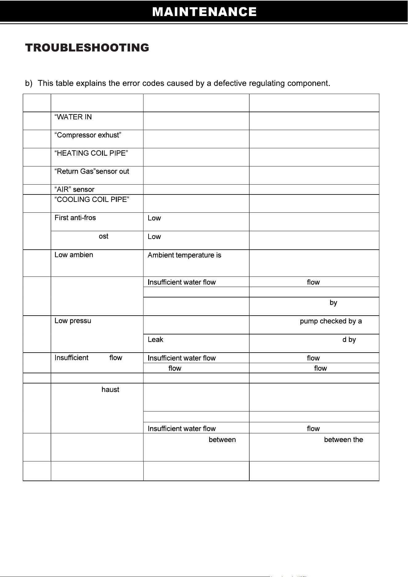
Displ
ay
Problem
Cause Solution
E20 ” sensor out of
order
Sensor open or short-circuited Check or replace the sensor
E10
sensor out of order
Sensor open or short-circuited Check or replace the sensor
E09
sensor out of order
Sensor open or short-circuited Check or replace the sensor
E12 of
order
Sensor open or short-circuited Check or replace the sensor
E04 out of order
Sensor open or short-circuited Check or replace the sensor
E25
sensor out of order
Sensor open or short-circuited Check or replace the sensor
E14 t protection
active
temperatures for water
and air
No action required
Second anti-fr
protection active
temperatures for water
and air
No action required
PP9 t temperature
protection
too
low or protection temperature
setting set too high
Check and repair.
E05 High pressure protection
Check the water
Pressure switch out of order Replace the pressure switch Have
Too much refrigerant gas
present
the heat pump checked a
refrigeration technician
E06 re protection
Not enough refrigerant gas Have the heat
refrigeration technician
in the cooling conduits Have the heat pump checke a
refrigeration technician
E03 water
Check the water
Water switch out of order Replace the Water switch
PEE Phase Protection
Faulty phase wiring Put phases in order
E07 compressor ex
temperature is too high
Water temperature and
environmental temperature is
too high
Set to the safety of water
temperature.
Refrigerant leakage Check and repair.
Check the water
E08
Communication failure
No communication
the digital display and the
system controller
Check the connection
screen and the controller.
Replace screen and/or controller.
PE2 Emergency switch
disconnect
Emergency switch disconnect Check and repair.
12
3
4