
Read all safety warnings and instructions. Failure to follow the warnings and instructions may result in
injury and/or property damage. Save all warnings and instructions for future reference. Read all safety
warnings and instructions. Failure to follow the warnings and instructions may result in injury and/or
property damage. Save all warnings and instructions for future reference.
SAVE THIS INSTRUCTION MANUAL
ATTENTION INSTALLER – THIS MANUAL CONTAINS IMPORTANT INFORMATION ABOUT THE
INSTALLATION, OPERATION, AND SAFE USE OF THIS PUMP THAT MUST BE FURNISHED TO
THE END USER OF THIS PRODUCT. FAILURE TO READ AND FOLLOW ALL INSTRUCTIONS
COULD RESULT IN SERIOUS INJURY.
WARNING – This product should be installed and serviced only by a qualified professional.
WARNING –
To reduce risk of injury, do not permit children to use or climb on this product. Closely
supervise children at all times. Pumps must be positioned to prevent children from using them as a
means of access to the pool.
CAUTION – Though this product is designed for outdoor use, it is strongly advised to protect the
electrical components from the weather. Select a well-drained area, one that will not flood when it rains.
It requires free circulation of air for cooling. Do not install in a damp or on ventilated location. If installed
within an outer enclosure or beneath the skirt of a hot tub or spa, adequate ventilation and free
circulation of air must be provided to prevent overheating of the motor.
WARNING – Pool and spa components have a finite life. All components should be inspected frequently
and replaced at least every ten years, or if found to be damaged, broken, cracked, missing, or not
securely attached.
WARNING – Risk of Electric Shock.
Hazardous voltage. Can shock, burn, or cause death. To reduce the risk of electric shock, do NOT use
an
1

extension cord to connect unit to electric supply. Provide a properly located outlet. It is required that
licensed electricians do all electrical wiring. All electrical wiring MUST be in conformance with applicable
local and national codes and regulations. Before working on pump or motor, disconnect motor wiring.
WARNING – To reduce the risk of electric shock, replace damaged cord immediately. DO NOT bury
cord. Locate cord to prevent abuse from lawn mowers, hedge trimmers and other equipment.
WARNING – Connect only to a grounding type receptacle protected by a Ground Fault Circuit
Interrupter (GFCI). Contact a licensed electrician if you cannot verify that the receptacle is protected by
GFCI.
WARNING – Failure to bond pump to pool structure will increase risk for electrocution and could
result in injury or death. To reduce the risk of electric shock, see installation instructions and consult a
professional electrician on how to bond pump. Also, contact a licensed electrician for information on local
electrical codes for bonding requirements.
Use a solid copper conductor, size 8 or larger. Run a continuous wire from external bonding lug to
reinforcing rod or mesh. Connect a No. 8 AWG (8.4 mm2) solid copper bonding wire to the pressure wire
connector provided on the motor housing and to all metal parts of swimming pool, spa, or hot tub, and to
all electrical equipment, metal piping (except gas piping), and conduit within 5 ft. (1.5m) of inside walls of
swimming pool, spa, or hot tub.
IMPORTANT - Reference NEC codes for all wiring standards including, but not limited to, grounding,
bonding and other general wiring procedures.
NOTE - The National Electrical Code (NEC) permits use of a cord with a maximum 3 ft. (1 m) length. If
your pump is equipped with a cord complying with the NEC, the preceding four (4) hazards apply.
WARNING – Suction Entrapment Hazard.
Suction in suction outlets and/or suction outlet covers, which are damaged, broken, cracked, missing, or
unsecured cause severe injury and/or death due to the following entrapment hazards:
Hair Entrapment- Hair can become entangled in suction outlet cover.
Limb Entrapment- A limb inserted into an opening of a suction outlet sump or suction outlet cover that is
damaged, broken, cracked, missing, or not securely attached can result in a mechanical bind or swelling
of the limb.
Body Suction Entrapment- A pressure applied to a large portion of the body or limbs can result in an
entrapment.
2

Evisceration/ Disembowelment- A negative pressure applied directly to the intestines through an unprotected
suction outlet sump or suction outlet cover which is damaged, broken, cracked, missing, or unsecured can result in
evisceration/disembowelment.
Mechanical Entrapment- There is potential for jewelry, swimsuits, hair decorations, fingers, toes, or knuckles to
be caught
in an opening of a suction outlet cover resulting in mechanical entrapment.
WARNING –
To Reduce the risk of Entrapment Hazards:
- When outlets are small enough to be blocked by a person, a minimum of two functioning suction outlets per pump
must be installed. Suction outlets in the same plane (i.e. floor or wall), must be installed a minimum of three feet
(3’) [0.91 meter] apart, as measured from near point to near point.
- Dual suction fittings shall be placed in such locations and distances to avoid “dual blockage” by a user.
- Dual suction fittings shall not be located on seating areas or on the backrest for such seating areas.
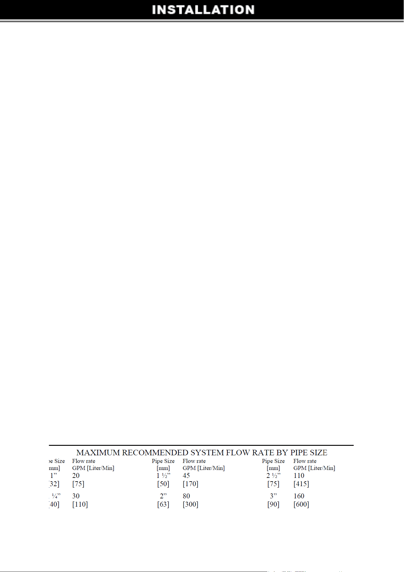
- The maximum system flow rate shall not exceed the values shown in the “Pipe Sizing Chart” found at
the bottom of page 4 of this manual.
- Never use pool or spa if any suction outlet component is damaged, broken, cracked, missing, or not
securely attached
- Replace damaged, broken, cracked, missing, or not securely attached suction outlet components
immediately.
- In addition to two or more suction outlets per pump installed in accordance with ASME, APSP
standards and CPSC guidelines, follow all national, state, and local codes applicable.
- Installation of a vacuum release or vent system, which relieves entrapping suction, is recommended.
WARNING – Hazardous Pressure.
Pool and spa water circulation systems operate under hazardous pressure during start-up, normal
operation, and after pump shut-off. Stand clear of circulation system equipment during pump start-up.
Failure to follow safety and operation instructions could result in violent separation of the pump housing
and cover due to pressure in the system, which could cause property damage, severe personal injury, or
death. Before servicing pool and spa water circulation system, all system and pump controls must be in
off position and filter manual air relief valve must be in open position. Before starting system pump, all
system valves must be set in a position to allow system water to return back to the pool. Do not change
filter control valve position while system pump is running. Before starting system pump, fully open filter
manual air relief valve. Do not close filter manual air relief valve until a steady stream of water (not air or
air and water) is discharged. All suction and discharge valves MUST be OPEN when starting the
circulation system.
3

Failure to do so could result in severe personal injury and/or property damage.
WARNING – Separation Hazard.
Failure to follow safety and operation instructions could result in violent separation of pump
components. Strainer cover must be properly secured to pump housing with strainer cover lock ring.
Before servicing pool and spa circulation system, all system and pump controls must be in off position
and filter manual air relief valve must be in open position. Do not operate pool and spa circulation
system if a system component is not assembled properly, damaged, or missing. Do not operate pool
and spa circulation system unless filter air relief valve body is in locked position in filter upper body. All
suction and discharge valves MUST be OPEN when starting the circulation system.
Failure to do so could result in severe personal injury and/or property damage.
WARNING – Never operate or test the circulation system at more than 40 PSI.
WARNING – Fire and burn hazard.
Motors operate at high temperatures and if they are not properly isolated from any flammable structures
or foreign debris they can cause fires, which may cause severe personal injury or death. It is also
necessary to allow the motor to cool for at least 20 minutes prior to maintenance to minimize the risk for
burns.
WARNING – Failure to install according to defined instructions may result in severe personal injury
or death.
4
5
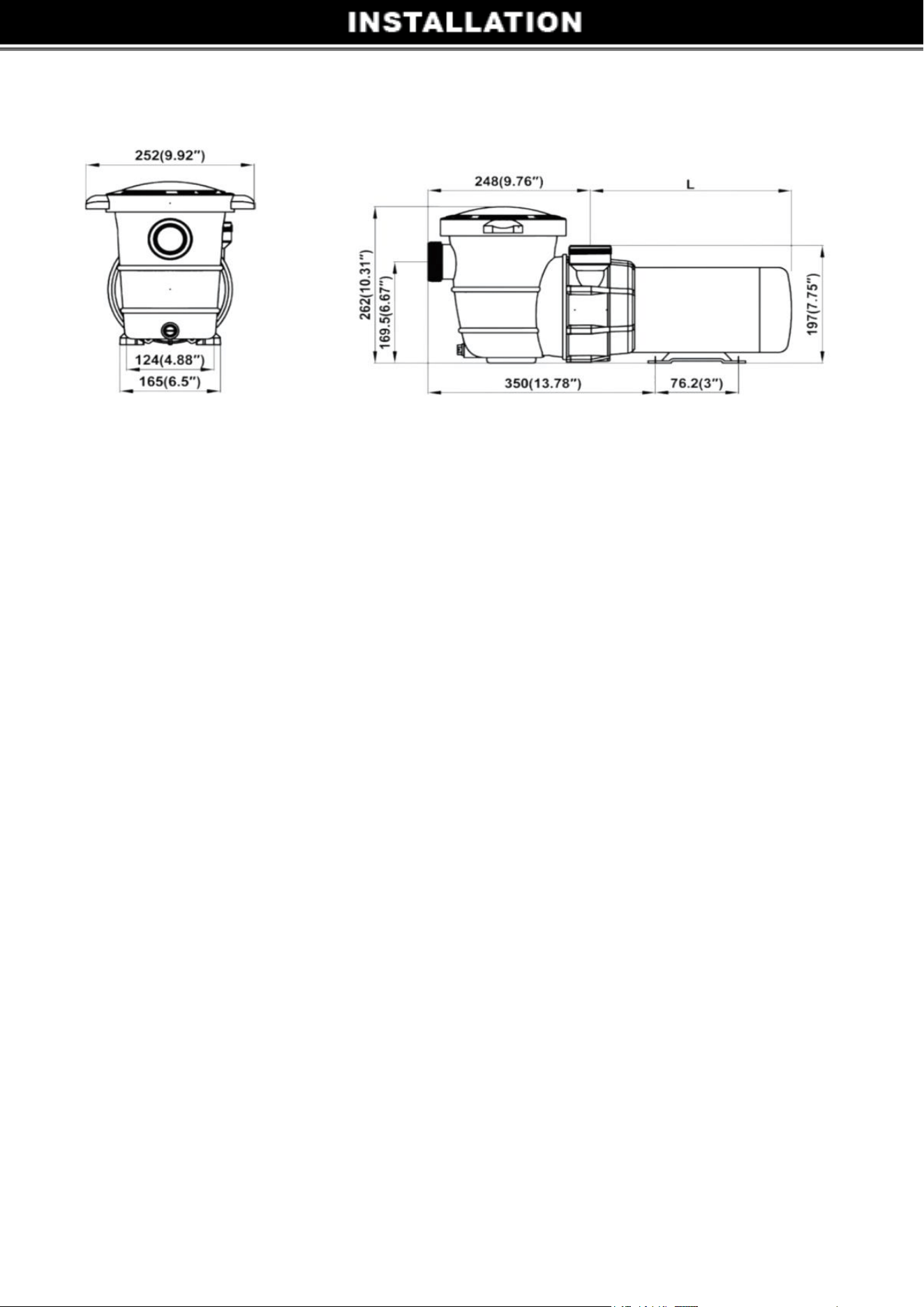
Dimensions
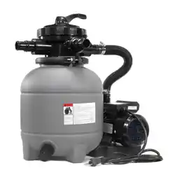
Pump Location
Locate pump as close to pool as practical and run suction lines as direct as possible to reduce friction
loss. Suction lines should have continuous slope upward from lowest point in line. Joints must be tight
(but not over-tightened). Suction line diameter must equal or be larger than the discharge line
diameter. Locate pump below pool water line will gain a best performance.
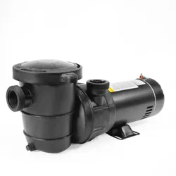
Pump Mounting
Install pump on a firm, level base or pad to meet all local and national codes. Fasten pump to base or
pad with screws or bolts to further reduce vibration and stress on pipe or hose joints. The base MUST
be solid, level, rigid, and vibration free.
Pump mount must:
Allow pump inlet height to be as close to water level as possible.
Item No.
• Allow use of short, direct suction pipe (to reduce friction losses).
• Allow for gate valves in suction and discharge piping.
• Be protected from excess moisture and flooding.
• Allow adequate access for servicing pump and piping.
6
Pipe Sizing Chart
NOTE - It is recommended that a minimum length of piping, equivalent to 10 pipe diameters, be used
between the pump suction inlet and any plumbing fittings.
WARNING – Hazardous Pressure.
Pumps, filters, and other equipment/ components of a swimming pool filtration system operate under
pressure. Incorrectly installed and/or improperly tested filtration equipment and/or components may fail
resulting in injury and/or property damage.
Plumbing
Use Teflon tape to seal threaded connections on molded plastic components. All plastic fittings must
be new or thoroughly cleaned before use. NOTE - Do NOT use Plumber’s Pipe Dope as it may
cause cracking of the plastic components. When applying Teflon tape to plastic threads, wrap the
entire threaded portion of the male fitting with one to two layers of tape. Wind the tape clockwise as
you face the open end of the fitting, beginning at the end of the fitting. The pump suction and outlet
ports have molded-in thread stops. Do NOT attempt to force hose connector fitting past this stop.
It is only necessary to tighten fittings enough to prevent leakage. Tighten fitting by hand and then use a
tool to engage fitting an additional 1 ½ turns. Use care when using Teflon tape as friction is reduced
considerably; do NOT over-tighten fitting or you may cause damage. If leaks occur, remove
connector, clean off old Teflon tape, re-wrap with one to two additional layers of Teflon tape, and re-
install connector.
Fittings

7
Fittings restrict flow. For better efficiency, use the fewest possible fittings (but at least two suction
outlets). Avoid fittings that could cause an air trap. Pool and spa fittings MUST conform to the
International Association of Plumbing and Mechanical Officials (IAPMO) standards. Use a non-
entrapping suction fitting in pool (multiple drains) or double suction (skimmer and main drain).
Electrical
WARNING – Ground and bond motor before connecting to electrical power supply. Failure to ground
and bond pump motor can cause serious or fatal electrical shock hazard.
WARNING – Do NOT ground to a gas supply line.
WARNING – To avoid dangerous or fatal electrical shock, turn OFF power to motor before working on
electrical connections.
WARNING – Ground Fault Circuit Interrupter (GFCI) tripping indicates electrical problem. If GFCI trips
and won’t reset, consult electrician to inspect and repair electrical system.
WARNING – Fire Hazard.
Match supply voltage to motor nameplate voltage.
Ensure that the electrical supply available agrees with the motor’s voltage, phase, and cycle, and that
the wire size is adequate for the H.P. (KW) rating and distance from the power source. NOTE - All
electrical wiring MUST be performed by a licensed electrician, and MUST conform to local codes
and NEC regulations. Use copper conductors only.
60Hz, 1 PH
HP
KW
Voltage
Amps
Wire Size
1/2
0.38
115
7.3
14 AWG
3/4
0.50
115
9.2
14 AWG
1
0.75
115
12
14 AWG
1-1/2
1.15
115
15
14 AWG
8
Voltage
Voltage at motor MUST NOT be more than 10% above or below motor name plate rated voltage, or
motor may overheat, causing overload tripping and reduced component life. If voltage is less than 90%
or more than 110% of rated voltage when motor is running at full load, consult Power Company.
Grounding And Bonding
Install, ground, bond, and wire motor in accordance with local or national electrical code requirements.
Permanently ground motor. Use green ground terminal provided under motor canopy or access
place; use size and type wire required by code. Connect motor ground terminal to electrical service
ground. Bond motor to pool structure. Bonding will connect all metal parts within and around the pool
with a continuous wire.
Bonding reduces the risk of a current passing between bonded metal objects, which could potentially
cause electrical shock if grounded or shorted. Reference NEC codes for all wiring standards
including, but not limited to, grounding, bonding and general wiring procedures.
Use a solid copper conductor, size 8 or larger. Run wire from external bonding lug to reinforcing rod or
mesh. Connect a No. 8 AWG (8.4 mm2) solid copper bonding wire to the pressure wire connector
provided on the motor housing and to all metal parts of swimming pool, spa, or hot tub, and to all
electrical equipment, metal piping (except gas piping), and conduit within 5 ft. (1.5 m) of inside walls of
swimming pool, spa, or hot tub.
Wiring
If other lights or appliances are also on the same circuit, be sure to add their amp loads before figuring
wire and circuit breaker sizes. (NOTE: If unsure how to do this or if this is confusing, consult a licensed
electrician). Use the load circuit breaker as the Master On-Off switch. NOTE: If you do not use conduit
when wiring motor, be sure to seal wire opening on end of motor to prevent dirt, bugs, etc., from
entering.
Start-Up & Operation
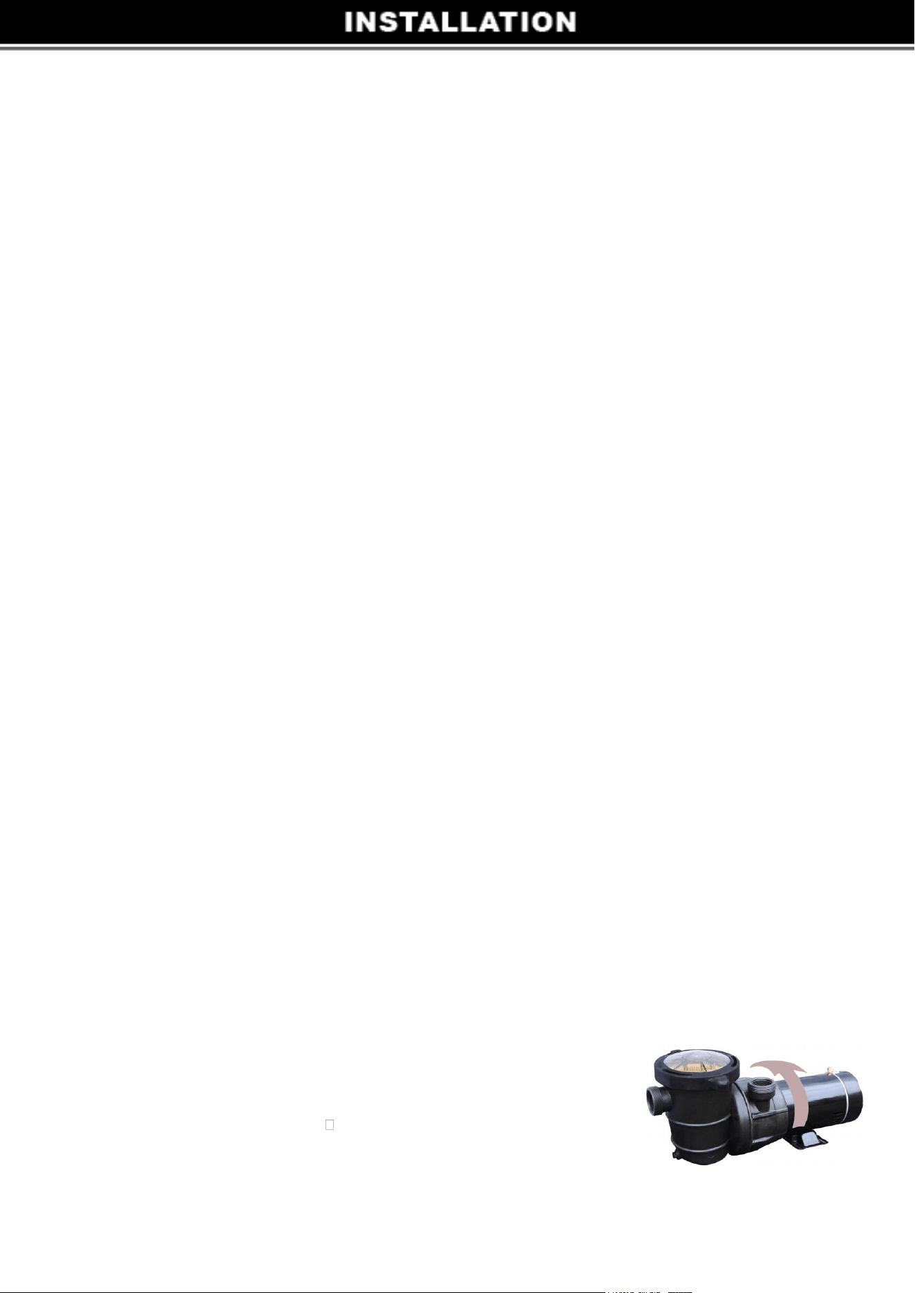
Selecting Pump’s Discharge Position (4 Steps)
This pump can be easily positioned for horizontal or vertical water discharge.
Step 1: Remove ALL plumbing attached to pump.
Step 2: Remove strainer housing.

⚫ Disengage and lift off strainer cover.
⚫ Remove strainer basket.
⚫ Lift up on strainer ‘C’ clip (JR03703004 in parts listing on Page13 ) and remove.
⚫ Slide strainer housing forward and remove.
Step 3: Press positioning button located on pump housing and rotate discharge port to desired position.
NOTE: Discharge port will only rotate ¼ turn.
Step 4: Assemble the pump by following the above directions in the reverse manner.
Prior to Start-Up
Fill strainer housing with water to suction pipe level. NEVER OPERATE THE PUMP WITHOUT WATER.
Water acts as a coolant and lubricant for the mechanical shaft seal.
Notice: If it is necessary to perform a pressure test, prior to initial use to ensure pump is functioning
properly, then the following criteria should be maintained for this test:
1. Have a professional perform this test.
2. Ensure all pump and system components are sealed properly to prevent leaks.
3. Remove any trapped air in the system by fully opening filter manual air relief valve until a steady stream
of water is discharged.
4. Allow no more than 40 psi (276 kPa) at a water temperature no higher than 100° F (38° C).
5. Run pressure test for no longer than 24 hours. Immediately inspect all parts to verify they are intact and
functioning properly.
WARNING – If pump is being pressure tested (40 PSI MAXIMUM), be sure pressure has been released
before removing strainer cover.
CAUTION – NEVER run pump dry. Running pump dry may damage seals, causing leakage, flooding, and
voids warranty. Fill strainer housing with water before starting motor.
ATTENTION – DO NOT add chemicals to pool/spa system directly in front of pump suction.
9

10
ATTENTION – Before removing strainer cover:
1. STOP PUMP before proceeding.
2. CLOSE VALVES in suction and outlet pipes.
3. RELEASE ALL PRESSURE from pump and piping system.
Priming Pump
CAUTION – All suction and discharge valves MUST be OPEN, as well as filter air relief valve (if
available) on filter, when starting the circulating pump system. Failure to do so could result in severe
personal injury.
Release all pressure from filter, pump, and piping system. If water source is higher than the pump,
pump will prime itself when suction and outlet valves are opened. If water source is lower than the
pump, unscrew and remove strainer cover; fill strainer housing with water. Turn clockwise to tighten
strainer cover.
NOTE - Tighten strainer cover by hand only (no wrenches).
Turn on power and wait for pump to prime, which may take up to five (5) minutes. Priming time will
depend on vertical length of suction lift and horizontal length of suction pipe. If pump does NOT prime
within five minutes, stop motor and determine cause. Be sure all suction and discharge valves are open
when pump is running. See Troubleshooting Guide.
ATTENTION – Wait five (5) seconds before re-starting pump. Failure to do so may cause reverse
rotation of motor and consequent serious pump damage. Close filter manual air relief valve after pump is
primed.

• Clean strainer basket regularly. Do NOT strike basket to clean. Inspect strainer cover
gasket regularly and replace as necessary. Pumps have self-lubricating motor bearings and
shaft seals. No lubrication needed.
Keep motor clean. Insure air vents are free from obstruction to avoid damage. Do NOT use
water to hose off motor.
Occasionally, shaft seals must be replaced, due to wear or damage. Replace with genuine
seal assembly kit. See “Shaft Seal Change Instructions” in this manual.
Storage
WARNING – Separation Hazard.
Do not purge the system with compressed air. Purging the system with compressed air can
cause components to explode, with risk of severe injury or death to anyone nearby. Use
only a low pressure (below 5 PSI), high volume blower when air purging the pump, filter, or
piping.
ATTENTION – Allowing the pump to freeze will void the warranty.
ATTENTION – Use ONLY propylene glycol as antifreeze in your pool/spa system.
Propylene glycol is
nontoxic and will not damage plastic system components; other anti-freezes are highly
toxic and may damage plastic components in the system.
Drain all water from pump and piping when expecting freezing temperatures or when
storing pump for a long time (see instructions below).
Keep motor dry and covered during storage. To avoid condensation/corrosion problems,
do NOT cover or wrap pump with plastic film or bags.
Winterization
11

Shaft Seal Change Instructions
IMPORTANT SAFETY INSTRUCTIONS
PLEASE READ AND FOLLOW ALL INSTRUCTIONS
When servicing electrical equipment, basic safety precautions should always be
observed including the following. Failure to follow instructions may result in injury.
ATTENTION
A. Disconnect all electrical power service to pump before beginning shaft seal
replacement.
B. Only qualified personnel should attempt rotary seal replacement. Contact your local
authorized Dealer or service center if you have any questions.
C. Exercise extreme care in handling both the rotating and the stationary sections of the
two-part replacement seal. Foreign matter or improper handling will easily scratch the
graphite and ceramic sealing surfaces.
Follow instructions
1. Remove the strainer by disengaging and removing the strainer cover. Remove the
basket. Lift up on strainer ‘C’ clip and remove. Finally, slide strainer housing forward and
remove.
2. Unscrew eight (8) screws and remove pump cover, exposing the impeller.
3. Remove the canopy or the shaft cover plate from the end of motor opposite the
impeller.
4. Hold the motor shaft securely by either inserting a screwdriver in slot at end of shaft or
by using an open-end wrench to engage the flat surfaces provided near end of motor
shaft. Rotate the impeller in a counterclockwise direction and remove it from the motor
shaft.
5. Note how the steel spring section of the old seal is positioned on impeller hub and
remove it by pulling from the impeller.
6. Loosen four (4) motor through bolts from the back of motor and remove pump
housing/shroud from the front of the motor.
7. Remove the ceramic stationary portion of the old seal by pressing the white ceramic
seat out of the pump housing recess. If assembly is tight, tap lightly from the “motor”
side.
8. Clean and lubricate the impeller stem and the pump housing recess with a dilute
solution of non-granulated liquidtype soap. Do not use petroleum or silicone lubricants as
these can contribute to seal leakage.
12

Seal Replacement
13
9. Press the new rotating portion of the seal assembly onto the impeller stem with the polished black
graphite surface facing away from the impeller.
10. Carefully press the stationary ceramic portion of the seal into the recess of the pump housing/
shroud, with the polished flat surface facing out.
11. Carefully insert the motor shaft through the pump housing/shroud and align with white ceramic
stationary seal assembly in place and secure the motor to pump housing/shroud with four (4) motor
through bolts removed in step #7. Be sure motor base and pump discharge port are positioned
properly. Alternately tighten the motor through bolts until the pump housing is secure. Make certain
motor shaft turns freely before proceeding.
12. Screw the impeller (clockwise) with the rotating portion of seal in place onto the motor shaft. Hand-
tighten the impeller in place.
13. Clean (replace if necessary) the O-ring and replace on pump cover. Assemble the pump cover to
the pump housing/ shroud with the eight (8) screws removed in step #3. Tighten screws alternately
and evenly.
14. Re-assemble strainer by sliding strainer housing onto pump cover. Install strainer ‘C’ clip by
pushing clip down onto grooved pump cover coupling. Insert basket and fasten strainer cover.

14
ISSUE POSSIBLE SOLUTION
MOTOR WILL NOT START
Improper or loose wiring connections; open switches or relays; tripped circuit breakers, GFCI’s, or blown fuses.
Manually check rotation of motor shaft for free movement and lack of obstruction.
If you have a timer, be certain it is working properly. Bypass it if necessary.
MOTOR SHUTS OFF
Undersized wiring; loose connections; etc.
Low voltage at motor or power drop (frequently caused by undersized wiring or extension cord use).
Mechanical binding and electrical overload.
MOTOR HUMS BUT DOES
NOT START
Centrifugal switch stuck in OPEN position.
Binding of motor shaft.
PUMP WON’T PRIME
Make sure pump/strainer housing is filled with water and the cover O-ring is clean, also be sure it is properly seated in
the cover O-ring groove. Make sure strainer cover is locked firmly in position and lubricated with “Jack’s 327”.
Make sure all suction and discharge valves are fully open and not blocked, that pool water level is at
proper level, and that skimmer weir is not hung up or stuck on skimmer wall.
Block off to determine if pump will develop a vacuum. You should have 5”-6” of vacuum at the strainer
cover. You may be able to check by removing the skimmer basket and holding your hand over the bottom
port with skimmer full and pump running. If no suction if felt, check for line blockage.
A. If pump develops a
vacuum, check for blocked suction line or dirty strainer basket, and air leak in the
suction piping may be the cause.
b. If pump does not develop a vacuum and pump has sufficient “priming water”:
i.
Re-check strainer housing cover and all threaded connections for suction leaks. Check if all hose clamps are tight.
ii.Check voltage to ensure that the motor is rotating at full RPM’s.
iii. Open housing cover and check clogging or obstruction in suction. Check impeller for debris. iv.
Remove and replace shaft seal only if it is leaking.
LOW FLOW
Clogged or restricted strainer or suction line; undersized pool piping.
Plugged or restricted discharge line or filter, valve partially closed (high gauge reading). How to correct:
Sand filters - backwash as per manufacturer’s instructions; D.E. filters - backwash as per manufacturer’s
instructions; Cartridge filters - clean or replace cartridge.
NOISY PUMP
Vibration due to improper mounting, etc. Put a rubber pad under metal mounting feet.
Foreign matter in pump housing. Loose stones/debris hitting impeller could be cause, remove any of the above.
Motor bearings noisy from normal wear, rust, overheating, or concentration of chemicals causing seal
damage which will allow chlorinated water to seep into bearings wiping out the grease causing bearing to
whine. All seal leaks should be replaced at once.
15
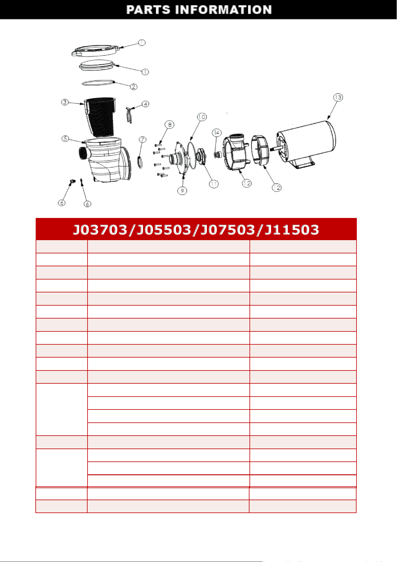
J03703/J05503/J07503/J11503
No. Description Item#
1 Lid & Clamp Ring JR05501001
2 O-Ring JR05501002
3 Basket JR05501003
4 Clip-bayonet JR03703004
5 Strainer Casing JR03703005
6 Drain Plug JR03703006
7 Diffuser O-Ring JR03703007
8 Screw JR03703008
9 Diffuser JR03703009
10 Pump Housing O-Ring JR03703010
11
Impeller for J03703 JR03703011
Impeller for J05503 JR05503011
Impeller for J07503 JR07503011
Impeller for J11503 JR11503011
12 Pump Housing JR03703012
13
Motor for J03703 JM03703
Motor for J05503 JM05503
Motor for J07503 JM07503
Motor for J11503
JM
11503
14 Shaft Seal JR05501014
16