INGROUND POOL PUMP 1.5 HP
230V 2-SPEED
SKU: 75406
INSTALLATION AND
USER’S GUIDE
75406
Read all safety warnings and instructions.
Failure to follow the warnings and
instructions may result in electric shock,
fire and/or serious injury. Save all warnings
and instructions for future reference.
DANGER

THIS PAGE INTENTIONALLY LEFT BLANK

CUSTOMER SERVICE
If you have any questions about ordering our pool pumps and replacement parts or pool products, please feel
free to contact us using the following contact information:
Customer Service and Technical Support
Phone: (909) 628-0880
Email: [email protected]
Hours of Operation: Monday – Friday, 9AM – 4PM (CST)
TABLE OF CONTENTS
CUSTOMER SERVICE
Customer Service and Technical Support
IMPORTANT SAFETY INSTRUCTIONS
Legends and Symbols
GENERAL SAFETY
INSTALLATION
INSPECTION
IMPORTANT SAFETY INSTRUCTION
INSTALLATION LOCATION
PUMP PLUMBING
ELECTRIAL DATA
OPERATION
PUMP START UP
WINTERIZING
TROUBLESHOOTING
REPLACEMENT PARTS
DISCLAIMER
Parts Diagram
TABLE OF CONTENTS
For Solvent Weld Connection
For Theraded Connection
Controling the Output
PUMP MAINTENANCE
CLEANING
1
1
1
2
2
3
6
6
6
6
7
7
7
7
7
8
8
8
8
8
8
9
9
9
10
14
14
15
GENERAL PLUMBING
SERVICE & REPAIR PARTS
WATER CHEMISTRY
SPECIFICATIONS
2
IMPORTANT SAFETY INSTRUCTIONS
For safety reasons, children should not be allowed to use this product.
Failure to comply with all instructions and warnings may lead to severe bodily injury or even
death. This pump must be installed and serviced exclusively by a qualified pool service professional. Prior to
using this pump, installers, pool operators, and owners must carefully review these warnings and all
instructions provided in the owner's manual. It is essential to leave these warnings and the owner's manual
with the pool owner for their reference and safety.
ATTENTION INSTALLER: This manual contains vital information regarding the installation, operation, and
safe use of this variable speed pump. It is essential to provide this manual to the end user of the product.
Failure to read and follow all instructions could lead to severe injuries.
USE OF NON-XTREMEPOWERUS REPLACEMENT PARTS VOIDS WARRANTY
DANGER: Ignoring these hazards can result in death, severe personal injury, or significant
property damage.
WARNING: Indicates potential hazards that can result in severe personal injury, death, or
significant property damage. Ignoring these warnings presents a real danger.
CAUTION: Indicates potential hazards that can result in minor or moderate personal injury,
property damage, or actions that are unpredictable and unsafe. Ignoring these cautions
presents a potential hazard.
NOTICE: This label indicates important special instructions that are not directly related to
hazards.
This guide provides instructions for installing and using the pump. If you have any questions about the
equipment, please contact XtremepowerUS.
This guide contains important information about safely installing and operating this product. After installation,
make sure to share this information with the owner/operator or leave it with them for their reference.
Legends and Symbols
When you come across the safety-alert symbol on your equipment or in this manual, pay attention to the
following signal words and remain vigilant about the potential for personal injury.
IMPORTANT SAFETY INSTRUCTIONS
DANGER
WARNING
WARNING
CAUTION
NOTE
DANGER

3
IMPORTANT SAFETY INSTRUCTIONS
This pump is specifically designed for use with permanent swimming pools and, if
appropriately marked, can also be used with hot tubs and spas. However, it should not be used with storable
pools. A permanently installed pool is one that is built in or on the ground, or within a building, making it
incapable of being easily disassembled for storage. On the other hand, a storable pool is designed to be
disassembled and reassembled for storage while maintaining its original integrity. Please ensure that this
pump is only used with permanent swimming pools and hot tubs or spas if appropriately indicated. Avoid using
it with storable pools to prevent potential hazards and ensure optimal performance.
Please note that this unit must only be connected to a supply circuit protected by a
ground-fault circuit-interrupter (GFCI). The installation of a GFCI is the responsibility of the installer, and it
should be regularly tested for proper functioning. To test the GFCI breaker, simply press the test button, which
should interrupt power. Pressing the reset button should restore power. If the GFCI fails to operate as
described, it is defective and should be replaced. If the GFCI interrupts power to the pump without pressing
the test button, it indicates the presence of a ground current and the possibility of electric shock. In such
cases, do not use the pump. Disconnect it immediately and seek the expertise of a qualified service
representative to address and rectify the issue before resuming use (to test the GFCI breaker).
Risk of electrical shock. Connect this product solely to a branch circuit that is safeguarded
by a ground-fault circuit interrupter (GFCI). If you are unable to confirm the presence of a GFCI protection on
the circuit, please seek assistance from a qualified electrician.
DANGER
WARNING
WARNING

4
IMPORTANT SAFETY INSTRUCTIONS
During installation, ensure proper drainage around the pump to prevent water from entering the
electrical components.
Please note that these instructions cover a range of pump models, and as a result, some instructions
may not be applicable to a specific model. Nevertheless, all models are designed specifically for use in
swimming pool applications.
To ensure optimal performance, it is crucial to use the proper size pump for the specific application and
install it correctly. Only through meticulous sizing and installation can the pump function as intended.
The use of pumps that are improperly sized, installed, or employed for applications other than their
intended purpose can lead to severe personal injury or even death. These risks encompass potential
hazards such as electric shock, fire, flooding, suction entrapment, or critical injuries and property
damage resulting from structural failures of the pump or other system components. It is essential to
strictly adhere to the correct sizing, installation, and designated usage to mitigate these potential
dangers and ensure the safety of all users and the surrounding environment.
It is imperative that all work related to the pump is carried out exclusively by a qualified
service professional, ensuring full compliance with all relevant national, state, and local codes.
The pump is not designed to be submersible.
Never open the inside of the drive or motor enclosure as there is a capacitor bank that retains a 230
VAC charge even when the unit is not powered.
Prior to servicing the pump, switch OFF the power by disconnecting the main circuit to the pump.
Exercise caution when installing and programming the pump to limit its performance potential when
using old or questionable equipment due to its high flow rates.
Note that electrical connection requirements may vary from country to country, state to state, and local
municipalities. Install the equipment following the National Electrical Code and all relevant local codes
and ordinances.
This appliance is not intended for use by individuals (including children) with reduced physical, sensory,
or mental capabilities, or those lacking experience and knowledge.
GENERAL SAFETY
WARNING
WARNING
5
IMPORTANT SAFETY INSTRUCTIONS
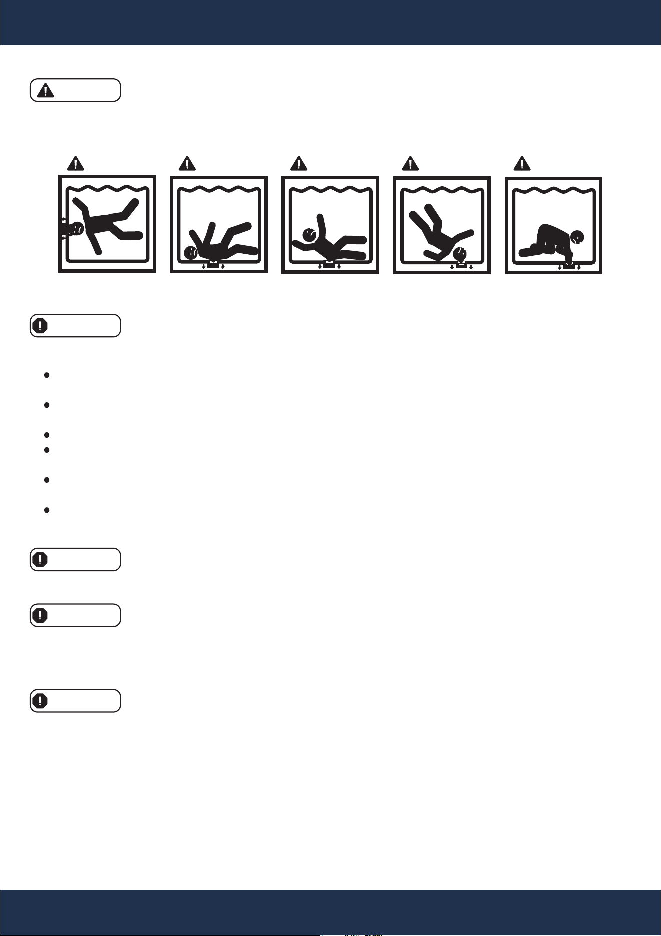
SUCTION ENTRAPMENT HAZARD
DANGER DANGER DANGER DANGER DANGER
An emergency shut-off switch for the pump must be prominently labeled and placed in a
location that is easy to access and readily apparent. It is crucial to ensure that all users are familiar with the
switch's location and understand how to use it effectively in case of an emergency. This measure ensures swift
and safe response to any critical situations that may arise during the pump's operation.
To ensure safety, it is of utmost importance that the suction plumbing is installed in strict
accordance with the most recent national and local codes governing swimming pools. By adhering to these
codes and regulations, we can significantly minimize the hazards associated with the pump's suction and
create a secure environment for all pool users.
By adhering to these precautionary measures, you can significantly reduce the risk of injury
associated with suction entrapment hazards.
Use only properly installed and secured ANSI/ASME A112.19.8 approved anti-entrapment suction
covers for each drain.
Ensure that each suction cover is installed at least three (3') feet apart, measured from the nearest point
to nearest point.
Regularly check all suction covers for cracks, damage, and excessive weathering.
Promptly replace any loose, cracked, damaged, broken, or missing cover with an appropriate certified
one.
Periodically replace drain covers as necessary since they deteriorate over time due to exposure to
sunlight and weather.
Avoid placing hair, limbs, or your body near any suction cover, pool drain, or outlet.
To minimize the risk of injury caused by suction entrapment hazards, please follow these
safety guidelines:
The pump has the potential to generate significant levels of suction within the plumbing
system's suction side. This heightened suction presents a considerable risk if individuals come too close to
the suction openings. Being near these openings can result in severe injuries caused by the intense vacuum
or may lead to entrapment and drowning.
DANGER
WARNING
WARNING
WARNING
WARNING

6
INSTALLATION
Examine the equipment when received. Notify your dealer or carrier of any damage or missing parts. Verify
that equipment is of size and model specified.
Inspection
When installing and using this electrical equipment,basic safety precations should always be followed,
including the following:
Important Safety Instructions
1. READ AND FOLLOW ALL INSTRUCTIONS.
2. WARNING - To reduce risk of injury, do not permit children to use this product unless they are closely
supervised at all times.
3. WARNING - (For cord & plug connected units). Risk of Electrical Shock. Connect only to a grounding type
receptacle protected by a ground-fault circuit-interrupter (GFCI). Contact a qualified electrician if you
cannot verify that the receptacle is protected by a GFCI.
4. WARNING - (For cord & plug connected units). Do not bury cord. Locate cord to minimize abuse from lawn
mowers, hedge trimmers and other equipment.
5. WARNING - (For cord & plug connected units). To reduce the risk of electric shock, replace damaged cord
immediately.
6. WARNING - (For cord & plug connected units). To reduce the risk of electrical shock do not use an
extension cord to connect unit to electrical supply; provide a properly located outlet.
7. CAUTION - (For pumps with a 25 ft. (7.62m cord). This pump is for use with storable pools only. Do not
use with permanently installed pools. A storable pool is constructed so that it may be readily disassembled
for storage and reassembled to its original integrity. A permanently installed pool is constructed in or on the
ground or in a building such that it cannot be readily disassembled for storage.
8. CAUTION - (For pumps with/without 3ft.(91m cord) or 6ft.(1.82m cord). This pump is for use with
permanently installed pools and may also be used with hot tubs and spas if so marked. Do not use with
storable pools. A permanently installed pool is constructed in or on the ground or in a building such that it
cannot be readily disassembled for storage. A storable pool is constructed so that it may be readily
disassembled for storage and reassembled to its original integrity.
9. WARNING - (For hot tub and spa pumps). Do not install within an outer enclosure or beneath the skirt of
the hot tub or spa, unless so marked.
10. SAVE THESE INSTRUCTIONS!
Locate pump as close to pool/spa as possible, preferably in a dry, well ventilated area away from direct
sunlight. It should be on a hard, level surface. Give consideration to:
Installation Location
1. Drainage - away from pump.
2. Ventilation of pump motor.
3. Access for future servicing and winterizing.
4. Protection from the elements.
Pumps without strainer bodies are designed for flooded suction {all suction fittings and suction piping below
water level) and will not self-prime. Consequently, the pump must be installed at an elevation that is below
water level when pool or spa is filled; however, if suction line valves are installed, the pump may be closed for
priming. Keep vertical distance to a minimum if you choose to mount pump above water level.
Pumps with strainer bodies are self-priming but should be mounted as close to the water level as possible or
below for ease in priming.

7
INSTALLATION
FOR SOLVENT WELD CONNECTION
General Plumbing
Rigid or flexible PVC pipe can be used. Pipe ends should be clean and free of any flash cause by the cutting
operation. Be sure that the proper adhesive is used on the type of pipe specified.
NOTE
A primer will assure that adhesive joints are superior. Suregard P-3000 has a purple tracer
to qualify in areas where codes specify a primer must be used.
CAUTION
We recommend that you consider climatic conditions when applying adhesives. Certain
atmospheric situations, such as high moisture content, make adhesive action of certain glues less effective.
Check the manufacturer's instructions.
FOR THREADED CONNECTIONS
Rigid or flexible PVC pipe can be used. Pipe ends should be clean and free of any flash cause by the cutting
operation. Be sure that the proper adhesive is used on the type of pipe specified.
Pump Plumbing
Suction pipe should be as large or larger that discharge pipe. Avoid using suction pipe small that pump
connection.
Keep the piping as straight and short as possible, and of suitable size. Avoid connecting an elbow directly into
the pump inlet (use a length of straight pipe to allow a proper entry for the water). Arrange horizontal runs to
slope upward to the pump to prevent high spots that could form air pockets. Support the pipe independently
so that it places no strain on the pump. Keep as much of the suction line as possible below the water level to
reduce priming time. Install valves and unions in the pump suction and return lines to facilitate servicing.
Valves are recommended for throttling
maintenance if the system is installed below deck level. Suction valves are essential for priming all pumps
without strainer bodies installed above water level. Pumps with
strainer bodies are self-priming, nevertheless, we recommend the use of check valve in the suction pipe at or
below the water level if the suction lift is more that five feet or if the dry suction is more that ten feet long. Keep
the valve in the suction line fully open during operation.
Electrical Data
Refer to information on motor nameplate fo electrical service data. All motors should have fused disconnect
switch or circuit breaker. Be sure wire size is sufficient for pump HP and distance from power source. Wiring
should be done in accordance with applicable codes by a competent electrician.
We recommend the installation of a ground fault circuit interrupter for maximum safety.

8
OPERATION
Pump Start Up
Do not operate pump until it has been primed as water acts to cool and lubricate the seal. For pumps without
strainer bodies and locater above water, close suction line valve and fill pump with water in order to prime. For
pumps with strainer bodies and located above water, prime by removing strainer cover and filling strainer body
with water. Pumps located below water level will selfprime if all piping is also below water level. After pump
has been
primed, energize motor and open all suction and discharge line valves. It may take some time for pump to
remove air from suction lines. If no flow is observed in five minutes, stop the motor and re-prime. If the pump
fails to operate, check for air leaks. Refer to Trouble Shooting section.
After about ten minutes of operation, check the return fittings for air bubbles. A continuous flow of air indicates
leaks in suction line. Locate and correct any leaks immediately.
CONTROLLING THE OUTPUT
Keep the gate valve in the suction line fully open during operation. Should it be necessary to control the
output, use a valve in the return line.
CAUTION
Do not retighten strainer Ring-Lok during operation.
CAUTION
Do not operate pump with closed suction or discharge valves.
Winterizing
Consult your dealer for advice on winterizing your equipment if freezing temperatures occur in your locality.
His knowledge of your equipment makes him the best qualified source of information. Follow his
recommendations, and if these include draining the filter system, proceed as follows:
1. If your system does not contain a filter, proceed to step2.
A. For sand filters: BACKWASH for 3 to 5 minutes and set dial valve to WINTERIZE.
B. For cartridge filters: Clean the filter element and store in a dry place.
2. Drain system by loosening drain plugs (drain plugs will drain without completely removing the plug from
unit) and/or removing pipe caps.
Pump Maintenance
1. Motors are self-lubricating - no lubrication required.
2. Clean hair & lint strainer if you have a strainer body pump.
3. Visually inspect motor for blockage of air vents on motor shell. Remove any debris after breaker off.
4. Shaft seals may become worn and must be replaced if leakage is observed.
Cleaning
Switch power off. Close valves in suction and return line. Unscrew strainer Ring-Lok counterclockwise and
remove the strainer cover from hair and lint strainer and lift out strainer basket. Clean and replace the basket.
Take care to seat basket properly. Clean O-Ring and re-lubricate with petroleum jelly if necessary. Clean
O-Ring seats on cover and strainer. Refit cover and strainer - hand tighten only - and open valves. Put pump
back into operation.
CAUTION
Do not retighten strainer during operation.
9
OPERATION
Service & Repair Parts
Refer all service to your local dealer as his knowledge of your equipment makes him the best qualified source
of information. Order all repair parts through your dealer. Give the following information when ordering repair
parts:
1. Unit nameplate data.
2. Description of part.
Water Chemistry
A proper and consistent use of chemicals is necessary to maintain clean, sanitary water, prevent a spread of
germ infection and control the growth of algae which can spoil the appearance and enjoyment of your pool or
spa.
Chlorine is the most commonly used chemical to provide clean, sanitary water. Either dry or liquid chlorine
(calcium or sodium hypochlorite) can be used which should be added daily as it is dissipated by dirt and germs
as well as be the sun and wind.
It is also important that the correct level of acidity or alkalinity of the pool water be maintained. This is the pH
of your pool with pH 7.0 being neutral.
Readings above 7.0 are alkaline and below are acid. A desirable range is 7.2 - 7.4.
Input Voltage
Input Current
Maximum Continuous Load
Speed
Horsepower
Ambient Conditions
HZ
H. Max
Q. Max
Certification
Features
230
AMP: 5.6 / 2.2
6660 GPH (Gallons Per Hour)
2-Speed / 3450 RPM / 1720 RPM
1.5 HP / 0.45 HP
-40°F to +140°F (-40ºC to +60ºC)
+32°F to +104°F (0ºC to +40ºC)
Relative 0 to 95 % non-condensing
60
60 FT
121 GPM
UL, DOE, CEC
Thermal Protected, Heavy-Duty Long-Lasting Case
Storage
Operating
Humidity
SPECIFICATIONS
10
TROUBLESHOOTING
TROUBLESHOOTING
Before attempting any corrective actions, ensure that the pump is in the OFF position, and
the breaker supplying power to the pump is also turned OFF. To avoid any potential electrical hazards, wait
until the remaining power in the capacitor is fully discharged before proceeding with any work on the pump.
ISSUE CAUSE CORRECTIVE ACTION
Pump Won’t Start
Improper or loose wiring
connections; open
switches or relays
Check all connections.
Tripped circuit breakers Reset tripped breakers.
Blown fuses.
Replace blown fuses in the Circuit Breakers
(Applies to older homes).
Mechanical binding and
electrical overload
Manually check rotation of motor shaft for free
movement with no obstruction.
Using a pump timer
If using a pump timer try overriding, it to ensure the
pump is receiving power. Also check the rocker
switch on the back of the pump to confirm the power
is on either high or low speed so that the timer can
turn the pump on
and off to the set speed.
Pump Starts then
Stops
Undersized wiring
Contact qualified professional to check that the
wiring gauge is heavy enough. The wiring should
be at least AWG14.
Loose connections Check all connections.
Low voltage at motor or
power drop (frequently
caused by undersized
wiring or extension cord
use)
Contact qualified professional to check that the
wiring gauge is heavy enough. The wiring should
be at least AWG14.
Overheating
The pump shouldn't be running for more than 8
hours a day. Ensure that it is either well shaded or
run during the cooler times of the day to prevent the
bearings from drying out quickly.
Mechanical binding
Manually check rotation
of motor shaft for free
movement with no obstruction.
Electrical overload
Ensure proper grounding and wiring voltage.
DANGER

11
TROUBLESHOOTING
ISSUE CAUSE CORRECTIVE ACTION
Pump Hums but
will Not Start
Incorrect Voltage Check input voltage and wiring connection.
Incorrect Wiring Check wiring connections.
Mechanical binding
Manually check rotation of motor shaft for free
movement with no obstruction.
Ensure that the pump is properly primed before its
first use. Also, check for any leaks at the
connections or in your pipes. The pump basket
should always be full while the pump is running;
Capacitor failure
Have the capacitor tested by a pool pump repair
company.
Pump Won’t
Prime
Pump Ran Dry
Pump Ran Dry
Ensure that the pump is properly primed be
fore its
first use. Also, check for any leaks at the
connections or in your pipes. The pump basket
should always be full while the pump is running;
any loss of water in the basket while running or
when the pump turns off indicates a leak
somewhere.
A backflow device can be installed in the suction line
Empty pump/strainer
housing.
Make sure pump/strainer housing is filled with water
and cover O-ring is clean. Ensure O-ring is properly
seated in the cover O-ring groove. Ensure O-ring is
lubricated, and that strainer cover is locked firmly in
position. Lubricant will help to create a tighter seal.
Lubricant will help to create
a tighter seal. Fill with
Loose connections on
suction side and/or outlet
side.
Tighten pipe/union connections. (Any self-priming
pump will not prime if there are suction air leaks.
Leaks will result in bubbles emanating from return
fittings on the pool wall or in the strainer basket.)
Leaking O-ring or packing
glands on valves.
Tighten, repair, or replace valves.
Strainer basket or
skimmer basket loaded
with debris.
Remove strainer housing cover or skimmer cover,
clean basket, and refill strainer housing with water.
Tighten cover.
of the pool pipes if needed.
water and observe carefully to check for any leaks.

12
TROUBLESHOOTING
ISSUE CAUSE CORRECTIVE ACTION
Suction side clogged.
Contact a qualified repair professional.
if pump will develop a vacuum. You should have 5”-
6” of vacuum at the strainer cover (Only your Pool
dealer can confirm this with a vacuum gauge).You
may be able to check by removing the skimmer
basket and holding your hand over the bottom port
with skimmer full and pump running. If no suction is
felt, check for line blockage.
1) If pump develops a vacuum, check for blocked
suction line or dirty strainer basket. An air leak
in the suction piping may be the cause.
2) If pump does not develop a vacuum and pump
has sufficient “
priming water”:
a. Re-check strainer housing cover and all
threaded connections for suction leaks.
system hose clamps are tight.
b. Check voltage to ensure that the motor is
c. Open housing cover and check for
clogging or obstruction in suction.
Check impeller for debris. Remove and
replace shaft seal only if it is leaking.
rotating at full RPM’s.
Low Flow
Clogged or restricted
strainer or suction line
and/or outlet line.
Contact a qualified repair professional.
The pump's location is
either too high above the
pool water level and/or
too far from the pool.
Make sure that the pump height and lines are not
fu
rther than the manufacturer's recommended
maximum distance.
Undersized pool piping. Correct piping size.
Plugged or restricted
discharge line of filter,
valve partially closed
(high gauge reading).
Sand filters – backwash as per manufacturer’s
instructions; D.E. filters – backwash as per
manufacturer’s instructions; Cartridge filters – clean
or replace cartridge.
Block off the bottom port of the skimmer to determine
Disconnect from the breaker and check if all
Pump Won’t
Prime (Cont)

13
TROUBLESHOOTING
ISSUE CAUSE CORRECTIVE ACTION
Air leak in suction
(bubbles issuing from
return fittings).
Re-tighten using Teflon tape.
Plugged, restricted, or
damaged impeller.
Clear blockage and replace the impeller seal.
Noisy Pump
Air leak in suction piping,
cavitation caused by
restricted or undersized
suction line or leak at any
joint, low water level in
pool, and unrestricted
discharge return lines.
Correct suction condition or throttle return lines, if
practical. Holding hand over return fitting will
sometimes prove this point or putting in a smaller
eyeball fitting.
Vibration due to improper
mounting, etc.
Mount the pump on a level surface and secure the
pump to the equipment pad.
Foreign matter in pump
housing. Loose
stones/debris hitting
impeller could be cause.
Clean the pump housing.
Squealing sounds that
are getting louder over
time
Bearings may become noisy over time if not
properly maintained. They can be re-greased and
should be done with regular pump maintenance,
depending on usage. Check for leaks in the seals
that may allow water, including chemicals, to work
into the bearing ring and wipe out the grease. Any
leaking seals should be replaced at once.
Low Flow
(Cont)
Contact a qualified repair professional.
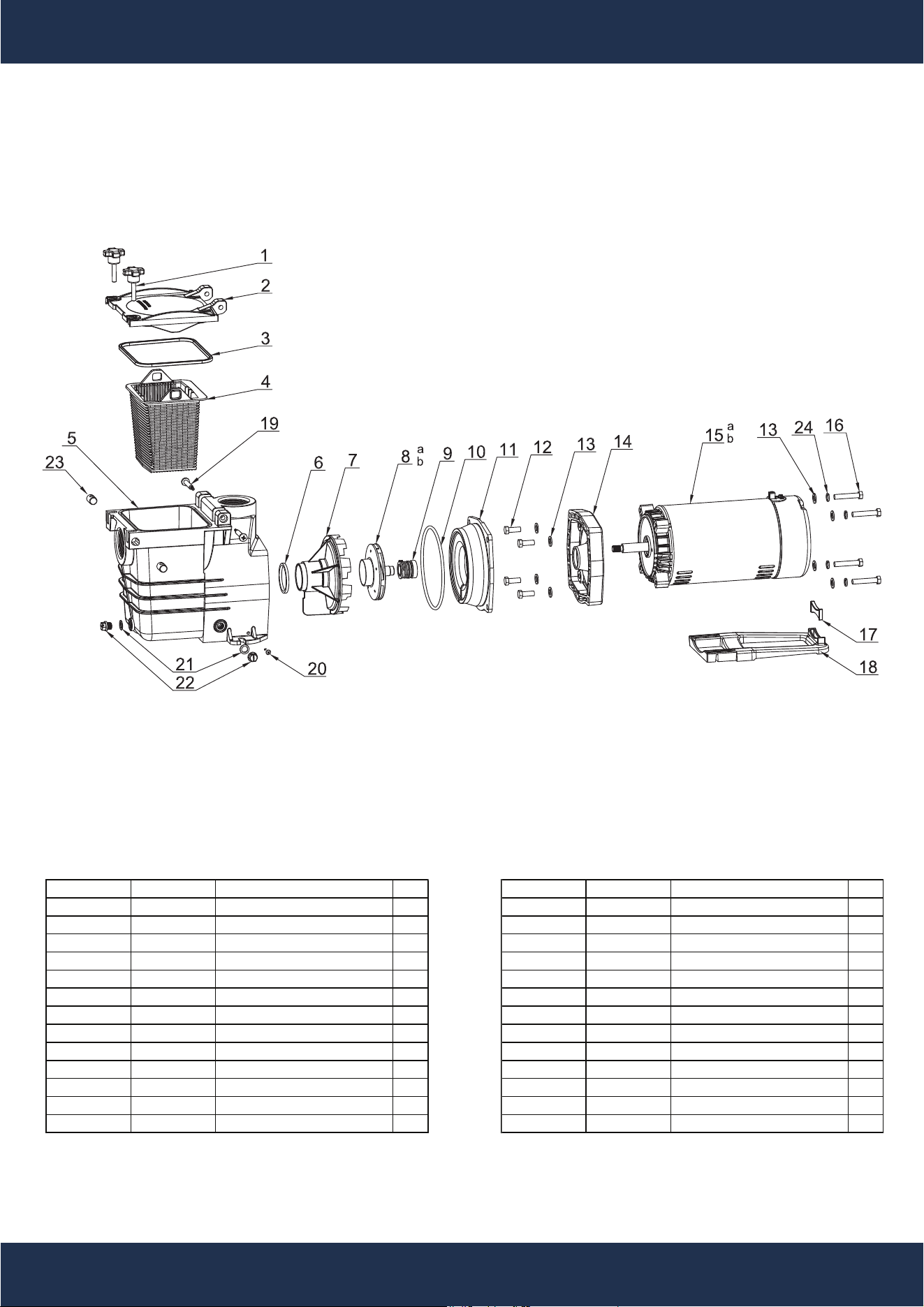
In-ground Pump Item #ʼs 75406
14
PARTS LIST
Drawing No. Part No. Description QTY Drawing No. Part No. Description QTY
1 P75406-010 Handle Screws 2 13 P75406-140 Gasket M10 8
2 P75406-020 Cover 1 14 P75406-150 Over Cover 1
3 P75406-030 Gasket 1 15a 1.0HP Motor for 90555 1
4 P75406-040 Basket 1 15b P75406-170 1.5HP Motor for 75406 1
5 P75406-050 Pump Housing 2" 1 16 P75406-180 Screw 3/8-16UNC*50.8mm 4
6 P75406-060 0-Ring 1 17 P75406-190 Foot Insert Wife Pump 1
7 P75406-070 Diffuser 1 18 P75406-200 Mounting Foot 1
8a Impeller For 90555 1 19 P75406-210 Screw ST4.8*15 2
80 P75406-090 Impeller For 75406 1 20 P75406-220 Screw ST4.8*25 2
9 P75406-100 Seal Assembly 1 21 P75406-230 Drain Plug Gasket 2
10 P75406-110 O-Ring 1 22 P75406-240 Drain Plug 2
11 P75406-120 Pump Cover 1 23 P75406-250 Reseller 2
12 P75406-130 Screw 3/8-16UNC*25.4mm 4 24 P75406-260 Spring Washer
4

15
DISCLAIMER
DISCLAIMER
PLEASE READ THE FOLLOWING CAREFULLY
The manufacturer and/or distributor have provided the parts list and assembly diagram in this manual for
reference purposes only. They do not make any representation or warranty to the buyer that they are qualified
to make repairs to the product or replace any parts of the product. In fact, the manufacturer and/or distributor
expressly state that all repairs and parts replacements should be undertaken by certified and licensed
technicians, and not by the buyer.
The buyer assumes all risk and liability arising from their repairs to the original product or replacement parts
or arising from their installation of replacement parts. It is strongly advised that qualified professionals handle
any repairs or replacements to ensure safety and proper functioning of the product. Improper installation and
operation may result in injury, property damage, or voiding of warranty. The manufacturer and/or distributor
shall not be held responsible for any accidents, damages, or malfunctions resulting from the buyer's
installation and operation of the product. It is essential to follow all safety guidelines and recommendations
provided in this manual and to seek professional assistance if unsure about the installation or operation
procedures.
