© Bosch Automotive Service Solutions Inc.
WARNING: Wear eye
protection that meets ANSI
Z87.1 and OSHA standards.
Sheet No.
Issue Date: Rev. A, April 19, 2017
Twin Cam Inner Cam Bearing Remover Kit
Form No. 579899
Parts List &
Operating Instructions for:
4847
4847A
655 Eisenhower Drive
Owatonna, MN 55060 USA
Phone: (507) 455-7000
Tech. Serv.: (800) 533-6127
Fax: (800) 955-8329
Order Entry: (800) 533-6127
Fax: (800) 283-8665
International Sales: (507) 455-7223
Fax: (507) 455-7063
1 of 2
2
3
4
5 7
8
9
1
9
6
6
11
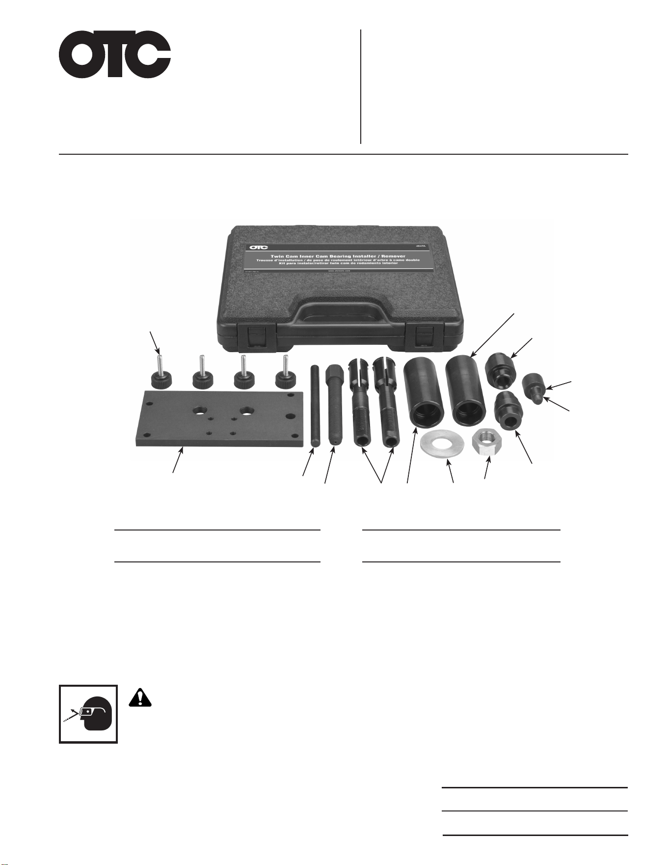
Item
No. Qty. Description
Item
No. Qty. Description
1 4 Thumb Screw
2 1 Plate Installer, Cam Bearing
3 1 Dowel Pin
4 1 Forcing Screw
5 2 Inner Cam Bearing Puller
6 2 Remover Body
7 1 Brass Washer, ¾-in.
8 1 Nut, Hex
9 2 Installer Tool, Cam Bearing
10 1 O- Ring
11 1 Driver Tool, Cam Bearing
10
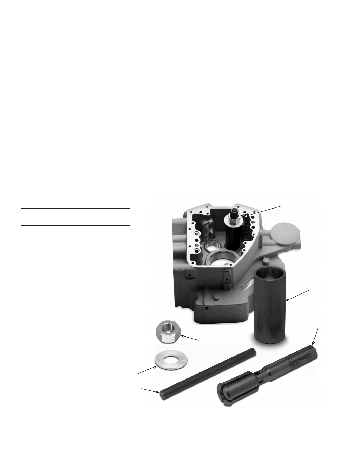
Cam Bearing Removal Instructions
CAUTION: The cam bearing remover kit includes two inner cam bearing pullers. The smaller diameter bearing
puller is used for cam bearings on early models. The larger diameter puller is used for cam bearings on late
twin cams. Select the proper size bearing puller for your particular-size bearing. There is also an associated
remover body for each bearing puller. The smaller diameter remover body is used with the smaller bearing
puller. The larger diameter remover body is used with the larger bearing puller.
1. Push the inner cam bearing puller (item 4) through the cam bearing (grooved end rst). You can tap the
end of bearing puller with a soft, dead-blow hammer until the puller is completely through the cam bearing.
See Figure 1.
2. Slide the remover body (5) over the end of the bearing puller (4). Ensure the bore of the remover body is
facing the cam bearing.
3. Apply a small amount of lubricating oil to the face of the washer and the threads on the nut. Then slide
the washer over the end of the puller and thread the nut onto the end of the puller.
4. Tighten the nut (1) until the washer (2) is snug against the remover body (5).
5. Apply a small amount of lubricating oil to the dowel pin (3) and insert the dowel pin through the center of
the bearing puller (4) until its ush with the top of the puller.
6. With a 1⅛-in. wrench, turn the nut clockwise until the bearing pulls free from the case. To prevent the
puller from turning, hold the bearing puller with a ⅝-in. wrench. CAUTION: Do not turn the bearing puller
with the ⅝-in. wrench. Damage to the tool could result.
Figure 1
Parts List and Operating Instructions Form No.
579899
, back, sheet 1 of 2
Item
No. Qty. Description
1 1 Nut, Hex
2 1 Brass Washer, ¾-in.
3 1 Dowel Pin
4 2 Inner Cam Bearing Puller
5 2 Remover Body
2
1
5
4
3
Assembled
Puller
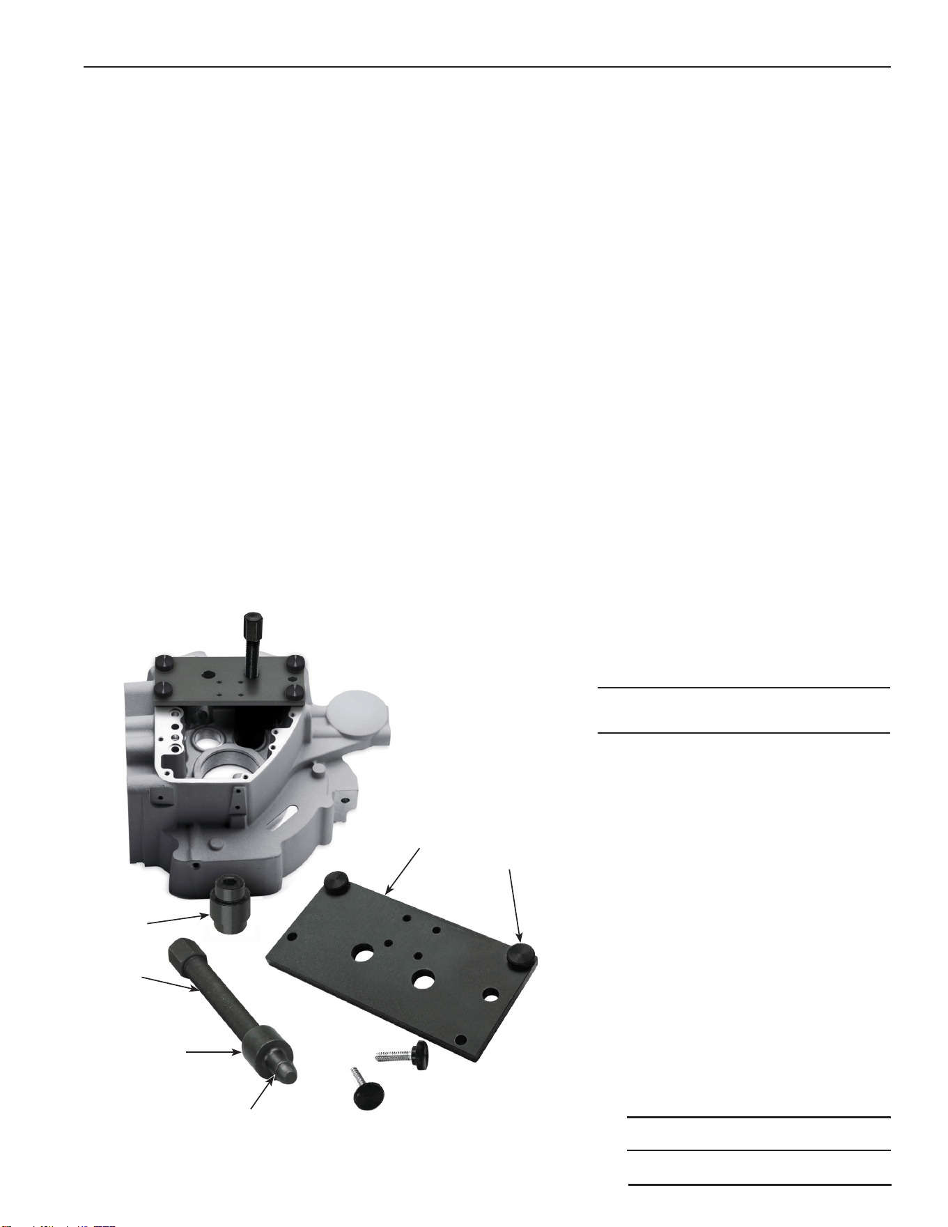
Cam Bearing Installation Instructions
1. Apply a small amount of lubricating oil to the threads of the forcing screw (item 2). Then thread the forcing
screw into the cam bearing installer plate (6). See Figure 2.
2. Thread the cam bearing driver tool (3) onto the end of the forcing screw (2).
CAUTION: On the cam bearing installer tool (1), notice that one end of the tool has a larger step than the
other end. The small step is used for cam bearings on early models. The large step is used for cam bearings
on late twin cams. Select the proper end of the installer tool for your particular-size bearing.
3. Select the proper end of the cam bearing installer tool (1) for your particular cam bearing, then push the
other end of the installer tool onto the end of the cam bearing driver tool (3). Make sure the O-ring (4) on
the end of the driver tool is in place when attaching the installer tool.
4. Before installing a new cam bearing, pay attention to the letters and numbers marked on the bearing.
The bearing must be oriented with the letters and numbers facing outward (up) against the cam bearing
installer tool (1).
5. Apply bearing assembly lubrication on the outside diameter of the cam bearing.
6. Align the two large holes in the installer plate over the bearing bores.
7. Attach the assembled tool (with bearing in position) to the cam housing case, using four lubricated thumb
screws (5). CAUTION: Lubricate the threads on each thumb screw before threading them into place.
8. Ensure the threads on the forcing screw (2) are well lubricated. Then carefully and slowly, turn the forcing
screw clockwise. Once the bearing safely clears the bore, continue to tighten the forcing screw until the
bearing is fully seated in the bore. Repeat the process for the next bearing.
9. After the new bearings are pressed in place, remove the plate from cam housing case.
Item
No. Qty. Description
1 2 Installer Tool, Cam Bearing
2 1 Forcing Screw
3 1 Driver Tool, Cam Bearing
4 1 O- Ring
5 4 Thumb Screw
6 1 Installer Plate, Cam Bearing
Figure 2
Sheet No.
Issue Date: Rev. A, April 19, 2017
Parts List & Operating Instructions Form No. 579899
2 of 2
1
6
4
3
2
5