Shenzhen Uascent Technology Co., Ltd
www.uascent-iot.com
1
Office: Zhongxing Hotel (Qianhai HOP International), No.
19, Xinghua 1st Road (Extension), Haiwang Community,
Xin'an Street, Bao'an District, Shenzhen, 2101
TEL: +86-0755-82571152
E-MAIL: marketing@uascent-iot.com
Website: www.uascent-iot.com
Customer Approval : Company
Title
Signature
Date
UAW192
Wi-Fi Single-band 1T1R 802.11b/g/n
Module Datasheet
Shenzhen Uascent Technology Co., Ltd

Shenzhen Uascent Technology Co., Ltd
www.uascent-iot.com
UAW192
3
CONTENTS
1 Overview. ..................................................................................................................................4
1.1 Introduction. ............................................................................................................................4
1.2 Features. ................................................................................................................................. 4
1.3 Recommended Operating Rating. .............................................................................................. 4
1.4 Reference power consumption for conventional continuous operation. .......................................... 4
1.5 ESD Specifications .................................................................................................................. 4
2 Module use precautions. ............................................................................................................ 5
3 WiFi Specification. .................................................................................................................... 5
4 Bluetooth Specification. ............................................................................................................. 5
5 Pin Descriptions. ....................................................................................................................... 6
5.1 Pin Outline. ............................................................................................................................. 6
5.2 Pin Definition. ......................................................................................................................... 6
6 Dimensions. ...............................................................................................................................7
6.1 Module Picture. ....................................................................................................................... 7
7 Antenna Information. ................................................................................................................7
7.1 Antenna type. .......................................................................................................................... 7
8 Environmental Requirements. ................................................................................................... 8
8.1 Recommended Reflow Profile. .................................................................................................. 8
8.2 Note. .......................................................................................................................................8
9 Package. ..................................................................................................................................10
9.1 Packaging Detail. ................................................................................................................... 10
10 Transport regulations. ...........................................................................................................10
11 Disclaimer and copyright notice. ............................................................................................10
12 Attention. .............................................................................................................................. 11
13 FCC statements: ................................................................................................................... 11
14 ANATEL statements: ............................................................................................................ 13
15 IC statements: ....................................................................................................................... 13
UAW192
Shenzhen Uascent Technology Co., Ltd
4
www.uascent-iot.com
1 Overview.
1.1 Introduction.
UAW192 is a cost-effective WIFI+BLE low-power module developed by Uascent Technology,
supporting IEEE 802.11 b/g/n and BLE 4.2 protocol standards, as well as STA, AP, and Direct
modes. Users can use this module to add networking functions to existing devices or build
independent network controllers.
1.2 Features.
Support 20 MHz channel.
Standard IEEE 802.11b/g/n.
Support BLE 1 Mbps
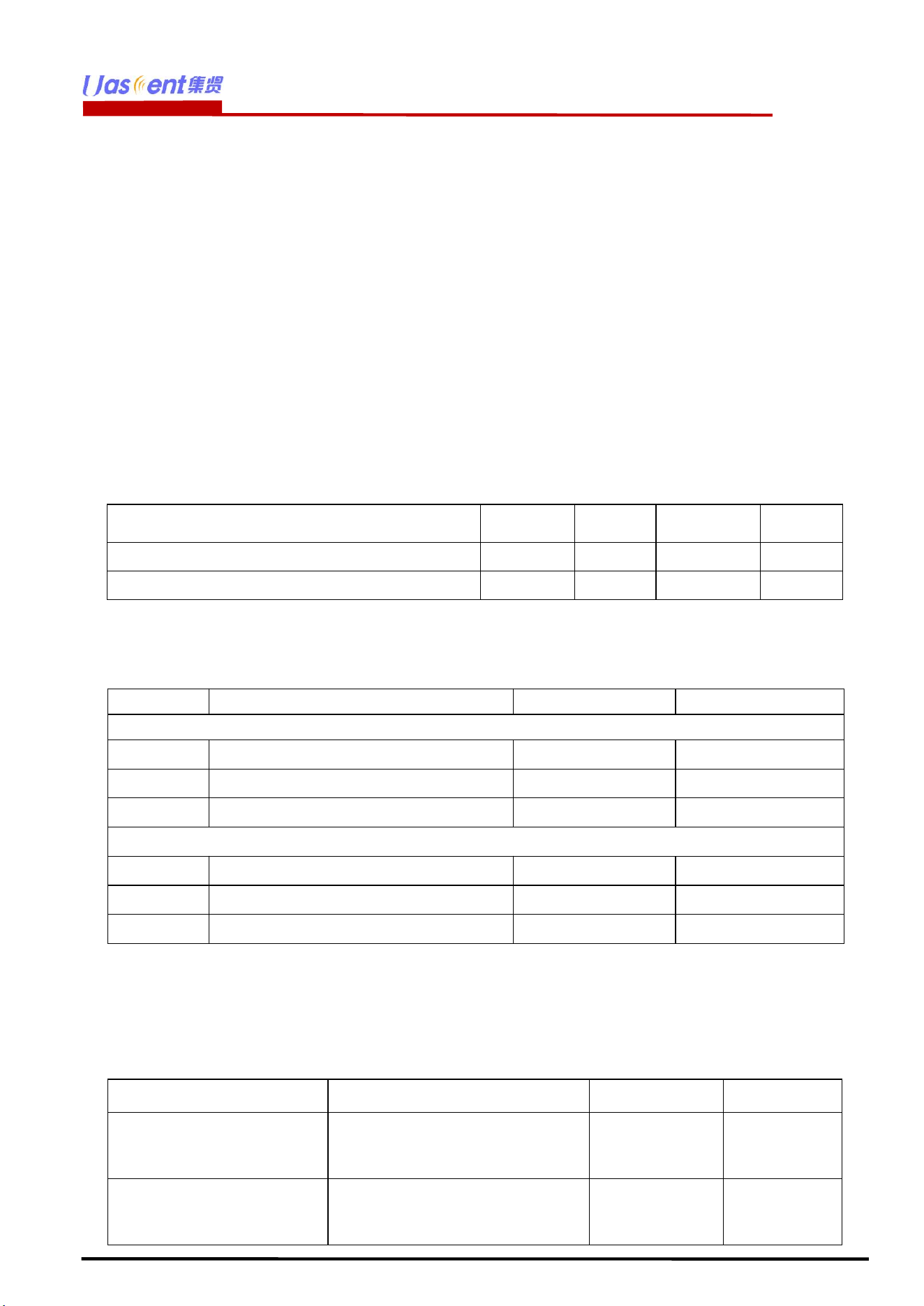
1.3 Recommended Operating Rating.
Description
Min
Typ
Max
Unit
Ambient Temperature (TA)
-10
25
85
deg.C
Vcc
5
12
12
V
1.4 Reference power consumption for conventional continuous operation.
Parameter
Condition / Notes
Typ.
Unit
TX Mode
I
RF
11b 11M
225
mA
I
RF
11g 54M
166
mA
I
RF
11n HT20 MCS7
160
mA
RX Mode
I
RF
11b 11M
46
mA
I
RF
11g 54M
46
mA
I
RF
11n HT20 MCS7
46
mA
1.5 ESD Specifications
Item
Description
Value
Unit
Human Body Mode (HBM)
Electrostatic Discharge Tolerance
under Human
Body Model
±2
KV
CDM
Electrostatic Discharge Tolerance
under Charged
Device Model
±0.5
KV
UAW192
Shenzhen Uascent Technology Co., Ltd
5
www.uascent-iot.com
2 Module use precautions.
When using the WIFI module of Uascent Technology, a certain tolerance should be reserved for the output
current of the power supply. It is recommended that the output current of the power supply be ≥ 500mA, and a
suitable power supply IC packaging should be selected. When using LDO power, attention should be paid to the
issue of thermal, and when using DC-DC power, attention should be paid to the issue of overshoot at the
moment of power on.
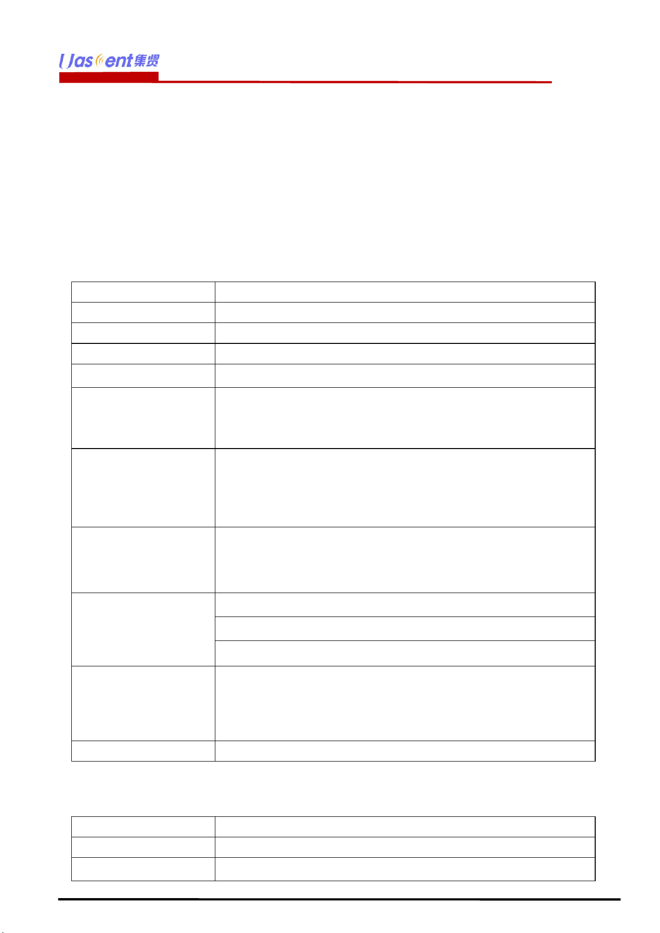
3 WiFi Specification.
Features
Descriptions
Main Chipset
REALTEK
:
RTL8720CF
Operating Frequency
2400~2483.5MHz
Operating Voltage
5~12V
WIFI Standard
IEE 802.11b/g/n
PHY Data rates
Wi-Fi: 802.11b: 11, 5.5, 2, 1 Mbps
802.11g: 54, 48, 36, 24, 18, 12, 9, 6 Mbps
HT20 MCS0-MCS7
Transmit Output
Power
Wi-Fi: 802.11b@11Mbps 16±2dBm
802.11g@54Mbps 15±2dBm
802.11n@HT20 MCS7 14±2dBm
EVM
802.11b /11Mbps: EVM≦-10dB
802.11g /54Mbps: EVM≦-25dB
802.11n /HT20 MCS7: EVM≦-27dB
Receiver Sensitivity
(HT20)
802.11b@8% PER11Mbps≤ -89dBm
802.11g@10% PER 54Mbps≤-76dBm
802.11n@10% PER MCS 7 ≤-73dBm
Operating Channel
Wi-Fi 2.4GHz:
11: (Ch. 1-11) – United States(North America)
13: (Ch. 1-13) – Europe
14: (Ch. 1-14) – Japan
Antenna
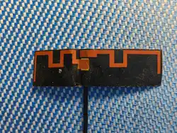
PCB onboard antenna
4 Bluetooth Specification.
Features
Descriptions
Operating Frequency
2.402
~
2.480GHz
BLE version
4.2
UAW192
Shenzhen Uascent Technology Co., Ltd
6
www.uascent-iot.com
Data rate
Typical : 1Mbps
Tx output power
6.5dBm(Max)
Rx sensitivity (PER 1500
packet data ≤ 30.8%)
-96dBm
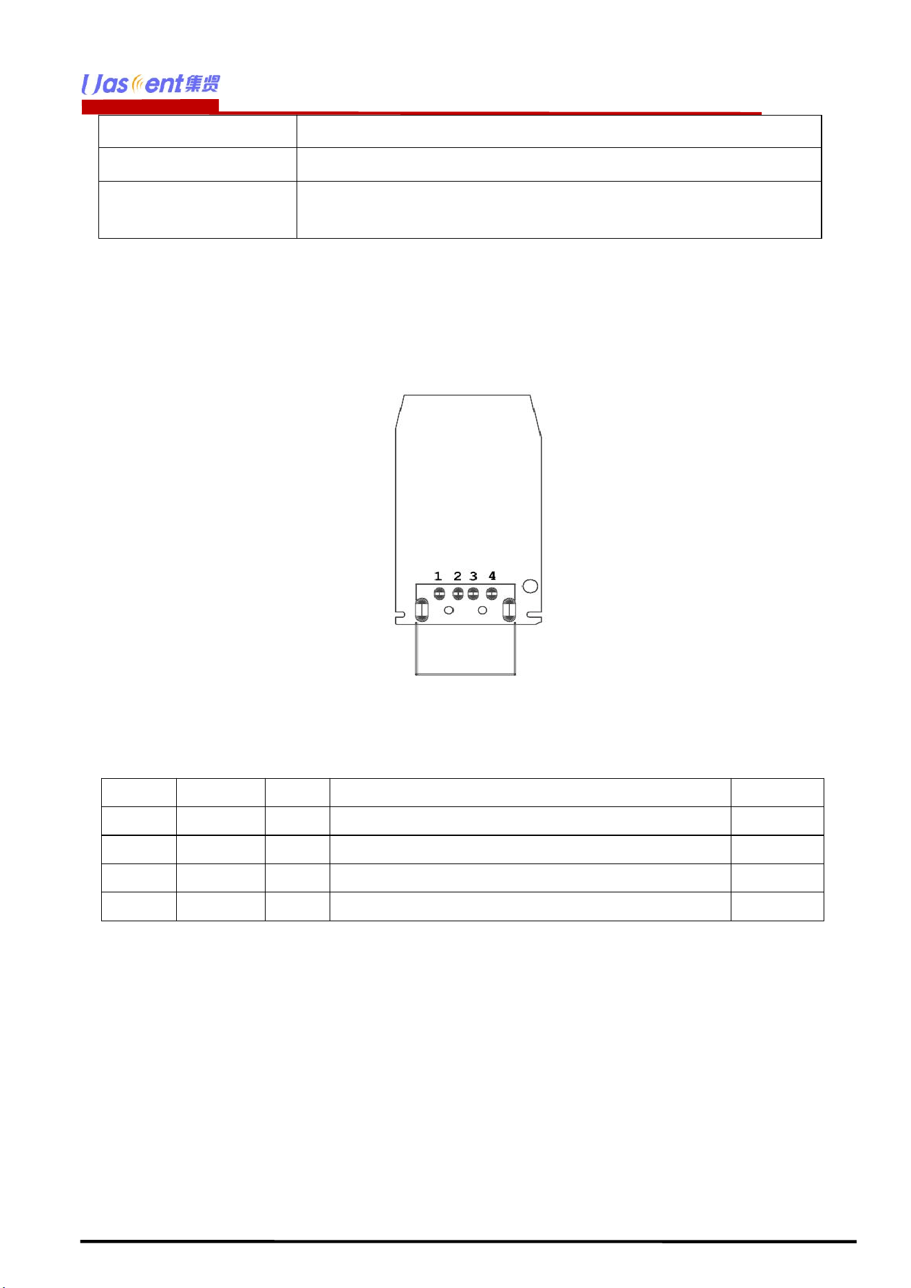
5 Pin Descriptions.
5.1 Pin Outline.
<TOP>
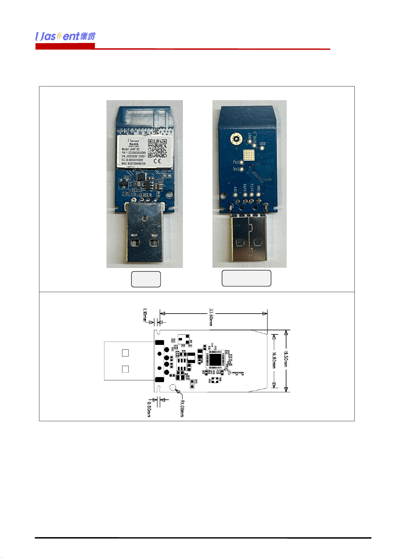
5.2 Pin Definition.
Pin No.
Name
Type
Description
Voltage
1
GND
P
Ground
3.3V
2
TX
O
WiFi UART TX
3
RX
I
WiFi UART RX
4
VDD
I/O
Supply 12V
※ P:POWER I:INPUT O:OUTPUT
UAW192
Shenzhen Uascent Technology Co., Ltd
8
www.uascent-iot.com
8 Environmental Requirements.
8.1 Recommended Reflow Profile.
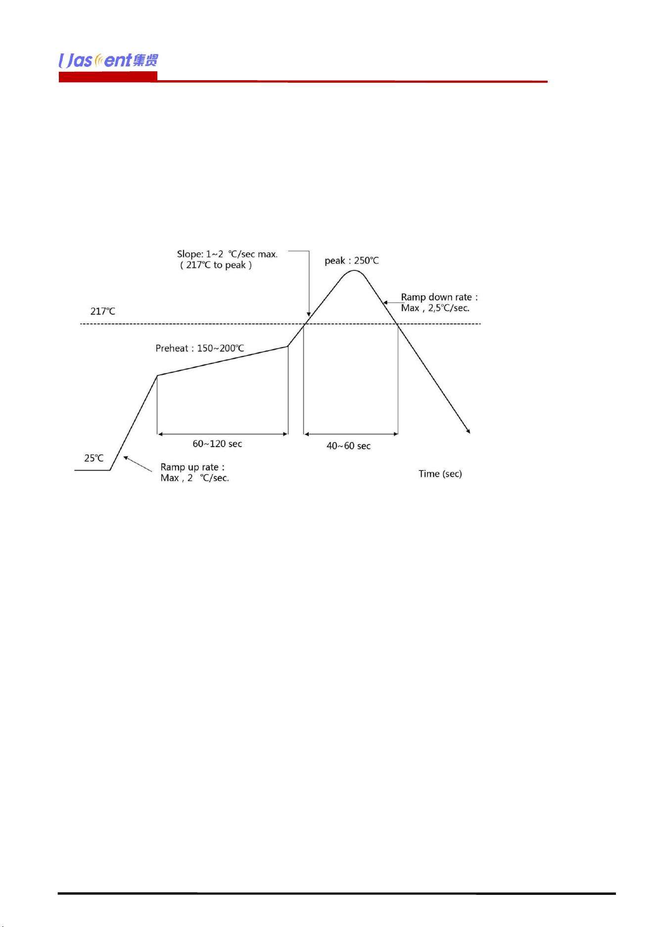
Referred to IPC/JEDEC standard.
Peak Temperature : <250°C Number
of Times : ≤2 times
8.2 Note.
Note:Take and use the module, please insure the electrostatic protective measures.
1. Reflow soldering temperature should be according to the customer the main size of the
products, such as the temperature set at 250 + 5 ℃ for the MID motherboard. About the module
packaging, storage and use of matters needing attention are as follows:
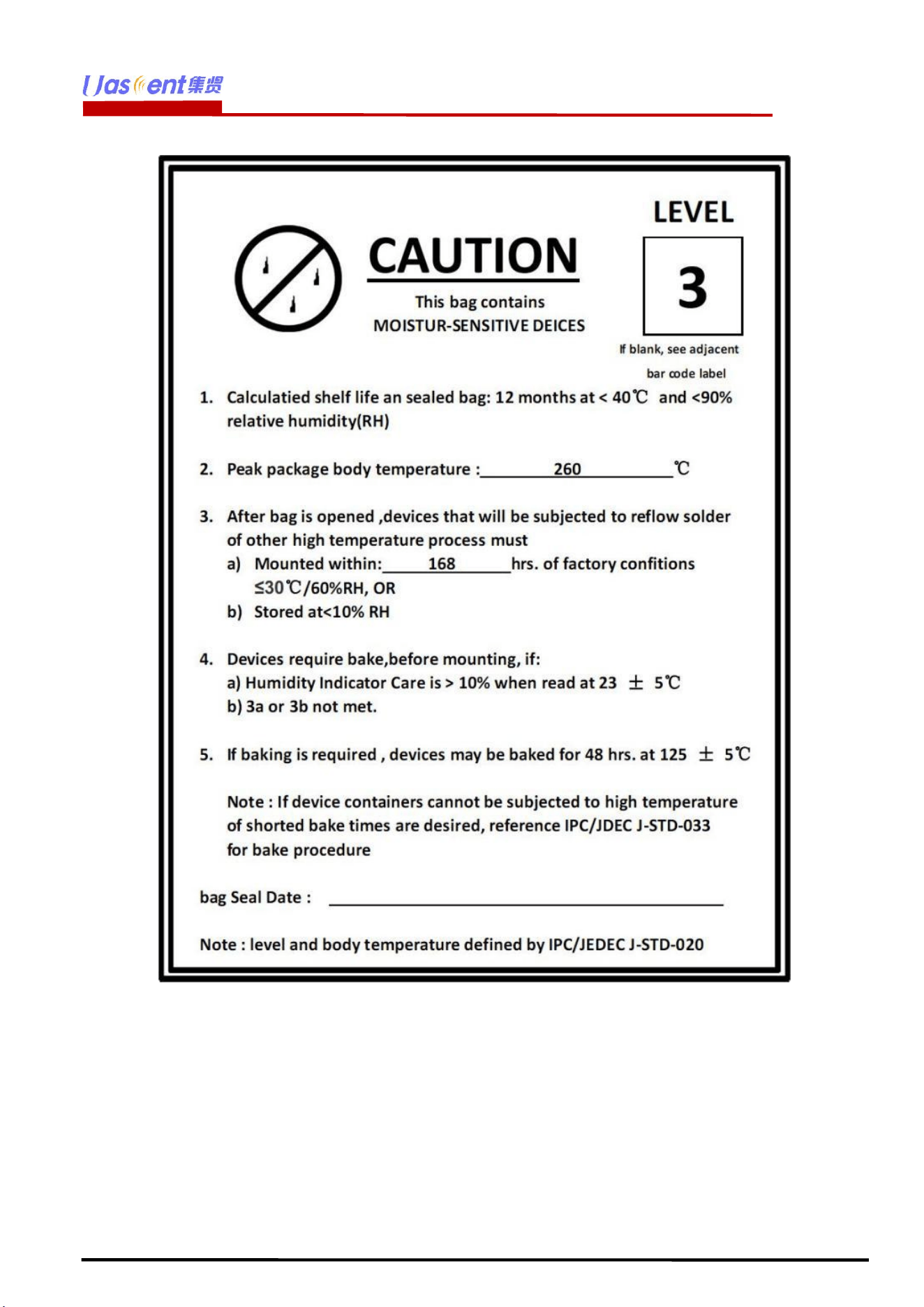
2. The module of the reel and storage life of vacuum packing: 1). Shelf life: 8 months, storage
environment conditions: temperature in: < 40 ℃, relative humidity: < 90% r.h.
3. The module vacuum packing once opened, time limit of the assembly:
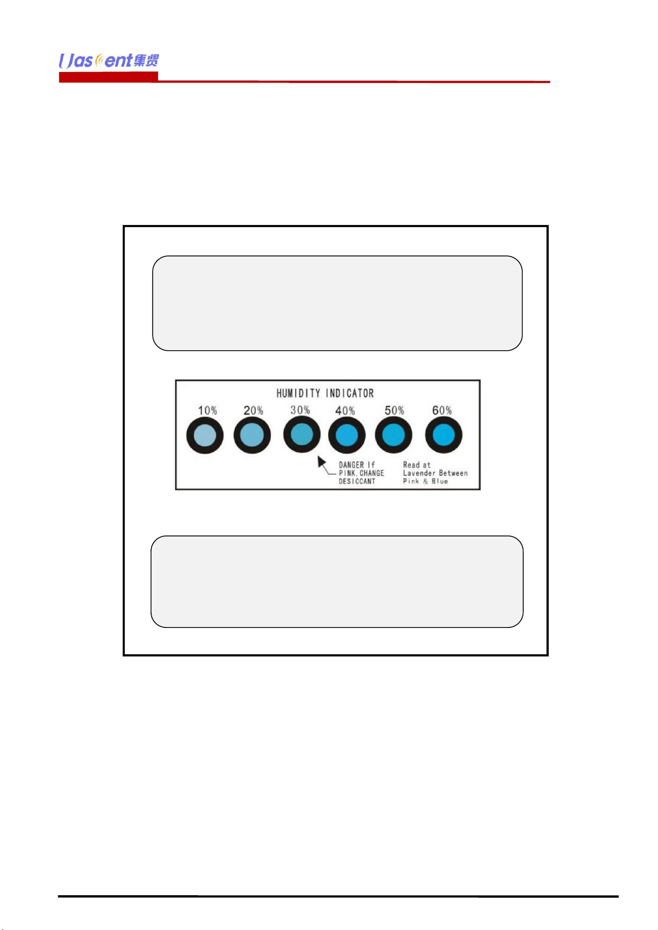
Card:1) check the humidity display value should be less than 30% (in blue), such as: 30% ~ 40%
(pink), or greater than 40% (red) the module have been moisture absorption. 2.) factory
environmental temperature humidity control: ≦ -30 ℃, ≦ 60% r.h..
3). Once opened, the workshop the preservation of life for 168 hours.
4. Once opened, such as when not used up within 168 hours:
1). The module must be again to remove the module moisture absorption. 2). The
baking temperature: 125 ℃, 8 hours.
3). After baking, put the right amount of desiccant to seal packages.
UAW192
Shenzhen Uascent Technology Co., Ltd
10
www.uascent-iot.com
9
Package.
9.1 Packaging Detail.
The module and the humidity indicator card are placed together in vacuum anti-static packaging,
separated by a certain amount of paper, and neatly placed in the packaging box.The packaging must
have reliable moisture-proof and anti-collision measures.
10
Transport regulations.
In the process of logistics or express transportation, attention should be paid to handling with care to
avoid direct rain and snow.
11
Disclaimer and copyright notice.
All information in this document is provided according to the product status quo and subject to change
without notice.
The contents of this document disclaim any warranties, including any warranties of fitness for sale,
fitness for a particular purpose or non-infringement, and any warranties mentioned elsewhere in any
proposal, specification or sample.
Note1:
There is a "triangular arrow" on the humidity indicator card
indicating at 30%RH (as shown in the picture below). If the
chemical changes to pink in the circle it points to, the
element is damp and needs baking.
Note2:
Please confirm the packaging style with our sales staff
before purchasing this product. If no packing style is
specified before purchase, we will ship the goods by our
own choice of packing method.

UAW192
Shenzhen Uascent Technology Co., Ltd
11
www.uascent-iot.com
This document is not liable for any infringement of patent rights arising from the use of the information
contained in this document.
This document does not grant any license, express or implied, to use any intellectual property rights,
estoppel or otherwise.
All trademarks mentioned herein are the property of their respective owners.
12 Attention.
Due to product version upgrade or other reasons, the content of this manual may be changed. Shenzhen
Uascent Technology Co., Ltd. reserves the right to modify the content of this manual without any notice
or prompt. If users need to obtain the latest product information, please apply for the final document with
our company.This manual is only used as a guide. Shenzhen Uascent Technology Co., Ltd. tries its best
to provide the latest information in this manual, but does not guarantee that the content of the manual is
completely accurate.
None of the statements, information and recommendations contained in this manual constitute any
warranty, express or implied.
13 FCC regulatory compliance statement:
§15.19 Statement
This device complies with Part 15 of the FCC Rules. Operation is subject to the following two conditions:
(1) this device may not cause harmful interference, and (2) this device must accept any interference
received, including interference that may cause undesired operation.
§15.21 Information to user
Warning: changes or modifications not expressly approved by the party responsible for compliance could
void the user’s authority to operate the equipment.
RF Exposure Compliance
This equipment complies with FCC radiation exposure limits set forth for an uncontrolled environment.
This transmitter must not be co-located or operating in conjunction with any other antenna or transmitter.
This equipment should be installed and operated with minimum distance 20cm between the radiator and
your body.
List of applicable FCC rules:
47 CFR Part 15.247
Summarize the specific operational use conditions
This module can be used in IOT devices, the input voltage to the module is nominally 12V.
Limited module procedures
This module is a Single Modular.
Trace antenna designs
The antenna is not a trace antenna.
RF exposure considerations
This Module complies with FCC radiation exposure limits set forth for an uncontrolled environment.
This equipment should be installed and operated with a minimum distance of 20cm between the radiator
and your body. This transmitter must not be co-located or operating in conjunction with any other
antenna or transmitter.
Antennas
If you desire to increase antenna gain and either change antenna type or use same antenna type certified,
a Class II permissive change application is required to be filed by us, or you (host manufacturer) can take
responsibility through the change in FCC ID (new application) procedure followed by a Class II
UAW192
Shenzhen Uascent Technology Co., Ltd
12
www.uascent-iot.com
permissive change application.
Label and compliance information
Please notice that if the FCC identification number is not visible when the module is installed inside
another device, then the outside of the device into which the module is installed must also display a label
referring to the enclosed module. This exterior label can use wording such as the following: “Contains
FCC ID: 2A68E-UAW192” any similar wording that expresses the same meaning may be used.
§ 15.19 Labelling requirements shall be complied on end user device.
Labelling rules for special device, please refer to §2.925, § 15.19 (a)(5) and relevant KDB publications.
For E-label, please refer to §2.935.
Information on test modes and additional testing requirements
The OEM integrator is responsible for ensuring that the end-user has no manual instruction to remove or
install module. The module is limited to installation in mobile application, a separate approval is required
for all other operating configurations, including portable configurations with respect to §2.1093 and
difference antenna configurations.
FCC other Parts, Part 15B Compliance Requirements for Host product manufacturer
This modular transmitter is only FCC authorized for the specific rule parts listed on our grant, host
product manufacturer is responsible for compliance to any other FCC rules that apply to the host not
covered by the modular transmitter grant of certification. Host manufacturer in any case shall ensure host
product which is installed and operating with the module is in compliant with Part 15B
requirements.Please note that For a Class B or Class A digital device or peripheral, the instructions
furnished the user manual of the end-user product shall include statement set out in §15.105 Information
to the user or such similar statement and place it in a prominent location in the text of host product
manual. Original texts as following:
For Class B
Note: This equipment has been tested and found to comply with the limits for a Class B digital device,
pursuant to part 15 of the FCC Rules. These limits are designed to provide reasonable protection against
harmful interference in a residential installation. This equipment generates, uses and can radiate radio
frequency energy and, if not installed and used in accordance with the instructions, may cause harmful
interference to radio communications. However, there is no guarantee that interference will not occur in
a particular installation. If this equipment does cause harmful interference to radio or television
reception, which can be determined by turning the equipment off and on, the user is encouraged to try to
correct the interference by one or more of the following measures:
—Reorient or relocate the receiving antenna.
—Increase the separation between the equipment and receiver.
—Connect the equipment into an outlet on a circuit different from that to which the receiver is
connected.
—Consult the dealer or an experienced radio/TV technician for help.
For Class A
Note: This equipment has been tested and found to comply with the limits for a Class A digital device,
pursuant to part 15 of the FCC Rules. These limits are designed to provide reasonable protection against
harmful interference when the equipment is operated in a commercial environment. This equipment
generates, uses, and can radiate radio frequency
energy and, if not installed and used in accordance with the instruction manual, may cause harmful
interference to radio communications. Operation of this equipment in a residential area is likely to cause
harmful interference in which case the user will be required to correct the interference at his own
expense.
EMI Considerations
As best practice per FCC D04 Module Integration Guide, host manufacturer shall perform RF design test
& evaluation. Non linear coupling between module and host components may cause EMI non
compliance. Stand alone operation follows D04 guidance; for simultaneous multi transmitter operation,

UAW192
Shenzhen Uascent Technology Co., Ltd
13
www.uascent-iot.com
refer to FCC D02 Q&A Question12 for host compliance confirmation.
How to make changes
Only the FCC grant holder is authorized to perform permissive changes to this module. If host intends to
use the module under conditions different from original grant approval, host shall contact module grant
holder for guidance.
14 ANATEL statements:
Este equipamento não tem direito à proteção contra interferência prejudicial e não pode causar
interferência em sistemas devidamente autorizados. Para mais informações, consulte o site da ANATEL
– https://www.gov.br/anatel/pt-br
15 IC statements:
ISED compliance statement
This device contains licence-exempt transmitter(s)/receiver(s) that comply with Innovation, Science and
Economic Development Canada’s licence-exempt RSS(s). Operation is subject to the following two
conditions:
(1) This device may not cause interference.
(2) This device must accept any interference, including interference that may cause undesired operation
of the device.
L’émetteur/récepteur exempt de licence contenu dans le présent appareil est conforme aux CNR
d’Innovation, Sciences et Développement économique Canada applicables aux appareils radio exempts
de licence. L’exploitation est autorisée aux deux conditions suivantes :
(1) L’appareil ne doit pas produire de brouillage;
(2) L’appareil doit accepter tout brouillage radioélectrique subi, même si le brouillage est susceptible
d’en compromettre le fonctionnement.
ISED Radiation Exposure statement
This equipment complies with IC RSS-102 radiation exposure limits set forth for an uncontrolled
environment. This equipment should be installed and operated with minimum distance 20 cm between
the radiator and your body.
Cet équipement est conforme aux limites d'exposition aux radiations IC CNR-102 établies pour un
environnement non contrôlé. Cet équipement doit être installé et utilisé avec une distance minimale de
20 cm entre le radiateur et votre corps. Cet émetteur ne doit pas être colocalisé ou fonctionner en
conjonction avec une autre antenne ou un autre émetteur.
Please notice that if the IC identification number is not visible when the module is installed inside
another device, then the outside of the device into which the module is installed must also display a label
referring to the enclosed module. This exterior label can use wording such as the following: “Contains
IC:31130-UAW192” any similar wording that expresses the same meaning may be used.
L’étiquette d’homologation d’un module d’Innovation, Sciences et Développement économique Canada
devra être posée sur le produit hôte à un endroit bien en vue, en tout temps. En l’absence d’étiquette, le
produit hôte doit porter une étiquette sur laquelle figure le numéro d’homologation du module
d’Innovation, Sciences et Développement économique Canada, précédé du mot « contient », ou d’une
formulation similaire allant dans le même sens et qui va comme suit :
Contient IC:31130-UAW192 est le numéro d’homologation du module
This radio transmitter [IC:31130-UAW192] has been approved by Innovation, Science and Economic
Development Canada to operate with the antenna types listed below, with the maximum permissible gain
indicated. Antenna types not included in this list that have a gain greater than the maximum gain
indicated for any type listed are strictly prohibited for use with this device.
a list of all antenna types