
www.silicontra.com CC2500MPATR2.4-V
Tel
:+86-0755-33592127
The copyrights belongs to the company
1 / 11
SHENZHEN SILICONTRA TECHNOLOGY CO.,LTD.
CC2500MPATR2.4-V
2.4GHz RF modules
(V2.0)
Catalogue
1. Modules introduction ................................................................................................................................................ 2
2. Parameters .................................................................................................................................................................. 4
2.1 Essential parameter ................................................................................................................................................. 4
3. Modules description ..................................................................................................................................................5
4. Hardware design
........................................................................................................................................................ 7
5. Transmission issue
.....................................................................................................................................................8
6. Modules damage inspection
................................................................................................................................... 8
7. High bit error rate issue
............................................................................................................................................8
Revision record
Versions
Change date
Change content
V1.0
2019-4-16
Original version
V2.0
2022-8-17
1. Format optimization
2. Add antenna selection
www.silicontra.com CC2500MPATR2.4-V
Tel
:+86-0755-33592127
The copyrights belongs to the company
2 / 11
1. Modules introduction
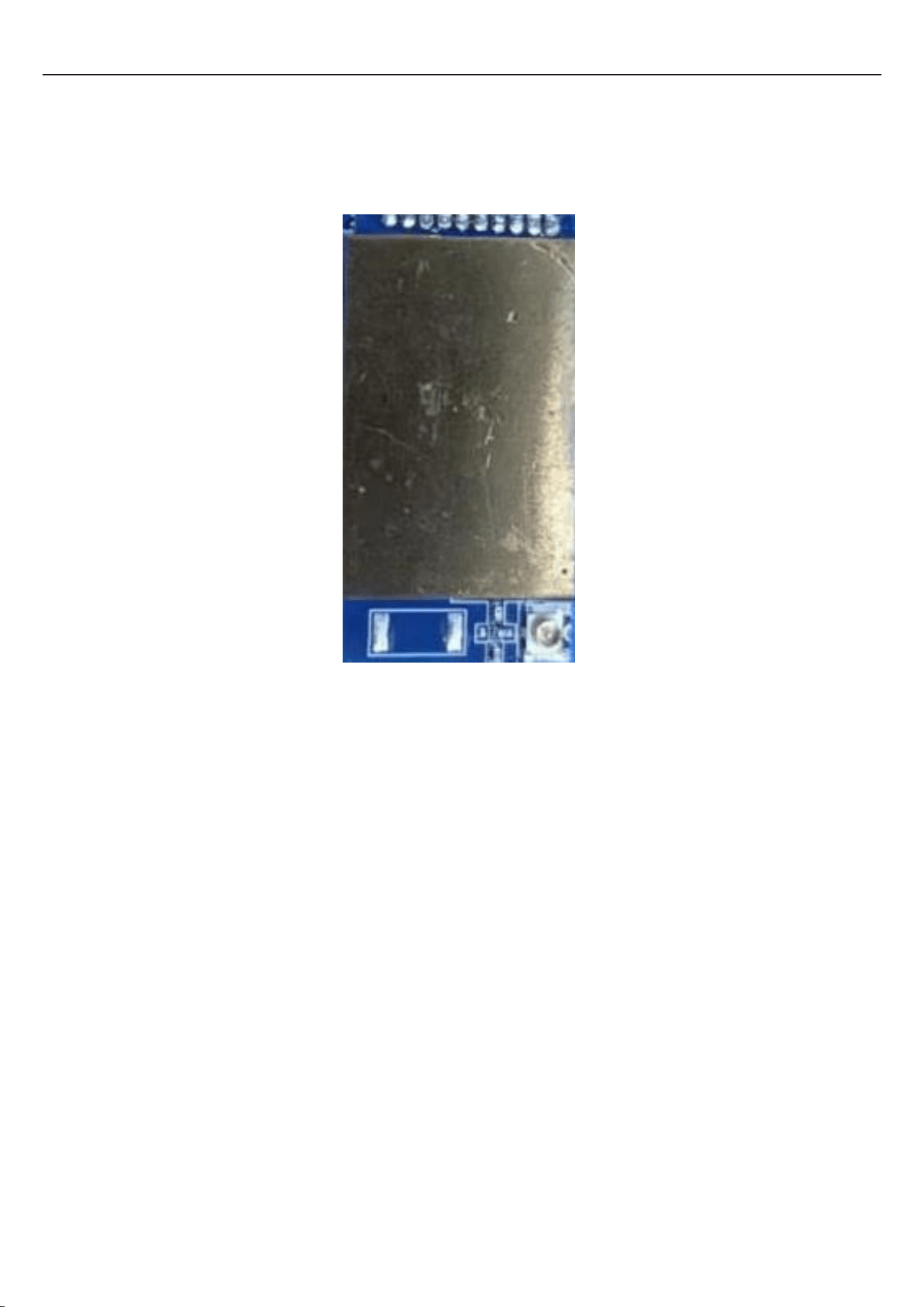
(Subject to physical goods)
1.1 Brief introduction
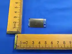
CC2500MPATR2.4-V is developed by the RF-chip CC2500. It is a truly low-cast, highly
integrated 2.4GHz module designed for remote wireless applications.
We will provide complete hardware and software solutions for you to shorten the R&D
cycle and save costs.

www.silicontra.com CC2500MPATR2.4-V
Tel
:+86-0755-33592127
The copyrights belongs to the company
3 / 11
1.2 The characteristics of modules
● Frequency 2.4GHz, can be programmed 2.4-2.483GHz.
● SMD element, 31.6*16.5mm, PCB antenna/ IPEX antenna interface optional.
● Support GFSK modulation mode.
● Set power by software
● Flexible RF channel configuration, fast switching frequency point.
● Set RF baud rate by software, 1.2k~500kbps.
● 3.3V power supply.
● SPI interface, RSSI output, carrier sense indication.
1.3 Application scenario
● Wireless sensor.
● Low power telemetry.
● AMR - automatic transcription.
● RKE - two way remote keyless login .
● Remote controlled toy.
● Wireless light control.
● Wireless alarm and security system.

www.silicontra.com CC2500MPATR2.4-V
Tel
:+86-0755-33592127
The copyrights belongs to the company
4 / 11
2. Parameters
2.1 Essential parameter
The technical parameters of CC2500MPATR
Item
Parameters
Remark
VCC
2.4 ~ 3.6V,Rated voltage: 3.3V
Frequency
2.400-2483.5MHz
Modulation
GFSK
Rx sensitivity
-122dBm
2.4kbps
TX current
<300mA
Rx current
<20mA
Sleep current
5uA
RF baud rate
1.2~500kbps
Data interface
SPI
Antenna impedance
50Ω
Storage temperature range
-50 ~ 150℃
Work Temperature range
-20 ~ 70℃
Size
31.6mm × 16.5mm
www.silicontra.com CC2500MPATR2.4-V
Tel
:+86-0755-33592127
The copyrights belongs to the company
5 / 11
3. Modules description
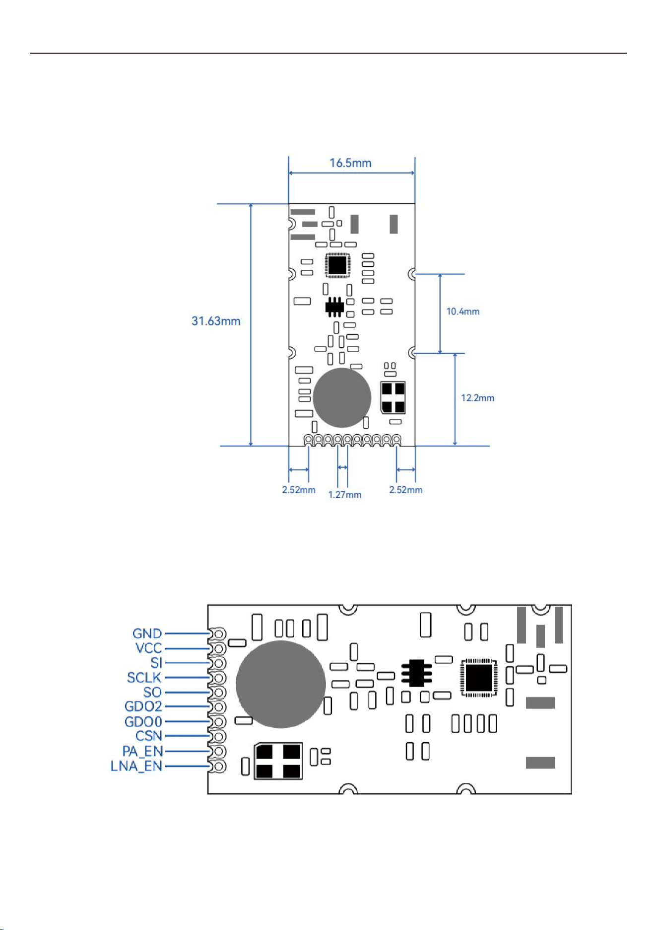
3.1 Size diagram
3.2 Pin diagram

www.silicontra.com CC2500MPATR2.4-V
Tel
:+86-0755-33592127
The copyrights belongs to the company
6 / 11
3.3 Pin function description
Num.
Name
Description
1
GND
Ground
2
VCC
DC: 1.8-3.6V, Rated voltage: +3.3V
3
SI
Data input
4
SCLK
Clock input
5
SO
Data output
6
GDO2
Data output, configured by a register
7
GDO0
Data output, configured by a register
8
CSN
Chip selection
9
PA_EN
TX: PA_EN=1 & LNA_EN=0
10
LNA_EN
RX: PA_EN=0 & LNA_EN=1
Remark: 1, MCU can use general I/O port to implement SPI interface, If SPI is 5 V level, refer to TI AN021
file for processing. GDO0, GDO2 according to the application connection, you can select one of
them as the send/receive interrupt request signal to control the MCU receive/send, or not
linking-up, and through the SPI port to read the module status to receive/send.
2, If an external antenna is selected, it can be connected to the product housing with an
extended cable. If the PCB antenna is selected, the part of PCB antenna should be floating as far
as possible, or at least the part is not grounded. PCB antenna surrounding can not have
transformers, crystals and other large metal parts to avoid affecting the distance.
3, Production can not be reflow welding, only manual welding.

www.silicontra.com CC2500MPATR2.4-V
Tel
:+86-0755-33592127
The copyrights belongs to the company
7 / 11
4. Hardware design
Recommend to use the DCDC that the power ripple coefficient is smaller to supply the power if you can,
ensure proper grounding.
Verify the power source voltage falls within the specified range and confirm correct connection of
positive and negative terminal, failure to do so may result in modules breakdown due to overvoltage or
incorrect connections.
The power supply stability should be checked and maintained consistently.
Avoid proximity to components with significant electromagnetic interface, such as the power supply,
transformer and high-frequency cable.
The cable carrying power supply or high-frequency signals should not be routed through the bottom
of the module. If there is no alternative, ensure that the module is soldered on the layer
named‘Toplayer’, with grounding perimeter areas and copper, before laying the cable on the other
layer named ‘Bottomlayer’. The cable going through below the module, even on a different layer, may
result in signal scatting and desensitization.
In case of unavoidable electromagnetic interface, ensure proper isolation and shielding by adding a
shielding case.

www.silicontra.com CC2500MPATR2.4-V
Tel
:+86-0755-33592127
The copyrights belongs to the company
8 / 11
5. Transmission issue
The transmission distance will decrease in presence of obstacles or shelter.
Changes in temperature, humidity, or frequency interface can increase packet loss rate.
Radio waves are absorbed and reflected by the ground, therefore, module performance worsens
as proximity to the ground. Recommend to keep a minimum distance of 1.5m from the ground if
possible.
Metal absorb radio waves, so it is important to keep antennas away from metal objects and avoid
placing them inside metal boxes.
The higher RF baud rate, The closer the transmission distance.
The TX power decreases as the voltage drops below the rated level.
Ensure the antenna and modules match.
6. Modules damage inspection
Check the power supply, ensure the voltage remains within the recommended range with
minimum fluctuation. Modules may become damaged if the voltage exceeds its maximum limit.
Maintain ESD protection for RF components which are electrostatic sensitive. Additionally, ensure
the humidity levels remain at an appropriate level as some components are sensitive to high
humidity levels.
Unless otherwise specified, it is not advisable to use this product in excessively high or low
temperatures.
7. High bit error rate issue
Same frequency signal interface, remove interface or modifying the frequency (interval 500MHz at
least) /RF channels.
Power supply instability, check and replace a stable one.

CC2500MPATR2.4-V
Tel
:+86-0755-33592127
The copyrights belongs to the company
9 / 11
www.silicontra.com
FCC Warning
This device complies with part 15 of the FCC rules. Operation is subject to the following two
conditions: (1) this device may not cause harmful interference, and (2) this device must accept any
inte rference received, including interference that may cause undesired operation.
Changes or modifications not expressly approved by the party responsible for compliance could
void the user's authority to operate the equipment.
NOTE: This equipment has been tested and found to comply with the limits for a Class B digital
device, pursuant to part 15 of the FCC Rules. These limits are designed to provide reasonable
protection against harmful interference in a residential installation. This equipment generates uses
and can radiate radio frequency energy and, if not installed and used in accordance with the
instructions, may cause harmful interference to radio communications. However, there is no
guarantee that interference will not occur in a particular installation. If this equipment does cause
harmful interferenceto radio or television reception, which can be determined by turning the
equipment off and on, the user is encouraged to try to correct the interference by one or more of
the following measures:
• Reorient or relocate the receiving antenna.
• Increase the separation between the equipment and receiver.
• Connect the equipment into an outlet on a circuit different from that to which the receiver
is connected.
• Consult the dealer or an experienced radio/TV technician for help.
Radiation Exposure Statement
This equipment complies with FCC radiation exposure limits set forth for an uncontrolled
environment. This equipment should be installed and operated with minimum distance 20cm
between the radiator and your body.

CC2500MPATR2.4-V
Tel
:+86-0755-33592127
The copyrights belongs to the company
10 / 11
www.silicontra.com
Integration instructions for host product manufacturers according to KDB 996369 D03 OEM Manual
v01r01
2.2 List of applicable FCC rules
CFR 47 FCC Part 15 Subpart C has been investigated. It is applicable to the modular transmitter
2.3 Specific Operational Use Conditions
This module is stand-alone modular. If the end product will involve the multiple simultaneously
transmitting condition or different operational conditions for a stand-alone modular transmitter in
a host, host manufacturer have to consult with module manufacturer for the installation method in
end system.
2.4 Limited Module Procedures
Not applicable
2.5 Trace Antenna Designs
Not applicable
2.6 RF Exposure Considerations
This equipment complies with FCC radiation exposure limits set forth for an uncontrolled
environment. This equipment should be installed and operated with minimum distance 20cm
between the radiator and your body.
2.7 Antenna Type and Gain
The module only used dipole antenna and maximum antenna gain is 2.0dBi for 2.4G.
The following antennas have been certified for use with this module.
Only antennas of the same type with equal or lower gain may also be used with this module. Other
types of antennas and/or higher gain antennas may require the additional authorization for
operation.
2.8 End Product Labelling Compliance Information
When the module is installed in the host device, the FCC ID label must be visible through a window
on the final device or it must be visible when an access panel, door or cover is easily removed. If
not, a second label must be placed on the outside of the final device that contains the following
text: “Contains FCC ID: XAO-MPATR24C”. The FCC ID can be used only
when all FCC compliance requirements are met.
2.9 Information on Test Modes and Additional Testing Requirements
This transmitter is tested in a standalone mobile RF exposure condition and any co-located
or simultaneous transmission with other transmitter(s) class II permissive change reevaluation or
new FCC authorization.
Host manufacturer installed this modular with single modular approval should perform the
test of radiated emission and spurious emission according to FCC part 15C, 15.209, 15.207
requirement, only if the test result comply with FCC part 15C, 15.209, 15.207 requirement,
then the host can be sold legally.
2.10 Additional testing, Part 15 Subpart B Disclaimer
This transmitter modular us tested as a subsystem and its certification does not cover the FCC Part
15 Subpart B rules requirement applicable to the final host. The final host will still need to be
reassessed for compliance to this portion of rules requirements if applicable.
As long as all conditions above are met, further transmitter test will not be required. However, the
OEM integrator is still responsible for testing their end-product for any additional compliance
requirements required with this modular installed.

CC2500MPATR2.4-V
Tel
:+86-0755-33592127
The copyrights belongs to the company
11 / 11
www.silicontra.com
2.11 Manual Information to The End User
The OEM integrator has to be aware not to provide information to the end user regarding how
to install or remove this RF module in the user’s manual of the end product which integrates
this module.The host integrator must follow the integration instructions provided in this
document and ensure that the composite system end product complies with the requirements
by a technical assessment or evaluation to the rules and to KDB Publication 996369.
The host integrator installing this module into their product must ensure that the final
composite product complies with the requirements by a technical assessment or evaluation to
the rules, including the transmitter operation and should refer to guidance in KDB Publication
996369.
OEM/Host Manufacturer Responsibilities
OEM/Host manufacturers are ultimately responsible for the compliance of the Host and
Module. The final product must be reassessed against all the essential requirements of the FCC
rule such as FCC Part 15 Subpart B before it can be placed on the US market. This includes
reassessing the transmitter module for compliance with the Radio and RF Exposure essential
requirements of the FCC rules.
2.12 How to Make Changes - Important Note
In the event that these conditions cannot be met (for example for mobile products or co-
location with another transmitter), then the FCC authorization is no longer considered valid and
the FCC ID cannot be used on the final product. In these circumstances, the OEM integrator will
be responsible for re-evaluating the end product (including the
transmitter) and obtaining a separate FCC authorization.