© pro-micron GmbH - Alle Rechte vorbehalten.
OPERATION MANUAL
Software version 1.3.2791
Revision 1.0 – Issue date: February 2024
Imprint Support
© Copyright pro-micron GmbH
All rights reserved
pro-micron GmbH
Gottlieb-Daimler-Straße 6
87600 Kaufbeuren
Tel: + 49 8341 9560 - 50
Fax: + 49 8341 9560 – 520
E-Mail:
info@pro-micron.de
Internet: www.pro-micron.de

© pro-micron GmbH - Alle Rechte vorbehalten.
TABLE OF CONTENTS
1 Introduction .......................................................................................................... 4
1.0 Safety notice ............................................................................................................. 5
1.1 Overall system ........................................................................................................... 6
1.2 Purpose of the system ................................................................................................ 6
1.3 target group .............................................................................................................. 6
2 installation ............................................................................................................ 7
2.1 System requirements for PC and IPC ............................................................................. 7
2.2 Installation process .................................................................................................... 8
2.2.1 Installing CodeMeter ...........................................................................................9
2.2.2 Installation of fusion ......................................................................................... 12
2.3 Main program location .............................................................................................. 15
2.4 Storage location of measurement data ......................................................................... 16
2.5 Licensing and Activation ........................................................................................... 16
3 Main functions ..................................................................................................... 19
3.1 Admin dashboard ..................................................................................................... 19
3.2 Screen display ......................................................................................................... 20
3.2.1 Overview ......................................................................................................... 20
3.2.2 Link to fusion dashboard.................................................................................... 21
3.2.3 menu .............................................................................................................. 21
3.2.4 Settings .......................................................................................................... 21
3.2.5 Features ......................................................................................................... 22
3.2.6 Live data ......................................................................................................... 23
3.2.7 history ............................................................................................................ 23
3.2.8 Advertisement ................................................................................................. 23
4 Step-by-step instructions ....................................................................................... 24
4.1 Connect a sensor ..................................................................................................... 24
4.2 Start a measurement ................................................................................................ 25
4.2.1 Start a measurement with spike®_Mobile ............................................................. 25
4.2.2 Start a measurement with spike_InSpindle ............................................................ 28
4.3 Analyze a measurement ............................................................................................ 29
4.4 Automate a measurement .......................................................................................... 31
4.4.1 Force command trigger ...................................................................................... 31
4.4.2 NC block trigger ............................................................................................... 32
4.4.3 M command trigger ........................................................................................... 33
4.4.4 Fieldbus trigger ................................................................................................ 33

Seite 3 von 67
© pro-micron GmbH - Alle Rechte vorbehalten.
4.5 Set tags and labels ................................................................................................... 34
4.6 Import measurement data .......................................................................................... 35
4.7 Export measurement data .......................................................................................... 37
4.8 spike®_map ............................................................................................................ 38
5 Parameters and self-test see .................................................................................. 39
5.1 Setting specic parameters with spike® mobile ............................................................ 39
5.2 Self-test with spike® mobile ...................................................................................... 41
5.3 Setting specic parameters with InSpindle ................................................................... 44
5.4 Self-test with InSpindle ............................................................................................. 45
5.4.1 Carry out self-test ............................................................................................ 46
5.4.2 Calibrating the InSpindle.................................................................................... 49
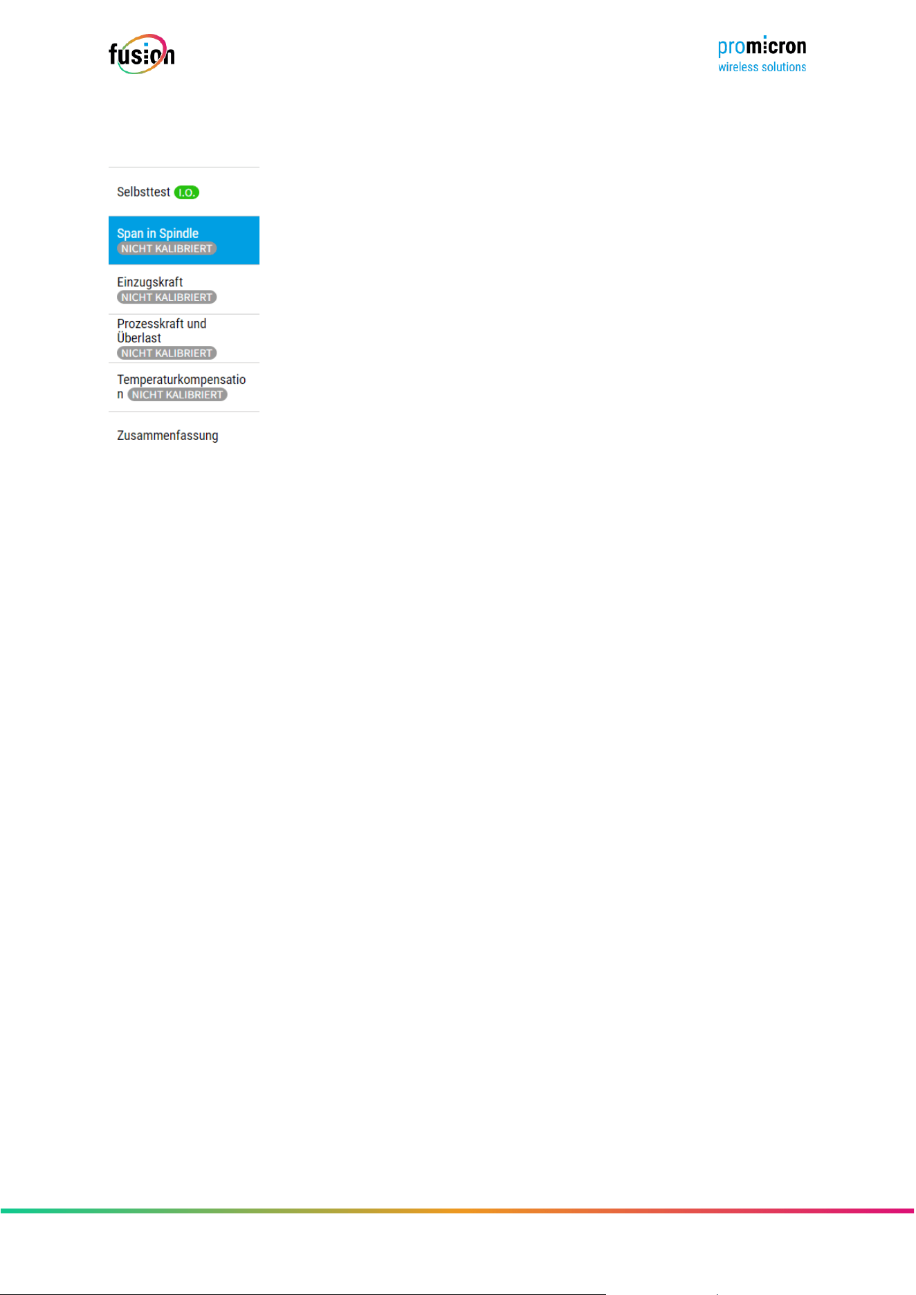
5.4.3 Chip in lockers l ............................................................................................... 51
5.4.4 pull-in force .................................................................................................... 57
5.4.5 Process force and overload ................................................................................ 59
5.4.6 Temperature compensation ................................................................................ 62
5.4.7 Summary ........................................................................................................ 65
6 Troubleshooting.................................................................................................... 66
6.1 Contact support ....................................................................................................... 66
7 glossary .............................................................................................................. 67
Seite 4 von 67
© pro-micron GmbH - Alle Rechte vorbehalten.
1 INTRODUCTION
General information
No liability is assumed for improper use or the resulting consequences.
All information and instructions in this manual refer to the development status at the time of publication.
The images used are symbolic photos. Due to possible typographical and printing errors, but also the need
for ongoing technical changes, we ask for your understanding that we cannot accept any liability for the
accuracy of the content.
Labelling
The spike® system (sensors and receiver) has a unique serial number for identication purposes, which
is attached to the outside of the housing. The serial number is also programmed into the device.
scope of application
The system is used to measure the forces and moments acting on the tool holder during machining. The
main areas of application are drilling, milling, turning, threading, grinding and reaming.

Seite 5 von 67
© pro-micron GmbH - Alle Rechte vorbehalten.
1.0 SAFETY NOTICE
Compliance statement (part 15.19)
This device complies with part 15 of the FCC Rules and to RSS of Industry Canada. Operation is subject to
the following two conditions:
1. this device may not cause harmful interference, and
2. this device must accept any interference received, including interference that may cause
undesired operation.
Le présent appareil est conforme aux CNR d'Industrie Canada applicables aux appareils radio exempts de
licence. L'exploitation est autorisée aux deux conditions suivantes : (1) l'appareil ne doit pas produire de
brouillage, et (2) l'utilisateur de l'appareil doit accepter tout brouillage radioélectrique subi, même si le
brouillage est susceptible d'en compromettre le fonctionnement.
Warning (part 15.21)
Changes or modications not expressly approved by the party responsible for compliance could void the
user’s authority to operate the equipment.
Information to the User (Part 15.105 (b))
Note: This equipment has been tested and found to comply with the limits for a Class B digital device,
pursuant to part 15 of the FCC Rules. These limits are designed to provide reasonable protection against
harmful interference in a residential installation. This equipment generates, uses and can radiate radio
frequency energy and, if not installed and used in accordance with the instructions, may cause harmful
interference to radio communications. However, there is no guarantee that interference will not occur in a
particular installation. If this equipment does cause harmful interference to radio or television reception,
which can be determined by turning the equipment off and on, the user is encouraged to try to correct the
interference by one or more of the following measures:
• Reorient or relocate the receiving antenna.
• Increase the separation between the equipment and receiver.
• Connect the equipment into an outlet on a circuit different from that to which the receiver is
connected.
• Consult the dealer or an experienced radio/TV technician for help.
This Class B digital apparatus complies with Canadian ICES-003. Cet appareil numérique de Classe B est
conforme à la norme Canadienne ICES-003.
To comply with FCC and Industry Canada RF radiation exposure limits for general population, the
antenna(s) used for this transmitter must be installed such that a minimum separation distance of 20 cm
is maintained between the radiator (antenna) and all persons at all times and must not be co-located or
operating in conjunction with any other antenna or transmitter.
Seite 6 von 67
© pro-micron GmbH - Alle Rechte vorbehalten.
1.1 OVERALL SYSTEM
1.2 PURPOSE OF THE SYSTEM
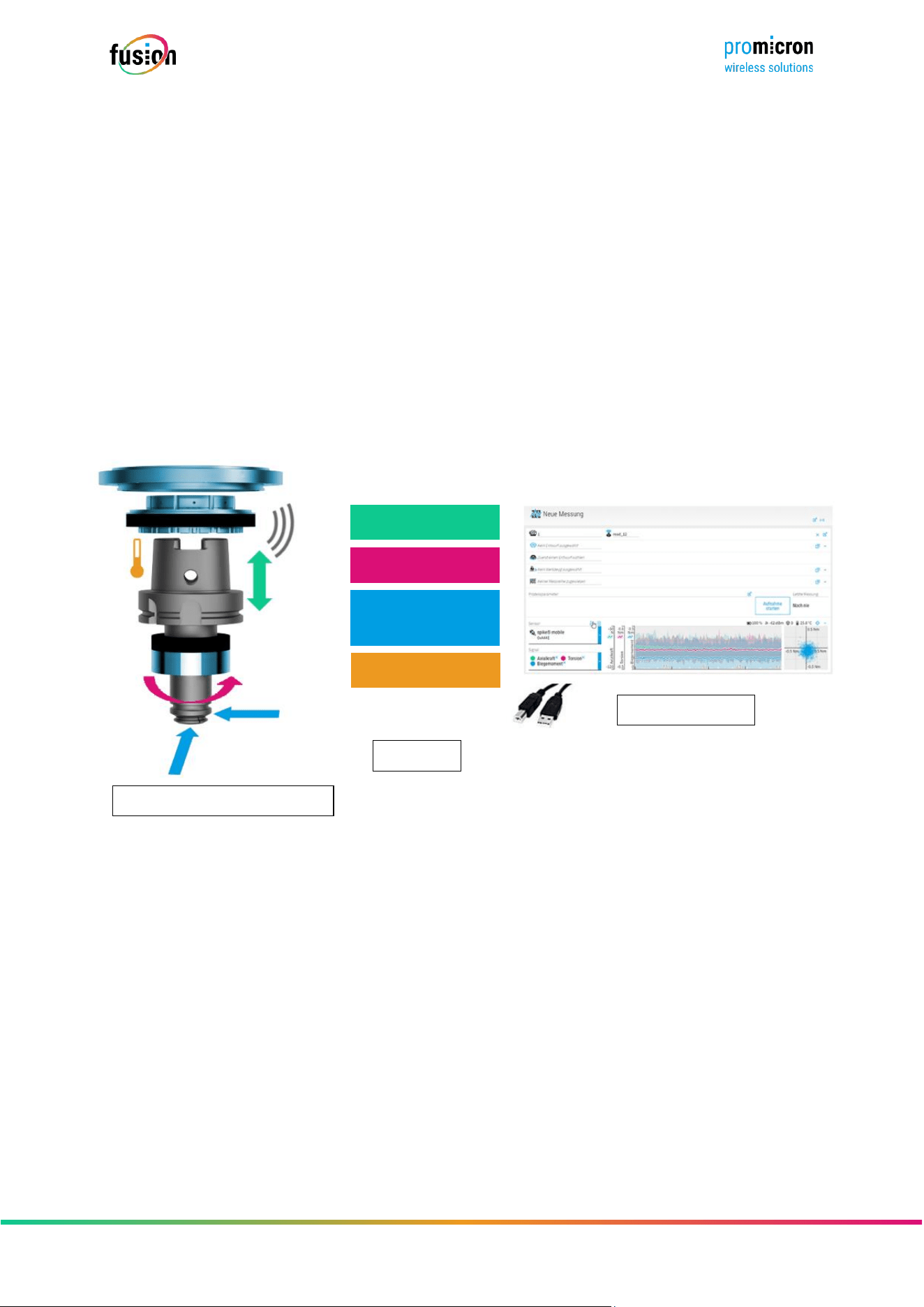
The spike® system consists of a sensory tool holder that communicates with a receiver. The fusion
software accesses the receiver’s data. The fusion software can be used to visualize the following physical
variables that act on the tool holder:
▪ Torsion moment
▪ Bending moment
▪ Axial force
▪ Sensor recording temperature
This representation enables, among other things, the following aspects:
▪ Visualization of the process forces
▪ Limit monitoring
▪ Derivation of the tool status
▪ Creating reports
1.3 TARGET GROUP
This user manual is intended for trained specialist personnel. The content of these instructions must be
made accessible to specialist personnel and implemented. The use of the spike® system is only permitted
for trained personnel.
Funk
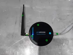
Receiver
Via USB an PC
Software fusion
Sensorischer Werkzeughalter
Axialkraft
Torsion
Biegemoment in x-
und y-Richtung
Temperatur

Seite 7 von 67
© pro-micron GmbH - Alle Rechte vorbehalten.
2 INSTALLATION
The software is installed on a PC/laptop or an industrial PC (IPC).
If the fusion software is installed on a PC/laptop, it can be used as a standalone program to manually
control a connection to the receiving device. A PC/laptop allows direct access to the user interface of the
fusion software . In addition, installation on a PC/laptop is recommended if the measurement data is
recorded with a mobile system. This variant is chosen if automated, permanent process monitoring is not
required.
fusion software on an IPC is used for permanent process monitoring within a machine .
2.1 SYSTEM REQUIREMENTS FOR PC AND IPC
The following minimum requirements apply for PC or IPC:
▪ Windows 10
▪ CPU: Intel Core i5 (10th generation)
▪ 8 GB of RAM
▪ 512GB SSD
Recommended:
▪ Windows 10
▪ CPU: Intel Core i7 (10th generation or higher)
▪ at least 16 GB of RAM
▪ 512GB SSD
▪ at least mid-range graphics card
If you have any questions about the system conguration for the fusion software, please contact promicron
support.
Seite 8 von 67
© pro-micron GmbH - Alle Rechte vorbehalten.
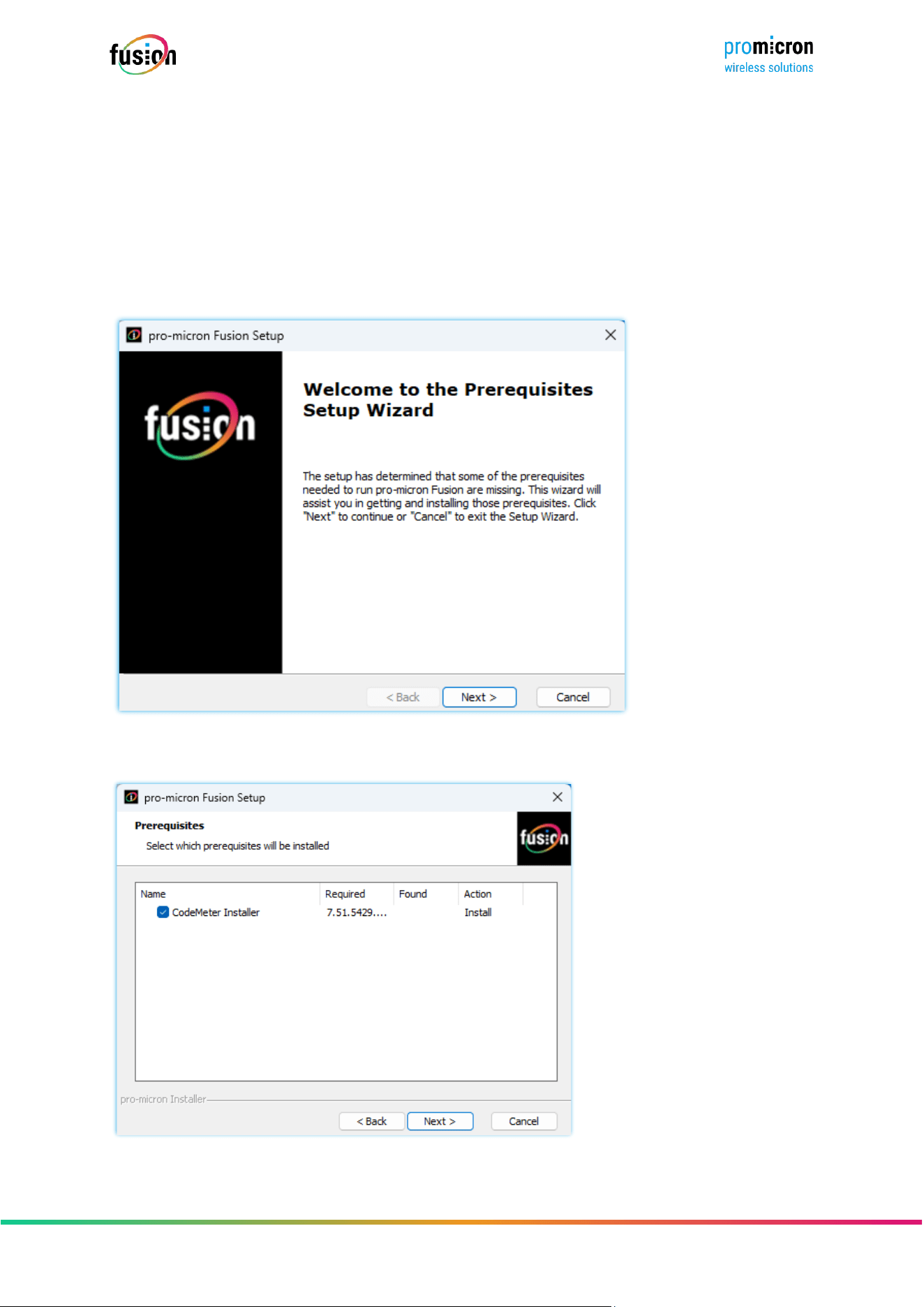
2.2 INSTALLATION PROCESS
fusion _[version number].exe” is located on the supplied data carrier . Admin rights are required to install
the fusion software.
➔ Start “ fusion setup.exe”
➔ Conrm Windows security warning with “Yes”.
➔ Installation wizard opens
➔ Select “Next”
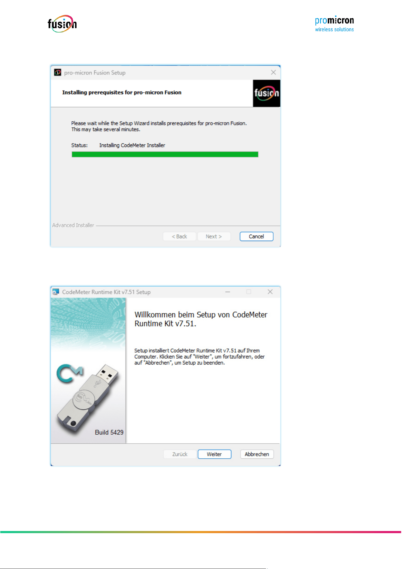
➔ Select “Next” to install CodeMeter (license checking software)
Seite 9 von 67
© pro-micron GmbH - Alle Rechte vorbehalten.
2.2.1 INSTALLING CODEMETER
➔ Wait until the next request window appears
➔ Select “Next”
Seite 10 von 67
© pro-micron GmbH - Alle Rechte vorbehalten.
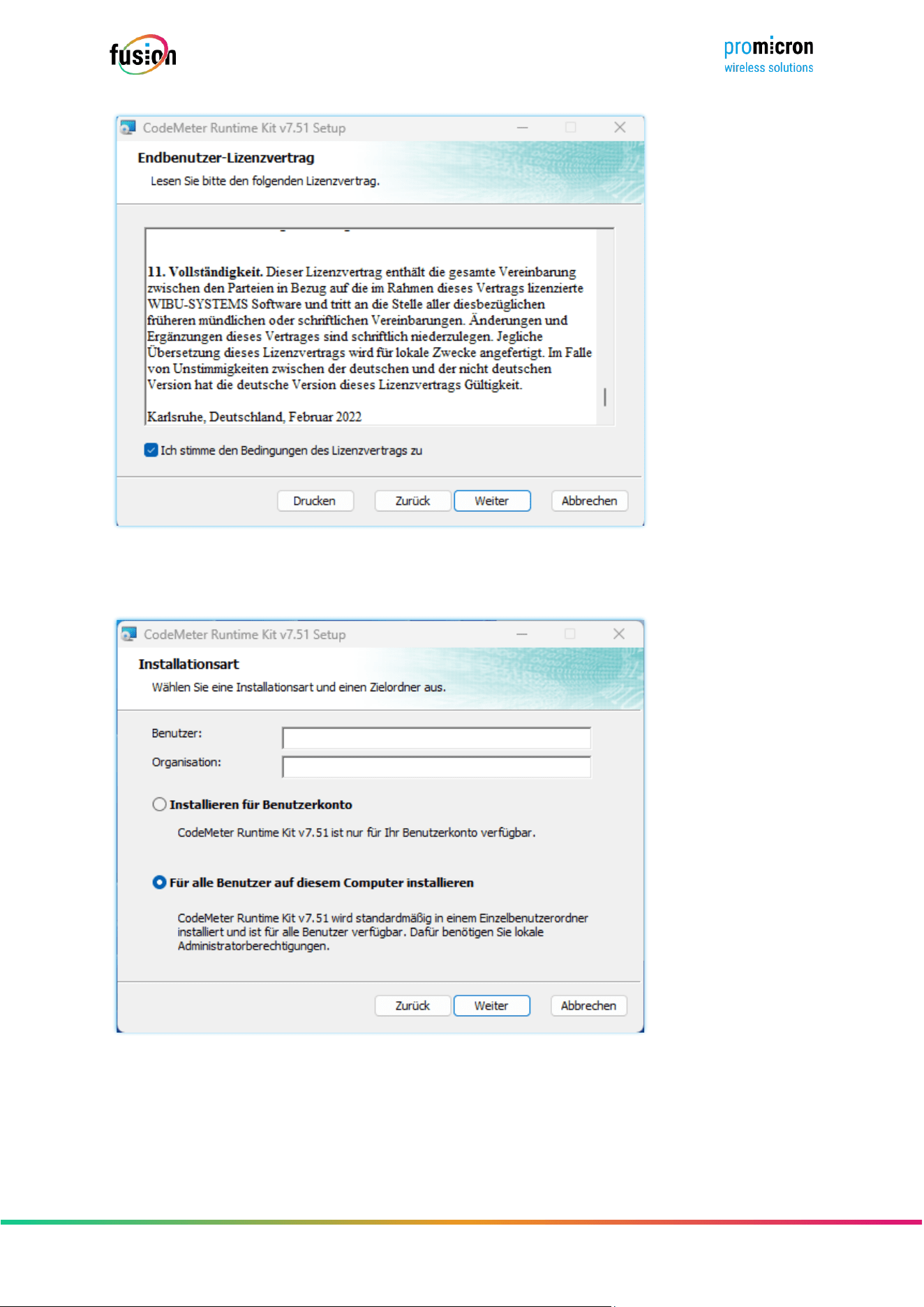
➔ Agree to license terms
➔ Select “Next”
➔ Select “Next”
Seite 11 von 67
© pro-micron GmbH - Alle Rechte vorbehalten.
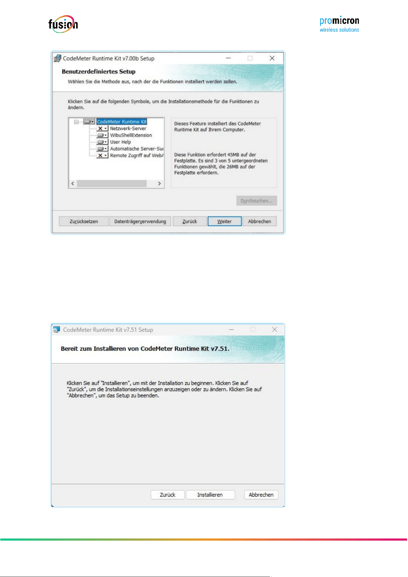
Features recommended for Custom Setup:
▪ WibuShellExtension
▪ User Help
▪ Automatic server search
➔ Select “Next”
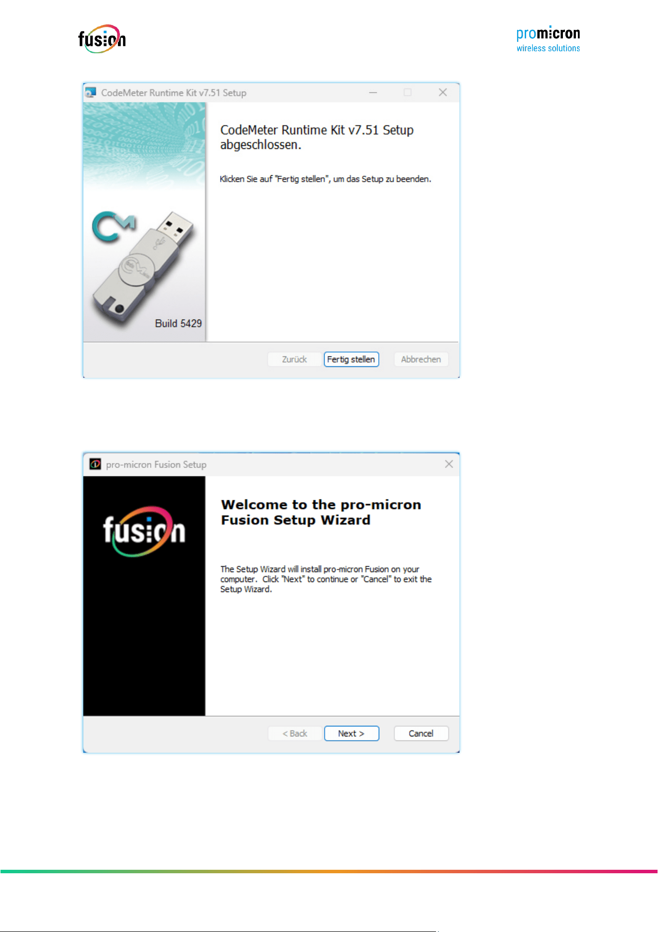
➔ Select “Install”
Seite 12 von 67
© pro-micron GmbH - Alle Rechte vorbehalten.
➔ “Finish” selection
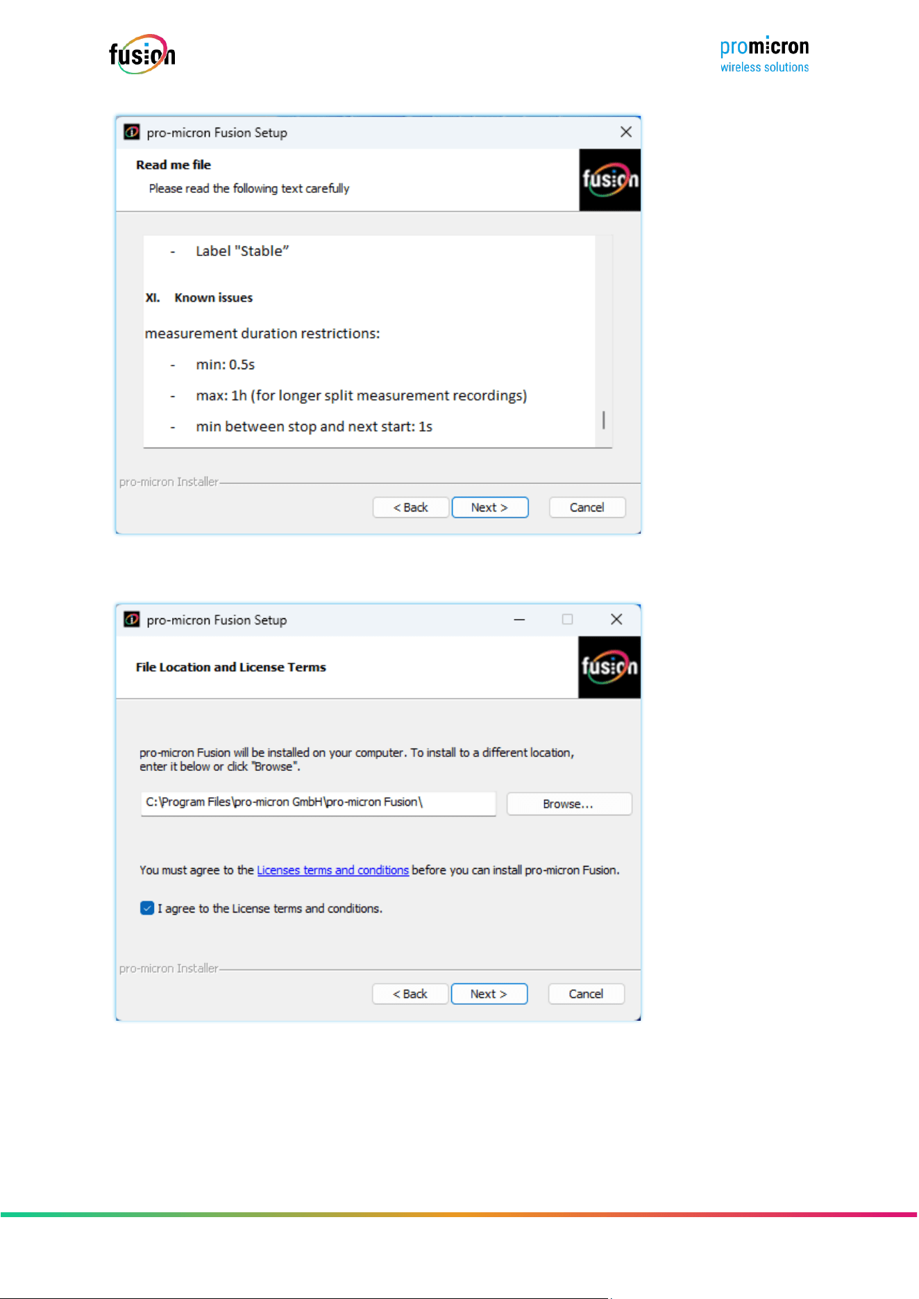
2.2.2 INSTALLATION OF FUSION
➔ Selection “Next”
Seite 13 von 67
© pro-micron GmbH - Alle Rechte vorbehalten.
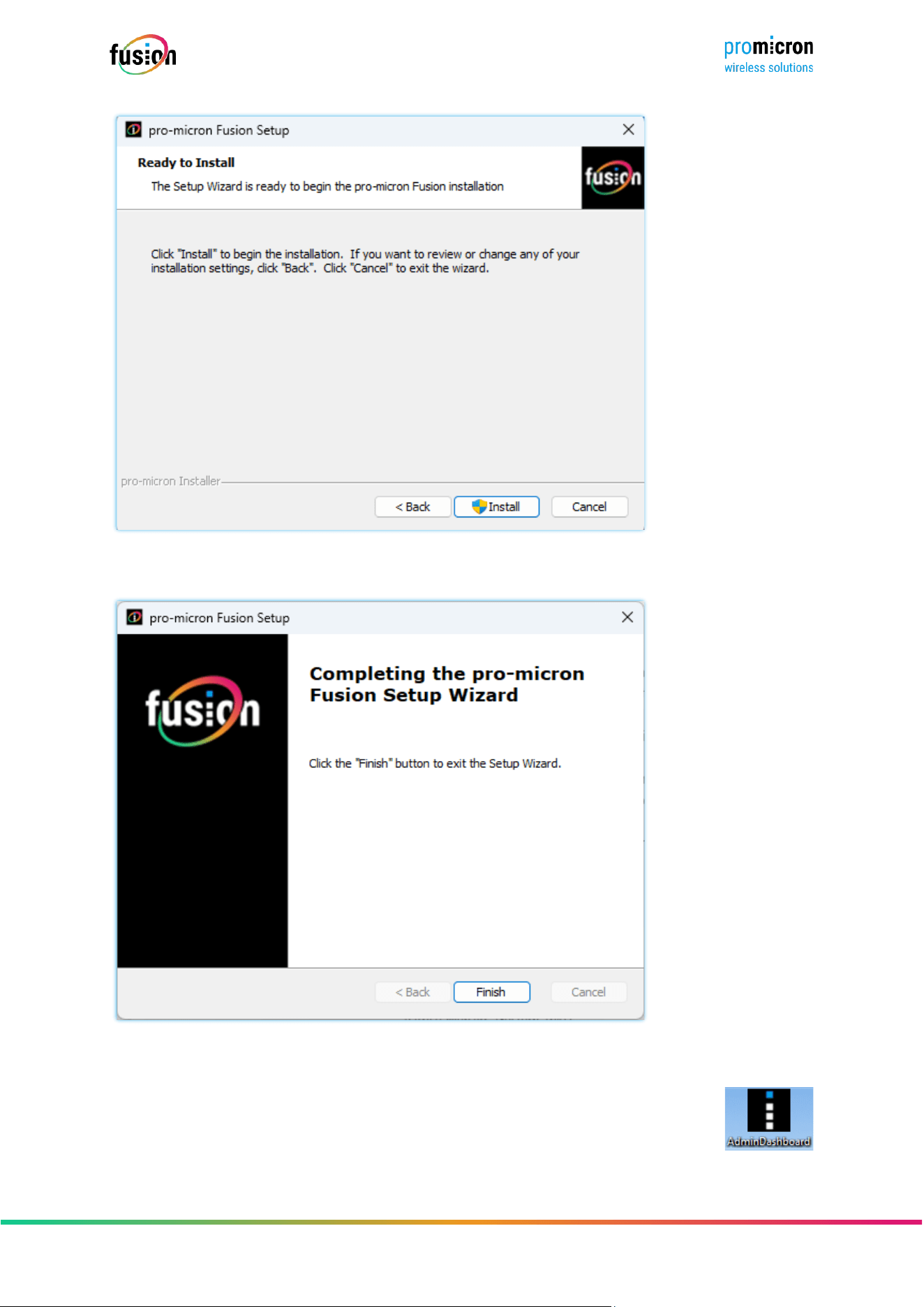
➔ Selection “Next”
➔ Select installation folder
➔ Agree to license terms
➔ Selection “Next”
Seite 14 von 67
© pro-micron GmbH - Alle Rechte vorbehalten.
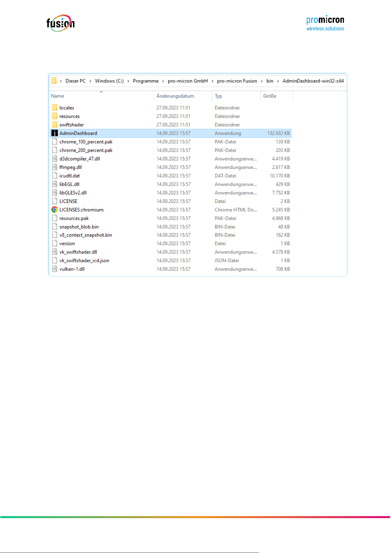
➔ Select “ Install ”
➔ “Finish” selection
There is now a shortcut to the admin dashboard on the desktop.
Seite 15 von 67
© pro-micron GmbH - Alle Rechte vorbehalten.
2.3 MAIN PROGRAM LOCATION
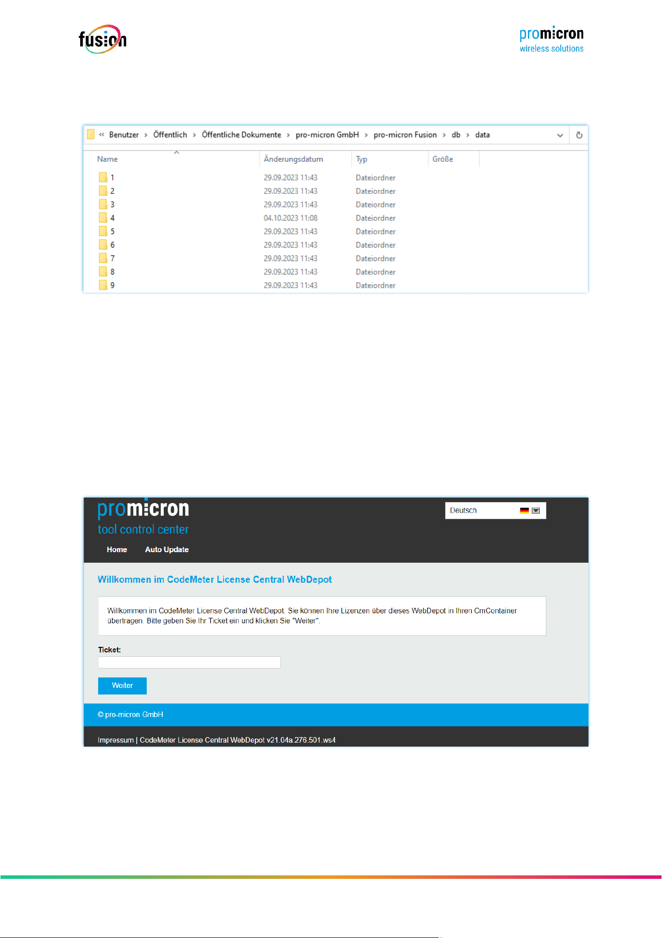
The main program “ AdminDashboard ” of the fusion software can be found by default at the following
path:
C:\Program Files\pro- micron GmbH\pro- micron Fusion\bin\AdminDashboard-win32-x64
or
C:\Programs\pro-micron GmbH\pro- micron Fusion\bin\AdminDashboard-win32-x64
Seite 16 von 67
© pro-micron GmbH - Alle Rechte vorbehalten.
2.4 STORAGE LOCATION OF MEASUREMENT DATA
The folder for the saved measurement data can be found at the following path:
C:\Users\Public\Documents\pro-micron GmbH\pro- micron Fusion
or
C:\Users\Public\Public Documents\pro- micron GmbH\pro- micron
2.5 LICENSING AND ACTIVATION
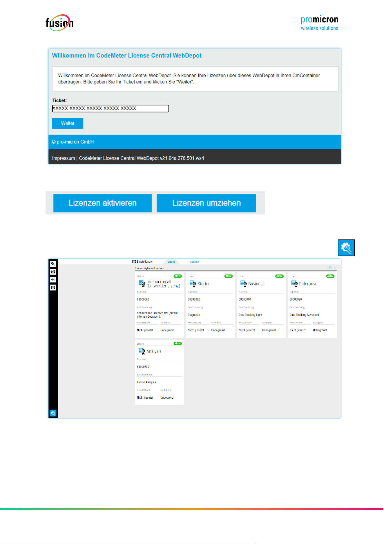
The license can be activated via the following website:
https://iot.pro-micron.de/index.php
➔ Enter ticket number in the input eld
Seite 17 von 67
© pro-micron GmbH - Alle Rechte vorbehalten.
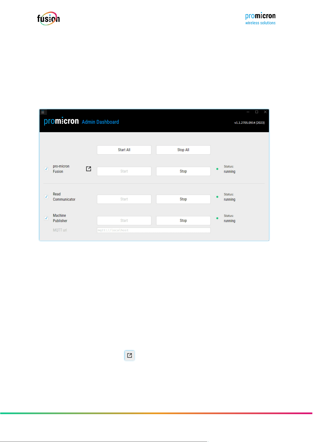
➔ Select “Next”
➔ Select “Activate licenses”
The activated licenses or the status of the licenses can later be viewed in the “Settings” tab.

Seite 18 von 67
© pro-micron GmbH - Alle Rechte vorbehalten.
License overview:
▪ Starter : for easy measurement data recording and viewing of individual measurement les using tags
and the database
▪ Business : with machine connection; Software access to machine data (e.g. axis data and tool data)
via a machine interface (pm-connector)
▪ Enterprise : full functionality
▪ Analysis: for individual measurement data analysis and for overlaying multiple measurement data
streams
Seite 19 von 67
© pro-micron GmbH - Alle Rechte vorbehalten.
3 MAIN FUNCTIONS
3.1 ADMIN DASHBOARD
The admin dashboard is started by double-clicking the icon on the desktop.
Alternatively, it can be opened via Explorer if no shortcut to the admin dashboard has been created:
C:\Program Files\pro- micron GmbH\pro- micron Fusion\bin\AdminDashboard-win32-x64
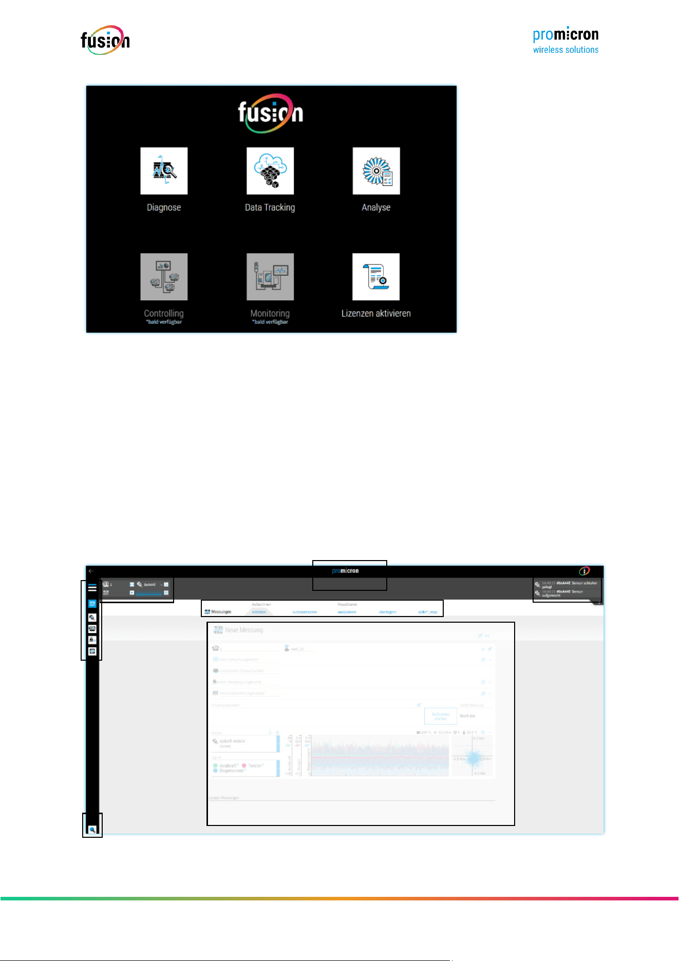
Three components are centrally controlled via the admin dashboard:
▪ pro- micron Fusion: the actual software, executed as an application
▪ Read Communicator: for communication between the PC/laptop/IPC and the receiving unit
▪ Machine Publisher: for communication between the PC/laptop/IPC and the machine via the pm-
connector
It is recommended to select (tick) the components that correspond to the existing overall structure and
then start the software including communication interfaces together via “Start All”. After the start, the
status of the relevant components changes to “ running ”. The fusion software dashboard opens.
Alternatively, the components can be started individually.
Clicking on this icon will directly start the fusion software and open the fusion dashboard.
Seite 20 von 67
© pro-micron GmbH - Alle Rechte vorbehalten.
via the fusion dashboard, depending on the user's focus. The respective home screen opens by clicking
on the corresponding icon.
▪ Create diagnostic →measurements→create
▪ Data tracking→ Measurements → automate
▪ Analysis →Analyze measurements→ analyze
▪ Activate licenses →Settings →Licenses
3.2 SCREEN DISPLAY
3.2.1 OVERVIEW
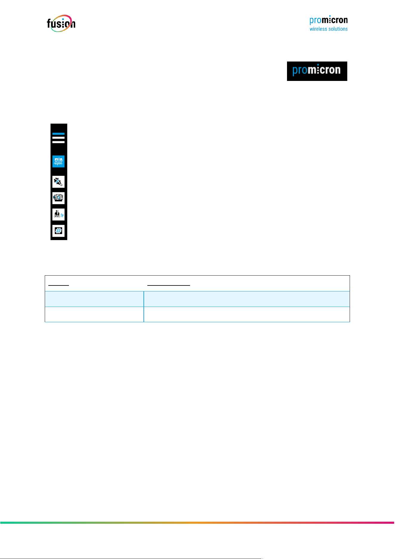
Menü
Funktionen
Live-Daten
Historie
Datenanzeige
Link zu fusion-Dashboard
Einstellungen
Seite 21 von 67
© pro-micron GmbH - Alle Rechte vorbehalten.
3.2.2 LINK TO FUSION DASHBOARD
The fusion dashboard can be selected from any level of the software by -clicking
on the pro micron logo.
3.2.3 MENU
Any other functionality can be achieved from any home screen.
Measurements
Sensors
machinery
Tools
tags
3.2.4 SETTINGS
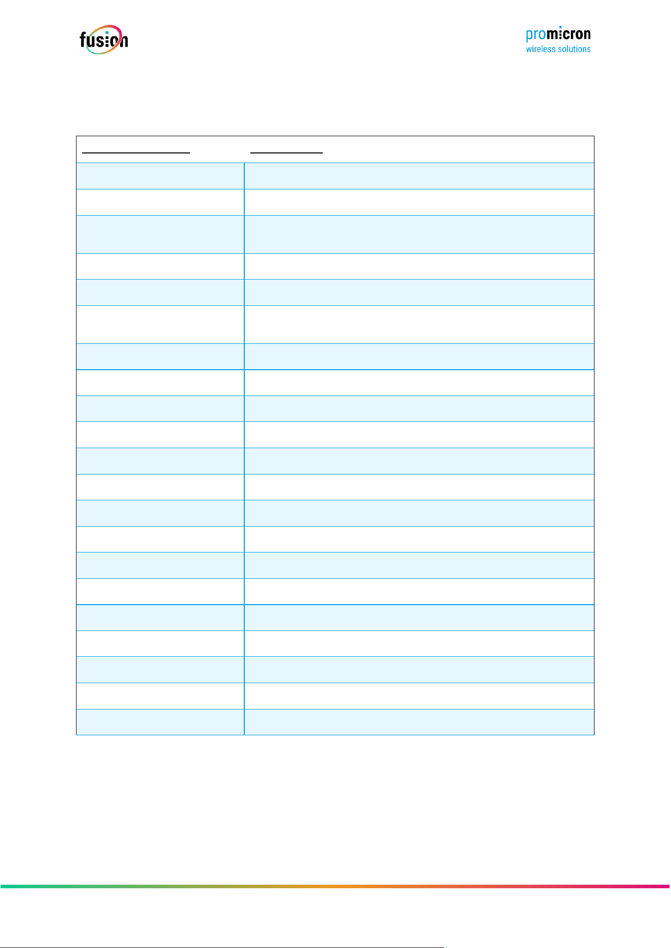
menu
Description
License
Overview of available licenses
Contact
Contact details for pro- micron support
Seite 22 von 67
© pro-micron GmbH - Alle Rechte vorbehalten.
3.2.5 FEATURES
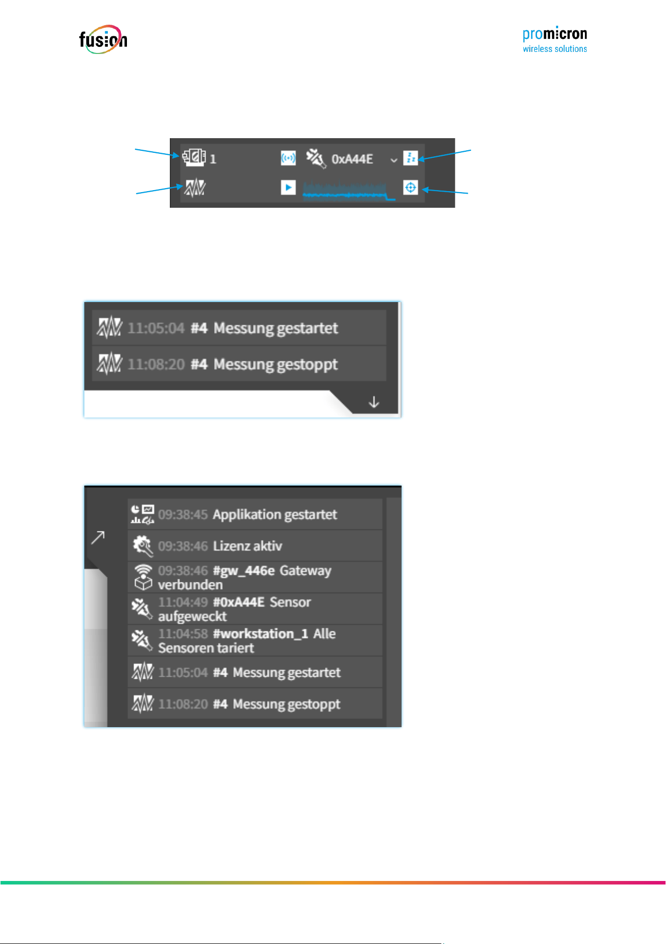
Different functionalities are assigned to the different menu objects.
Function menu→
Description
Measurements
Visualization of measurements
Create measurements→
Create and stream measurements
Measurements→ automate
Creating automated measurements (e.g. eldbus, NC trigger or M
commands)
Analyze measurements→
Analyzing measurements that have already been created
Measurements→ overlay
Overlay multiple measurements for comparison
Measurements→ spike_map
Visualized representation of the process ow including the force -
inuences
Sensors
Conguration of the sensors
Sensors→ create
Representing the registered receiving unit and sensor
Sensors→ edit
Editing the parameter list
Test sensors→
Carrying out self-tests for the sensor and receiving unit
machinery
Conguration of the machine used
machinery→ create
Setting the machine parameters
machinery→ edit
Editing the machine's parameter list
Tools
Conguration of the tools used
Create tools→
Creating new tools
Tools→ edit
Editing already created tools
tags
Conguration of tags and labels
tags→ create
Creating new tags
tags→ edit
Editing already created tags
labels→ create
Creating new labels
labels→ edit
Editing already created labels
Seite 23 von 67
© pro-micron GmbH - Alle Rechte vorbehalten.
3.2.6 LIVE DATA
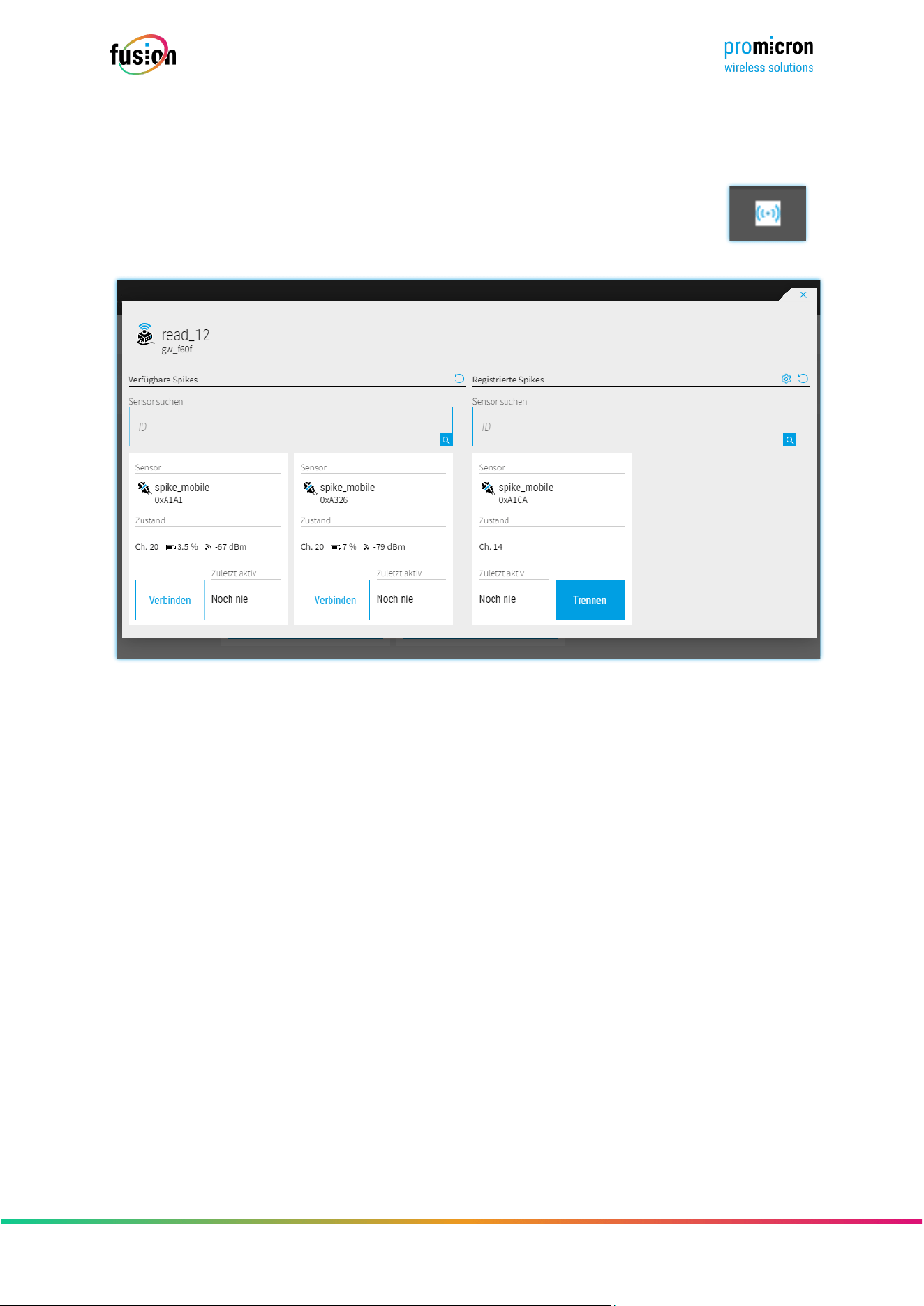
The live data provides an overview of the current status of the entire system.
Machine sensor
Measurement stream
3.2.7 HISTORY
The history lists information about activities, status messages and error messages.
The history display is expanded by clicking on the arrow on the right and collapsed again by clicking on
the left arrow.
3.2.8 ADVERTISEMENT
The representations in the display depend on the selected function.
Seite 24 von 67
© pro-micron GmbH - Alle Rechte vorbehalten.
4 STEP-BY-STEP INSTRUCTIONS
4.1 CONNECT A SENSOR
In the Sensors > Create menu, the send icon must be clicked, then a list opens with all
sensors that are in the area and recognized by the system. Alternatively, quick access is
possible via the send icon in the live data area. This list updates automatically a few
seconds after the window opens.
The available spikes area (1) lists the sensors that are recognized by the receiving system (2) and have
not yet been registered. To register a sensor, “Connect” (3) must be selected. A connected sensor is listed
under Registered Spikes (4). The receiving system can now exchange data with this sensor. A registered
sensor can be selected in the main menu and in the submenus.
If a sensor is disconnected again (5), it no longer sends data to the receiving system and is listed again
under Available Spikes. Available sensors cannot be selected in the main menu or in submenus.
If a sensor is in the area but is not listed under Available Spikes, the power supply is not sucient to send
a radio signal. The sensor must then be charged rst.
(1)
(4)
(3)
(2)
(5)
Seite 25 von 67
© pro-micron GmbH - Alle Rechte vorbehalten.
4.2 START A MEASUREMENT
4.2.1 START A MEASUREMENT WITH SPIKE®_MOBILE
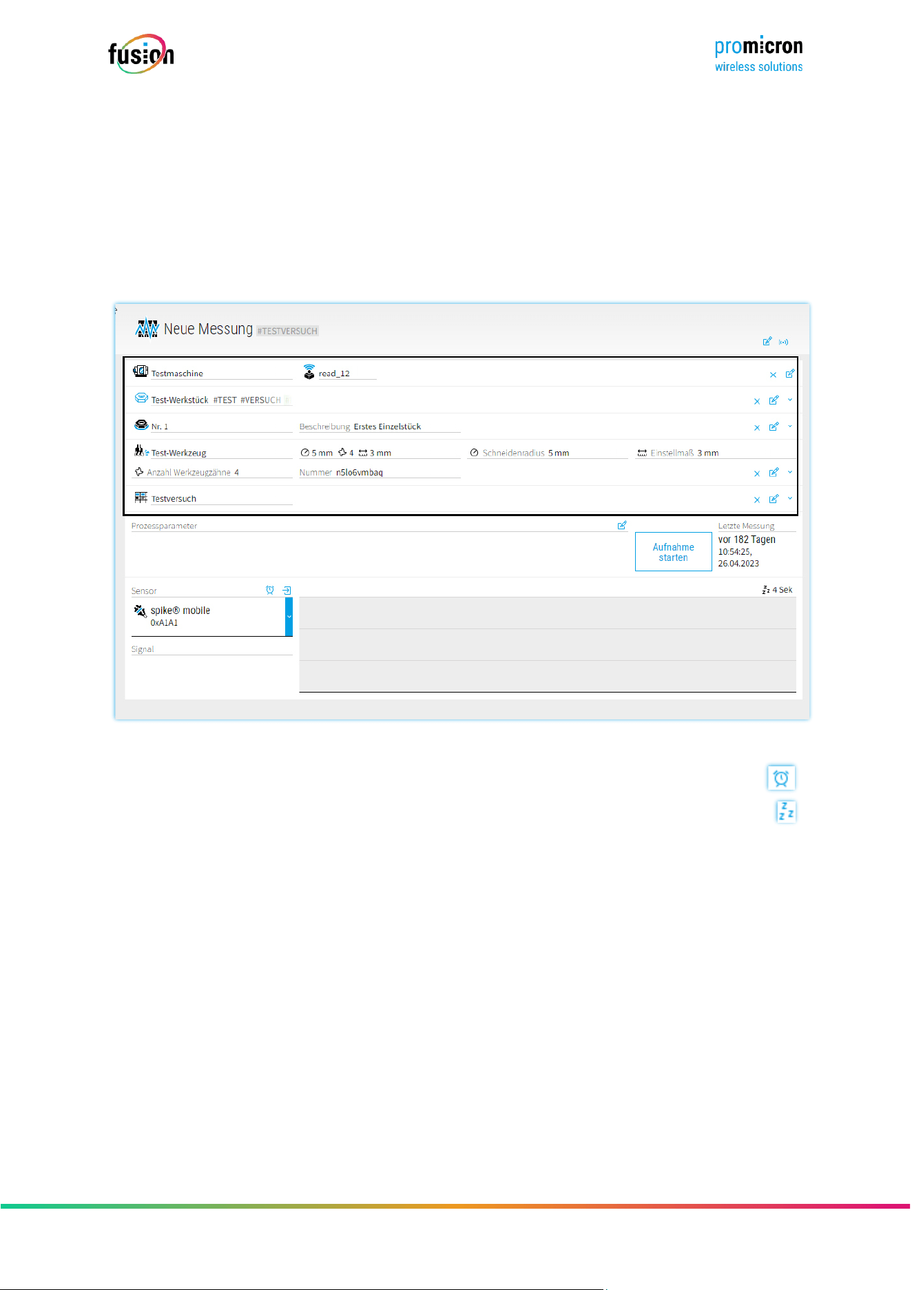
If a sensor is registered, the software can capture and record its measured values. In the Measurements
menu under the Create function, all essential information (1) is rst recorded that facilitates the
subsequent traceability of the measurements, for example the processing machine, the process
parameters and the tool. Tags are also available; their use is explained in Section 0.
The registered spikes are available for selection in a list (2). The desired spike is selected and
woken up from sleep mode by clicking on the alarm clock icon. This activates the data stream,
the current measured values are displayed in the diagram (3). The alarm clock icon changes to the
“sleep” icon. When not in use, the sensor can be put back into energy saving mode by clicking on
the “sleep” symbol.
(1)
(2)
(3)
Seite 26 von 67
© pro-micron GmbH - Alle Rechte vorbehalten.
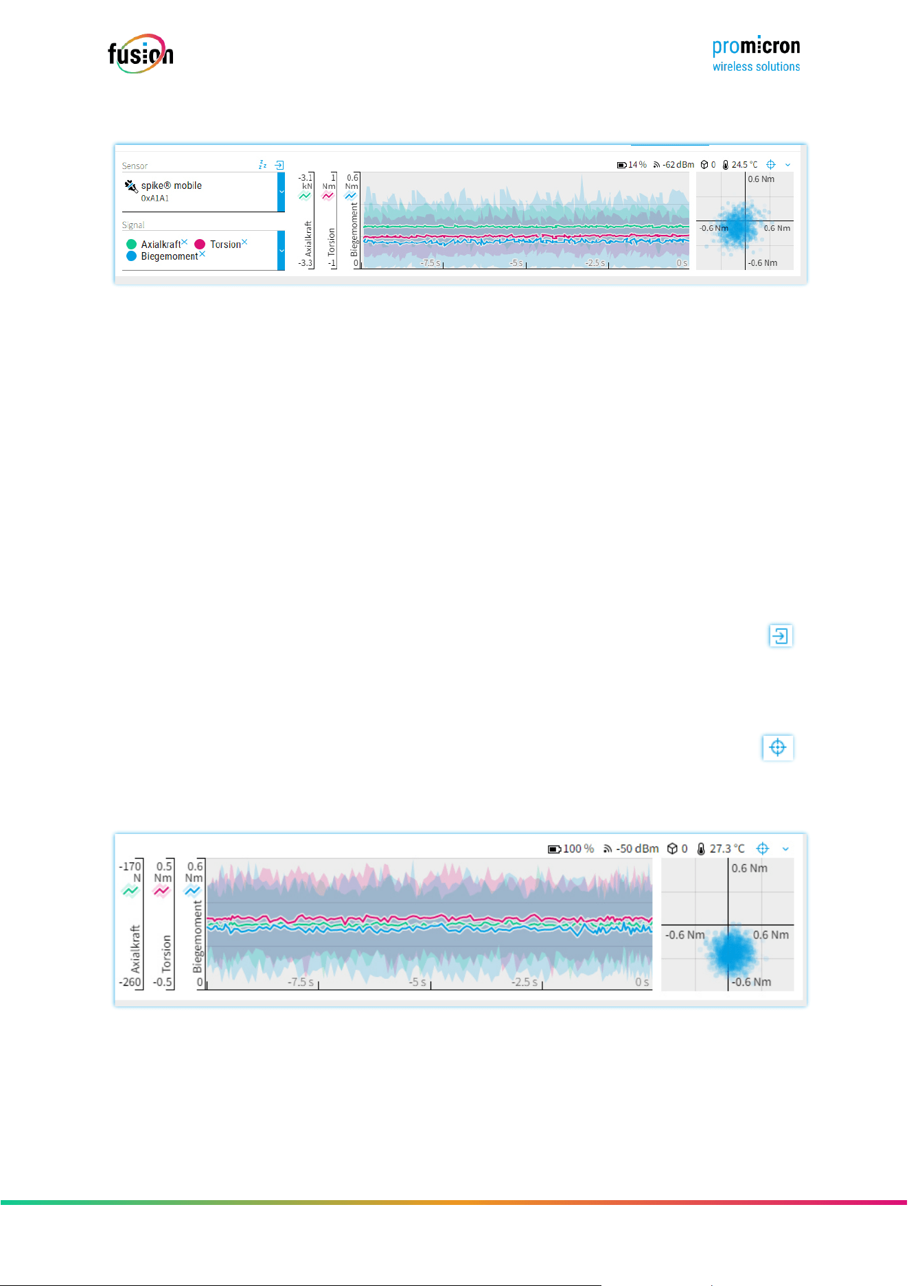
If the data stream is active, the data that the sensor measures and transmits is displayed. Depending on
the sensor, the bending moment, torsion and axial force are shown in the diagram. For each of these
variables, the values are continuously aggregated and displayed as lines (2). The representation of the
spike_polar (3) represents the measured bending moment in the coordinate system.
The data stream transmits further information about the sensor, which is displayed:
• current battery status
• RSSI value (as a measure of the strength of the received signal in wireless communication -
systems; a lower value indicates greater signal strength, while a higher value indicates lower
signal strength)
• Packet error rate (number of incorrect or not transmitted data packets in relation to the total
number of data packets sent)
• Sensor temperature.
If you want to check or adjust the settings of the selected registered sensor, you can access the
parameter list of the selected sensor using the “Access” icon (4). Details on this follow in Section
5.
If the tool is not engaged, there are no forces acting; the measurement data shows the background
noise of the sensor. This point cloud should lie at the origin of the coordinate system, but it can
be shifted from the zero point due to physical effects. By digitally taring by clicking on the
crosshair icon, the basic deviation of the bending moment in the x-direction and y-direction is corrected to
zero .
(1)
(2)
(3)
(4)
Seite 27 von 67
© pro-micron GmbH - Alle Rechte vorbehalten.
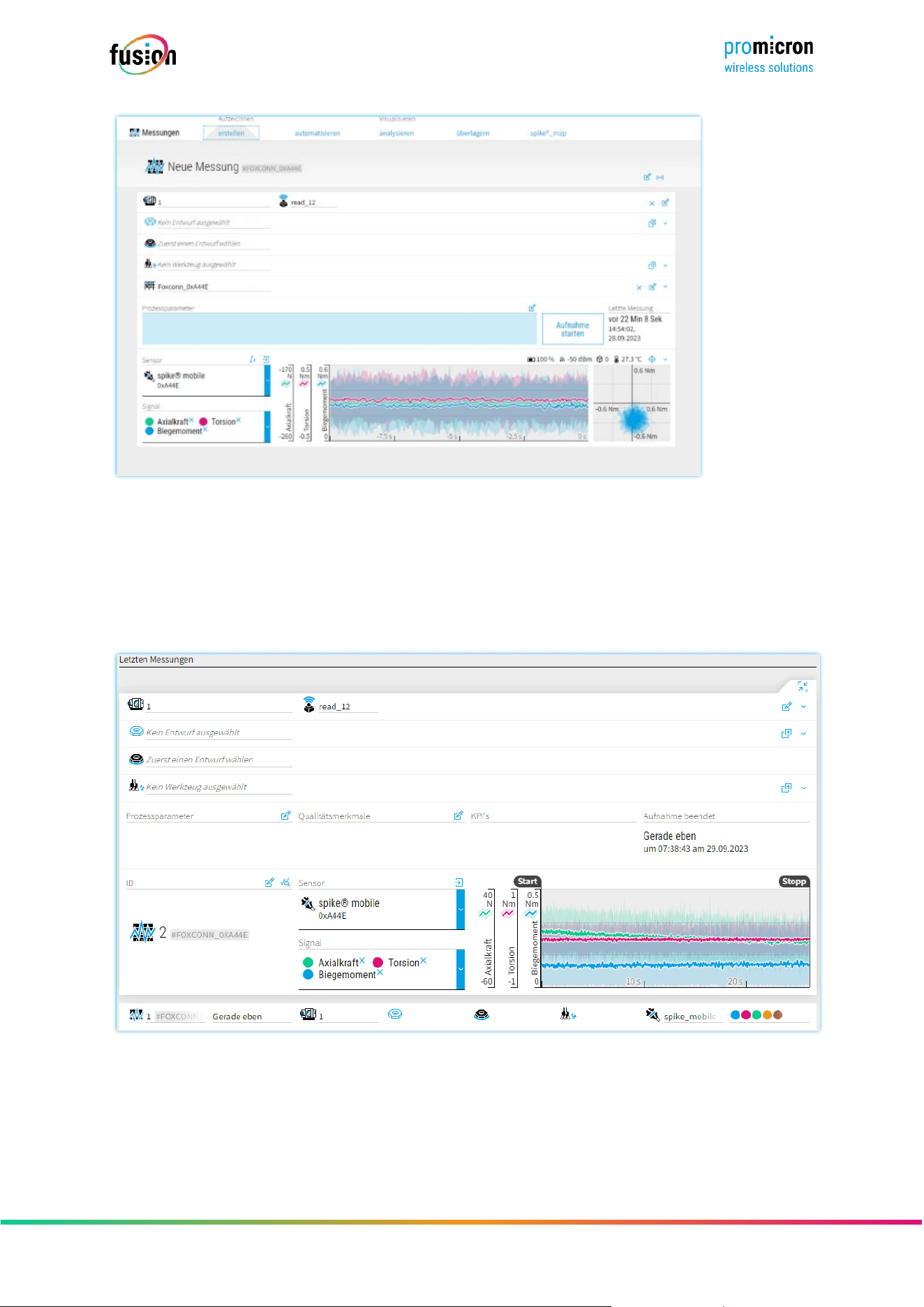
In order to start a measurement, you must click on “Start recording” (1).
After a measurement has been started, measured values are recorded. Individual measurements can be
assigned to measurement series.
The last saved measurements are shown below the display of the current sensor data. The details become
visible after the line of the corresponding measurement is expanded by clicking. Further information about
the measurement can be entered manually here.
(1)
Seite 28 von 67
© pro-micron GmbH - Alle Rechte vorbehalten.
4.2.2 START A MEASUREMENT WITH SPIKE_INSPINDLE
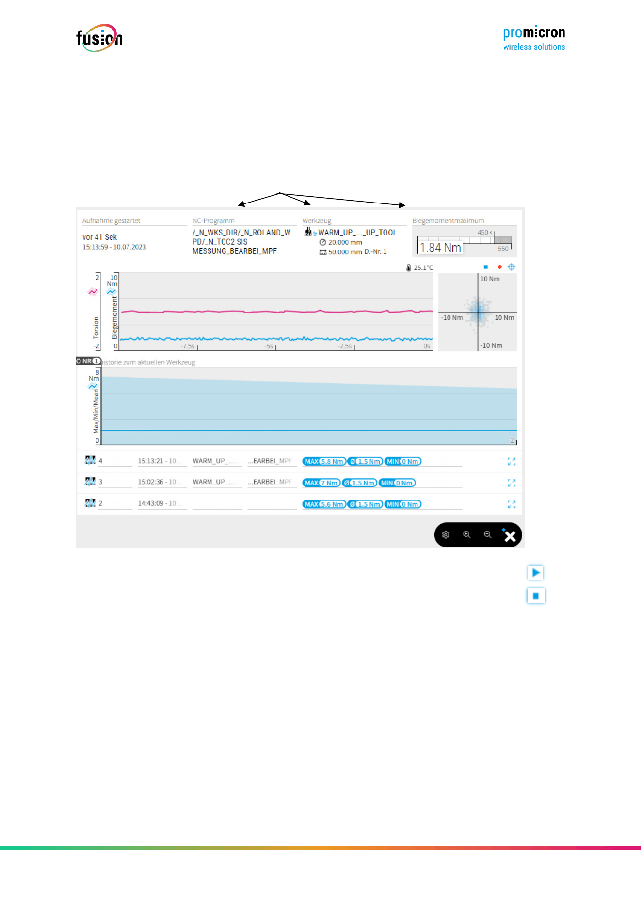
With spike_InSpindle systems, a lot of machine information can be transferred to the software via a so-
called pm_connector . Such process parameters are automatically linked to the respective measurements.
This includes the current NC program, the tool and the maximum bending moment that is stored in the
machine.
The measurement can be started by clicking on the play button above the point cloud, and the
measurement can be stopped by clicking on the stop button.
(1)
(2)
Seite 29 von 67
© pro-micron GmbH - Alle Rechte vorbehalten.
4.3 ANALYZE A MEASUREMENT
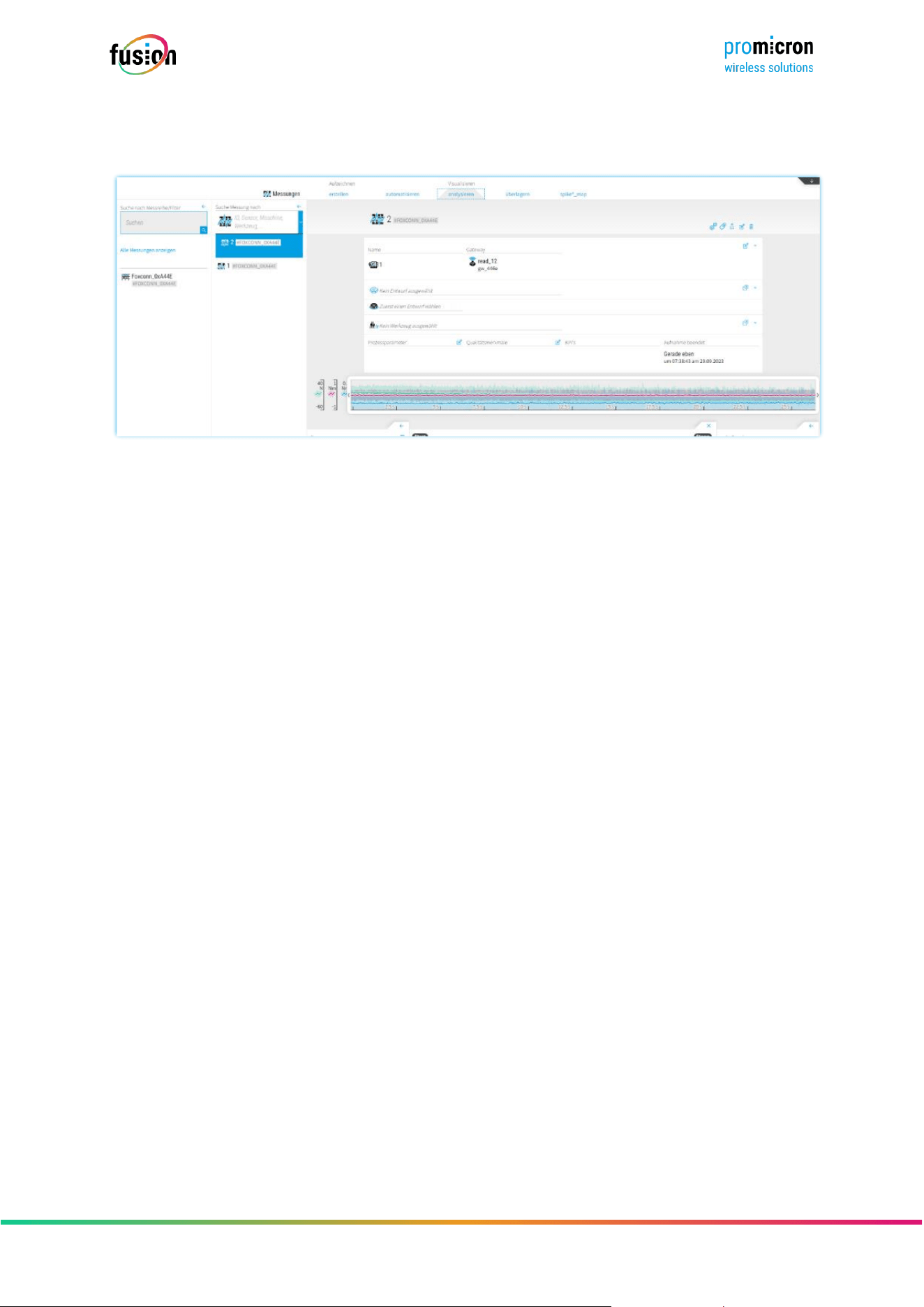
Main view:
(1) The desired series of measurements is selected using a specic component or lter.
(2) Individual measurements are selected from this series of measurements.
(3) The tool and process parameters of the selected measurement are clearly displayed.
(4) The data stream is displayed clearly or in detail when scrolling further down.
(1)
(2)
(3)
(4)
Seite 30 von 67
© pro-micron GmbH - Alle Rechte vorbehalten.
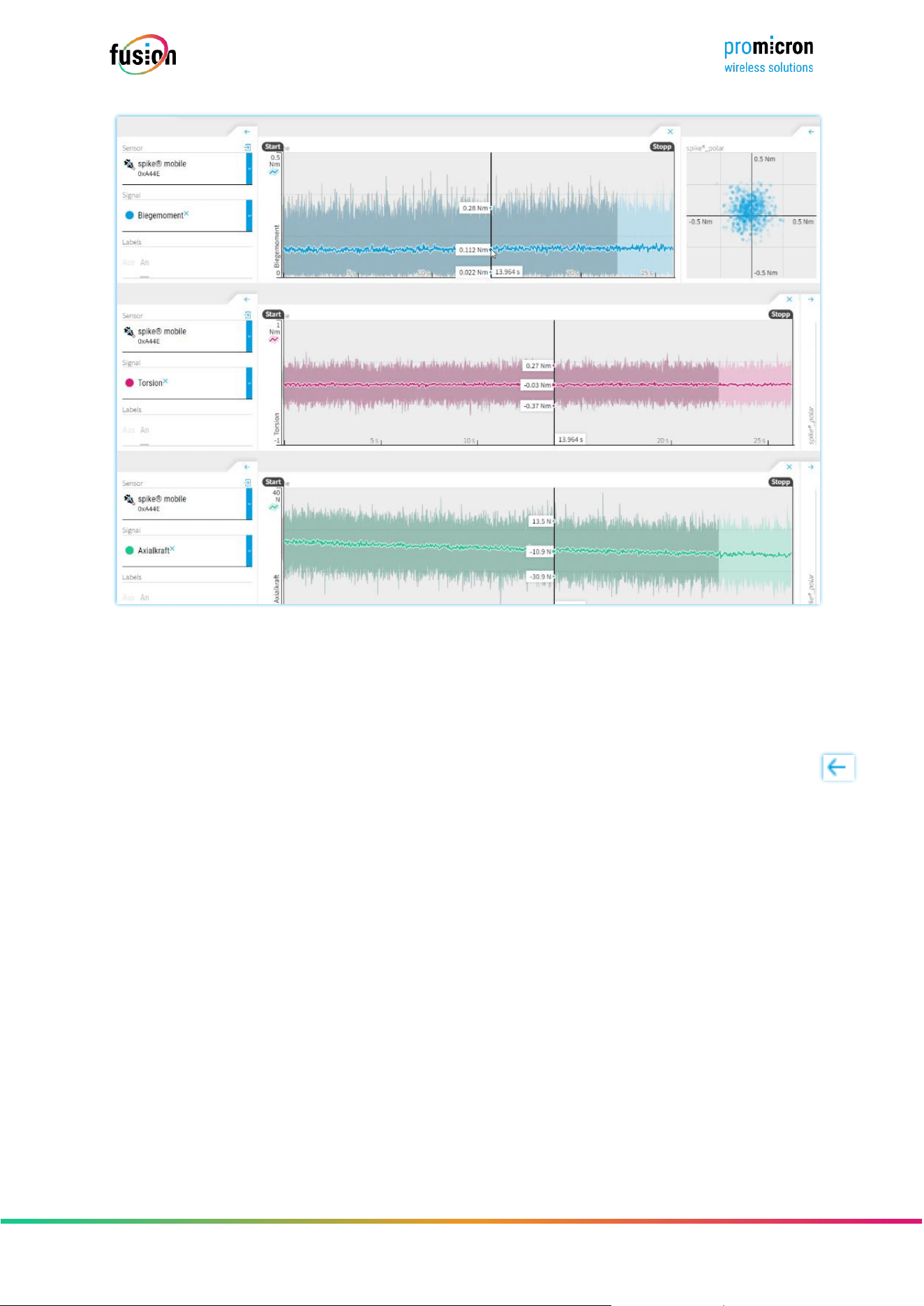
(1) The different sensors with which the measurement was recorded are selected.
(2) The different signals can be displayed selected.
(3) The black line shows the measurement data at a specic point in time.
(4) By clicking on the arrow on the right, the spike®_polar for this selected time can be displayed.
(1)
(2)
(3)
(4)
Seite 31 von 67
© pro-micron GmbH - Alle Rechte vorbehalten.
4.4 AUTOMATE A MEASUREMENT
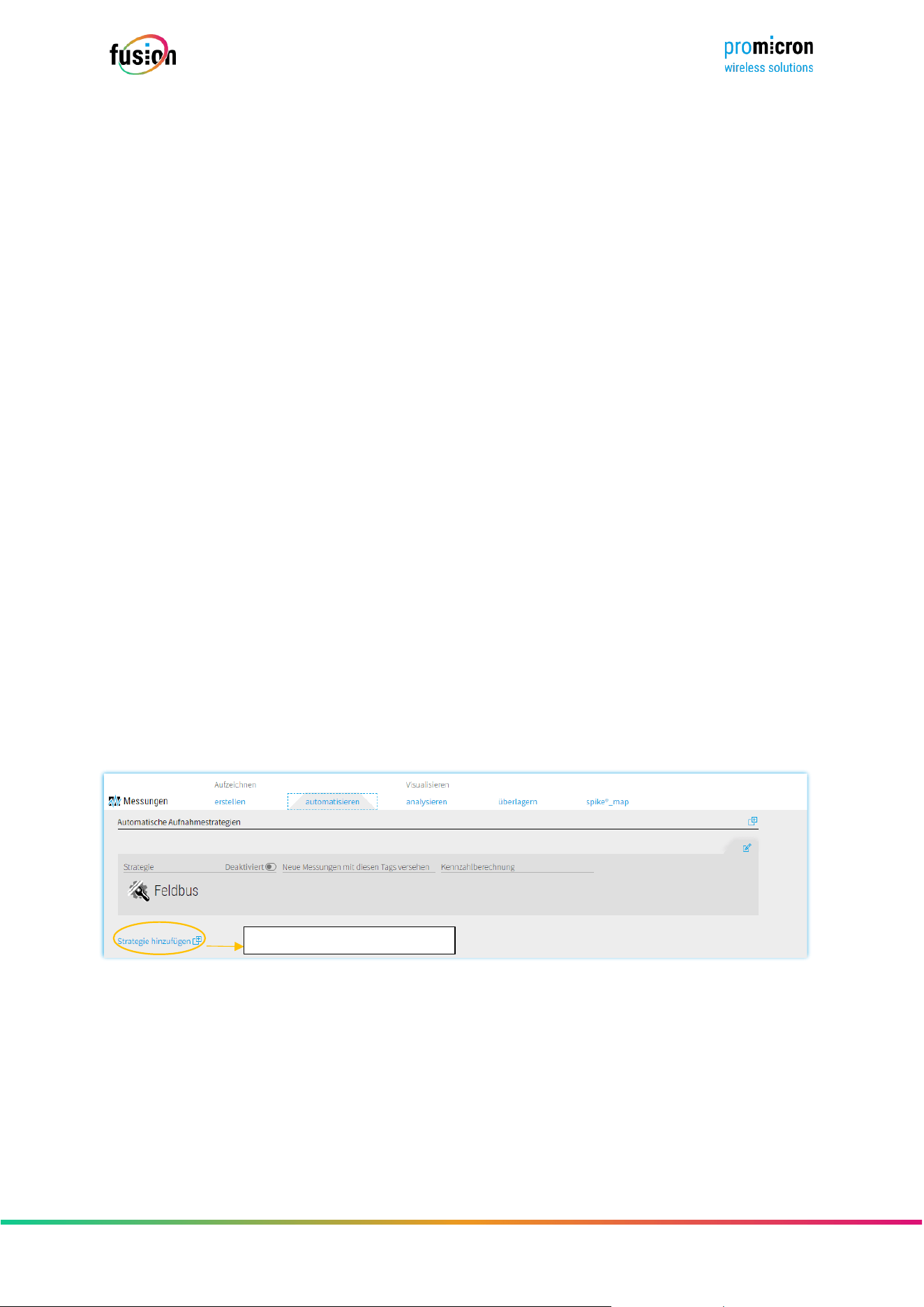
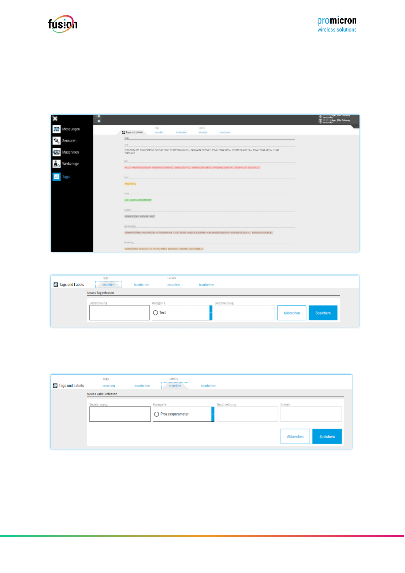
You can select from various recording strategies under Measurements > Automate.
choose between force, NC, M command and eldbus (M commands sent via Probus ). The
parameterization of the respective strategy takes place in the relevant columns. Multiple strategies can
be selected for different application areas using “Add strategy”. The settings are applied by saving.
The rst recording strategy is defaulted to eldbus and cannot be changed. Fieldbus communication can
be activated by clicking on the virtual switch.
If you want to use a different strategy, you must activate it via “Add strategy”. The eldbus strategy should
be deactivated in this case.
4.4.1 FORCE COMMAND TRIGGER
With a force trigger, a reaction is triggered when a limit value for a physical quantity or force is exceeded.
This signal can then be used to start a measurement. The trigger is typically placed at a location where
force is to be measured, such as a process step to be monitored. As soon as the predened force is
reached or exceeded, the signal is triggered and the appropriate measures are taken, for example a
measurement is started.
Use the button to add a new strategy
Seite 32 von 67
© pro-micron GmbH - Alle Rechte vorbehalten.
4.4.2 NC BLOCK TRIGGER
An NC set trigger is a mechanism that triggers a signal based on a specic set of numerical control
commands (NC set). An NC block contains instructions for controlling the movements and actions of the
machine, such as the positioning of the tool or the speed of machining. The trigger is used in the NC block
to mark the start or end of a specic section. As soon as the predened section has been processed, the
signal is triggered and the machine carries out the corresponding actions (e.g. tare, wake up, put to sleep,
start and stop measurement). In order to automate the system for NC blocks, the pm-connector is required
as an interface between Fusion and the machine.
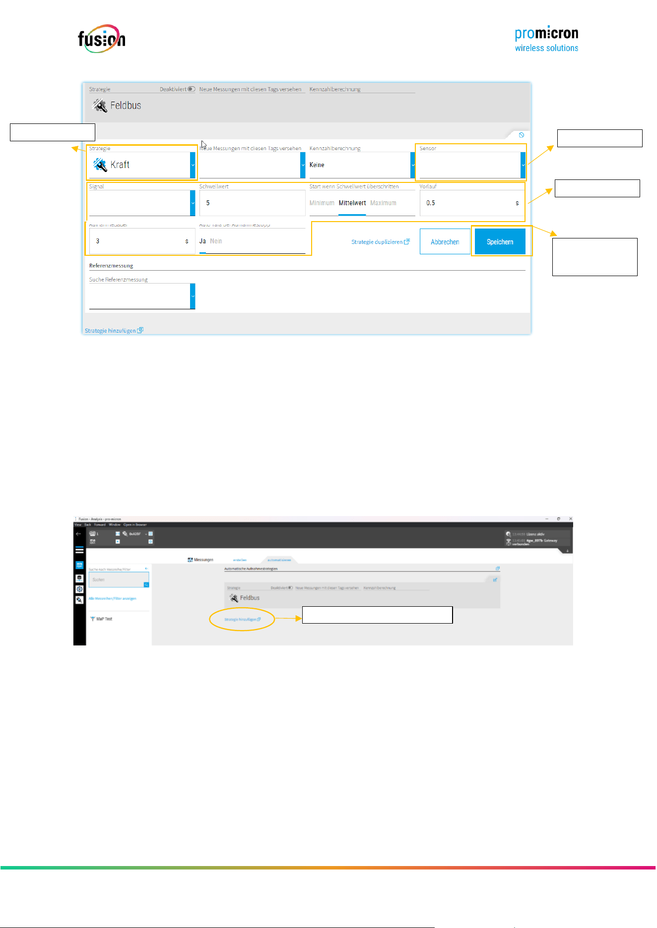
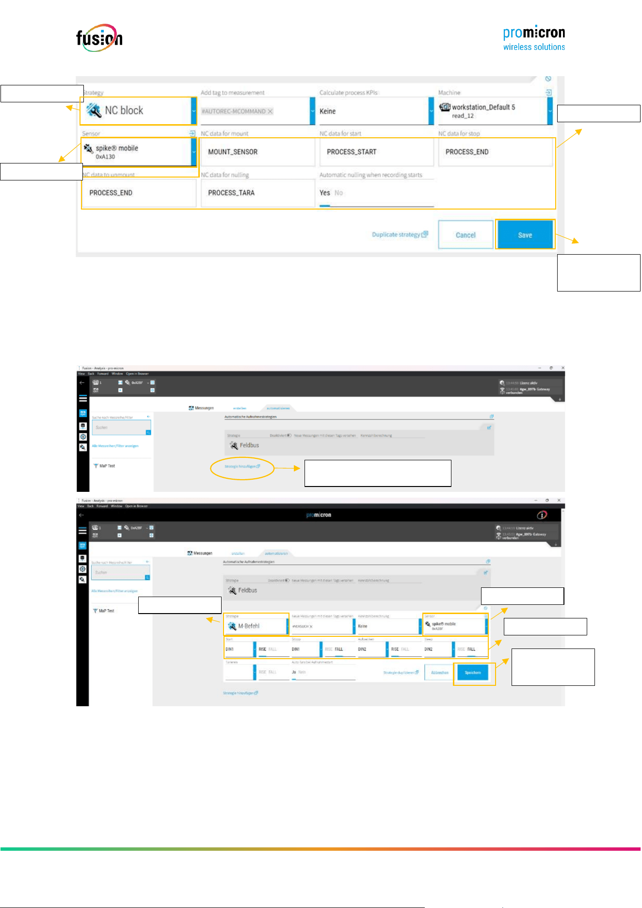
Setup example for Siemens:
Use the button to add a new strategy
Choose NC block
Set settings
Save to apply the
settings
Choose Sensor
Seite 33 von 67
© pro-micron GmbH - Alle Rechte vorbehalten.
4.4.3 M COMMAND TRIGGER
An M-command trigger is a command used in CNC programming to trigger specic actions on a machine.
The letter "M" stands for " Miscellaneous " and is followed by a number that indicates the specic
command.
4.4.4 FIELDBUS TRIGGER
A eldbus trigger is a function used in the control of a machine to trigger communication via a eldbus. A
eldbus is an industrial data bus that makes it possible to connect various devices and components and
exchange data. It is usually inserted into the control program and placed at specic locations where
communication via the eldbus is required.
Use the button to add a new strategy
Choose M-command
Choose Sensor
Set settings
Choose NC block
Set settings
Save to apply the
settings
Save to apply the
settings
Choose Sensor
Seite 34 von 67
© pro-micron GmbH - Alle Rechte vorbehalten.
4.5 SET TAGS AND LABELS
Tags and labels simplify traceability and marking of special events in the process. They are suitable as
lter parameters for later analyses. Tags are essentially used to add information about the process to the
data, such as “test,” “tool break,” or “groove.” Labels provide information about process parameters such
as feed speed and cutting depth, as well as downstream quality results (e.g. surface quality and
tolerances).
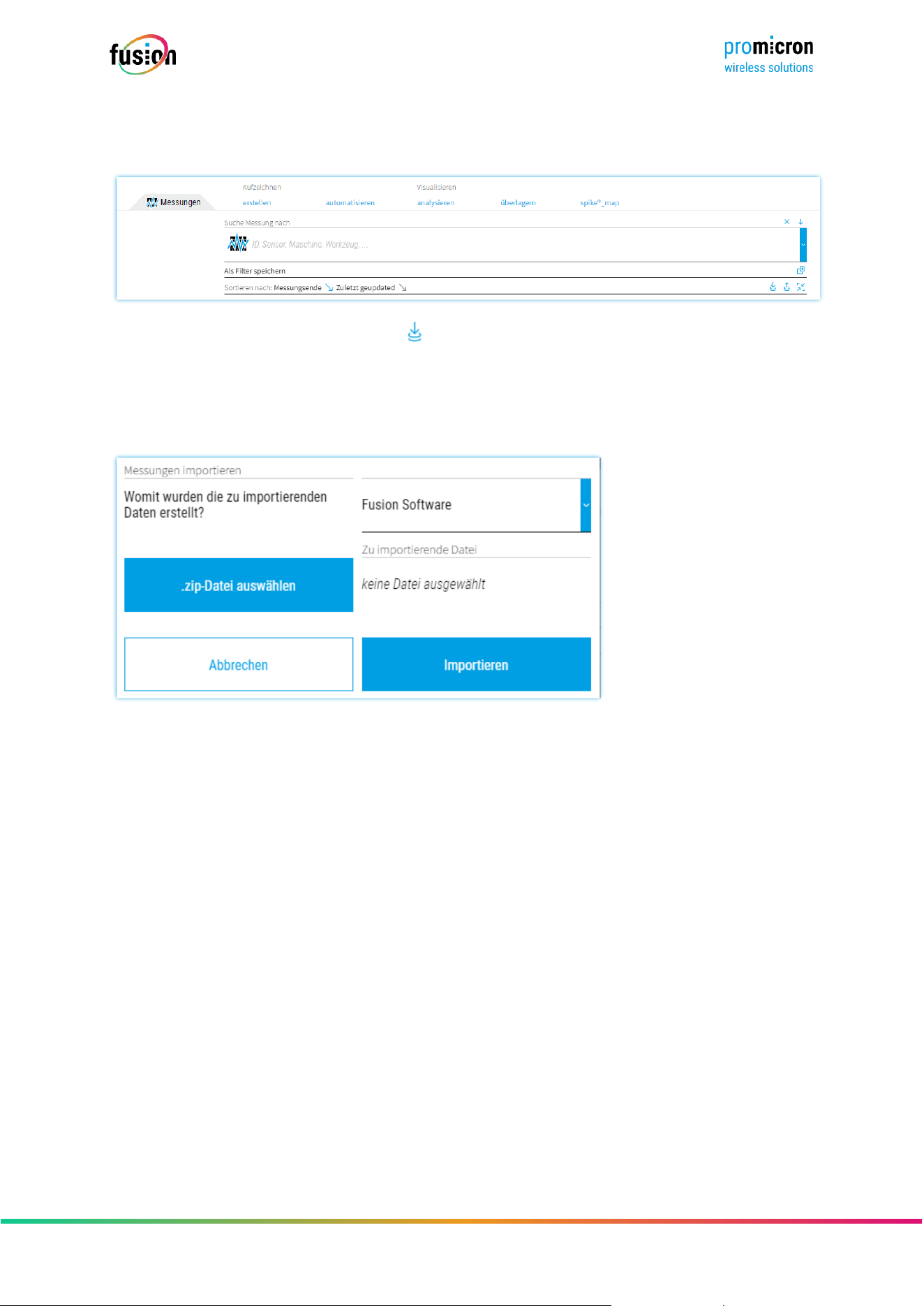
To create a new tag, select Tags > “create” in the bar at the top. Here the name, text color and description
of the selected tag can be edited and added to the database by “Save”.
To create a new label, select “Create” in the Labels tab at the top. Now the name, description and category
of the label to be created can be selected and the desired unit can be named or stored for the category.
Seite 35 von 67
© pro-micron GmbH - Alle Rechte vorbehalten.
4.6 IMPORT MEASUREMENT DATA
To import measurements, click on the “Measurements” tab:
be imported using the database import icon
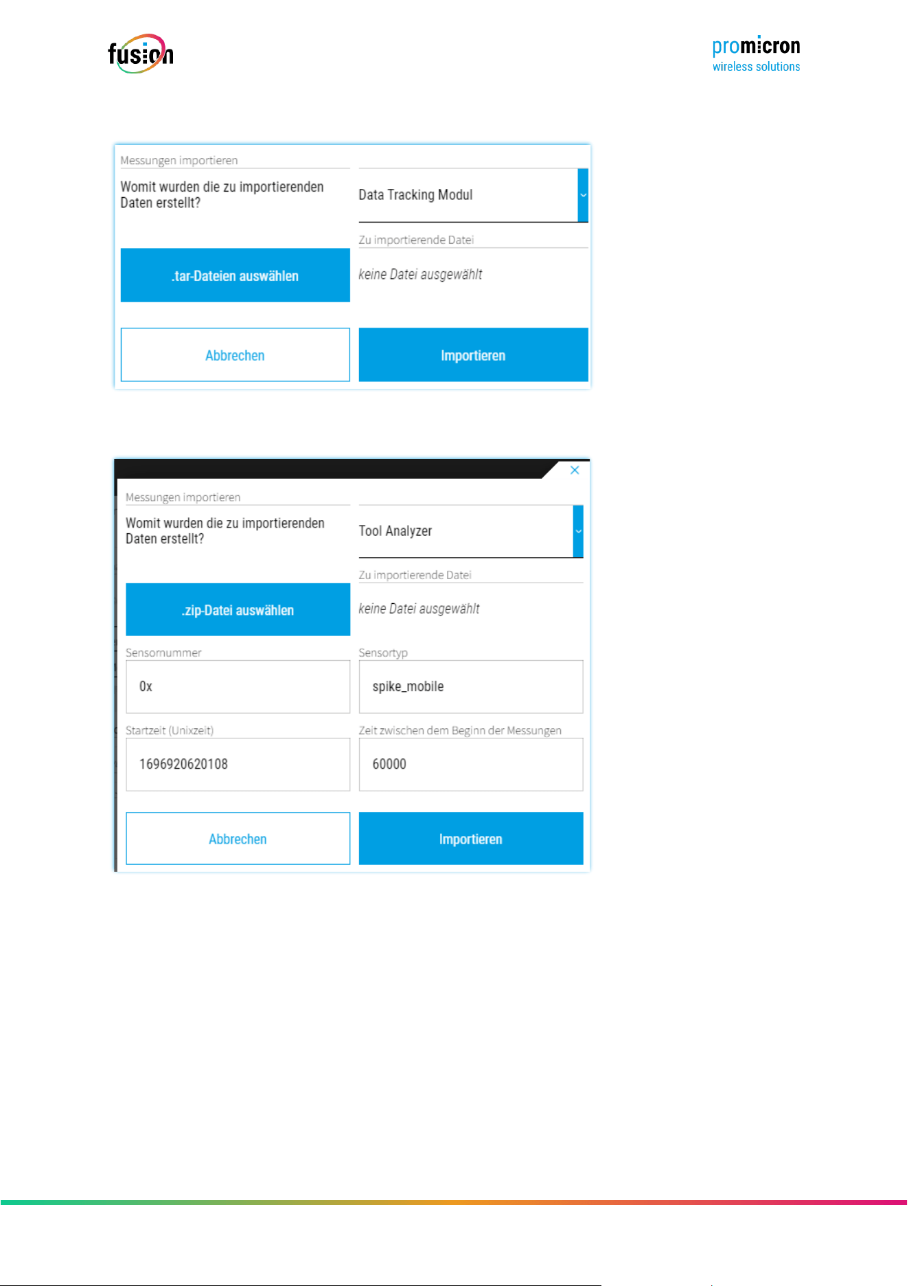
The following options are available for data transfer:
▪ Measurement data in . zip format recorded with the fusion V1.1 software:
Seite 36 von 67
© pro-micron GmbH - Alle Rechte vorbehalten.
▪ Measurement data in . tar format recorded with a data tracking module:
▪ Measurement data in . zip format, which were created with the Analyzer tool:
If the desired format is selected and the “Select le” button is clicked, the explorer opens and the desired
measurements can be selected in the database. Clicking “Import” starts the import process.
If data was recorded with an early version of fusion and is no longer compatible with the current version,
please contact promicron support to convert the data.
Seite 37 von 67
© pro-micron GmbH - Alle Rechte vorbehalten.
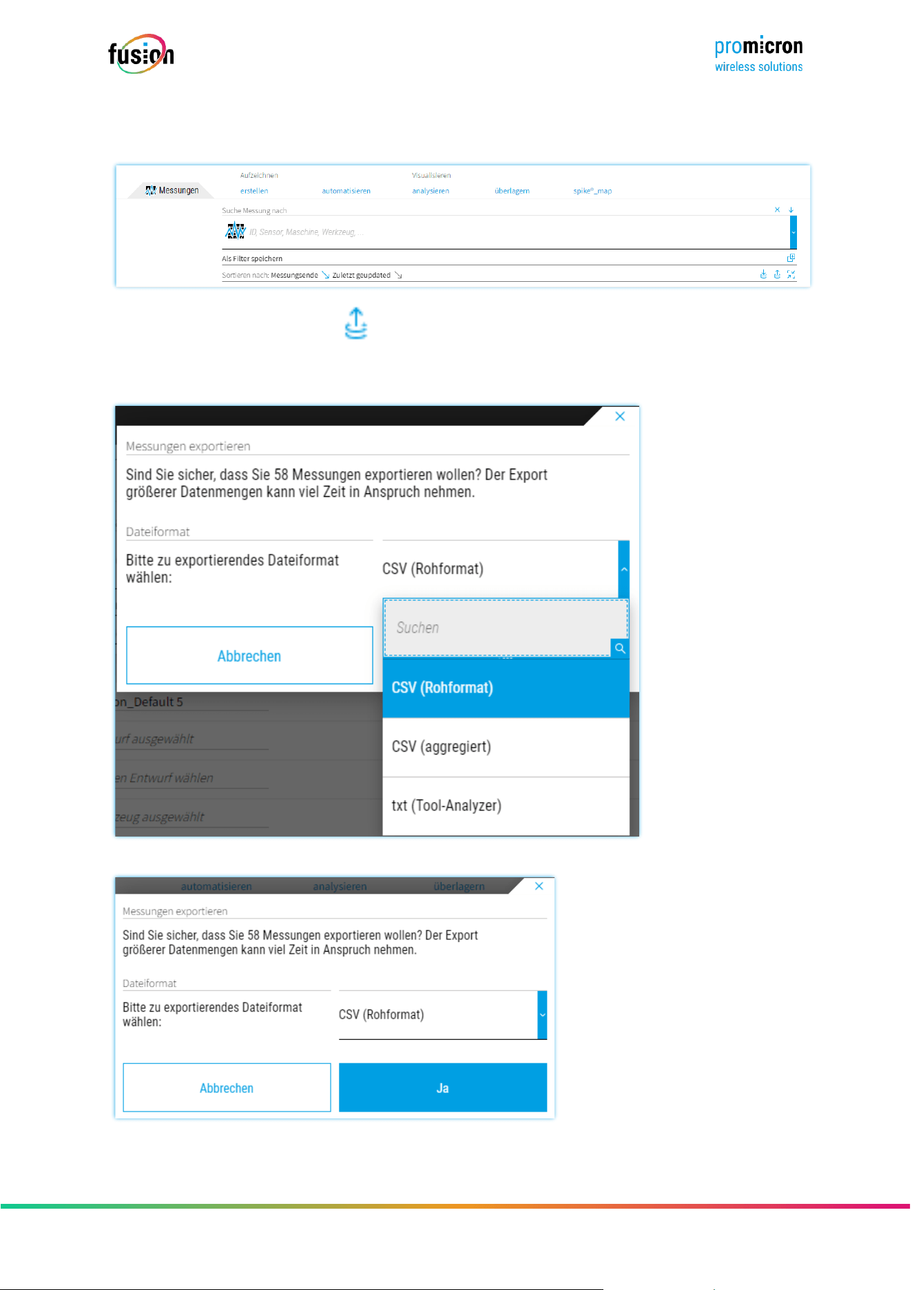
4.7 EXPORT MEASUREMENT DATA
To export measurement data, select the “Measurements” tab:
By clicking on the data export icon, a window opens in which you can select the le format with which
the data should be exported. The data can be saved as . csv (raw format or aggregated) as well as . txt
(for Tool Analyzer).
After selecting the le format, conrm the process with “Yes” and the export starts.
Seite 38 von 67
© pro-micron GmbH - Alle Rechte vorbehalten.
4.8 SPIKE®_MAP
To eciently manage large amounts of raw data, tools for automatic storage, sorting, labeling,
synchronization and validation are necessary.
fusion software, the data is prepared so that it can be eciently interpreted and correlated without any
further manual effort.
This process data is also suitable for creating a digital twin.
The machine data is transferred to the software via an interface and recorded there. A model of the
workpiece can be generated from the position information and the individual forces can be displayed for
each individual point. The NC code can be displayed for each of these points.
Further analysis functions include the “ fusion analysis” software, which is used to evaluate large amounts
of data without a measuring system.
Seite 39 von 67
© pro-micron GmbH - Alle Rechte vorbehalten.
5 PARAMETERS AND SELF-TEST SEE
5.1 SETTING SPECIFIC PARAMETERS WITH SPIKE® MOBILE
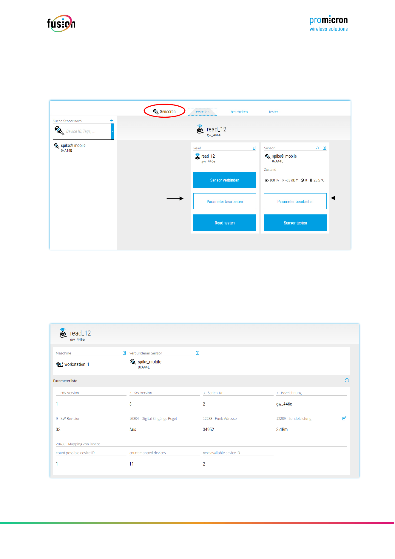
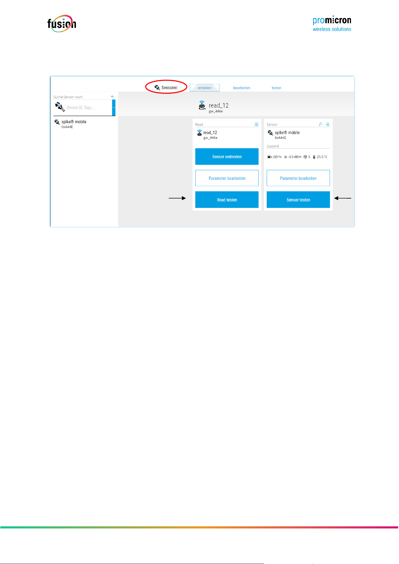
(1) To edit the recipient (Read), click Read > “Edit Parameters”.
(2) To edit the sensor, click Sensor > “Edit Parameters”.
Parameter list for the read:
(1)
(2)
Seite 40 von 67
© pro-micron GmbH - Alle Rechte vorbehalten.
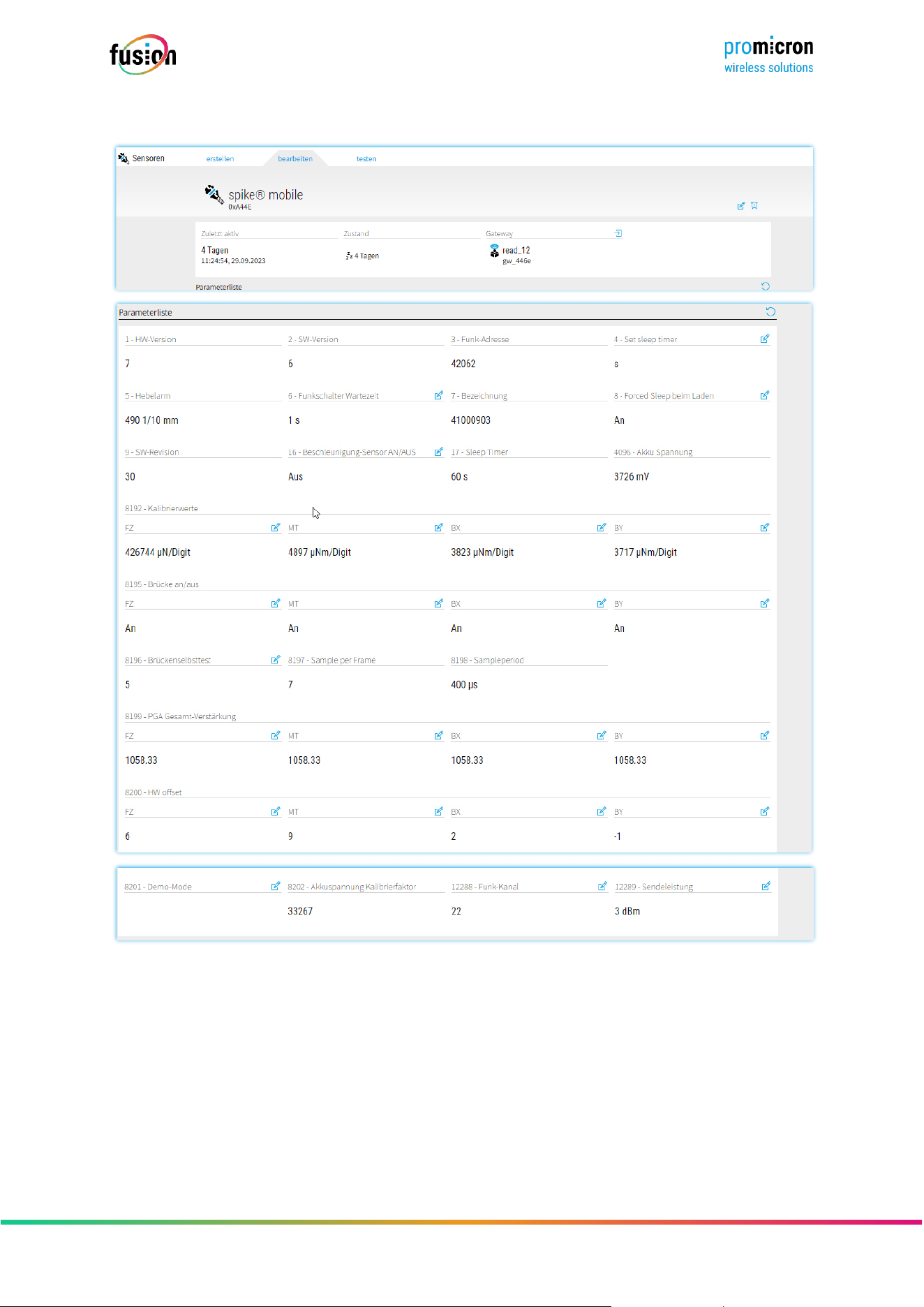
Parameter list for the spike®mobile :
Seite 41 von 67
© pro-micron GmbH - Alle Rechte vorbehalten.
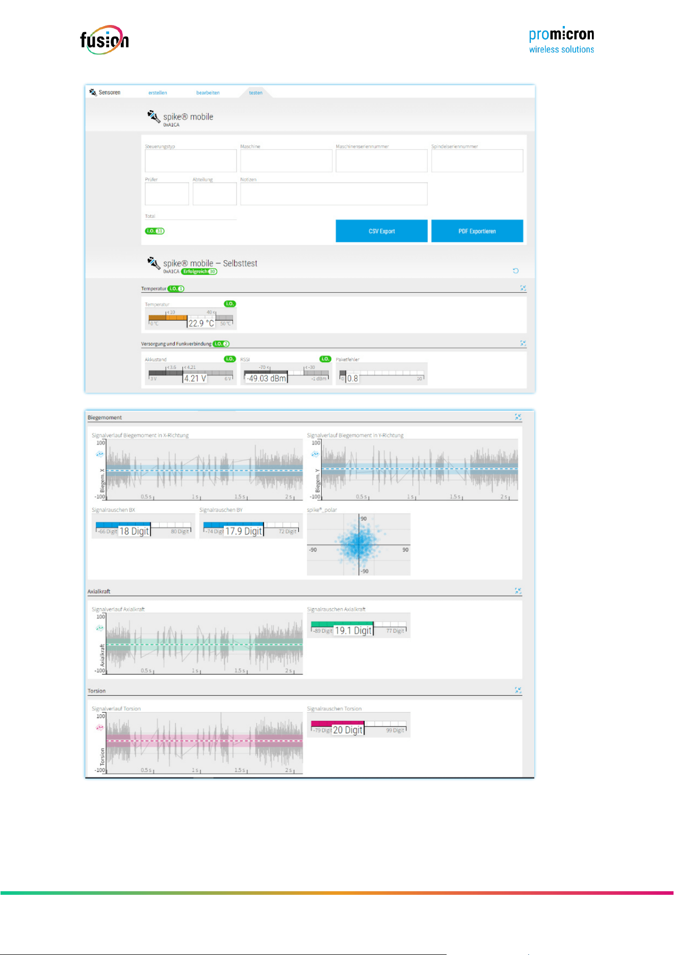
5.2 SELF-TEST WITH SPIKE® MOBILE
(1) To test the receiver, click on “Test Read” (self-test)
(2) To test the sensor, click on “Test Sensor” (self-test)
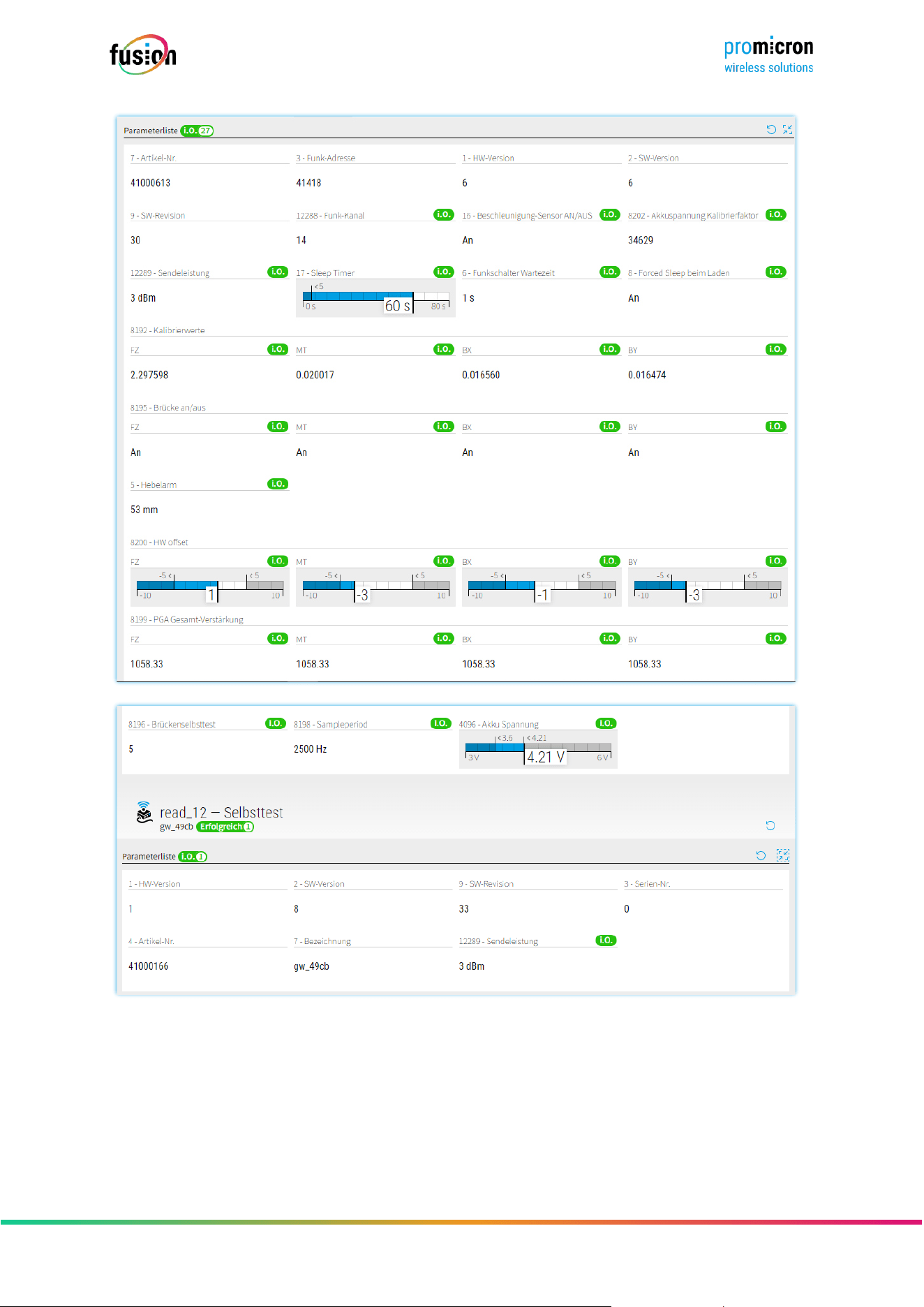
By clicking one of the two buttons, a self-test of the selected system is carried out and the result is
displayed. It is recommended to add optional information about the entire system before saving. The result
of the self-test can be saved in a le in . csv or . txt format (“ CSV Export ” or “PDF Export”) can be output
and saved.
(1)
(2)
Seite 42 von 67
© pro-micron GmbH - Alle Rechte vorbehalten.
Seite 43 von 67
© pro-micron GmbH - Alle Rechte vorbehalten.
Since a sensor self-test always requires a receiving device, both the sensor and the receiving unit are
checked during a sensor self-test.
Seite 44 von 67
© pro-micron GmbH - Alle Rechte vorbehalten.
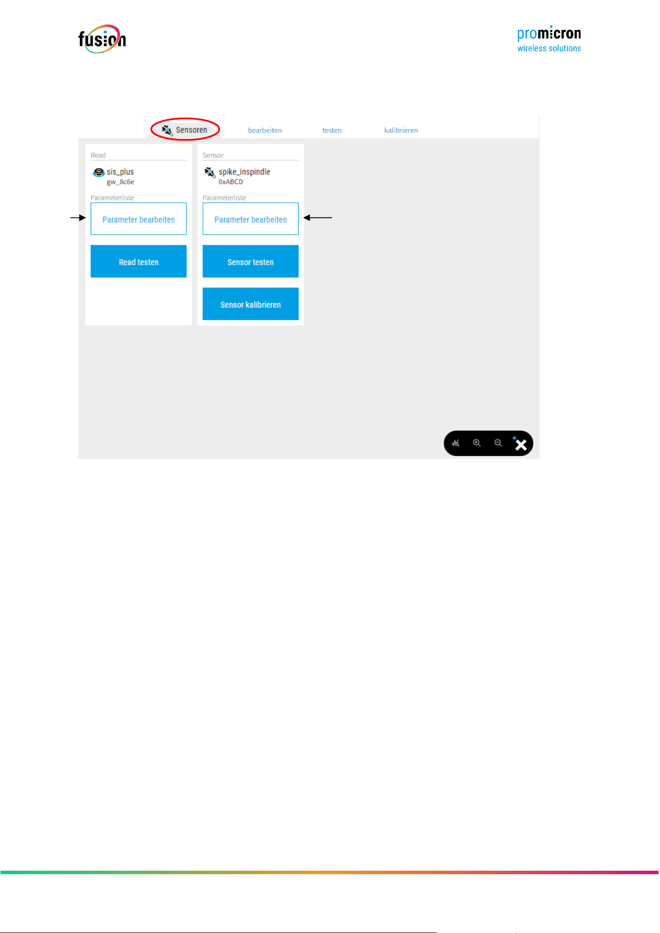
5.3 SETTING SPECIFIC PARAMETERS WITH INSPINDLE
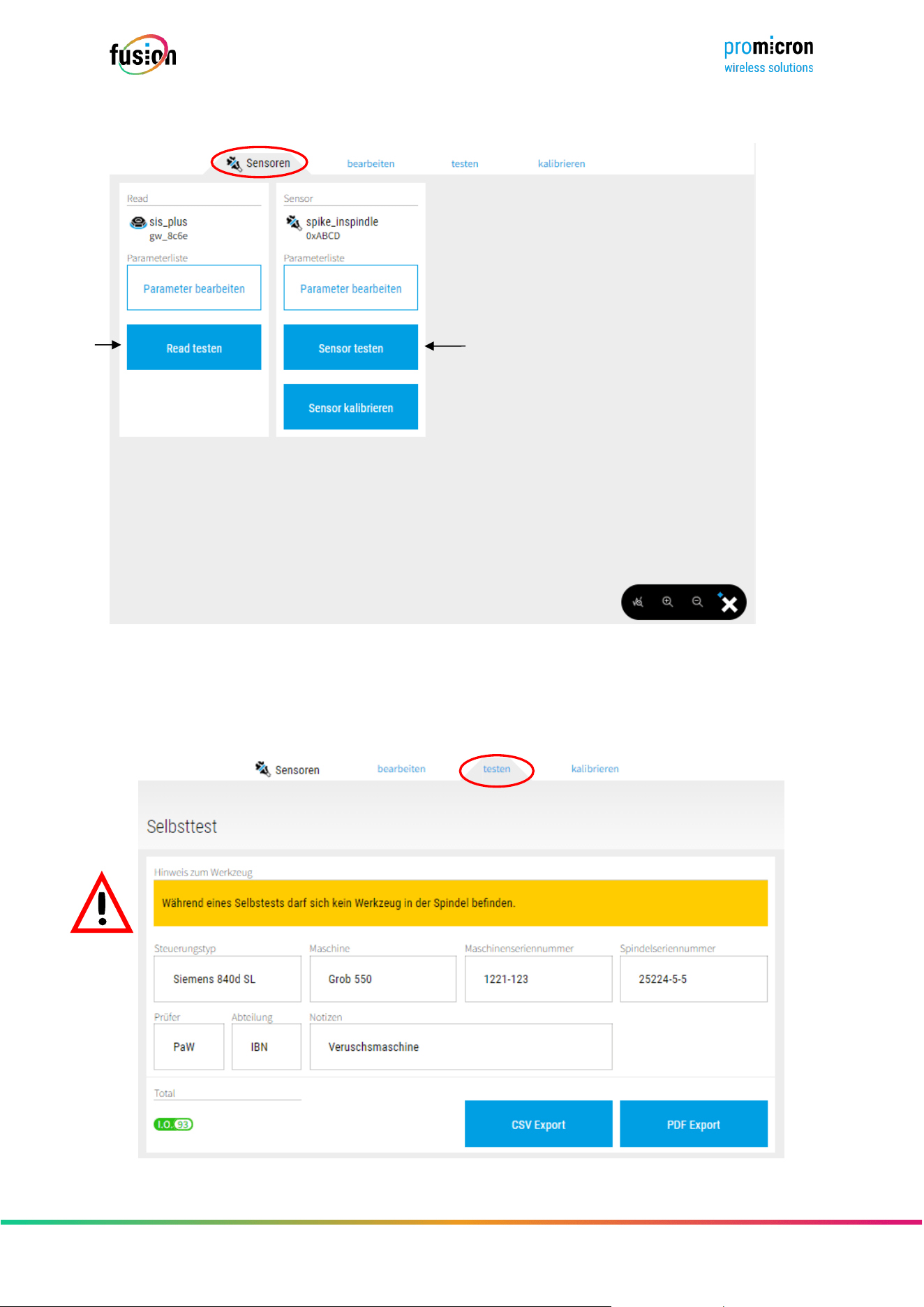
(1) To edit the recipient (Read), click on “Edit parameters”.
(2) To edit the sensor, click on “Edit parameters”.
(2)
(1)
Seite 45 von 67
© pro-micron GmbH - Alle Rechte vorbehalten.
5.4 SELF-TEST WITH INSPINDLE
It is recommended that verication and calibration of an InSpindle system be performed sequentially .
▪ Self-test : for basic checking of the system and its parameters
▪ Chip in spindle: for teaching in a dened error chip using error tools
▪ Pull-in force: for calibrating the pull-in force using an external tool
▪ Process force and overload: for calibrating the process force
▪ Temperature compensation: for calculating system-specic coecients for temperature compensation
Seite 46 von 67
© pro-micron GmbH - Alle Rechte vorbehalten.
5.4.1 CARRY OUT SELF-TEST
(1) To test the read, click “Test Read”.
(2) To test the sensor, click “Test Sensor”.
(2)
(1)
Seite 47 von 67
© pro-micron GmbH - Alle Rechte vorbehalten.
To carry out the self-test correctly and to avoid damage, there must be no tools in the spindle. It is again
recommended to add optional information about the entire system before saving.
The self-test can be done either in . csv format or in . saved in PDF format .
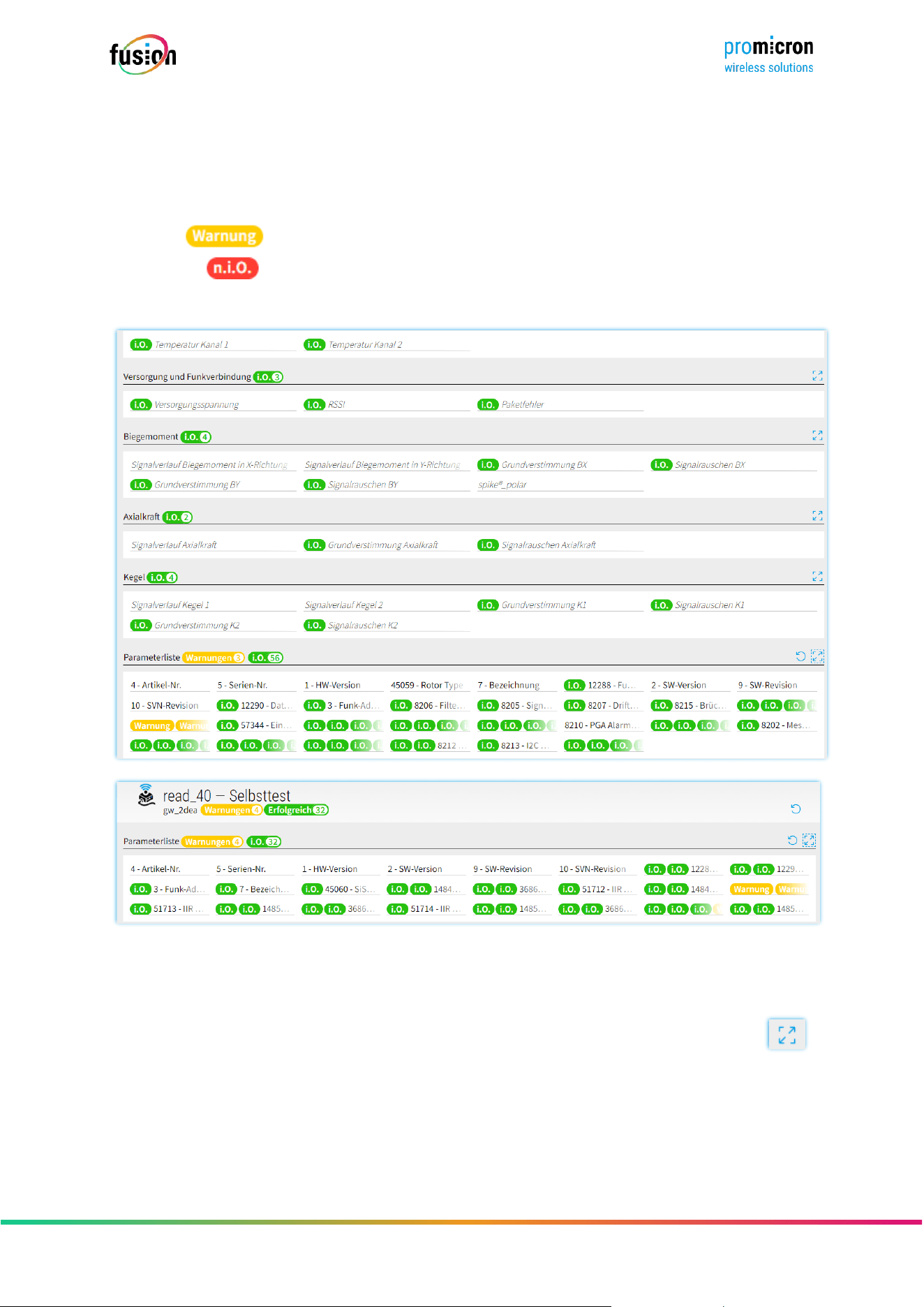
“Total” shows how many values are OK (IO up to 93); when scrolling, the self-test is listed.
A warning is given if a value deviates from the default value. If a value or parameter is rated
as “ not OK , ” a calibration must be carried out.
By expanding the individual columns, the individual test steps can be viewed in more detail.
Seite 48 von 67
© pro-micron GmbH - Alle Rechte vorbehalten.
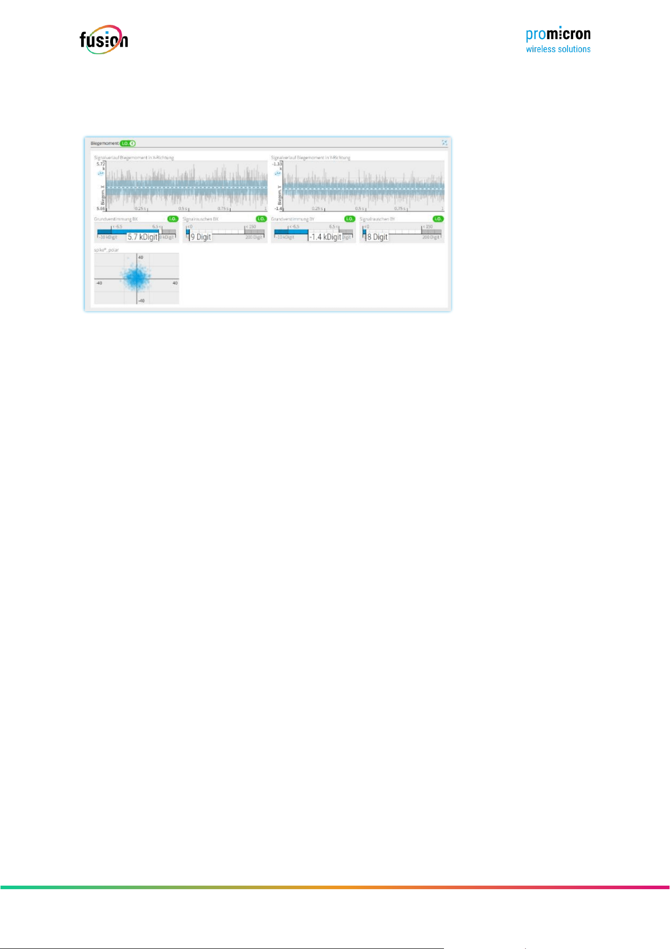
The detailed consideration of the bending moment provides, for example, information on the signal curve
of the bending moment, the basic detuning and the signal noise, each differentiated according to the x
and y axes. The recommended value range is visible.
Seite 49 von 67
© pro-micron GmbH - Alle Rechte vorbehalten.
5.4.2 CALIBRATING THE INSPINDLE
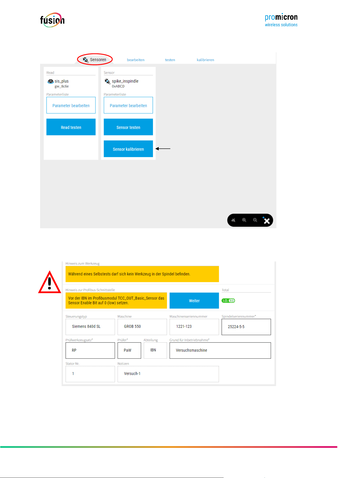
(1) To calibrate the sensor, click on “Calibrate Sensor” or select Sensors > “Calibrate” from the menu
The “calibrate” tab is password protected and only accessible to authorized personnel.
As part of the calibration, a self-test is carried out again. The message therefore appears repeatedly that
no tool may be clamped in the spindle. In addition, a parameter for the calibration period must be changed
via the Probus interface.
(1)
Seite 50 von 67
© pro-micron GmbH - Alle Rechte vorbehalten.
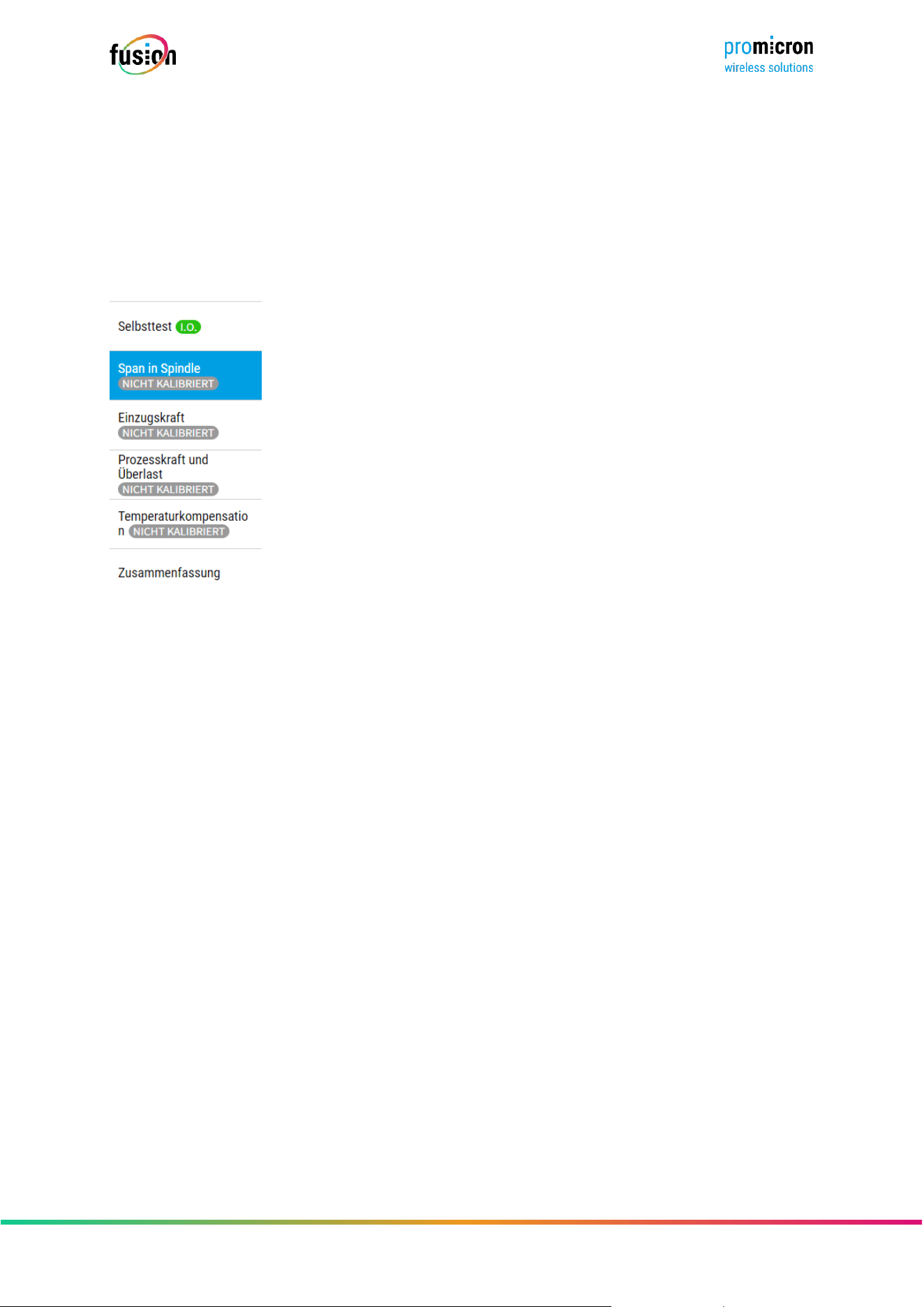
“Total” shows how many variables and parameters were classied as correct or suitable during the self-
test.
For sustainable documentation, we recommend manually inserting additional information (example
illustration). The elds marked with a * are mandatory and must be lled out.
The result of the self-test is listed below the input mask.
After completing the self-test, you can click on “Next”. The green “IO” symbol will then appear in the menu
on the left.
Seite 51 von 67
© pro-micron GmbH - Alle Rechte vorbehalten.
5.4.3 CHIP IN LOCKERS L
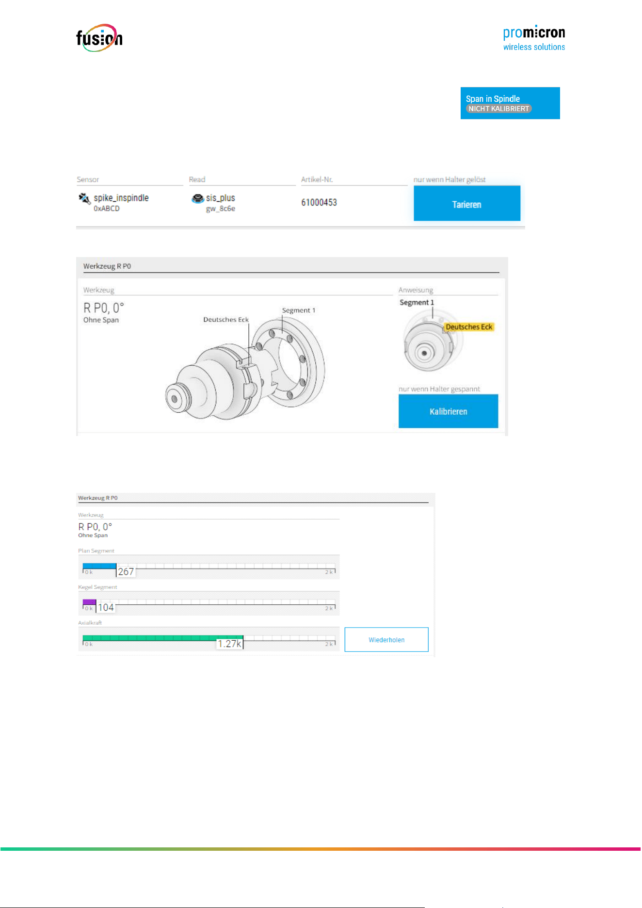
After calibrating the spike_InSpindle, the Span in Spindle function is calibrated.
The button must be selected for this.
To calibrate the chip in spindle functionality, the error chip calibration tool set with the reference tool RP0
and the error chip calibration tools P S0 10 , P S1 10 , R S0 30 and R S2 30 is required.
The holder must be loosened and secured from falling. Then click on “Tare”.
After the holder has been loosened, the RP0 tool is used. The RP0 tool is inserted manually into the motor
spindle as shown. Please note that the "German corner" (notch in the tool) is to the right of segment 1,
corresponding to position 0° . The tool is clamped by the machine, then click on "Calibrate".
The following values should be displayed at all positions with the RP0 tool:
Plan segments: < 0.4k
Cone segments: < 0.2k
Axial force: > 0.9k
If one of these values or several values are outside the recommended range, the tool must be removed
and cleaned manually. The calibration must then be repeated.
Seite 52 von 67
© pro-micron GmbH - Alle Rechte vorbehalten.
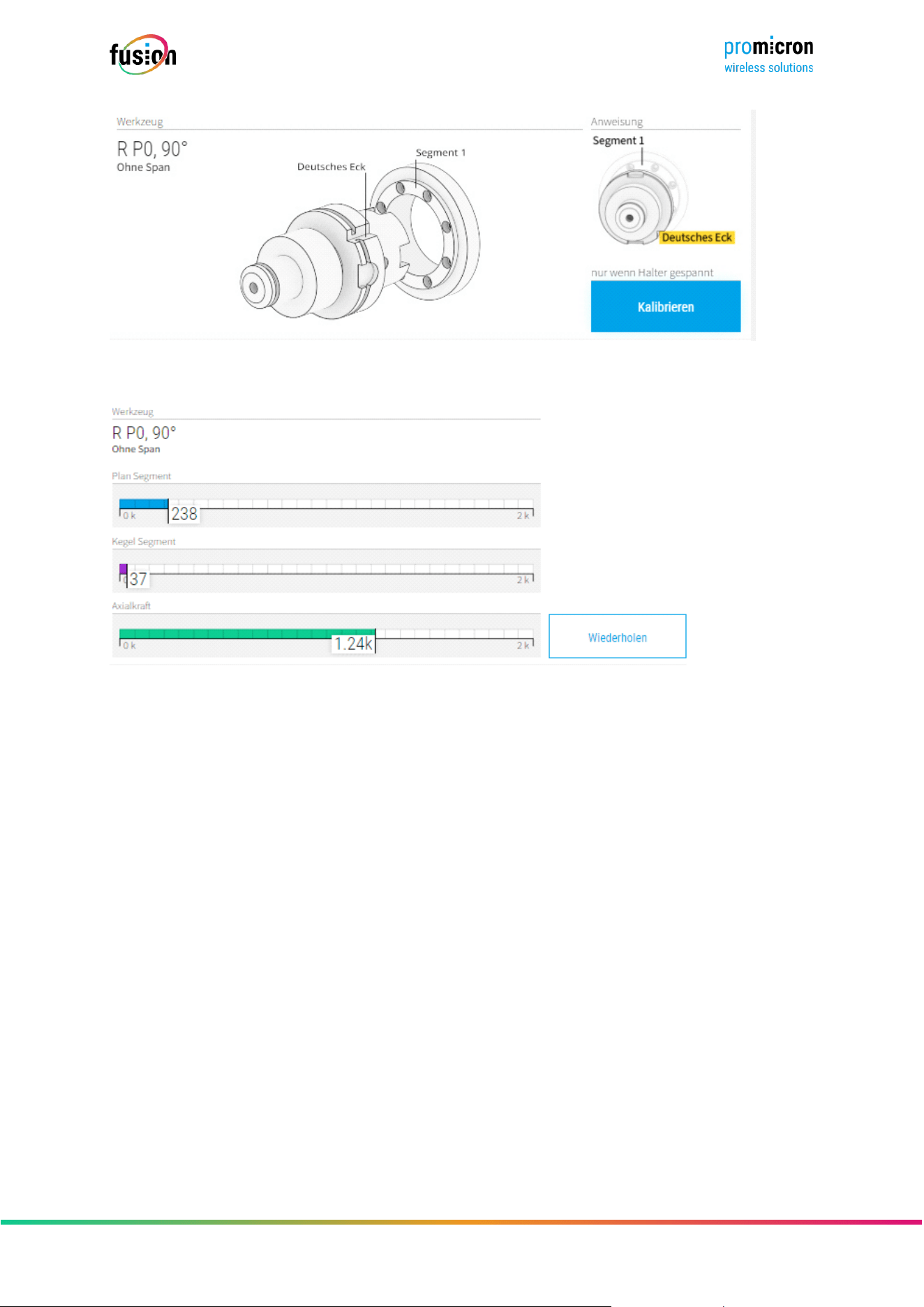
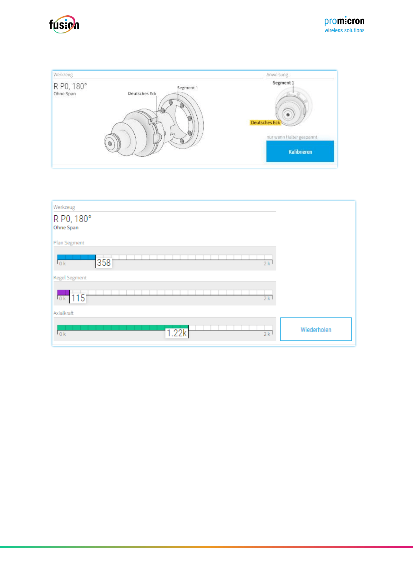
After calibrating to position 0°, the tool is rotated clockwise to position 90° as instructed . Once the tool
has been rotated 90° as shown on the right, it can be inserted and clamped again. Then click on “Calibrate”.
Seite 53 von 67
© pro-micron GmbH - Alle Rechte vorbehalten.
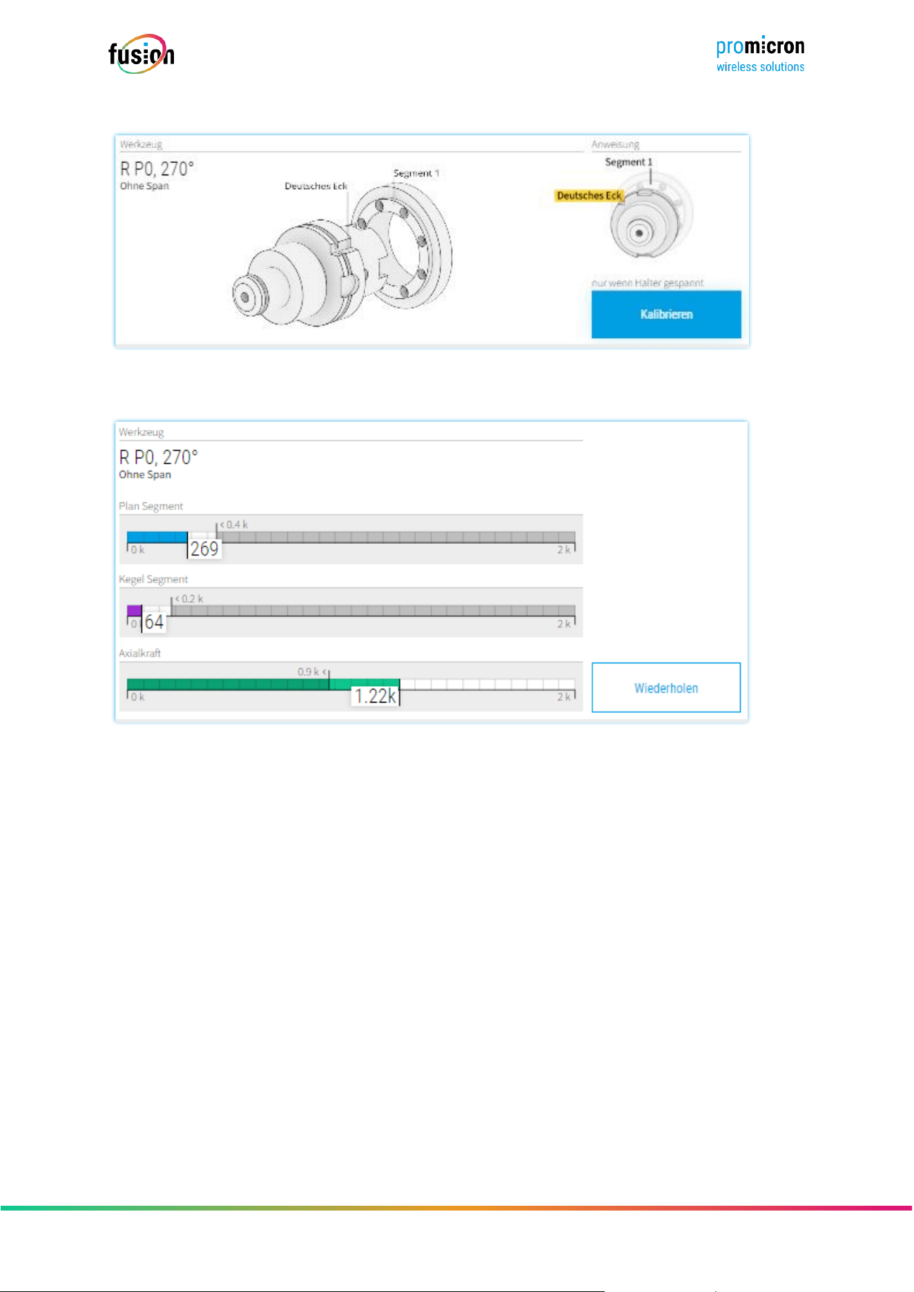
When calibration is completed at position 90°, the tool can be rotated another 90° to position 180° .
The “Deutsches Eck” is now opposite Segment 1, as shown in the instructions on the right. After the tool
is plugged in and clamped, click “Calibrate”.
Seite 54 von 67
© pro-micron GmbH - Alle Rechte vorbehalten.
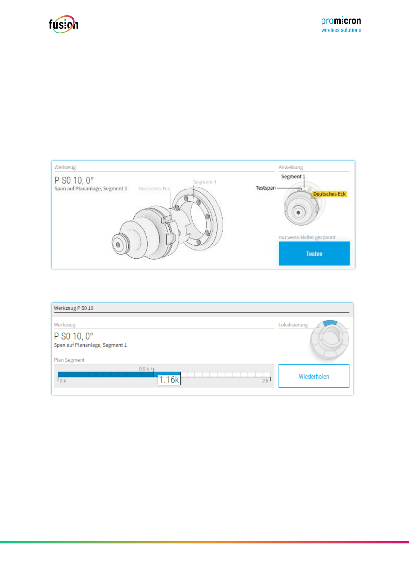
The last step is to rotate the tool again 90° clockwise to position 270° .
The “German Corner” is now to the left of Segment 1, see instructions on the right. After the tool is
clamped, “Calibrate” is selected.
The measurements with the RP0 tool form the reference value for the following steps.
Seite 55 von 67
© pro-micron GmbH - Alle Rechte vorbehalten.
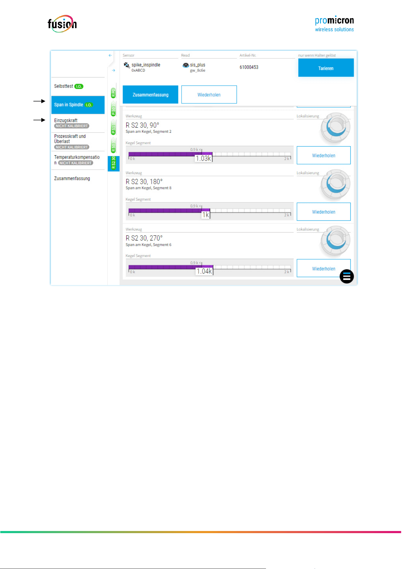
The error chip tools are then used to check whether the spike_InSpindle reliably detects the error chip.
With the tools P S0 10 and P S1 10, a dened 10 µ error chip is specied on the planar system. The position
of the error chip in the two tools differs by 45° in relation to the four driving grooves.
With the tools R S0 30 and R S1 30, a dened 30 µ error chip is specied on the conical surface. The
position of the error chip in the two tools differs by 45° in relation to the four driving grooves.
P S0 10
The process is analogous to calibrating with the RP0 tool. The tool must be inserted according to the
instructions and then clamped, whereby the positioning of segment 1 and the test chip (alternatively
“German corner”) must be strictly observed. Then click on “Test”.
The software shows at which position a chip was detected. If the position and size of the measured
value match, the test is successful.
A chip on the plan system must have a value greater than 0.9k for the test chip to be recognized. If the
value is less than 0.9k, the tool must be removed and the test repeated.
This process must be carried out equally for the positions 90°, 180° and 270°.
P S1 10, R S0 30, R S2 30
The steps of P S0 10 are repeated identically with the tools P S1 10 , R S0 30 and R S2 30 .
Seite 56 von 67
© pro-micron GmbH - Alle Rechte vorbehalten.
(1) After calibration with the RP0 tool and the test with the four error chipping tools, a green “IO”
symbol appears in the “Chip in Spindle” tab.
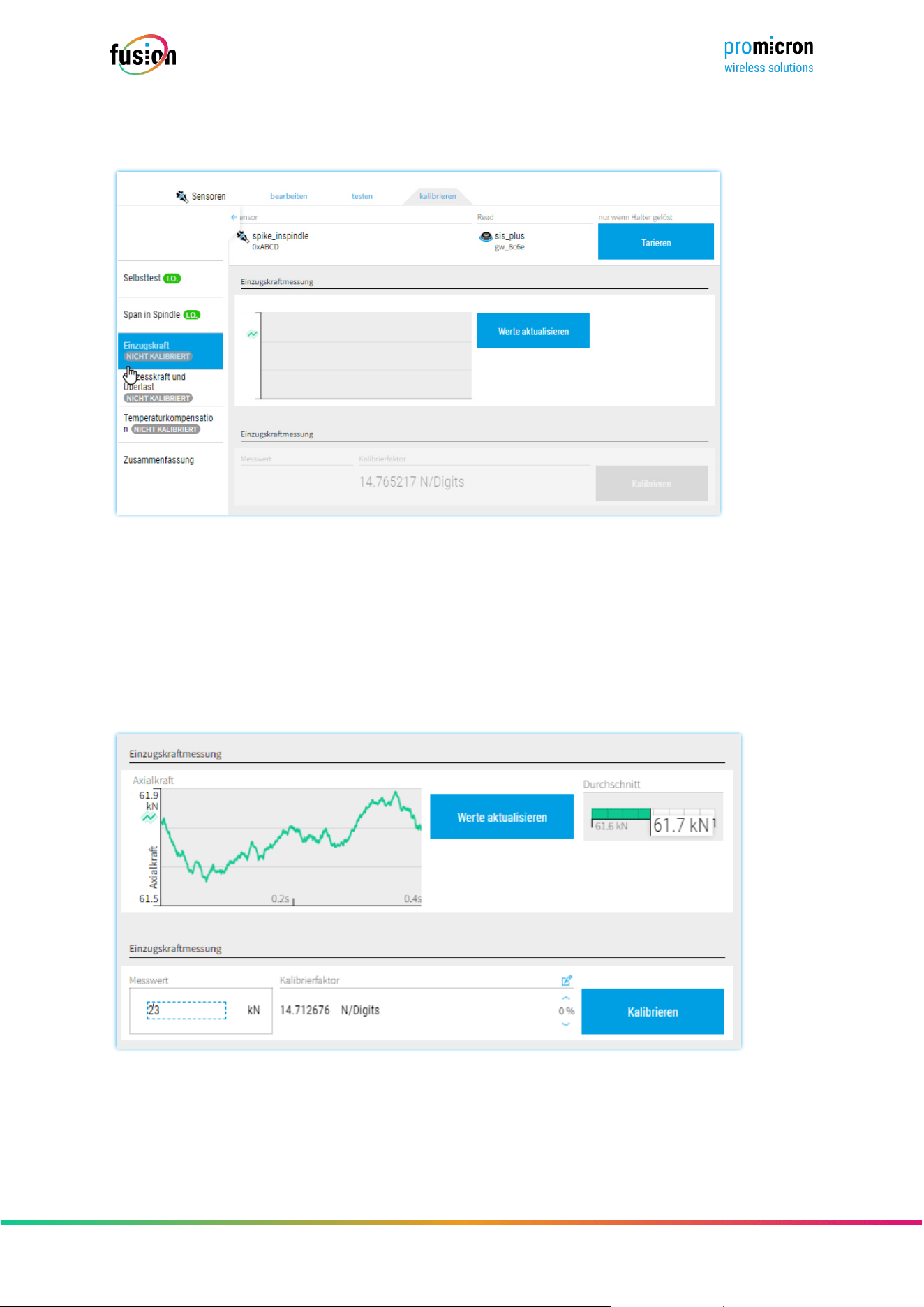
(2) The pull-in force measurement is then calibrated. To do this, click on “Pull-in force”.
(1)
(2)
Seite 57 von 67
© pro-micron GmbH - Alle Rechte vorbehalten.
5.4.4 PULL-IN FORCE
An external measuring device is required to measure and calibrate the pull-in force.
➔ Before starting the pull-in force measurement, click on “Tare” to zero the measurement.
➔ Press “on” on the external pull-in force measuring device, then “Clear off” to zero it too.
➔ The measuring device is then replaced and clamped. The external measuring device determines
the pull-in force and displays the measured value in [kN]. This displayed value [kN] must be entered
in the software input mask. Then click on “Calibrate”.
(The values and graphs in the example are for illustrative purposes only).
➔ “Update values” can be selected to continuously display the measured values from the Spike
_inspindle.
Seite 58 von 67
© pro-micron GmbH - Alle Rechte vorbehalten.
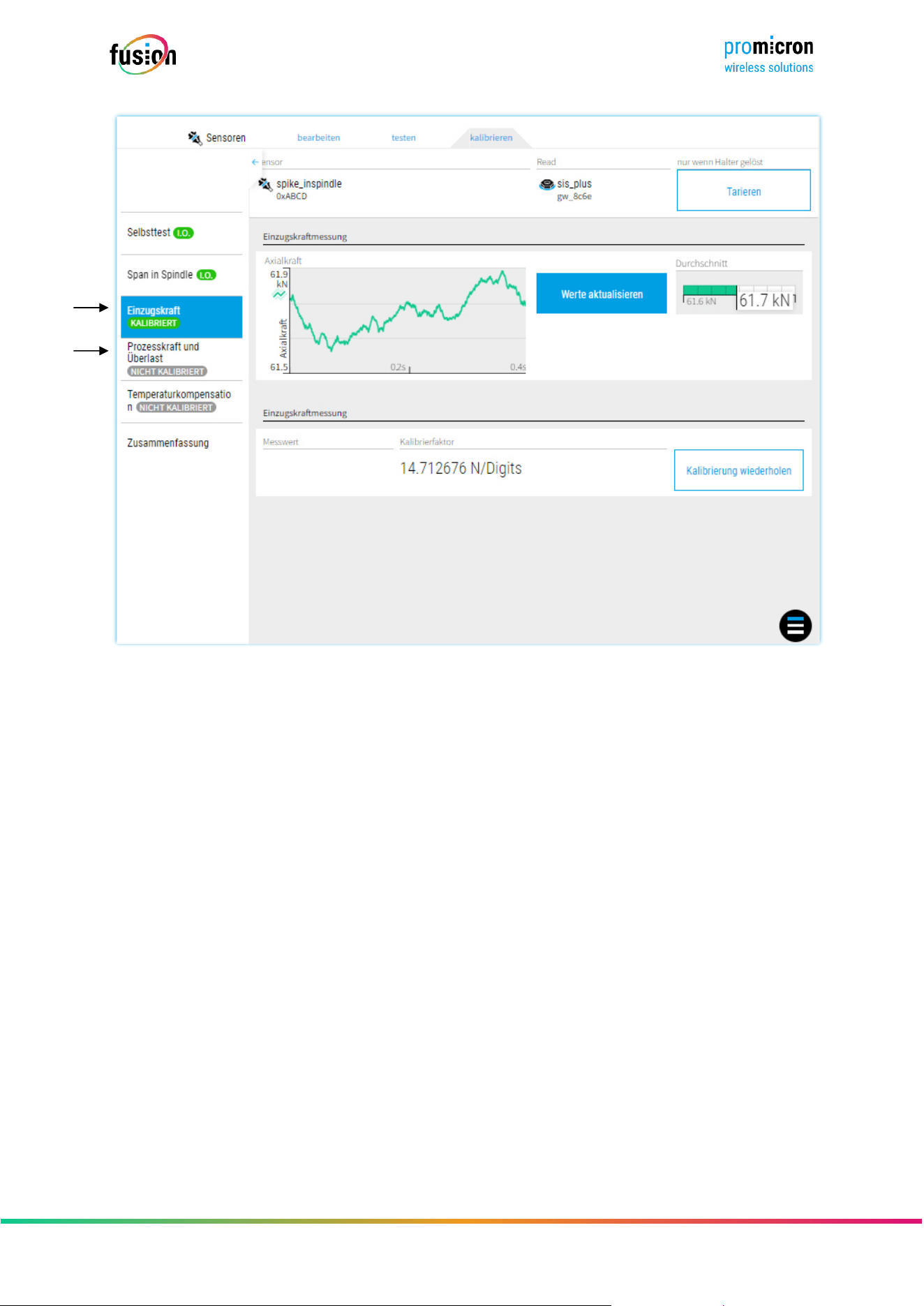
(1) After calibration with the external measuring device, a green “CALIBRATED” symbol appears in
the “Pull-in force” tab.
(2) “Process force and overload” is then set.
(1)
(2)
Seite 59 von 67
© pro-micron GmbH - Alle Rechte vorbehalten.
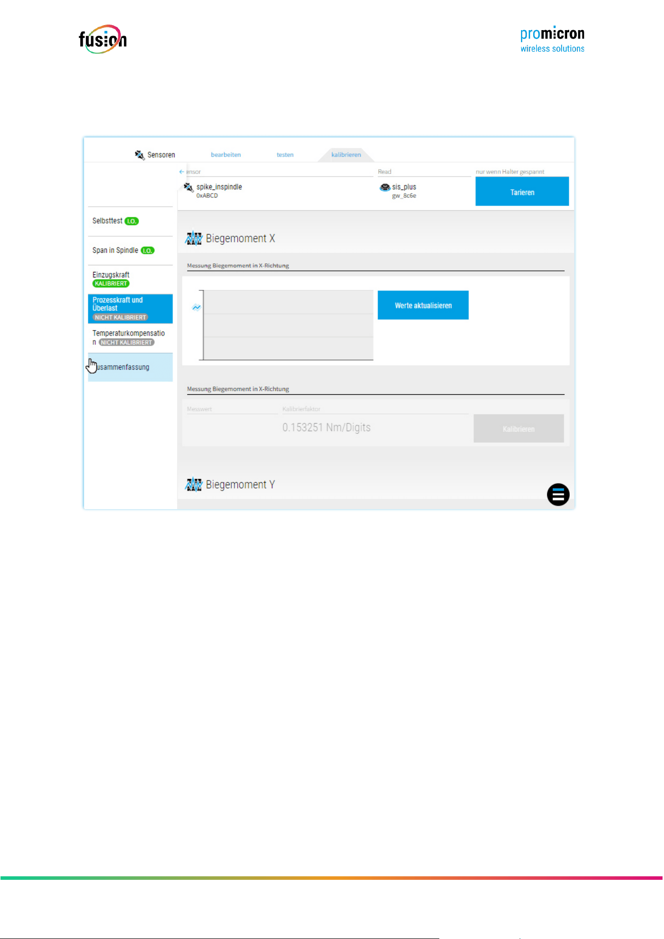
5.4.5 PROCESS FORCE AND OVERLOAD
To calibrate the process force, a specic ball tool clamped in a tool holder and a load cell are required.
The setting dimension of the ball tool must be known.
➔ First, the holder is clamped with the calibration tool (ball).
➔ Then click on “Tare”.
Seite 60 von 67
© pro-micron GmbH - Alle Rechte vorbehalten.
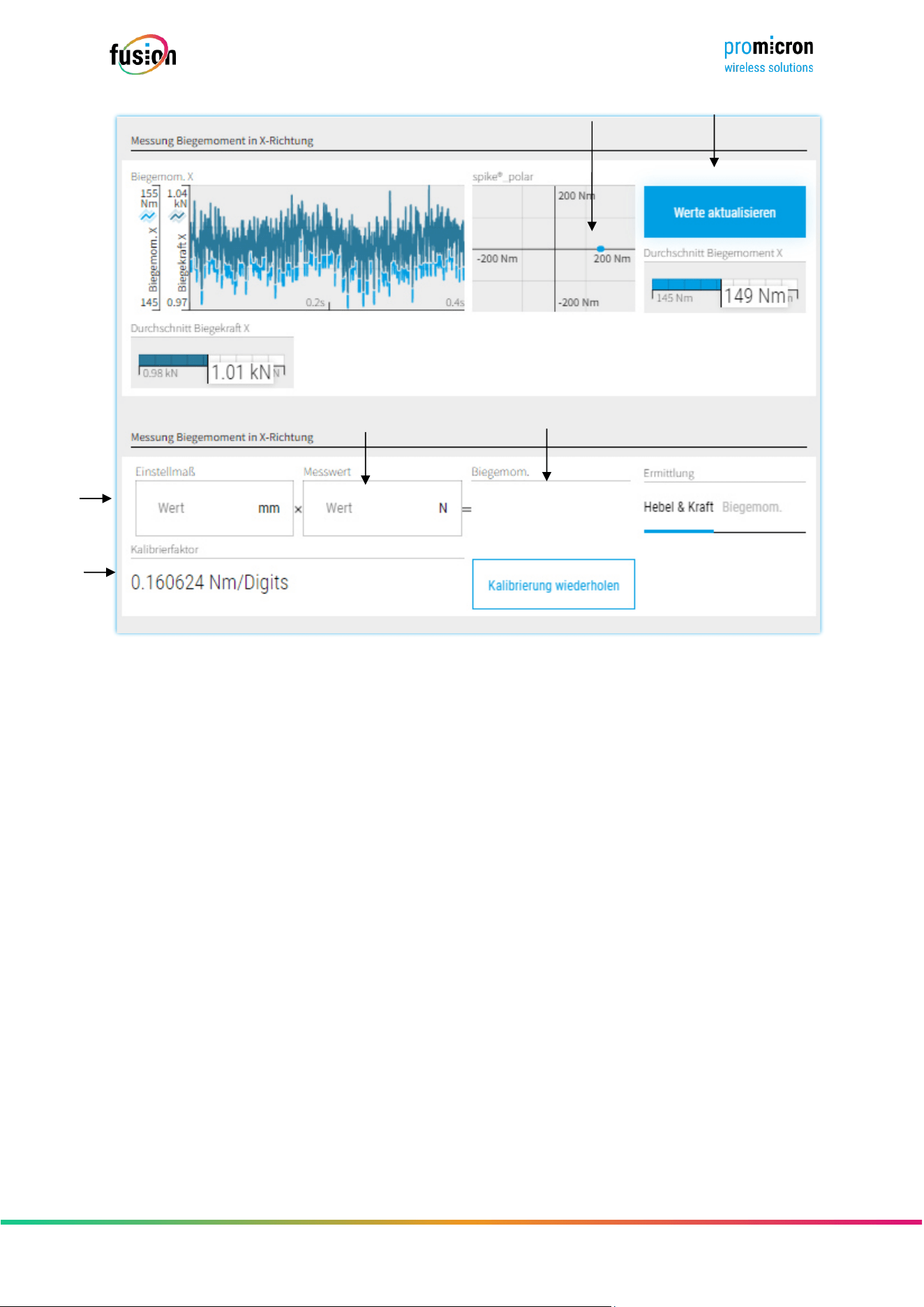
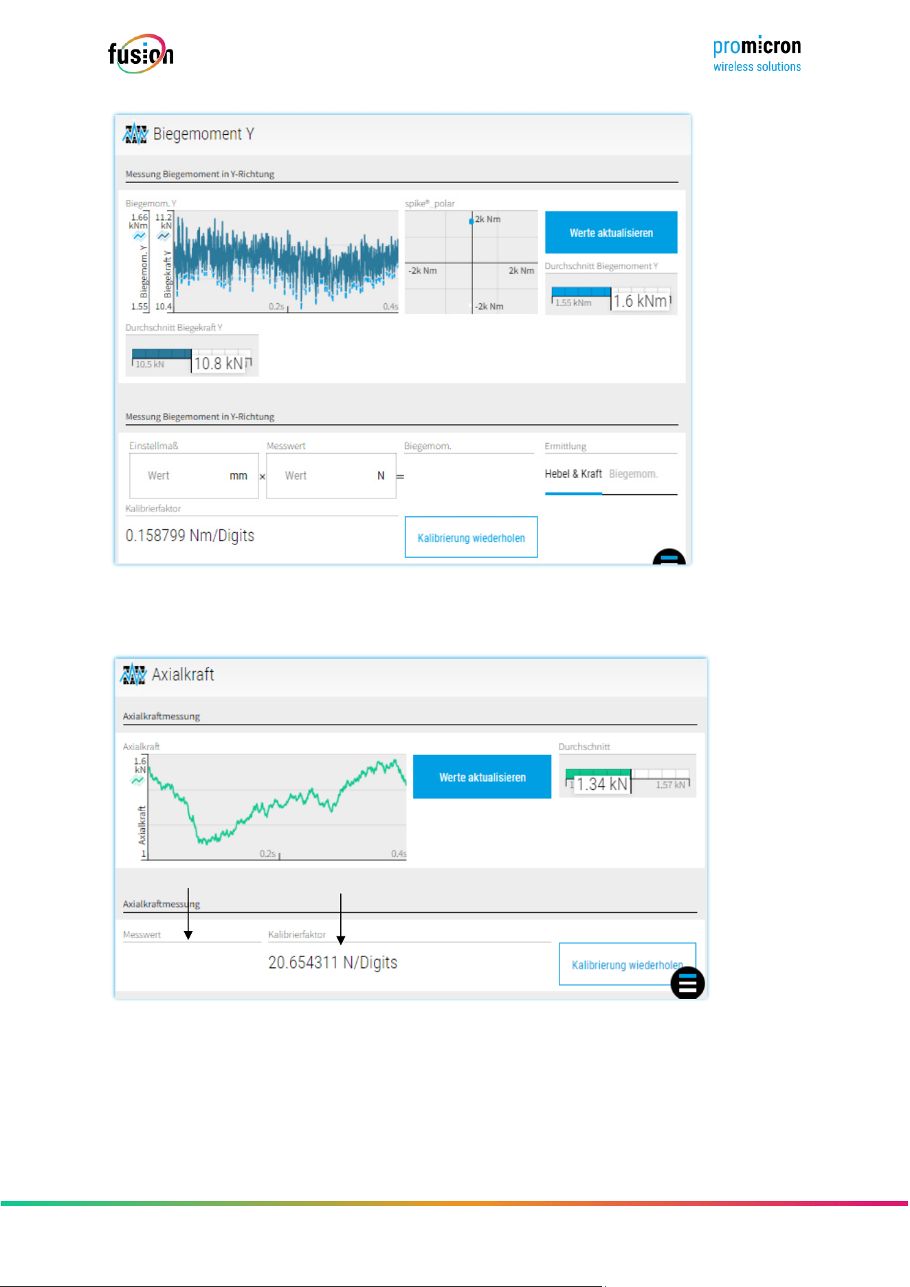
First, the bending moment is calibrated in the x direction.
(1) The motor spindle with the ball tool and the load cell must be positioned in such a way that
when the ball tool comes into contact with the load cell, the force is applied exclusively in the x
direction of the sensor. The force input in the y-direction should be minimal. The Spike_polar
shows the actual force distribution . Ideally, these measured values lie exclusively on the x-axis.
(2) The load cell shows the amount of force with which the ball acts on the load cell (thumb value
approximately 1000N). This measured value must be entered under “Measured value”.
(3) The setting dimension of the ball tool must be entered in the “Setting dimension” eld.
(4) The bending moment is calculated from the setting dimension and the measured value (via the
product of the lever arm and force).
(5) The correct calibration factor is displayed.
(6) By “Update values” the calibration factor is adopted and the display of the measurement data in
the history graph and in spike_polar is updated.
The procedure for calibrating the bending moment in the y-direction must be carried out in the same way.
To do this, the motor spindle must be rotated by 90° (clockwise or counterclockwise).
(1)
(3)
(2)
(5)
(6)
(4)
Seite 61 von 67
© pro-micron GmbH - Alle Rechte vorbehalten.
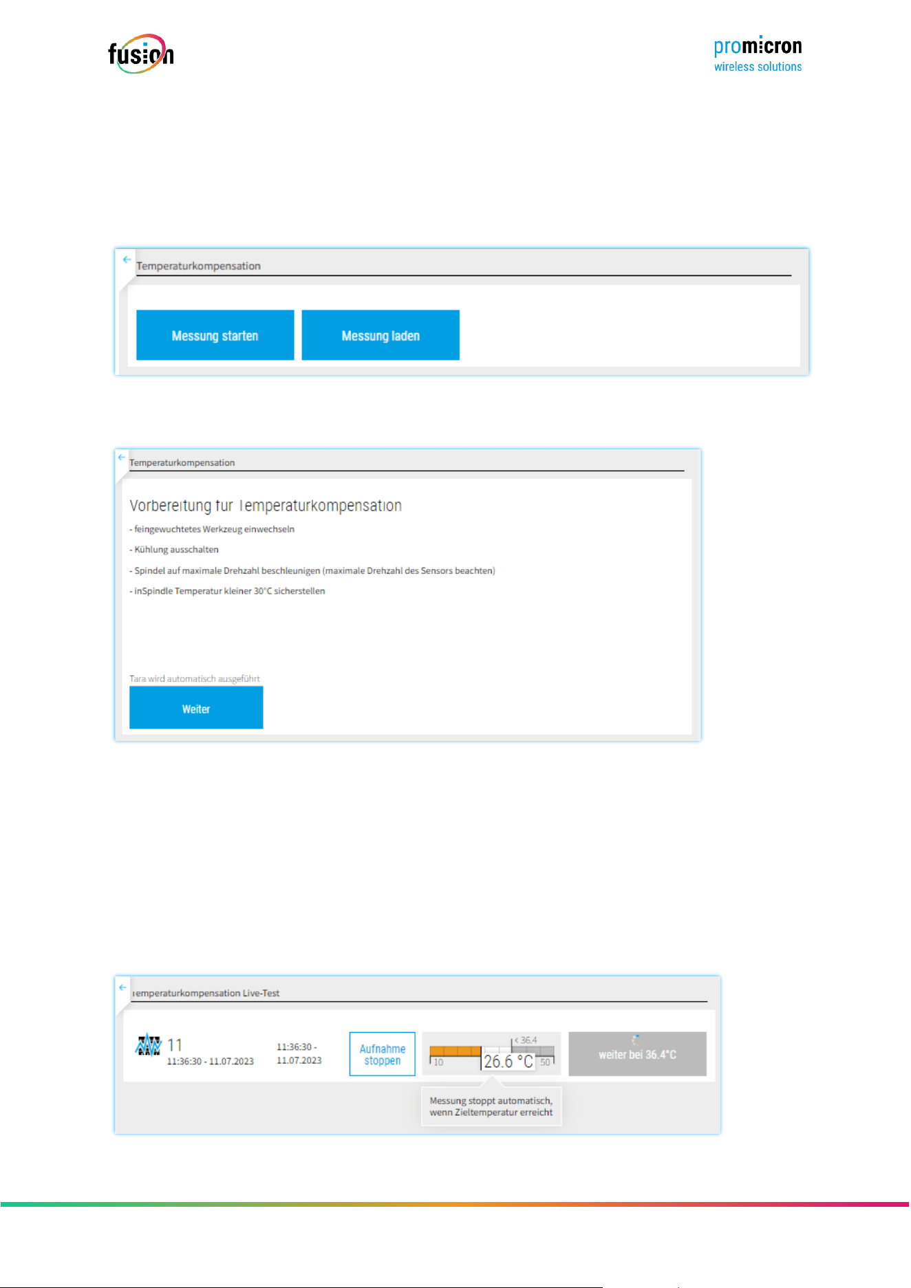
To determine whether an overload is acting on the motor spindle bearing, the axial force must be
calibrated. To do this, the load cell is aligned so that the calibration tool presses frontally onto the load
cell.
(1) The load cell indicates the amount of force with which the ball acts on the load cell (set to
approximately 1000N). This value must be entered under “Measured value”.
(2) The correct calibration factor is displayed.
(3) With “Update values” the calibration factor is adopted and the display of the measurement data
in the history graph is updated.
After calibrating the process force and the axial force, a green “CALIBRATED” symbol appears in the
“Process force and overload” tab. This is followed by “temperature compensation”.
(1)
(2)
Seite 62 von 67
© pro-micron GmbH - Alle Rechte vorbehalten.
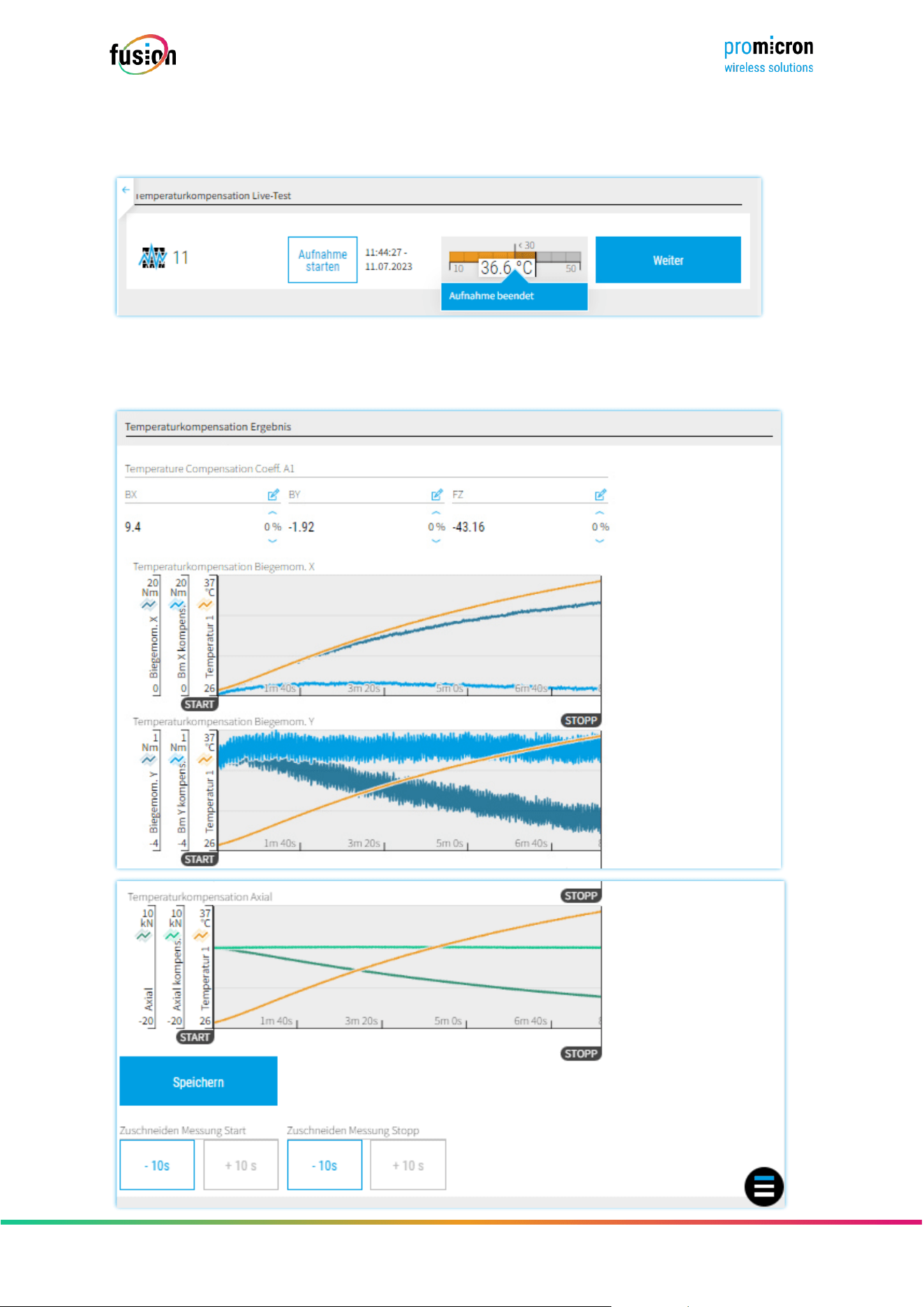
5.4.6 TEMPERATURE COMPENSATION
To correct the thermal inuences to which the spike_InSpindle measuring system is subject, the
measurement data is subjected to temperature compensation. During commissioning, the correction
factors must be calculated and saved in the system. This is usually done by heating the motor spindle.
Alternatively, an existing data set can be loaded.
➔ If a new data record for temperature compensation is to be created, select “Start measurement”.
➔ To carry out temperature compensation, the following points must be observed:
o There is a nely balanced tool in the motor spindle.
o The cooling of the motor spindle must be deactivated.
o At the start of the measurement, the temperature measured by the InSpindle is less than
30°C.
o The motor spindle is accelerated to the maximum speed of the entire system (motor
spindle, sensor, tool).
➔ Once the specications have been made, click on “Next”.
Seite 63 von 67
© pro-micron GmbH - Alle Rechte vorbehalten.
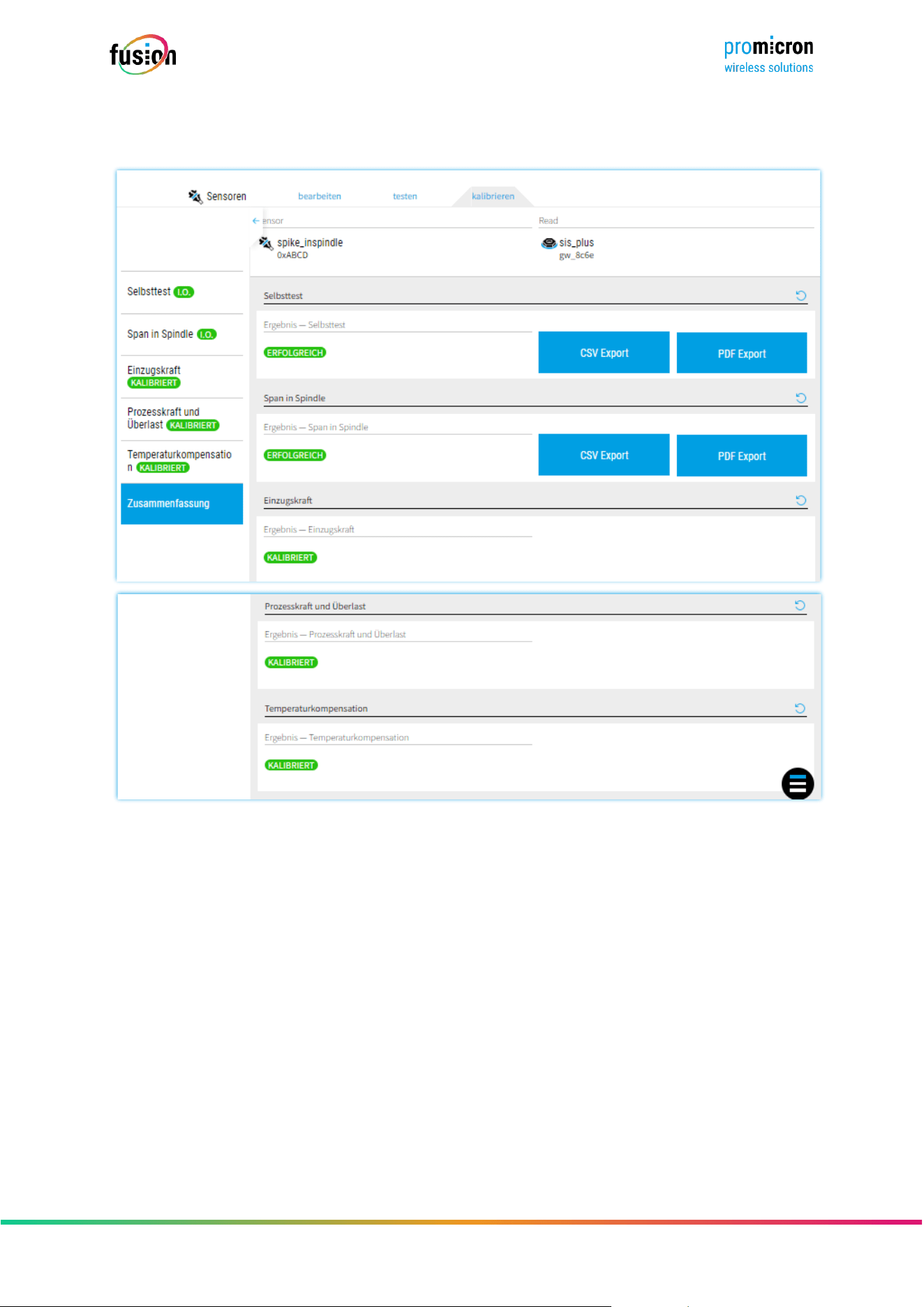
➔ Data recording must be activated via “Start recording”. Data recording ends automatically as soon
as a temperature difference of 10°C is reached compared to the initial temperature.
➔ Once the recording is nished, the motor spindle can be stopped.
➔ Clicking “Next” displays the result of the measurement.
➔

Seite 64 von 67
© pro-micron GmbH - Alle Rechte vorbehalten.
The graphs for the bending moment in the x and y directions as well as for the axial force are displayed
and compared with the measured temperature (yellow).
The entire measuring range shown in the graph is used to calculate the correction parameters. If the
measurement was started too early and the temperature does not yet show a clear change, the range can
be adjusted using the “Crop measurement start” option. The same applies to “Crop Measurement Stop” if
the measurement was ended too late. By default, the step size is set to 10 seconds.
After calculating the parameters for the temperature compensation, a green “CALIBRATED” symbol
appears in the “Temperature compensation” tab.
This is followed by “temperature compensation”. The calibration of the spike_inspindle is nished.
Seite 65 von 67
© pro-micron GmbH - Alle Rechte vorbehalten.
5.4.7 SUMMARY
An overview of the calibration results can be found in the “Summary” tab.
The results can be exported as a csv le or as a pdf le. System documentation is recommended. It also
forms the basis for service requests.
Seite 66 von 67
© pro-micron GmbH - Alle Rechte vorbehalten.
6 TROUBLESHOOTING
6.1 CONTACT SUPPORT
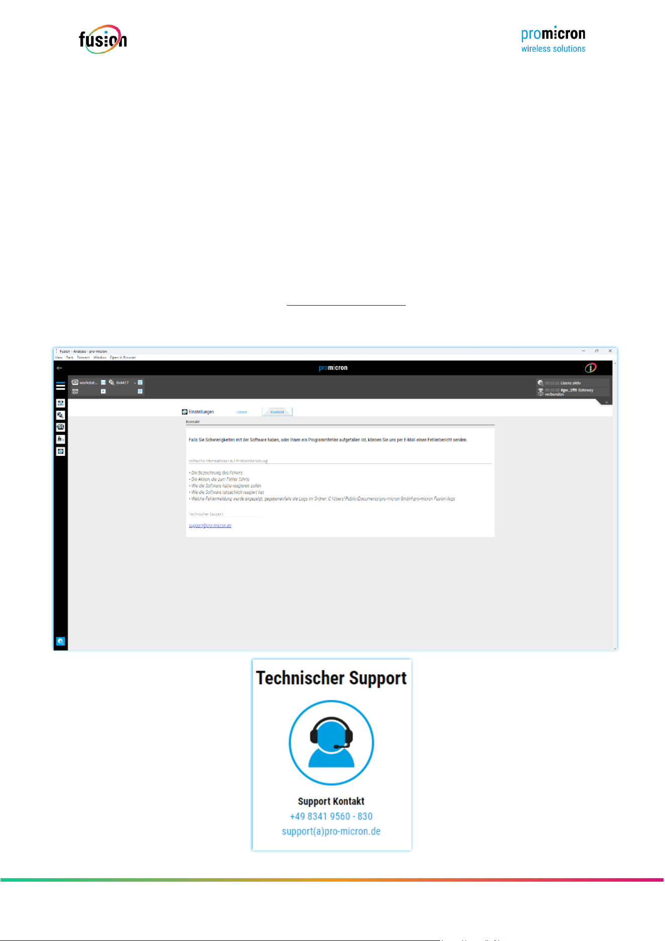
promicron support can be found under Settings
> Contact . The following information is relevant for a
comprehensive analysis:
▪ Self-test of the entire system
▪ Error label
▪ Brief description of the entire system (machine type, control, receiving device, software licenses)
This information can be sent by email to [email protected] or must be kept ready for telephone
inquiries.
Seite 67 von 67
© pro-micron GmbH - Alle Rechte vorbehalten.
7 GLOSSARY
Expression
Description
spike®
Measuring system with which the forces and
moments acting on the tool during machining
can be directly measured. Using the
measurement data, the machining process
can be diagnosed oine and monitored
online.
spike®_connect
The promicron base station for receiving
sensor data, commonly referred to as “Read”.
IPC
Industrial PC (IPC) used for tasks in the
industrial sector.
IBN
Installation
USB
Serial bus system for connecting a computer
to external devices .

