
MILWAUKEE TOOL
l
www.milwaukeetool.com
13135 W. LISBON RD., BROOKFIELD, WI 53005
Drwg. 4
BULLETIN NO.
54-40-2570
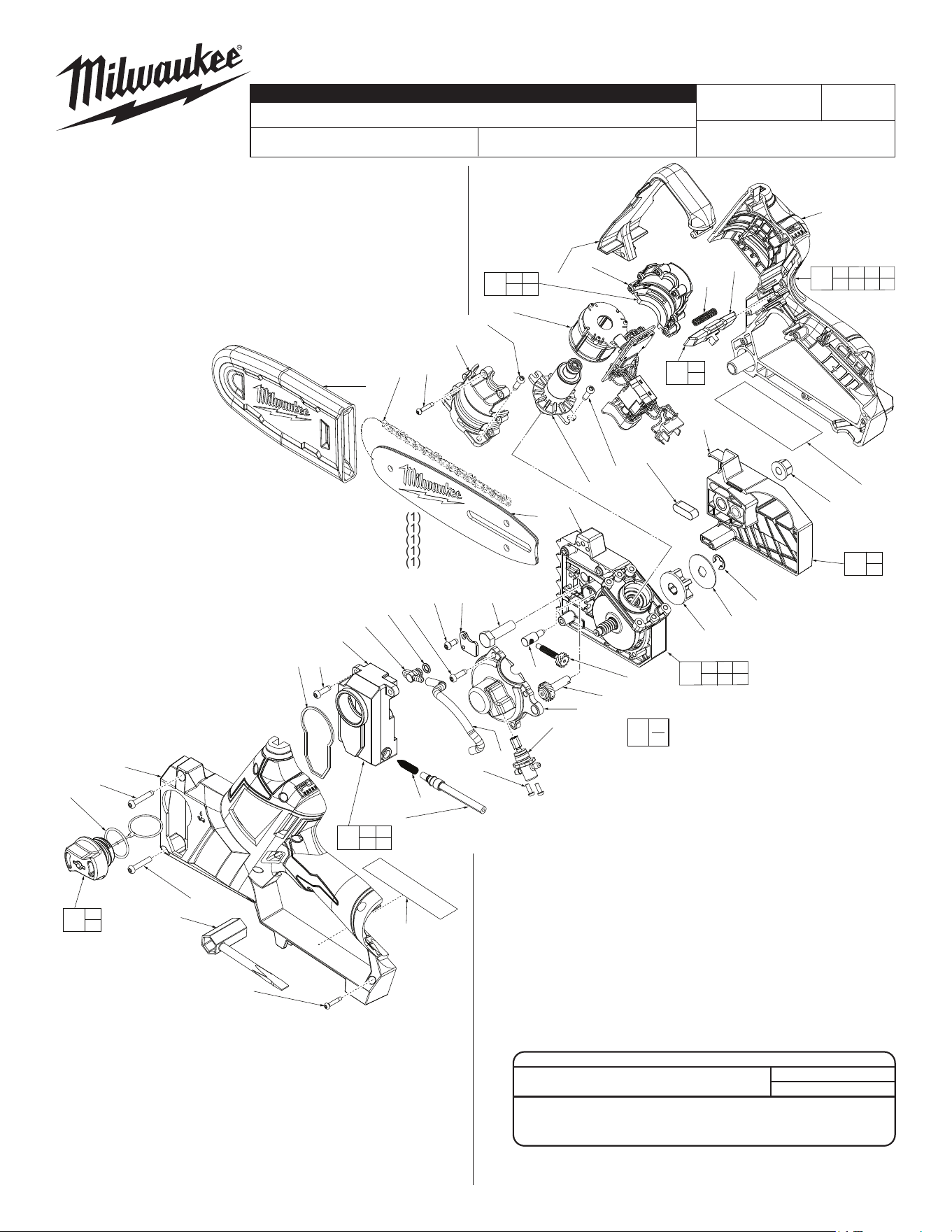
SERVICE PARTS LIST
CATALOG NO. 2527-20
REVISED BULLETIN
SPECIFY CATALOG NO. AND SERIAL NO. WHEN ORDERING PARTS
M12 FUEL™ Hatchet™ 6" Pruning Saw
STARTING
SERIAL NO.
DATE
Mar. 2023
WIRING INSTRUCTION
L34A
EXAMPLE:
Component Parts (Small #) Are Included
When Ordering The Assembly (Large #).
0
00
SEE PAGE 2
FIG. PART NO. DESCRIPTION OF PART NO. REQ.
4 34-40-9002 O-Ring (1)
6 05-78-5316 M4 x14mm Pan Hd. Taptite T-20 Scr. (10)
7 43-44-0022 Gasket (1)
8 --------------- Oil Tank (1)
9 45-76-3005 Inlet Tube (1)
10 --------------- Cone Spring (1)
11 05-78-0105 M4 x 10mm Pan Hd. Taptite T-20 Scr. (1)
12 44-66-0053 Retaining Plate (1)
13 45-76-2005 Outlet Tube (1)
14 42-86-0012 Connector (1)
15 34-40-4004 O-Ring (1)
16 05-89-8005 Chain Tensioner Main Screw (1)
17 05-89-2001 Chain Tensioning Post (1)
18 05-81-9001 Chain Tensioner Adjustment Screw (1)
19 05-85-0012 M8 x 28mm Hex Hd. Machine Screw (1)
20 49-16-2732 6" Chain (Accessory) (1)
21 49-62-2001 Scabbard (1)
22 49-16-2733 6" Guide Bar (Accessory) (1)
23 44-52-0018 Sealing Pad (1)
24 05-55-5001 M8 Flange Nut (1)
25 --------------- Chain Cover (1)
26 42-70-5268 E-Ring (1)
27 45-88-7001 Chain Washer (1)
28 45-44-0212 Sprocket (1)
42 05-81-1195 M3 x 6mm Pan Hd. Phillips Screw (2)
43 --------------- Motor Insulator Support - Right (1)
52 --------------- Motor Insulator Cover - Left (1)
53 06-82-6351 M3 x 16mm Pan Hd. ST T-10 Screw (15)
54 05-78-0870 M4 x 24mm Pan Hd. Taptite T-20 Scr. (1)
55 43-54-0023 Knuckle Guard (1)
56 --------------- Handle Cover - Left (1)
57 --------------- Handle Support - Right (1)
58 40-50-0209 Spring (1)
59 --------------- Lock-OButton (1)
60 45-96-1001 Wrench (1)
62 05-81-1275 M4 x 19mm Pan Hd. Taptite T-20 Scr. (1)
63 12-20-2533 Service Nameplate (1)
FIG. PART NO. DESCRIPTION OF PART NO. REQ.
64 10-20-8033 Warning Label (1)
80 42-52-3005 Oil Cap Assembly (1)
81 45-66-3005 Oil Tank Assembly (1)
82 43-72-0123 Chain Cover Kit (1)
83 --------------- Gearcase Assembly (1)
84 42-54-0210 Oil Pump Assembly (1)
85 --------------- Rotor Assembly (1)
86 23-16-0043 Motor Insulator Kit (1)
87 42-42-2010 Lock-OButtonkit (1)
88 14-20-1003 Electronics Assembly (1)
89 14-34-0135 Handle Kit (1)
90 --------------- Gearcase Cover Assembly (1)
91 05-78-0105 M3 x 10mm Flat Hd. Machine Screw (2)
92 14-30-2530 Gearcase Kit (1)
191211
15
14
6
(4x)
8
6
(2x)
7
4
54
56
22
83
85
91
(2x)
23
25
24
57
26
27
28
16
18
90
84
13
42
(2x)
10
9
62
60
53
(9x)
17
21
20
53
(6x)
52
6
(4x)
88
43
55
59
58
64
63
4
80
8 9
10
81
23
25
82
58
59
87
43 52
53
86
53 54 56 57
62 63 64
89
42 83 85
90 91
92
SCREW TORQUE SPECIFICATIONS
SEAT TORQUE
FIG. PART NO. WHERE USED (KG/CM) (IN/LBS)
6 05-78-5316 Gearcase Cover 25±3 22±3
11 05-78-0105 Gearcase 20±3 17±3
53 06-82-6351 Ground Plate 10±1 8±1
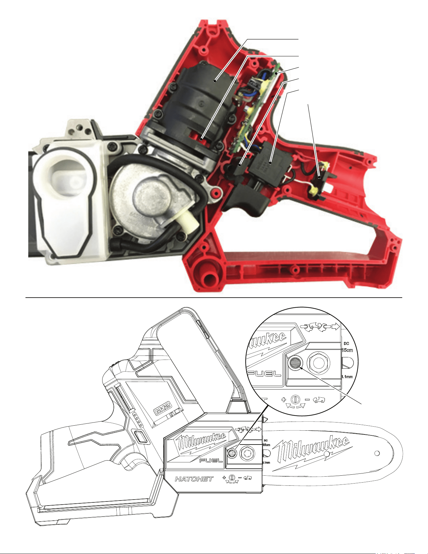
As an aid to reassembly, take notice of wire routings and position
in wire guides and traps while dismantling tool.
Be sure that all components of electronics kit are seated firmly
and squarely in housing recesses.
Avoid pinched wires, be sure that all wires and sleeves are
pressed completely down in wire traps.
Prior to securing housing cover onto the housing
support, be sure that there are no interferences.
Before installing the battery, check for proper
functionality of shuttles and triggers.
Install battery and depress switch triggers to
assure tool is operating properly.
Stator Assembly is contained inside
Motor Insulator
Rotor Assembly is contained inside Stator
Control Board
Lock-Off Shuttle
On-Off Switch
Battery Terminal Block
1. Remove battery prior to doing any adjustments to tool!
2. The chain can be adjusted but using the Chain Tensioner Adjustment Screw. Chain
should be tensioned to 18-22 kgf/cm (15-19 in/lbs) by using a torque screwdriver.
3. Manually check chain by pulling away from guide bar approximately 3mm (1/8”),
chain should snap back. Chain should be able to be pulled without difficulty.
Chain Tensioner
Adjustment
Screw (18)
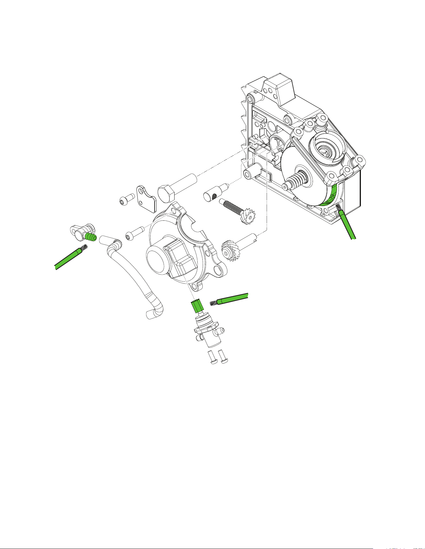
LUBRICATION
Apply 0.2g of bar oil to
the connector (14).
Apply 0.5g of type ”J” grease (49-08-4220) to
the gear.
Apply 8g of type ”J” grease (49-08-4220) to
the cavity.