THIS INSTRUCTION BOOKLET CONTAINS IMPORTANT SAFETY INFORMATION.
PLEASE READ AND KEEP FOR FUTURE REFERENCE.
Date 2020-07-16 Rev. 0001-A
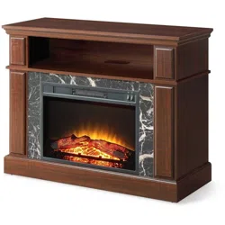
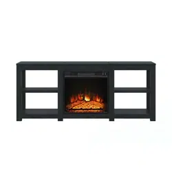
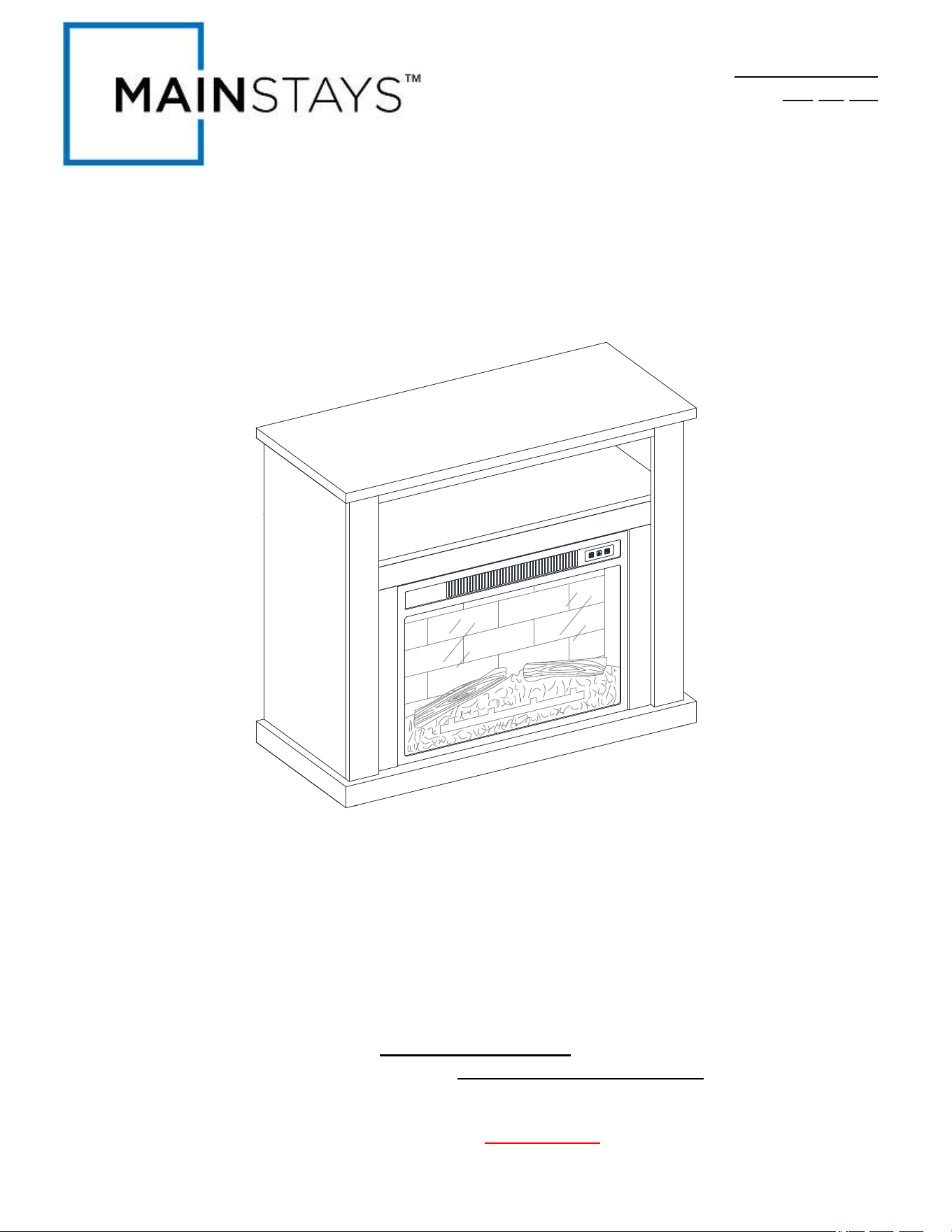
Media Fireplace Console
Stock # MSD036158813001 Black Finish
# MSD036158813002 Dark Cherry Finish
ADULT ASSEMBLY REQUIRED
If you have any questions regarding assembly or if parts are missing, DO NOT return this item to the
store where it was purchased. Please call our customer service number and have your instructions
and parts list ready to provide the model name, part name or factory number:
866-942-5362
Pacific Standard Time: 8:30 a.m. - 4:30 p.m., Monday - Friday
Or visit our web site 24 hours a day, 7 days a week for product assistance at
www.whalenstyle.com
Or e-mail your request to parts@whalenfurniture.com
LOT NUMBER:
DATE PURCHASED: / /
2
MANUFACTURER: Whalen Furniture Manufacturing
CATALOG: Media Fireplace Console
MODEL # MSD036158813001 / MSD036158813002
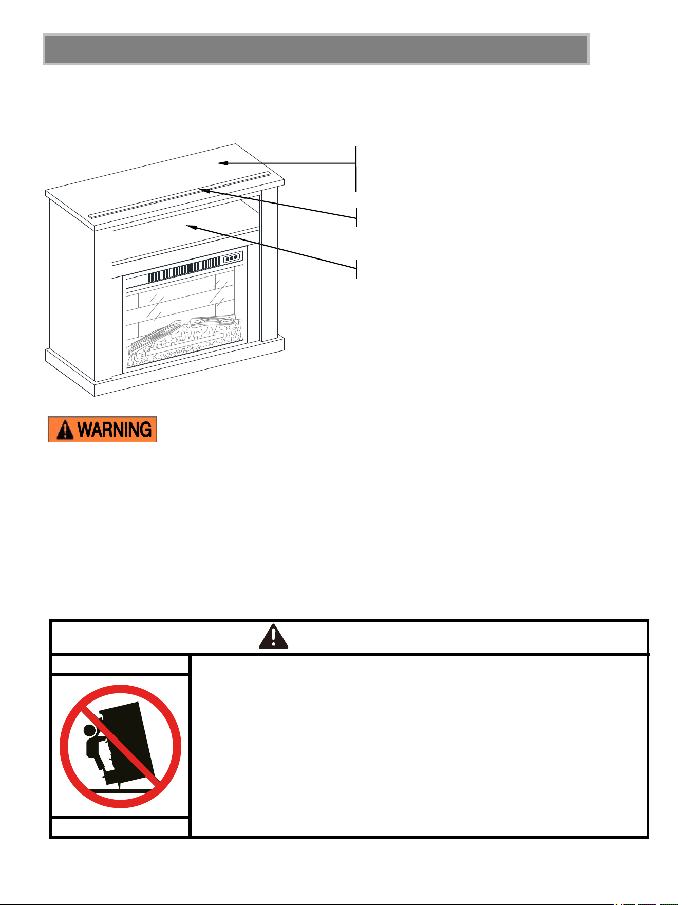
M A X I M U M R E C O M M E N D E D W E I G H T L O A D S
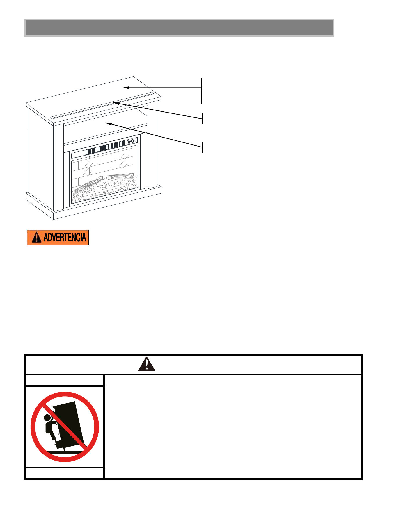
PLACE TV BEHIND THE STOPPER
FITS UP TO MOST 42” DIAGONAL FLAT
PANEL TVs
MAXIMUM LOAD 50 lb. (22.7 kg)
MAXIMUM LOAD 50 lb. (22.7 kg)
THIS UNIT IS NOT INTENDED FOR USE WITH CRT TVS. USE ONLY WITH FLAT
PANEL TVS AND AUDIO/VIDEO EQUIPMENT MEETING RECOMMENDED SIZE AND WEIGHT LIMITS.
NEVER USE WITH LARGER/HEAVIER THAN RECOMMENDED FLAT PANEL TVS OR EQUIPMENT. TO
AVOID INSTABILITY, PLACE FLAT PANEL TV IN THE CENTER OF THE UNIT; THE BASE OF THE
TELEVISION MUST BE ABLE TO REST ON THE SUPPORTING SURFACE OF THE UNIT WITHOUT
OVER-HANGING THE EDGES. IMPROPERLY POSITIONED FLAT PANEL TVS, OR FLAT PANEL TVS
INCLUDING OTHER EQUIPMENT THAT EXCEED RECOMMENDED SIZE AND WEIGHT LIMITS
COULD FALL OFF OR BREAK THE UNIT, CAUSING POSSIBLE SERIOUS INJURY. FOR USE WITH
TELEVISIONS WEIGHING 50 LBS (22.7 KG) OR LESS. USE WITH HEAVIER TELEVISIONS MAY
RESULT IN INSTABILITY CAUSING TIP OVER RESULTING IN DEATH OR SERIOUS INJURY.
Children have died from furniture tip-over.
To reduce the risk of furniture tip-over:
ALWAYS install tip-over restraint provided.
FOR use with televisions weighing 50 lbs or less. Use with heavier televisions
may result in instability causing tip-over resulting in death or serious injury.
NEVER allow children to stand, climb or hang on drawers, doors, or shelves.
NEVER open more than one drawer at a time.
Place heaviest items in the lowest drawers.
Use of tip-over restraints may only reduce, but not eliminate, the risk of
tip-over.
WARNING
3
IMPORTANT
Before you begin: Open, identify and count all parts prior to assembly. Lay out parts on a flat and non-
abrasive surface. You will need the parts identified on page 4 and 5 of this instruction manual.
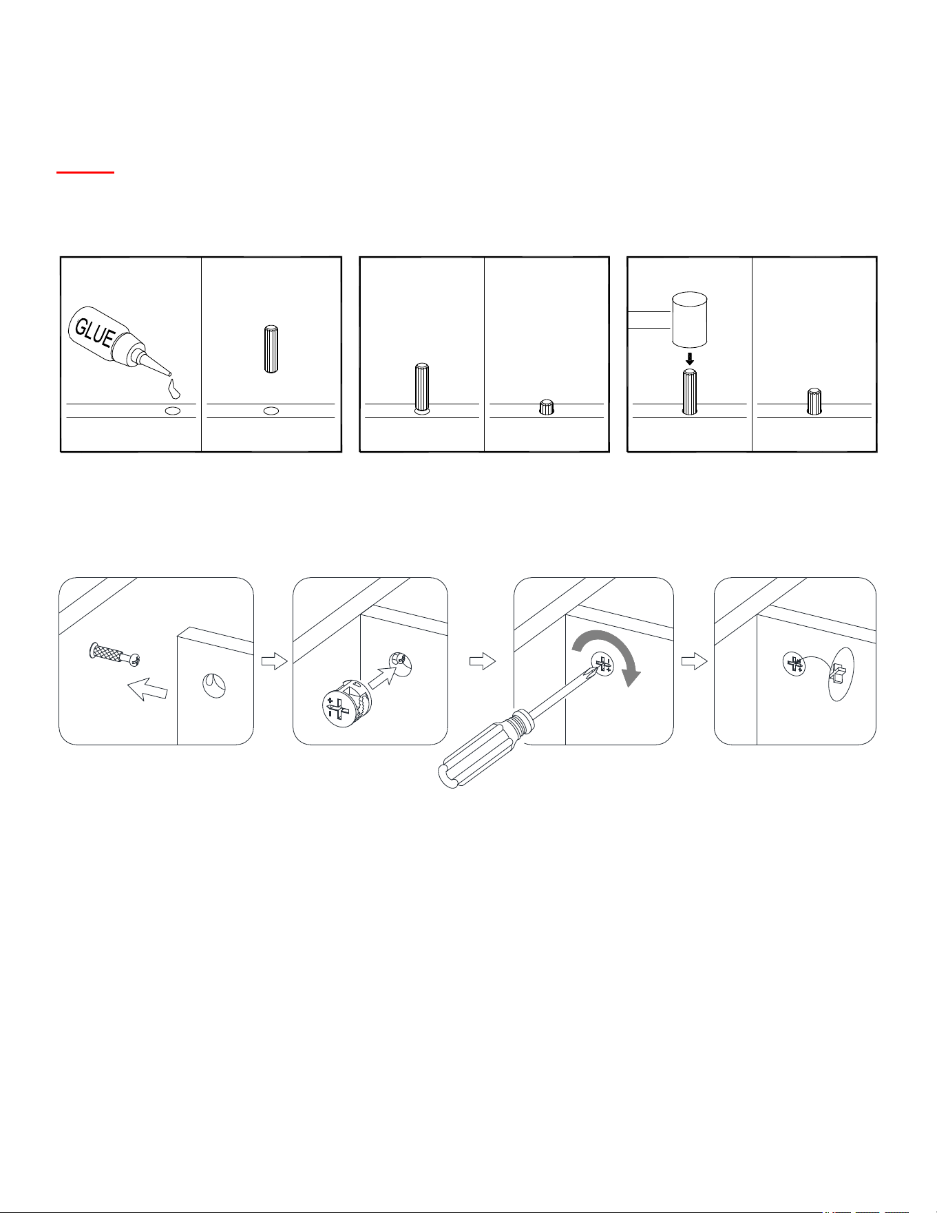
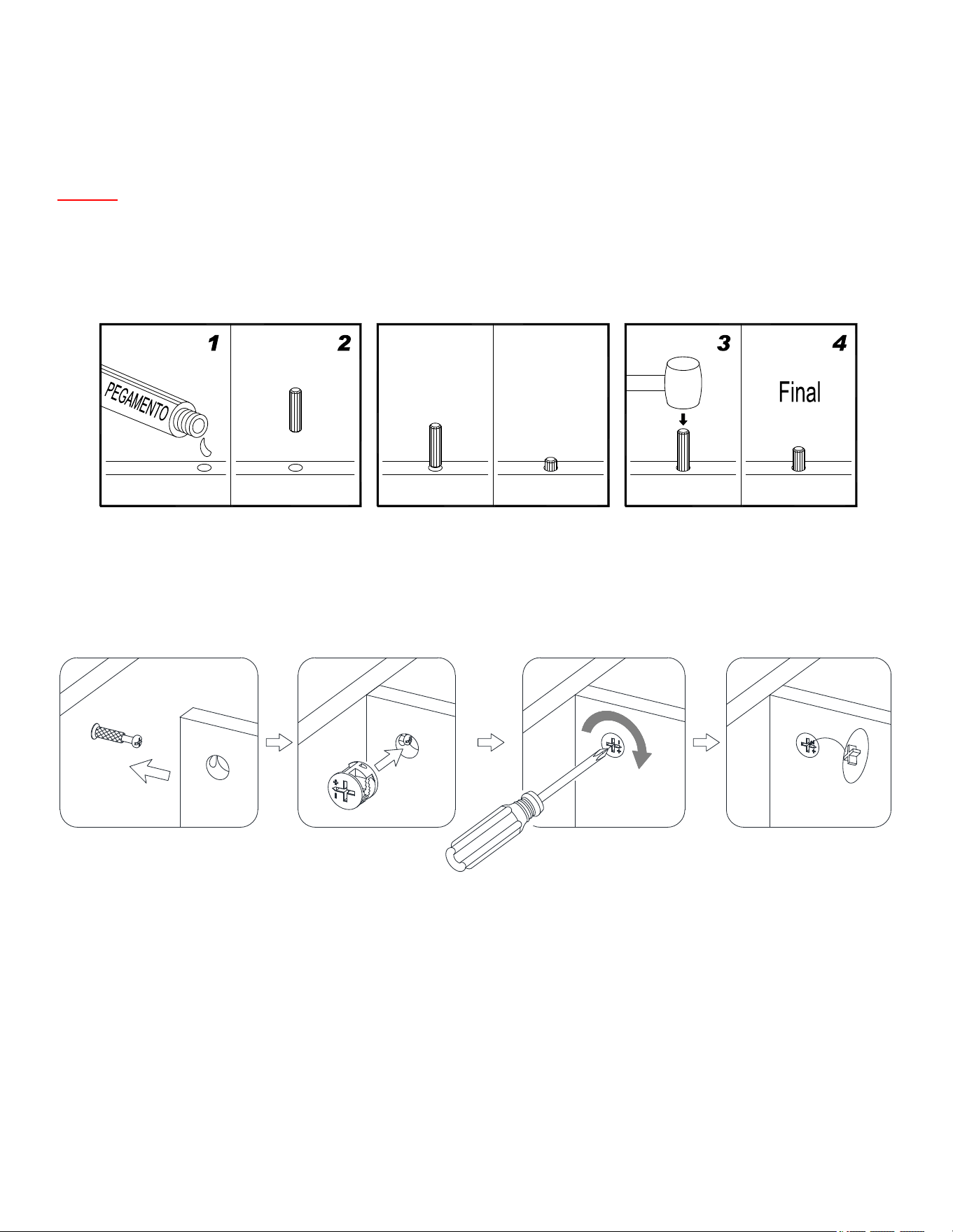
NOTE: IT IS VERY IMPORTANT TO USE GLUE WITH DOWELS. EXCESS GLUE CAN BE WIPED
OFF WITH DAMP CLOTH.
Insert the Dowel at least half way by tapping lightly with a rubber mallet, IF NECESSARY.
CAM LOCK SYSTEM OPERATION
HOW THE KNOCK DOWN (KD) ASSEMBLY SYSTEM WORKS
1. Screw the Cam Bolt into the threaded inserts on the panel. Connect both panels together; making sure Cam
Bolt goes into the pre-drilled hole on the end of panel for Cam Lock.
2. Insert the Cam Lock into the pre-drilled large hole on the panel. Make sure the arrow on the face of Cam
Lock faces out and points towards Cam Bolt.
3. Take a Phillips screwdriver and rotate the Cam Lock clockwise to lock the Cam Bolt in place.
4. Plug the Cam Lock Cover into the cross slot of the Cam Lock to conceal the Cam.
You are now ready to assemble the fireplace.
X
X
FINAL
1 2 43
1
2
3
4
4
Parts and Hardware List
Please read completely through the instructions and verify that all listed parts and hardware are present
before beginning assembly.
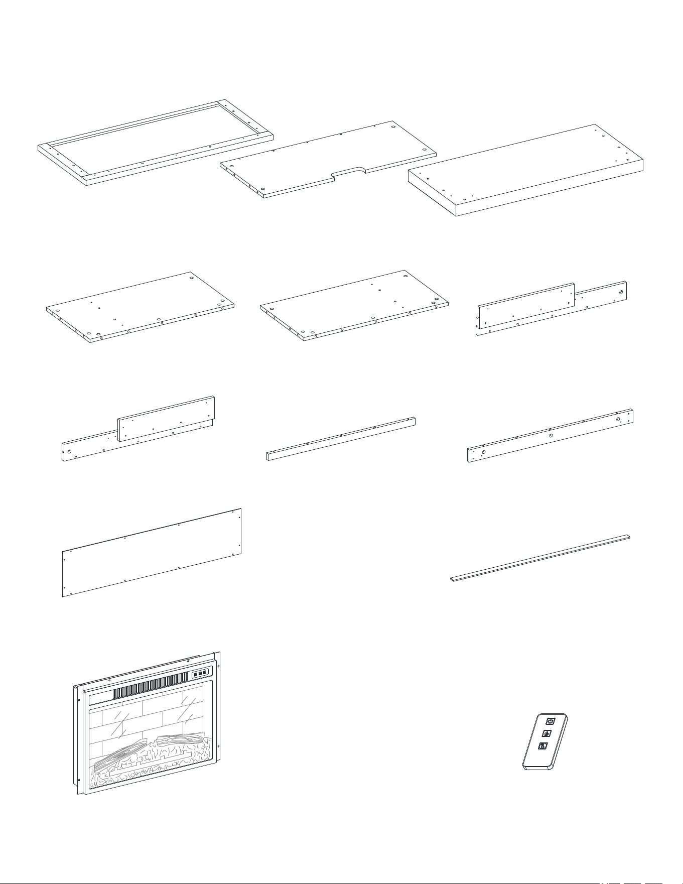
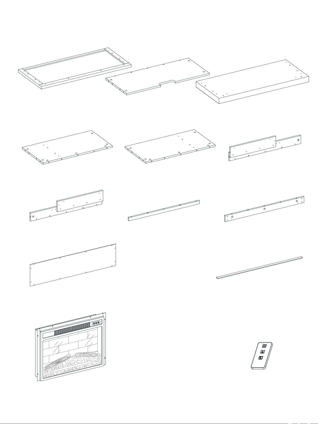
A- Top Panel (Qty. 1) B- Media Shelf (Qty.1) C- Base (Qty. 1)
D- Left Side Panel (Qty. 1) E- Right Side Panel (Qty. 1) F- Left Front Molding (Qty. 1)
G- Right Front Molding (Qty. 1) H- Upper Front Molding (Qty.1) I- Center Crossbar (Qty.1)
J- Back Panel (Qty. 1) K- Stop Rail (Qty. 1)
Fireplace Insert (Qty. 1) Remote Control with Battery (Qty. 1)
5
Parts and Hardware List
Please read completely through the instructions and verify that all listed parts and hardware are present
before beginning assembly.
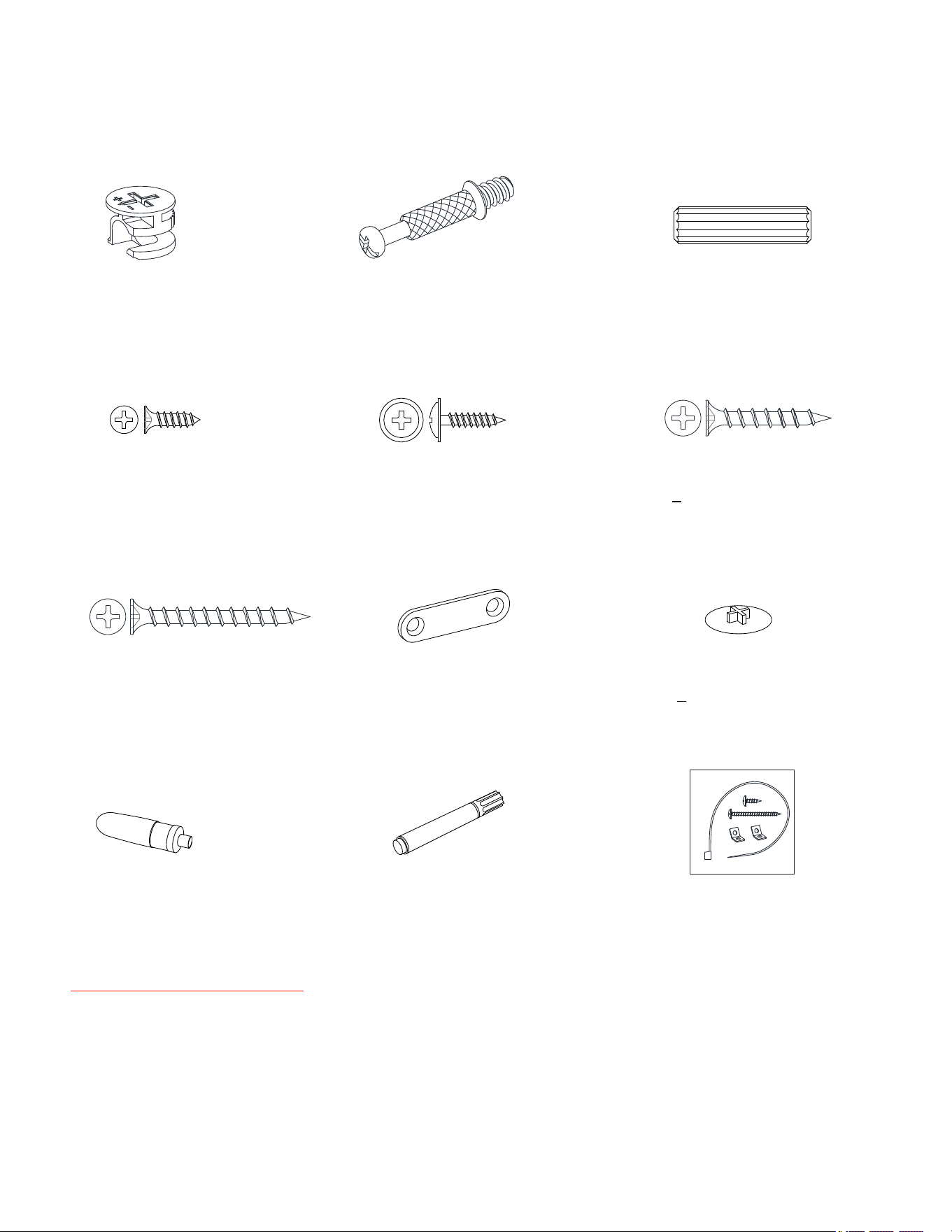
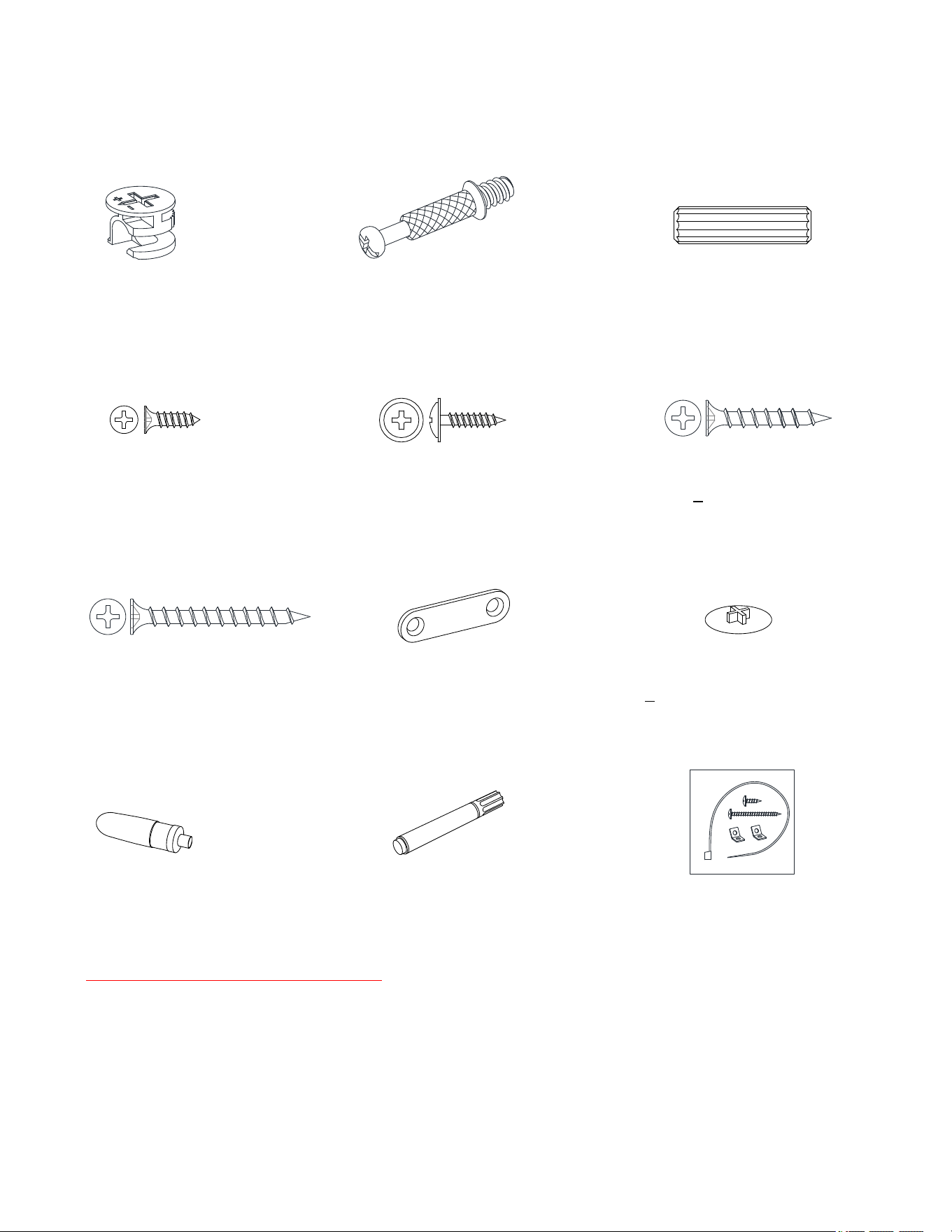
(1) Cam Lock (2) Cam Bolt (3) M8 x 30 mm Wood Dowel
(Qty. 23+1 extra) (Qty. 23+1 extra) (Qty. 22+1 extra)
(4) M3.5 x 12 mm Screw (5) M3.5 x 15 mm Washer Head Screw (6) M4 x 28 mm Screw
(Qty. 4+1 extra) (Qty. 12+1 extra) (Qty. 4+1 extra)
(7) M4 x 40 mm Screw (8) Mending Plate (9) Cam Lock Cover
(Qty. 5+1 extra) (Qty. 2) (Qty. 6+1 extra)
Glue (Qty. 1) Touch-up Pen (Qty. 1) Tipping Restraint Hardware Kit (Qty. 2)
(Included in plastic bag)
Tools required (not included): Phillips screwdriver, stud finder, pencil, tape measure, power drill and 1/8 in
drill bit.
6
Assembly Instructions
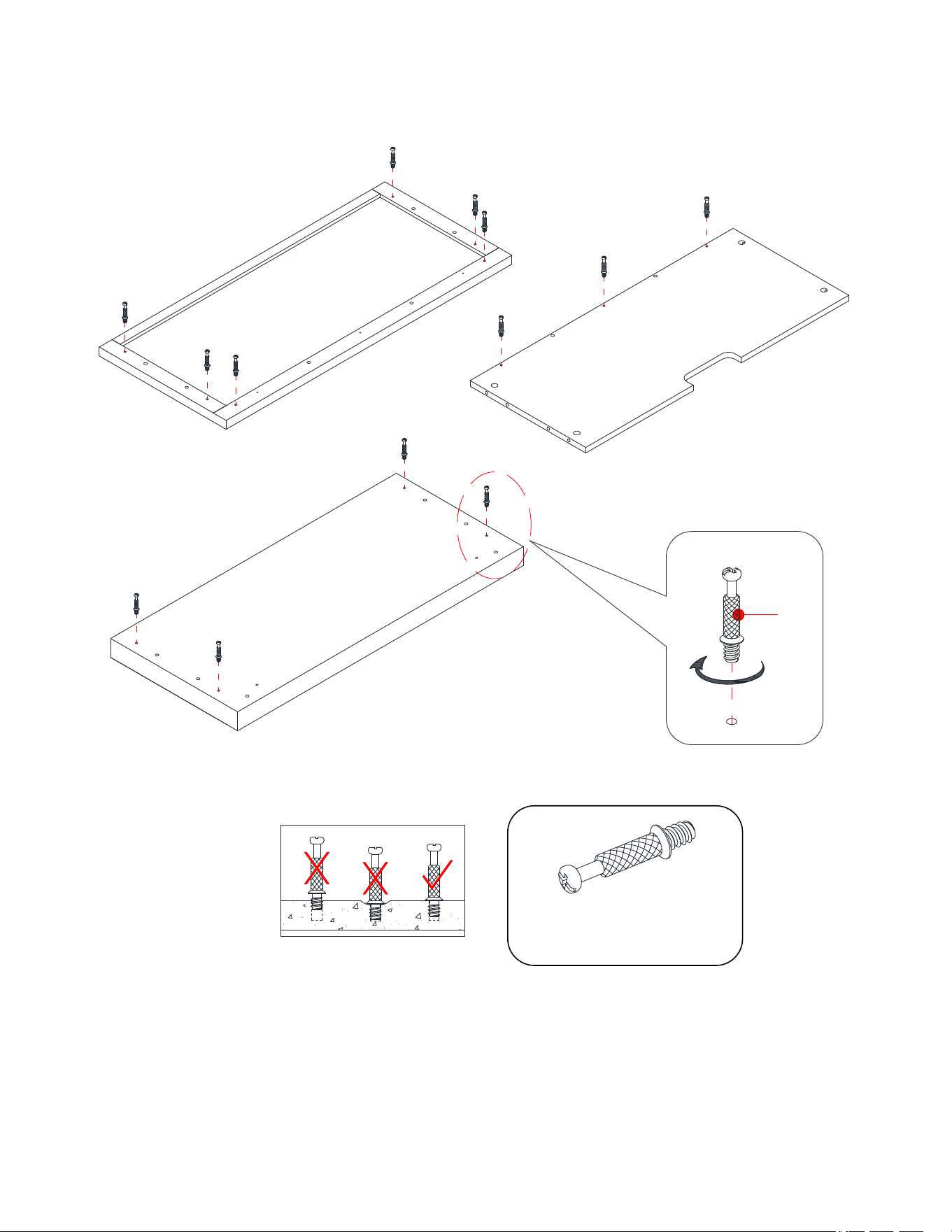
1. Unpack the unit and confirm that you have all the hardware and required parts. Assemble the unit on a
carpeted floor or the empty carton to avoid any scratch.
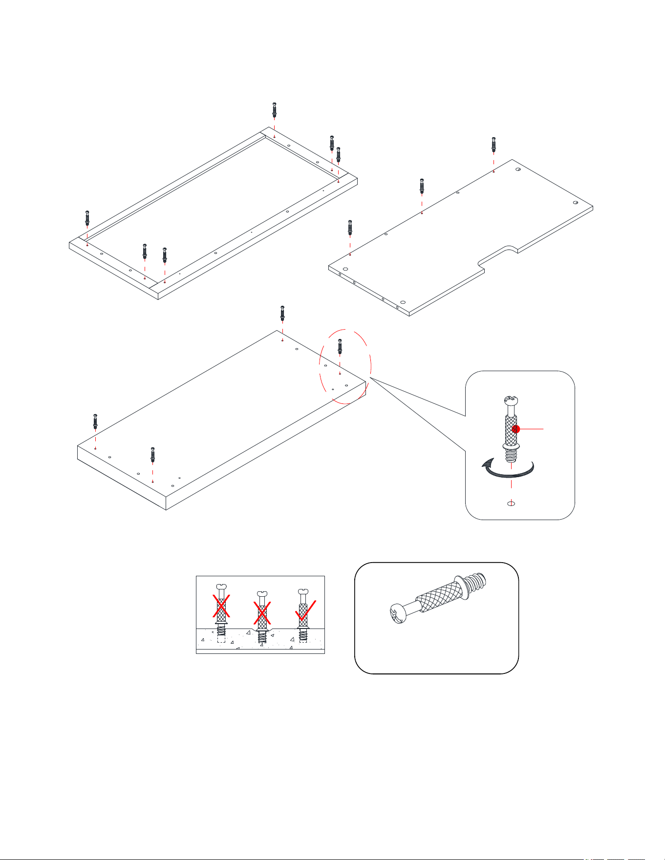
2. Securely screw the Cam Bolts (2) into the designated small holes on the Top Panel (A), Media Shelf (B)
and Base (C) with a Phillips screwdriver. DO NOT over tighten the cam bolts.
② x 13
2
A
B
C
7
Assembly Instructions
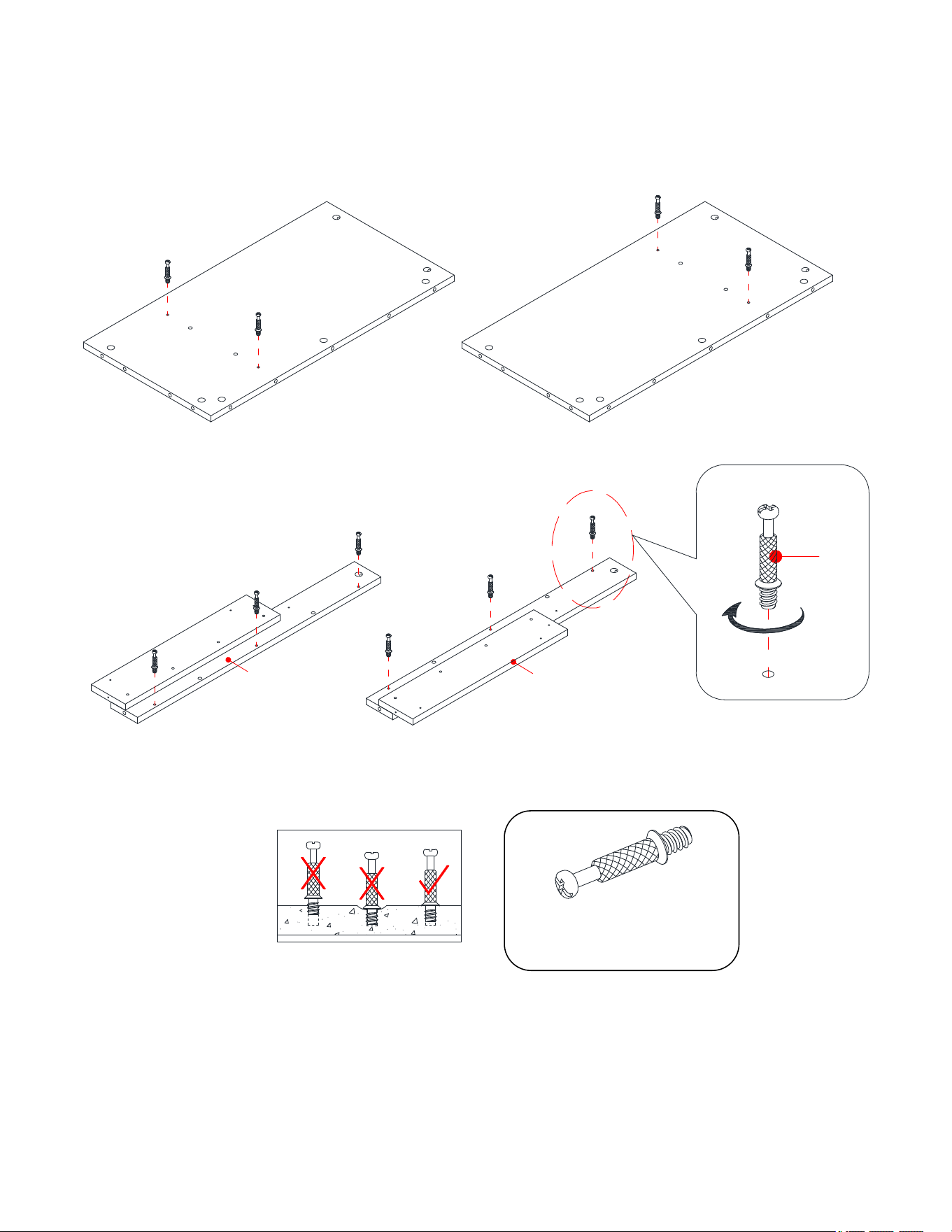
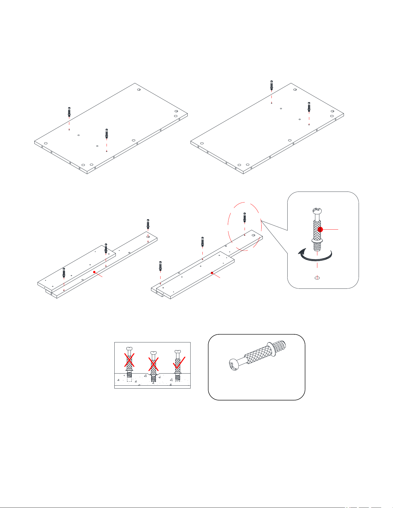
3. Continue to screw the Cam Bolts (2) into the designated small holes on the Side Panels (D and E) and Front
Moldings (F and G).
2
D
E
G
F
② x 10
8
Assembly Instructions
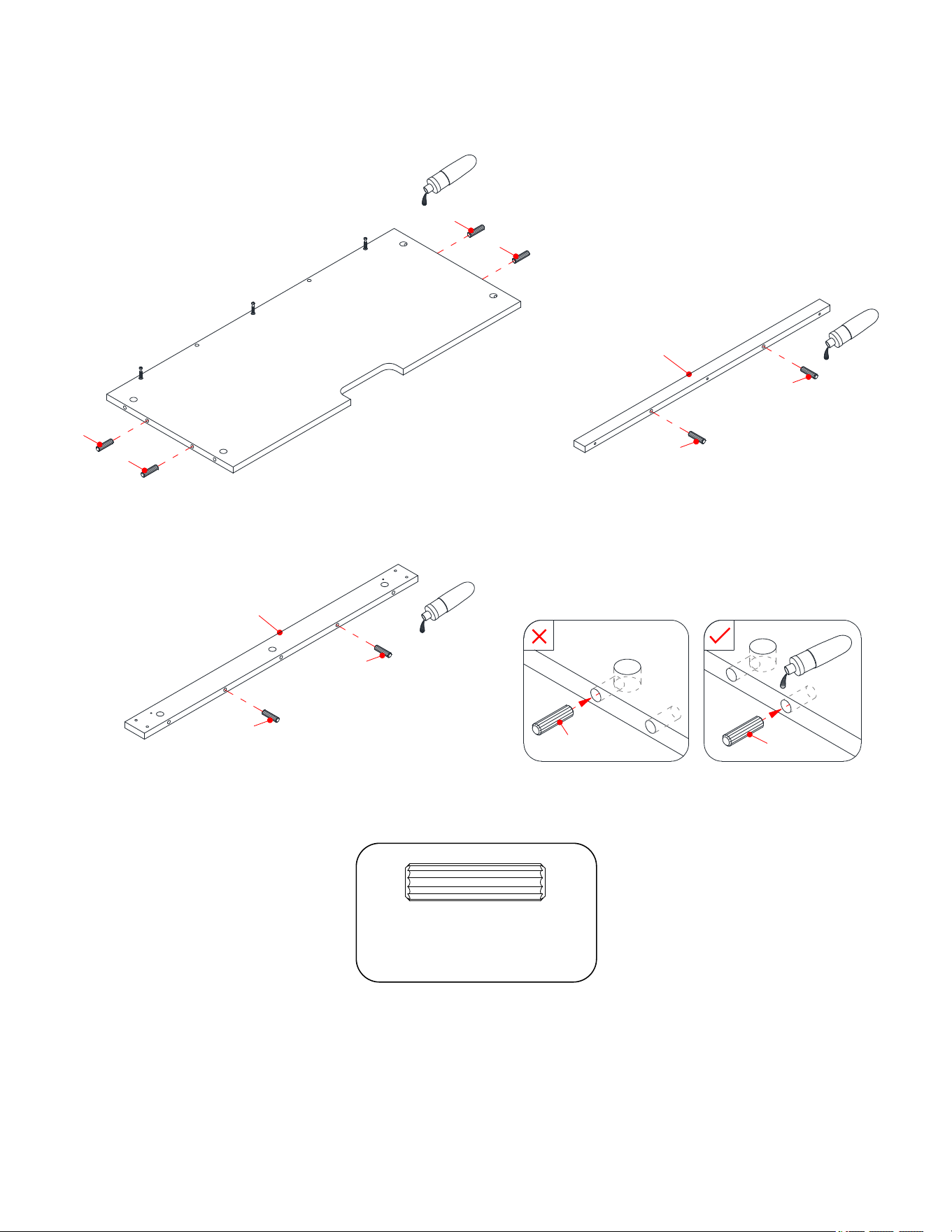
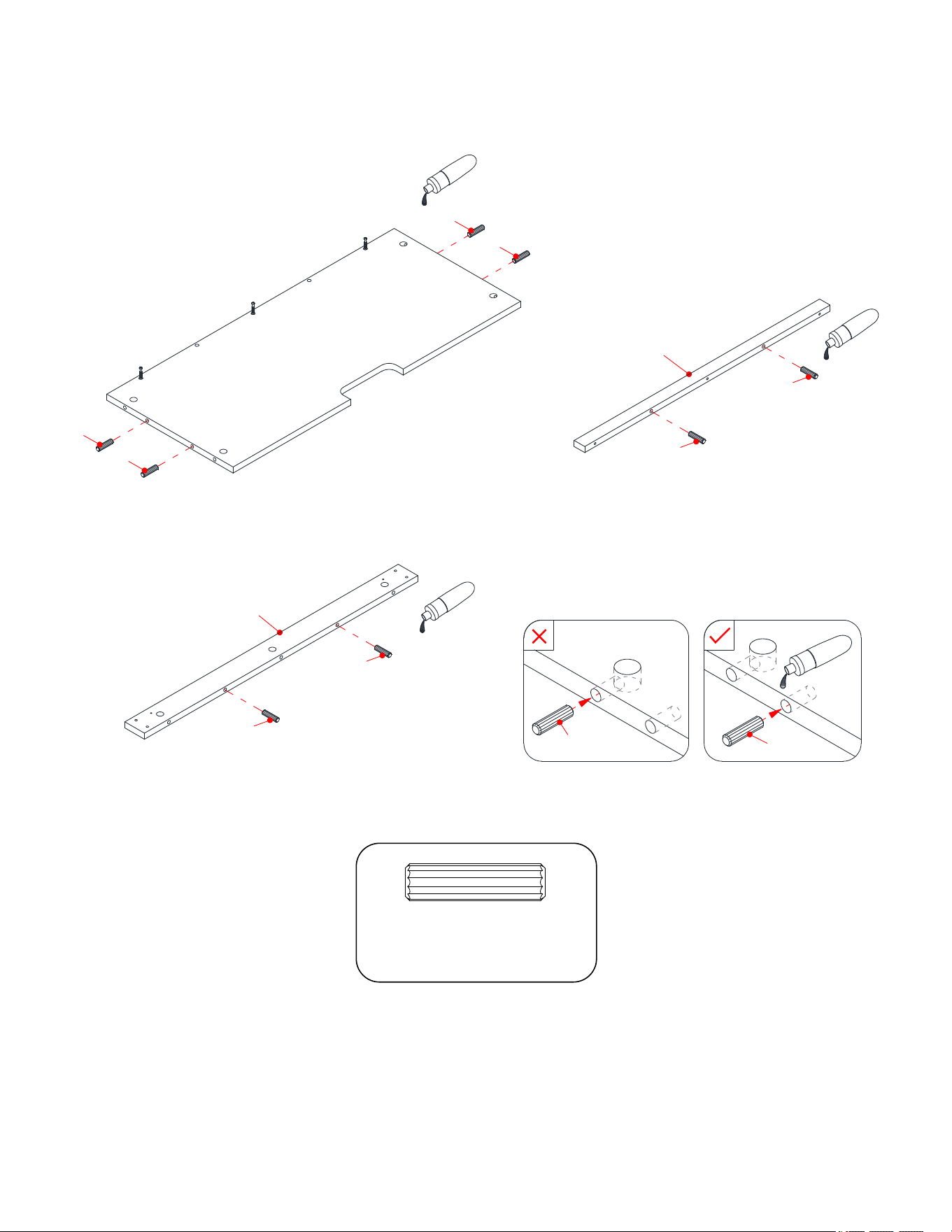
4. Insert the 30 mm Wood Dowels (3) into the inner holes on the Media Shelf (B), Upper Front Molding (H)
and Center Crossbar (I). Make sure that you use a small amount of glue with both ends of all dowels.
③ x 8
3
3
3
3
3
3
3
3
3
3
H
I
B
9
Assembly Instructions
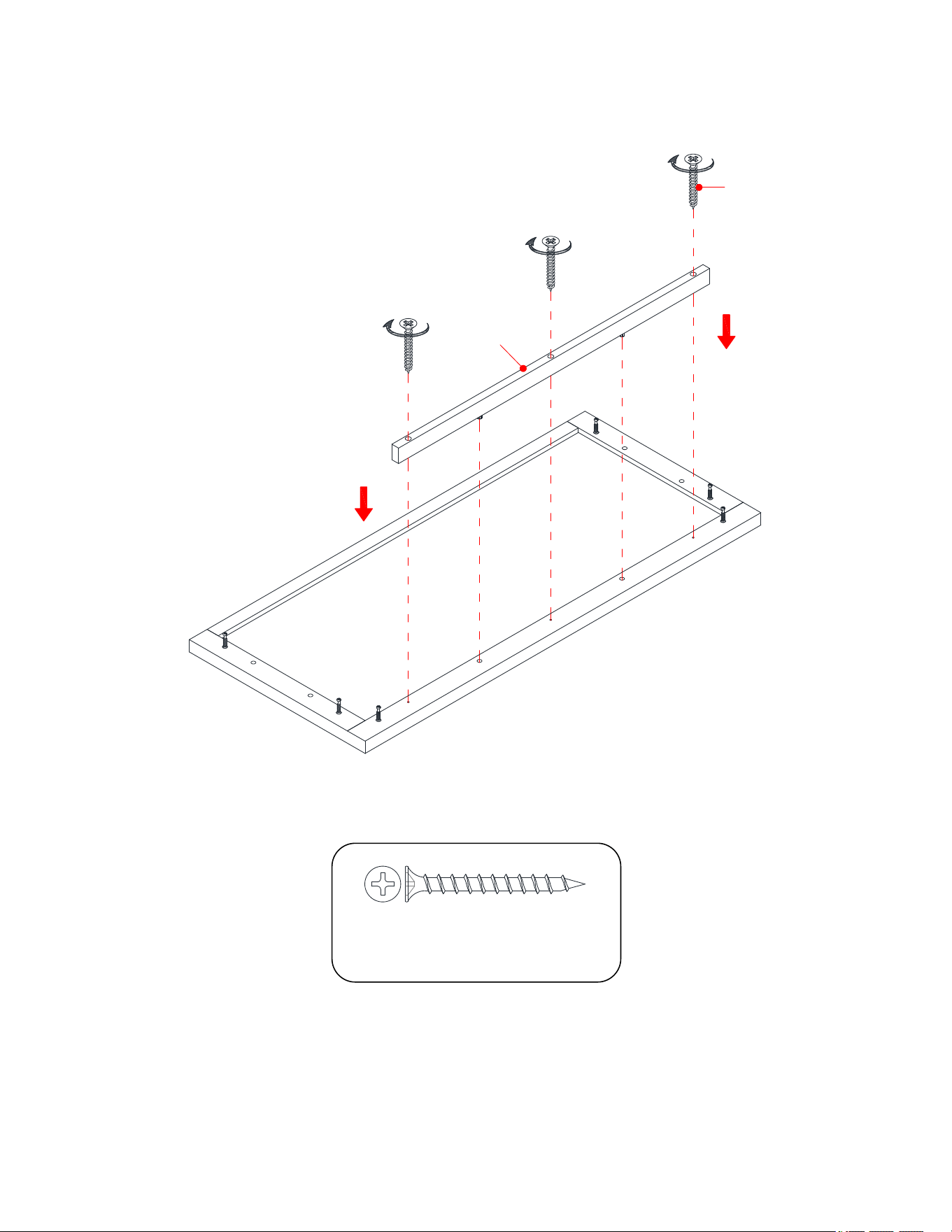
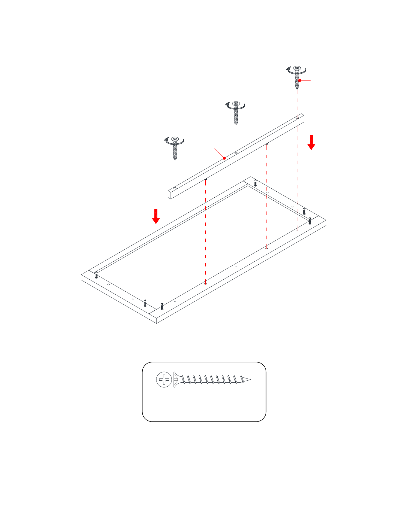
5. Align and attach the Upper Front Molding (H) to the front of Top Panel (A) with three 40 mm Screws (7).
⑦ x 3
7
H
A
10
Assembly Instructions
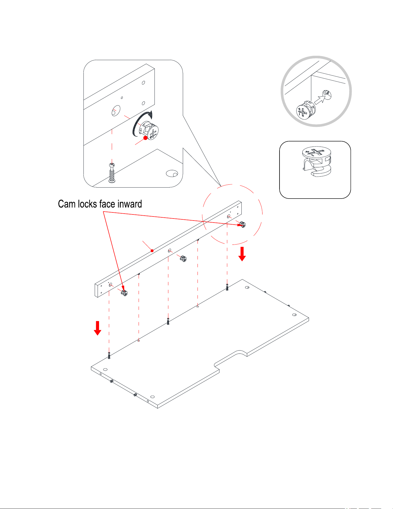
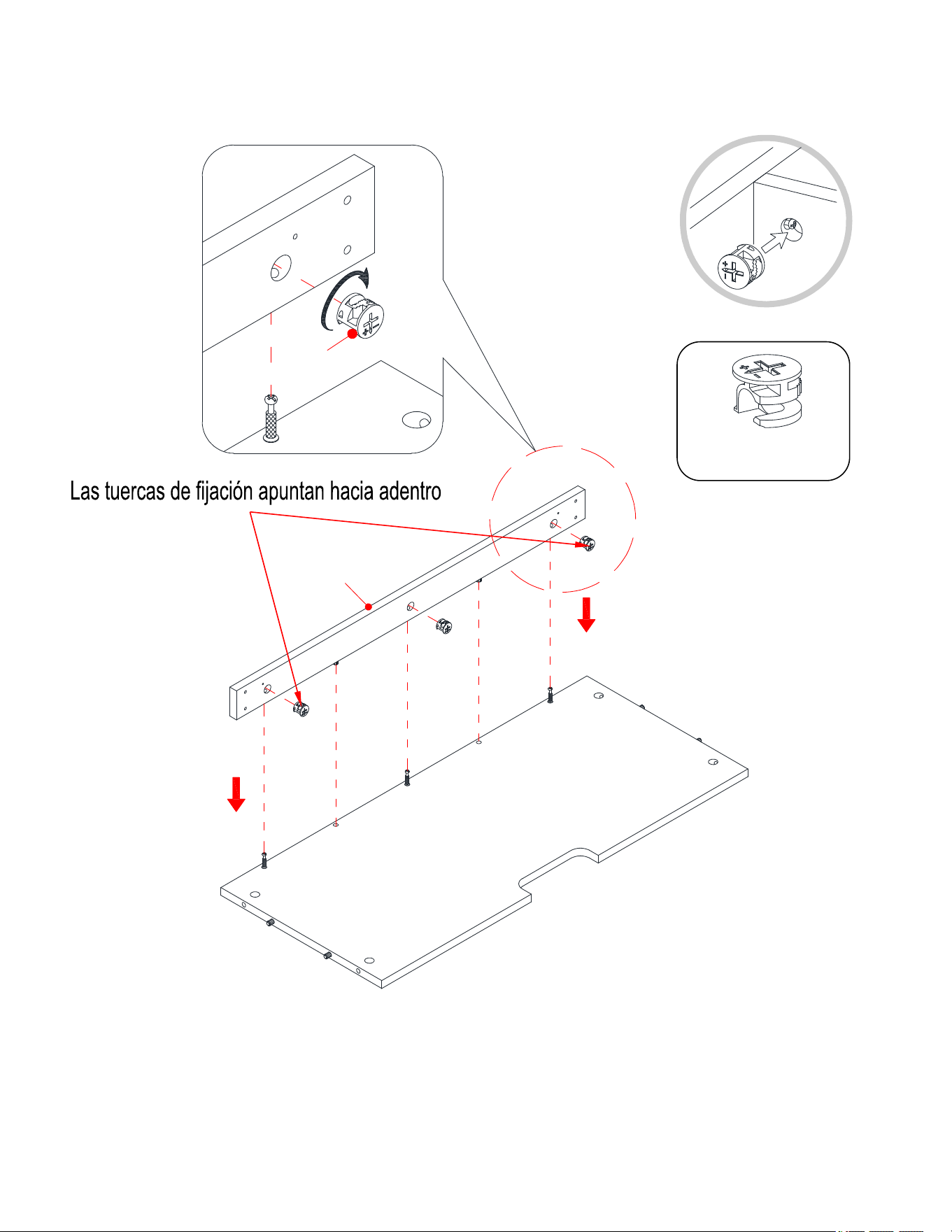
6. Align and attach the Center Crossbar (I) to the Media Shelf (B) by engaging three Cam Locks (1)
(Refer to page 3 on Cam Lock system operation supplement).
① x 3
1
B
I
B
I
11
Assembly Instructions
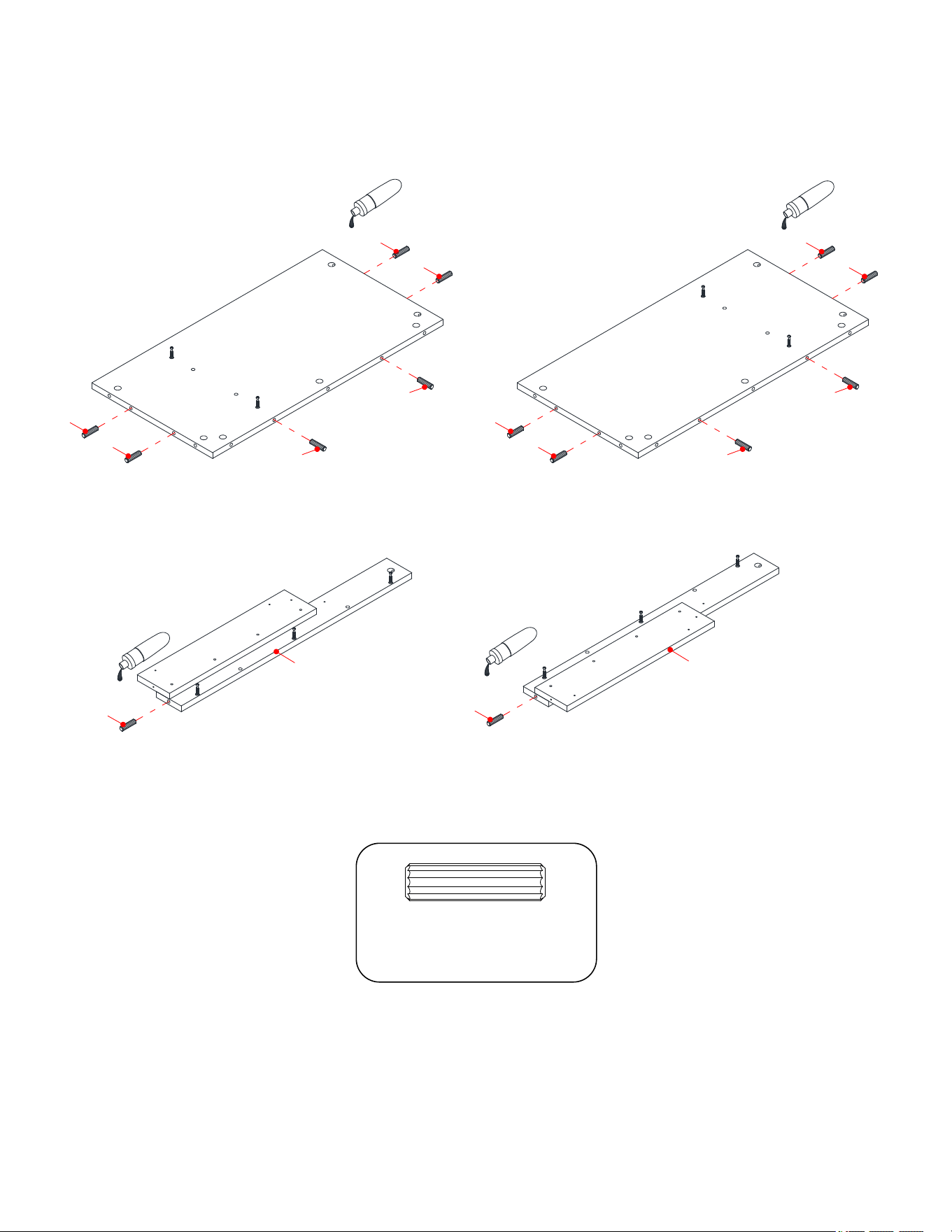
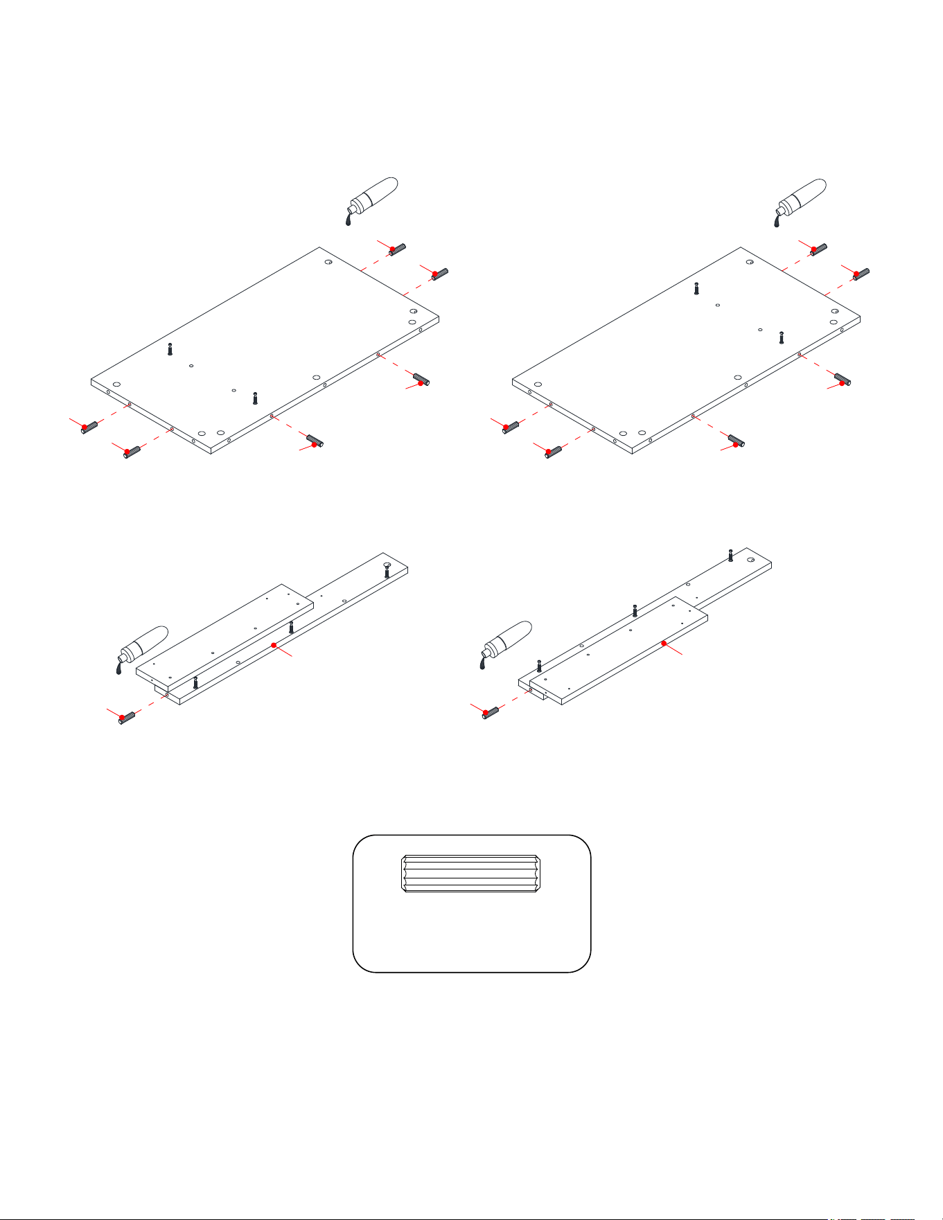
7. Insert the 30 mm Wood Dowels (3) into the inner holes on the Side Panels (D and E) and Front Moldings (F
and G). Make sure that you use a small amount of glue with both ends of all dowels.
③ x 14
3
33
3
3
3
3
3
D
E
3
3
3
3
3
F
G
3
12
Assembly Instructions
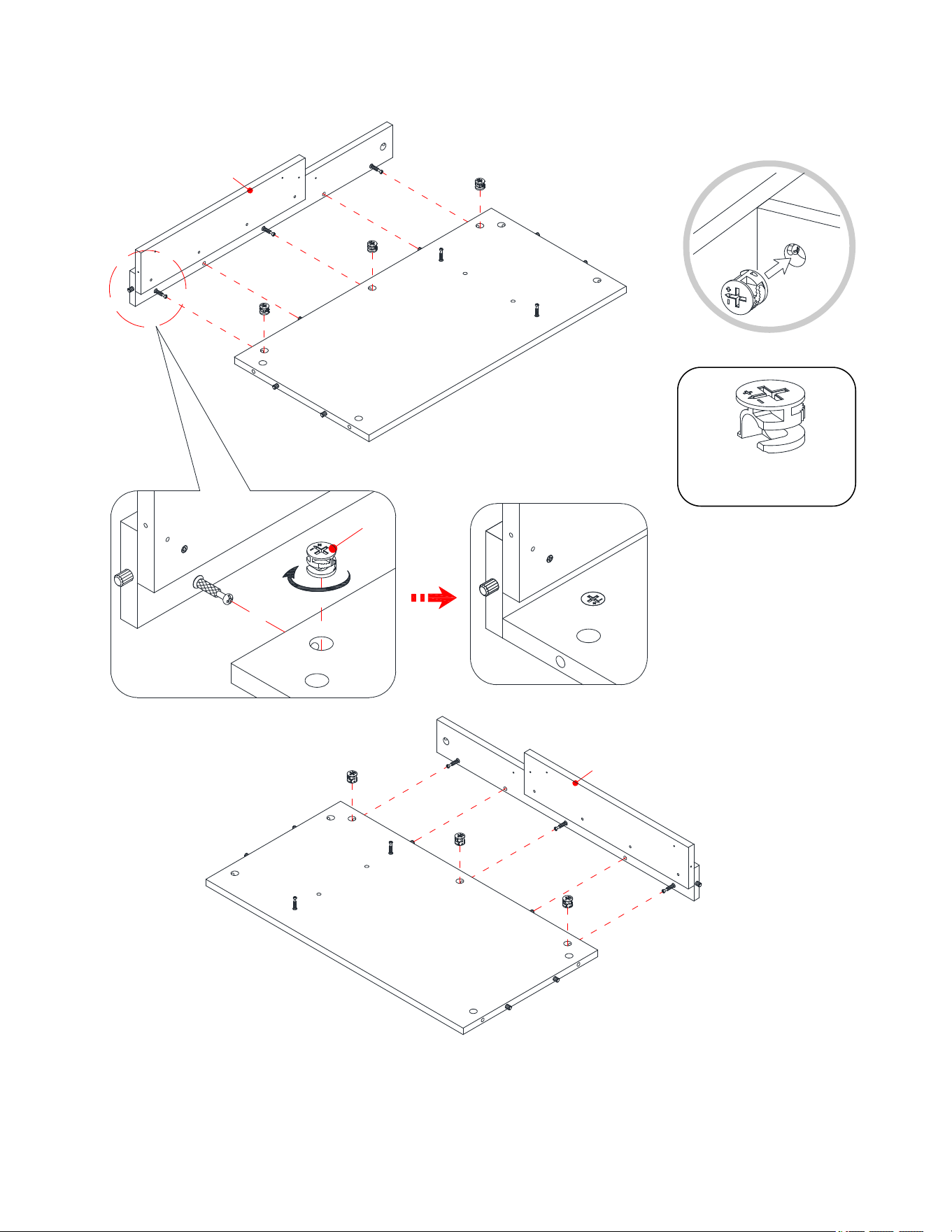
8. Align and attach the Left Front Molding (F) to the Left Side Panel (D) by engaging three Cam Locks (1).
9. Repeat the same procedure to attach the Right Front Molding (G) to the Right Side Panel (E).
① x 6
1
D
E
F
G
F/G
D/E
13
Assembly Instructions
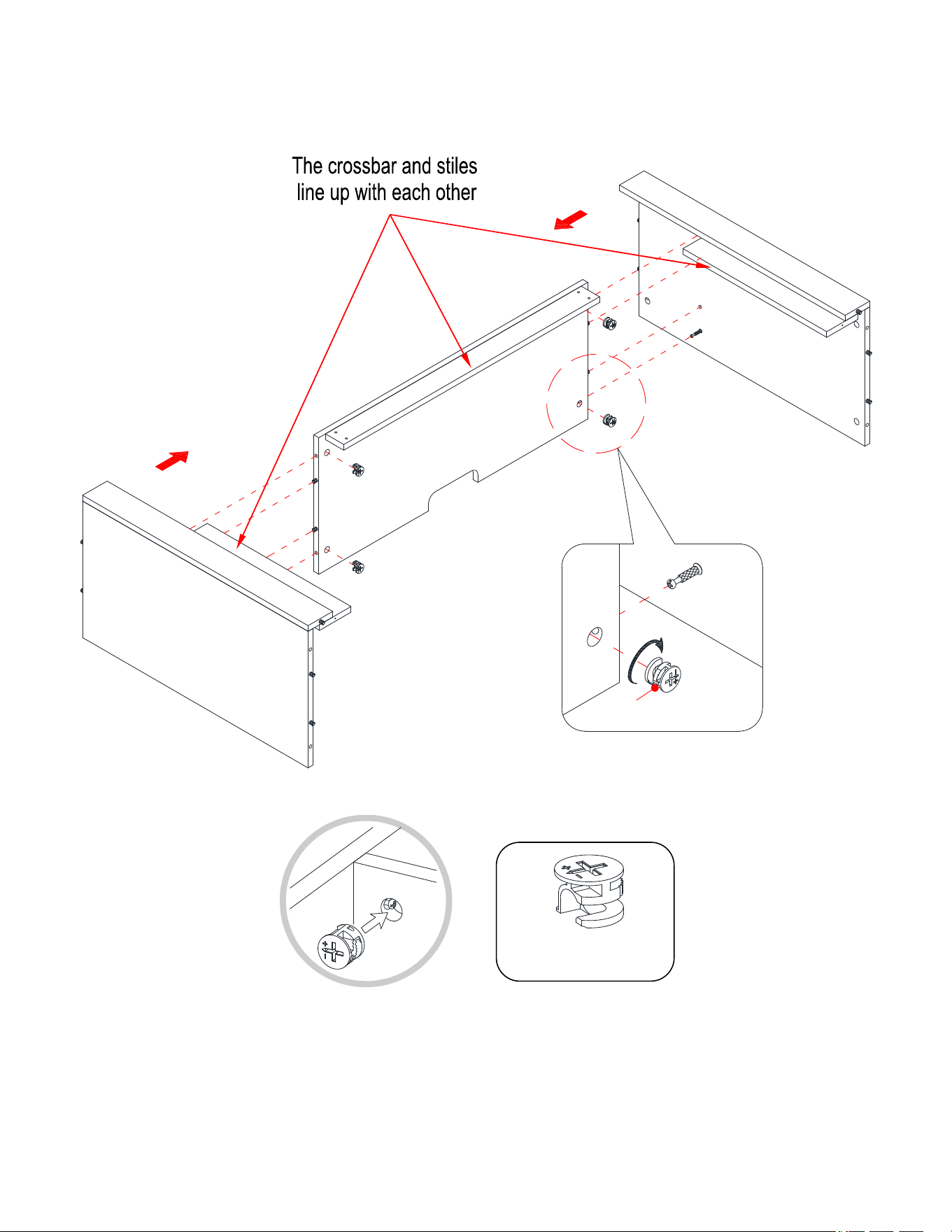
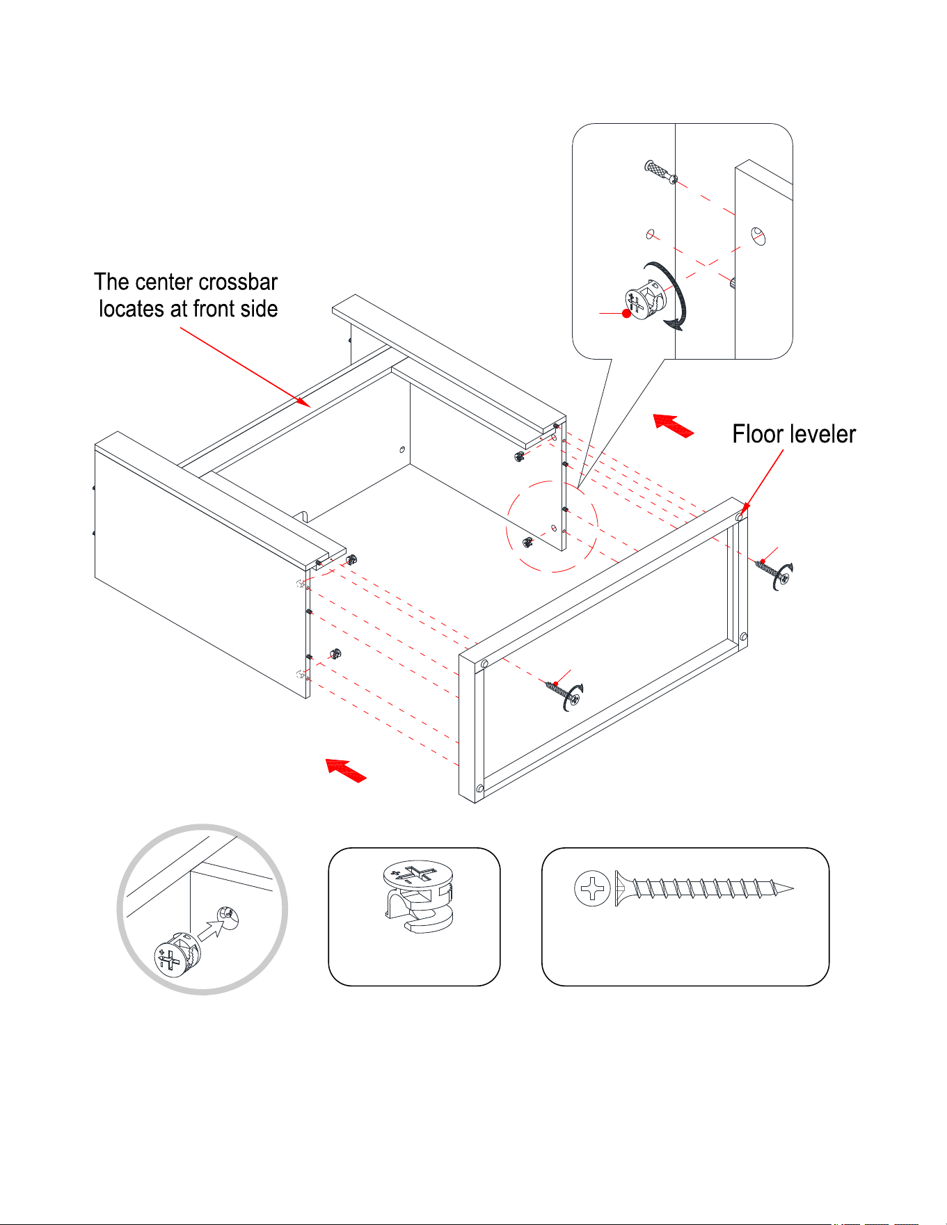
10. Align and attach the Media Shelf (B) between the Side Panels (D and E) by engaging four Cam Locks (1).
① x 4
D
E
B
B
D/E
1
14
Assembly Instructions
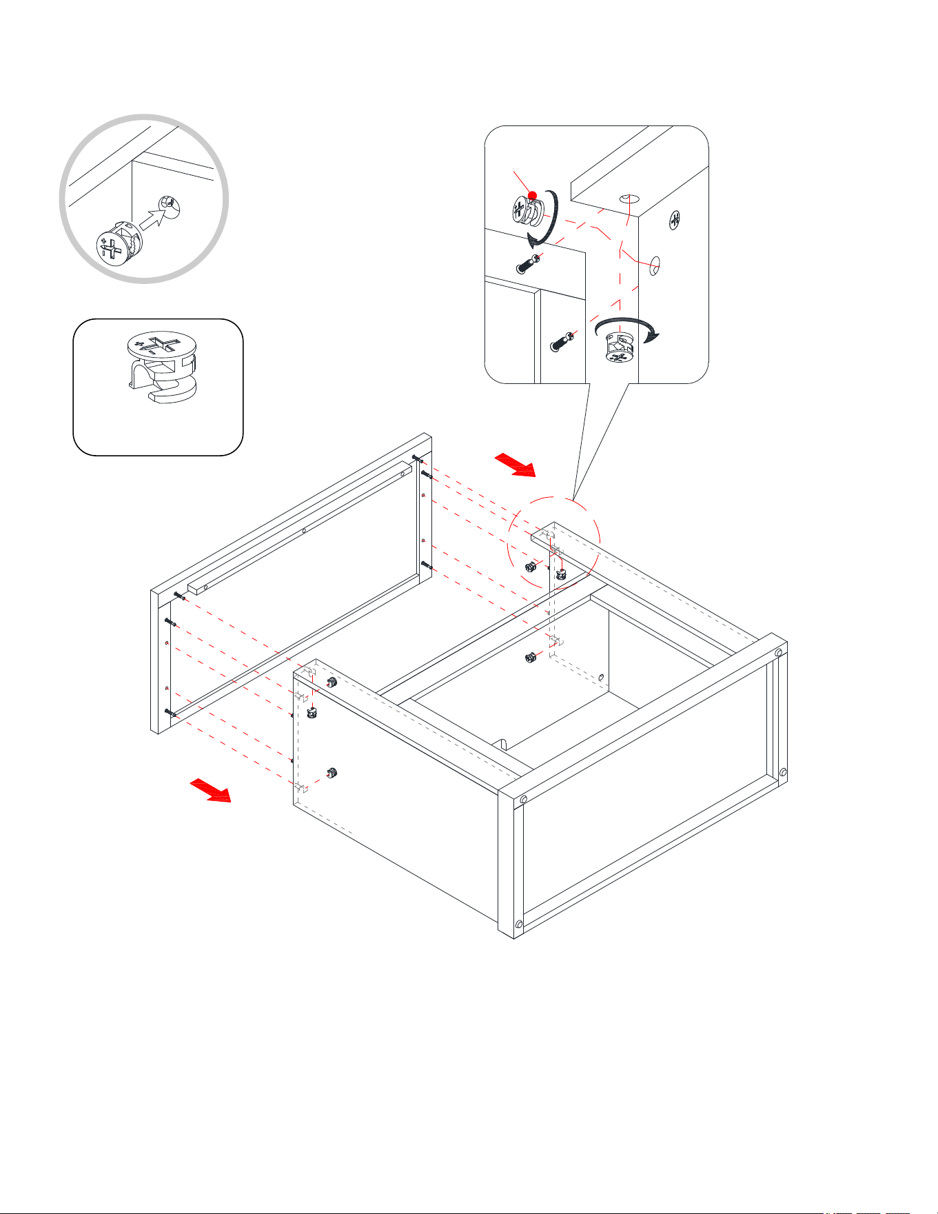
11. Using the wood dowels as a guide, firmly press the previous assembly to the Base (C) and fasten them into
place by engaging four Cam Locks (1).
12. Proceed to thread two 40 mm Screws (7) through the Base (C) and securely screw into the Front Moldings
(F and G).
D
E
C
F
G
1
C
D/E
7
7
① x 4
⑦ x 2
15
Assembly Instructions
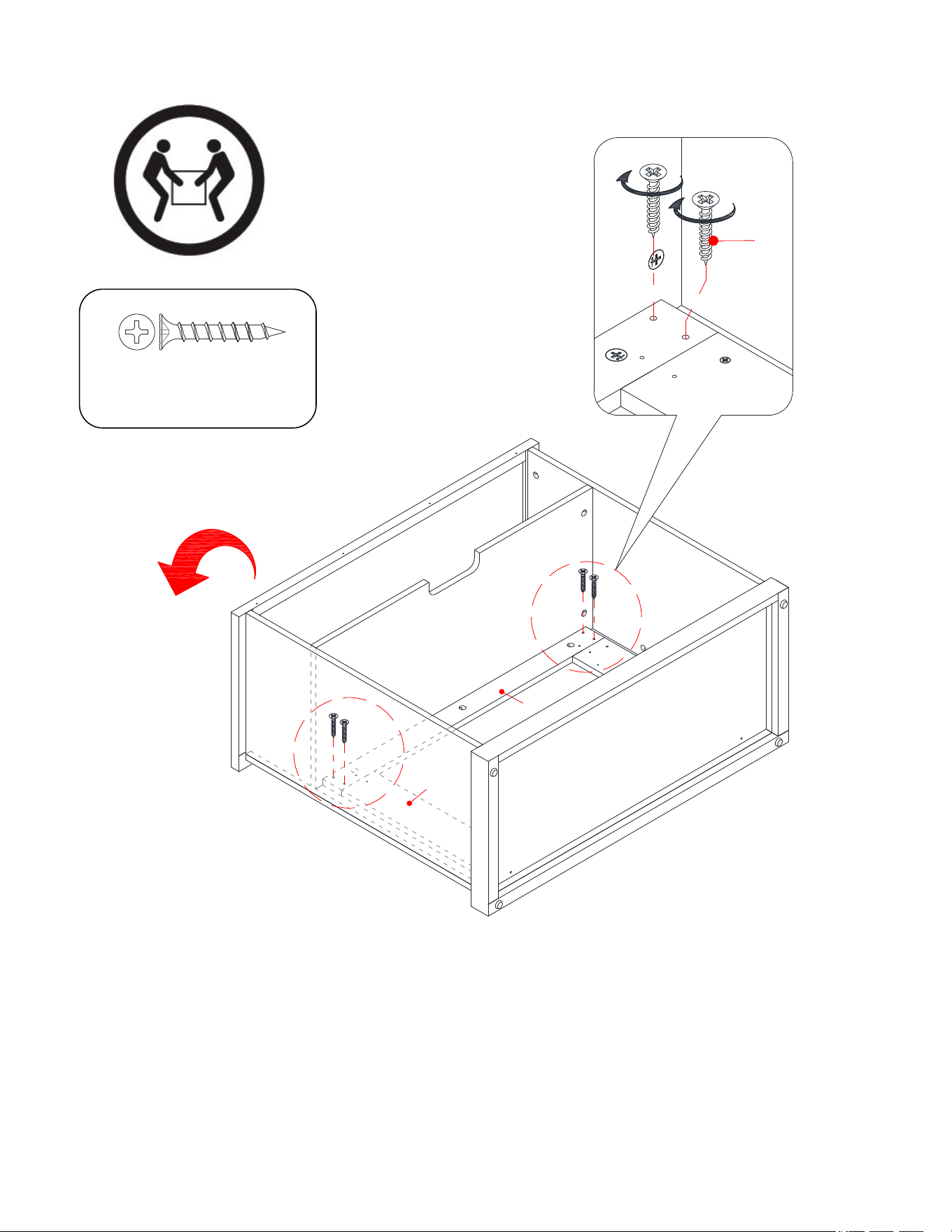
13. Place the Top Panel (A) onto the inserted wood dowels on the vertical panels (D, E, F and G) and fasten it
in place by engaging six Cam Locks (1).
① x 6
D
E
A
F
G
1
D/E
F/G
A
16
Assembly Instructions
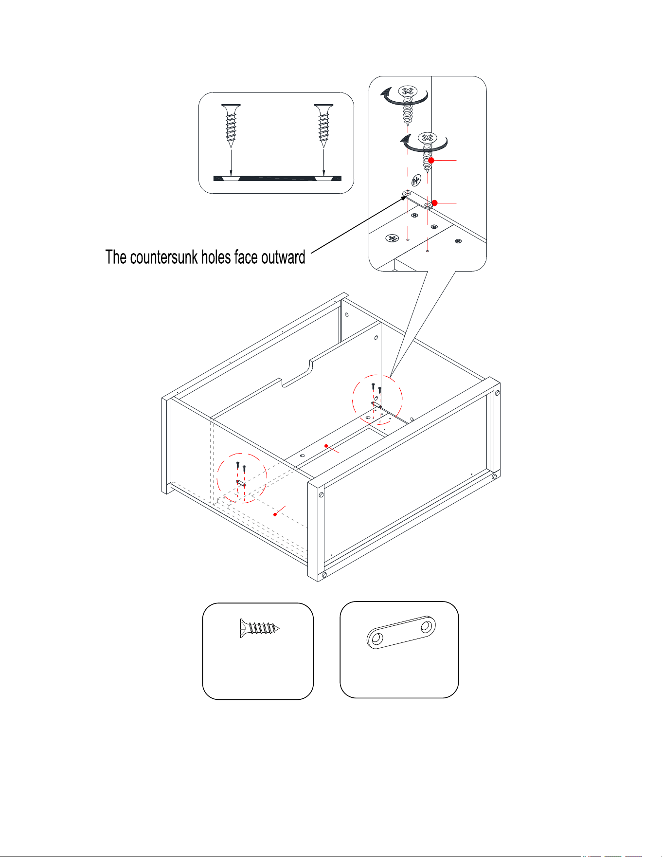
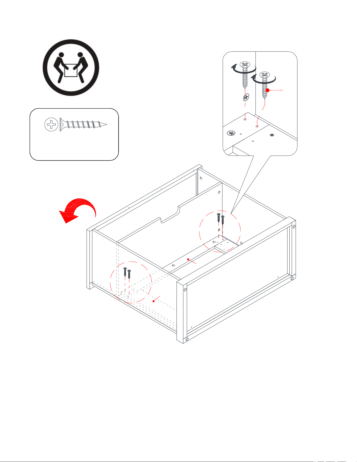
14. Ask for assistance to flip the unit around at its front edge as shown.
15. Fasten the Center Crossbar (I) to the Front Moldings (F and G) with four 28 mm Screws (6).
I
6
I
F
G
F/G
⑥ x 4
17
Assembly Instructions
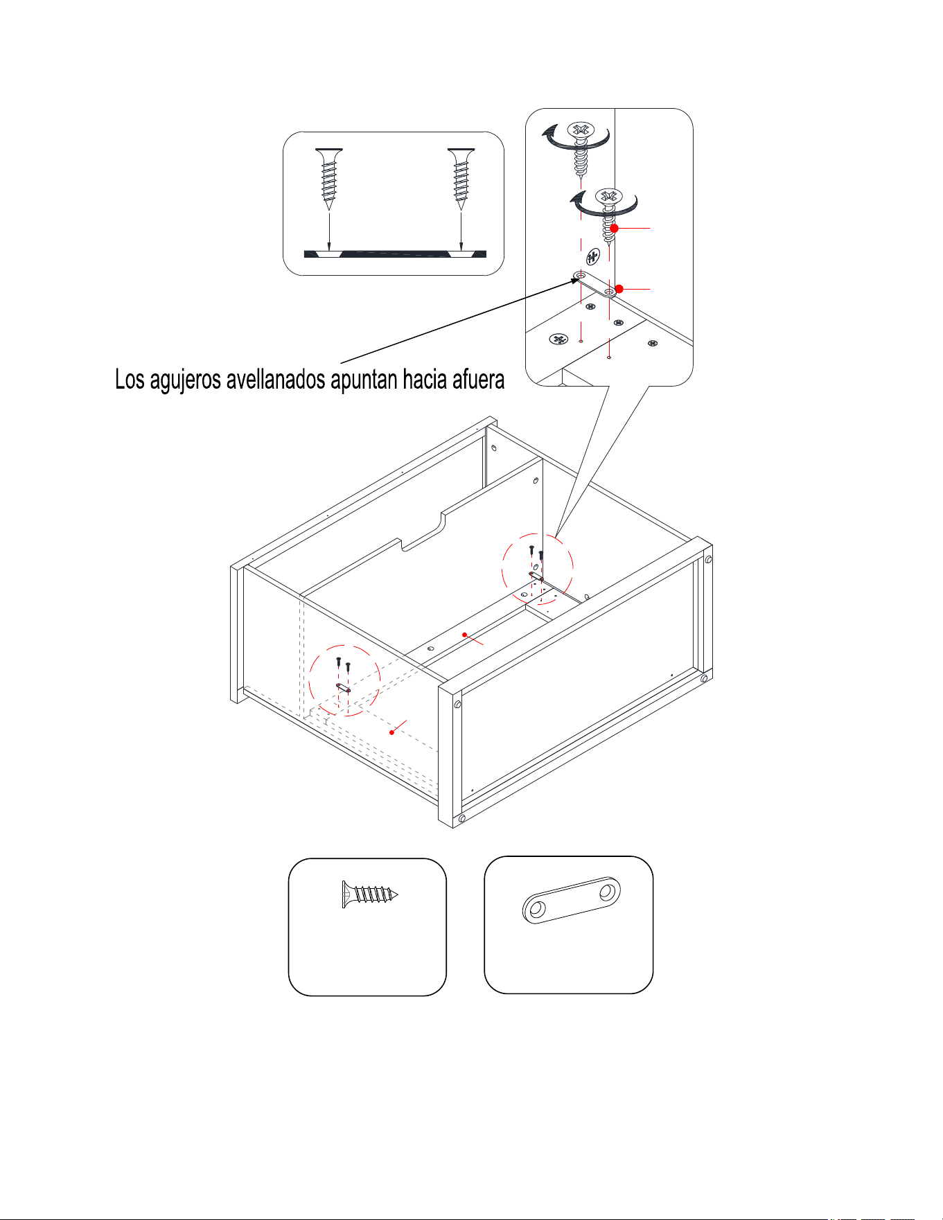
16. With the pilot holes as a guide, fasten the Center Crossbar (I) to the stiles on Front Moldings (F and G) by
attaching two Mending Plates (8) at the joints, using two 12 mm Screws (4) per plate.
④ x 4
⑧ x 2
I
F
G
F/G
I
4
8
18
Assembly Instructions
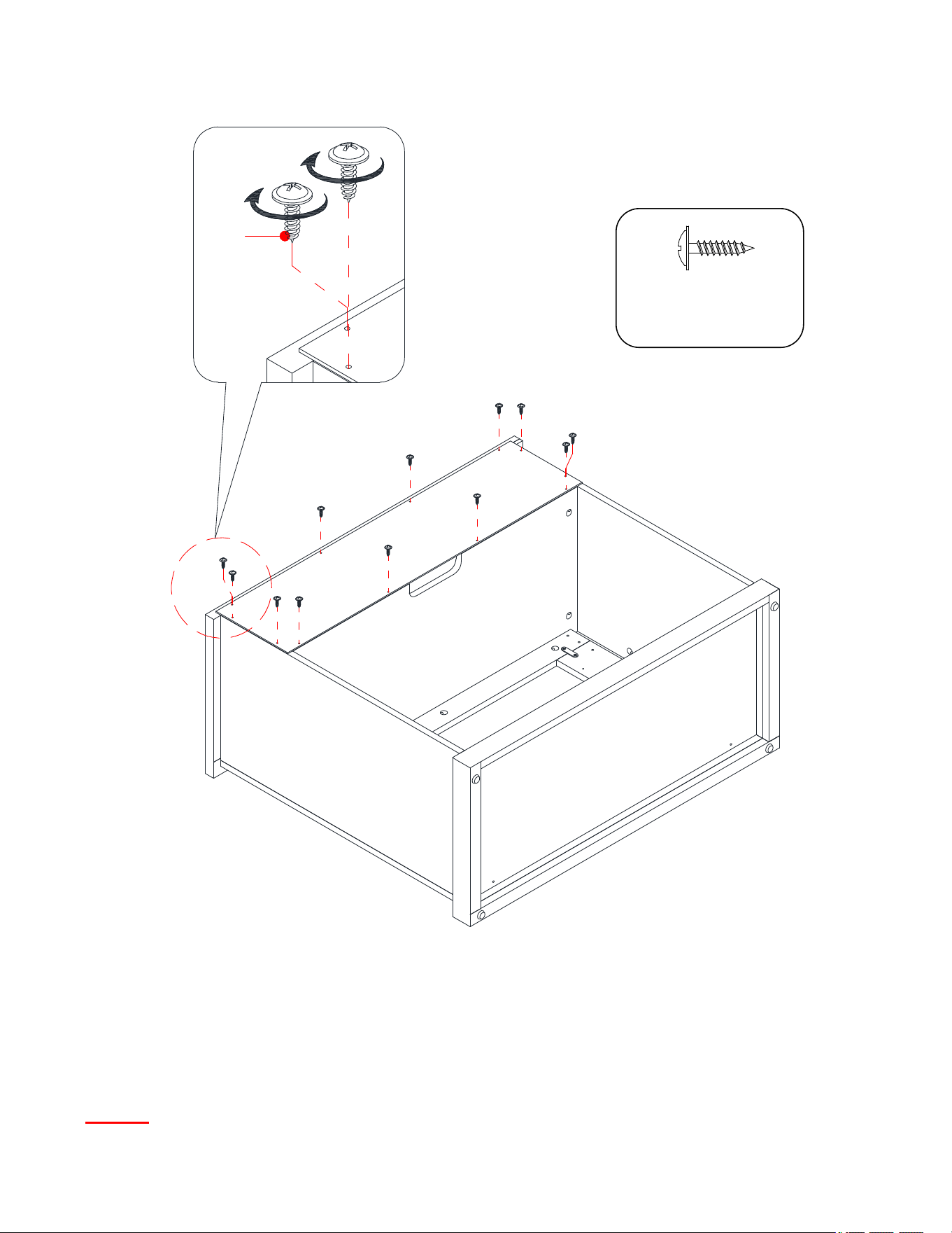
17. Now, go back and securely tighten all the Cam Locks and the Screws. Make sure that all the parts are tight
and there are no gaps between the parts. This will help keep the unit square.
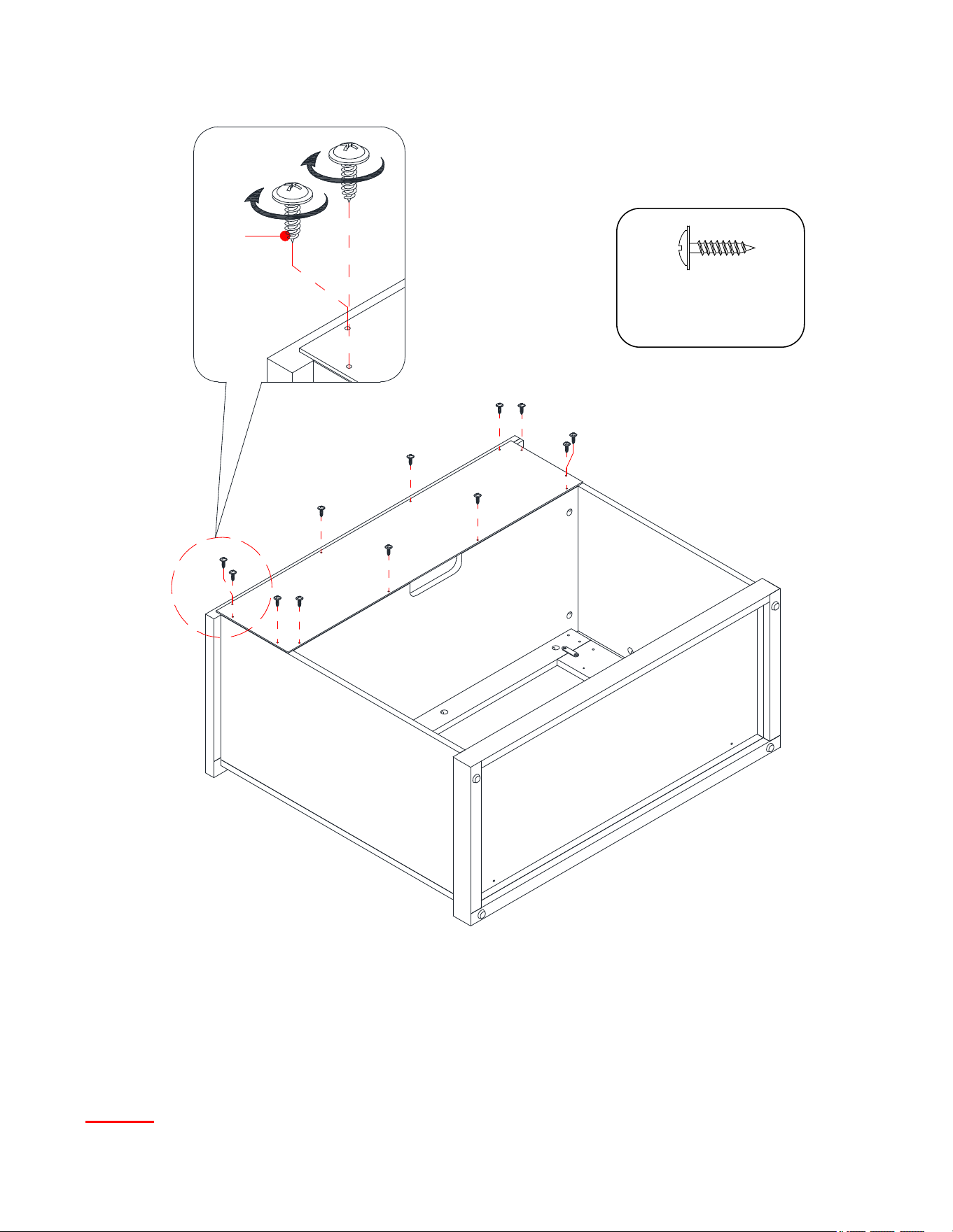
18. Pick up the Back Panel (J) and align the pre-drilled holes against the upper long edge with the pilot holes on
the back of Top Panel (A). Attach the Back Panel (J) in place using the provided 15 mm Washer Head
Screws (5).
NOTE: We recommend attaching back panel with washer head screws at the corners first.
⑤ x 12
J
5
19
Assembly Instructions
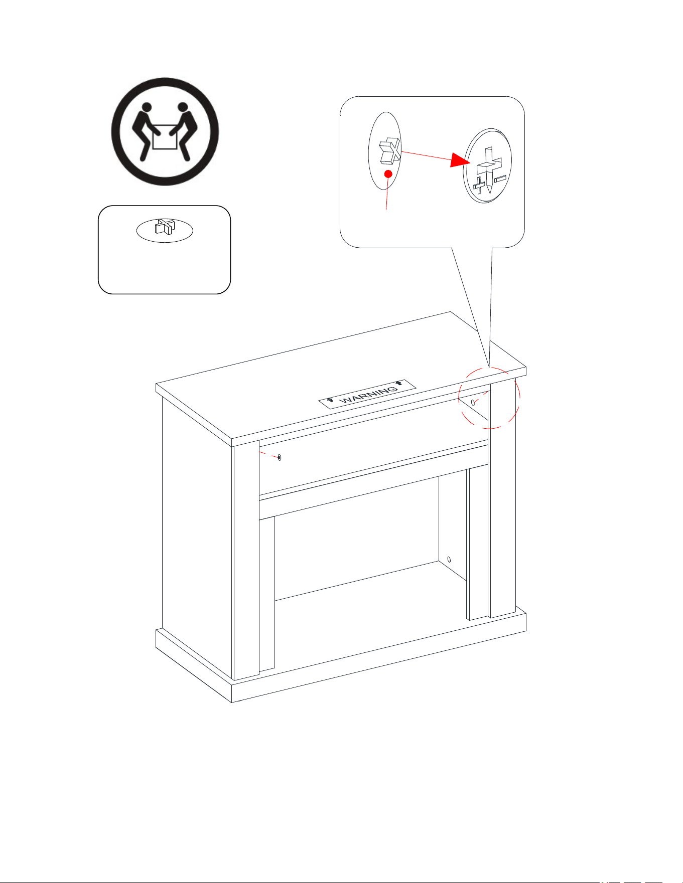
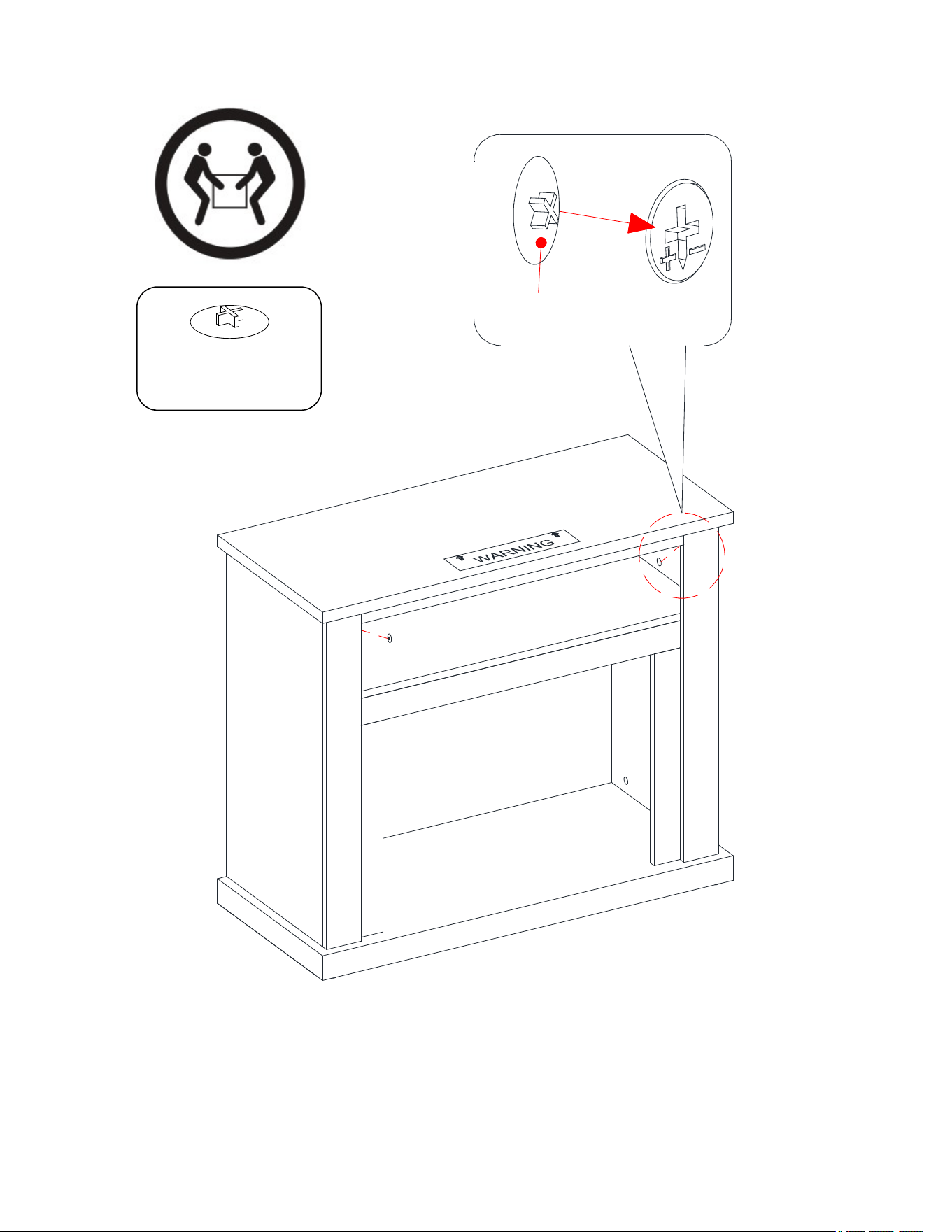
19. Ask for assistance to stand the unit upright.
20. Plug the Cam Lock Covers (9) onto the visible Cams Locks to conceal the Cams.
⑨ x 6
D
E
9
20
Assembly Instructions
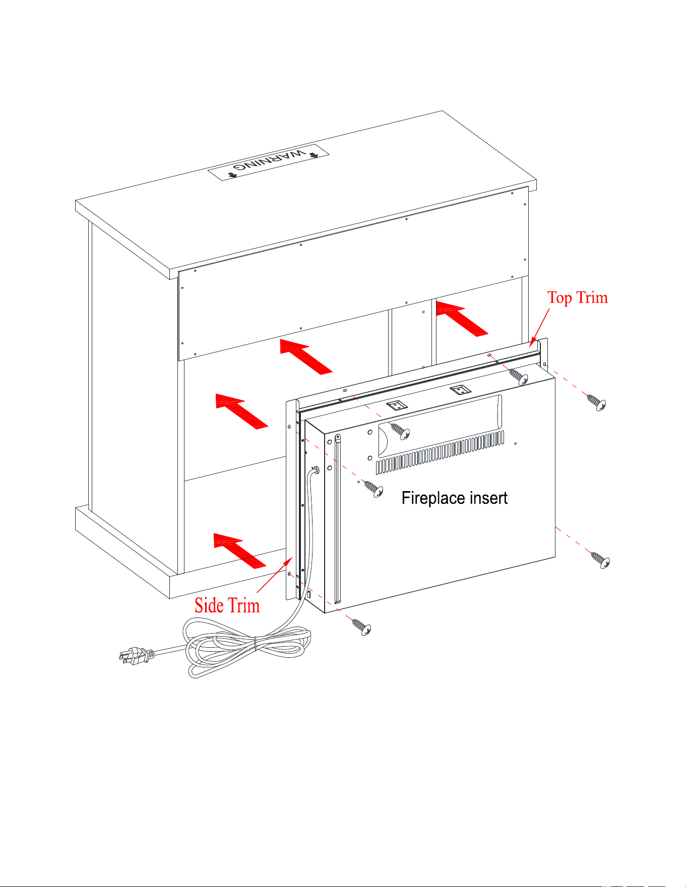
21. Unpack the fireplace insert from the inner box and follow the instructions to install the Top Trim and Side
Trims to the fireplace insert.
22. Lift the fireplace insert carefully into the back of the assembled mantel and center it in the opening.
DO
NOT drag the insert across the Base (C) as it may scratch the unit.
C
F
21
Assembly Instructions
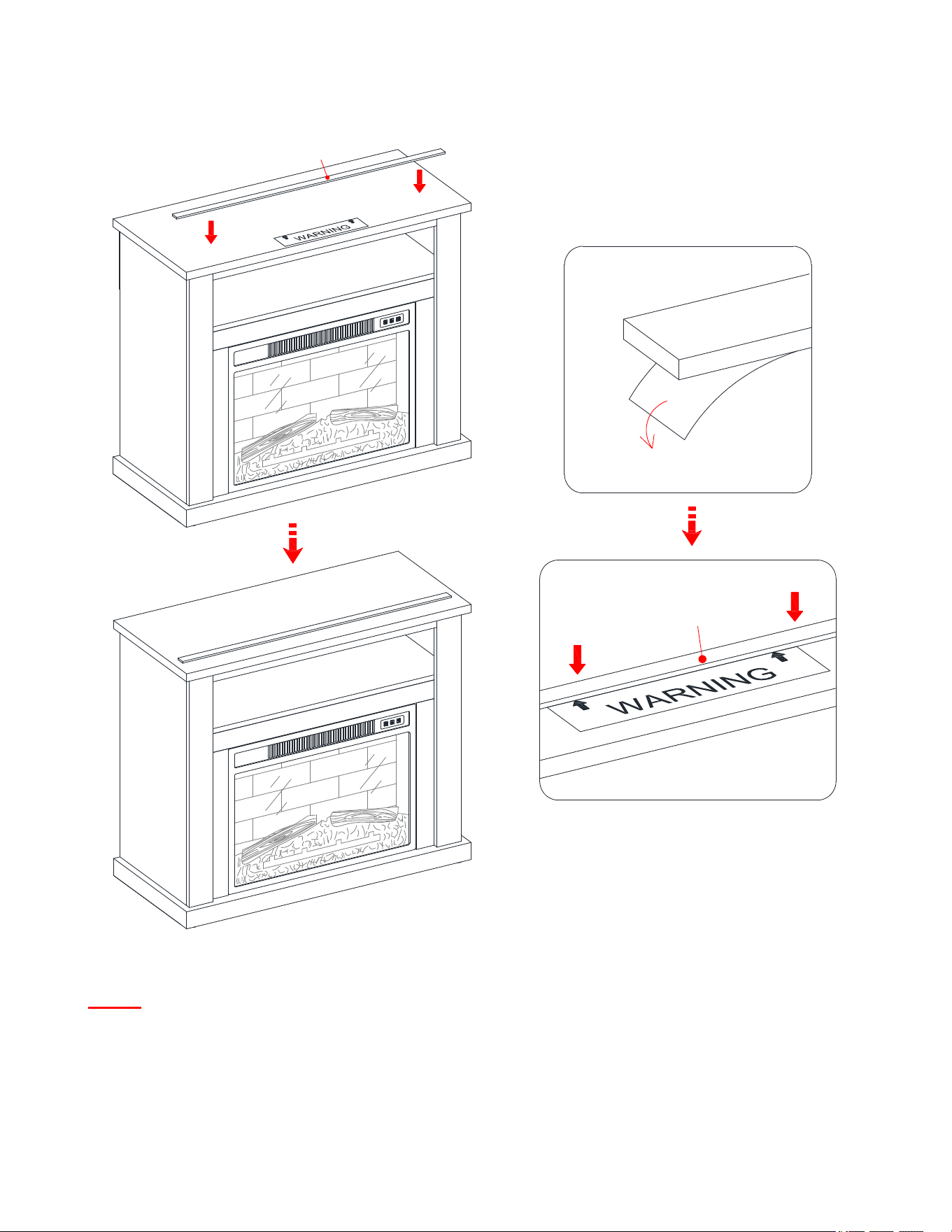
NOTE: To prevent your TV from tipping, you must install the Strip Stopper if you place your flat panel
television directly on the console. Otherwise, skip to step 24.
23. Remove the paper backing from the Stop Rail (K), then properly align the Stop Rail with the top edge of the
stopper template on Top Panel (A). Press down on the Stop Rail to help adhesion.
24. Carefully remove the stopper template from the Top Panel (A).
K
K
A
K
A
22
Assembly Instructions
Tools required (not provided): Phillips screwdriver, stud finder, tape measure, pencil, power drill and 1/8’’ drill bit.
25. Ask for assistance to position the assembled fireplace at the desired location against a wall. If necessary,
adjust the pre-attached floor levelers at the bottom of the Base (C) to level the unit.
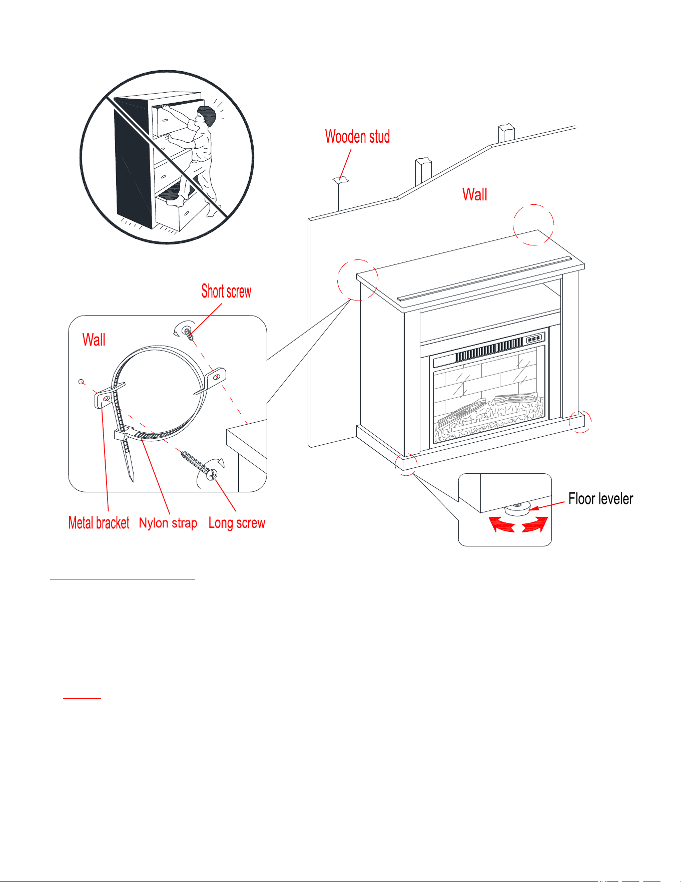
26. Now, follow the instructions printed on the plastic bag containing the Tipping Restraint Hardware to attach
the tip-over restraints to the unit and the wall.
NOTE: The tipping restraint hardware included is for wooden stud wall construction. It must be attached
to a wall stud. Depending upon your wall construction, different anchor hardware maybe required. Please
contact your local hardware store for assistance. Young children can be seriously injured by tipping
furniture. You must install the tipping restraint hardware with the unit to prevent the unit from tipping,
causing any accidents or damage. The tipping restraints are intended only as a deterrent, they are not a
substitute for proper adult supervision. The tipping restraints are not earthquake restraints. If you wish to
add the extra security of earthquake restraints, they must be purchased and installed separately.
27. Connect the fireplace to a power transformer. Follow the separated operating manual of electric fireplace to
control your fireplace.

23
Care and Maintenance
Use a soft, clean cloth that will not scratch the surface when dusting.
Use of furniture polish is not necessary. Should you choose to use polish, test first in an inconspicuous area.
Using solvents of any kind on your furniture may damage your furniture’s finish.
Never use water to clean your furniture as it may cause damage to the finish.
Always use coasters under beverage glasses and flowerpots.
Liquid spills should be removed immediately. Using a soft, clean cloth, blot the spill gently. Avoid rubbing.
Always use protective pads under hot dishes and plates. Heat can cause chemical changes that may create
spotting within the furniture finish.
In the event that your furniture is stained or otherwise damaged during use, we recommend that you call a
professional to repair your furniture.
Check bolts/screws periodically and tighten them if necessary.
Further Advice about Wood Furniture Care
It is best to keep your furniture in a climate-controlled environment. Extreme temperature and humidity
changes can cause fading, warping, shrinking and splitting of wood. It is advised to keep furniture away from
direct sunlight as sun may damage the finish.
Proper care and cleaning at home will extend the life of your purchase. Following these important and helpful
tips will enhance your furniture as it ages.
Cleaning Trim for Fireplace
Clean the metal trim using a soft cloth, slightly dampened with citrus oil based product and buff with a clean
soft cloth. DO NOT use brass polish or household cleaners as these products will damage the metal trim. Citrus
oil based products can be obtained at supermarkets or hardware stores.
A touch-up pen has been provided to minimize the small nicks or scratches that may occur during assembly or
shipping.
We hope you enjoy your purchase for many years.
Thank you for your purchase!
QUALITY GUARANTEE
We are confident that you will be delighted with your Whalen Furniture purchase.
Should this product be defective in workmanship or materials or fail under normal use, we will repair or replace
it for up to one (1) year from date of purchase. Every Whalen Furniture product is designed to meet your
highest expectations. We guarantee that you will immediately see the value of our fine furniture.
This warranty gives you specific legal rights and you may also have other rights which vary from State to State.
Whalen Furniture Manufacturing
1578 Air Wing Road
San Diego CA, 92154, USA
Customer Service: 866-942-5362
8:30 a.m. - 4:30 p.m., PST, Monday to Friday
www.whalenstyle.com

ESTE INSTRUCTIVO CONTIENE INFORMACION IMPORTANTE DE SEGURIDAD.
POR FAVOR LEA Y MANTENGA PARA USO FUTURO.
Fecha 2020-07-16 Rev. 0001-A
Consola para medios con chimenea
Modelo # MSD036158813001 Acabado Negro
# MSD036158813002 Acabado Cereza oscuro
ENSAMBLE REQUERIDO POR ADULTO
Si tienen alguna pregunta acerca del ensamble o si alguna parte está faltante, no retorne esté producto
a la tienda donde lo compro. Por favor llame a nuestro departamento de ayuda al cliente teniendo su
instructivo y lista de partes para proveer el modelo, nombre de parte o el número de fábrica:
866-942-5362
Hora estándar del Pacífico: 8:30 a.m. - 4:30 p.m., de Lunes a Viernes
O visite nuestra página de Internet 24 horas al día, 7 días a la semana para asistencia
www.whalenstyle.com
O mande un correo electrónico a parts@whalenfurniture.com
LOTE NÚMERO:
FECHA DE COMPRA: / /
2
FABRICANTE: Whalen Furniture Manufacturing
CATALOGO : Consola para medios con chimenea
MODELO # MSD036158813001 / MSD036158813002
M Á X IMO
P E SO R E C O M EN DA DO
POSICIONE LA TELEVISIÓN ATRÁS DEL TOPE
PARA MAYORÍA DE LAS TELEVISIONES
DE PANTALLA PLANA DE 42”
CARGA MÁXIMA 50 lb. (22.7 kg)
CARGA MÁXIMA 50 lb. (22.7 kg)
ESTA UNIDAD NO DEBE UTILIZARSE CON TELEVISIONES CRT O DE TUBO.
UTILIZARSE ÚNICAMENTE CON TELEVISIONES DE PANTALLA PLANA Y EQUIPO DE AUDIO/VIDEO
QUE TENGA LA MEDIDA/PESO RECOMENDADO. NUNCA UTILIZAR CON TELEVISIONES MÁS
GRANDES/PESADAS DE LAS RECOMENDADAS. PARA EVITAR INESTABILIDAD COLÓQUELA EN EL
CENTRO DE LA UNIDAD; LA BASE DE LA TELEVISIÓN DEBE DE REPOSAR SOBRE LA SUPERFICIE
DE SOPORTE DE LA UNIDAD SIN REBASAR LAS ORILLAS. LAS TELEVISIONES DE PANTALLA
PLANA COLOCADAS INAPROPIADAMENTE, O LAS TELEVISIONES DE PANTALLA PLANA
INCLUYENDO EQUIPO QUE SOBREPASA LAS MEDIDAS Y PESOS RECOMENDADOS PUEDEN
CAERSE Y/O ROMPER LA UNIDAD, CAUSANDO POSIBLES DAÑOS O LESIONES. PARA USO DE
TELEVISIONES DE HASTA 50 LBS (22.7 KG) O MENOS. USO CON TELEVISIONES DE MAYOR PESO
PUEDE RESULTAR EN INESTABILIDAD CAUSANDO QUE LA UNIDAD CAIGA EN ALGUNOS CASOS
PROVO
CAR DAÑOS O MUERTE.
Niños han muerto a cause de muebles que se voltean.
Para reducir el riesgo de que se voltee un mueble:
SIEMPRE instalar la restricción de inclinación provista.
PARA uso de televisiones que pesan 50 lbs. o menos. El uso de televisiones más
pesadas puede resultar en instabilidad causando una volcadura resultando en muerte o
lesiones graves.
NUNCA permitir que niños se paren, se trepan, o se cuelguen de los cajones,
puertas, o repisas.
NUNCA abrir más de un cajón a la vez.
Poner los objetos más pesados en los cajones inferiores.
El uso de restricciones de inclinación solo reduce, pero no elimina, el riesgo de
vol
cadura
.
ADVERTENCIA
3
IMPORTANTE
Antes de comenzar:
Abra, identifique y cuente todas las partes antes del ensamble. Coloque las piezas sobre
una superficie plana y no abrasiva. Tendrá que las partes identificadas en la página 4 y 5 de este manual de
instrucciones.
NOTA: ES MUY IMPORTANTE PARA EL USO DE PEGAMENTO CON LOS PERNSO DE MADERA.
EL. EXCESO DE PEGAMENTO SE PUEDE LIMPIAR CON UN PAÑO HÚMEDO.
Inserte el perno por lo menos a la mitad del camino golpeando ligeramente con un mazo de pegamento, SI ES
NECESARIO.
SISTEMA DE OPERACIÓN DE TUERCA DE FIJACIÓN
CÓMO FUNCIONA LA INSTALACIÓN DE MONTAJE (KD)
1. Fijar los tornillos de fijación en los orificios pequeños. Conectar ambos paneles, cerciorandose que los
tornillos de fijación entren bien y que estos queden en los orificios al final del panel con tuercas de fijación.
2. Inserte las tuercas de fijación en los orificios grandes del panel. Hacer que la flecha en la tuerca este
apuntando hacia la entrada del tornillo de fijación.
3. Una vez que el tornillo este conectado dentro, tome un destornillador de cruz y apriete la tuerca en
dirección de las manecillas del reloj.
4. Coloque la tapa de la tuerca de fijación sobre la misma en la ranura de cruz, ver detalle.
Está listo para el ensamble KD de esta unidad.
X
X
1
2
3
4
4
Lista de partes y material de ferretería
Por favor lea completamente las instrucciones y verifique que estén todas las partes antes de iniciar el
ensamblado.
A- Panel superior (Cant. 1) B- Repisa media (Cant.1) C- Base (Cant. 1)
D- Panel izquierdo (Cant. 1) E- Panel derecho (Cant. 1) F- Moldura izquierda frontal (Cant. 1)
G- Moldura derecha frontal (Cant. 1) H- Moldura superior frontal (Cant.1) I- Soporte central (Cant.1)
J- Panel posterior (Cant. 1) K- Riel tope (Cant. 1)
Inserto de chimenea (Cant. 1) Control remoto con batería (Cant. 1)
5
Lista de partes y material de ferretería
Por favor lea completamente las instrucciones y verifique que estén todas las partes antes de iniciar el
ensamblado.
(1) Tuerca de fijación (2) Perno de fijación (3) Clavija de madera de M8 x 30 mm
(Cant. 23+1 extra) (Cant. 23+1 extra) (Cant. 22+1 extra)
(4) Perno de M3.5 x 12 mm (5) Perno de cabeza de arandela de M3.5 x 15 mm (6) Perno de M4 x 28 mm
(Cant. 4+1 extra) (Cant. 12+1 extra) (Cant. 4+1 extra)
(7) Perno de M4 x 40 mm (8) Placa de unión (9) Tapa de la tuerca de fijación
(Cant. 5+1 extra) (Cant. 2) (Cant. 6+1 extra)
Pegamento (Cant. 1) Plumón (Cant. 1) Juego de restricción de movimiento (Cant. 2)
(Incluido en bolsa de plástico)
Herramientas requeridas (no incluidas): Desarmador estrella, localizador de barrotes, cinta métrica, lápiz,
taladro y broca de 1/8”.
6
Instrucciones de ensamble
1. Desempacar la unidad y confirmar que se tiene todo el material de ferretería y partes requeridas. Ensamblar
la unidad en un piso alfombrado o en el cartón vacío para evitar rasguños.
2. Atornillar los pernos de fijación (2) en los agujeros pequeños designados en el panel superior (A), en la
repisa media (B) y en la base (C) con el desarmador estrella. NO sobre apretar los pernos de fijación.
② x 13
2
A
B
C
7
Instrucciones de ensamble
3. Atornillar los pernos de fijación (2) en los agujeros pequeños designados en los paneles laterales (D y E) y
en las molduras frontales (F y G).
2
D
E
G
F
② x 10
8
Instrucciones de ensamble
4. Insertar las clavijas de madera de 30 mm (3) en los agujeros internos en la repisa media (B), en la moldura
superior frontal (H) y en el soporte central (I). Usar una cantidad pequeña de pegamento en ambos lados de
las clavijas.
③ x 8
3
3
3
3
3
3
3
3
3
3
H
I
B
9
Instrucciones de ensamble
5. Alinear y adjuntar la moldura superior frontal (H) al frente del panel superior (A) con 3 pernos de 40 mm
(7).
⑦ x 3
7
H
A
10
Instrucciones de ensamble
6. Alinear y adjuntar el soporte central (I) a la repisa media (B) empleando 3 tuercas de fijación (1)
(Consulte la página 3 del sistema de tuerca de fijación).
① x 3
1
B
I
B
I
11
Instrucciones de ensamble
7. Insertar las clavijas de madera de 30 mm (3) en los agujeros internos de los paneles laterales (D y E) y de
las molduras frontales (F y G). Usar una cantidad pequeña de pegamento en ambos lados de las clavijas.
③ x 14
3
33
3
3
3
3
3
D
E
3
3
3
3
3
F
G
3
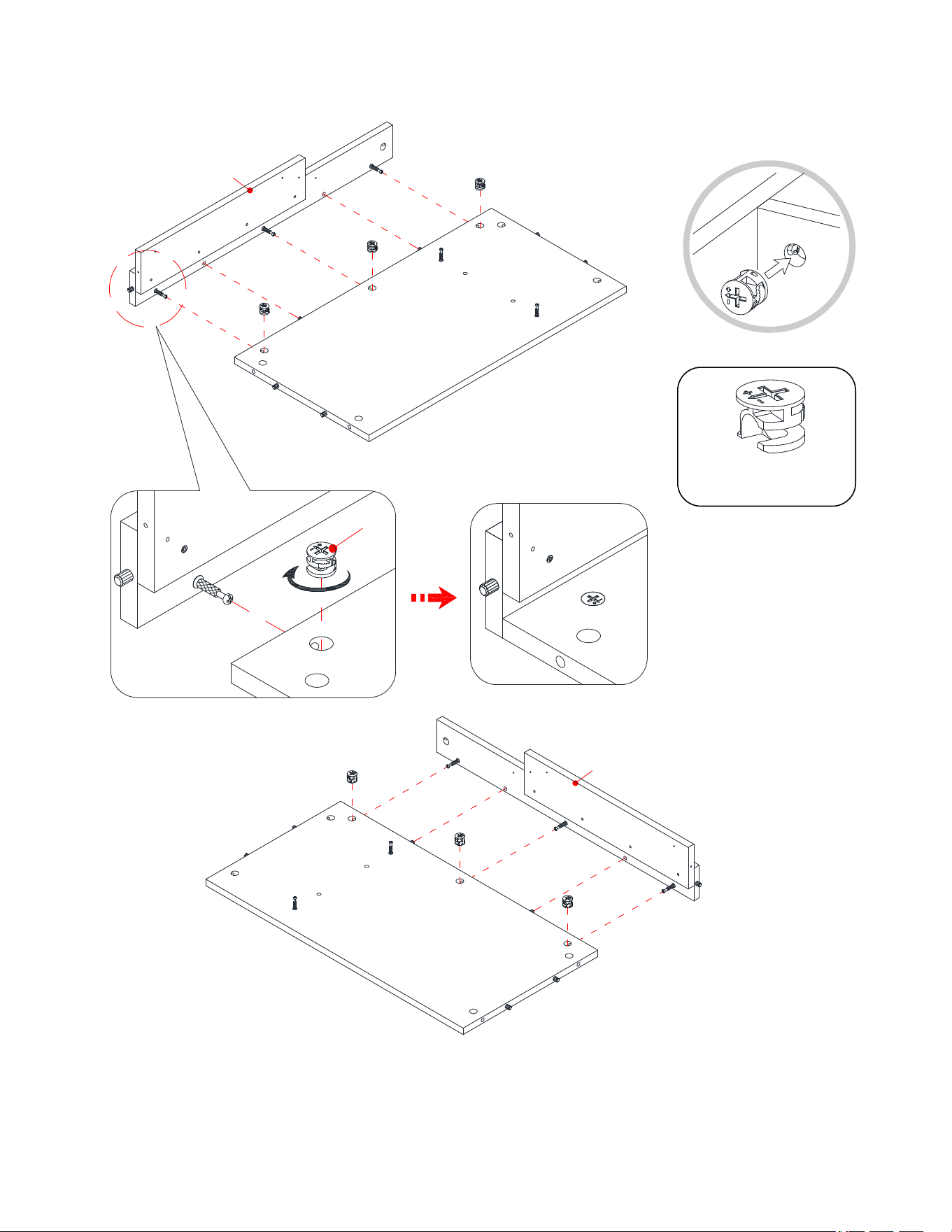
12
Instrucciones de ensamble
8. Alinear y adjuntar la moldura izquierda frontal (F) al panel izquierdo (D) empleando 3 tuercas de fijación
(1).
9. Repetir el mismo procedimiento para adjuntar la moldura derecha frontal (G) al panel derecho (E).
① x 6
1
D
E
F
G
F/G
D/E
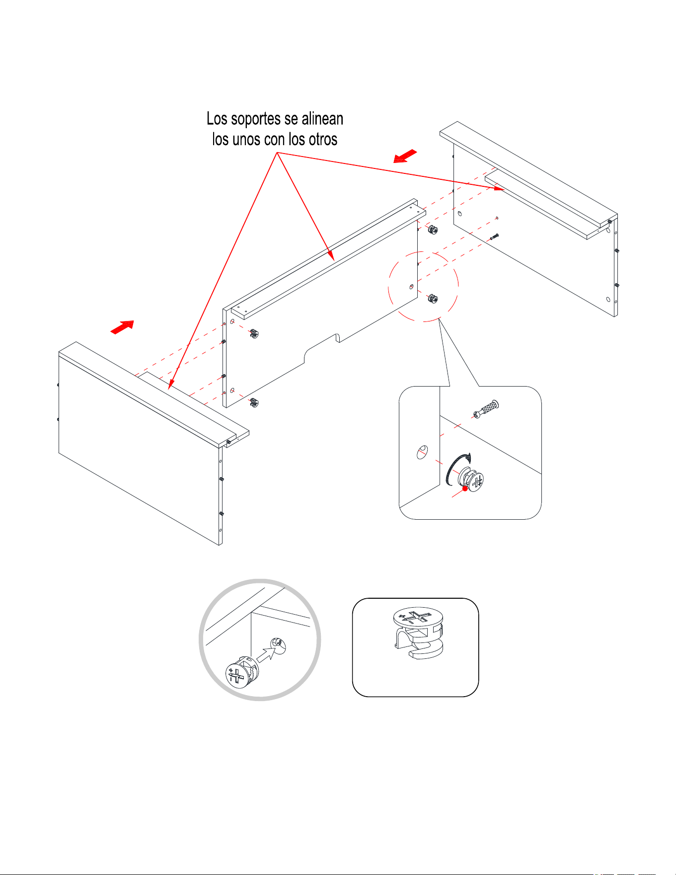
13
Instrucciones de ensamble
10. Alinear y adjuntar la repisa media (B) entre los paneles laterales (D y E) empleando 4 tuercas de fijación
(1).
① x 4
D
E
B
B
D/E
1
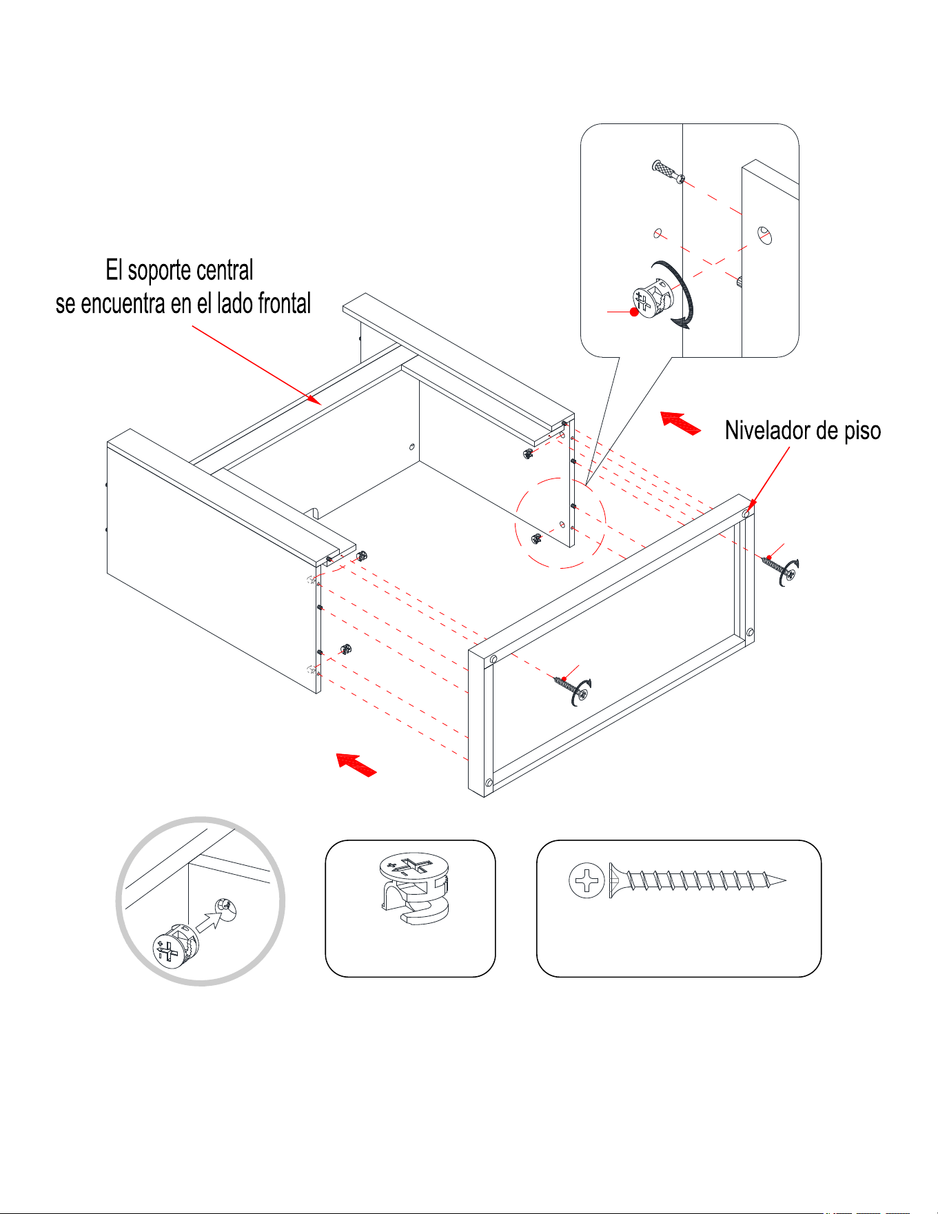
14
Instrucciones de ensamble
11. Usando las clavijas de madera como guía, presionar el ensable previo a la base (C) y sujetar en su lugar
empleando 4 tuercas de fijación (1).
12. Proceder a ensartar 2 pernos de 40 mm (7) a traves de la base (C) y atornillar en la molduras frontales (F y
G).
D
E
C
F
G
1
C
D/E
7
7
① x 4
⑦ x 2
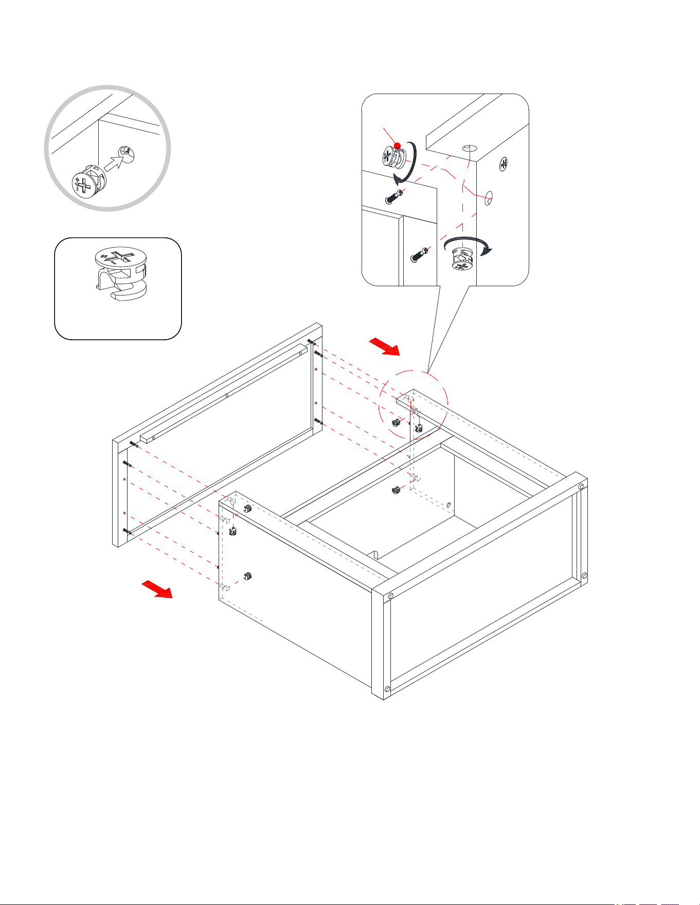
15
Instrucciones de ensamble
13. Poner el panel superior (A) en las clavijas de madera insertadas en los paneles verticales (D, E, F y G) y
sujetar en su lugar empleando 6 tuercas de fijación (1).
① x 6
D
E
A
F
G
1
D/E
F/G
A
16
Instrucciones de ensamble
14. Pedir asistencia para voltear la unida alrededor de su borde frontal como se muestra.
15. Sujetar el soporte central (I) a las molduras frontales (F y G) con 4 pernos de 28 mm (6).
I
6
I
F
G
F/G
⑥ x 4
17
Instrucciones de ensamble
16. Con los agujeros pilotos como guía, sujetar el soporte central (I) a los soportes en las molduras frontales (F
y G) adjuntando 2 placas de unión (8) en las conexiones, usando 2 pernos de 12 mm (4) por placa.
I
F
G
F/G
I
4
8
④ x 4
⑧ x 2
18
Instrucciones de ensamble
17. Ahora, volver y apretar todas las tuercas de fijación y los pernos, asegurar que todas las partes estén
apretadas y de que no hay huecos entre las partes, esto ayudara a mantener la unidad cuadrada.
18. Tomar el panel posterior (J) y alinear a los agujeros pre-perforados en contra del borde superior largo con
los agujeros pilotos en la parte posterior del panel superior (A). Adjuntar el panel posterior (J) en su lugar
usando los pernos de cabeza de arandela de 15 mm provistos (5).
NOTA: Recomendamos adjuntar el panel posterior con pernos de cabezas de arandela en las esquinas
primero.
⑤ x 12
J
5
19
Instrucciones de ensamble
19. Pedir asistencia para poner la unidad en posición vertical.
20. Enchufar la tapa de las tuercas de fijación (9) sobre las tuercas de fijación visibles para esconder.
⑨ x 6
D
E
9
20
Instrucciones de ensamble
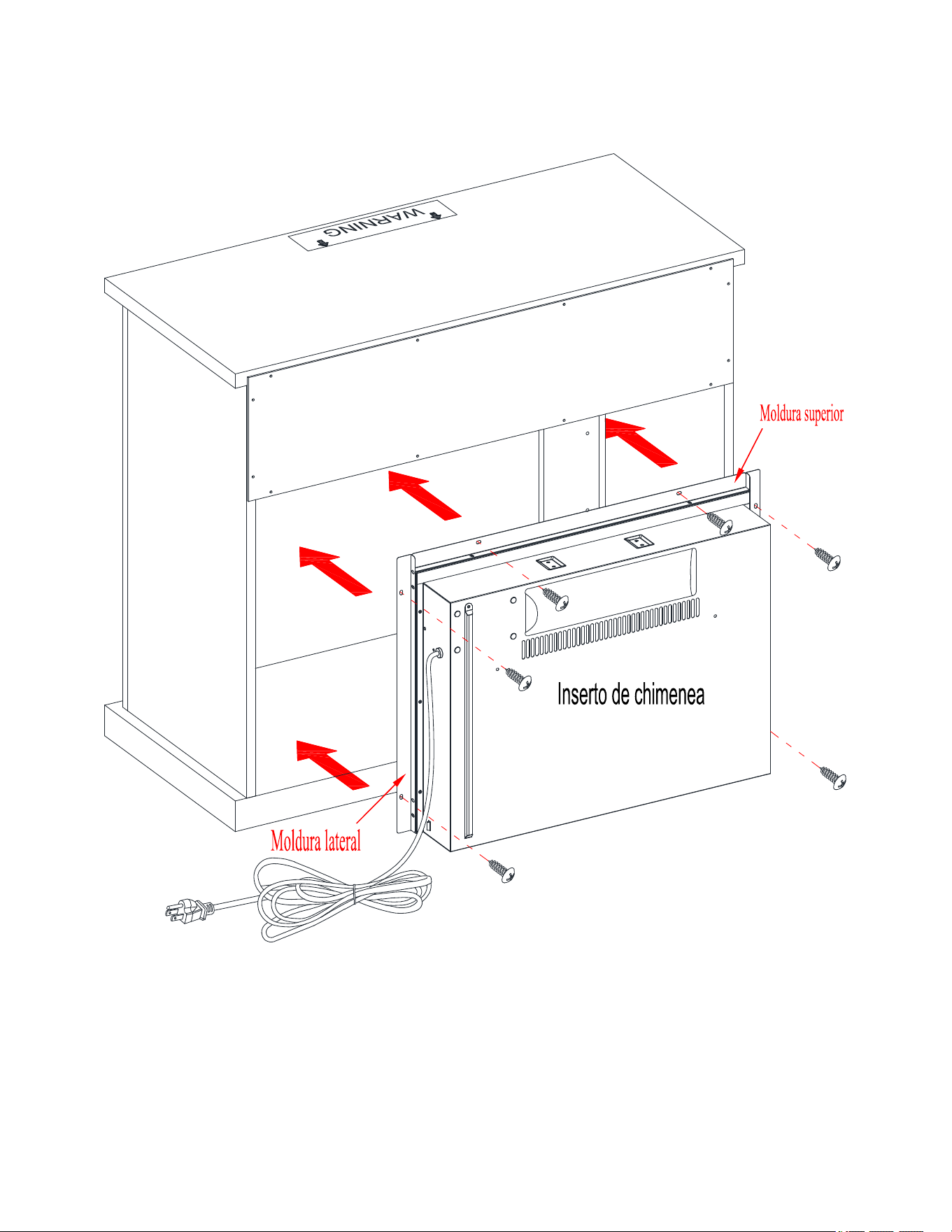
21. Desempacar el inserto de chimenea de la caja interior y seguir las instrucciones para instalar las molduras
superior y laterales al inserto de chimenea.
22. Poner con cuidado el inserto de chimenea en la parte posterior de la unidad y centrar en la abertura.
NO
arrastrar el inserto a través de la base (C) porque podría rayar la unidad.
C
F
21
Instrucciones de ensamble
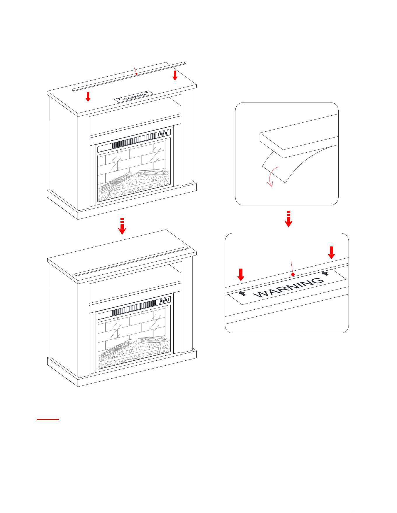
NOTE: Para prevenir la inclinación de su TV, debe instalar el riel tope si planea poner su televisión de
pantalla plana directamente sobre la consola. De otra manera, saltar al paso 24.
23. Retirar el respaldo de papel del riel tope (K), luego alinear el riel tope con el borde superior del templado
del tope en el panel superior (A). Presionar el riel tope para ayudar a la adhesion.
24. Retirar el templado del tope del panel superior (A).
K
K
A
K
A
22
Instrucciones de ensamble
Herramientas requeridas (no incluidas): Desarmador estrella, localizador de barrotes, cinta métrica, lápiz,
taladro y broca de 1/8”.
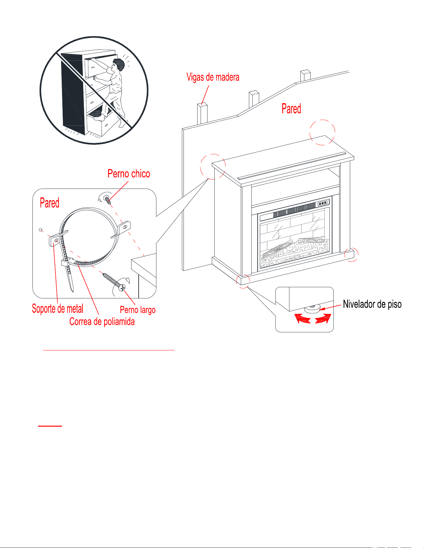
25. Pida asistencia para posicionar la chimenea ensamblada en el lugar deseado contra la pared. Si fuera
necesario, ajuste los niveladores de piso pre-adjuntados en la parte inferior de la base (C) para nivelar la
unidad.
26. Ahora, seguir las instrucciones impresas en la bolsa de plástico que contiene el juego de restricción de
movimiento para adjuntar los topes de movimiento a la unidad y a la pared.
NOTA: La ferretería de restricción de movimiento se incluye para la construcción de pared con vigas de
madera. Se debe sujetar a un barrote de pared. Dependiendo de la construcción de su pared, es posible que
se requiera ferretería diferente. Póngase en contacto con su ferretería local para obtener ayuda. Niños
pequeños pueden resultar lastimados por muebles inclinados. Debe instalar el juego de restricción de
movimiento con la unidad en función, para prevenir la inclinación de la unidad, causando cualquier
accidente o daño. El tope de movimiento es solo una protección, no hay substituto para la supervisión
adulta. El tope de movimiento no es contra terremoto. Si deseara añadir la seguridad adicional contra
terremotos, deben ser comprados e instalados por separado.
27. Conectar la chimenea a un transformador de poder. Seguir el manual de operación de la chimenea eléctrica
para controlar su chimenea.

23
Mantenimiento y Cuidados
Use una toalla suave y limpia para evitar daños y rayones.
Uso de cera para pulir muebles no es necesario. Si desea usar cera, pruebela en un área que no sea visible
para revisar su funcionamiento.
Usar solventes de cualquier tipo puede dañar el acabado del mueble.
Nunca use agua para limpiar la unidad, ya que le puede dañar el acabado.
Siempre utilice protección para vasos cuando los ponga sobre la unidad.
Líquidos derramados deben limpiarse inmediatamente, con una toalla suave evitando tallar.
Siempre utilizar protectores en caso de poner cosas calientes. El calor puede provocar una reacción química
en el acabado y dañarlo.
En caso que su unidad sea manchada durante el uso le recomendamos hablar a un profesional para que le ayude.
Revisar los pernos y tornillos periódicamente y apretarlos en caso que sea necesario.
Más recomendaciones para el cuidado de su mueble
Lo mejor es mantener la unidad en una área de clima controlado. Temperatura extrema y cambios de humedad
pueden causar cambios como partes pandas, molduras que se contraigan o que la madera se raje. Es
recommendable mantener la unidad lejos del sol directo ya que puede dañar el acabado.
Cuidados adecuados y limpieza pueden extender la vida útil de su unidad. Siga estas recomendaciones y
mantendra su mueble en buenas condiciones de uso por muchos años.
Limpiando el borde de la chimenea
Limpie el borde metálico usando un paño suave, lijeramente humedecido con productos hecho con aceite
cítrico y pulir con un paño suave y limpio. NO usar latón pulido u otros limpiadores caseros porque estos
productos dañaran el borde metálico. Productos hechos de aceite cítrico se pueden obtener en un supermercado
o en una tienda de material de ferretería.
Un plumón de retoque se ha proporcionado para minimizar los pequeños daños o rayones que pueden haber
ocurrido durante el montaje o el envío.
Esperamos que disfrute su mueble por muchos años.
¡Gracias por su compra!
GARANTÍA DE CALIDAD
Nosotros estamos seguros que usted se encontrará feliz con la compra de esté producto de Whalen Furniture.
Si esté producto tiene algun defecto de ensamble o material, o si tiene alguna falla en uso normal, nosotros lo
repararemos o lo re-emplazaremos hasta por un año a partir de la fecha de compra. Todo producto de Whalen
Furniture es diseñado para alcanzar sus espectativas más altas. Nosotros le garantizamos que inmediatamente
podrá ver el valor de nuestra mercancia de la más alta calidad.
Está garantia le proporciona derechos legales especificos y talvez tenga otros derechos que varian de estado a
estado.
Whalen Furniture Manufacturing
1578 Air Wing Road
San Diego CA, 92154, USA
Servicio al cliente: 866-942-5362
Hora estándar del Pacífico: 8:30 a.m. - 4:30 p.m., de Lunes a Viernes
www.whalenstyle.com