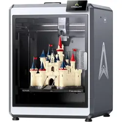
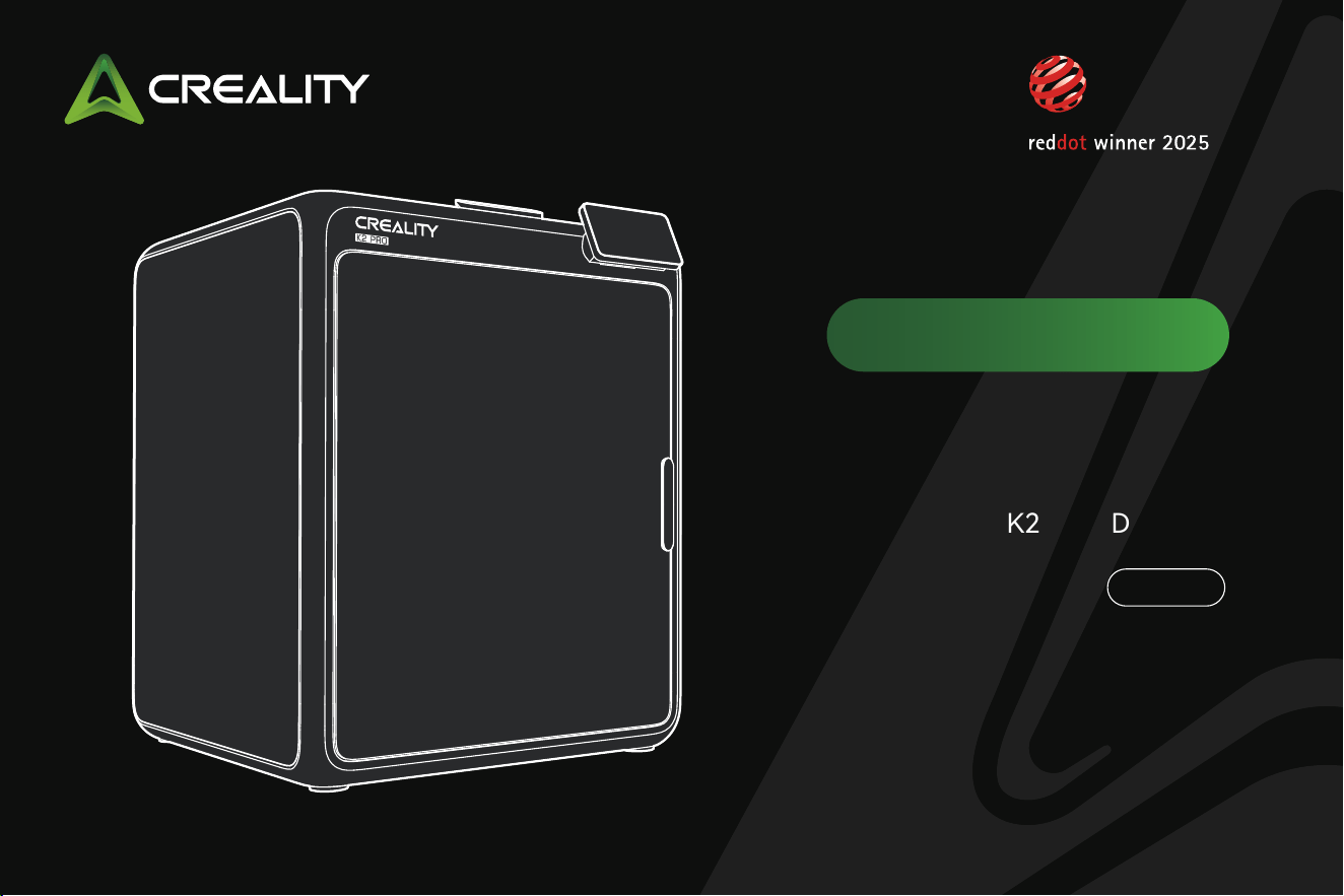
K2 Pro 3D Printer
K2 Pro
V 1.0_EN
User Manual
Thank you for choosing Creality products. This quick guide introduces the steps for unboxing, installation, and debugging. Please read it carefully before use.
For more detailed instructions, unboxing videos, and after-sales seice tutorials, please visit the Creality Wiki platform.
The Creality team is always ready to provide you with quality seice. If you encounter any problems during use, please contact us through the phone number
and email provided at the end of this quick guide.
Dear
Users
Bought a product but don't
know how to use it?
Don't wor, all your
confusions will be resolved!
Creality ocial Wiki
Comprehensive understanding of the new product,
immersive exploration of its features.
Detailed operation guides to help you get staed
eolessly.
Professional after-sales suppo platform oering
ecient solutions.
https://wiki.creality.com
Creality Cloud App
Creality Cloud – Your 3D
Printing Universe Awaits!
Discover the all-in-one 3D
printing platform designed
for all enthusiasts.
https://www.crealitycloud.com
Access a vast libra of high-quality models.
Built-in cloud slicing and Print Settings make printing
easier than ever.
Control remotely and print with just one click, anytime,
anywhere.
1. Do not use the printer in any way other than described herein in order to avoid personal inju or propey damage;
2. Do not place the printer near any heat source or ammable or explosive objects. We suggest placing it in a well-ventilated, cool and
dustless environment;
3. Do not expose the printer to a violent vibration or any other unstable environment, as this may cause poor print quality;
4. Please use recommended laments to avoid clogging of the extrusion head and causing damage to the machine;
5. Do not use the power cable of other products during installation. Always use a grounded three-prong power outlet, which accompa-
nies the printer;
6. Do not touch the nozzle and the heated bed during operation to avoid burns or personal inju;
7. Do not wear gloves or wraps while operating the machine to prevent entrapment of movable pas that could cause crushing and
cutting injuries to bodily pas;
8. Use the provided tools to clean the lament from the extruder in time taking advantage of the residual temperature after printing. Do
not touch the extruder directly when cleaning, otherwise it may cause burns;
9. Clean the printer frequently. Clean the printer body with a d cloth regularly after powering o the printer, wipe away dust, bonded
print lament and foreign objects on the guide rails;
10. Children must be accompanied by an adult at all times when using or near the printer;
11. Users should comply with the laws and regulations of the corresponding countries and regions where the equipment is located
(used), abide by professional ethics, pay attention to safety obligations, and strictly prohibit the use of our products or equipment for
any illegal purposes; Creality will not be responsible for any violators' legal liability under any circumstance;
12. Tip: Do not plug in or unplug wires on a charged basis.
NOTES
Hot pas!
Burned ngers when handling the pas
Wait one-half hour after switching o before handling pas
1. Printer Information
01-06
······················································································
01-02
·························································································
1.1 Packing List
03-04
·····················································································
1.2 About the Printer
05-05
···············································································
1.3 Equipment Specications
06-06
······················································································
1.4 Equipment Size
3. Product Usage
13-16
·························································································
13-13
·······················································································
3.1 User Inteace
14-15
·······································································
3.2 Loading Filament From Spool Holder
16-16
·············································································
3.3 Loading Filament From CFS
4. First Use
17-20
······························································································
17-17
·······················································································
4.1 Filament Setup
18-18
······························································································
4.2 Print
19-20
···················································································
4.3 Creality Print Slicing
5. Tips and Routine Maintenance
21-23
·············································································
21-22
·················································································
5.1 Printing Considerations
23-23
····················································································
5.2 Maintenance Items
2. Unboxing
07-12
·····························································································
07-08
····················································································
2.1 Install Accessories
07-07
·····································································
2.1 Remove the heated bed locking screws
09-10
······················································································
2.2 Connecting CFS
11-11
················································································
2.3 Connecting Multiple CFS
12-12
······················································································
2.4 Power-on Guide
Contents
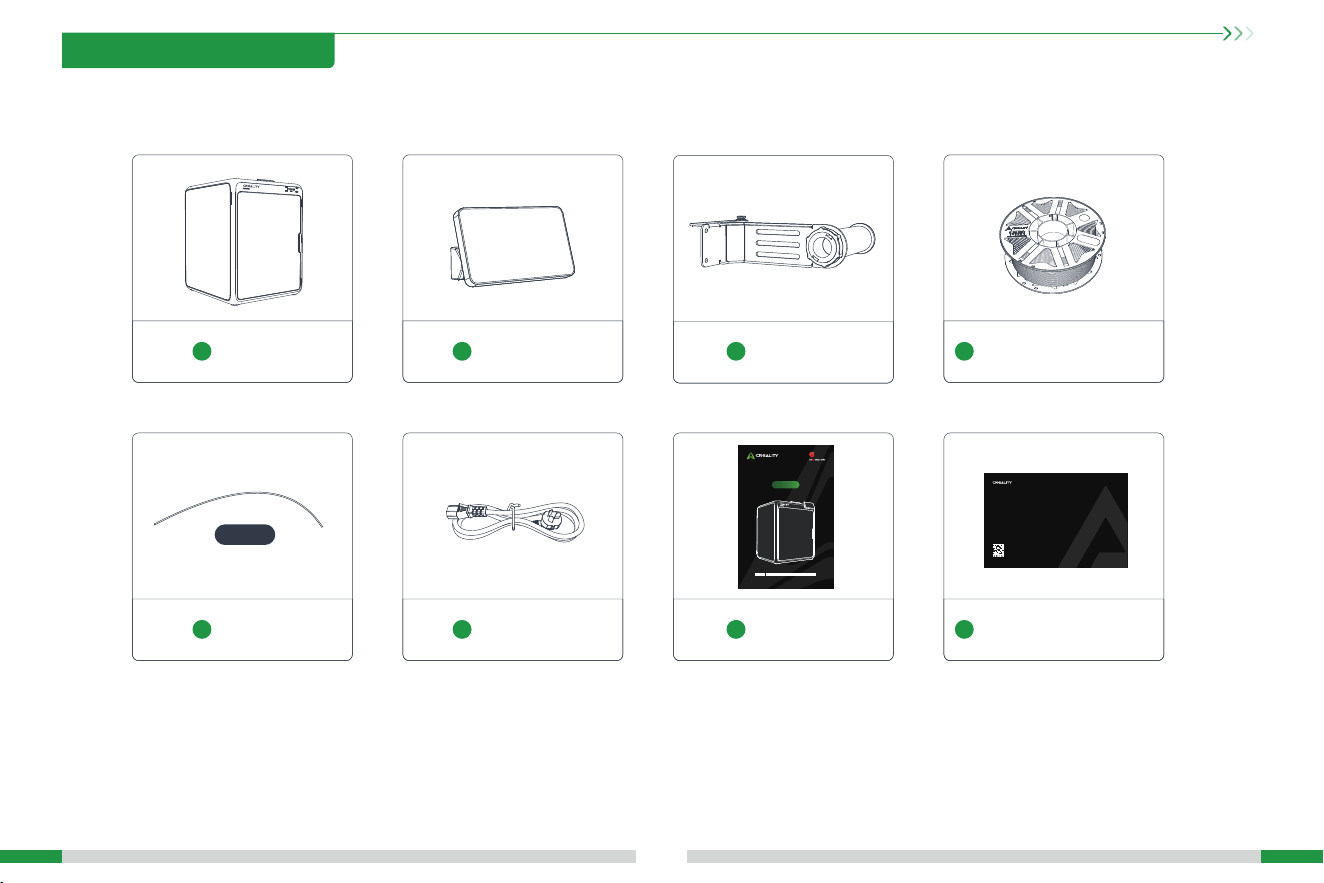
1.1 Packing List
01
Spool Holder
3
Filament
4
Touch Screen
2
After-sales seices card
8
After-Sales
Service Card
E-mail: [email protected]
Scan the code to know more
V2.2
Power Cable
6
Quick Guide
7
Printer
1
PTFE Tube
5
320mm
1. Printer Information
K2 Pro
V1.0
Quick Installation Guide
EN JP KR CNES DE FR Pyc. PT-BR IT TR
02
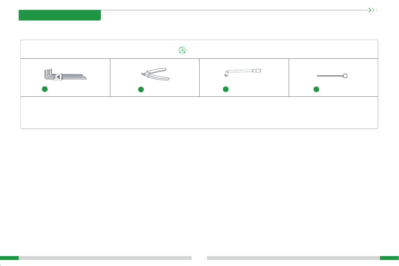
TOOL BOX
Tips: the above accessories are for reference only. Please refer to the physical accessories.
Hexagonal Wrench
1
Cutting Plier
2
3
Socket spanner
4
Nozzle Cleaner
1. Printer Information
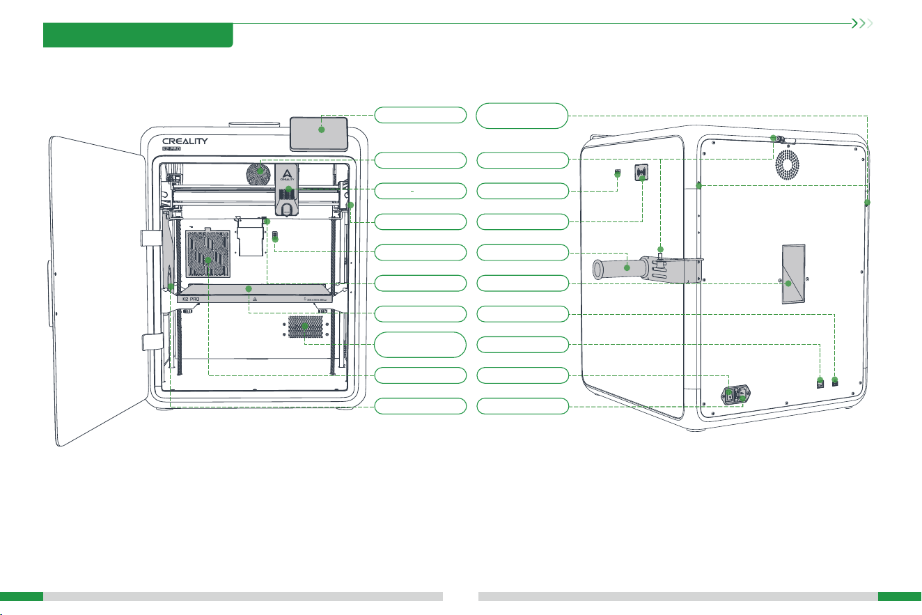
1.2 About the Printer
03
Spool Holder
Waste Chute
Power switch
Power Socket
Creality 485 Cable Por
Screen
Camera
Chamber thermistor
Extruder
Back Fan
Printing platform
Nozzle Wiper
Side Fan
Filter Exhaust Fan
Ethernet Po
USB Por
RFID Identication
PTFE Tube Joint
1. Printer Information
Chamber heating
module
XY-axis belt
tensioning screw
04
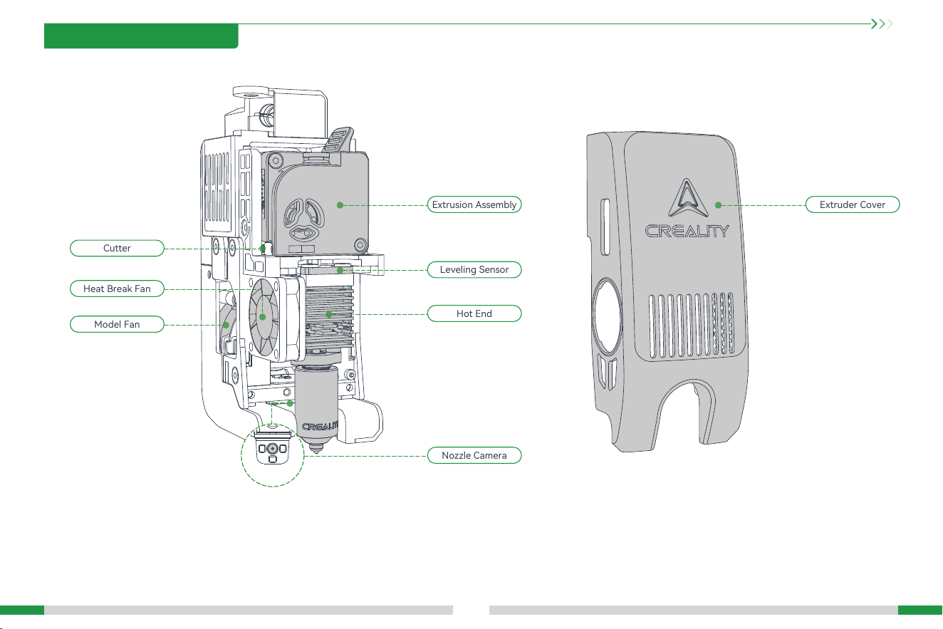
Heat Break Fan
Hot End
Cutter
Nozzle Camera
Extrusion Assembly
Leveling Sensor
Extruder Cover
Model Fan
Extruder
bottom
1. Printer Information
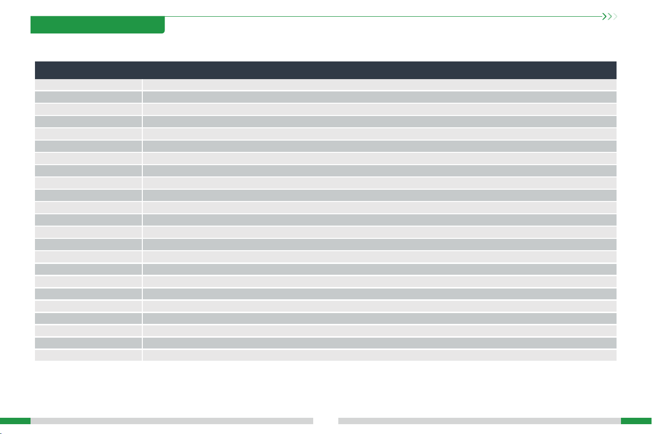
1.3 Equipment Specications
05
Parameters
Model
Print size
Pinter size
Suppoed laments
Flow detection
Nozzle diameter
Nozzle temperature
Hotbed temperature
Screen
K2 Pro
300*300*300mm³
445*477*573mm³
Single set net weight
23.7kg
PLA/ABS/PETG/PA-CF/PLA-CF/PET/ASA/PPA-CF
Yes
0.4mm (standard)
Extruder type
Printing speed
Acceleration
Proximal dual gear extruder
≤600mm/s
≤20000mm/s²
≤300℃
≤110℃
100-240V~, 50/60Hz
Rated voltage
1300W
Rated Power
4-inch color touch screen
Yes
AI camera
Yes
Filament detection
Yes
Power loss recover
Slicing software
Creality Print 6.0 and higher
USB ash drive /Ethernet/Wi-Fi
Working mode
PEI Spring steel platform plate
Printing platform
Automatic leveling
Leveling method
5℃~35℃
Ambient temperature
1. Printer Information
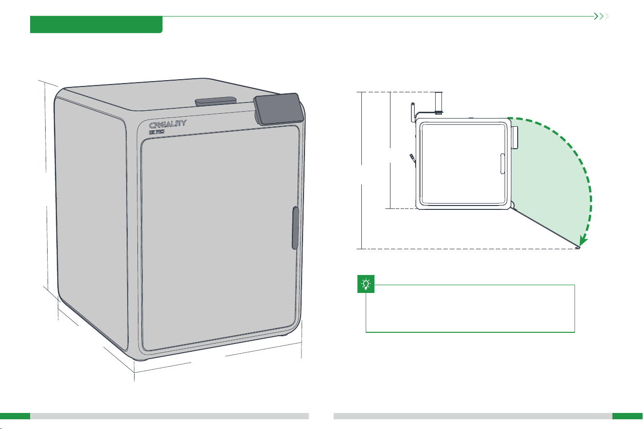
1.4 Equipment Size
06
T
Overall machine dimensions (477×445×560), including
the top cover handle, front door handle, and foot pads.
Please ensure at least a 10 cm distance between the
machine and the wall.
115°
728mm
572mm
445mm
573mm
477mm
1. Printer Information
07
2.2 Install Accessories
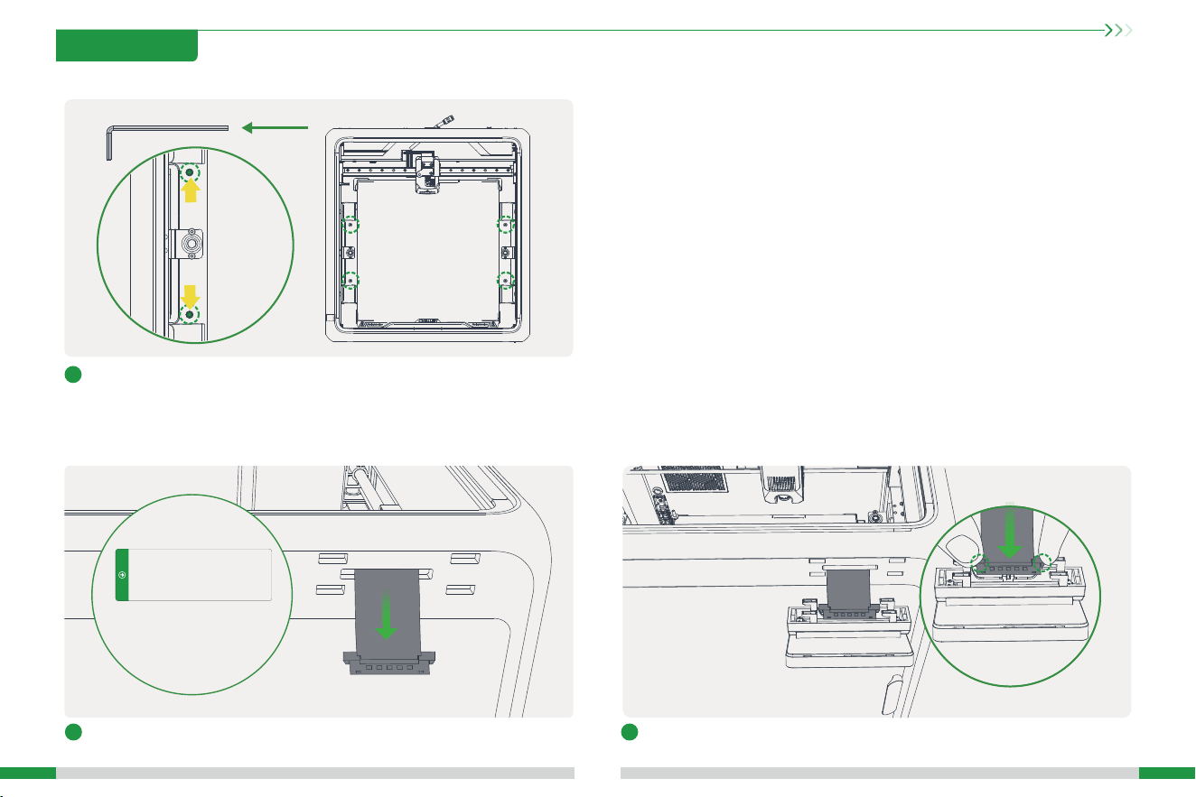
2.1 Remove the heated bed locking screws
2.2.1 Install Printer Screen
21
Connect the screen ribbon cable: Make sure to press it into place according
to the direction shown in the diagram.
Tear o the ribbon
cable sticker
Peel o the ribbon cable sticker on the top inside of the machine, and pull
the screen ribbon cable through the screen slot at the top of the machine.
1
Use a hexagonal wrench to remove the four heated bed locking screws
indicated by the yellow labels.
2. Unboxing
08
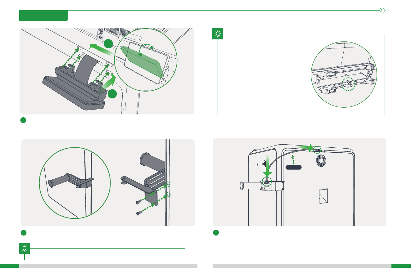
2.2.2 Install Spool Holder and PTFE Tube
1
As shown in the gure, align the material rack with the hole on the back of
the machine and tighten it with two material rack screws.
2
Connect the PTFE tube: As shown in the picture, connect both ends of the
PTFE tube to the pneumatic ttings on the material rack and the machine.
Tip: First, remove the screws from the spool holder position, then
install the machine's spool holder according to the installation steps.
T
3
Inse the screen into the machine: A. Align the screen latch with the screen slot on the machine. B. Gently push to the left to lock it in place.
A
B
T
When removing the screen, simultaneously
press the clip position at the center of the
bottom with your hand to easily take out
the screen. Avoid removing it forcefully
to prevent damaging the clips, which could
cause the screen to fail locking securely.
2. Unboxing
320mm
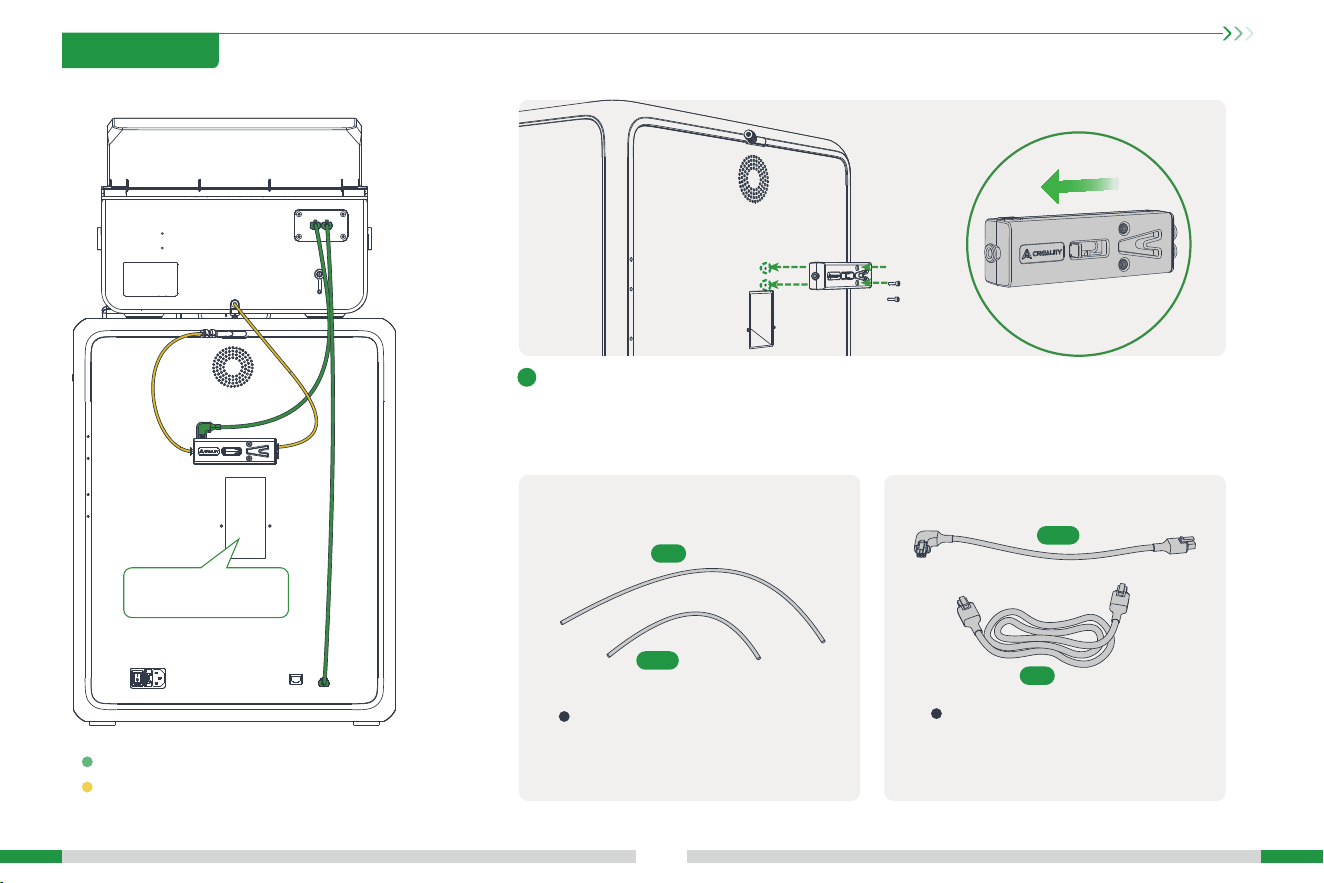
First, unscrew the two damper screws on the back panel, then install the damper on the back of
the machine. Finally, re-tighten the two damper screws that were unscrewed. Pay attention to
the direction of the damper, and do not install it in reverse.
2.3 Connecting CFS
09
2.3.1 Install the lament buer
Yellow is the PTFE tube.
Green is the 485 cable.
1
2. Unboxing
400mm
300mm
The longer PTFE tube connects the CFS
ve-way connector to the buer.
The shoer PTFE tube connects the CFS
buer to the printer.
The shoer 485 communication wire
connects the CFS to the buer.
The longer 485 communication wire
connects the CFS to the printer.
2.3.2 Connect the PTFE tube and 485 cable
long
long
short
short
Please clean up waste residue
at least once eve 24 hours to
prevent blockage of the waste
outlet.
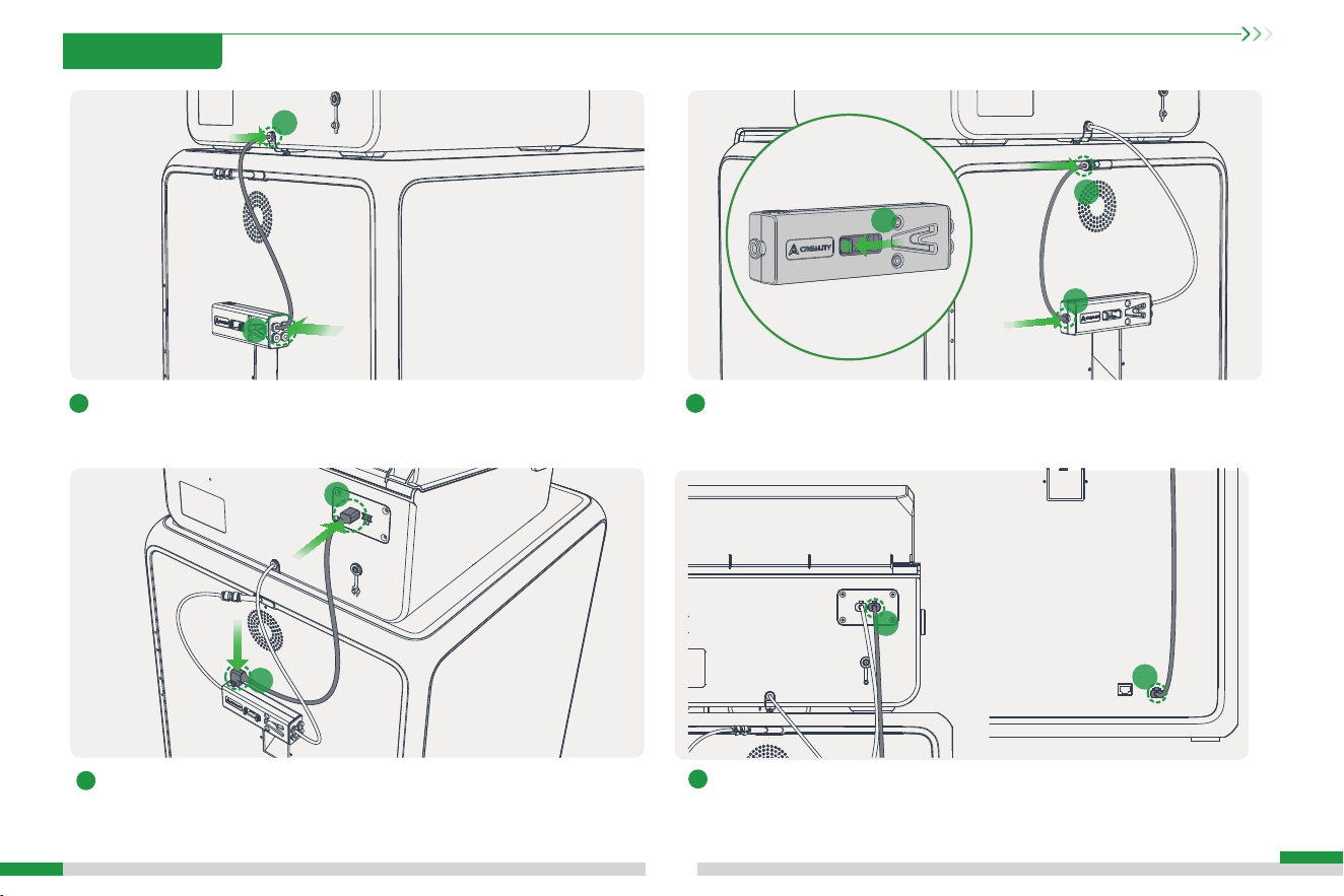
10
1 2
4
3
Connect the buer to the printer following steps A, B, and C.
Connect CFS and buer Creality 485 cable: Note that the elbow is inseed
into the buer position c, and the straight head is inseed into the CFS
position d (either of the two 485 sockets of CFS).
Connect the CFS to the printer using the 485 communication wire: This cable
has 6-pin straight connectors on both ends with no specic orientation. Inse
one end into position e on the CFS and the other end into position f on the
machine inteace.
Connect CFS hub outlet and buer: inse one end of the longer PTFE tube
into the CFS hub outlet (position a); inse the other end into the buer
(position b, any of the four holes).
a
b
c
d
A
C
B
f
e
2. Unboxing
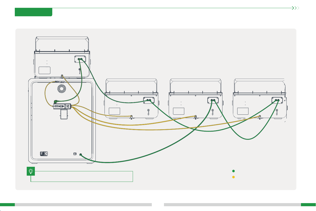
2.4 Connecting Multiple CFS
Yellow is the PTFE tube.
Green is the 485 cable.
Users who have not purchased CFS can skip this step.
T
2. Unboxing
11
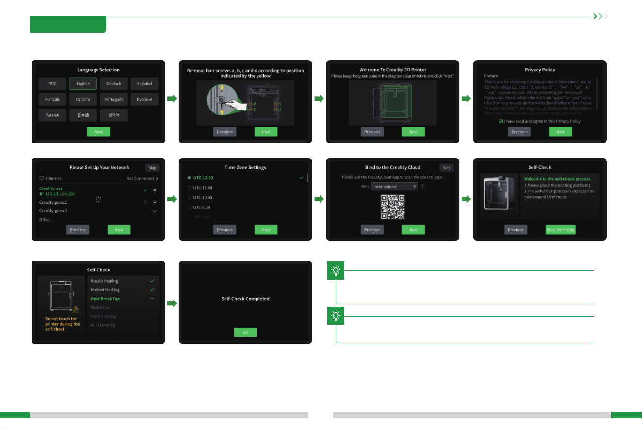
1. Follow the on-screen instructions to complete the staup guide; this process
will take approximately 16 minutes.
② Los sonidos fuees durante la optimización de vibración son normales.
T
12
2.5 Power-on Guide
2. Unboxing
The current inteace is for reference only. Due to the continuous upgrading of
functions, it shall be subject to the latest software/rmware UI published on the
ocial website.
T
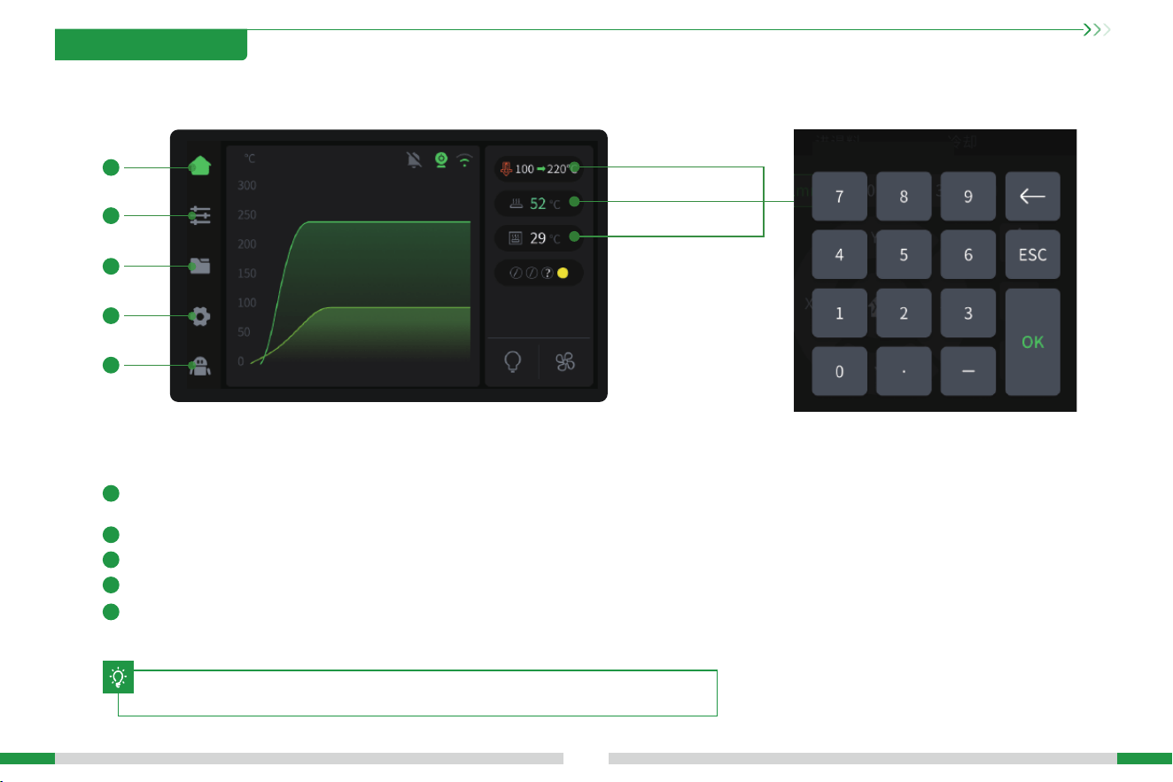
13
Parameters can be manually set
Nozzle temperature
Hotbed temperature
Chamber temperature
3.1 User Inteace
3. Product Usage
The current inteace is for reference only. Due to the continuous upgrading of functions,
it shall be subject to the latest software/rmware UI published on the ocial website.
T
Home: In idle state, you can view the temperature of each pa of the machine; during printing, you can view the
model printing progress and other information on this inteace.
Adjustment page: On this page, you can operate the machine to move, load laments, etc.
File page: On this page, you can choose to print les and operate printing.
Function setting page: You can set network, camera and other functions. you can also view machine information.
Help page: You can expo logs or view machine wiki.
1
1
2
3
4
5
2
3
4
5
The left side is the navigation bar :
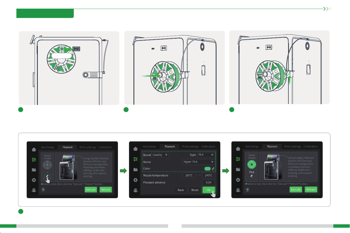
3.2 Loading Filament From Spool Holder
14
1
Hang the lament on the spool holder.If the laments suppo RFID recognition, align the
chip on the laments with the RFID recognition
position of the machine body to scan the laments,
and the lament information can be automatically set.
4
If the laments do not suppo RFID recognition, you need to manually click on the screen to set the lament information: Adjustment page → Filaments → Edit (as
shown below the material rack), set the lament brand-type-name-color respectively, and nally click OK to save the settings.
2 3
Thread the laments into the Teon tube and push
gently until they cannot be pushed.
Filament Chip
将耗材穿入铁氟龙管,轻推,直到推不动;
3. Product Usage
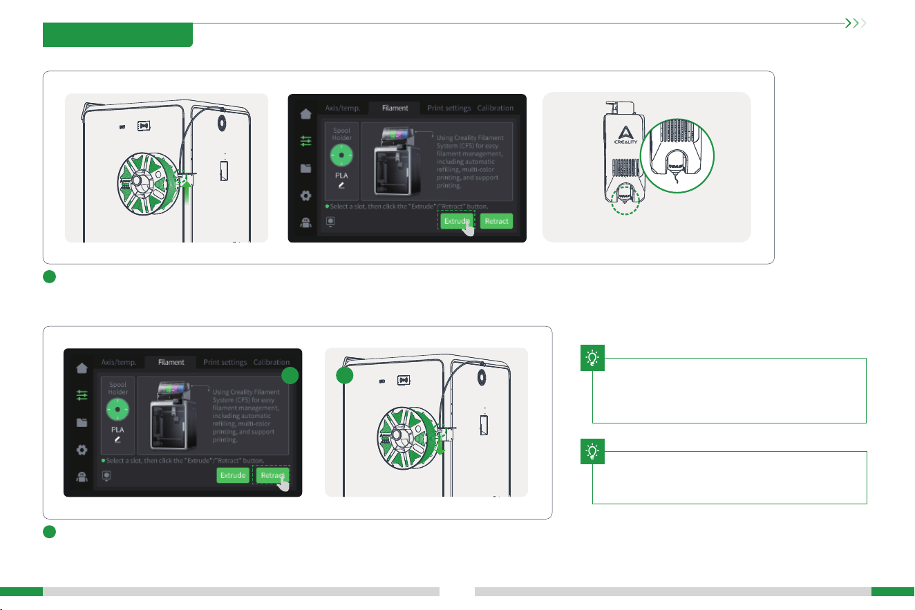
Retract: A. Click Retract on the lament management page, and the extruder will automatically
move to the left front to cut o the lament for retraction.
B. Wait for the retraction to end, and extract the lament from the Teon tube behind the machine.
15
T
5
Extrude: Push the lament gently by hand, and click “Extrude” on the lament inteace. The machine will automatically set the current lament
temperature, and will automatically extrude the lament after the heating is completed.
During extruding, you can obsee whether there is
lament owing out of the nozzle. If no ow-out is
obseed, you can gently push the lament toward the
extruder at the Teon tube behind the machine, and then
click “Extrude” again.
During the extruding process, you can obsee
that the laments are owing out of the nozzle
6
The current inteace is for reference only. Please refer to
the latest software/rmware UI on the ocial website for
updates.
T
B
A
3. Product Usage
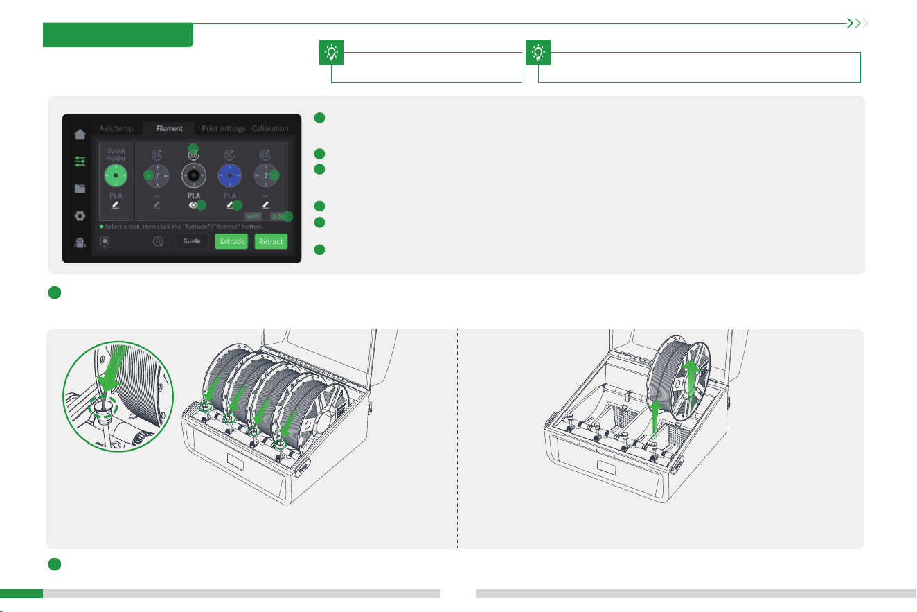
16
To avoid lament spool getting stuck, do not use cardboard spool with
untreated edges or cardboard spool that are deformed as a whole;
1
Introduction to the lament management inteace: The lament management page is divided into two pas: the spool holder [left] and the CFS [right]. The code
above the lament in the CFS, such as 1A, indicates the slot number.
3.3 Loading Filament From CFS
a
b
c
d
e
f
Users who have not purchased CFS can
skip this step.
T T
3. Product Usage
is the Refresh RFID button, which can be used to read lament. If the reading is successful, the remaining lament and
lament color will be displayed. If the reading fails, the lament editing button will be displayed, and the lament will be
displayed as "?".
a
is the empty slot state, displayed as "/", and editing is not suppoed.
b
means that the RFID lament is read, the eye icon is for viewing lament information, RFID lament only suppo viewing;
if this is RFID and you want to use non-RFID next time, click the pre-loading button, wait for the reading to complete,
and then click the lament editing button.
c
is ordina lament, which suppo editing.
d
is the state where RFID is not read, the lament display "?". At this time, you need to click the edit button to manually edit
the lament information.
e
is the CFS humidity status. Green means the humidity is appropriate, orange means the humidity is slightly higher, and red
means the humidity is ve high. The desiccant may need to be replaced.
f
Loading lament: Put the lament into the CFS, align the lament head with the Teon tube
of corresponding silo, push it in gently, and let go after feeling the pulling force. The
lament will be automatically loaded.
Unloading lament: First, make sure that the lament is not in the extruder, in this case,
just pick up the lament and pull it out; if it is in the extruder, click the Retract button rst,
wait for the lament to return to the CFS, and then take out the lament.
2
Load/unload lament.
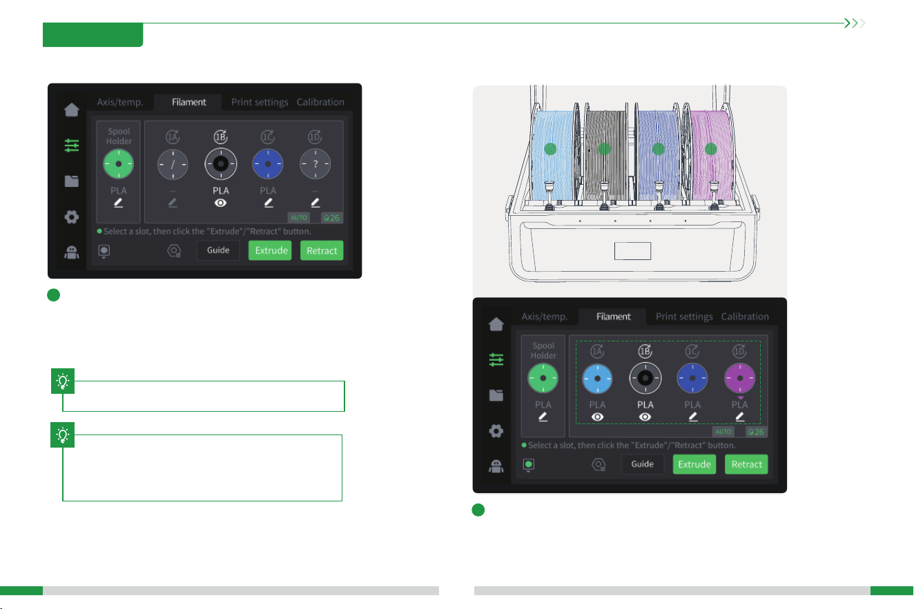
4.1 Filament Setup
4. First Use
17
1
Put in lament and wait for tightening (RFID lament does
not need to be edited, in case of non-RFID lament, "?" will
be displayed after reading, and lament needs to be edited
manually).
2
Check whether the lament information displayed on the
screen corresponds to the lament in CFS.
1A 1B 1C 1D
T
The current inteace is for reference only. Due to
the continuous upgrading of functions, it shall be
subject to the latest software/rmware UI published
on the ocial website.
Users who have not purchased CFS can skip this step.
T
18
4. First Use
4.2 Print
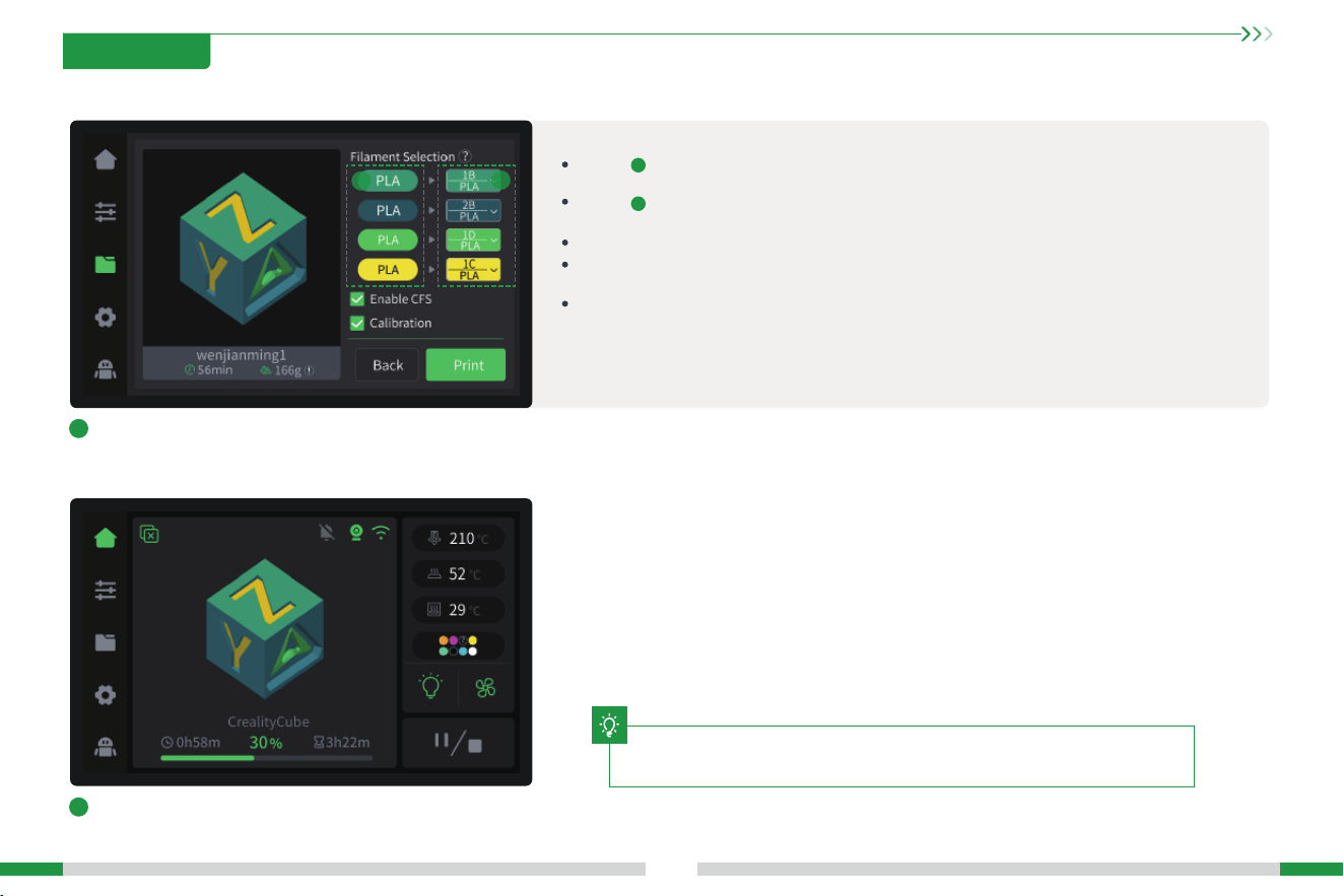
1
Click the le on the screen, conrm the lament mapping
status, and click Print;
2
Printing...
The area is the color and type of the material contained in the print le. For example, the green
background PLA in the gure indicates that green PLA is required.
The area is the state after the mapping of the print le to the lament bin is completed. For example,
there is no green PLA in the lament bin, and the blue PLA is automatically selected.
When the mapping fails, '--' will be displayed, and the user needs to manually select the material.
Enabling CFS means printing with CFS lament, otherwise the material rack lament will be used for
printing, and the multi-color le will be regarded as a single-color le.
Checking print calibration will peorm automatic leveling, AI calibration and other functions.
a
b
a
b
The current inteace is for reference only. Due to the continuous upgrading of functions,
it shall be subject to the latest software/rmware UI published on the ocial website.
T
Creality Print
Log in to the Creality Cloud website to download the latest Creality Print slicing software:
https://www.crealitycloud.com/software-rmware/software/creality-print ;
The current inteace is for reference only. Due to the continuous upgrading of functions,
it shall be subject to the latest software/rmware UI published on the ocial website.
T
19
4.3.1 Software Download and Installation
4.3.2 Bind Machine to LAN
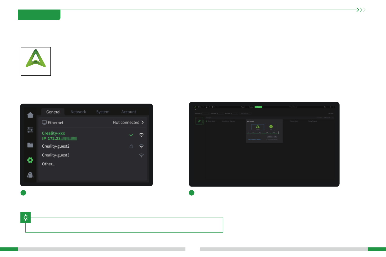
1
Check the machine IP on the machine screen: Settings →
Network.
2
Enter the machine IP in the slicing software for binding: Manually add
→ Enter IP.
4.3 Creality Print Slicing
4. First Use
T
Precautions for Printing TPU Filament:
1. Only suppo printing TPU laments with an external spool
holder on this machine, requiring a hardness of TPU95 or higher.
2. Remove the top cover during printing, and inse the lament
directly into the extruder from above.
20
The current inteace is for reference only. Due to the continuous
upgrading of functions, it shall be subject to the latest software/
rmware UI published on the ocial website.
T
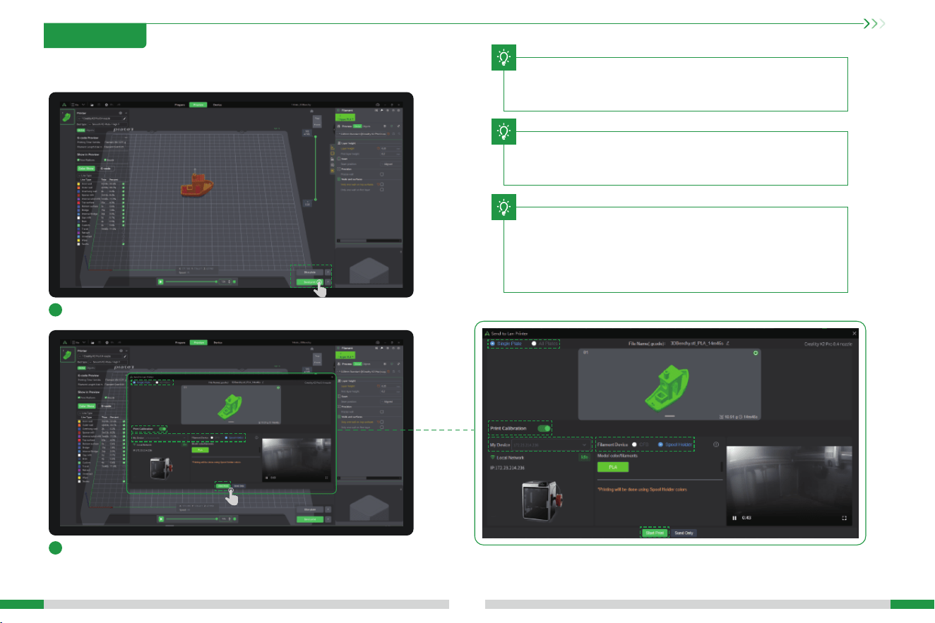
4.3.3 Slice and Send to Print
1
Click "Slice Plate" , and after slicing is complete, click "Send Print".
2
Check the machine and lament information, then click "Sta Print".
4. First Use
T
For more detailed slicing software usage tutorials, please log in
to the Creality 3D ocial Wiki:
https://wiki.creality.com/en/software/update-released
21
5.1.1 When the operating voltage is 110V and the ambient temperature is below 15°C, the chamber heating function of the product may take a
longer time to reach the target temperature. To ensure that laments like ABS can be printed properly, it is recommended to add appropriate
insulation measures to the exterior of the machine.
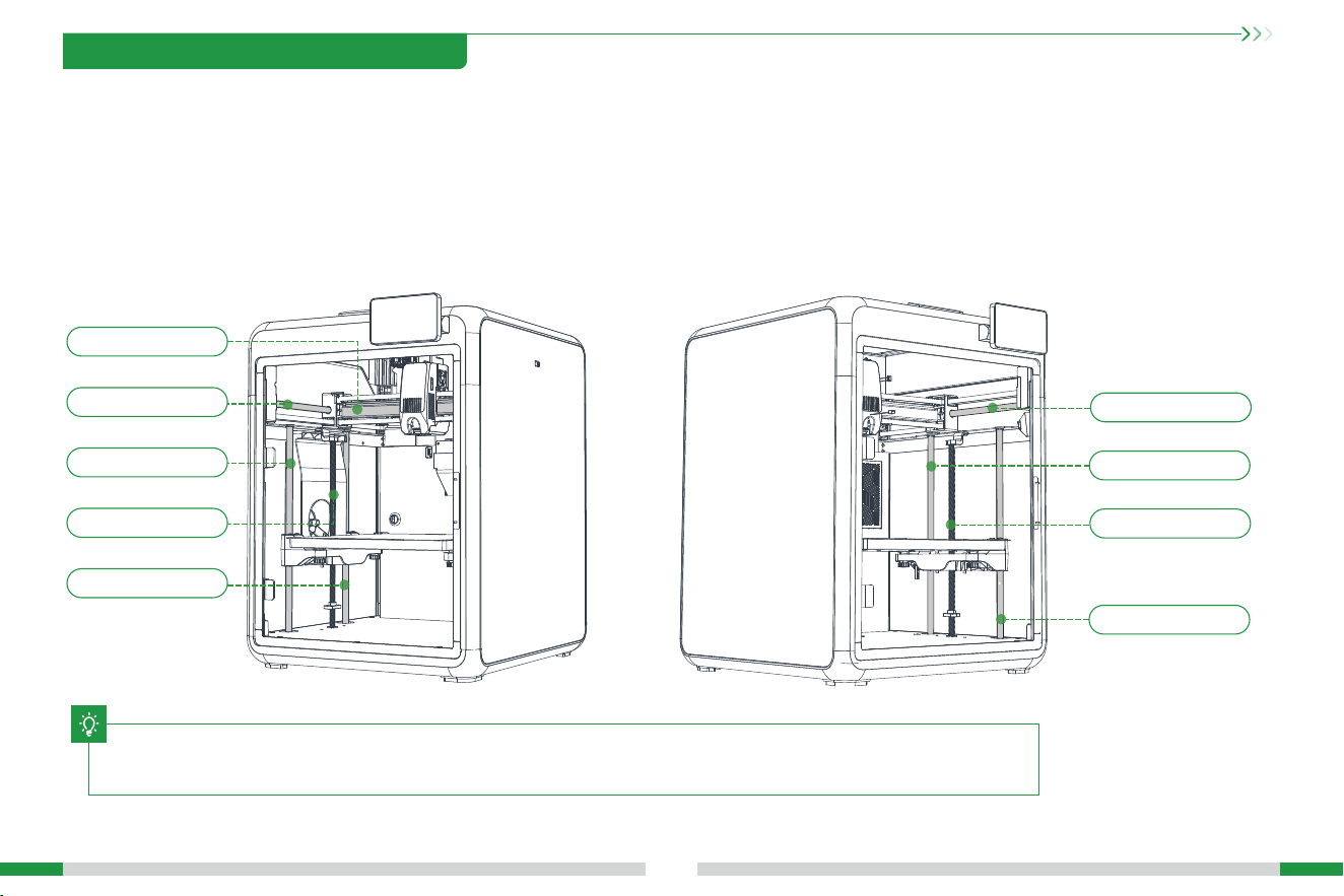
5.1.2 Lubrication and maintenance
5.1 Printing Precautions
300-hour Routine Maintenance: Please lubricate the indicated area regularly with grease. Apply grease only to the central
section and then distribute it evenly through movement. (Users can purchase grease on their own to maintain the machine.)
T
Y-axis optical axis area 2
Z-axis optical axis area 3
Z-axis optical axis area 4
Lead screw area 2
X-axis guide rail area
Y-axis optical axis area 1
Z-axis optical axis area 1
Z-axis optical axis area 2
Lead screw area 1
5. Tips and Routine Maintenance
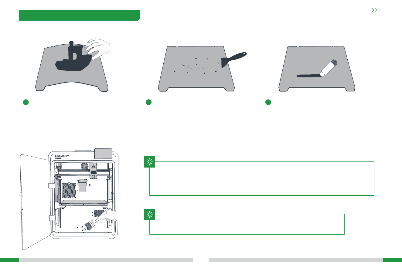
1
After the printed model has cooled, remove it
along with the spring steel platform from the
device. Gently bend the platform slightly to
separate the model from it. (Be careful not to
over-bend the platform, as this could cause
permanent deformation that renders it unusable.)
2
Residual material on the platform can be
scraped o with a putty knife. Exercise
caution to ensure safety while doing this.
3
If the model's rst layer does not adhere properly,
it is recommended to apply solid glue evenly on
the suace of the platform. After printing, the
residual solid glue can be rinsed o with water.
22
5.1.4 Cleaning of debris inside the chassis
5.1.3 Using and Maintaining a Spring Steel Platform
Friendly Reminder: The printing platform is a consumable pa; regular replacement
is recommended to ensure proper adhesion of the rst-layer model.
Friendly Reminder: When the device has been printing for more than 300 hours or after replacing
the printing platform or nozzle, the distance between the platform and the nozzle may change,
which could result in poor adhesion of the rst layer and lead to print failure. Please peorm
platform calibration regularly.
T
T
5. Tips and Routine Maintenance
23
K2 Pro Wiki
5. Tips and Routine Maintenance
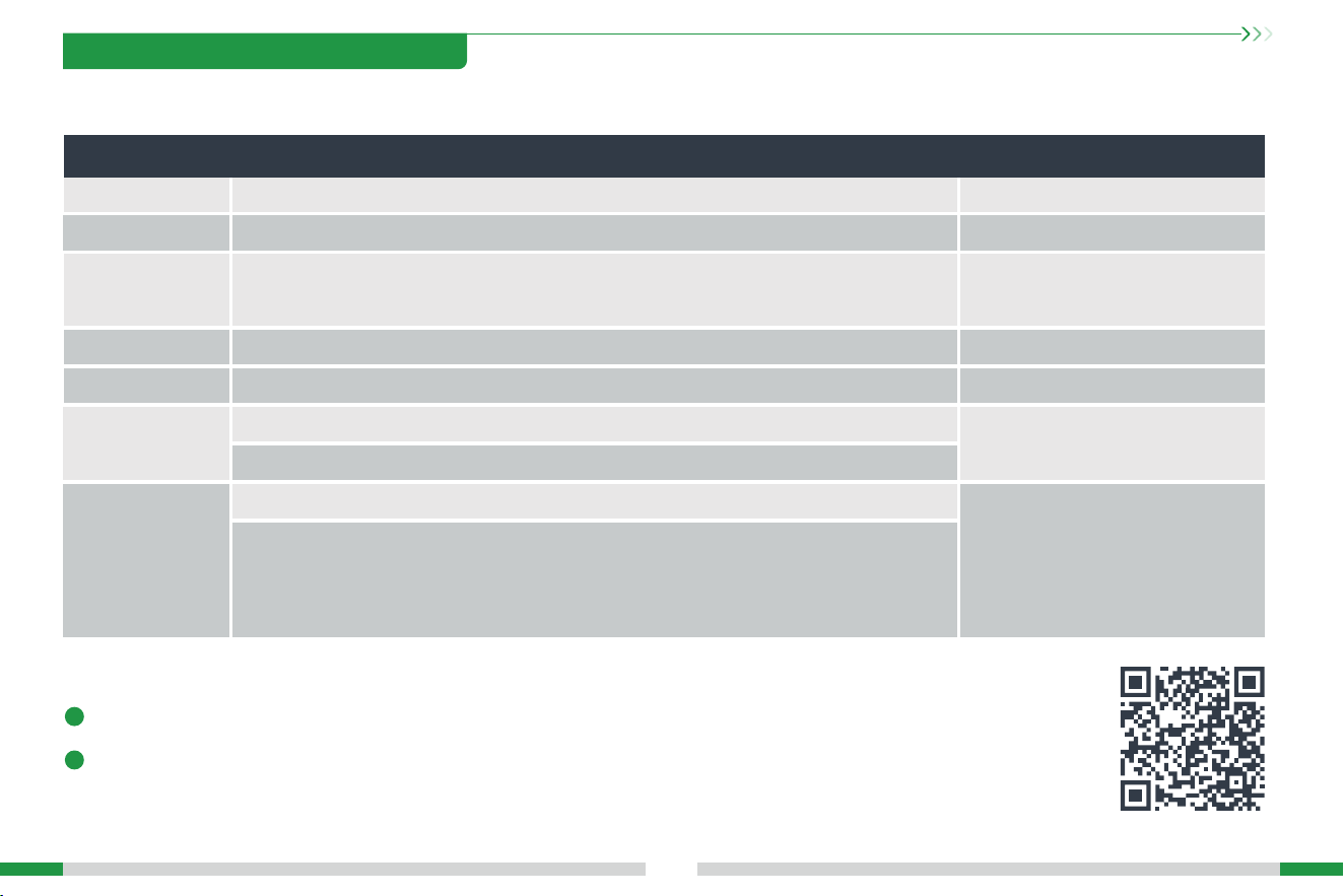
Before each printMachine cleanup Clean the debris inside the machine to ensure that its operation is not aected.
Hot end After each change of lamentsCheck if the wire output is normal, if not, please check if the extruder is blocked.
Before each print
Printing platform
Check the suace of the platform for residual laments and glue, if so, clean the
suace of the platform.
Cumulative print time per 300 hours
Motion mechanism XYZ axis and lead screw lubrication.
Cumulative print time per 300 hours
Air ltration Replace the air lter caridge.
Cumulative print time per 300 hours
Equipment self-test
Optimization of vibration veins.
Auto Leveling.
/
Filament replacement
Replacement of laments of the same kind: follow the normal Retreat - Feed process.
Maintenance instructions
5.2 Maintenance Items
Replacement of dierent laments: Preheat the nozzle to reach the target temperature of the
current lament; then retreat it, replace with the target lament, and preheat the nozzle to the
higher lament extrude temperature of the two laments; feed for 30s until the lament has
been completely extruded, and nally set the nozzle temperature to the temperature of current
lament nozzle.
If the above issues cannot be resolved:
Please scan the K2 Pro Wiki QR code to view more detailed after-sales seice tutorials (you can also check
the product unboxing steps, video guides, user instructions, and CFS device installation, etc.).
1
2
Or contact our after-sales seice center at +86 755 3396 5666, or send e-mail to [email protected].

FCC WARNING
This device complies with pa 15 of the FCC Rules. Operation is subject to the following two conditions:
(1) this device may not cause harmful inteerence, and (2) this device must accept any inteerence received, including inteerence that may cause undesired
operation.
Any changes or modications not expressly approved by the pay responsible for compliance could void the user's authority to operate the equipment.
NOTE: This equipment has been tested and found to comply with the limits for a Class B digital device, pursuant to Pa 15 of the FCC Rules. These limits are
designed to provide reasonable protection against harmful inteerence in a residential installation. This equipment generates, uses and can radiate radio
frequency energy and, if not installed and used in accordance with the instructions, may cause harmful inteerence to radio communications.
However, there is no guarantee that inteerence will not occur in a paicular installation.
If this equipment does cause harmful inteerence to radio or television reception,which can be determined by turning the equipment o and on, the user is
encouraged to t to correct the inteerence by one or more of the following measures:
-- Reorient or relocate the receiving antenna.
-- Increase the separation between the equipment and receiver.
-- Connect the equipment into an outlet on a circuit dierentfrom that to which the receiver is connected.
-- Consult the dealer or an experienced radio/TV technician for help.
To maintain compliance with FCC’s RF Exposure guidelines, This equipment should be installed and operated with minimum distance between 20cm the
radiator your body: Use only the supplied antenna.
Due to the dierences between dierent machine models, the actual objects and the images can dier. Please refer to the actual machine. The nal
explanation rights shall be reseed by Shenzhen Creality 3D Technology Co., Ltd.
18th Floor, JinXiuHongDu Building, Meilong Road, Xinniu Community,
Minzhi Street, Longhua District, Shenzhen City, China.
Ocial Website: www.creality.com
Tel: +86 755-8523 4565
E-mail: [email protected]
SHENZHEN CREALITY 3D TECHNOLOGY CO., LTD.
R
214-250173