Quick Sta Guide
Note: Do not power on the printer before installation is complete.
Please read this guide carefully before using the product.
V1.0
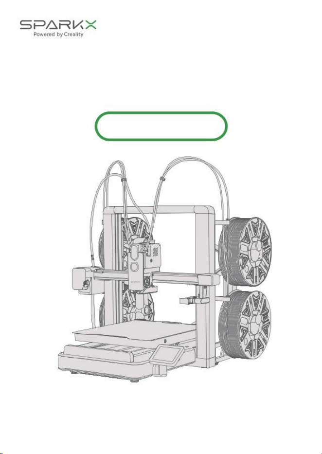
SPARKX i8
Thank you for choosing SPARKX products!
For detailed after-sales seice information, please visit our ocial
website (www.creality.com) or scan the QR code below.
Seice PolicyCreality Ocial Website
SPARKX Wiki
Download Creality Cloud
Download Creality Print
Discover Premium Models
Let's Begin Your Printing Journey!
Scan the QR Code.
After-Sales Seice Guide
You can also reach us for help and suppo through the following
channels:
Global Seice Hotline:1-833-513-5012
Global Seice Email: cs@creality.com
You may also visit the Creality Wiki (https://wiki.creality.com) to explore
more detailed after-sales tutorials.
Creality will continue to improve and optimize its after-sales seice
policies and update them promptly on ocial platforms. Please stay
informed. Creality resees the right to interpret these policies.
1
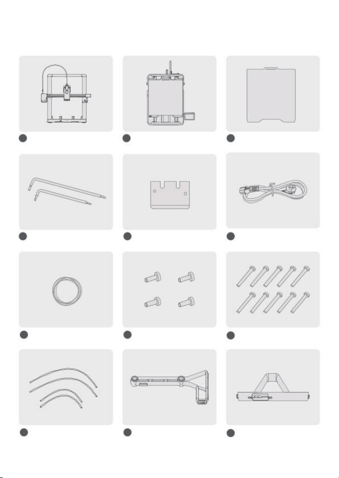
/ Packing List
Print plate
Hex wrench Scraper Blade Power cable
4 5 6
1 2 3
Printer Frame
7
Filament sample
8
M3×8 Screw*4
Base Housing
M3×34 Screw*10
9
H2.5
H2.0
10
60cm PTFE tube*2
80cm PTFE tube*2
11
Main bracket*2
Bridge connector*2
12
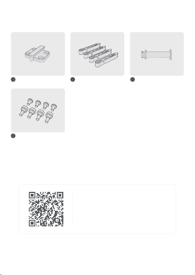
Spool holder*4
Spool Rack Mounting Screws:
M3×6 Screws*4
Shoulder Screws*4
16
13 14 15
Slide buckle*2 Pneumatic tting
connector
* The above list is for reference only.
Please refer to the actual items received.t
* Note: We strongly recommend scanning
the QR code to view the installation Wiki
and video for better guidance during the
printer assembly.
2
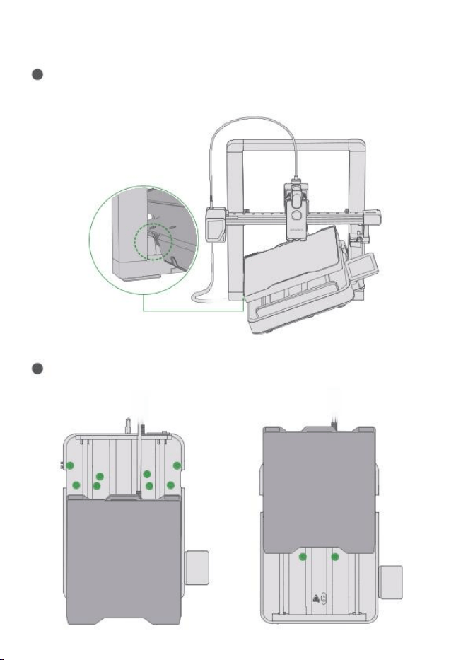
/ Install the Printer
Take out the Printer Frame and the Base Housing. Inse the Base Housing
through the Printer Frame and press it downward until it clicks into place.
1
After the assembly is in place, use an H2.5 hex wrench to tighten the
10*M4×34 screws on the top of the base. You may move the heated bed forward
and backward to facilitate the operation.
2
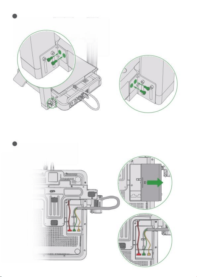
Use an H2.0 hex wrench to tighten the 2*M3×8 screws on each side.
3
Open the bottom mainboard cover, connect the signal cables to their
corresponding pos, and reinstall the cover after the connections are completed.
4
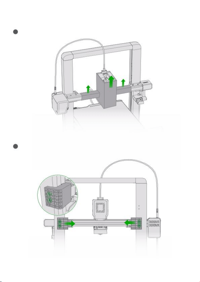
Take o the protective cardboard from the X-axis and toolhead.
1
3
/ Unlock the X-Axis
Use the H2.0 hex wrench to remove the four screws securing the two X-axis
transpo brackets at the rear of the printer, then remove both brackets.
2
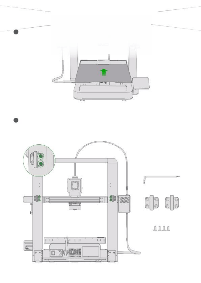
4
/ Install the print plate
Place the print plate in the orientation shown, ensuring that its edges are
aligned with the heated bed.
1
5
/ Install the spool rack
Take out four M3*6 screws and two slide buckles.Using the H2.0 hex key, install
the two slide buckles into the screw holes on the left and right rear sides of the
gant. Note that these are the second set of screw holes from the top of the
gant, as shown below;
1
H2.0
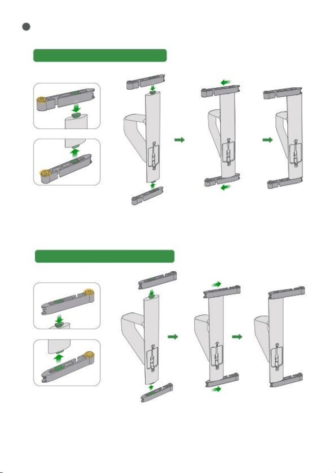
Take out four pneumatic tting connectors and two bridge connectors, and
assemble the left and right bridge connector assemblies as shown below;
2
Left bridge connector installation:
Right bridge connector installation:
Note: Keep the
pneumatic tting
facing upward.
Note: Keep the
pneumatic tting
facing upward.
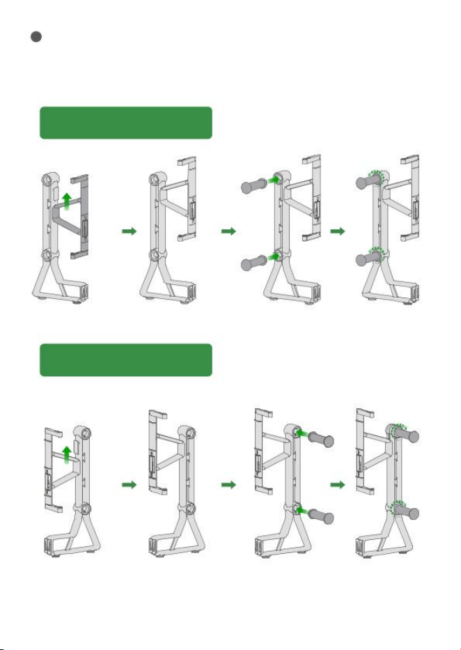
Slide the left bridge connector into the main bracket from bottom to top,
then screw in the spool holder counterclockwise in the direction shown.
Use the same method to assemble the right bridge connector, main bracket,
and spool holder;
3
Left bridge connector, bracket,
and spool holder installation:
Right bridge connector, bracket,
and spool holder installation:
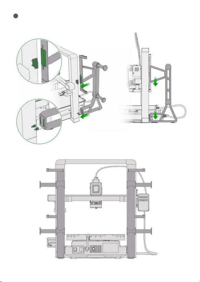
Slide the assembled right spool rack down into the slide buckles and shoulder
screws, and make sure it is fully seated;
4
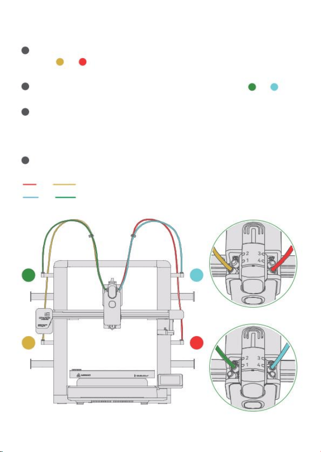
As shown, inse the two longer PTFE tubes (80 cm) into pneumatic
ttings and below the spool holders on both sides. The openings in
the upper pneumatic ttings can be used to help secure the tubes.
1
1 4
As shown, inse the two shoer PTFE tubes (60 cm) into pos and 3
above the spool holders on both sides.
2
2 3
Following the color coding, connect the PTFE tubes from the spool holders
to the correspondingly numbered channels on the toolhead.
Impoant: Make sure each tube is connected to the correct channel, as
incorrect connections may aect subsequent operation.
3
Use the included cable clips to secure and organize the PTFE tubes.
4
6
/ Connect the PTFE Tubes
Red and yellow: 80 cm PTFE tubes.
Blue and green: 60 cm PTFE tubes.
3
4
2
1
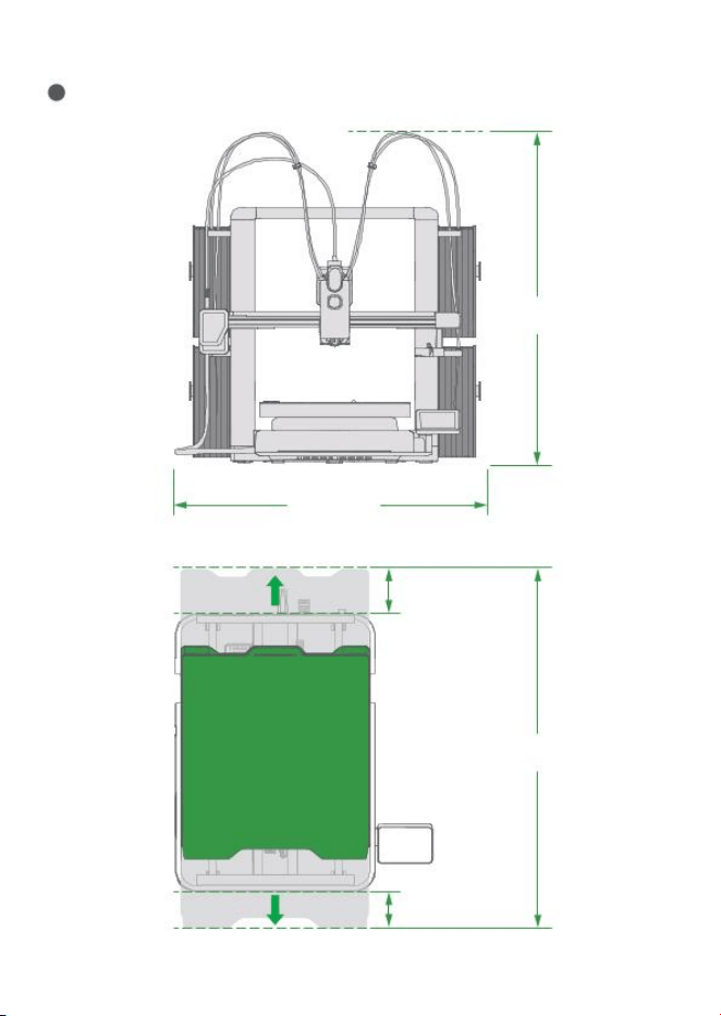
Completed installation shown below. Leave sucient operating clearance.
5
≥743mm
≥120mm
200mm
≥630mm
≥550mm
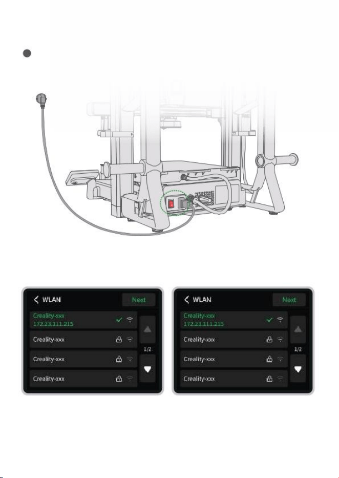
Plug in the power cable and press the power switch on the back of the machine.
1
7
/ Power On
8
/ Connect to Network
a. Follow the on-screen instructions
until you reach this page, then select
the network you want to connect to.
b. After connection, you can enjoy
more online seices.
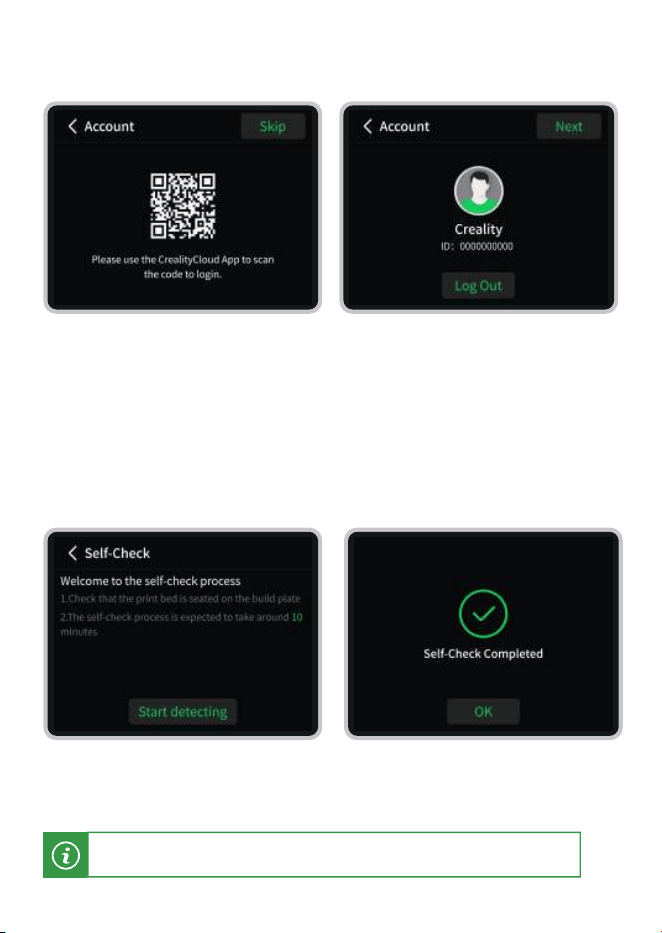
a. Scan the QR code on the printer
screen to download the Creality Cloud
App. Register and log in to your
Creality Cloud account.
b. Use the Creality Cloud App to scan
the QR code on the printer screen,
and follow the instructions in the App
to complete account login.
9
/ Log in to Account
b. Wait patiently until the self-check is
completed, then you can sta using
the printer.
10
/ Printer Self-check
a. Follow the on-screen prompts to
sta the device self-check.
During the self-check, vibration and noise are normal phenomena.
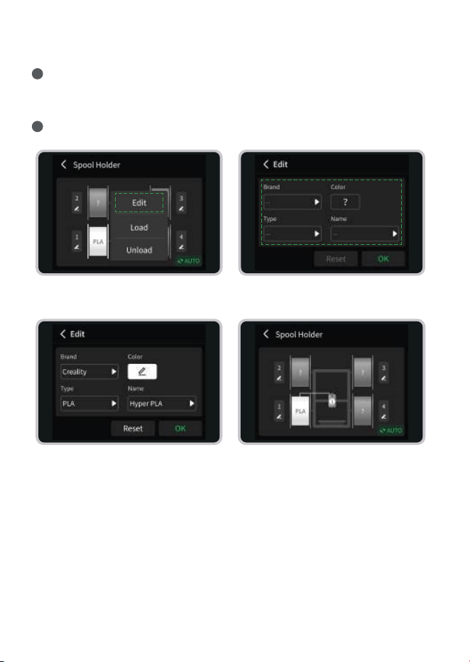
Place the lament spool on the spool holder. Inse the lament into the
corresponding inlet and feed it through the PTFE tube until it reaches the
toolhead and cannot be pushed any faher.
1
Go to the Filament page and tap the Edit button to modify lament information.
2
11
/ First Print Experience
a. When the lament shows a
question mark, tap Edit.
c. After completing the lament
information setup, click Conrm.
d. The lament parameters are now set.
b. Set the Brand – Color – Type –
Name of the lament.
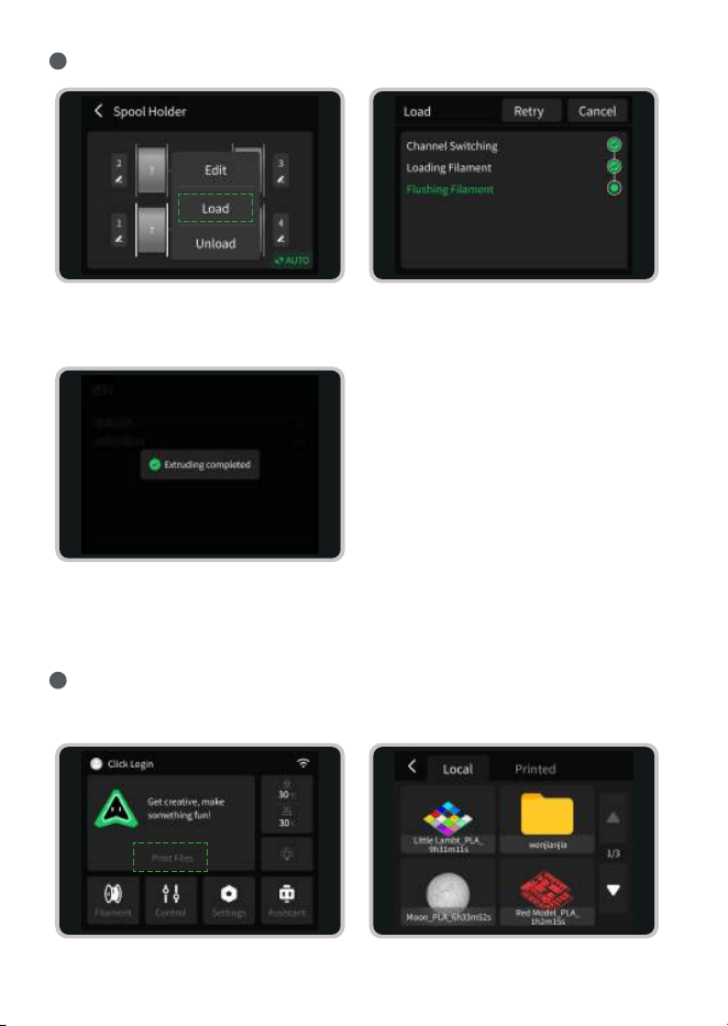
Load each required lament in sequence.
3
a. Select the lament to be loaded,
then tap “Load.”
b. Wait for loading to complete.
Gently push the lament by hand to
ensure successful loading.
c. Filament loading completed.
Repeat these steps for each lament
you plan to use.
* Before printing, ensure the print plate is placed at and free of debris.
Sta Printing
4
a. On the Home page, tap Print File. b. Select the model you want to print.
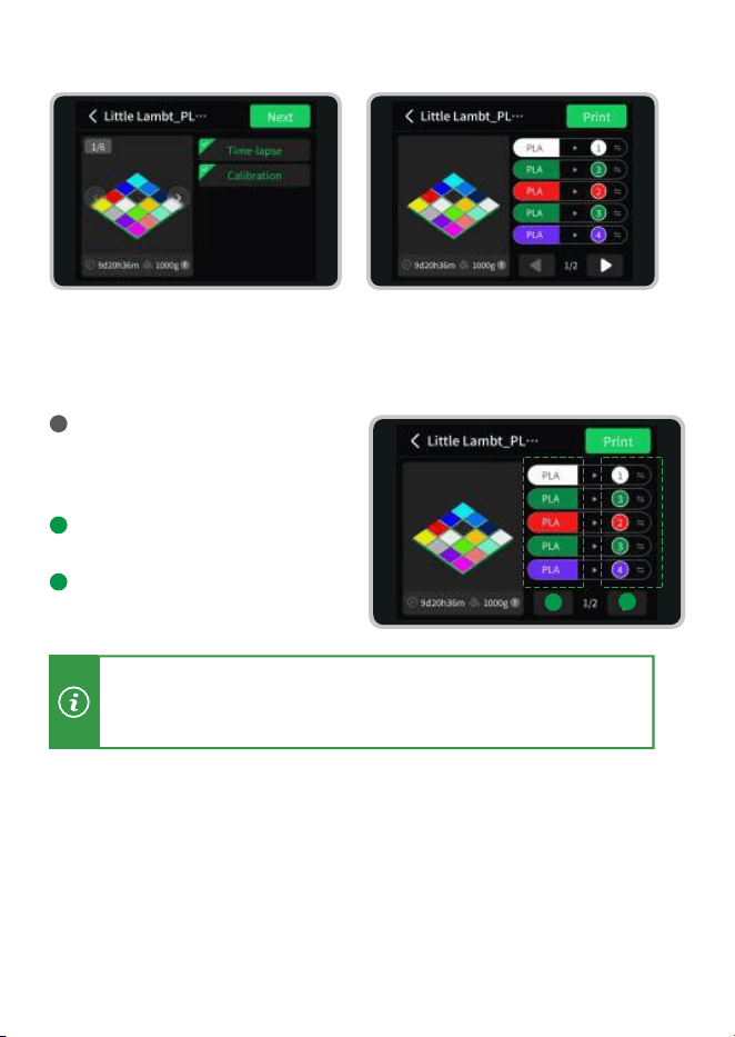
For multi-color printing, you need
to map the actual lament to the
lament set in the print le.
Represents the lament set in
the print le.
Represents the actual lament
in use.
c. Tap NEXT (It is recommended to
enable the Print Calibration option).
d. Tap Print.Wait patiently for the
printing to complete. (After printing,
allow the print bed to cool down
completely before removing the model.)
Filament Mapping Instructions
5
It is recommended to use actual lament colors as close as possible
to the ones dened in the print le, otherwise purging results may
be aected.
a
a
b
b
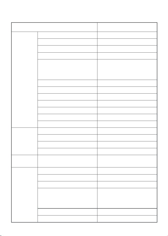
Basic
Information
Speed
Suppoed
Filament
Feature
Conguration
Model
Brand
Printing Technology
Body Material
Input Voltage / Power
Physical Dimensions (W×D×H)
Net Weight
Build Volume (W×D×H)
Display
Monitoring Camera
Pos
Storage
Optimized Print Speed
Optimized Acceleration
Max Print Speed
Max Acceleration
Input Shaping
Filament Runout Detection
Filament Runout Recove
AI Monitoring
Empty Extrusion Monitoring
Cutter Status Detection
Suppoed
Suppoed
Suppoed
Suppoed,including build
plate detection, spaghetti
detection, and other features
Suppoed
Suppoed
PLA/PLA-Silk/PLA-CF/PETG Recommended
300mm/s
10000mm/s²
500mm/s
10000mm/s²
SPARKX i8
SPARKX
FFF
Metal、Plastic
100-240V~ AC 50/60Hz
Rated Power:110-130W
Max Power:320-870W
470*423*456mm³
9.72kg
260×260×255mm³
2.85 inches 640*480 IPS Touch Screen
720P with LED ll light
Creality 485 6pin
8GB,Micro SD
Item
12
/ Technical Specications
Specification
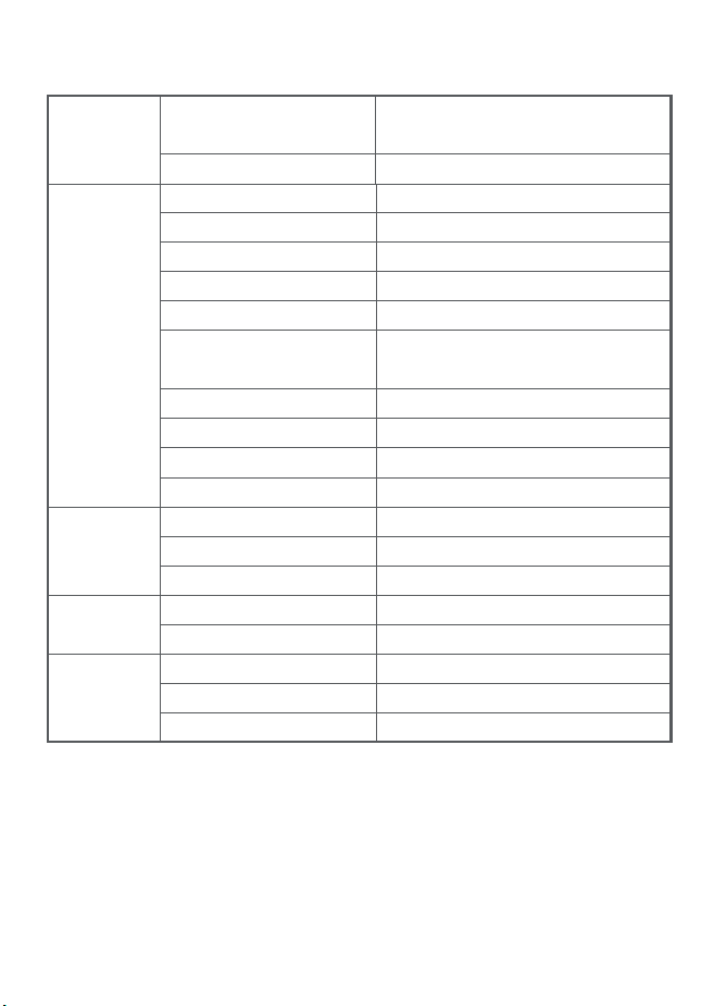
Toolhead
Software
Wi-Fi
Hotbed
Number of Hot Ends
Extruder
Quick-Release Hotend
Cutter
Max Hot End Temperature
Nozzle Diameter
Hot End Material
Model Cooling Fan
Hotend cooling fan
Max Hot End Flow
Max Print Plate Temperature
Hotbed Power
Print Plate
Slicer
Creality Cloud APP
Frequency Range
Power
Protocol
1
Direct Drive Extruder
Suppoed,Tool-Free Quick Release
Stainless Steel
300℃
0.4mm(Included),
0.2/0.6/0.8mm(Optional)
Hardened Steel
Silent Fan
Silent Fan
25mm³/s (Creality Hyper PLA, 220℃)
100℃
750W@220V / 250W@110V
Dual-Sided Gold Textured PEI Plate
Creality Print 7.0 or later
Suppoed
2.4GHz(2400~2483.5MH)
20.04dBm
IEEE 802.11b/g/n
Feature
Conguration
Intelligent Status
Indicator
Audible Ales
Suppoed,RGB
Suppoed