
ProFace X [TD] User Manual
Page | 1 Copyright©2020ZKTECO CO., LTD. All rights reserved.
Thank you for choosing our product. Please read the instructions carefully
before operation. Follow these instructions to ensure that the product is
functioning properly. The images shown in this manual are for illustrative
purposes only.
For further details, please visit our Company’s website
www.zkteco.com.
User Manual
Biosense Series Network Camera
Date: January 2024
Doc Version: 2.5
English

Biosense Series Network Camera User Manual
Page | 2 Copyright©2024 ZKTECO CO., LTD. All rights reserved.
Copyright © 2024 ZKTECO CO., LTD. All rights reserved.
Without the prior written consent of ZKTeco, no portion of this manual can be copied or forwarded in any
way or form. All parts of this manual belong to ZKTeco and its subsidiaries (hereinafter the "Company" or
"ZKTeco").
Trademark
is a registered trademark of ZKTeco. Other trademarks involved in this manual are owned by
their respective owners.
Disclaimer
This manual contains information on the operation and primarytenance of the ZKTeco Device. The copyright
in all the documents, drawings, etc. in relation to the ZKTeco supplied Device vests in and is the property of
ZKTeco. The contents hereof should not be used or shared by the receiver with any third party without
express written permission of ZKTeco.
The contents of this manual must be read as a whole before starting the operation and primarytenance of
the supplied Device. If any of the content(s) of the manual seems unclear or incomplete, please contact
ZKTeco before starting the operation and primarytenance of the said Device.
It is an essential pre-requisite for the satisfactory operation and primarytenance that the operating and
primarytenance personnel are fully familiar with the design and that the said personnel have received
thorough training in operating and primarytaining the machine/unit/Device. It is further essential for the
safe operation of the machine/unit/Device that personnel has read, understood, and followed the safety
instructions contained in the manual.
In case of any conflict between terms and conditions of this manual and the contract specifications,
drawings, instruction sheets or any other contract-related documents, the contract conditions/documents
shall prevail. The contract-specific conditions/documents shall apply in priority.
ZKTeco offers no warranty, guarantee, or representation regarding the completeness of any information
contained in this manual or any of the amendments made thereto. ZKTeco does not extend the warranty of
any kind, including, without limitation, any warranty of design, merchantability, or fitness for a particular
purpose.
ZKTeco does not assume responsibility for any errors or omissions in the information or documents which
are referenced by or linked to this manual. The entire risk as to the results and performance obtained from
using the information is assumed by the user.
ZKTeco in no event shall be liable to the user or any third party for any incidental, consequential, indirect,
special, or exemplary damages, including, without limitation, loss of business, loss of profits, business
interruption, loss of business information or any pecuniary loss, arising out of, in connection with, or relating
to the use of the information contained in or referenced by this manual, even if ZKTeco has been advised of
the possibility of such damages.
This manual and the information contained therein may include technical, other inaccuracies or
typographical errors. ZKTeco periodically changes the information herein which will be incorporated into

Biosense Series Network Camera User Manual
Page | 3 Copyright©2024 ZKTECO CO., LTD. All rights reserved.
new additions/amendments to the manual. ZKTeco reserves the right to add, delete, amend, or modify the
information contained in the manual from time to time in the form of circulars, letters, notes, etc. for better
operation and safety of the machine/unit/Device. The said additions or amendments are meant for
improvement /better operations of the machine/unit/Device and such amendments shall not give any right
to claim any compensation or damages under any circumstances.
ZKTeco shall in no way be responsible (i) in case the machine/unit/Device malfunctions due to any non-
compliance of the instructions contained in this manual (ii) in case of operation of the machine/unit/Device
beyond the rate limits (iii) in case of operation of the machine and Device in conditions different from the
prescribed conditions of the manual.
The product will be updated from time to time without prior notice. The latest operation procedures and
relevant documents are available on http://www.zkteco.com
.
If there is any issue related to the product, please contact us.
ZKTeco Headquarters
Address ZKTeco Industrial Park, No. 32, Industrial Road,
Tangxia Town, Dongguan, China.
Phone +86 769 - 82109991
Fax +86 755 - 89602394
For business-related queries, please write to us at sales@zkteco.com
.
To know more about our global branches, visit www.zkteco.com.

Biosense Series Network Camera User Manual
Page | 4 Copyright©2024 ZKTECO CO., LTD. All rights reserved.
About the Company
ZKTeco is one of the world’s largest manufacturers of RFID and Biometric (Fingerprint, Facial, and Finger-
vein) readers. Product offerings include Access Control readers and panels, Near & Far-range Facial
Recognition Cameras, Elevator/floor access controllers, Turnstiles, License Plate Recognition (LPR) gate
controllers and Consumer products including battery-operated fingerprint and face-reader Door Locks. Our
security solutions are multi-lingual and localized in over 18 different languages. At the ZKTeco state-of-the-
art 700,000 square foot ISO9001-certified manufacturing facility, we control manufacturing, product design,
component assembly, and logistics/shipping, all under one roof.
The founders of ZKTeco have been determined for independent research and development of biometric
verification procedures and the productization of biometric verification SDK, which was initially widely
applied in PC security and identity authentication fields. With the continuous enhancement of the
development and plenty of market applications, the team has gradually constructed an identity
authentication ecosystem and smart security ecosystem, which are based on biometric verification
techniques. With years of experience in the industrialization of biometric verifications, ZKTeco was officially
established in 2007 and now has been one of the globally leading enterprises in the biometric verification
industry owning various patents and being selected as the National High-tech Enterprise for 6 consecutive
years. Its products are protected by intellectual property rights.
About the Manual
This manual introduces the Biosense Series Network Camera.
All figures displayed are for illustration purposes only. Figures in this manual may not be exactly consistent
with the actual products.

Biosense Series Network Camera User Manual
Page | 5 Copyright©2024 ZKTECO CO., LTD. All rights reserved.
TABLE OF CONTENTS
QUICK INSTALLATION GUIDE(ONLY SD CARD MODEL)............................................................................ 7
1. LOGIN INTERFACE ............................................................................................................................. 10
2. LIVE VIDEOS ....................................................................................................................................... 12
2.1. FULL-SCREEN PREVIEW ................................................................................................................................... 13
2.2. ELECTRONIC ZOOM-IN .................................................................................................................................... 13
2.3. PTZ CONTROL ................................................................................................................................................ 13
2.3.1. PRESET ................................................................................................................................................................................................................................................ 14
2.3.2. CRUISE ................................................................................................................................................................................................................................................ 14
2.3.3. TRACK .................................................................................................................................................................................................................................................. 15
3. PLAYBACK .......................................................................................................................................... 17
4. FILE MANAGEMENT ........................................................................................................................... 18
4.1. SEARCH ......................................................................................................................................................... 18
4.2. PREVIEW CAPTURE ......................................................................................................................................... 18
4.3. PLAYBACK CAPTURE ...................................................................................................................................... 19
4.4. PLAYBACK BACKUP ........................................................................................................................................ 19
4.5. FILE CAPTURE ................................................................................................................................................ 19
4.6. PREVIEW VIDEOS ............................................................................................................................................ 19
4.7. SD CARD LINK CAPTURE ................................................................................................................................ 19
4.8. BACKUP VIDEO PLAY...................................................................................................................................... 19
5. PARAMETER ....................................................................................................................................... 20
5.1. DEVICE INFORMATION .................................................................................................................................... 20
5.2. QR CODE ....................................................................................................................................................... 20
5.3. PTZ SETTINGS ............................................................................................................................................... 21
5.4. TIME SETTINGS ............................................................................................................................................... 21
5.5. DISPLAY SETTINGS ......................................................................................................................................... 22
5.6. AUDIO SETTINGS ............................................................................................................................................ 23
5.7. STREAMS ....................................................................................................................................................... 23
5.8. ROI SETTINGS ................................................................................................................................................ 24
5.9. IMAGE PARAMETERS ...................................................................................................................................... 25
5.10. MOTION DETECTION ...................................................................................................................................... 27
5.10.1. SMART MOTION ........................................................................................................................................................................................................................ 28
5.11. VIDEO TAMPERING ......................................................................................................................................... 29
5.12. PRIVACY MASK .............................................................................................................................................. 30
5.13. TARGET COUNTING ........................................................................................................................................ 31
5.14. OBJECT LEFT / LOST ....................................................................................................................................... 33
5.15. AREA DETECTION (INTRUSION DETECTION) ..................................................................................................... 34

Biosense Series Network Camera User Manual
Page | 6 Copyright©2024 ZKTECO CO., LTD. All rights reserved.
5.16.
LINE CROSSING (TRIPWIRE) ............................................................................................................................ 36
5.17. VIDEO PLAN ................................................................................................................................................... 38
5.18. NETWORK SETTINGS ....................................................................................................................................... 39
5.19. HTTP/HTTPS ............................................................................................................................................... 40
5.20. MANAGEMENT PLATFORM ............................................................................................................................. 40
5.21. MULTICAST CONFIGURATION ......................................................................................................................... 41
5.22. DDNS SETTINGS ............................................................................................................................................ 41
5.23. UPNP SETTINGS............................................................................................................................................. 42
5.24. EMAIL SETTINGS............................................................................................................................................. 43
5.25. FTP SETTINGS ................................................................................................................................................ 44
5.26. SNMP SETTINGS............................................................................................................................................ 44
5.27. ALARM INPUT ................................................................................................................................................ 45
5.28. ALARM OUTPUT ............................................................................................................................................. 46
5.29. EXCEPTION .................................................................................................................................................... 47
5.30. USER MANAGEMENT ...................................................................................................................................... 47
5.31. SYSTEM UPDATE ............................................................................................................................................ 48
5.32. AUTO REBOOT ............................................................................................................................................... 49
5.33. STORAGE MANAGEMENT ................................................................................................................................ 49
5.34. RESTORE ........................................................................................................................................................ 50
5.35. LOCAL SETTINGS ............................................................................................................................................ 51
5.36. DEVELOPER .................................................................................................................................................... 52
5.37. VOICE ALERT .................................................................................................................................................. 53
6. LOG SEARCH ...................................................................................................................................... 54
7. ALARM ................................................................................................................................................ 54
8. EXIT ..................................................................................................................................................... 55
9. FAQ ..................................................................................................................................................... 56
Biosense Series Network Camera User Manual
Page | 7 Copyright©2024 ZKTECO CO., LTD. All rights reserved.
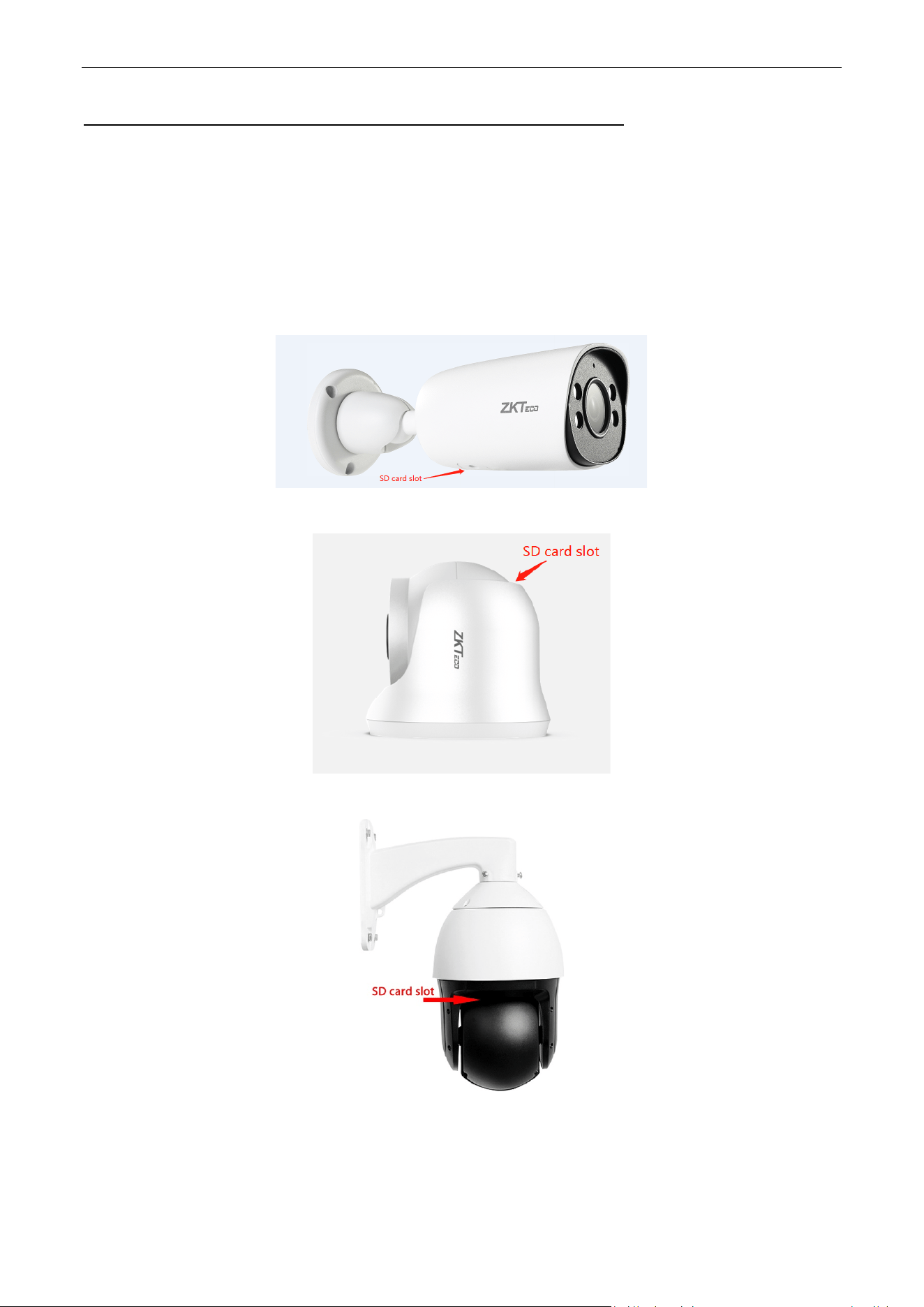
Quick Installation Guide(only SD card model)
Step 1, disassemble.
In order to ensure that the Micro-SD card will not be easily touched and loosened, the camera has designed
the Micro-SD card slot inside the camera. When installing the Micro-SD card, user needs to remove the
Micro-SD card slot cover at the bottom of camera (for the Conch model, you need to rotate the camera base
to expose the Micro-SD card slot).
Bullet Type:
Turret Type:
PTZ Type:
Biosense Series Network Camera User Manual
Page | 8 Copyright©2024 ZKTECO CO., LTD. All rights reserved.
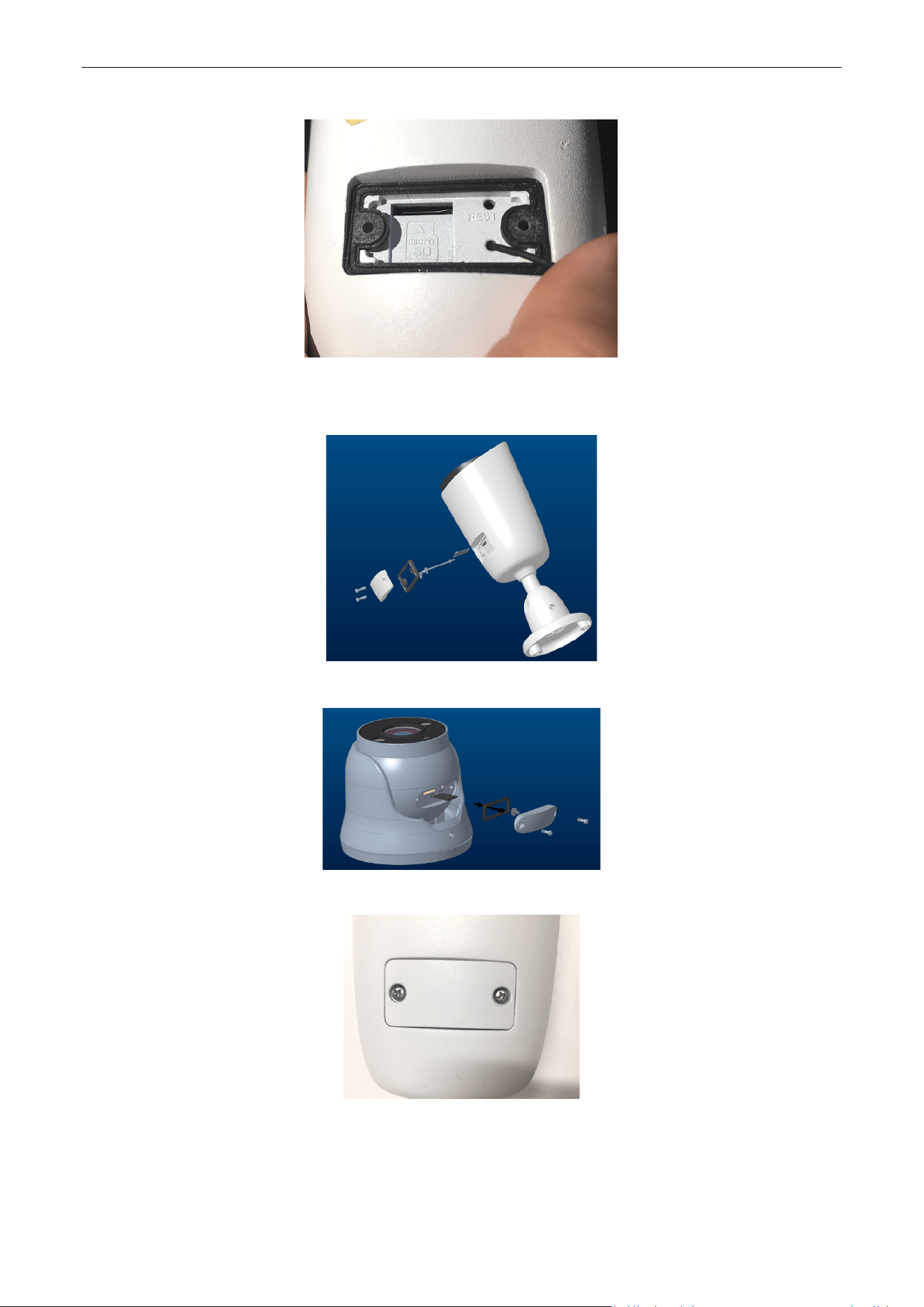
Step 2, unscrew the screw, open the cover, can see the internal Micro-SD slot.
Step 3, install the Micro-SD card in the correct direction and insert it into the slot.
Bullet Type:
Turret Type:
Step 4, close the cover and tighten the screws.
Biosense Series Network Camera User Manual
Page | 9 Copyright©2024 ZKTECO CO., LTD. All rights reserved.
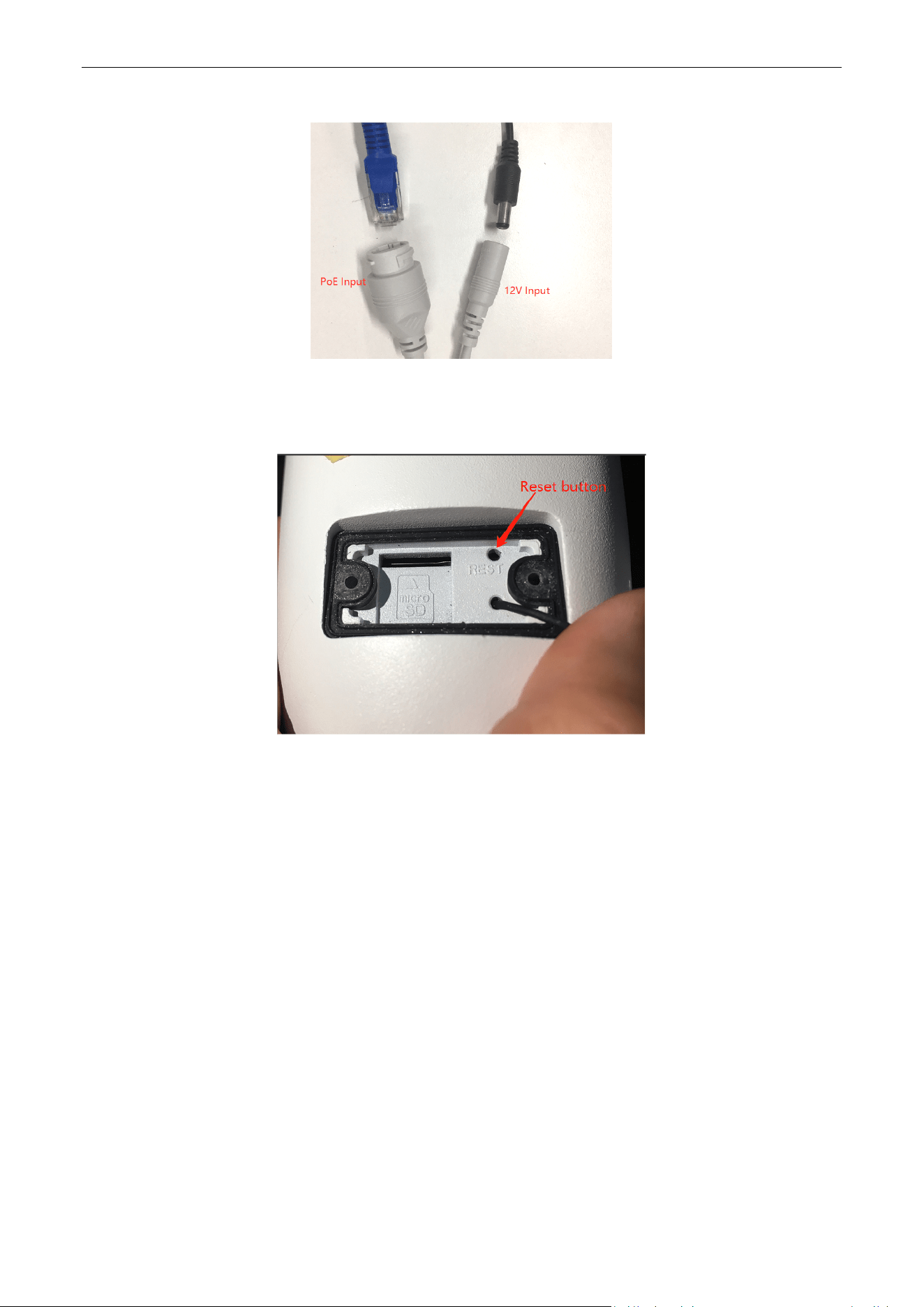
Step 5, power on the camera by PoE or 12V DC.
Note: The small round hole next to the Micro-SD card slot is the factory reset button (as picture below. In
the power-on state, press and hold the small thimble for 3 seconds, and the camera will restore the factory
default settings.
Biosense Series Network Camera User Manual
Page | 10 Copyright©2024 ZKTECO CO., LTD. All rights reserved.
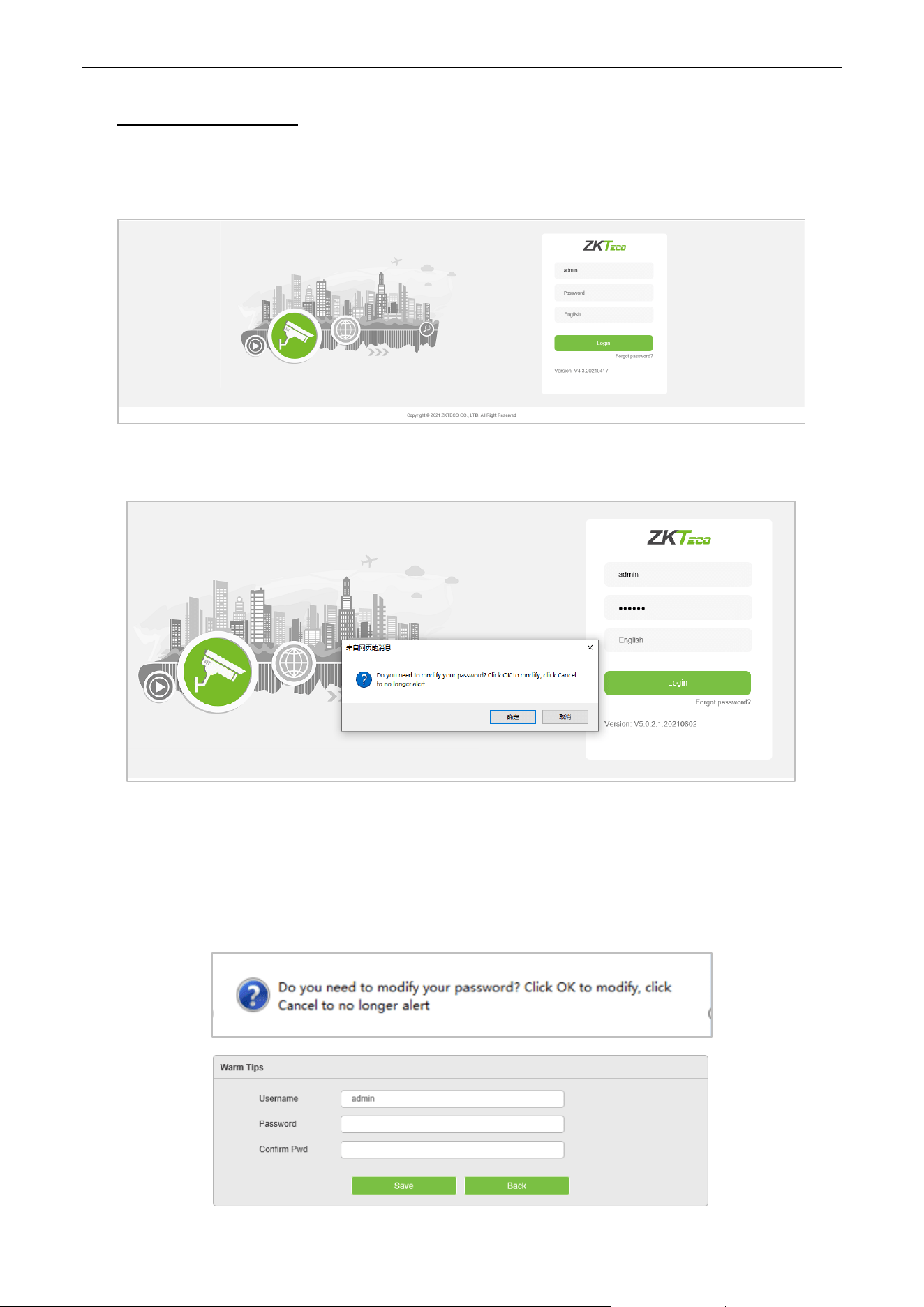
1. Login Interface
Input the IP address of the front-end device in the IE browser (the default IP address is 192.168.1.86) to access
the login interface as shown in the following picture:
Input username and password then click on “Login”, then the system will prompt a message asking whether
or not to change the password, as shown in the following figure:
User Name: admin (default setting).
Password: 123456 (default setting); users may modify the password according to the instructions.
Language: Can choose multiple languages such as English, Spanish, etc
Note: For account security, users will be prompted to reset the password when they first login.
Biosense Series Network Camera User Manual
Page | 11 Copyright©2024 ZKTECO CO., LTD. All rights reserved.
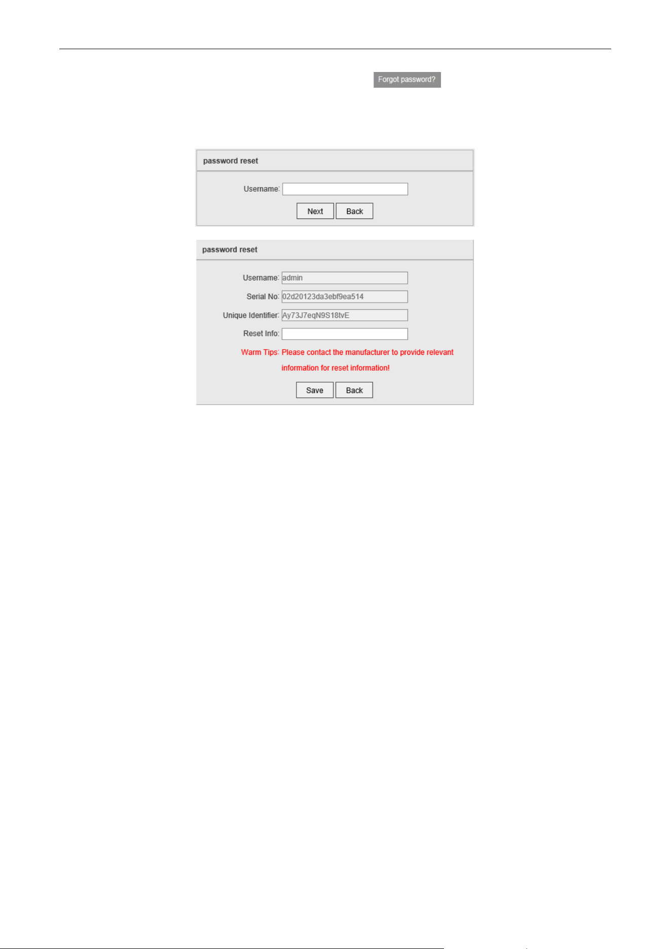
Note: if a user forgets the login password, one may click on , then the following window will
pop up. The default user name is “admin”. Click on “Next” to restore the password to factory settings
according to the prompt.
Biosense Series Network Camera User Manual
Page | 12 Copyright©2024 ZKTECO CO., LTD. All rights reserved.
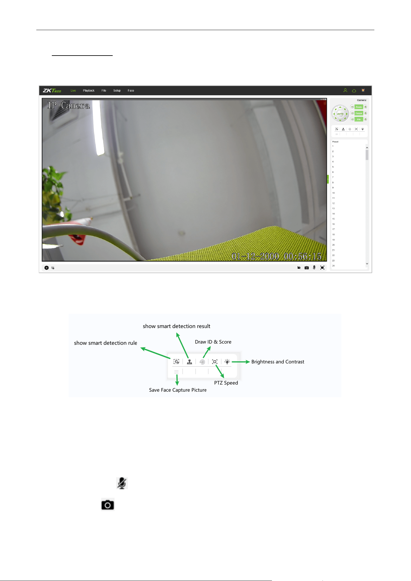
2. Live Videos
After logging in, you will enter the live video interface, as shown in the following figure.
Note: You have to insert a TF card first to access the full function display interface; otherwise, the system will
only show you the simplified version.
Show Smart Detection Rule: Show the rules of smart detection
Show Smart Detection Result: Show the result of smart detection
Save Face Capture Pictrue: Save face capture instantly
Draw ID & Score: Shows the face's randomly assigned ID and quality score
PTZ Speed: Modify the speed of the rotation of the PTZ's pan-tilt head, with 10 levels to choose from
Voice Talking: Click to enable or disable voice intercom.
Capture: Click to take screenshots. Click on the icon, the system will pop up a storage path
automatically.
Biosense Series Network Camera User Manual
Page | 13 Copyright©2024 ZKTECO CO., LTD. All rights reserved.
Full Screen: Click to display full-screen video preview.
Record: Click to allow or disallow previewing records.
Note: X indicates the function is off or disabled.
2.1. Full-screen Preview
Click on the full-screen icon in the lower right corner to get a full-screen preview. Or, you may right-
click to access (and exit) the full screen display on the preview interface.
2.2. Electronic Zoom-in
You may zoom in the preview image by scrolling the mouse wheel, as shown in the following figure:
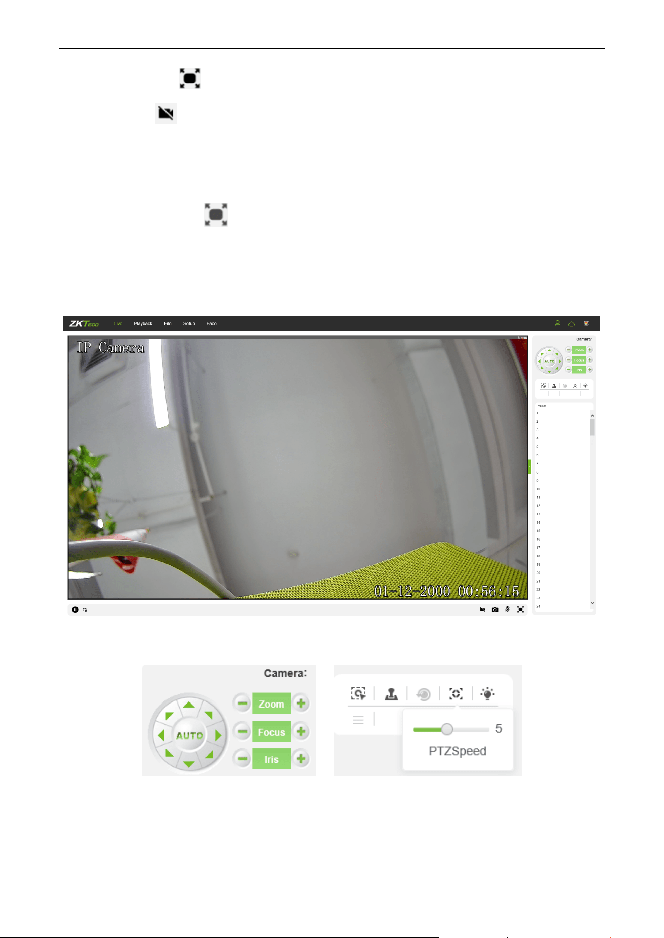
2.3. PTZ control
PTZ Control: To use eight directional keys to change the image orientation or click on the “AUTO”
button to allow auto-rotation.
Zoom In/ Out: To adjust the extent of zooming in or out.
Biosense Series Network Camera User Manual
Page | 14 Copyright©2024 ZKTECO CO., LTD. All rights reserved.
Focus: To adjust the size of focus.
Iris: To adjust the size of aperture.
PTZ Speed: Modify the speed of the rotation of the PTZ's pan-tilt head, with 10 levels to choose from.
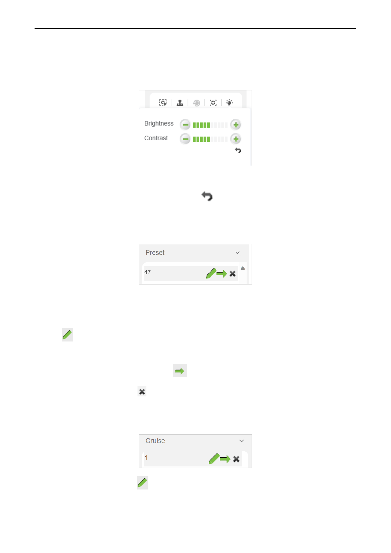
Brightness: To adjust the brightness of the screen.
Contrast: To adjust the contrast of the screen. The arrow is used to restore factory settings
2.3.1. Preset
Set a Pre-set Point: Set a pre-set point by using directional keys on the PTZ control to rotate the camera
to the desired location, then select a pre-set value from the pre-set point drop-down list, and then press
the “Set” button.
Call a Pre-set Point: Call a pre-set point by selecting a pre-set number to be called from the pre-set
point drop-down list, and then press the “Call” button.
Clear Preset Point: Click the “Clear” button to clear the corresponding preset point
2.3.2. Cruise
Set a Cruise Plan: Click the “set” button to set a cruise plan. After clicking, a setting page will
appear. Select the preset point (the corresponding preset point needs to be set in the preset point
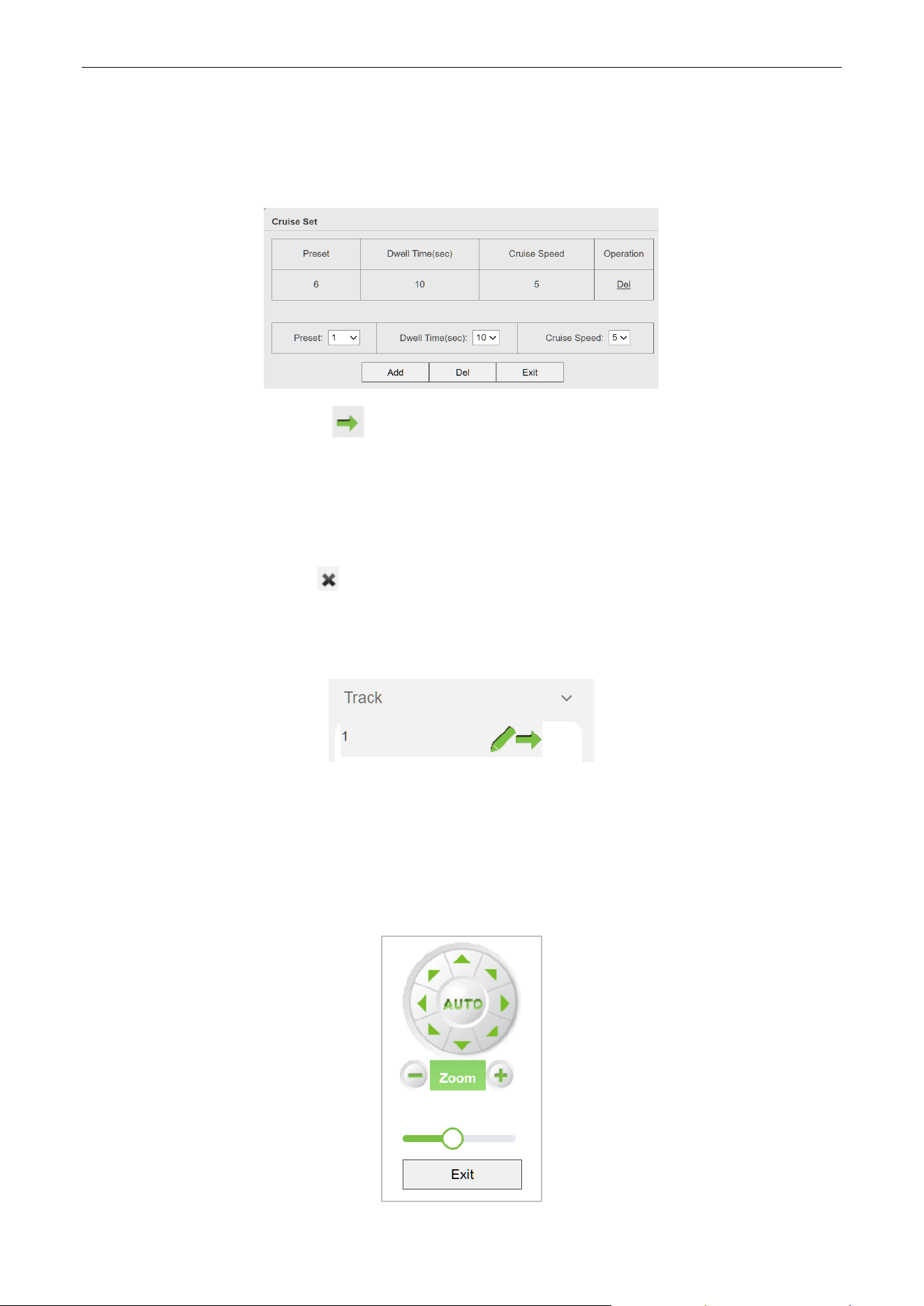
Biosense Series Network Camera User Manual
Page | 15 Copyright©2024 ZKTECO CO., LTD. All rights reserved.
module in advance), the stay time, and click the add button to add the preset point to the plan. If you
need to delete the preset point, click the del button. Click the exit button to save and exit the setting
page.
Call a Cruise Plan: Click the ”Call” button to call the preset point, and the camera will cruise
according to the set plan. Please note that during the process of going to the next preset point, the
camera cannot be interrupted by other operation commands. If you need to perform other tasks, please
execute other control commands while staying at the preset point.
Clear Cruise Plan: Click the ”Clear” button to clear the corresponding cruise plan
2.3.3. Track
Set a Track Plan: Click the set button to set the track plan. The setting page allows you to freely set the
movement trajectory and dwell time of the PTZ. Click the directional keys to rotate the PTZ directions.
Click the zoom button to zoom in and out of the lens. Drag the horizontal bar to adjust the speed of the
PTZ rotation. Click the exit button to save and exit the setting page.

Biosense Series Network Camera User Manual
Page | 16 Copyright©2024 ZKTECO CO., LTD. All rights reserved.
Call a Track Plan: Click the "Call" button to execute the corresponding track plan. Please note that
during the cruise process, performing other actions such as pan-tilt rotation will end the ongoing track
plan.
Clear Cruise Plan: Click the ”Clear” button to clear the corresponding track plan.
Biosense Series Network Camera User Manual
Page | 17 Copyright©2024 ZKTECO CO., LTD. All rights reserved.
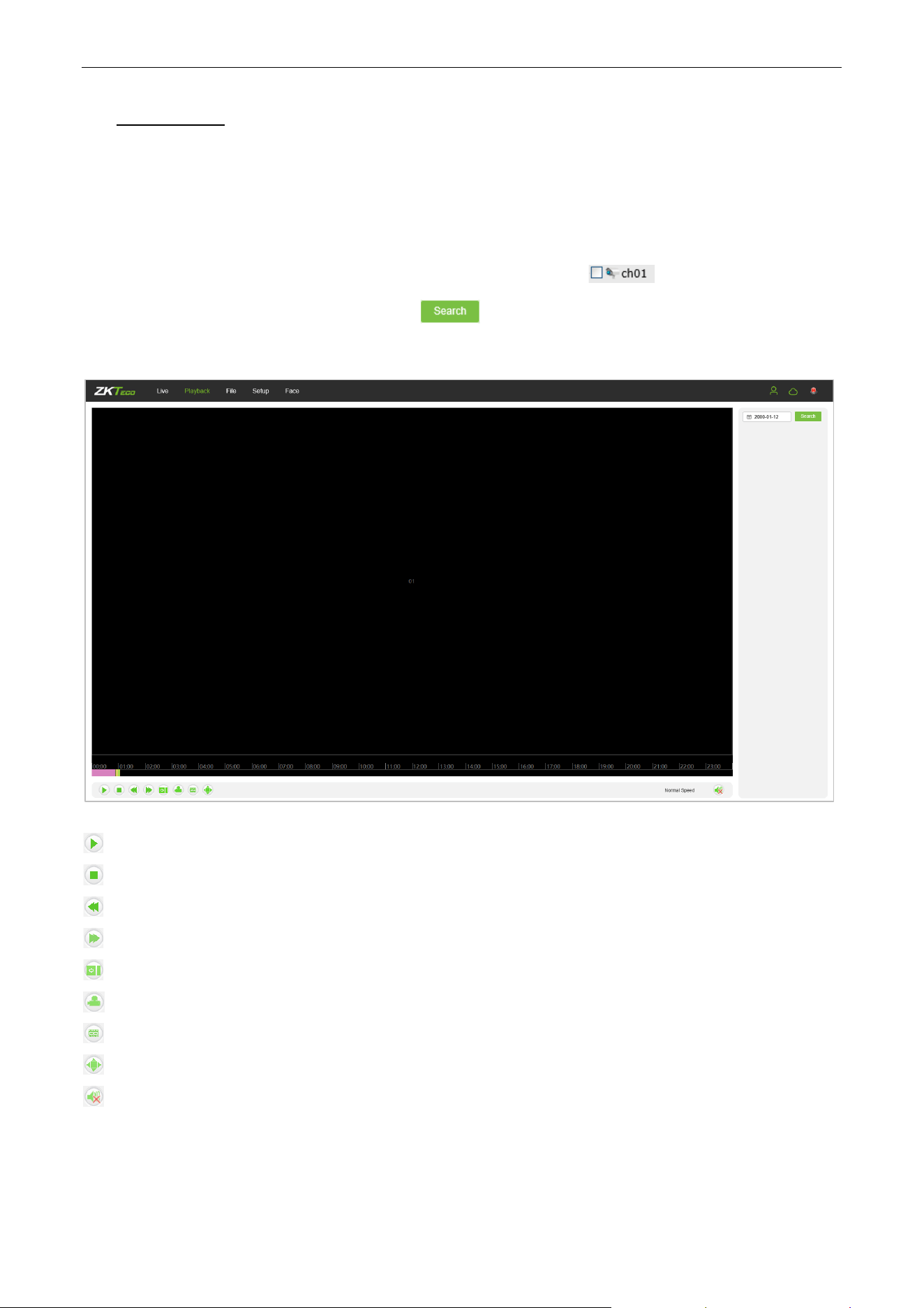
3. Playback
(The function is subject to the actual products.)
Note: You have to insert a TF card first to access the full function display interface; otherwise, the system will
only show you the simplified version.
Click on “Playback” to access the playback interface; click on the icon , select the date and time
of videos to be retrieved, then click on the icon , the system will then search for the corresponding
videos automatically, as shown in the following figure:
Start: Start the playback.
Stop: Stop the playback.
Slow: Slow down the playback speed (1/2, 1/4, 1/8, 1/16 times).
Fast: Speed up the playback speed (2, 4, 8, 16 times).
Snapshot: Take snapshots in a playback channel.
Backup: Back up videos in a playback channel.
Frame Play: Play by single frame.
Full Screen: Play videos back in full screen.
Voice: Adjust the volume of playback audio.
Double-click on the slider to play the video, or you may click the “Start” button to start playing the videos
back.
Biosense Series Network Camera User Manual
Page | 18 Copyright©2024 ZKTECO CO., LTD. All rights reserved.
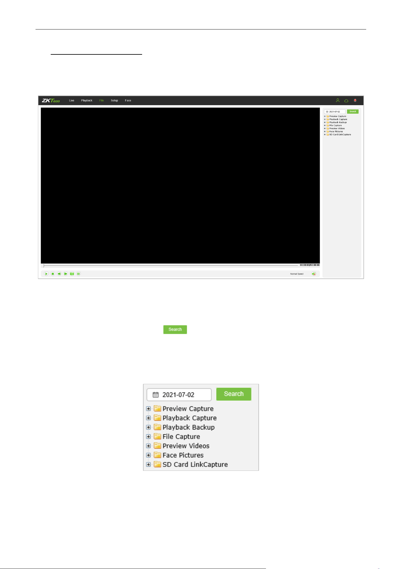
4. File Management
Note: You have to insert a TF card first to access the full function display interface; otherwise, the system will
only show you the simplified version.
Face Picture: Capture image after face verification successfully
4.1. Search
Input a concrete time, and click on the button, the lower part of the screen will display the
searched images and videos. You may double-click on the searched results to access files you need.
Note: You may modify the storage paths of the selected videos or images. A short description will
be given below. For more details, please go to Setup → Local Settings.
4.2. Preview Capture
To review captured images from video preview; you may search for and double click to obtain images you
need.

Biosense Series Network Camera User Manual
Page | 19 Copyright©2024 ZKTECO CO., LTD. All rights reserved.
4.3. Playback Capture
To review captured images from video playback; you may search for and double click to obtain images you need.
4.4. Playback Backup
To retrieve video files; you may search for and view videos files.
4.5. File Capture
To review captured images from the file management interface; you may search for and double click to
obtain the images you need.
4.6. Preview Videos
To preview videos recorded; you may search for and double click to access the videos you need.
4.7. SD Card Link Capture
To review snapshots from a SD card; you may search for and double click to access the videos you need.
4.8. Backup Video Play
Start: Click on the button to play a selected backup video.
Stop: Click on the button to stop playing the video.
Slow: Click on the button to slowly play the video back.
Fast: Click on the button to fast-forward the video.
Frame: Click on the button to play the video by frame.
Capture: Click on the button to take a snapshot of the display during playback.
Voice: Clik on the button to turn sound on or off during playback.
Biosense Series Network Camera User Manual
Page | 20 Copyright©2024 ZKTECO CO., LTD. All rights reserved.
5. Parameter
Note: You have to insert a TF card first to access the full function display interface; otherwise, the system will
only show you the simplified version.
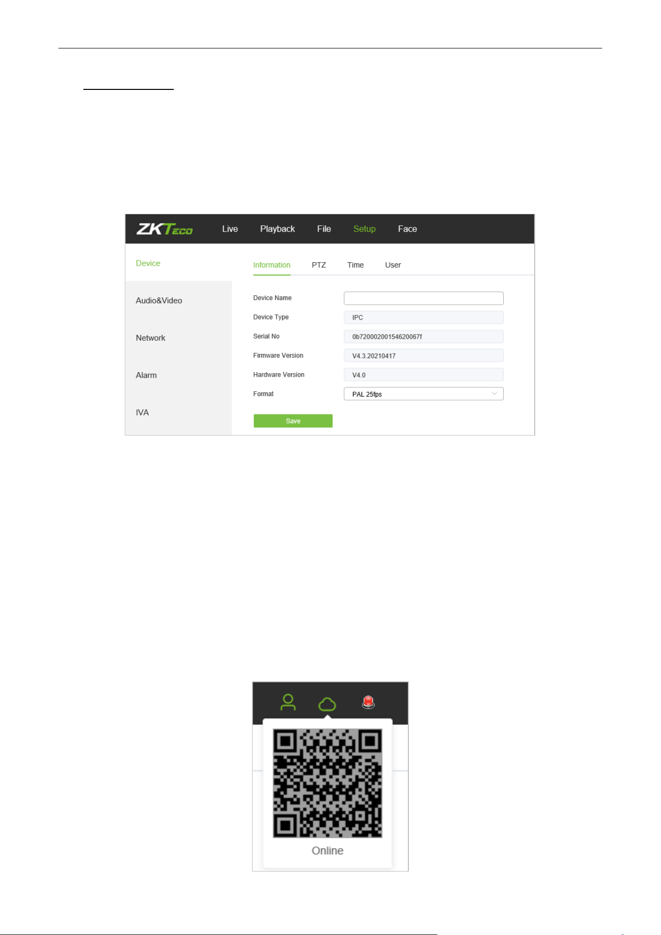
5.1. Device Information
Below is the Device Information interface of the IP camera:
Device Name: Edit the camera name.
Device Type: Display the device type.
Serial No: Display the product serial number.
Firmware Version: Display information about the firmware version.
Hardware Version: Display the version number of the hardware.
Format: Select between PAL and NTSC image scanning system.
After completing all parameters settings, click on “Save”, then the settings will take effect immediately.
5.2. QR Code
IPC with P2P function can be remotely connected to the mobile APP by scanning the QR Code on this page.
Biosense Series Network Camera User Manual
Page | 21 Copyright©2024 ZKTECO CO., LTD. All rights reserved.
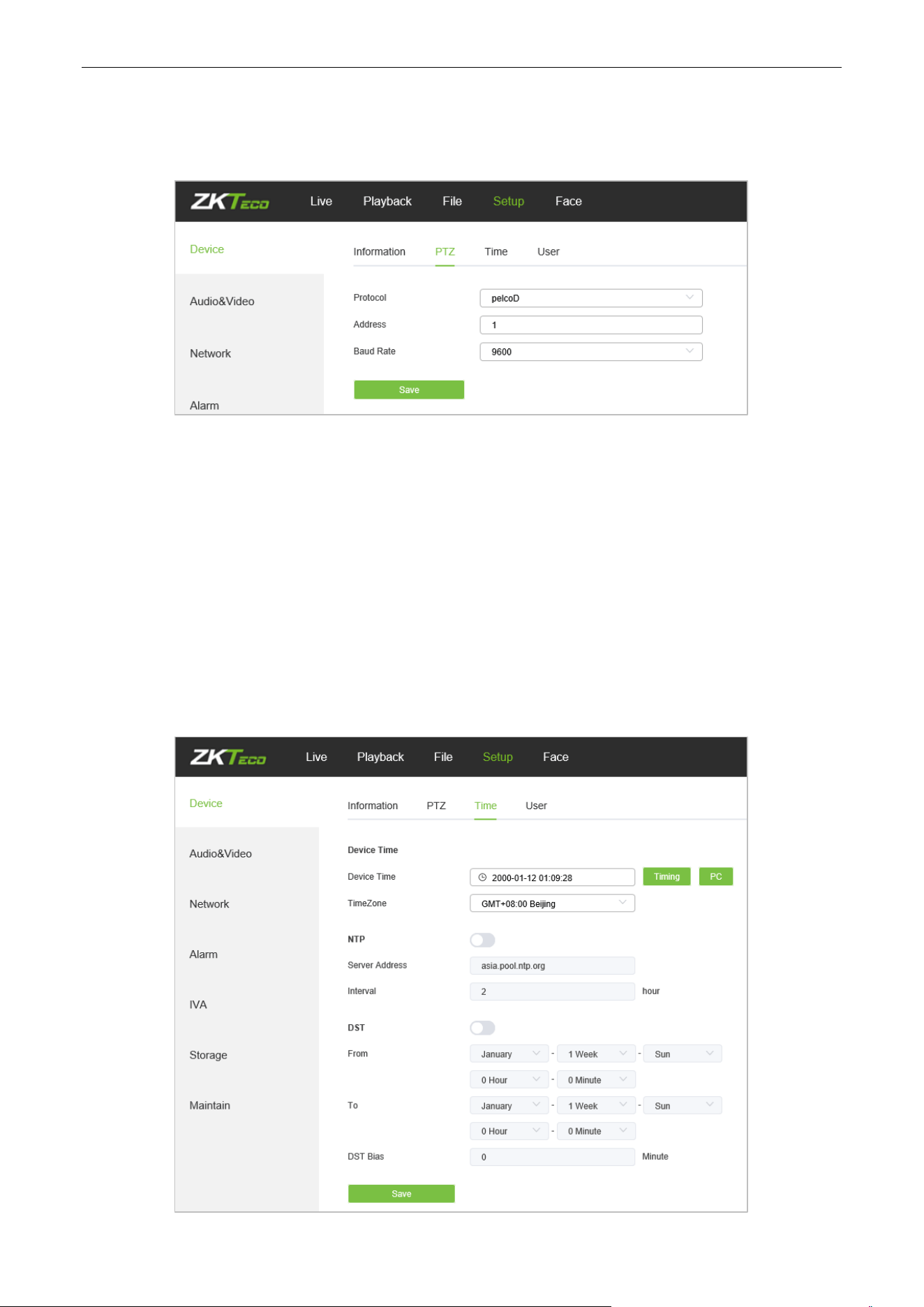
5.3. PTZ Settings
Below is the PTZ Settings interface of the IP camera:
Protocol: multiple protocols available.
Address: 0-255 address codes available.
Baud Rate: diverse baud available
Operation Method: Login the PTZ camera web interface, “Setup” ==> “Device” ==> PTZ, set a protocol
and baud rate. After completing all parameters settings, click on “Save”, then the settings will take effect
immediately.
5.4. Time Settings
Below is the Time Settings interface of the IP camera:
Biosense Series Network Camera User Manual
Page | 22 Copyright©2024 ZKTECO CO., LTD. All rights reserved.
Device Time: Set and display the current time of the camera.
Time Zone: Different time zones are available.
Enable NTP: Click to enable or disable NTP.
Server Address: Input the IP address of the NTP server.
Interval: Input the interval of time.
After completing all parameters settings, click on “Save”, then the settings will take effect immediately.
Enable DST: Daylight saving time
DSTBias: the length of the additional offset after starting daylight saving time (0-720 points)
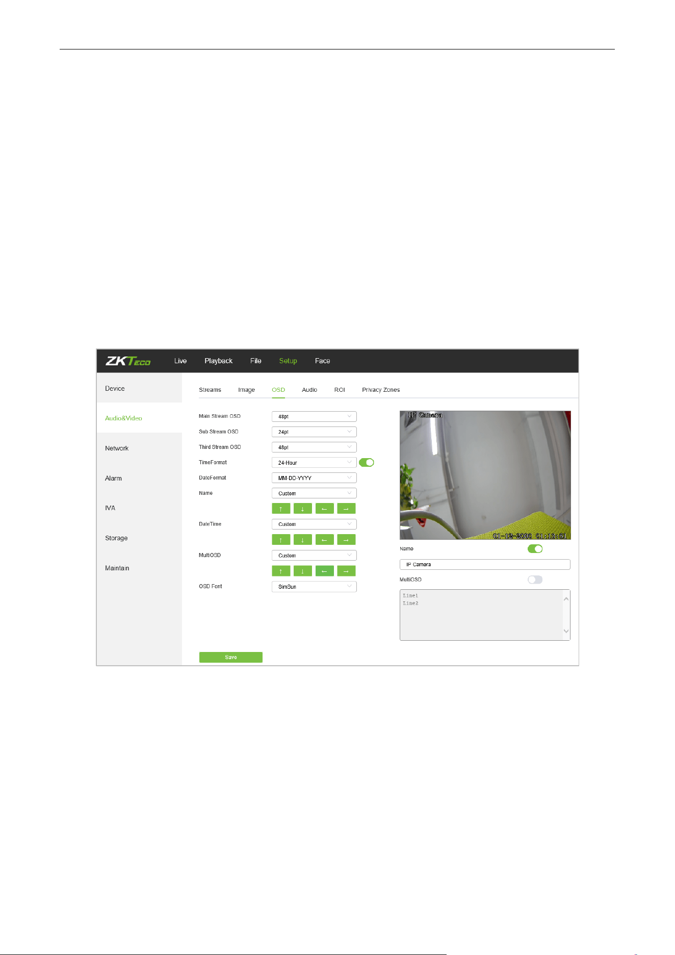
5.5. Display Settings
Below is the Display Settings interface of the IP camera:
Name: Modify the appointed channel name.
Main Stream OSD: Modify the appointed font of the OSD in main stream preview channel.
Sub Stream OSD: Modify the appointed font of the OSD in sub stream preview channel.
Three Stream OSD: Modify the appointed font of the OSD in three stream preview channel.
Multi OSD: Add a multi-user-defined OSD, which you may choose whether to display.
Time Format: Select different time format for the appointed channel.
Date Format: Select different date format for the appointed channel.
Name: Set the location of the title for the appointed channel.
Date Time: Set the location of the date for the appointed channel.
Biosense Series Network Camera User Manual
Page | 23 Copyright©2024 ZKTECO CO., LTD. All rights reserved.
Multi OSD: Set the position of multi OSD.
OSD Color: Set the color of the OSD font.
OSD Font: Select OSD font.
After completing all parameters settings, click on “Save”, then the settings will take effect immediately.
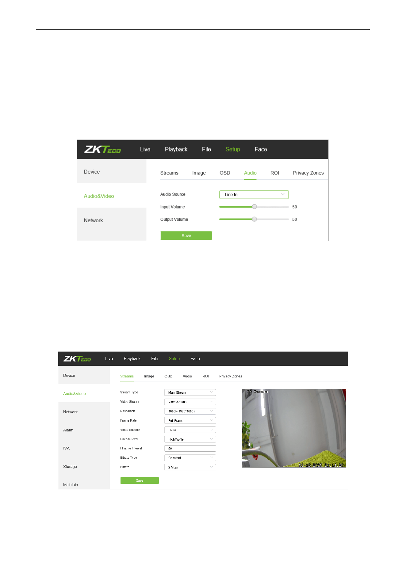
5.6. Audio Settings
Below is the Audio Settings interface of the IP camera:
Audio Source: Select the audio input mode between Line In and Mic In.
Input Volume: Set the input volume which ranges from 0 to 100; the default settings is 50.
Output Volume: Set the output volume which ranges from 0 to 100; the default settings is 50.
After completing all parameters settings, click on “Save”, then the settings will take effect immediately.
5.7. Streams
Below is the Streams setting interface of the IP camera:
Stream Type: Main stream/ Sub-stream/Third Stream
Video Stream: Video&Audio/ Video
Biosense Series Network Camera User Manual
Page | 24 Copyright©2024 ZKTECO CO., LTD. All rights reserved.
Resolution: Several resolutions available (Note: Based on the defaulted resolution of different
products).
Frame Rate: Select different frame rates from the drop-down list; the default settings is “Full Frame”.
Video Encode : H.264/ H.265.
Encode level: Main profile/ Baseline/ High Profile.
I Frame Interval: Set the interval size of I frame.
Bitrate Type: Constant/ variable.
Bitrate: Set different bitrates for different channels (Note: Based on the defaulted resolution of
different products)
After completing all parameters settings, click on “Save”, then the settings will take effect immediately.
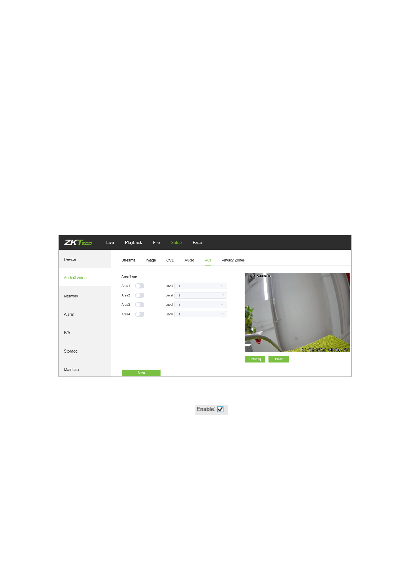
5.8. ROI Settings
Below is the ROI Settings interface of the IP camera:
ROI Settings: On the preview window, hold the left mouse button and drag to set the ROI area. There
are a total of four ROI areas available. Click on to set the corresponding ROI region coding
level; the higher level the coding, the stronger the ROI region encoding.
After completing all parameters settings, click on “Save”, then the settings will take effect immediately.
Biosense Series Network Camera User Manual
Page | 25 Copyright©2024 ZKTECO CO., LTD. All rights reserved.
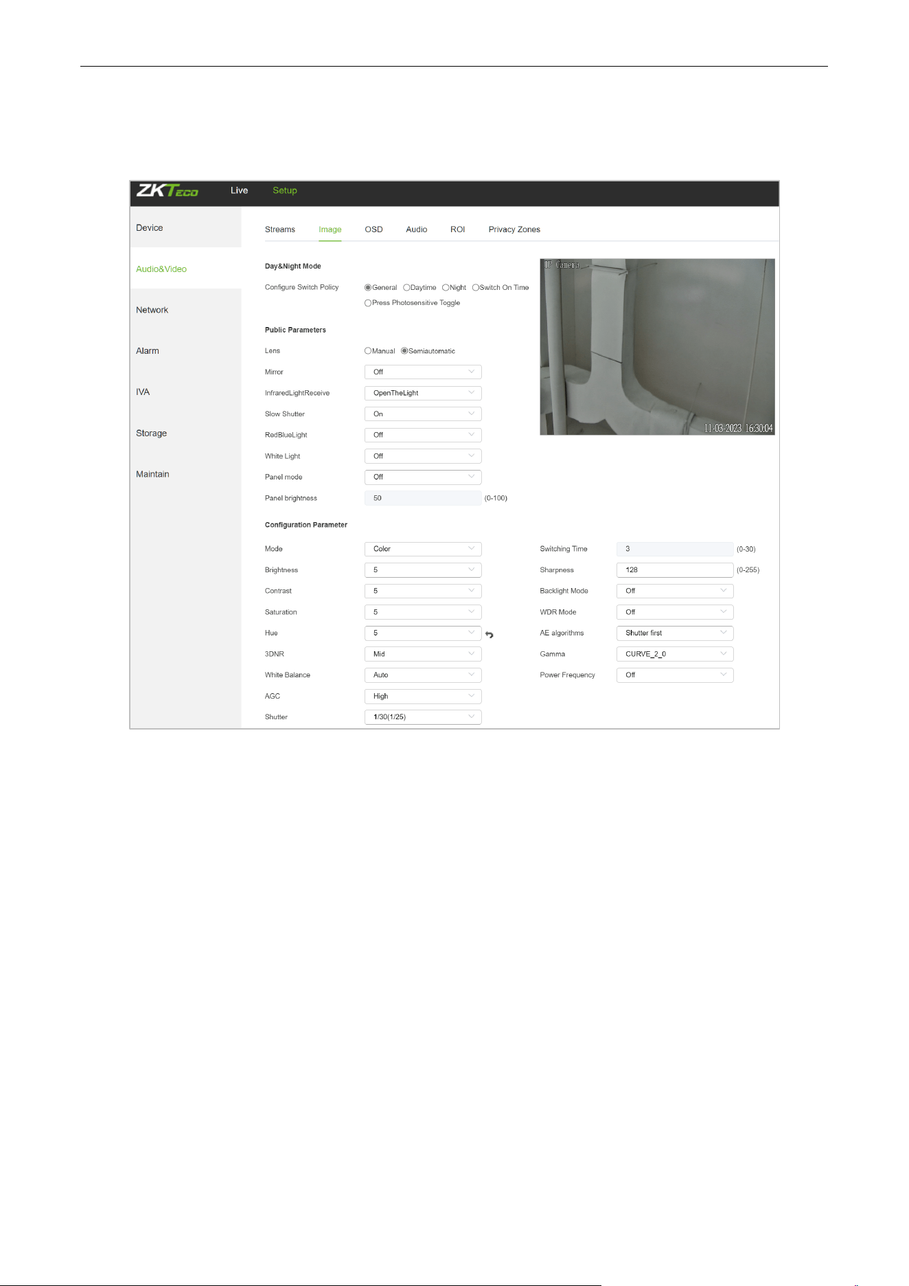
5.9. Image Parameters
Below is the Image Parameters interface of the IP camera:
Day/Night Mode: Outside Trigger/ Auto/ Color/ Black White. The default setting of non-infrared IP
cameras is “Auto”, and the default setting of infrared IP cameras is “Outside Trigger”. Users may set the
Day/Night mode as needed according to the type of the IP camera and the actual application
environment.
Public
Parameters (Some parameters only support models that are displayed):
Lens: Adjust the focus mode of the lens. In the semi-automatic mode, the lens will automatically focus.
In the manual mode, the lens will not automatically focus.After adjusting the lens magnification, you
need to manually focus.
Mirror: Off Horizontal Mirror/ Vertical Mirror/ 180° Rotation/90° Rotation/270° Rotation ; the
default setting is “Off”.
InfraredLightReceive: When enabled, it will automatically adjust the infrared light brightness to adapt
to the ambient brightness.
Slow Shutter: Off/On; the default setting is “Off”.
RedBlueLight: When enabled, the red and blue lights will light up when the trigger conditions are met.

Biosense Series Network Camera User Manual
Page | 26 Copyright©2024 ZKTECO CO., LTD. All rights reserved.
White Light: When turned on, the white light will light up when the trigger conditions are met.
Panel mode: Used to control the infrared lamp on/off/brightness adjustment. After selecting auto, you
can select the corresponding infrared lamp brightness in Panel Brightness.
Configuration Parameter:
Switching Time: Day & Night switch delay time which ranges from 0-30s; the default setting is 3s.
Day/Night: ranges from 0 to 255. Users may set the value as needed; the default setting is 20.
Night/Day: ranges from 0 to 255. Users may set the value as needed; the default setting is 35.
Color Mode: Normal/ Bright/ Nature; the default setting is “Normal”
WDR Mode: Off/ BLC/ WDR; the default setting is “Off”.
3DNR: Off/ Low/ Mid/ Mid-High/ High; the default setting is “Low”.
Sharpness: ranges from 0 to 255; the default setting is 128.
Defogging: Off/ Low/ Mid/ High; the default setting is “Off”.
White Balance: Users may set the value of white balance. “Auto white balance” is suitable for normal
light environment. Users may adjust the white balance mode from the drop-down list.
Exposure Control: Auto/ manual; the default setting is “Auto”.
AE algorithms: Shutter first/ gain first; the default setting is “Shutter first”.
AGC: AGC can be set when the camera is automatically exposed. You may select from Low/ Mid-Low/
Mid/ Mid-High/ High; the default settings is “Mid-High”. The larger the “Auto Gain” value, the better the
sensitivity under low illumination, and the more obvious the noise will be.
Shutter: You may set manual exposure; the value ranges from 1/25(30) to 1/10000.
Aperture: Depending on the type of IPC lens, the aperture can be divided into manual aperture and
auto aperture (Note: based on the defaulted aperture of different products); and the lens can be divided
into manual focus and vari-focus.
Gamma: A total of four modules: CURVE_1_6, CURVE_1_8, CURVE_2_0, CsURVE_2_2; the default
setting is CURVE_2_0.
Power Frequency: There are three options: off, 50hz, 60hz; the default setting is “off”.
Light board control mode: There are three LED board control modes: off, manual, auto; the default
setting is “auto”.
Off mode: The IR LED will not be turned on.
Manual mode: The brightness of the LED board can be adjusted by manually changing the related
parameters, and the value ranges from 1 to 100. The larger the parameter value, the brighter the IR LED.
Auto mode: The brightness of the LED board can be adjusted automatically.
Brightness: The brightness of the LED board can be set when the LED board control is under “Manual”
mode. The value ranges from 1 to 100.
Biosense Series Network Camera User Manual
Page | 27 Copyright©2024 ZKTECO CO., LTD. All rights reserved.
Target Brightness: Adjust the target brightness
AE algorithms: Priority selection of adjusting the brightness
AGC:Improve the image signal to amplification the brightness, which will amplification the image noise
Model: Brightness adjustment mode of InfraredLight
Brightness: Manually set the brightness of the InfraredLight
After completing all parameters settings, click on “Save”, then the settings will take effect immediately.
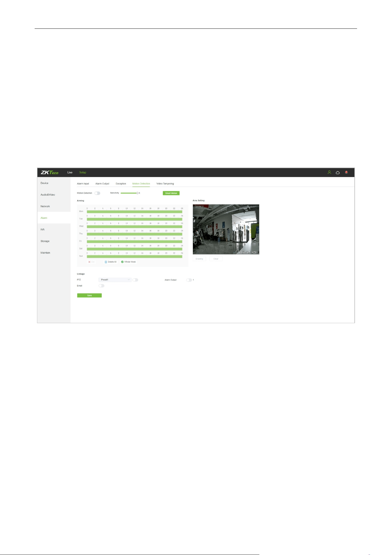
5.10. Motion Detection
Below is the Motion Detection setting interface of the IP camera:
Enable: Select whether to enable the Motion Detection function.
Sensitivity: The higher the sensitivity, the more obvious the motion detective effect will be.
Week: The Detection time can be set from Monday to Sunday.
Arming Schedule: Set up an arming period; you may set up to 8 time periods for a day.
Area Setting: On the “Area Setting" preview interface, left-click and drag the mouse to set the area to
be monitored.
Clear: Click on “Clear” to clear the current controlled areas.
Email: Click on “Email”. Once an alarm is triggered, an email will be automatically sent to the appointed
mailbox.
Snap: Click on “Snap”. Once an alarm is triggered, a signal will instantly be sent to the camera to take a
snapshot and store it in the TF card.
Record: Click on “Record”. Once an alarm is triggered, a signal will instantly be sent to the camera to
record a video and store it in the TF card.
Biosense Series Network Camera User Manual
Page | 28 Copyright©2024 ZKTECO CO., LTD. All rights reserved.
Alarm Output: There should be an active alarm device inserted into the IPC alarm output port. Once
an alarm event is triggered, the IPC and alarm device will set off the alarm.
PTZ: Enable or disable PTZ function.
Preset: When motion detection triggers an alarm, the alarm will link with the preset point.
Snap Interval: Set the time intervals for taking snapshots.
Snap Number: Set the number of snapshots taken each time.
After completing all parameters settings, click on “Save”, then the settings will take effect immediately.
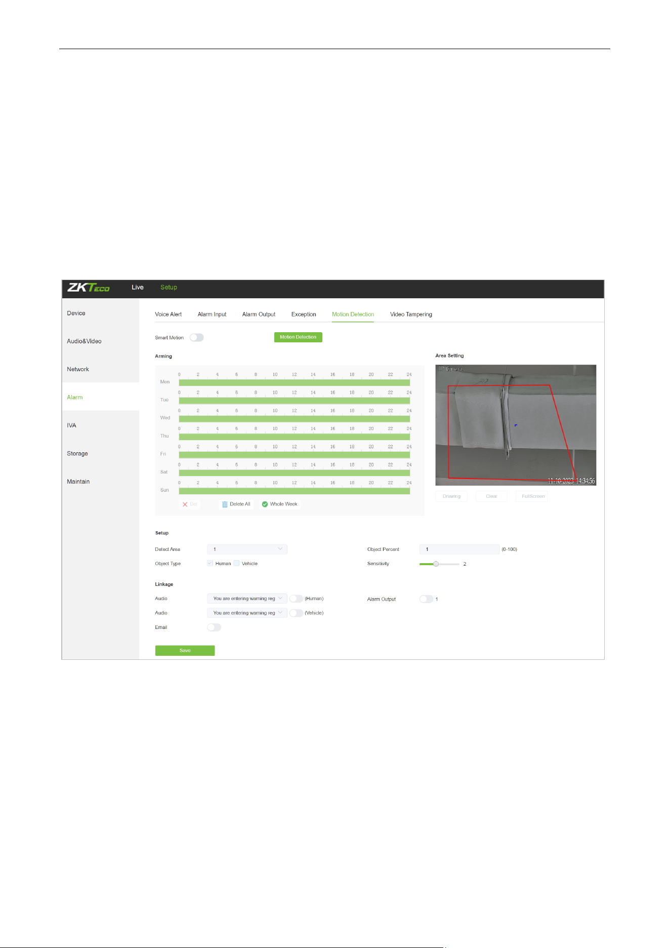
5.10.1. Smart Motion
Enable: Select whether to enable the Motion Detection function.
Week: The Detection time can be set from Monday to Sunday.
Arming Schedule: Set up an arming period; you may set up to 8 time periods for a day.
Area Setting: On the “Area Setting" preview interface, left-click and drag the mouse to set the area to
be monitored.
Clear: Click on “Clear” to clear the current controlled areas.
Detect Area: Add controlled zones (max. 4).
Object Percent: Sets the size of the object that triggers the alert. If objects smaller than the preset value,
such as mosquitoes and leaves, enter the monitoring area, the alarm will not be triggered.
Biosense Series Network Camera User Manual
Page | 29 Copyright©2024 ZKTECO CO., LTD. All rights reserved.
Object Type: Set the detection object to be human or vehicle, and an alarm will be triggered when the
object detected in the area is the set value.
Sensitivity: The higher the sensitivity, the more obvious the motion detective effect will be.
Email: Click on “Email”. Once an alarm is triggered, an email will be automatically sent to the appointed
mailbox.
Alarm Output: There should be an active alarm device inserted into the IPC alarm output port. Once
an alarm event is triggered, the IPC and alarm device will set off the alarm.
PTZ: Enable or disable PTZ function.
Preset: When motion detection triggers an alarm, the alarm will link with the preset point.
Snap: Click on “Snap”. Once an alarm is triggered, a signal will instantly be sent to the camera to take a
snapshot and store it in the TF card.
Record: Click on “Record”. Once an alarm is triggered, a signal will instantly be sent to the camera to
record a video and store it in the TF card.
Audio: Turn on the corresponding human/vehicle option to play the selected voice when the alarm is
triggered. For voice settings, please refer to Section 5.37.
After completing all parameters settings, click on “Save”, then the settings will take effect immediately.
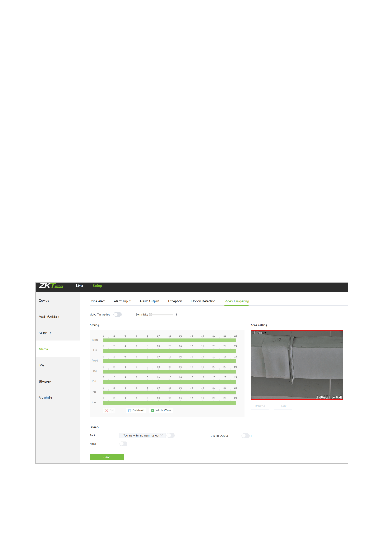
5.11. Video Tampering
Below is the Video Tampering setting interface of the IP camera:
Enable: Select whether to enable the video tampering function.
Sensitivity: The higher the sensitivity, the easier to trigger the video tampering alarm.
Biosense Series Network Camera User Manual
Page | 30 Copyright©2024 ZKTECO CO., LTD. All rights reserved.
Week: The protection time can be set from Monday to Sunday.
Arming Schedule: Set up a protection period; you may set up to 8 time periods for a day.
Area Setting: On the “Area Setting" preview interface, left-click and drag the mouse to set the area to
be monitored.
Clear: Click on “Clear” to clear the current controlled areas.
Email: Click on “Email”. Once an alarm is triggered, an email will be automatically sent to the appointed
mailbox.
Snap: Click on “Snap”. Once an alarm is triggered, a signal will instantly be sent to the camera to take a
snapshot and store it in the TF card.
Record: Click on “Record”. Once an alarm is triggered, a signal will instantly be sent to the camera to
record a video and store it in the TF card.
Alarm Output: There should be an active alarm device inserted into the IPC alarm output port. Once
an alarm event is triggered, the IPC and alarm device will set off the alarm.
PTZ: Enable or disable PTZ function.
Preset: When video tampering triggers an alarm, the alarm will link with the preset points.
Snap Interval: Set the time intervals for taking snapshots.
Snap Number: Set the number of snapshots taken each time.
Audio: Turn on the corresponding human/vehicle option to play the selected voice when the alarm is
triggered. For voice settings, please refer to Section 5.37.
After completing all parameters settings, click on “Save”, then the settings will take effect immediately.
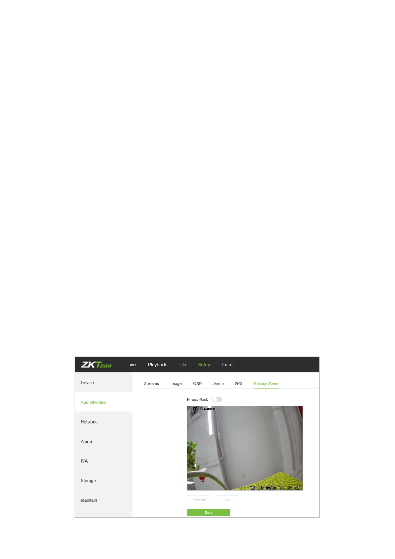
5.12. Privacy Mask
Below is the Privacy Mask setting interface of the IP camera:
Biosense Series Network Camera User Manual
Page | 31 Copyright©2024 ZKTECO CO., LTD. All rights reserved.
Enable: Enable or disable the Privacy Mask feature.
Area Settings: Left-click and drag the mouse on the Area Settings preview interface drawing to set the
mask area.
Clear: Click on “Clear” to delete the current controlled area.
After completing all parameters settings, click on “Save”, then the settings will take effect immediately.
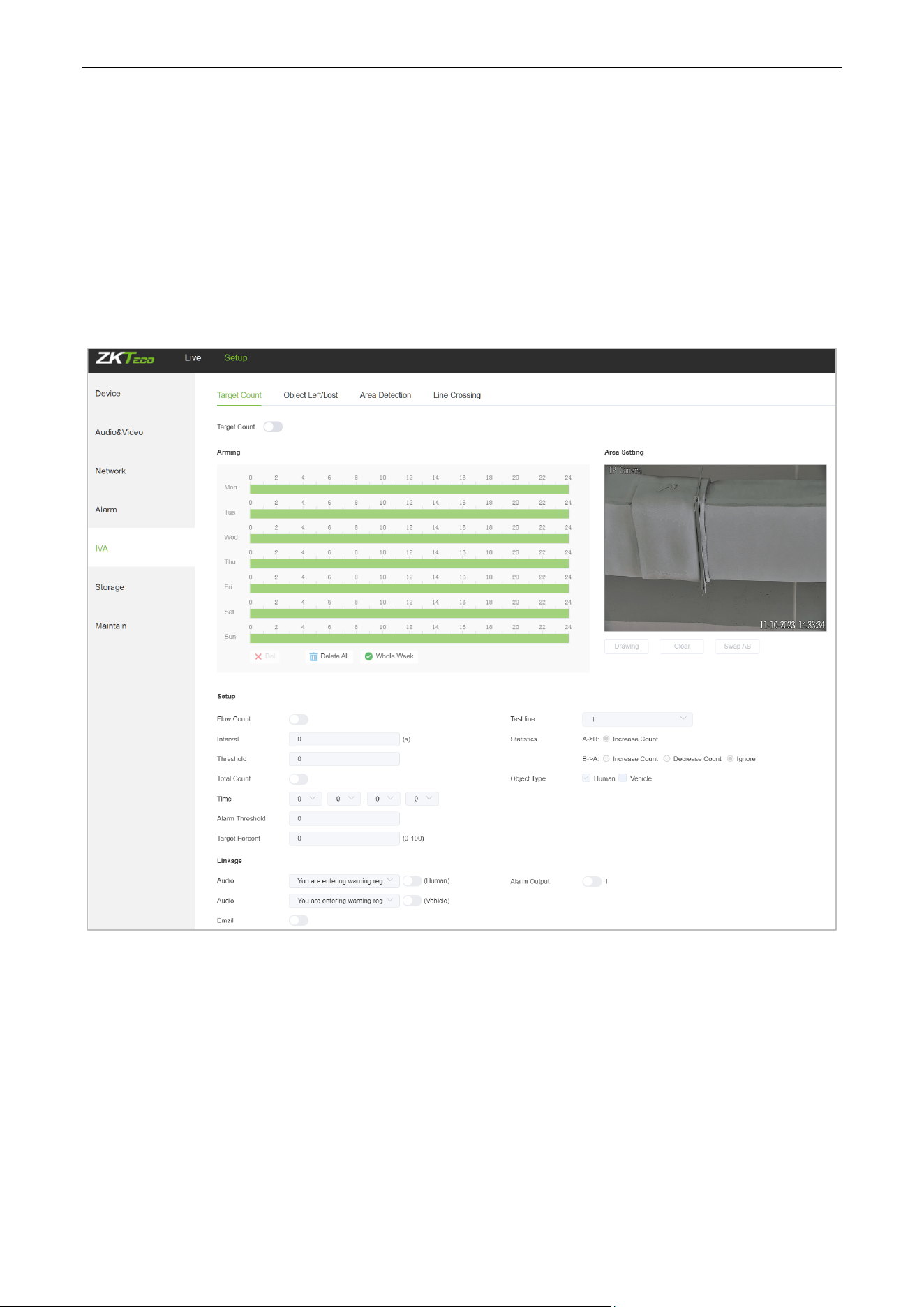
5.13. Target Counting
Below is the Target Count setting interface of the IP camera:
Enable: Enable or disable the target counting function.
Arming Schedule: Arm schedule can be set from Monday to Sunday.
Area Setting: Click on “Drawing”, then left-click and drag the mouse button to set the test line on the
Area Settings preview interface. Click on “Stopping” to complete the setting, then the system will count
the number of targets passing through the line.
Clear: Click on “Clear” to delete all the test lines.
Swap AB: Click on “Swap AB" to exchange position between A and B.
Test Line: Add test lines (max. 4 test lines).

Biosense Series Network Camera User Manual
Page | 32 Copyright©2024 ZKTECO CO., LTD. All rights reserved.
Statistics: Set the test lines for targets passing through. There are two statistical methods: A→B and B
→A.A→B will increase the count by default, and B→A can set to increase the count, decrease the count
or ignore.
Object Type: Set the detection object to be human or vehicle, and an alarm will be triggered when the
object detected in the area is the set value.
Flow Count: Enable or disable the Flow Counter feature.
Interval: Set the counting time interval. When the counting time exceeds the time interval set, the flow
counter will reset and enter next counting period automatically.
Threshold: Set the upper count limit. When the value exceeds the set value, the system will
automatically trigger the alarm.
Total Count: Enable or disable the Total Counter function.
Time Period: Set the effective time period for the day’s total counter.
Alarm Threshold: Set the upper limit of the total flow on a day. When the value exceeds the set value,
the system will automatically trigger the alarm.
Target Percent: Sets the size of the object that triggers the alert. If objects smaller than the preset value,
such as mosquitoes and leaves, enter the monitoring area, the alarm will not be triggered.
Email: Click on “Email”. Once an alarm is triggered, an email will be automatically sent to the appointed
mailbox.
Snap: Click on “Snap”. Once an alarm is triggered, a signal will instantly be sent to the camera to take a
snapshot and store it in the TF card.
Record: Click on “Record”. Once an alarm is triggered, a signal will instantly be sent to the camera to
record a video and store it in the TF card (for cameras which support TF cards only).
Alarm Output: There should be an active alarm device inserted into the IPC alarm output port. Once
an alarm event is triggered, the IPC and alarm device will set off the alarm.
PTZ: Enable or disable PTZ function.
Preset: When target counting triggers an alarm, it will link the pre-sets.
Snap Interval: Set the time intervals for taking snapshots.
Snap Number: Set the number of snapshots taken each time.
Audio: Turn on the corresponding human/vehicle option to play the selected voice when the alarm is
triggered. For voice settings, please refer to Section 5.37.
After completing all parameters settings, click on “Save”, then the settings will take effect immediately.
Biosense Series Network Camera User Manual
Page | 33 Copyright©2024 ZKTECO CO., LTD. All rights reserved.
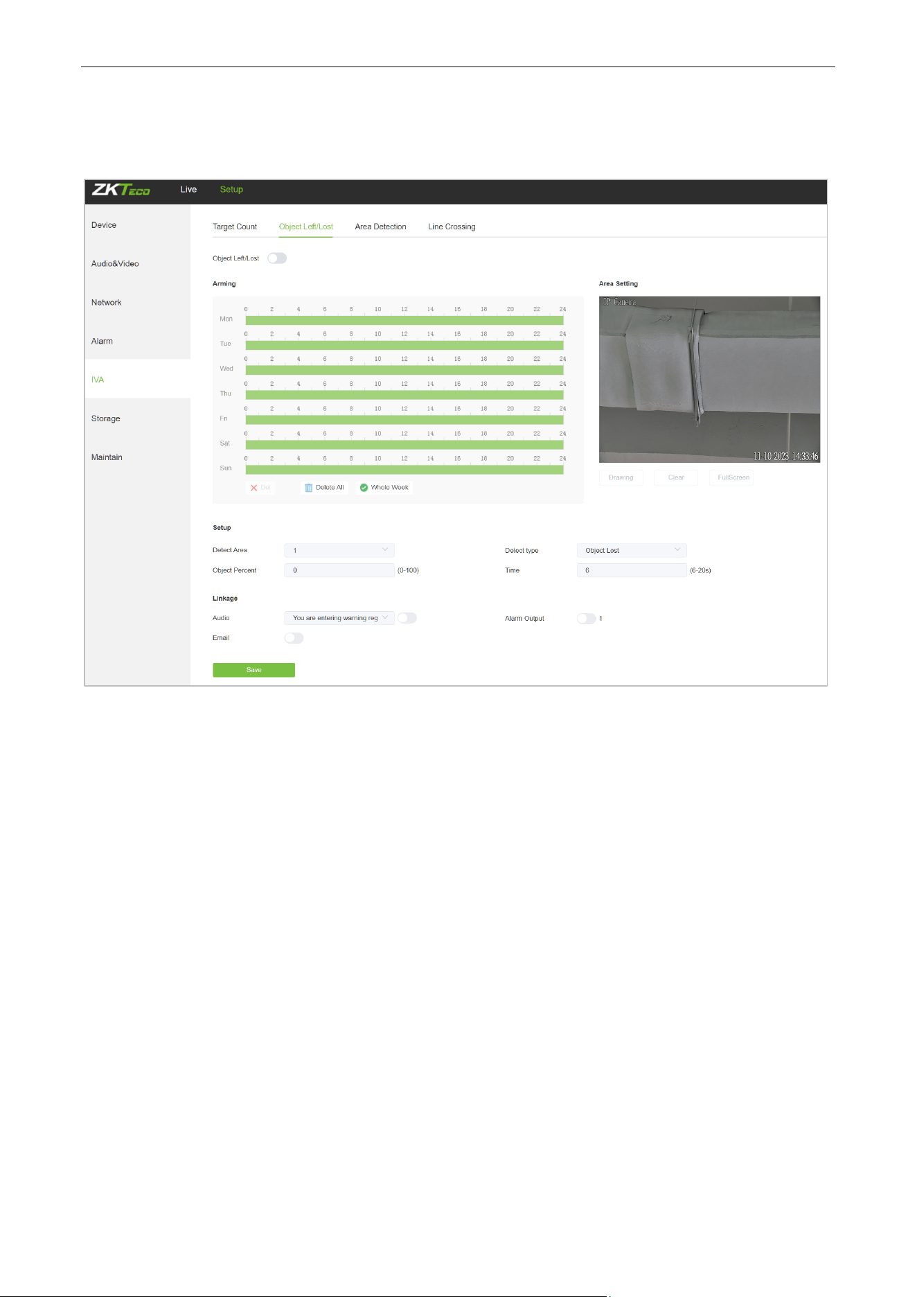
5.14. Object Left / Lost
Below is the Object Left/Lost setting interface of the IP camera:
Enable: Enable or disable the object detection function.
Arming Schedule: Arming schedule can be set from Monday to Sunday.
Area Setting: Click on “Drawing”, then left-click and drag the mouse button to set the detect zone on
the Area Settings preview interface. Click on” Stopping” to complete the setting, then the system will
detect, and monitor objects appeared in the selected area.
Clear: Click on “Clear” to delete all zones.
Detect Area: Add controlled zones (max. 4).
Detect Type: Set the object detection type. There are three detection types, all of them are able to
trigger the alarm. “Item lost” represents that the camera will trigger the alarm once it detects that an
item originally in the monitored area is missing; “Item left” represents that the camera will trigger the
alarm once it detects a new item in the detection area; “Item lost or left” represents that the camera will
trigger the alarm once it detects that an item is missing and/or a new item in the controlled area.
Object Percent: Sets the size of the object that triggers the alert. If objects smaller than the preset value,
such as mosquitoes and leaves, enter the monitoring area, the alarm will not be triggered.
Detect Time: Set the upper limit of item lost and item left. When it exceeds the set value, the system
Biosense Series Network Camera User Manual
Page | 34 Copyright©2024 ZKTECO CO., LTD. All rights reserved.
will trigger the alarm automatically
Email: Click on “Email”. Once an alarm is triggered, an email will be automatically sent to the appointed
mailbox.
Snap: Click on “Snap”. Once an alarm is triggered, a signal will instantly be sent to the camera to take a
snapshot and store it in the TF card.
Record: Click on “Record”. Once an alarm is triggered, a signal will instantly be sent to the camera to
record a video and store it in the TF card. (Only effect on camera which supports TF Card)
Alarm Output: There should be an active alarm device inserted into the IPC alarm output port. Once
an alarm event is triggered, the IPC and alarm device will set off the alarm.
PTZ: Enable or disable PTZ function.
Preset: When object detection triggers an alarm, it will link with the preset points.
Snap Interval: Set the time intervals for taking snapshots.
Snap Number: Set the number of snapshots taken each time.
Audio: Turn on the corresponding human/vehicle option to play the selected voice when the alarm is
triggered. For voice settings, please refer to Section 5.37.
After completing all parameters settings, click on “Save”, then the settings will take effect immediately.
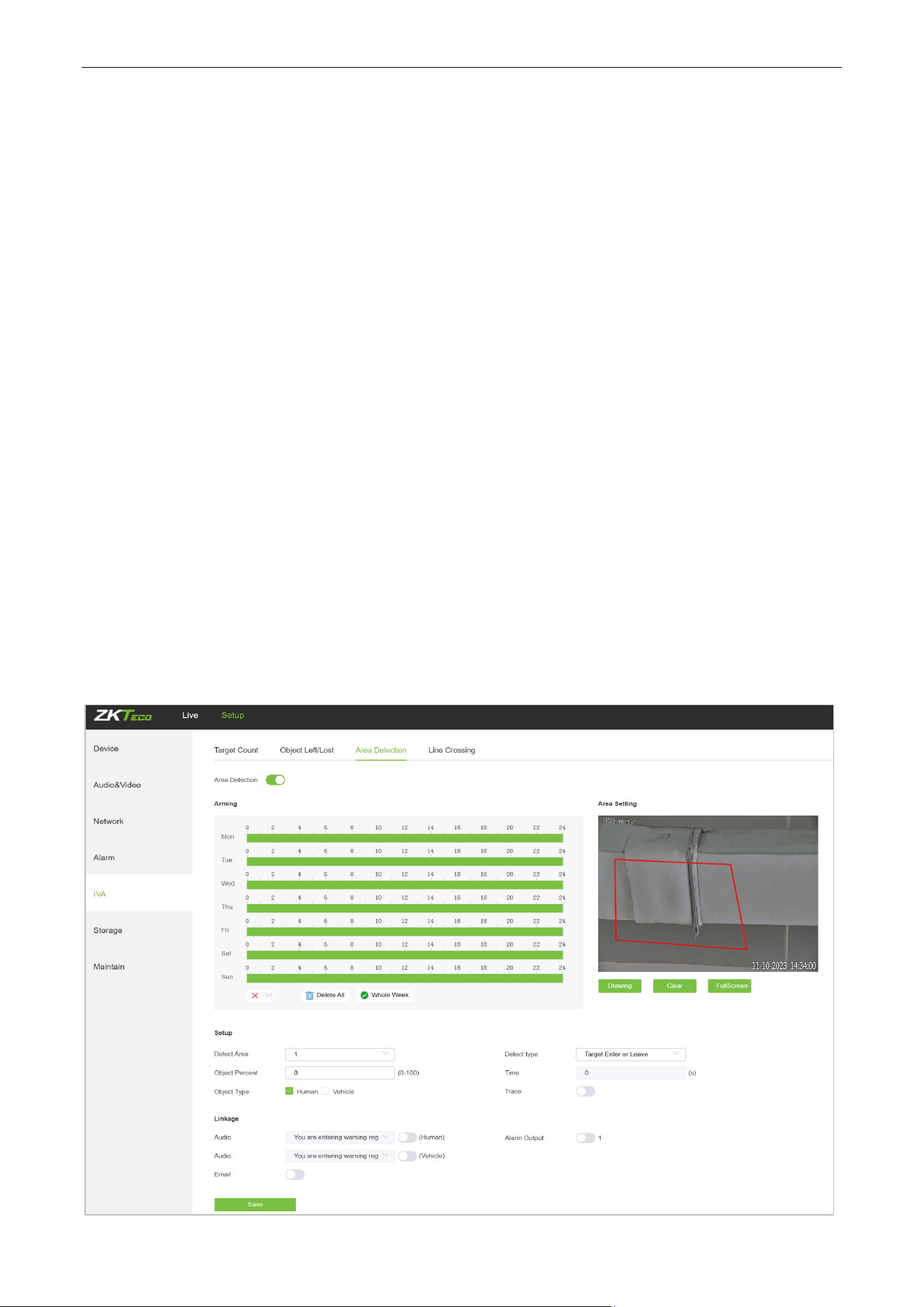
5.15. Area Detection (Intrusion Detection)
Below is the Area Detection setting interface of the IP camera:

Biosense Series Network Camera User Manual
Page | 35 Copyright©2024 ZKTECO CO., LTD. All rights reserved.
Enable: Enable or disable the area detection function.
Arming Schedule: Arming schedule can be set from Monday to Sunday.
Area Setting: Click on “Drawing”, then left-click and drag the mouse button to set the detect zone on
the area settings preview interface. Click on “Stopping”to complete the setting, then the system will
detect, and monitor objects appeared in the selected area.
Clear: Click on “Clear” to delete all zones.
Detect Area: Add controlled zones (max. 4).
Trace: When the tracking function is enabled, when the human/vehicle alarm is triggered, the camera
will track the target that triggered the alarm first. After 5 seconds of losing the target, the camera will
return to the guard position to continue monitoring the target area. Please note that enabling this
function will interrupt the camera's current cruise or track task.
Detect Type: Set the target detect type. There are four detection types, all of them will trigger the alarm.
“Target enter” represents that the camera will trigger the alarm once it detects that a target enters the
monitored zone; “Target leave” represents that the camera will trigger the alarm once it detects that a
target leave the zone; “Target enter or leave” represents that the camera will trigger the alarm once it
detects that a target enters and/or leave the zone. The last type is that the camera will trigger the alarm
once it finds that the time that a target staying in the controlled area exceeds the upper limit of the set
and allowed duration.
Object Percent: Sets the size of the object that triggers the alert. If objects smaller than the preset value,
such as mosquitoes and leaves, enter the monitoring area, the alarm will not be triggered.
Object Type: Set the detection object to be human or vehicle, and an alarm will be triggered when the
object detected in the area is the set value.
Detect Time: When the staying time of the set target in the monitored area exceeds the set duration,
the system will trigger the alarm.
Email: Click on “Email”. Once an alarm is triggered, an email will be automatically sent to the appointed
mailbox.
Snap: Click on “Snap”. Once an alarm is triggered, a signal will instantly be sent to the camera to take a
snapshot and store it in the TF card.
Record: Click on “Record”. Once an alarm is triggered, a signal will instantly be sent to the camera to
record a video and store it in the TF card (for cameras which support TF cards only).
Alarm Output: There should be an active alarm device inserted into the IPC alarm output port. Once
an alarm event is triggered, the IPC and alarm device will set off the alarm.
PTZ: Enable or disable PTZ function.
Snap Interval: Set the time intervals for taking snapshots.
Biosense Series Network Camera User Manual
Page | 36 Copyright©2024 ZKTECO CO., LTD. All rights reserved.
Snap Number: Set the number of snapshots taken each time.
Audio: Turn on the corresponding human/vehicle option to play the selected voice when the alarm is
triggered. For voice settings, please refer to Section 5.37.
After completing all parameters settings, click on “Save”, then the settings will take effect immediately.
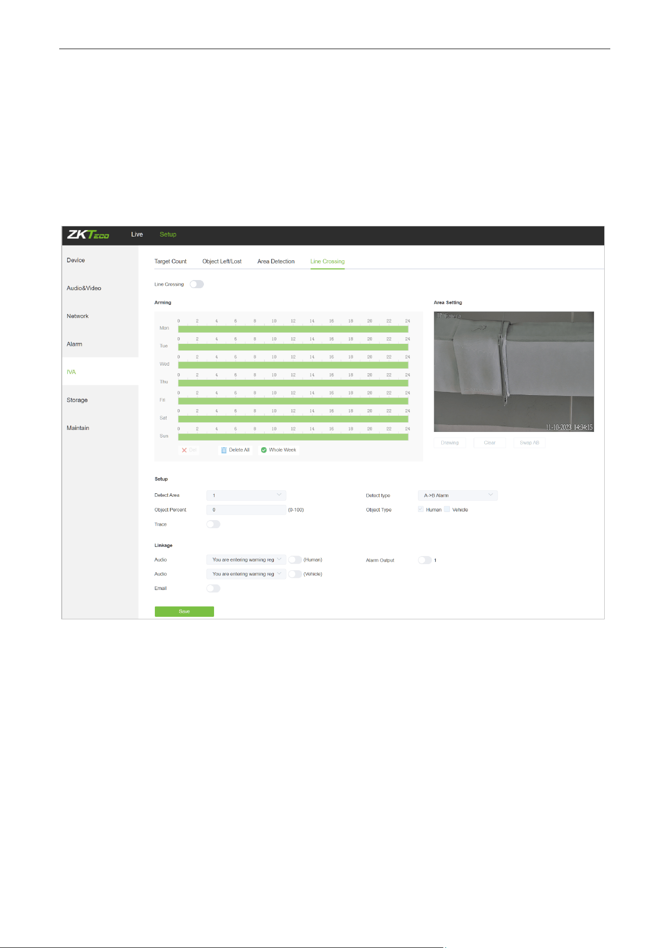
5.16. Line Crossing (Tripwire)
Below is the Line Crossing setting interface of the IP camera:
Enable: Enable or disable the virtual guard function.
Arming Schedule: Arm schedule can be set from Monday to Sunday.
Area Setting: Click on “Drawing”, then left-click and drag the mouse to set guard lines on the area
settings preview interface. Click on “Stopping” to complete the setting. When a target passes through
the guard line, the system will trigger the alarm.
Trace: When the tracking function is enabled, when the human/vehicle alarm is triggered, the camera
will track the target that triggered the alarm first. After 5 seconds of losing the target, the camera will
return to the guard position to continue monitoring the target area. Please note that enabling this
function will interrupt the camera's current cruise or track task.
Clear: Click on “Clear” to delete all zones.
Swap AB: Click on “Swap AB" to swap the positions of A/B ports.

Biosense Series Network Camera User Manual
Page | 37 Copyright©2024 ZKTECO CO., LTD. All rights reserved.
Detect Area: To add new guard lines (max. 4 guard lines).
Detect Type: Set the guard lines to trigger the alarm. “A→B” refers to targets passing through the guard
lines from area A to area B will trigger the alarm. “A←→B” refers to targets passing through the guard
lines either from area A to area B or from area B to area A will trigger the alarm.
Object Type: Set the detection object to be human or vehicle, and an alarm will be triggered when the
object detected in the area is the set value.
Object Percent: Sets the size of the object that triggers the alert. If objects smaller than the preset value,
such as mosquitoes and leaves, enter the monitoring area, the alarm will not be triggered.
Email: Click on “Email”. Once an alarm is triggered, an email will be automatically sent to the appointed
mailbox.
Record: Click on “Record”. Once an alarm is triggered, a signal will instantly be sent to the camera to
record a video and store it in the TF card.
Alarm Output: There should be an active alarm device inserted into the IPC alarm output port. Once
an alarm event is triggered, the IPC and alarm device will set off the alarm.
PTZ: Enable or disable PTZ function.
Snap Interval: Set the time intervals for taking snapshots.
Snap Number: Set the number of snapshots taken each time.
Audio: Turn on the corresponding human/vehicle option to play the selected voice when the alarm is
triggered. For voice settings, please refer to Section 5.37.
After completing all parameters settings, click on “Save”, then the settings will take effect immediately.
Biosense Series Network Camera User Manual
Page | 38 Copyright©2024 ZKTECO CO., LTD. All rights reserved.
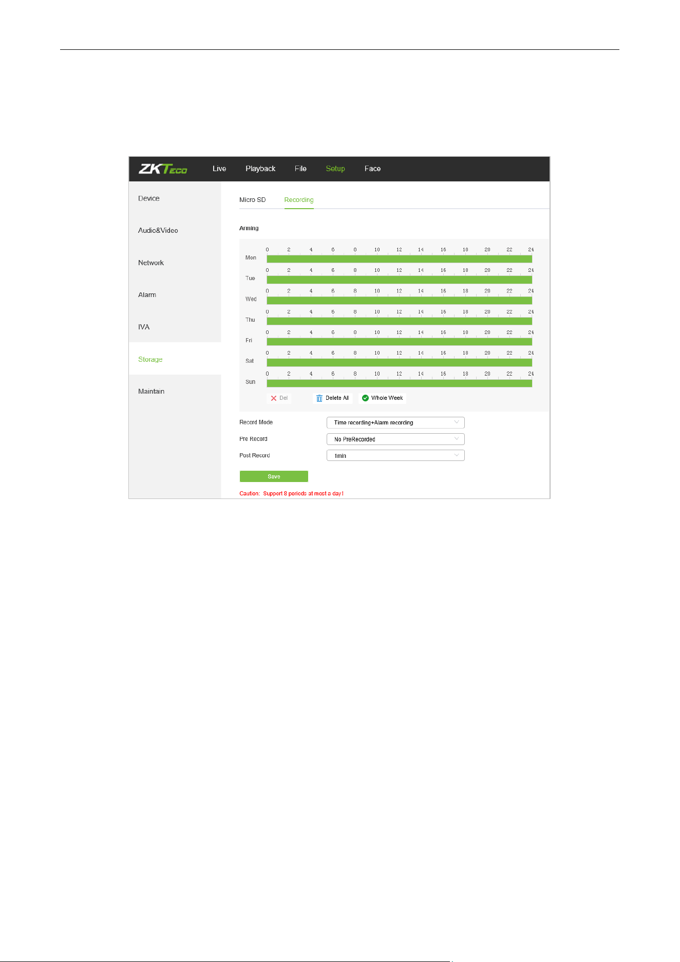
5.17. Video Plan
Only displayed on TF Card supported camera.
Below is the Video Plan setting interface of the IP camera:
Video Mode: Select a video mode. There are four modes available: Time recording + Alarm recording,
Time recording, Alarm recording, No video.
Week: Set the recording time from Monday to Sunday.
Pre Record: Set pre-recording time.
Post Record: Set the recording delay time.
Video Edge IP Address: Enter the IP address of NVR or the server.
After completing all parameters settings, click on “Save”, then the settings will take effect immediately.
Biosense Series Network Camera User Manual
Page | 39 Copyright©2024 ZKTECO CO., LTD. All rights reserved.
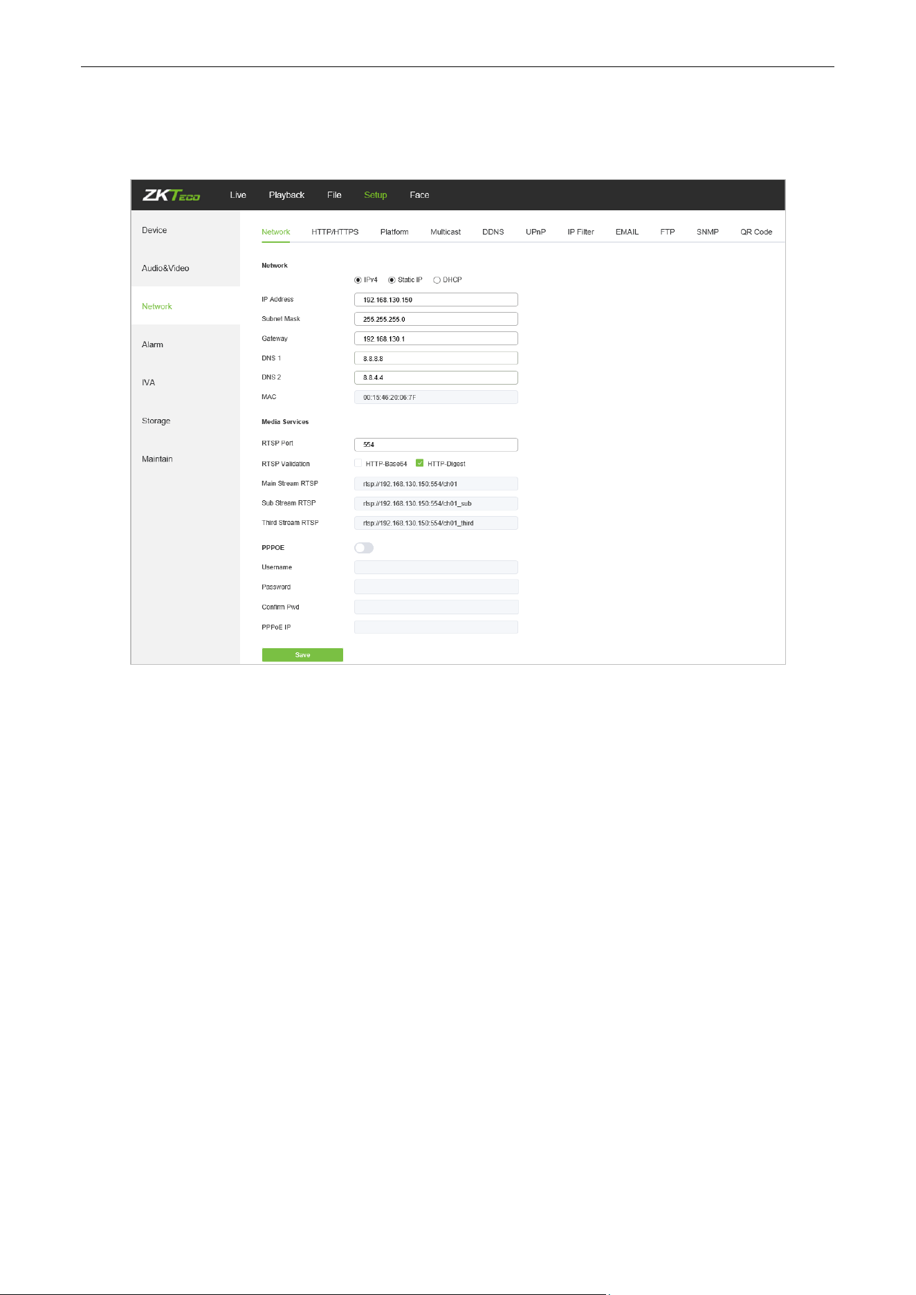
5.18. Network Settings
Below is the Network Settings interface of the IP camera:
IPV4: IP protocol version No. is 4.
Static IP: The device IP address is permanent.
DHCP: Enable DHCP, then the IP camera will obtain the IP address from the router automatically.
IP Address: Input the corresponding numbers to change the IP address.
Subnet Mask: Input the corresponding IP subnet mask.
Gateway: Input the corresponding gateway address.
DNS 1: IP address of the DNS server.
DNS 2: Another IP address of the DNS server.
RTSP Port: Access the device which needs to map RTSP with a domain name; the default port is 554.
RTSP Validation: Choose a RTSP verification mode from Http-Base64, Http-Digest. After choosing and
activating the corresponding RTSP verification mode, during playing RTSP real-time stream, RTSP
validation operations need the user name and password for verification.
RTMP Port: Domain name, which is used to access the device which needs to map RTMP; the default
port is 1935.
Username: PPPOE user name
Passwords: PPPOE password
Biosense Series Network Camera User Manual
Page | 40 Copyright©2024 ZKTECO CO., LTD. All rights reserved.
Confirm Pwd: Confirm password: Enter the password repeatedly
PPPOE IP: IP setting of PPPOE
After completing all parameters settings, click on “Save”, then the settings will take effect immediately.
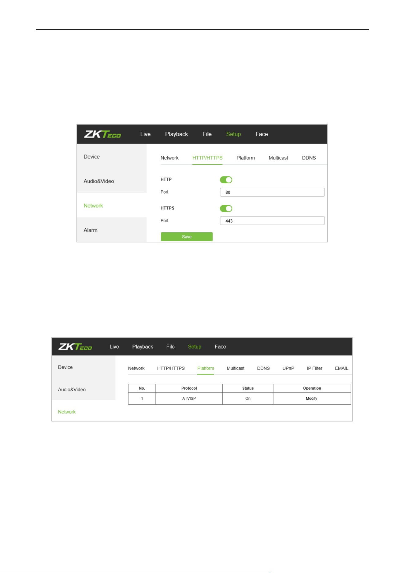
5.19. HTTP/HTTPS
In the HTTP/HTTPS setting interface, users can make PC log in normally via HTTP/HTTPs.
Enable: Enable or disable HTTP/HTTPS function.
HTTP port: Port range is 1~65524. The default value is 80.
HTTPs Port: HTTPs communication port, range is 1~65534, default is 443.
5.20. Management Platform
Below is the Management Platform interface of the IP camera:
Users may activate or deactivate a protocol and modify the protocol information here.
Biosense Series Network Camera User Manual
Page | 41 Copyright©2024 ZKTECO CO., LTD. All rights reserved.
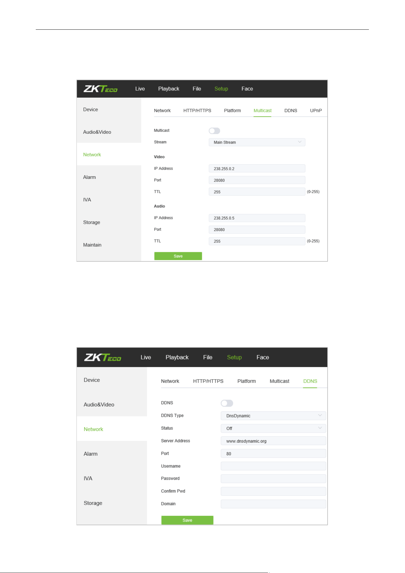
5.21. Multicast Configuration
Below is the Multicast Config interface of the IP camera:
Multicast configuration is disabled by default. By clicking on “Enable Multicast", users may set the IP address,
port and TTL of main stream video/audio, sub stream video/audio.
5.22. DDNS Settings
DDNS is implemented through a dynamic domain resolution server. It requires a fixed IP address on of the
device running on the server. The DDNS setting interface of the IP camera is as shown below:
Biosense Series Network Camera User Manual
Page | 42 Copyright©2024 ZKTECO CO., LTD. All rights reserved.
Enable DDNS: Enable or disable DDNS function.
DDNS Type: Select a DDNS server type from Dyndns, PeanutHull, NO-IP, 3322, and DnsDynamic.
Status: Turn on or off the DDNS.
Server Address: Input a server name, for example, dynupdate.no-ip.com.
Port: Input a port. The default port is 80.
User Name: Input a user name.
Password: Input a password.
Confirm Pwd: Input the password again to confirm.
Domain: Input the second domain.
After completing the parameters settings, click on “Save”, then the settings will take effect immediately.
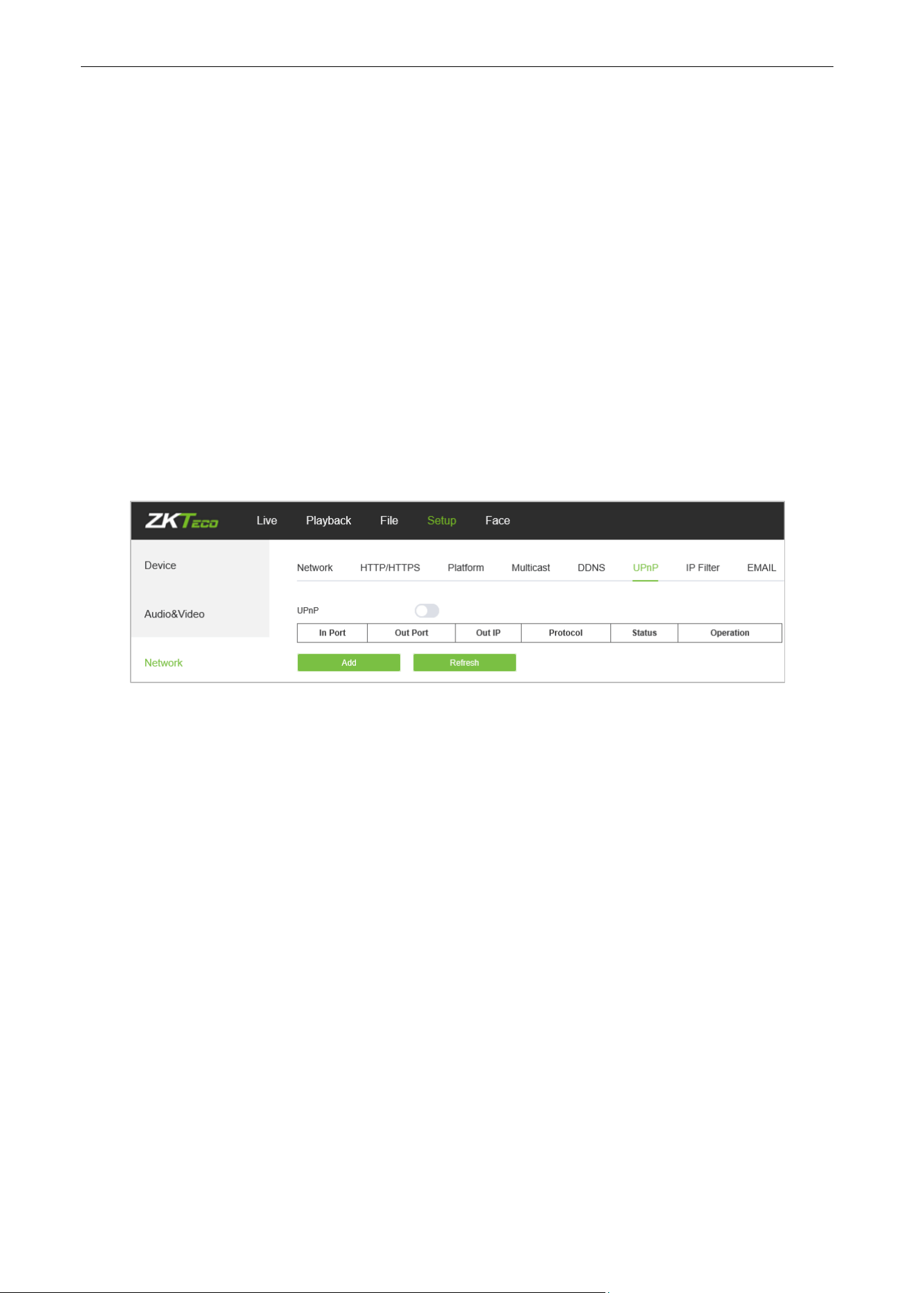
5.23. UPnP Settings
Below is the UPnP Settings interface of the IP camera:
Enable UPnP: Activate or deactivate the UPnP function. When it is enabled, the device can port
mapping through the router.
Add: User may add TCP/UDP protocol, set internal and external port.
Biosense Series Network Camera User Manual
Page | 43 Copyright©2024 ZKTECO CO., LTD. All rights reserved.
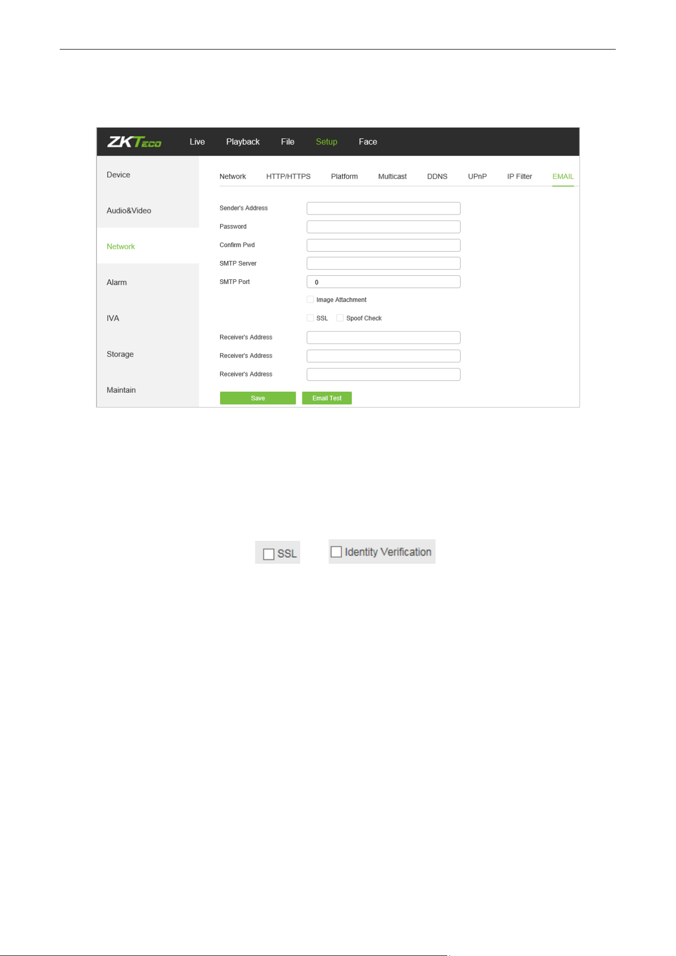
5.24. Email Settings
Below is the Email Settings interface of the IP camera:
Sender Address: Input the email address of the sender.
Password: Input the password of the outbox.
Confirm Pwd: Input the password again to confirm.
SMTP Server: Input the SMTP server address of the outbox.
SMTP Port: Input the SMTP server port of the outbox.
SSL/Identity verification: Tick and to send the email correctly and
safely.
Receiver's Address: Input the address of the inbox, fill in the address of the receiving email; you may
fill in 3 other receivers’ addresses.
After completing all parameters settings, click on “Save”, then the settings will take effect immediately.
Biosense Series Network Camera User Manual
Page | 44 Copyright©2024 ZKTECO CO., LTD. All rights reserved.
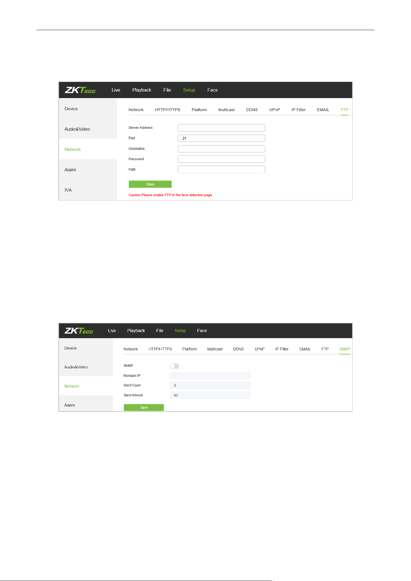
5.25. FTP Settings
Below is the FTP Settings interface of the IP camera:
Server Address: Input the FTP Server address.
Port: Input the FTP server port.
Username: Input the FTP server username.
Password: Input the FPT server password.
Path: Input the file upload path.
5.26. SNMP Settings
Below is the SNMP Settings interface of the IP camera:
Enable: Enable or disable SNMP service.
Manager IP: Messages will be sent to this manager IP address.
Send Count: The maximum number of messages to be delivered when an alarm is triggered. The value
ranges from 1 to 5.
Send Interval: Interval between messages sending. The range is 60-250s.
Biosense Series Network Camera User Manual
Page | 45 Copyright©2024 ZKTECO CO., LTD. All rights reserved.
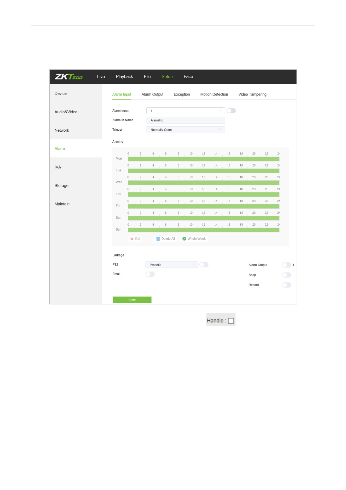
5.27. Alarm Input
Below is the Alarm Input setting interface of the IP camera:
Alarm Input: Select the alarm input port, then check the box to implement the following
parameters settings.
Alarm In Name: Input a name of an alarm.
Trigger Level: Select the alarm status: Normally Open/ Normally Close.
Arming Schedule: Arming schedule can be set from Monday to Sunday. You may set up to 8
schedules for a day.
Email: Click on “Email”. Once an alarm is triggered, an email will be automatically sent to the
appointed mailbox.
Snap: Click on “Snap”. Once an alarm is triggered, a signal will instantly be sent to the camera to take
a snapshot and store it in the TF card.
Record: Click on “Record”. Once an alarm is triggered, a signal will be transmitted to the camera to
Biosense Series Network Camera User Manual
Page | 46 Copyright©2024 ZKTECO CO., LTD. All rights reserved.
record a video and restore it in the TF card.
Alarm Output: Click on “Alarm Output”. There should be an active alarm device inserted into the IPC
alarm output port. Once an alarm event is triggered, the IPC and alarm device will set off the alarm.
Snap Number: Set the number of snapshots taken each time.
Snap Interval: Set the time intervals for taking snapshots.
PTZ: Enable or disable PTZ function.
Preset: When a signal triggers the alarm, it will link with the preset points.
After completing all parameters settings, click on “Save”, then the settings will take effect immediately.
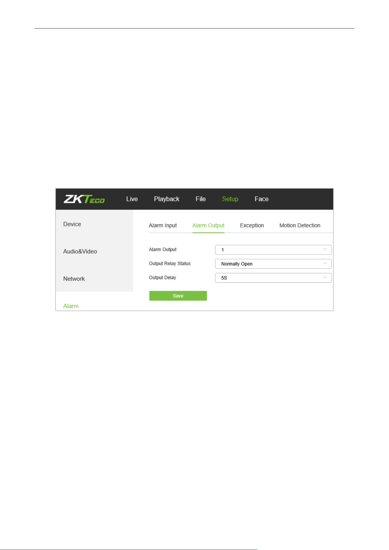
5.28. Alarm Output
Below is the Alarm Output setting interface of the IP camera:
Output Relay Status: Normally Open/ Normally Close.
Output Delay: Select alarm output delay time, which represents the corresponding output alarm
delay time after the alarm stops triggering.
After completing all parameters settings, click on “Save”, then the settings will take effect immediately.
Biosense Series Network Camera User Manual
Page | 47 Copyright©2024 ZKTECO CO., LTD. All rights reserved.
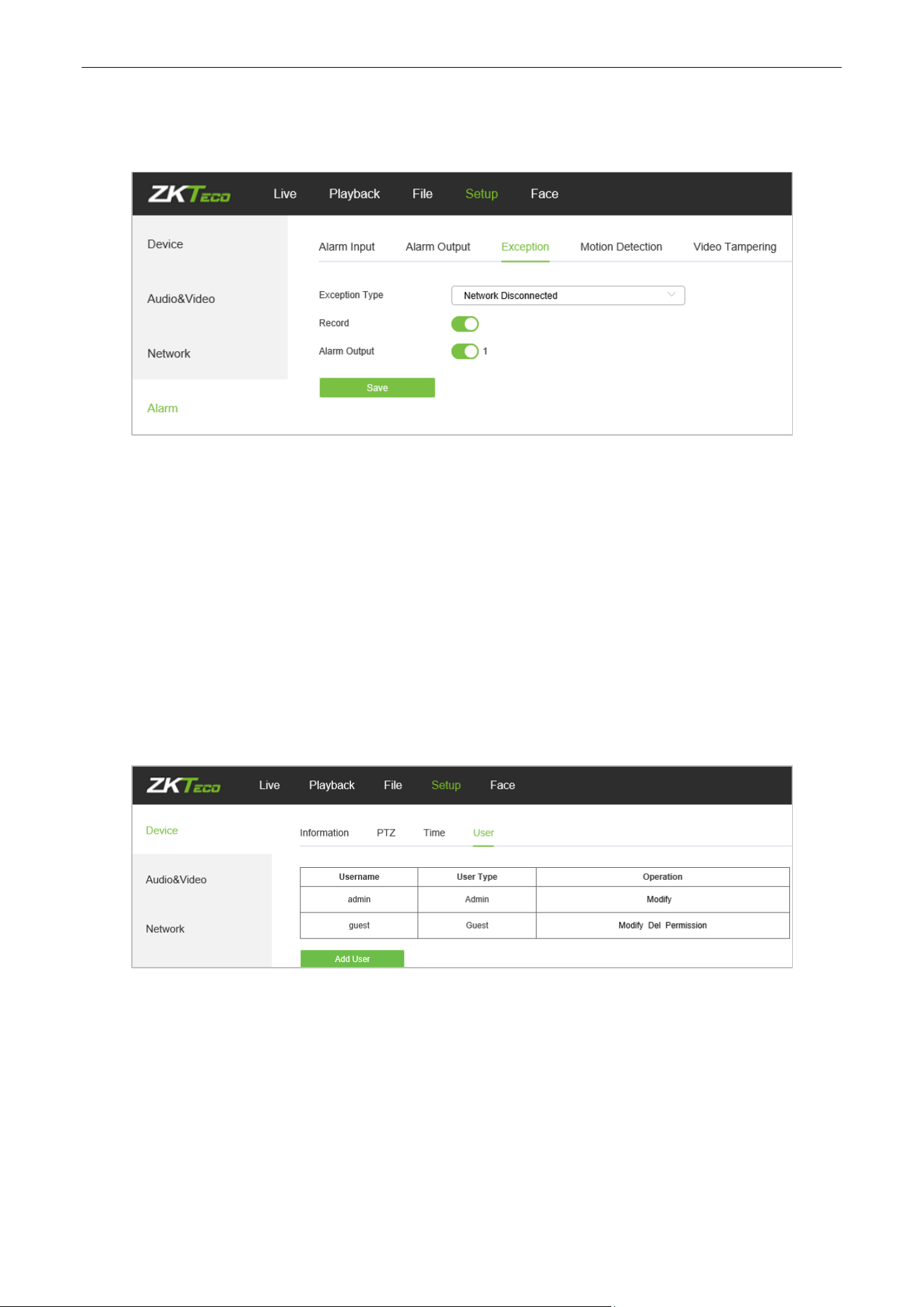
5.29. Exception
Below is the Exception interface of the IP camera:
Exception Type: Network Disconnected/ IP Address Conflict.
Record: Click on “Record”; when there is an abnormal event which triggers an alarm, the camera will
start recording
.
Alarm Output: Click on “Alarm Output”; the system will link with other alarm devices when there is an
abnormal event which triggers an alarm.
After completing all parameters settings, click on “Save”, then the settings will take effect immediately.
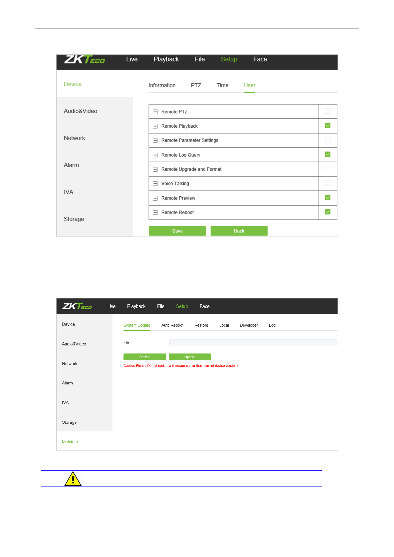
5.30. User Management
Below is the User Management setting interface of the IP camera. “admin” represents the administrator
(default); “default” represents standard users.
Modify: Admin may modify the login password; the default guest user may modify user type. New
users may modify their user names, passwords and user types. New users may select a “Guest” or
“Operator” account, and set different permission.
Del: Delete a new user.
Rights Permission: Permission assignment for default guest users and new users.
Add User: Add a new user.
Biosense Series Network Camera User Manual
Page | 48 Copyright©2024 ZKTECO CO., LTD. All rights reserved.
Log in with admin account, add a new user and assign permission, as shown in the following figure:
After completing all parameters settings, click on “Save”, then the settings will take effect immediately.
5.31. System Update
Below is the System Update setting interface of the IP camera:
File: Click on “Browse” to find and select an upgrade kit, then click “Update”.
Do not disconnect the power supply during upgrade.
Biosense Series Network Camera User Manual
Page | 49 Copyright©2024 ZKTECO CO., LTD. All rights reserved.
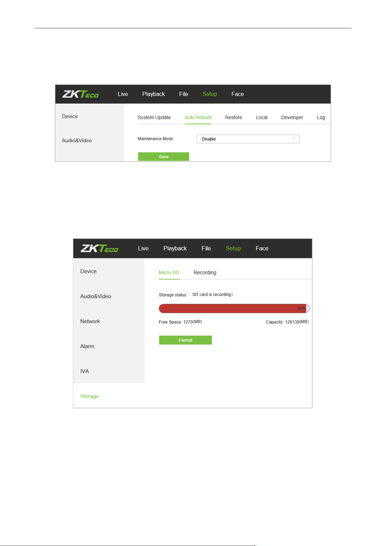
5.32. Auto Reboot
Below is the Auto Reboot setting interface of the IP camera. You may choose a maintenance mode from
Disable/ Every Day/ Every Week/ Once/ Every Month, then the IPC will reboot as set.
5.33. Storage Management
(Only displayed on TF Card supported camera)
Below is the Storage Management setting interface of the IP camera. You may view the capacity (MB), free
spare (MB), status of the current TF card, and format the TF card.
Note: Please disconnect the power supply before you insert or remove the TF card.
Biosense Series Network Camera User Manual
Page | 50 Copyright©2024 ZKTECO CO., LTD. All rights reserved.
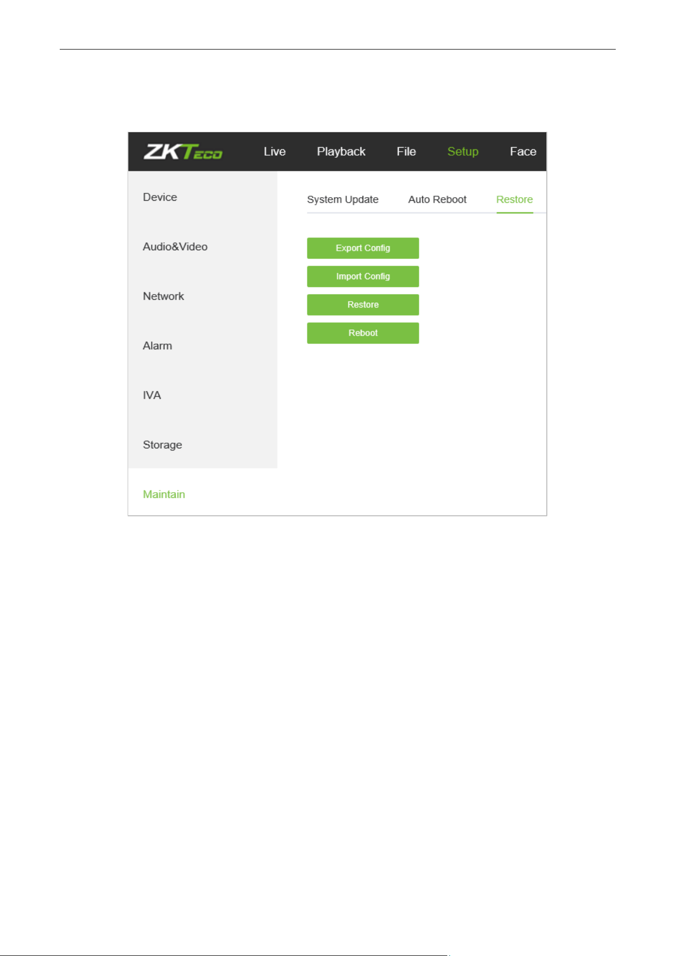
5.34. Restore
Below is the Restore interface of the IP camera:
Export Config: Export all configurations to PC or a USB.
Import Config: Import selected configuration to the system.
Restore: Restore the device to factory settings.
Reboot: Reboot the device.
Biosense Series Network Camera User Manual
Page | 51 Copyright©2024 ZKTECO CO., LTD. All rights reserved.
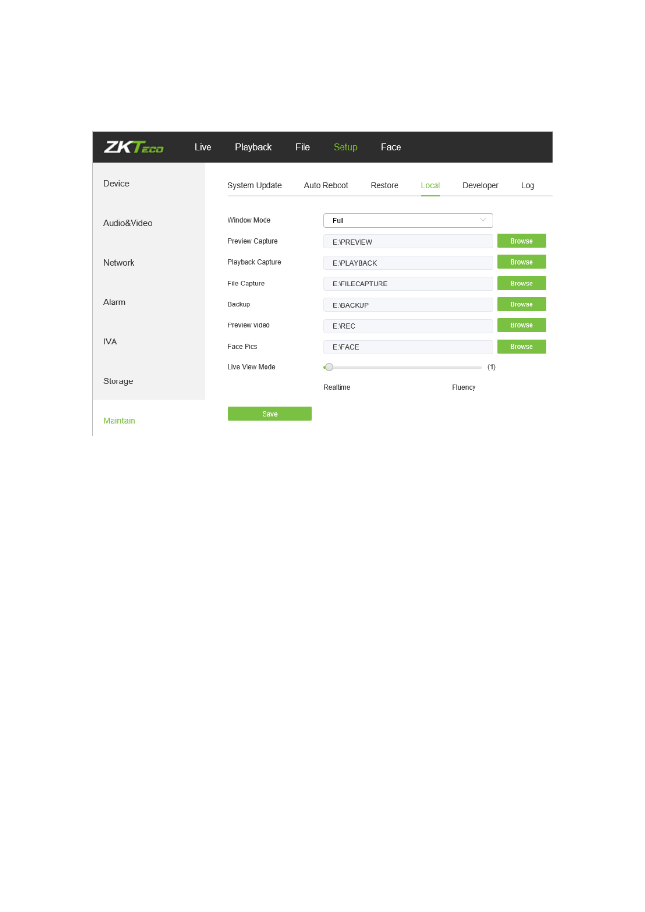
5.35. Local Settings
Below is the Local Settings interface of the IP camera:
Window Mode: Set the preview window mode (Full/ 4:3/ 16:9/ Original Image).
Preview Capture: Select and modify the storage path of captured files.
Playback Capture: Select and modify the storage path of playback files.
File Capture: Select and modify the storage path of captured files.
Backup: Select and modify the storage path of backup files.
Preview Video: Select and modify the storage path of the video record file.
Face Pics Path: Select and modify the storage path of the video record file.
Live View Mode: Realtime/ Fluency. The value is adjustable.
After completing all parameters settings, click on “Save”, then the settings will take effect immediately.
Biosense Series Network Camera User Manual
Page | 52 Copyright©2024 ZKTECO CO., LTD. All rights reserved.
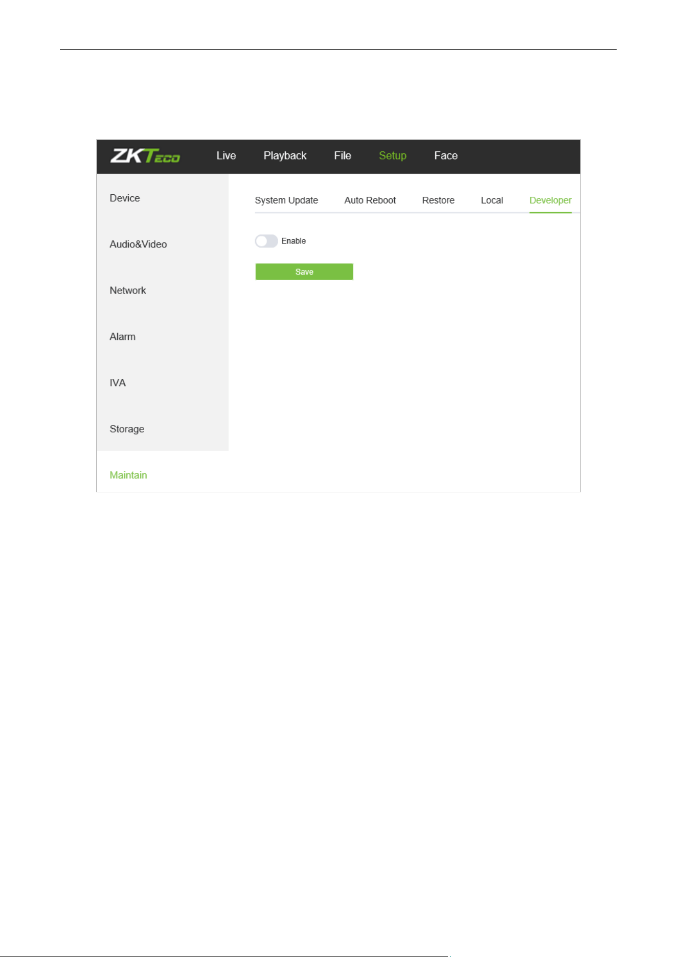
5.36. Developer
Below is the Developer interface of the IP camera:5.37
Biosense Series Network Camera User Manual
Page | 53 Copyright©2024 ZKTECO CO., LTD. All rights reserved.
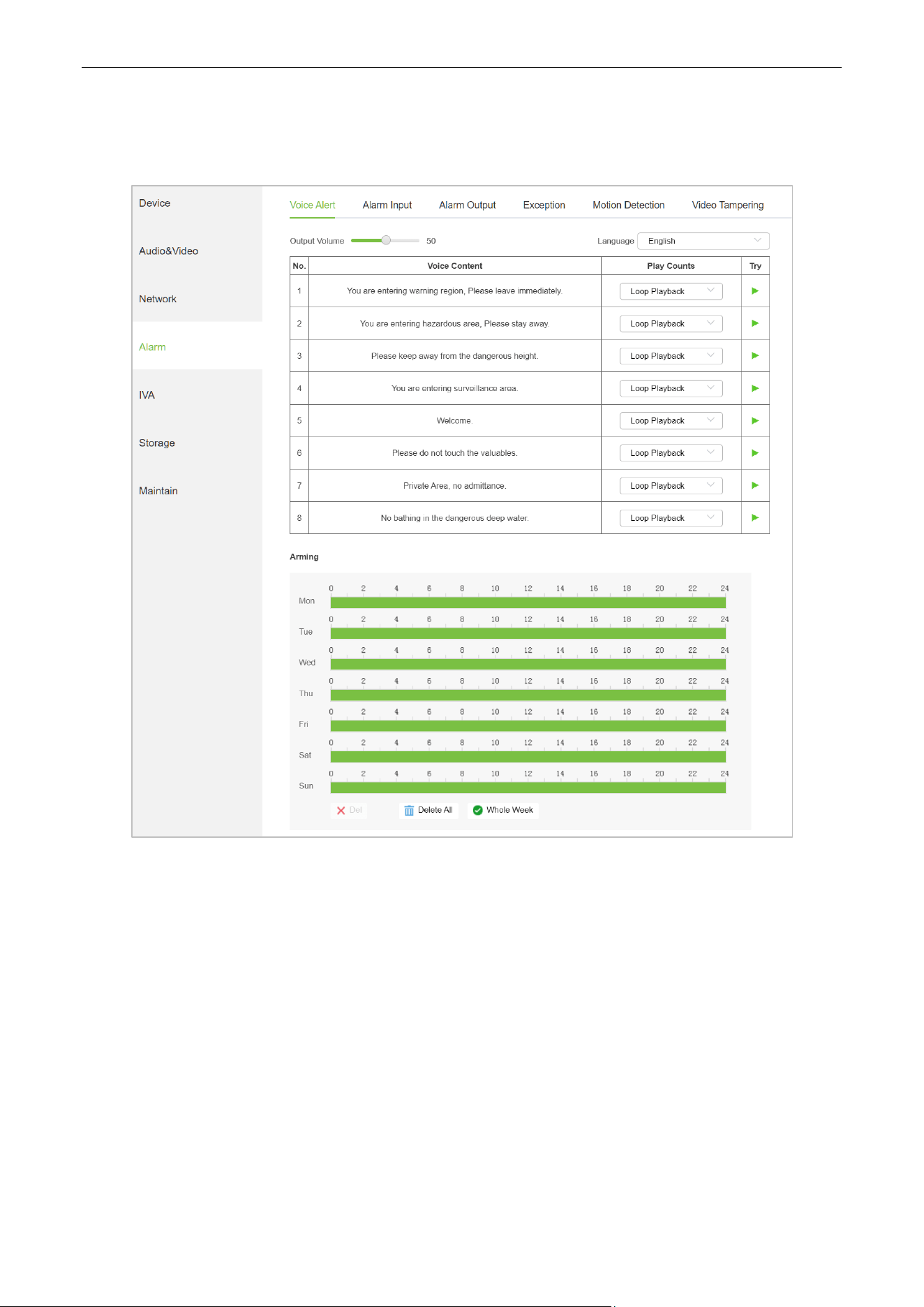
5.37. Voice Alert
On this page, you can set the type and volume of sound emitted by the device:
Output: You can adjust the volume of the device playback. The larger the value, the louder the
volume
Language: You can choose the language of the broadcast, including Chinese and English. Click the
"Try" button to listen to a trial.
Play Counts: The number of times the voice has been played. If Loop Playback is selected, the voice
will continue to play during the alarm period until the alarm stops.
Arming: You can set the weekly alarm time period, and the device will play the alarm sound during
the specified time period.
Biosense Series Network Camera User Manual
Page | 54 Copyright©2024 ZKTECO CO., LTD. All rights reserved.
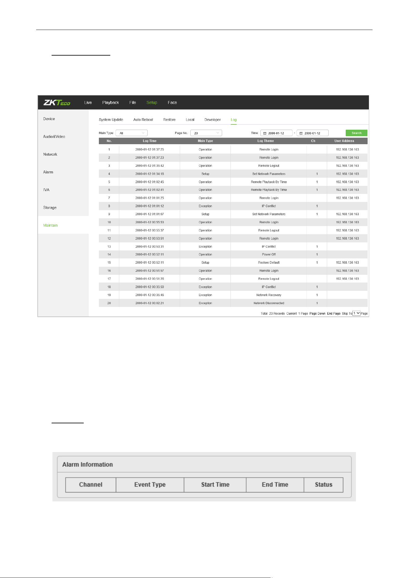
6. Log Search
Click Search on the Log interface, check device log according to the video type and date time, as shown
in the below figure:
Main Type: Select the type of logs to search for. You may choose among All/ Alarm/ Exception /
Operation/Parameter or click “All” to search all types of logs.
Start Time/ End Time: Select the time period of logs to check.
Page No.: Select the number of logs to display on each page.
After completing all settings, click on “Search”, then the log information will display on the left.
7. Alarm
Below is the Alarm interface of the IP camera. Information about alarms will be shown as follows.
Biosense Series Network Camera User Manual
Page | 55 Copyright©2024 ZKTECO CO., LTD. All rights reserved.
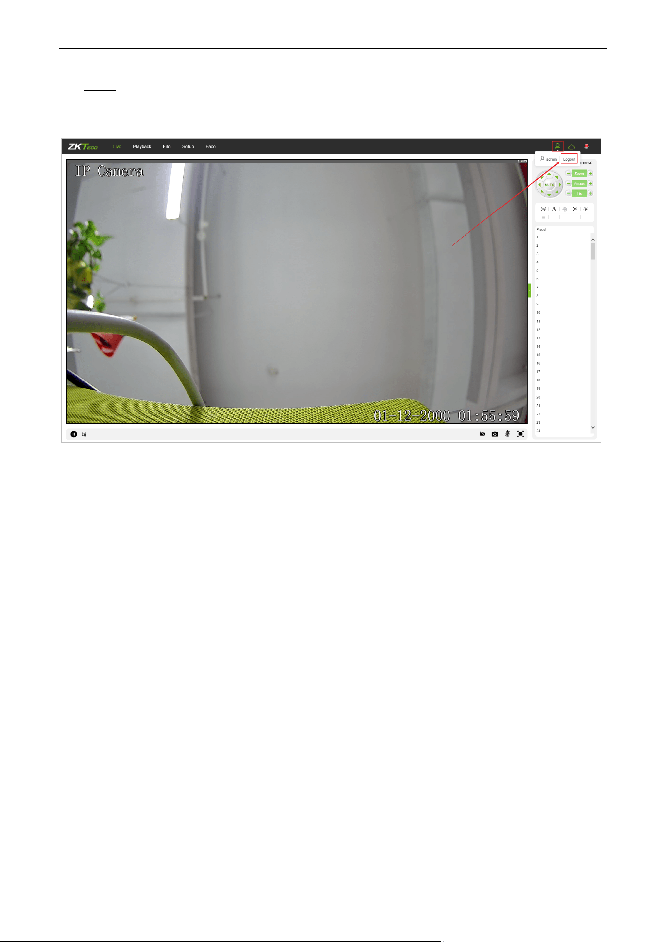
8. Exit
Click on “Logout” to log out, as shown in the following figure:
Biosense Series Network Camera User Manual
Page | 56 Copyright©2024 ZKTECO CO., LTD. All rights reserved.
9. FAQ
Question 1: No video output on the IE browser.
Possible reason: The web plugin was not installed.
Solution: Download and install the web plugin according to the webpage prompt when it is the first visit.
We only support IE browser currently.
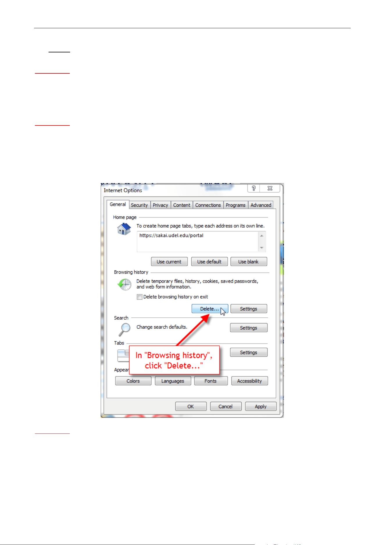
Question 2: Failed to log in after upgrading the program.
Solution: Delete IE Caches, and re-install the web plugin.
Specific steps: Open IE browser, choose “Tool” -> “Internet Options”, then, “General”->“Browsing history”,
and click on “Delete”. After that, select “Temporary Internet files” and confirm by choosing “Delete”. Then
back to the login page.
Question 3: The playback of video is not smooth.
Possible reason 1: The IP Camera frame rate is too low.
Solution: Set a higher frame rate on the respective interface by choosing “Setup->Streams->Frame Rate”.
Possible reason 2: There are too many users connected to the device.
Solution: Disable some of the clients or set a lower frame rate for the IP camera.

Biosense Series Network Camera User Manual
Page | 57 Copyright©2024 ZKTECO CO., LTD. All rights reserved.
Possible reason 3: The transmission data is large while the bandwidth is small, which leads to loss of data
packets.
Solution: Set a lower frame rate or resolution.
Question 4: Can’t access the IP camera on IE Browser?
Possible reason 1: The network is down.
Solution: Test the network on PC to confirm if the network works normally. Please make sure the network
cable is available and all RJ45 jacks are connected properly. Also, ensure that there is no computer virus
which may cause network issue as well.
If the PCs can ping each other, the network cable environment is normal. In this case, please check the
possible reasons below which may lead to the issue:
Possible reason 2: The IP address is in use by another device.
Solution: Disconnect with the IP camera network port, and directly connect the device with the PC, then set
up a new IP address for the camera.
Possible reason 3: The IP address is set up in another subnet.
Solution: Check the server’s IP address, subnet and gateway parameter, then set up the IP camera in the
same network.
Possible reason 4: The MAC address conflicted.
Solution: Modify the MAC address for IP camera.
Possible reason 5: The Web Port has been changed.
Solution: Connect with network administrator to get the correct port.
Question 5: No audio output.
Possible reason 1: The audio interface was not connected.
Solution: Please check the device audio interface and make sure the cables are connected property.
Possible reason 2: The audio function was not enabled on the IP Camera.
Solution: Please check if the audio configuration is enabled or not and select a desired mode.
Question 6: Search NVS can’t find the device.
Possible reason: The Search NVS software uses the multicast protocol to search for device network
information across network segments, and the firewall does not allow multicast data packets to pass, so the
software may not find the device.
Solution: Turn off the firewall.
Question 7
: Image is not clear enough.
Solution: Try adjusting the parameters for images to reasonable values. For details, please refer to Chapter
5.9 Image Parameters
.

Page | 58 Copyright©2024 ZKTECO CO., LTD. All rights reserved.
ZKTeco Industrial Park, No. 32, Industrial Road,
Tangxia Town, Dongguan, China.
Phone : +86 769 - 82109991
Fax : +86 755 - 89602394
www.zkteco.com
Copyright © 2024 ZKTECO CO., LTD. All Rights Reserved.


