1
MANUFACTURER: EURODIB
ADDRESS:
120 de la Barre, Boucherville, Qc, J4B 2X7 (Canada)
334 Cornelia St #272, Plattsburgh, NY, 12901 (United States)
Issued on: 01.11.2022
INSTALLATION - USER -
MAINTENANCE MANUAL
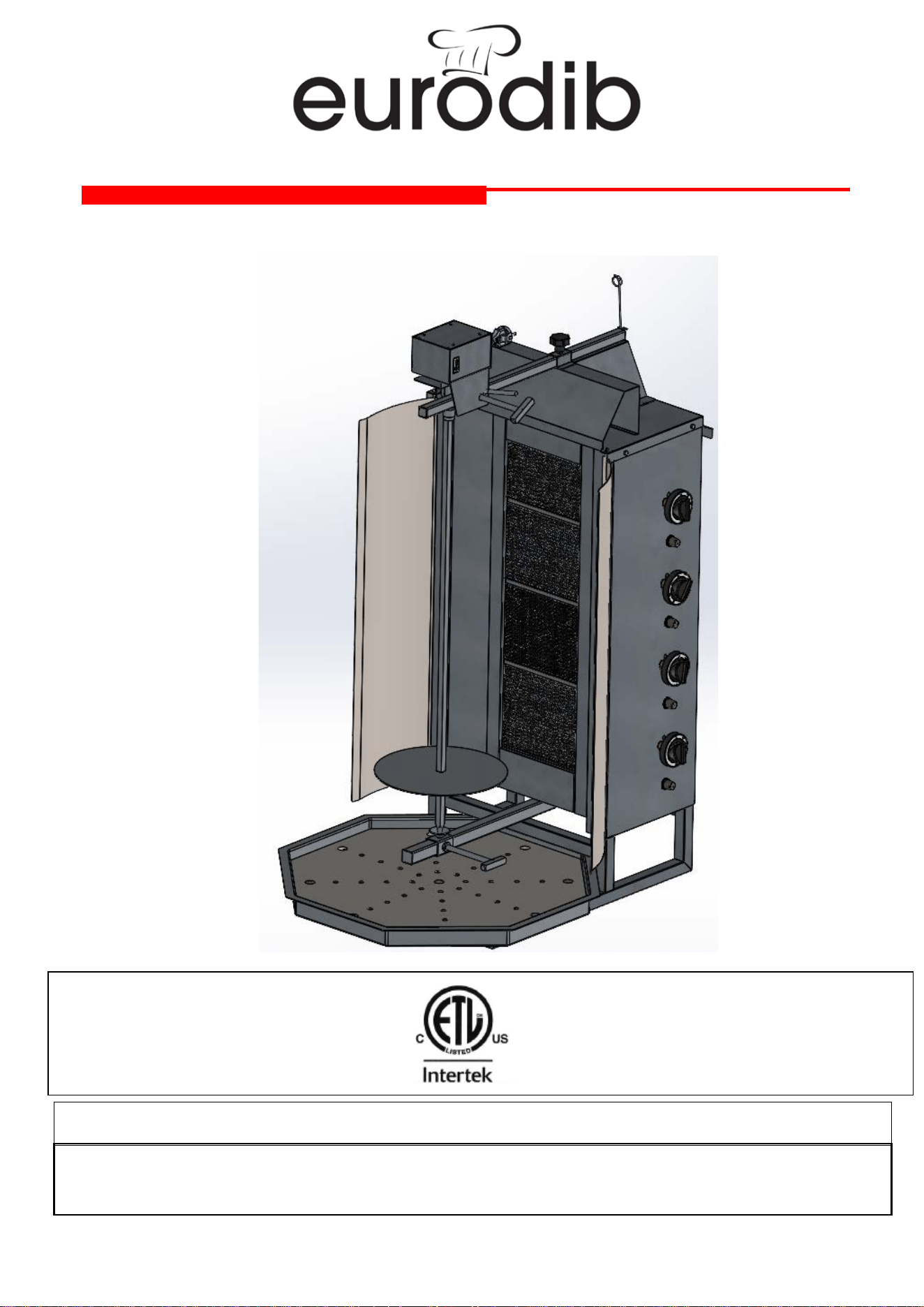
VERTICAL BROILER

2
1 – PREFACE
1.1 – Use of Installation – Operation & Maintenance Manual
2 – INSTALLATION INSTRUCTIONS
2.1 – Technical Instructions for Gas Connections
2.2 – Installation of the Appliance
2.3 – Technical Specifications
2.3.1 – Table of Burners Depending on the Injector Type of Gas Used
2.3.2 – Technical Specifications of Gas Vertical Broiler
2.3.3 – Instructions for Gas Conversions
2.3.4 – Gas System Diagram
2.4 – Motor
2.5 – Gas Connection Diagram
2.5.1 – Vertical Broiler with Motor on Top
3 – OPERATION AND MAINTENANCE INSTRUCTIONS
3.1 – Installing the Appliance
3.1.1 – Vertical Broiler with Motor on Top
3.2 – Purpose of Use
3.3 – Warnings
3.4 – Operation
3.5 – Operation with Motor
3.5.1 – Vertical Broiler with Motor on Top
3.6 – Operation without Motor
2.5.1 – Vertical Broiler with Motor on Top
3.7 – Clean-Up
3.8 – Maintenance
4 – WARRANTY
TABLE OF CONTENTS

3
Dear User,
Thank you for purchasing our Eurodib product and for your confidence in our
company. Our appliances are produced in compliance with international
standards. IMPORTANT: Please read and ensure that all users read this manual
in order to achieve the desired performance that you expect; and to enable you
to use this Eurodib appliance for many years.
☞ Please read and ensure that your operation personnel read this user’s
manual carefully before installing and using the appliance.
☞ The manual containing information about installation, usage and
maintenance of our product you purchased should be read carefully.
Please ensure that power supply connections to the appliance are already
installed by qualified personnel according to local regulations, before our
authorized service arrive for any service work to this appliance. If our
authorized service determines that the necessary repair(s) to be done are a
result of the faulty installation on your part, the warranty shall not be covered.
☞ If you do not have enough information, please contact us:
Monday-Friday 8:30 AM/5:00 PM (Eastern Standard Time)
Toll Free: (888) 956-6866
Local: (450) 641-8700
Toll Free Fax: (877) 956-6867
Warranty, Service, Technical Support: service@eurodib.com
Customer Service: customerservice@eurodib.com
☞ We expect you to have the best performance from our product!
1.1 – Use of Installation – Operation & Maintenance Manual
Dear customer please read this User’s Manual carefully in order to prevent your
appliance from damages, and to achieve maximum efficiency throughout the
economic life of the appliance.
1 - PREFACE
4
2.1 – Technical Instructions for Gas Connections
Initial installation and operation of the appliance must be carried out by an Authorized
Service in compliance with technical requirements and local directives related to gas
connections.
All gas connections of the appliance must comply with ISO 7 – 1 or ISO 228 – 1
standard.
2.2 – Installation of the Appliance
The appliance must be installed on a stable, even and balanced ground made of stainless
steel. This stainless steel surface must be in a form preventing fat from flowing down from the
surface and spilling The appliance should never be installed on a plastic or wooden surface. It
must be installed so that at least 20 cm distance is maintained between the appliance and the
wall, during its use.
Gas connections of the vertical broiler must be done in compliance with the regulations in
force.
2.3 – Technical Specifications
The manufacturer reserves the rights to alter design and specifications without notice
AN ELECTRICAL AND GAS INSTALLATION COMPLYING WITH THE RELEVANT
LOCAL REGULATIONS MUST BE PRESENT AT THE FACILITY, BUILDING AND SIMILAR SITE
WHERE THE VERTICAL BROILER WILL BE INSTALLED; NECESSARY PRECAUTIONS MUST
ALSO BE TAKEN TO ENSURE HEALTH AND MATERIAL SAFETY.
OTHERWISE OUR COMPANY WILL NOT BE RESPONSIBLE FOR THE
CONSEQUENCES.
!
The appliance should be operated under well ventilated conditions. The ventilation
system must be of non-flammable character, and the ventilation funnel must be free
of any obstruction.
!
Power supply cords and gas connection hoses of the appliance installed by
the Authorized Service must not be extended and changed.
!
2 – INSTALLATION INSTRUCTONS

5
2.3.1 – Table of Burners Depending on the Injector Type of Gas Used
* Each burner capacity:
3.25 kW
GAS TYPE
Gas Connection
Natural Gas
7” – 8” WC
Propan
10” - 13” WC
POS
Machine Type
Size (in)
Burner Injector Diameter (mm)
1 GVB3
1/2"G
1,35 0,90
2 GVB4
1/2"G
1,35 0,90
2 – INSTALLATION INSTRUCTONS
Nominal power of the appliance cannot be changed upon customer’s request.
Any modification made on valves and injectors, leaves the appliance out of
warranty coverage. Otherwise our company will not be responsible for the
consequences.

6
2.3.2 – Technical Specifications of Vertical Broiler
Poz.
Product
Nr.
Power (BTU)
Meat Capacity
Weight
Skewer length
(inch)
Dimensions (HxWxD)
(inch)
1
GVB3
33268,38 40 kg (88 lbs)
24 kg (53 lbs)
28,98 38,85x17,72x22,4
2
GVB4
44357.84 80 kg (176 lbs)
27 kg (59 lbs)
35,43
45,27x17,72x22,4
2.3.3 – Instructions for Gas Conversions
• Gas conversions should only be carried out by staff qualified in gas conversion.
• Close the valves of the gas line or gas bottle supplying gas to the appliance.
• Disconnect gas connection of the appliance.
• Loosen the screws of the back panel and remove back panel of the appliance
• Demount and remove the tubes between the gas valve and the burners.
• By displacing its splint remove the connection, where the injectors on the
burner are attached.
• Install appropriate type of injectors for the gas type to be used, on burner
connections.
• Install the splint and the connection back and tighten.
2 – INSTALLATION INSTRUCTONS
PLEASE FOLLOW THE INSTRUCTIONS BELOW TO USE THE ROTISSERIE
APPLIANCE WITH A GAS TYPE VARYING FROM REGIONAL REQUIREMENTS!

7
• Re-mount the tubes between the gas valve and the burners. (Smear gearing of
the connection, where the collar on the tube and the tube are mounted to the
gas valve, with gas paste against gas leakage.)
• Change the labels of the appliance according to the gas conversion type.
• Connect the appliance to appropriate type of gas according to the gas
conversion.
• Check all connections for gas leakage. (Tests have to be carried out using
leakage spray or foam. Never check gas leakage with an open fire source like
match, lighter etc.)
• After the gas leakage test carry out combustion test for the appliance.
• If the heat of the appliance is not sufficient set the gas adjustment injector (by-
pass) on the gas valve appropriately using a screwdriver. (Since the by-pass
injector is opened into the gas flow path, do never remove the by-pass injector
during operation. Since the settings of the appliance are done by default as to
requested gas pressure; if gas conversion will not be carried out, these settings
should never be changed by the user. Re-mount the back panel if no problem
exists.
• If you follow these instructions you can use your appliance safely with the gas
type converted.
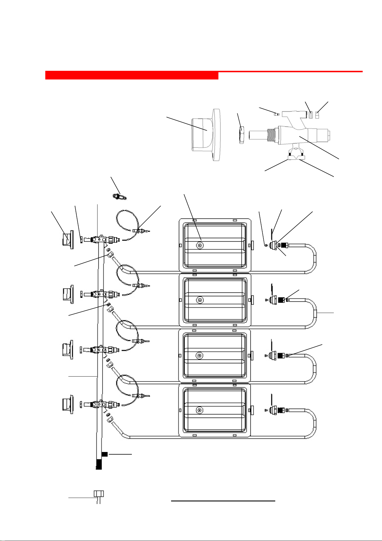
2.3.4 – Gas System Diagram
1 – Burner
2 – Burner connection
3 – Burner injector
4 - Splint
5 – Ring
6 – Burner collar
7 – Gas tube
8 – Gas valve
9 – Thermo-element
10 – Gas ramp
11 – Gas pressure control connection
12 – Piezo Igniter (4 pcs for GVB4,3 pcs for GVB3)
13 – Propane connection collar
14 – Gas valve button
15 – Gas valve nut
16 – Gas valve by-pass injector
17 – Gas valve collar
18 – Gas valve clamp
19 – Clamp screw
2 – INSTALLATION INSTRUCTONS
8
2 – INSTALLATION INSTRUCTONS
14
14
15
15
16
5
17
8
18
19
1
3
9
4
2
13
10
8
7
17
5
6
5
11
GAS SYSTEM DIAGRAM
5
12
9
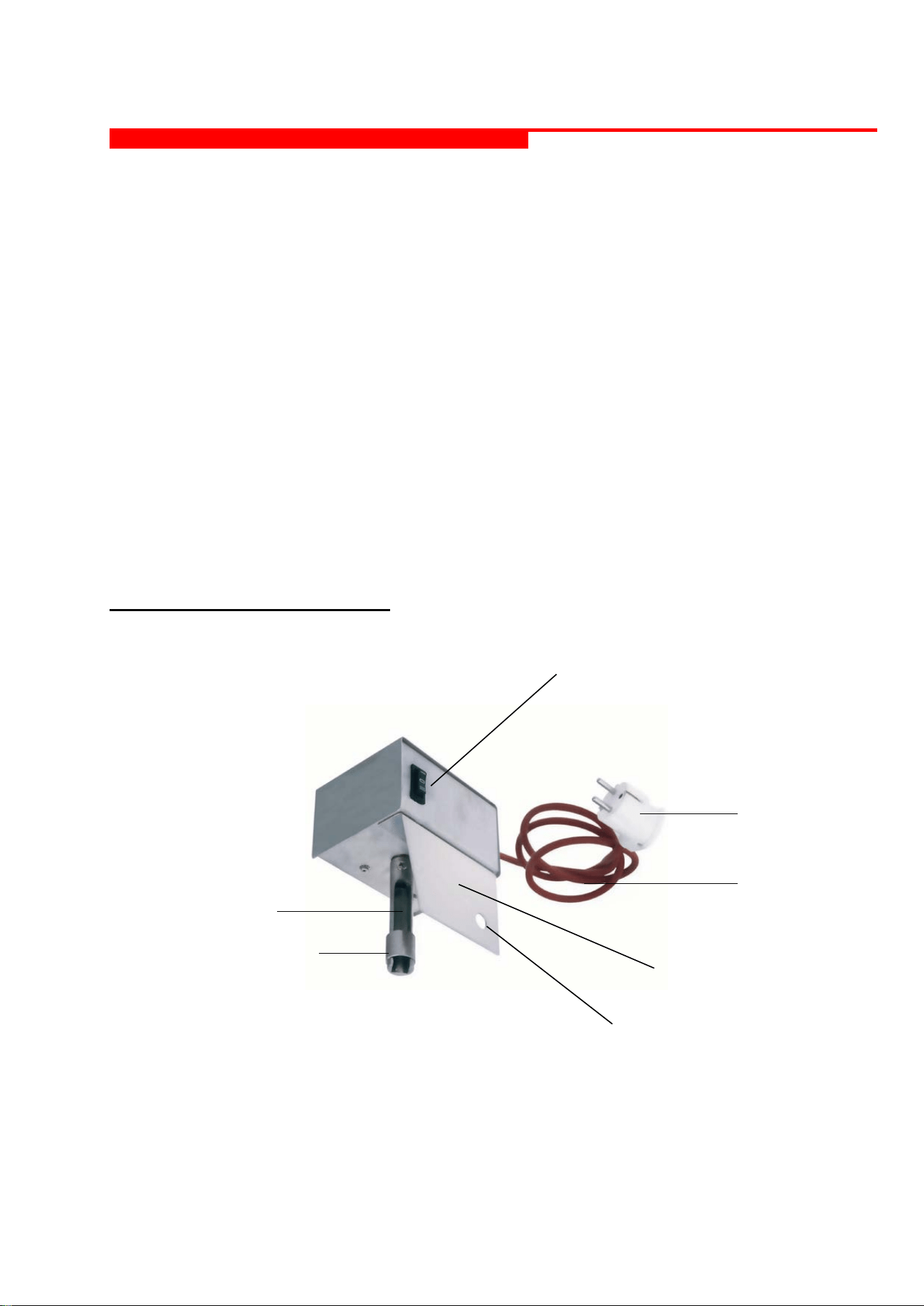
2.4 – Motor
Electrical motors can be operated two-ways (right/left). This way, each side of the
skewered meat can be grilled homogenously, and the appliance is operated using less
human effort.
* Do not clean the electrical motor with water. Wipe the frame of the motor with a moist
cloth, and then wipe it dry.
* Do not drop down the electrical motor.
* Protect the cord of the electrical motor from contacting directly with fire.
* Use the Heat Cap (5) being an original part of the appliance, in order to protect the
motor from excessive heat during operation. (Figure 1-b)
* Check the electrical cord of the appliance before each operation. Cords affected by
heat or cut due to incorrect operation may cause leakage current.
By following instructions stated above, maximum efficiency is achieved with the motor
of the product.
Motor Technical Specifications:
- 115 Volt (AC) NPE ~ / 60 Hz
- 1 rpm
3,5 W
Motor Cord
2 – INSTALLATION INSTRUCTONS
Plug
Rotisserie
Guide
Rotisserie Guide
Motor Fixing Plate
Mount Opening
Switch
10
2.5 – Gas Connection Diagram
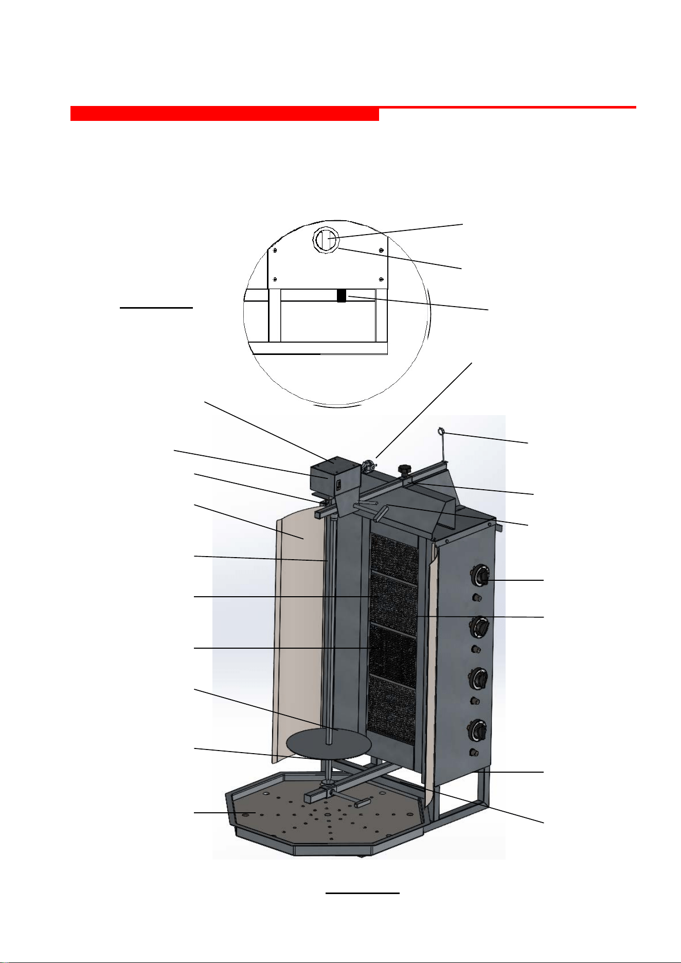
2.5.1 – Vertical broiler with Motor on Top
2 - Motor Cord
3 - Upper Slide
4 - Cord Holder
7 -Gas Valve Button &
Gas Valve
9 - Thermoelement
13 - Gas Connection &
Pressure Gauge
Connection
15 - Lower Slide
1 - Motor
5 - Heat Cap
8 - Guard Grating
10 - Burner
11 - Disc
12 - Splint
14 - Fat Tray
Figure 1 - b
6 - Skewer
16 – Counter-Arm
17 – Motor Plate
18 – Skewer Guide
2 – INSTALLATION INSTRUCTONS
Gas Valve &
Gas valve button
By-Pass Injector
Figure 1 - a
Gas Connection &
Pressure Gauge Connection

11
3.1 – Installing the Appliance
3.1.1 – Motor on Top (Figure 1 – b)
After installing the appliance in compliance with the regulations mentioned in the
User’s Manual of the motor on top type of vertical broiler, the fat tray and the motor
(Figure 1–b) are inserted, making the appliance ready for use. In these types of
appliances, unscrew upper and lower slide arms for the meat grilling. The distance
between the skewer (6) with meat on, and the burners is adjusted with the help of
these arms.
Make the gas connections at values as specified on appliance label and plug the
electrical cord in. Your appliance is ready for use.
3.2 – Purpose of Use
This vertical broiler was designed and manufactured to grill any kind of skewered meat
for commercial purposes, and cannot be used for different purposes.
3.3 – Warnings
* Before starting the appliance remove all protective PVC films and any other
packaging material, from the appliance.
* Do not leave the appliance unattended when operating.
* The appliance should only be operated under a chimney hood.
* The appliance should only operated by persons, who have read the user’s manual
and maintenance manual and are trained about the operation of the appliance.
* This appliance should only be operated on a stable, levelled surface made of
stainless steel.
* Gas connections must be checked for gas leakage.
* The appliance should be operated under well ventilated conditions. The ventilation
system must be of non-flammable character, and the ventilation funnel must be free of
any obstruction.
* When changing the location of the appliance, it must be turned off and cooled down.
* If the appliance is operated without motor (for motor on top type of vertical broilers)
use the original skewer turning arm, which can be mounted to the top of the skewer, to
rotate the meat.
* If gas odour is smelled, turn the gas valves of the appliance and all other gas valves
off, and ventilate the room. Call authorized service as soon as possible.
* Do never check gas leakage using a match or lighter. Check it using a gas leakage
spray or foam.
* All gas valves, main gas valves and power supplies must be turned off, after the
operation and in cases of emergency.
* The appliance should not be used beyond its purpose of use.
* The appliance should not be moved and jolted when operating.
* Beware from spilling of fat, when operating the appliance. Any spilled fat should be
cleaned up immediately. Otherwise accidents and serious injuries might arise from the
slippery surface caused by spilled fat.
* Do not hit and tilt the appliance when carrying it.
3 – OPERATION AND MAINTENANCE INSTRUCTIONS
12
* Do not locate any flammable material near the appliance. Do not operate the
appliance near easily flammable materials.
* If the appliance has to be located near to a wall, dividing wall, kitchen furniture,
decorative coating etc., these must definitely be of non-flammable material. Otherwise
these must be coated with non-flammable heat insulation material, and the fire
protection instructions must be strictly followed.
* Leave 20 cm gap between the location, where the appliance will be operated and the
wall.
* Operational gas pressure values of the appliance are labelled on the appliance. Do
nor operate the appliance at a gas pressure other than the specified level.
* If the appliance is operated with LPG, the distance between the device and LPG
cylinder should be minimum 50 cm.
By opening the main gas valve enable gas flow to the appliance. Press and hold the
gas valve button, and turn it ninety degrees counter clockwise. At this point gas will
flow to the burners. Keep the valve button pressed, light the burner connected to the
gas valve from the front using a match, lighter etc. (use a long grip lighter or match for
this purpose to avoid fire from your fingers). If the burner does not light within 10-15
seconds, turn the valve off, and wait for a short while before retrying. Gas valves are
equipped with thermo-elements. Therefore when lighting the burner first, keep the gas
valve button pressed until the thermo-element heats up (around 15 seconds).
Otherwise, thermo-elements not heated up enough will not allow gas flow and
combustion will not occur. When the thermo-couples are heated up, stop pressing the
buttons.
By repeating the procedure mentioned above following the same order, all burners of
the appliance can be started. If for any external reason, the flame expires, the thermo-
elements cease the gas flow.
Each of the burners is controlled by independent gas valves. Gas valves have two
different cooking operation settings - low and full levels. Skewered meat can be grilled
or kept warm, using these settings as required.
Full Level Setting:
Gas valve button is labelled with a large flame indicator. For operating at full level, set
the valve to this position, which will enable meat grilling.
Low Level Setting:
Gas valve button is labelled with a small flame indicator. For operating at low level set
the valve to this position, which will keep the meat warm.
3 – OPERATION AND MAINTENANCE INSTRUCTIONS
During grilling consider that the meat is hot, heavy and fatty and do not remove
the meat from the appliance until the meat is completely finished!
!

13
3.5 – Operation with Motor
3.5.1 – Vertical Broiler with Motor on Top
Operating your appliance with motor will enable both a homogenous meat grilling and
depending less on manual operation.
Please follow the following procedure to operate your appliance with motor.
(Figure 1-b)
- Unscrew (T) shaped arms of upper (3) and lower slides (15) Depending on the
diameter size of the meat, move these arms to the best position where the meat
can easily be skewered. Remove T shaped upper slide (3) arm completely.
When doing this counter-arm (16) must be located above upper slide arm (3).
Then, pass the T shaped upper slide arm through the mounting opening above
of the motor shield (17), and install it together with the motor (1) and screw.
When holding the motor in correct position with your hands, screw the counter-
arm (16) and the motor shield (17).
- Insert the bottom end of the skewer (6) with meat on, to the conical guide
located above lower slide (15), and tighten T shaped arm.
- Then move the top end of the skewer (6) closer towards the skewer guide.
Raise the snatching tube on the skewer guide up, and insert the skewered meat
into the skewer guide and snatch the tube.
- After doing this, ensure that both the bottom slide (15) and the upper slide (3)
are aligned.
- Then pass the motor cable (2) through cord holders, in order to protect the
cable from the heat generated during operation. (Use the heat cap (5) to protect
the cable from heat during operation)
- Your appliance is ready for use with motor. Plug electrical cord of the motor in,
and start it using the switch on it.
!
After the operation is finished always turn all gas valves, main gas valves and
power connections off.
3 – OPERATION AND MAINTENANCE INSTRUCTIONS
When operating with motor always ensure that cords are kept away from
heat sources. For this reason, never attach the motor cord on cord holders
when operating.

14
3.6 – Operation without Motor
3.6.1 – Motor on Top
If the appliance will be operated without motor, use the hygienic skewer turning arm,
which is used for rotating the skewer and is mountable to the top of the skewer. (For a
hygienic, safe and less human power consuming grilling operation, operating the
vertical broiler with motor is recommended).
Please follow the following procedure to operate your appliance without motor.
(Figure 1-b)
- Unscrew (T) shaped arms of upper (3) and lower slides (15) Depending on the
diameter size of the meat, move these arms to the best position where the meat
can easily be skewered.
- Insert the bottom end of the skewer with meat on to the conical guide located
above lower slide (15), and tighten T shaped arm.
- Then, pass the upper end of the skewer with meat on through the ring located
above the upper slide (3), and tighten the T shaped arm of the upper slide (3).
- After doing this, ensure that both the bottom slide (15) and the upper slide (3)
are aligned.
- Mount the original skewer turning arm to the top of the skewer, and rotate the
skewer using this arm. Doing this, higher hygiene and safety will be maintained
by enabling you to avoid the contact with the hot and fatty meat.
3.7 – Clean-Up
For a longer and hygienic life of use, please clean your appliance up after daily
operation. Do never use rubbing powders and abrasive chemicals for the clean-up of
the appliance.
Use liquid soap dissolved in some amount lukewarm water. Then wipe the appliance
using a sponge immersed in soap water, and wipe it dry using a dry cloth.
Carry out the clean-up after the appliance is cooled down completely and not
operating. Never allow the motor and other electrical parts of the appliance contact
with water. Never allow the electrical parts (if any), the motor and burner parts contact
with water. Do not wash the appliance immersing into water. Do not use pressure
water for cleaning.
3.8 – Maintenance
In order to check gas leakage, and whether the appliance is functioning properly, the
appliance must be serviced at least every 6 (six) months at manufacturers site or an
authorized service, depending on the way the appliance is used and depending on the
location. If the appliance is not functioning properly call authorized service
immediately, and do not operate the appliance until it is fixed as necessary. If in such
cases functional parts of the appliance have to be replaced, these should be replaced
with original spare parts.
3 – OPERATION AND MAINTENANCE INSTRUCTIONS

15
4 – MANUFACTURERS LIMITED WARRANTY
EURODIB, hereby warrants all new equipment bearing the name “Eurodib”
and installed within the continental United States of America or Canada to be
free from defects in material and workmanship, under normal and regular usage
and operation, for a period of one (1) year following the date of purchase.
If a defect in material(s) or workmanship is detected; or found to exist within the
stated period above, EURODIB, at its sole discretion, shall either repair or replace
any original equipment manufacturers part which has proven to fail within the
machine; providing that the equipment has not been altered or tampered with in any
form or manner whatsoever, has been installed correctly as per the users
manual, and maintained and operated in complete accordance with this manual.
The labor cost (in terms of bench warranty) to repair or replace any part proven to
be defective, as per above clause(s), shall be covered by EURODIB, within the
continental United States of America or Canada; provided that prior authorization
for this labor was approved by EURODIB, the service work was performed by an
authorized EURODIB service agency; and that this agency installed an original
and a genuine Eurodib part in the machine. Any repair work performed by a non-
authorized service depot remains the sole responsibility of the user, and thus
EURODIB cannot be held responsible.
The installation of any generic part will
not be valid; and therefore will void this warranty. All authorized labor
coverage shall be limited to bench rates only. Any supplemental hourly rates or
charges, such as transport, weekends or emergency premiums remain the sole
responsibility of the user.
Any charges exceeding those stated herein must have prior authorization by
EURODIB.
Exceptions to above warranty are: (A) Damages resulting from shipping,
handling or abuse (B) Incorrect installation and/or connections (C) Adjustments or
calibration of any parts (D) Faults due to lack of regular maintenance or cleaning of
any internal part(s) (E) Replacement of any wearable items such as
accessories (F) Discoloration of any components due to chemical reaction
EURODIB STATES THAT THERE ARE NO OTHER WARRANTIES, EXPRESSED
OR IMPLIED, THAT ARE NOT SET FORTH HEREIN. EURODIB SHALL
ASSUME NO OTHER RESPONSIBILITY, EITHER DIRECT OR NON-DIRECT,
OR BE LIABLE FOR ANY OTHER OR ADDITIONAL LOSS OR DAMAGE
WHETHER BEING DIRECT OR CONSEQUENTIAL, AS A RESULT OF ITS
EQUIPMENT.
The manufacturer reserves the rights to alter design and specifications without
notice