
1
ATTENTION
LR-GM Series Spiral Mixers
⚫ New use or repair of this product must be performed by experts or by a qualified person or those who have gotten the
licence of installation, or those who are authorized by the manufacturer.
⚫ When performing installation or maintenance, please obey the following instructions carefully to ensure the safe use
of this appliance.
⚫ Please keep this instruction manual for future reference, or hand it to next user.
⚫ Put off the package to make sure none of the parts is missing or damaged. If there is any doubt about the product,
please do not use it. Consult experts.
⚫ Keep packaging material out of reach of the children to avoid accident (especially the plastic bag, screws, etc.)
⚫ This appliance could be only operated by the person who is familiar with the unit.
⚫ When not using the appliance or if the operator is absent, please turn off unit to avoid any accidental injury or
damage.
⚫ When it needs to be repaired, please ask expert and use original spare parts. It will be dangerous if you are not
following the above requirements.
⚫ This appliance is just for commercial use, not for any other use. Otherwise, it may be dangerous.
⚫ Do not rinse the equipment with water directly.
⚫ Clean stainless-steel surfaces periodically with appropriate method to prevent any damage brought by oxidization or
any other chemical interference.
1. DESCRIPTION
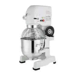
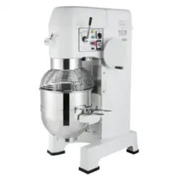
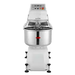
The LR-GM spiral mixer is a new type of kneader. Both the dough arm and bowl are running and this raises the mixing
speed and efficiency greatly. The machine is equipped with a protecting cover, safe and easy to operate. Overall, the
machine is good looking, easy to use and very efficient, suitable for food preparation in hotels, restaurants, food
processing factories and for material preparation in medicine making factories, chemical working facilities, etc.
2. FOREWORD
We reserve the right to alter the design of products without prior notice. While every effort is made to ensure that this
publication reflects the latest design, the company cannot guarantee full compliance.
2
3. GENERAL INFORMATION
The following information and instructions may not cover all details or variations in the equipment, nor cover every
problem that one may have during installation or use. If additional information is required, please contact us.
4. SAFETY INFORMATION
The following procedures and instructions should always be carried out in order to prevent injuries. If the machine is not
used as recommended, the operator will be responsible for his own safety and for the safety of other persons who may be
involved.
The information in this manual aims at assisting the operator to understand, maintain, and operate the mixer correctly. In
order to prevent accidents, please ensure to read, understand and follow all precautions and warnings contained in this
manual before installation or operating. To gain a clear understanding of your mixer, it is imperative to study this manual
carefully.
Rotating machinery and electricity are dangerous and may cause injuries if sufficient precautions are not taken prior to
operating or servicing the mixer. Ensure that the power supply is not connected to mixer and that it is isolated before
starting to clean or service the machine. In certain troubleshooting situations, it may be necessary to operate the mixer. In
such cases, extreme caution must be used. Only suitably qualified personnel must service the mixer.
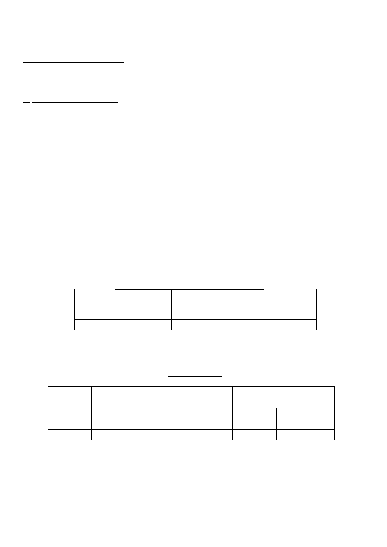
Technical specifications
Capacity Chart
Model
Bowl capacity
Dry Flour Capacity*
Kneading Dough Capacity*
LR GM25B
73 L
77 Qt.
15 kg
33 lbs
24 kg
53 lbs
LR GM50B
130 L
137 Qt.
30 kg
66 lbs
48 kg
106 lbs
LR GM75B
200 L
211 Qt.
40 kg
88 lbs
64 kg
141 lbs
*Capacities in the above chart refer to recommended batch loads for optimal machine
longevity. Calculations based on 60% AR (Hydration Ratio).
Model
Dimension (mm)
Voltage (V/Hz)
Power (kw)
Net weight (kg)
LR-GM-25B
990X575X1300H
220/60
2.6/3.5
230
LR-GM-50B
1100X700X1500H
220/60
4.1/5.6
400
LR-GM-75B
1332X950X1510H
220/60
6.1/11.1
650

3
4.1 SAFETY GUIDELINES
Ensure that sufficient precautions are observed when manually handling the mixer, particularly when moving the mixer
into position or installation. Ensure to comply with manual handling regulations.
• This appliance is only for commercial and not for domestic use.
• The mixer is not intended for use by children.
• While the machine is in operation, do not remove any cover.
• When mixing products that develop dust, extreme care must be taken.
• Exposure to dust (including flour) may be harmful to health, thus causing rhinitis (running nose), watering eyes and
possibly occupational asthma.
• If dust is a hazard, ensure that appropriate PPE (personal protective equipment) is used by operators, i.e., a mask.
• All operators must be trained in the safe operation of the mixer and attachments.
• This appliance is not to be used by anyone who with a lack of knowledge. Ensure that all operators have been
appropriately trained.
• This appliance is not intended to be used by those whose sensory, physical or mental capabilities prevent them from
being able to operate it safely.
• Ensure that the electrical supply has been isolated and the power cord disconnected before attempting to move or
service the mixer.
• Be aware of the start capacitor situated behind the rear motor cover. In normal circumstances this should discharge
when the mixer is switched off. In case of doubt, discharge the capacitor following adequate safety precautions.
• When accessing electrical components inside the mixer, be cautious of exposed conductors that could be 'live'.
• Always have your mixer and attachments regularly serviced, that is at least twice a year, depending on the frequency
of use.
• Ensure that this manual is kept in an easily accessible place near the mixer for future reference.
4.2. SAFETY INSTRUCTIONS
A FULLY TRAINED AND COMPETENT PERSON ONLY MUST USE THE ATTACHMENT AND/OR MIXER.
When maneuvering or lifting a bowl and its contents with a total weight in excess of 500 kg, a bowl truck must be used. As
far as reasonably possible, avoid tasks concerned with manual handling that involve a risk to health. This equipment should
only be stored in or transported through an environment with an ambient temperature above 5°C and below 55°C.
Note: The mixer must only be used to the purpose for which it was designed and in line with operating instructions. When
mixing ingredients, care must be taken to avoid the inhalation of dust particles e.g. flour. Reference should be made to
product supplier's data sheets to ensure adequate precautions and protections are taken. The following instructions must be
observed when operating the mixer.
4.3. NEVER
• Wear loose clothing that may become caught in the mixer while it is in operation.
• Attempt to reach into the bowl while it is mixing.
• Access rotating parts.
• Use excessive force when operating which could affect the stability of the mixer.
• Operate the mixer if parts are disassembled.
• Override the safety switches fitted to the mixer.
4
• Open the guard to stop the machine.
• Use the mixer in an unsafe condition.
• Operate the mixer or attachment if a fault develops or if the mixer is unsafe.
• Attempt to repair the appliance. A qualified technician must service the machine.
• Clean the mixer with scouring powder or a scouring pad.
• Clean aluminum agitators in a dishwasher.
• Inhale mixing ingredient dust particles.
4.4. ALWAYS
• Use the mixer as intended and in line with the operating instructions.
• Use the mixer in a well-lit area.
• Stop the mixer before adding more ingredients.
• Use the stop button to stop the machine.
• Disconnect the main electricity supply before cleaning the mixer.
• Clean the bowl and agitators after use.
• Clean the mixer using mild soap and water.
• Clean the mixer daily.
• Inspect the power cable and appliance regularly. If a fault is found, do not operate the mixer.
Disconnect the main electricity supply before cleaning the mixer.
4.5. LIABILITY
Installations and repairs which are not carried out by authorized technicians or the use of other than original spare parts,
and any technical alterations to the machine, may affect the warranty set out in the standard conditions of sale
ATTENTION! DO NOT hose or pressure clean this appliance. It is vital to follow the cleaning procedures detailed later in
section 7 of this manual.
5. Operation and notes:
5.1. Fixing the machine in place
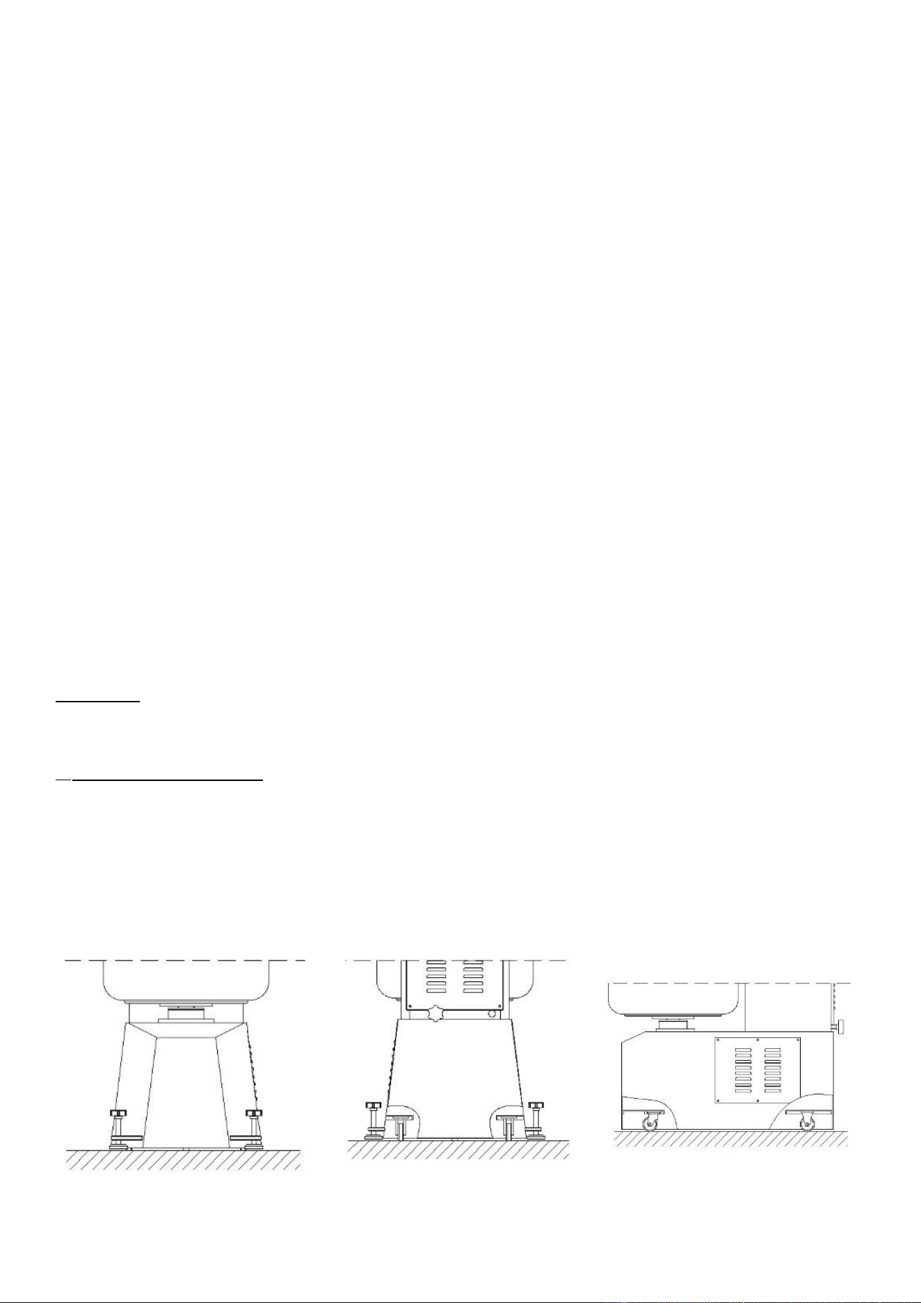
There are two directed casters, one mecanum wheel and a total of four regulating screws at the front and behind. (Pictures
1, 2, 3) After confirming the location of your machine, screw in the regulating screws to ensure the machine is held firmly
in place.
Pic1 Pic 2 Pic 3
5
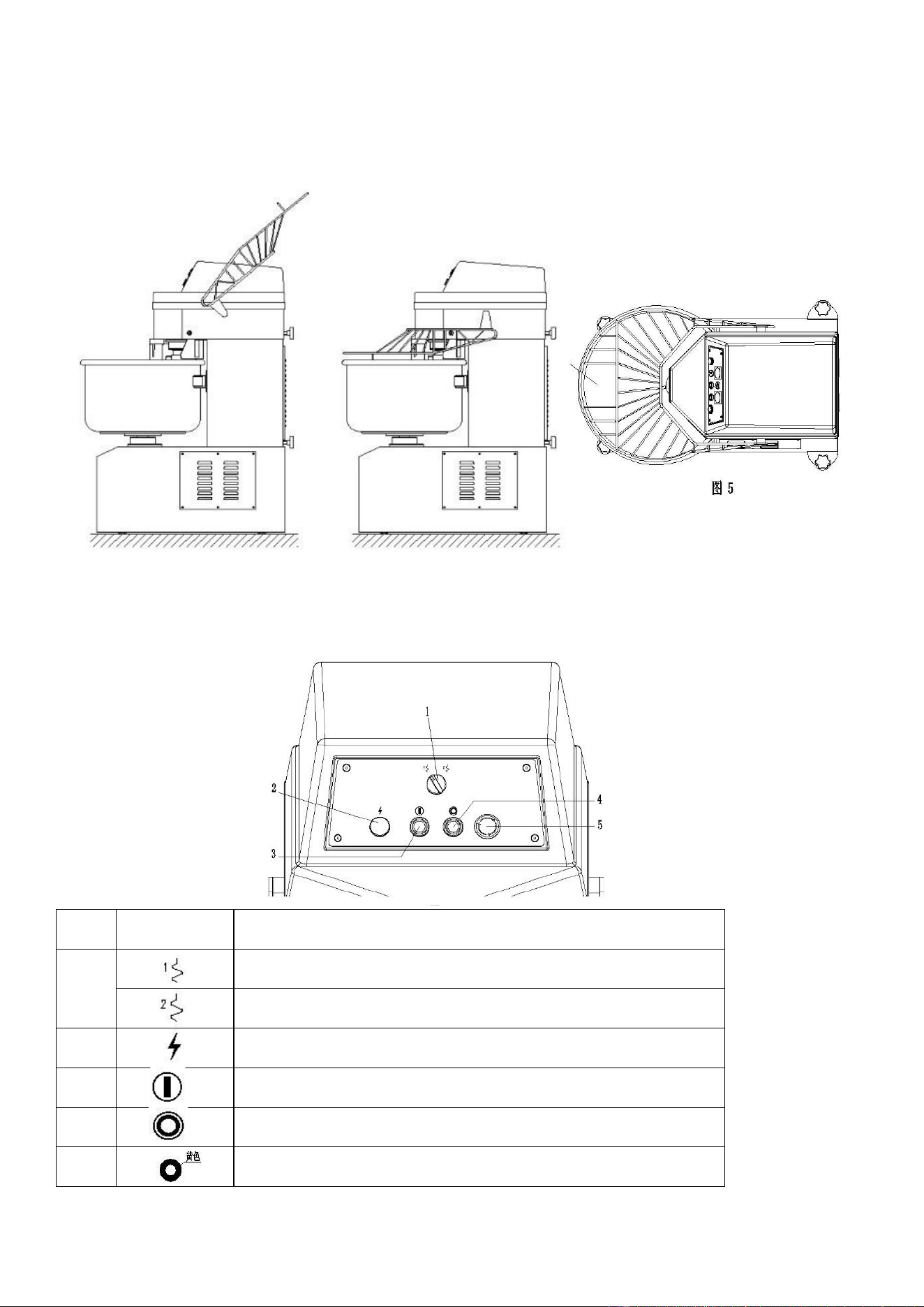
Spiral Cover for Operating Area
Before operating the machine, the spiral cover should first be placed over the operating area. There is a small hole in the
protective net, which can be used to get dough samples while the machine is not in operation. (Pictures 4, 5)
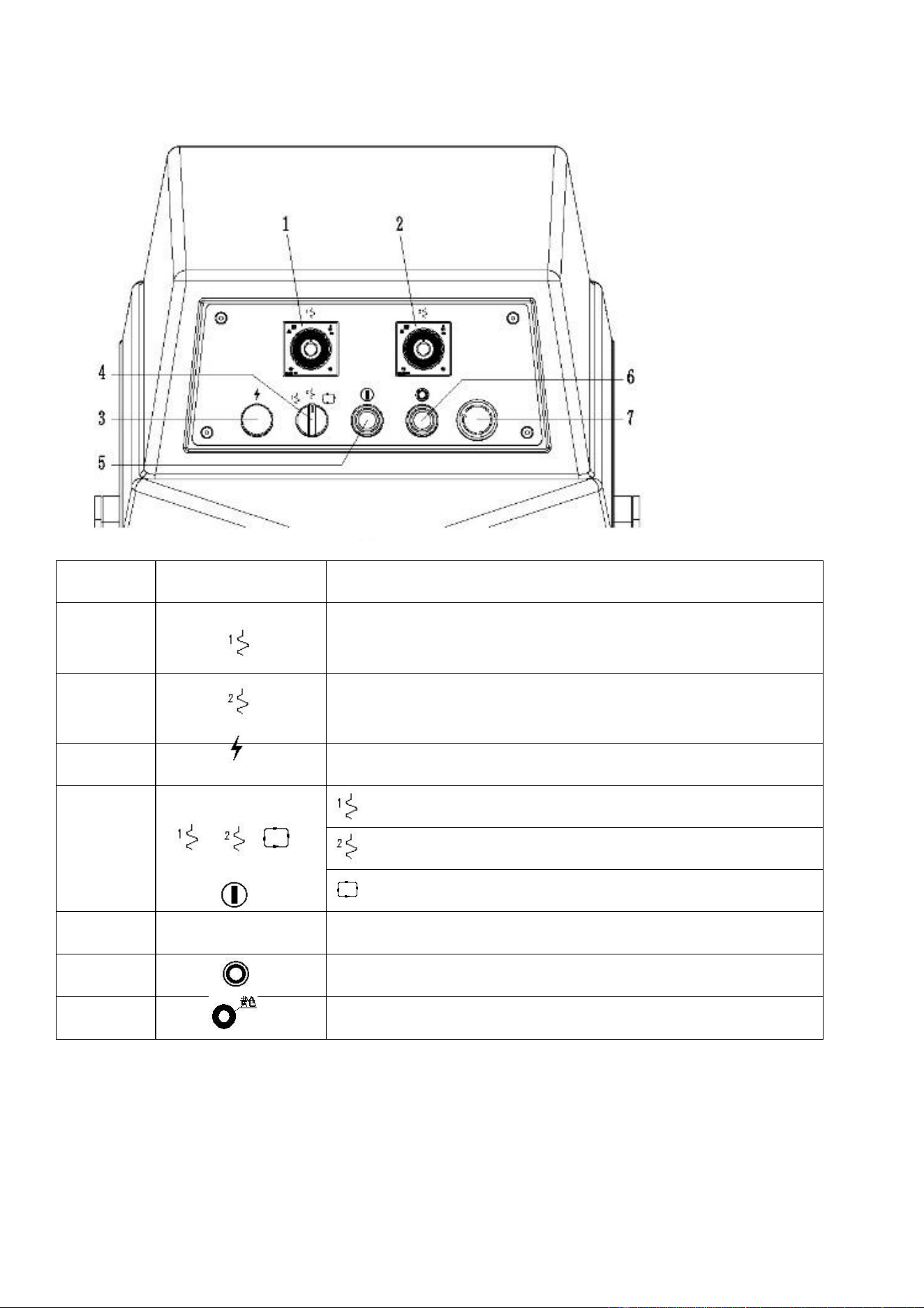
5.2 Control Panel
A. LR-GM-10
Numb
Sign
Introduction
1
Low speed in manual mode
High speed in manual mode
2
Power light indicator
3
Start button
4
Stop button
5
Urgent button (to scram)
6
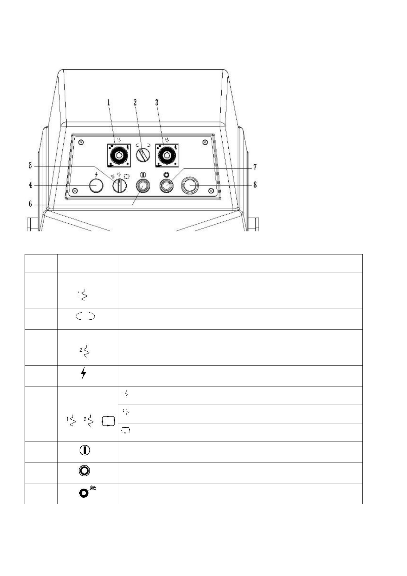
B. LR-GM-15, LR-GM-25
Number
Sign
Introduction
1
Controls duration of low-speed operation (used when an automatic
operated program is chosen)
2
Controls duration of high-speed operation (used when an automatic
operated program is chosen)
3
Power light indicator
4
Low speed in manual mode
High speed in manual mode
Setting programs for automatic operation
5
Start button
6
Stop button
7
Urgent button (to scram)
7
C. M-25B, LR-GM-50B, LR-GM-75B
Number
Sign
Introduction
1
Controls length of low-speed operation (used when an automatic operated
program is chosen)
2
Changes the rotary direction of the bowl
3
Controls length of the high-speed operation (used when an automatic operated
program is chosen)
4
Power light indicator
5
Low speed in manual mode
High speed in manual mode
Setting programs for automatic operation
6
Start button
7
Stop button
8
Urgent button (to scram)
8
“
”
5.3 Before Use
Make the following checks before operating the machine:
1.Check the input power and ensure it corresponds with the information on your machine.
2.Make sure that the rotary direction of the bowl is in the one indicated on the bowl.
3.Make sure that the protective cover is lying down correctly, as the power will shut down automatically if its angle is 30
degrees upwards or greater.
5.4 Setting up Machine Operation
Using the two timers, set the duration of the low and high-speed operation. For the low and high speeds, the duration can
be adjusted up to a maximum of 120 seconds.
1. After putting the raw materials and burdening into the bowl, place the protective cover over the bowl.
Notice:LR-GM-10, the flour mixing capacity is not more than 10 kg;
LR-GM-15, the flour mixing capacity is not more than 15 kg;
LR-GM-25,25B, the flour mixing capacity is not more than 25 kg;
LR-GM-50B, the flour mixing capacity is not more than 50 kg;
LR-GM-75B, the flour mixing capacity is not more than 75 kg
If the flour is used to mix steamed bread, noodles and other flour-based products, the spiral mixer can only mix 80% of the
listed maximum mixing capacity.
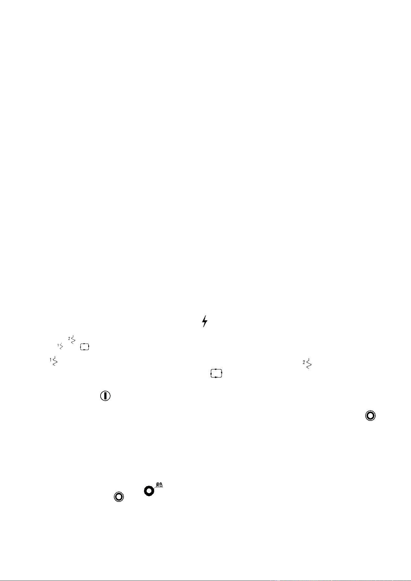
2. When the power is switched on, the power light indicator“ ” will turn on.
3.
Use the“ ” buttons to choose between manual and automatic operation.
When “ “ has been chosen, the machine will operate only at low speed until stopped. When ” has been chosen, the
machine will only operate at high speed until stopped. When “ ” has been chosen, the machine will operate at low
speed for the time set, and then at high speed for the time set and stop operating.
4. Press the start button “ ”. The bowl and spiral arm will rotate according to the direction shown by an arrow on the
bowl. Once it’s done, press the stop button to stop the operation. If the direction is wrong, press the stop button“ ,
and then to find an eligible electrician to exchange two-phase power.
Warning: Don’t load the bowl over the specified capacity limit. Otherwise serious damage to your machine may occur.
5. In emergency conditions, while the machine is operating, you can shut down the machine using the following methods:
Shut off the power, and let the power button point at“0”;
Press the button to turn off“
”;
9
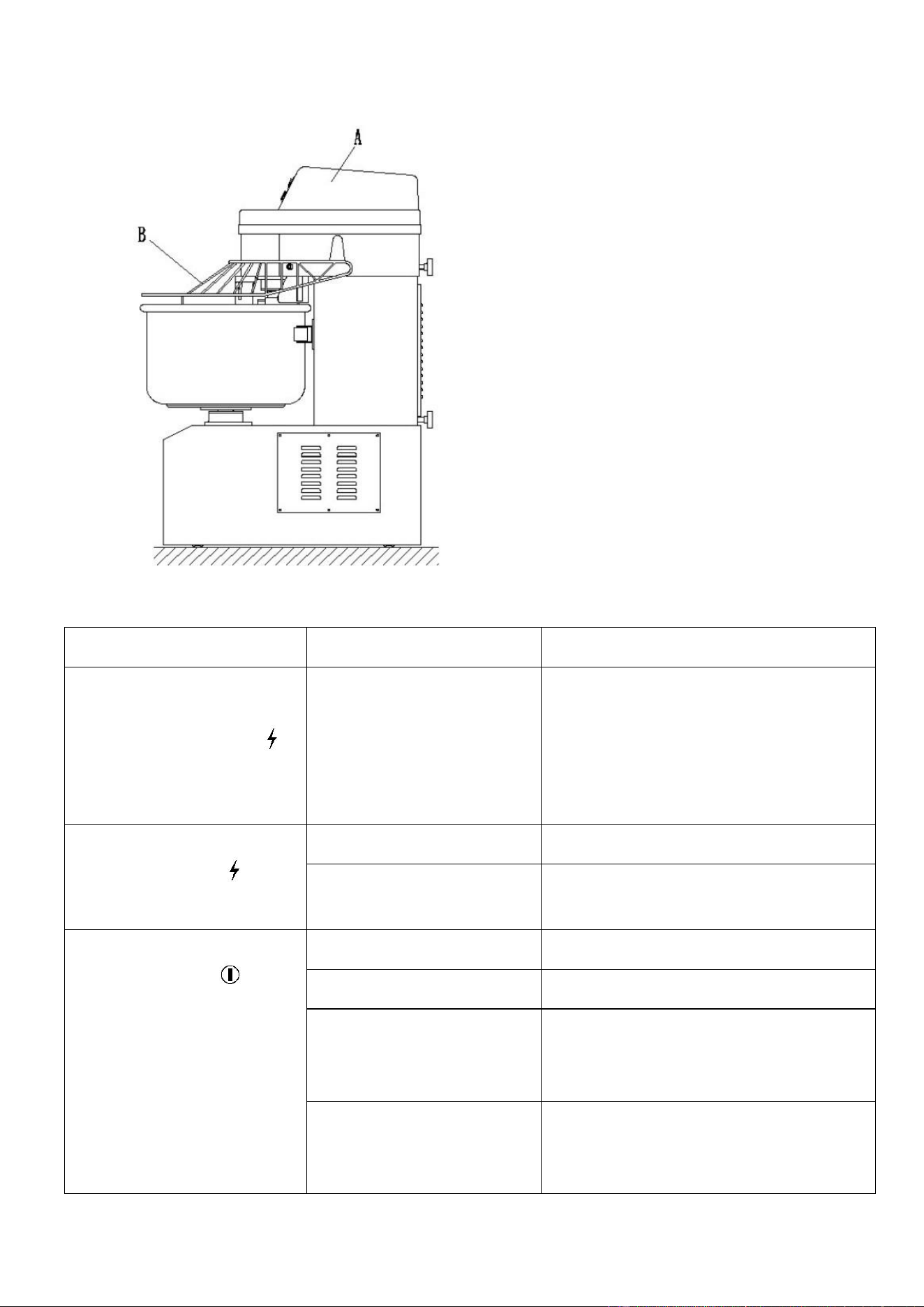
5.5 Faults and Fixes
In order to find and fix faults, please refer the Picture 9 and chart:
Pic.9
5.6 Fault analysis:
Operating fault
Possible cause
Possible solution
While the machine is in
operation, it suddenly stops
working, and indicator light “ ”
continues to flash.
The bowl has been loaded over
its capacity limit.
Turn off the power, and open cover “A” for the
electric box. Press the reset button and then
take out the excess capacity. If after these
steps, the machine is still not operating, please
contact the service department.
Switching on the power and the
power light indicator “ “ on the
control panel does not light up.
The indicator bulb has burnt out.
Change the bulb.
The power line for the light has
been disconnected.
Check the power line for any disconnections
and reconnect.
The machine does not start
operating when the “ ”button is
pressed.
The start button is broken.
Check and replace broken parts.
The stop button is broken.
Loosen the urgent button (rotate clockwise).
The urgent button is not
resetting or protective cover “B”
is not positioned correctly.
Lay down the protective cover.
When the automatic program is
chosen but the time for second
speed is still in the “0”.
Reset the program.

10
5.7 Important Checks to make before Maintenance
In order to follow the right procedure and prolong the service life of the spiral mixer, please comply with these professional
checks as follows.
5.8 Important warnings
All operations concerning maintenance must only take place after the power has been turned off.
Do not clean, lubricate or add oil while the machine is operating.
Do not correct any fix any problems or adjust any parts while the machine is operating.
Appropriate warnings have been made and requested for here and in the introduction, so our company will not be liable for
any actions that result in harm to people or animals.
5.9 General Maintenance and Inspection
Perform the following checks to ensure that the machine stays in working condition.
Every day: (1) Visually check the machine to see if it is still operating well.
(2) Check if the ground wire is safe.
Every two months: Adjust conveyor tension. (Refer to instructions on the following page.)
After use, clean the bowl with clean water and dry thoroughly to avoid short circuits.
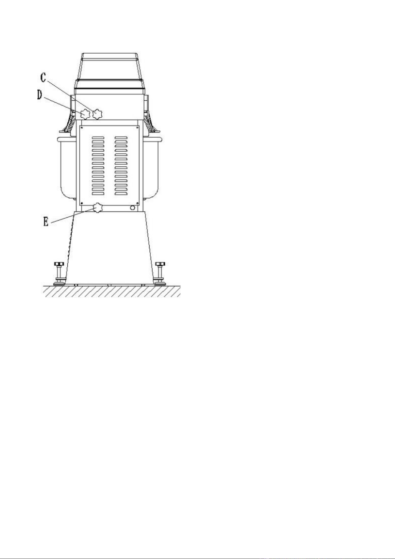
How to Adjust Conveyor Pulls
1. To adjust bucket pull: check the pull of belts, and use the rotary button to start final adjustments.
2. To adjust mixing lever pull: check the pull of the top belt, first to adjust knob E, and then knobs C and D. (Adjust
degree of tightness according to the arrow next to the rotary button.)
11
Pic.10
5.10 Professional Maintenance and Inspection
Because these inspections are complex, they require a company or technician who has the professional qualifications
needed to perform this job.
When required, change parts which are broken. Inspect and adjust the inside of the machine to ensure that it is safe.
When the cable insulation has broken, it should be replaced immediately.
Every year, the machine should be inspected and maintenance performed if required, changing and adjusting any sections
which may be broken to ensure safe design and operation.
To check electricity and insulation safety, perform continuous checks to ensure that the circuit is operating correctly and
safely.
Notice: If any parts need to be changed, you can only use original manufacturer’s parts.
Urgent situations:
To ensure the safe operation of the machine, the user should know what to do in case of emergency. Do not clean or
maintain until the user remembers these steps.

12
A. If the machine seems to be under the risk of being damaged, press the scram button and turn off the power. Then
inspect carefully to find the reason for the fault. Once you find the problem, reset the machine and prepare for the safe
operation of the machine. If necessary, find a competent technician capable to help.
B. If an electric leak occurs when touching a metal part of the machine, check ground wire to verify if it is connected or
not, or check the machine if it is.
6. INSTALLATION
A qualified person must install this machine in accordance with current regulations
6.1. UNPACKING AND HANDLING
Wherever possible, the mixer should be transported to the installation position inside its packaging to avoid any damage.
Do not use a sharp knife to open the box to prevent damaging the machine. Upon the first inspection, check for any
possible shipping damages. If any damage is found, save the packaging material and contact us.
Caution: The mixer is heavy and must be correctly handled and lifted to avoid personal injuries.
When the machine is in the vicinity of its final position, remove from the transportation pallet. The machine is fastened to
the pallet with four retaining bolts reaching into threaded feet of the base. Care must be taken during this operation to
ensure:
• All required safety measures are taken to ensure correct lifting and handling to avoid risk of injury, which may be
through dropping, falling or tilting.
• No damage is done to the machine which could impair its normal operation.
6.2. LOCATION
The mixer is not suitable for outdoor installation and must not be installed where a water jet could be used for cleaning.
The mixer must only be operated by trained staff and must be installed in an area where the use and maintenance are
restricted to trained personnel.
Ensure that the mixer is at a height with the bowl handles approximately between knuckle and elbow height. This will
reduce the need to bend at waist level.
Select a suitable flat level surface that can support the weight of the mixer and bowl contents when full. It is
recommended to secure the mixer in position. Ensure the table, stand or work surface is firmly fixed to the floor. The
appliance must be restrained to prevent any movement during use.
Ensure that there is sufficient space around the mixer to ensure the safe operation. Servicing may also become an issue if
there is a greatly reduced clearance. For this reason, ensure that service access on the top, side and rear of the mixer are
clear.
6.3. ELECTRICAL INSTALLATION.
The electrical installation of the mixer must comply with the local or national electricity board regulations.
A competent person must carry out the electrical installation. Ensure that the electrical supply agrees with machine
specifications prior to connecting it.
The mixer is a Class l appliance, since the protection against electric shock does not rely solely on basic insulation. An
external electrical isolator and MCB/fuses (both supplied by others) must be fitted to the incoming electrical supply of the
13
mixer. In addition, a 35-mA residual current device is strongly recommended to provide extra protection.
“This appliance should be connected to a supply source with an impedance value Zsys less than (0.05+j0.03) Ω.
If the supply cord is damaged, it must be replaced with a special cord or assembly available from the manufacturer or its
service agent.”
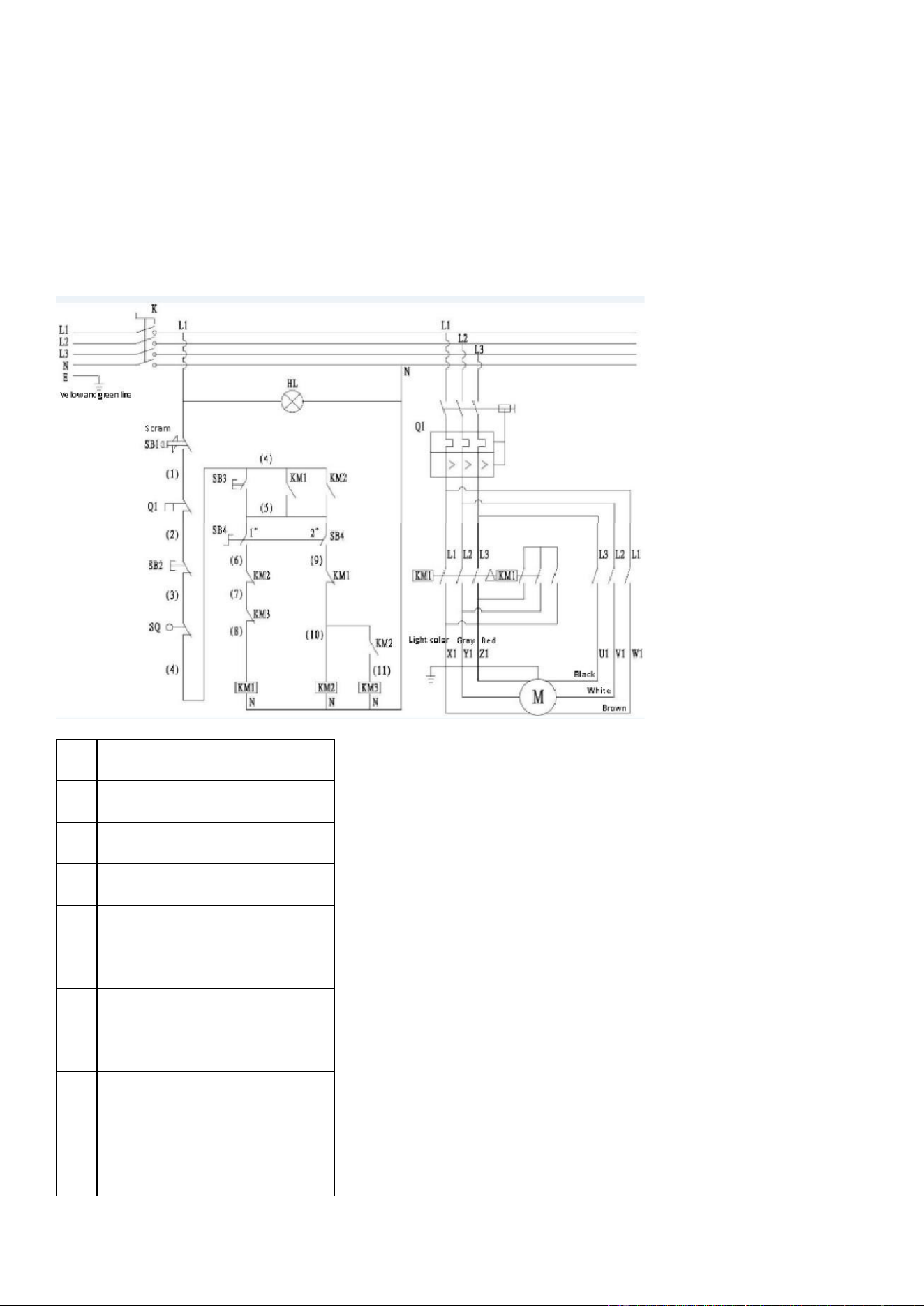
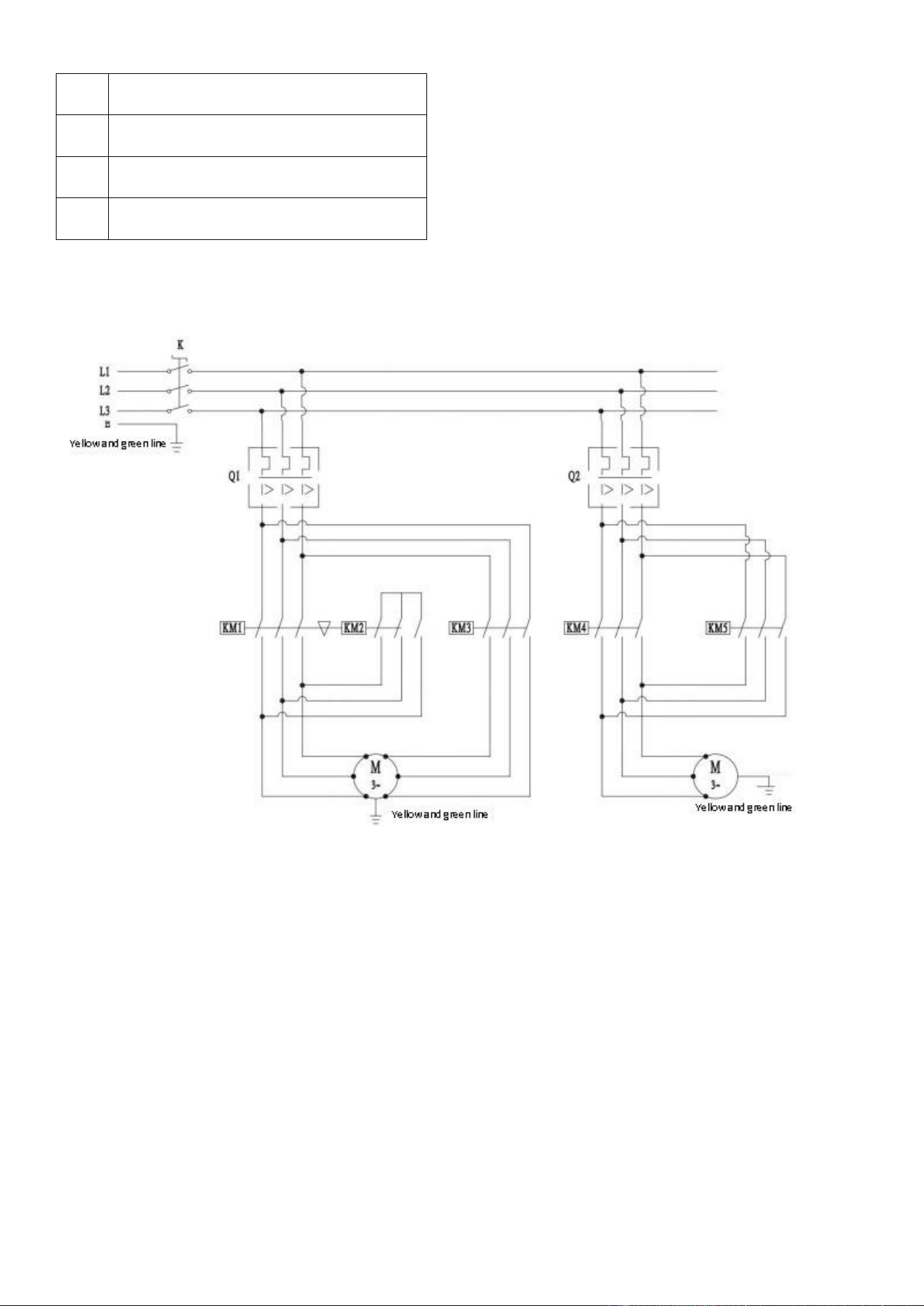
LR-GM-10 Circuit
(1)
K Three-phase four wire air switch
(2)
SB1 Abrupt stop switch
(3)
SB2 Stop switch
(4)
SQ Travel switch
(5)
SB3 Start switch
(6)
SB4 Second gear selector switch
(7)
KM1 Slow contactor
(8)
KM2, KM3 Rapid contactor
(9)
Q1 Motor protection
(10)
M Motor
(11)
HL Power light
14
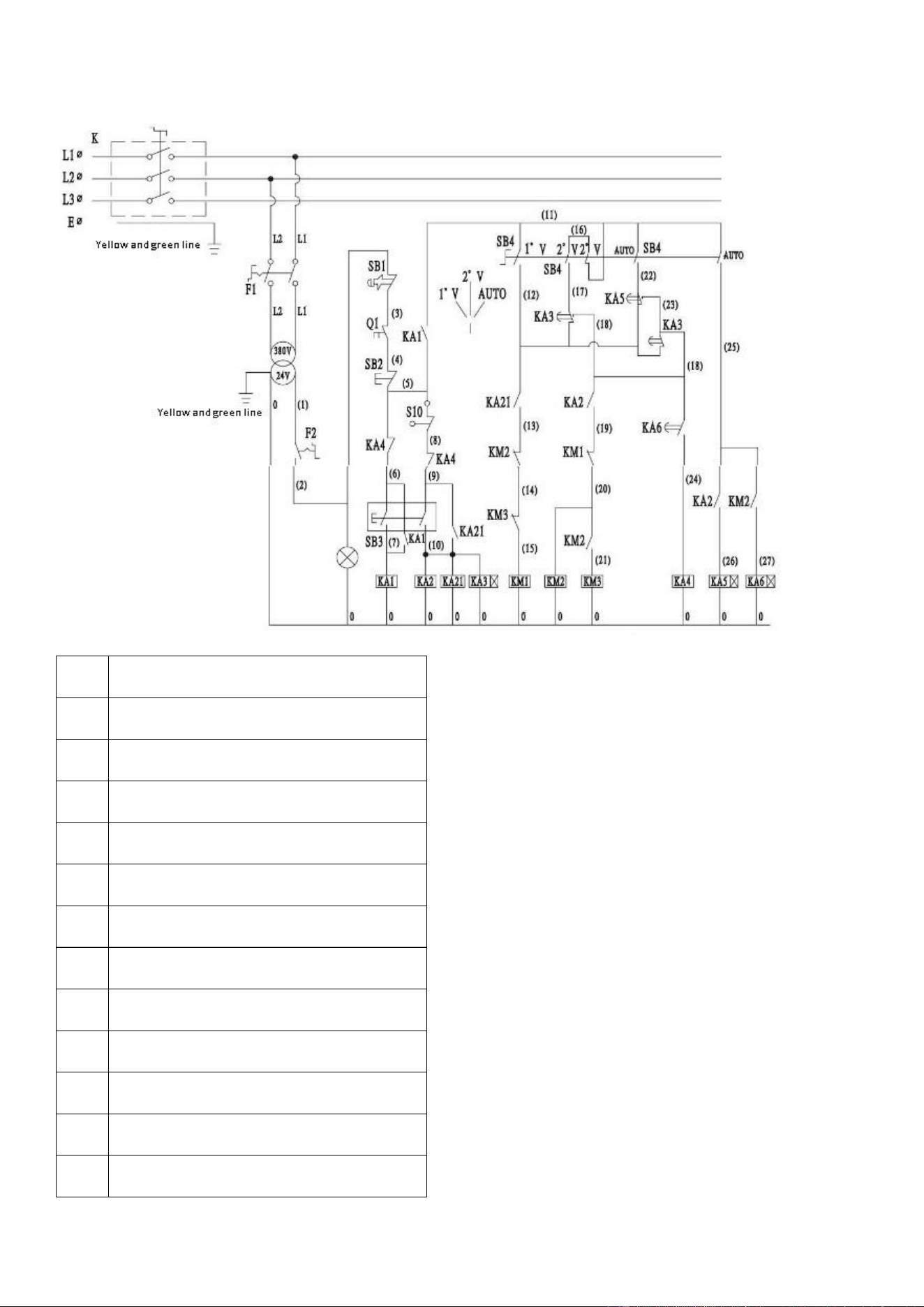
LR-GM-15,25Circuit
(1)
K Three-phase air switch
(2)
Q Three-phase motor protection switch
(3)
M Motor
(4)
F1 Two air switch
(5)
F2 Air switch
(6)
SB1 Abrupt stop switch
(7)
SB2 Stop switch
(8)
SB3 Start switch
(9)
SB4 Selected switch
(10)
T Variable air
(11)
S10 Travel switch
(12)
HL Power light
(13)
KA1, KA2, KA21, KA4 Relay
15
(14)
KA3 6-second time relay
(15)
KA5, KA6 Automatic transmission time relay
(16)
KM1, KM2, KM3 AC contactor
(17)
Q1 Three-phase motor protection switch
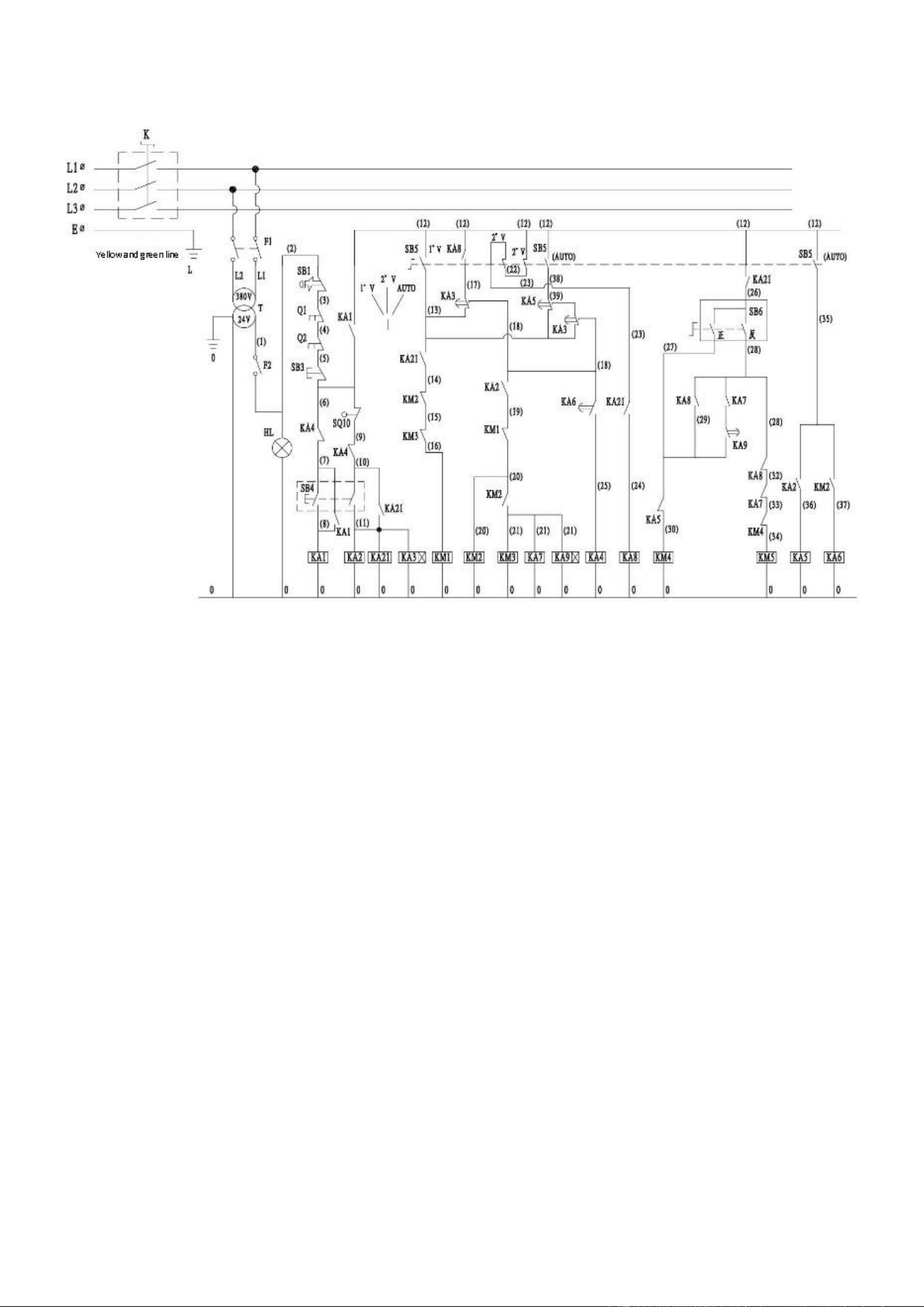
LR-GM-25BCircuit
16
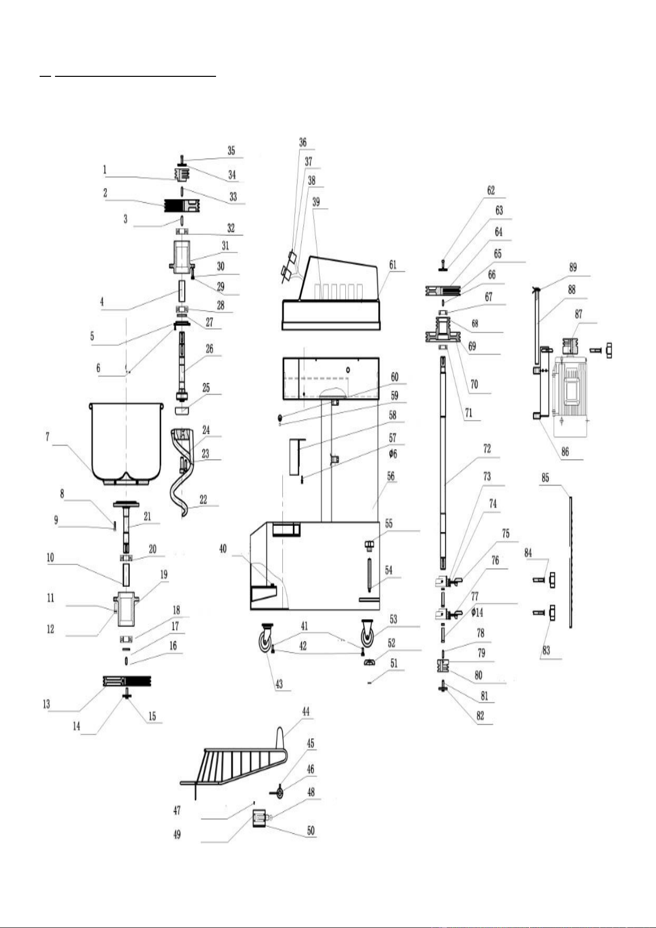
LR-GM-50BCircuit
17
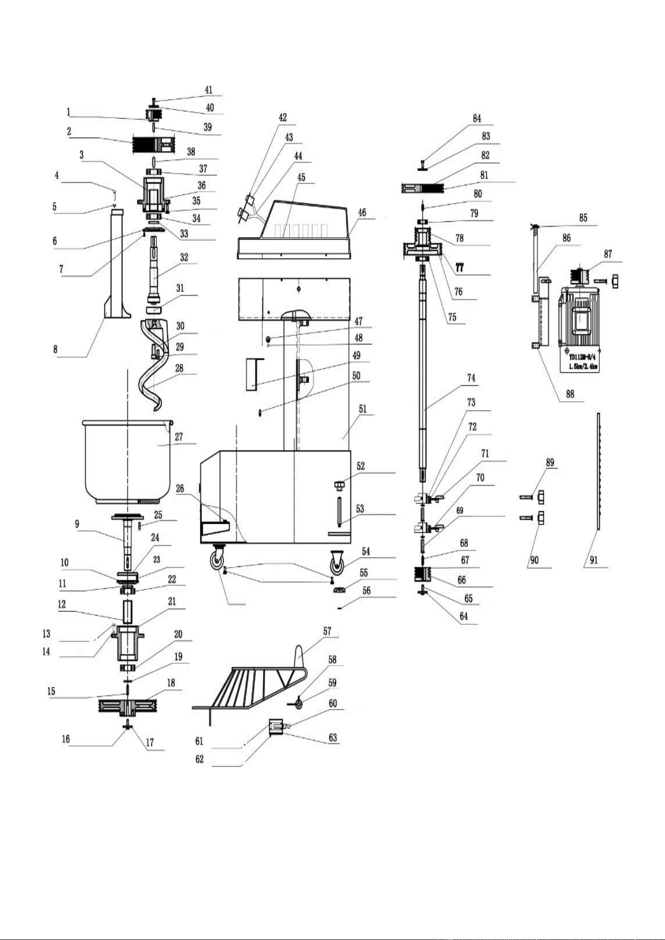
7. MACHINE ILLUSTRATION:
LR-GM-10
18
No.
Name
No.
Name
No.
Name
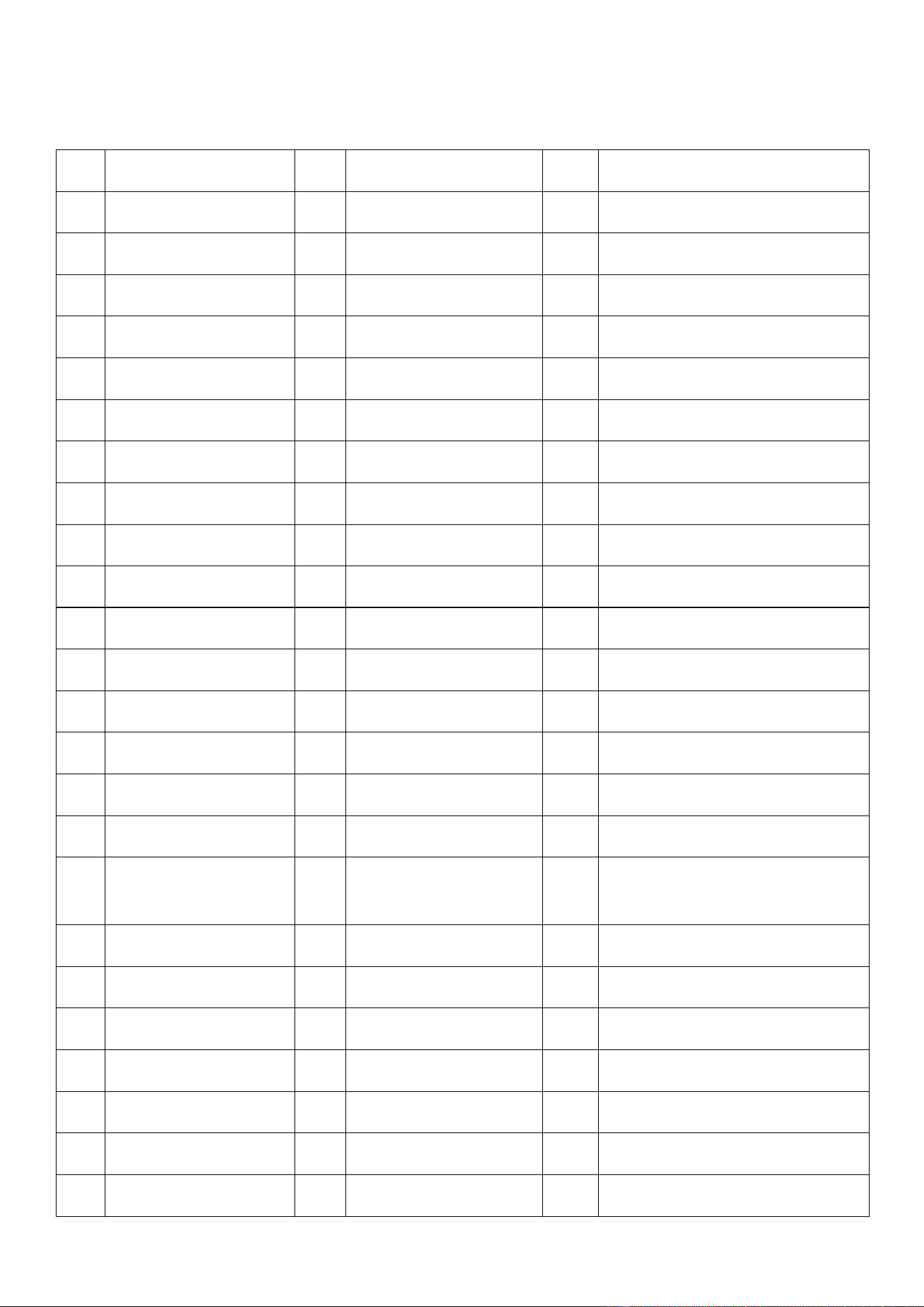
1
Spindle drive belt pulley
31
Upper bearing seat
61
ABS cover
2
Upper shaft pulley
32
6308 bearing
62
M8-20 screw
3
10-32 square key
33
8-32 square key
63
Gaskets
4
On the sleeve
34
Gaskets
64
Main shaft pulley
5
Bearing cover
35
M8-20 screw
65
V-type narrow belt SPZ787LW
6
4-M5 screw
36
Control panel
66
8-25 square key
7
Surface barrel assembly
37
Electrical components
67
6205 bearing
8
M8-25 screw
38
Wire
68
V-type narrow belt SPZ787LW
9
Φ8 flat pad elastic pad
39
Electric plate
69
V-type narrow belt SPZ787LW
10
Shaft
40
M8 nut
70
On the secondary shaft skin belt
11
4- with Φ10 elastic flat pad
41
M8-20 screw
71
6027 bearing
12
4-M10-30 screw
42
Playing the flat pad
72
Spindle drive belt pulley
13
Drum belt pulley
43
Casters
73
Uc207 ball bearing
14
Gaskets
44
Stainless steel mesh cover
74
Bearing seat
15
M10-30 screw
45
M6 stud
75
Adjusting screw
16
10-40 square key
46
46 stroke switch sleeve
76
Pull plate
17
Adjustment pad
47
2-m6 cross screw
77
M14-45 screws, nuts, washers, flat pad
diameter 10
18
6308 bearing
48
Stroke switch
78
8-35 square key
19
Lower bearing seat
49
4-m5 cross screw
79
Barrels to stimulate the belt pulley
20
6308 bearing
50
Stroke switch seat
80
V type narrow belt spz1140lw
21
Lower axis
51
Card spring
81
M10 screw
22
Spiral groove
52
Anchor support plate
82
Gaskets
23
M10-30 screw
53
Fixed wheels
83
Pull rod handle
24
M16-40 screw
54
Foot adjusting bolt
84
2- with 10 flat pad

19
25
On the dust cover
55
Foot plum handle
85
Maintenance door
26
Upper shaft pulley
56
Casing welded parts
86
Motor seat components
27
Sealing ring
57
M6-20 screw
87
Motor belt pulley
28
6308 bearing
58
Baffle unit
88
Motor positioning shaft
29
M10-30 screw
59
M8-20 screw
89
Motor positioning shaft
30
Φ10 elastic flat pad
60
Net cover lever
20
LR-GM-15
21
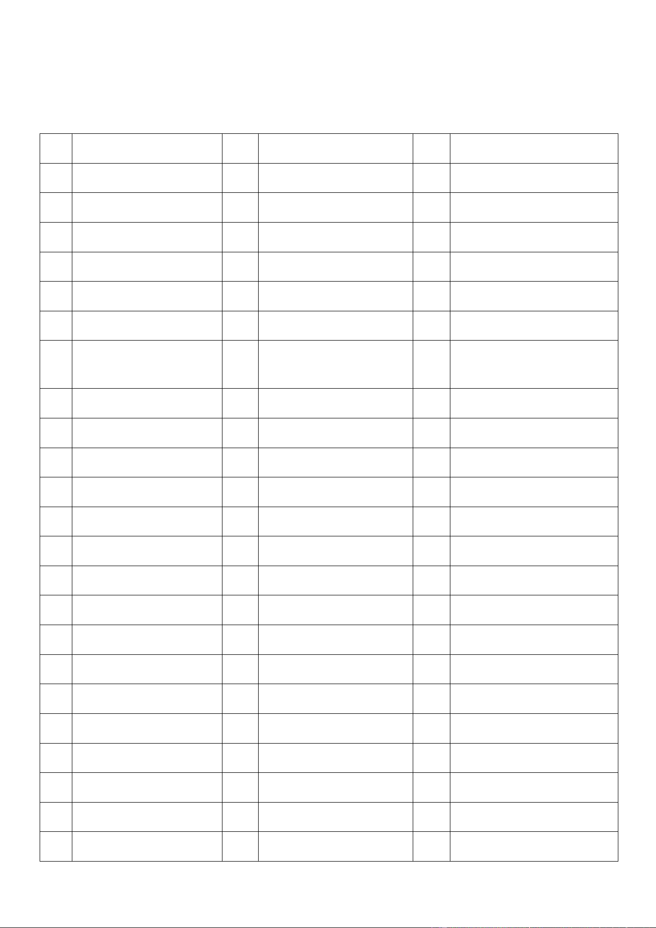
No.
Name
No.
Name
No.
Name
1
Spindle drive belt pulley
32
Upper shaft
63
Stroke switch seat
2
Upper shaft pulley
33
Sealing ring
64
Gaskets
3
On the sleeve
34
6308 bearing
65
M10 screw
4
M8-40 screw
35
M10-30 screw
66
V-type narrow belt 3V530
5
M8 nut
36
Bearing seat
67
Barrels of secondary belt pulley
6
Bearing cover
37
6803 bearing
68
8-35 square key
7
M5 screw
38
10-40 square key
69
M14-45 screws, nuts, washers, flat
pad diameter 14
8
Center pole
39
8-35 square key
70
Pull plate
9
Lower axis
40
Gaskets
71
Adjusting screw
10
Bearing cover
41
M8-20 screw
72
Bearing seat
11
Sealing ring
42
Control panel
73
Uc207 ball bearing
12
Shaft
43
Electrical components
74
Spindle
13
Φ10 elastic flat pad
44
Conductor
75
6207 bearing
14
M10-30 screw
45
Electric plate
76
Upper shaft secondary belt
15
10-40 square key
46
Abs cover
77
V-type narrow belt spz812lw
16
M10-30 screw
47
Net cover lever
78
V-type narrow belt 3V335
17
Gaskets
48
M8 screw
79
6205 bearing
18
Drum belt pulley
49
Baffle unit
80
8-25 square key
19
Adjusting washer
50
M6-20 screw
81
V-type narrow belt 3v335
20
6308 bearing
51
Casing welded parts
82
Main shaft pulley
21
Lower bearing seat
52
Anchor hold plum disc
83
Gaskets
22
6308 bearing
53
Foot adjusting bolt
84
M8-20 screw
23
M5-10 cross screw
54
Fixed wheels
85
Motor positioning sheath

22
24
Lower dust cover
55
Anchor support plate
86
Motor positioning shaft
25
M8-25 screw
56
Card spring
87
Motor belt pulley
26
M8 nut
57
Stainless steel mesh cover
88
Motor seat components
27
Surface barrel assembly
58
M6 stud
89
Φ10 flat pad
28
Screw hook
59
Stroke switch sleeve
90
Pull rod
29
M10-30 screw
60
Stroke switch
91
Maintenance door
30
Φ10 elastic flat pad
61
M5 cross screw
31
On the dust cover
62
M6 cross screw
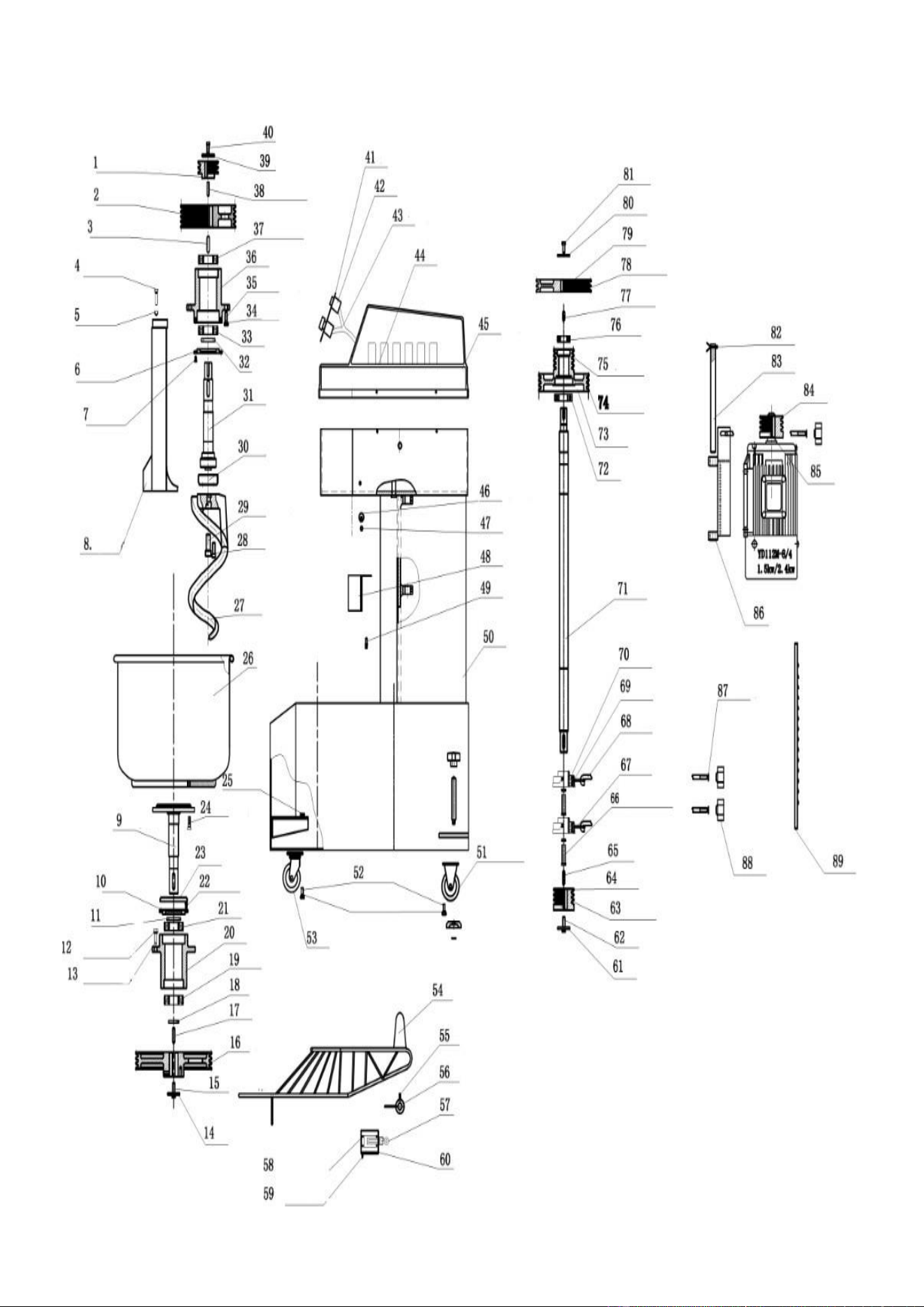
23
LR-GM-25
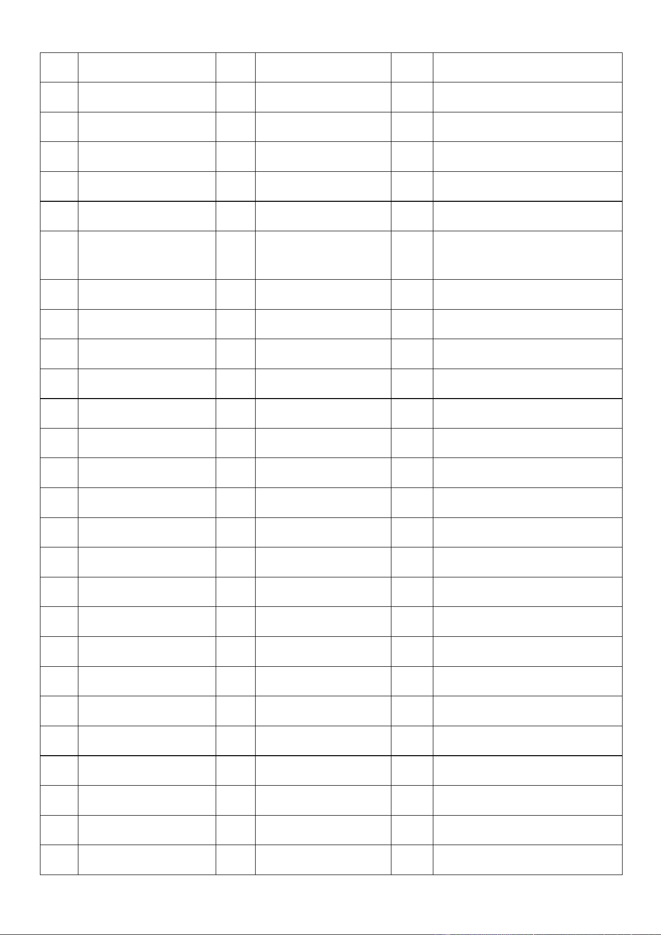
24
No.
Name
No.
Name
No.
Name
1
Drive spindle belt pulley
31
Upper shaft
61
Gaskets
2
Upper shaft belt pulley
32
Sealing ring
62
M10 Screw
3
10-40 square key
33
6308 bearing
63
V-type narrow belt spz1140lw
4
M8-40 screw
34
Phi 10 flat elastic pad
64
Barrels secondary belt pulley
5
M8 nut
35
M10-30 Screw
65
8-35 square key
6
Cover bearing
36
Upper bearing seat
66
M14 x 45 screw, nut, φ 14 spring
washers, flat pad
7
M5 screw
37
6803 bearing
67
Plate pull
8
Pole center
38
10-40 square key
68
Adjusting screw
9
Lower axis
39
Gasket
69
Bearing seat
10
Cover bearing
40
M8-20 screw
70
Uc207 ball bearing
11
Sealing ring
41
Control panel
71
Spindle
12
Phi 10 flat elastic pad
42
Electrical components
72
6207 bearing
13
M10-30 screw
43
Wire
73
Shaft upper secondary belt
14
Gaskets
44
Electric plate
74
V-type narrow belt spz812lw
15
M10-30 screw
45
ABS cover
75
V-type narrow belt spz850lw
16
Belt pulley drum
46
Cover lever net
76
6205 bearing
17
10-40 square key
47
M8-20 screw
77
8-25 square key
18
Adjusting washer
48
Baffle
78
V-type narrow belt spz850lw
19
Adjusting washer
49
M6-20 screw
79
Main pulley shaft
20
Lower bearing seat
50
Welded part casing
80
Gasket
21
6308 bearing
51
Fixed wheels
81
M8-20 screw
22
M5-10 cross screw
52
M8-20 screw
82
Positioning sheath motor
23
Dust cover lower
53
Casters
83
Positioning shaft motor
24
M8-25 screw
54
Fixed wheels
84
Belt pulley motor
25
M8 nut
55
Steel stainless mesh cover
85
Inner six stud angle
26
Surface and barrel assembly
56
Switch sleeve stroke
86
Seat components motor

25
27
Hook screw
57
Switch stroke
87
Phi 10 pad flat
28
M16-40 screw
58
M5 cross screw
88
Blossom handle plum
29
Phi 10 flat elastic pad
59
M6 cross screw
89
Door maintenance
30
Dust cover
60
Switch seat stroke
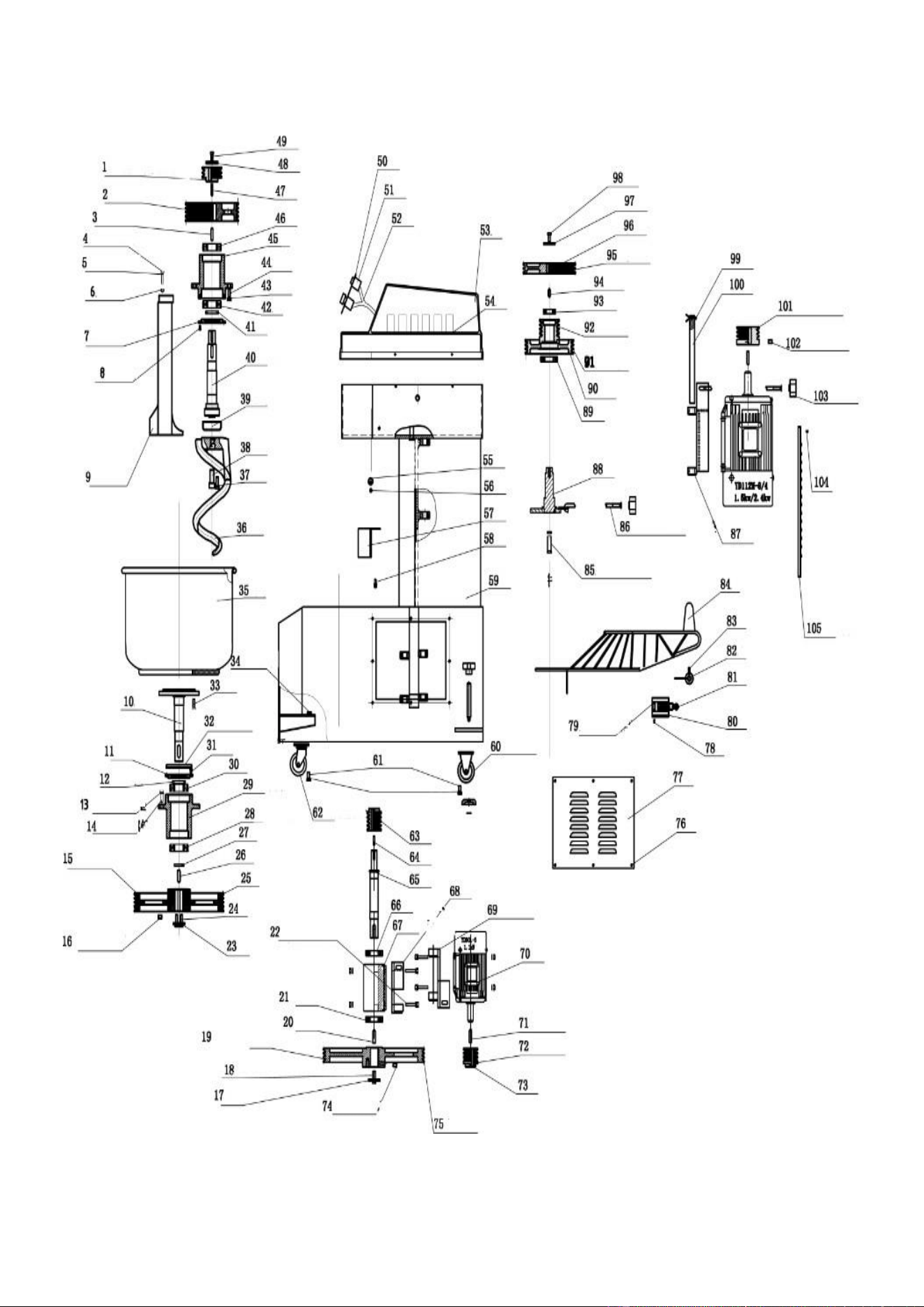
26
LR-GM-25B
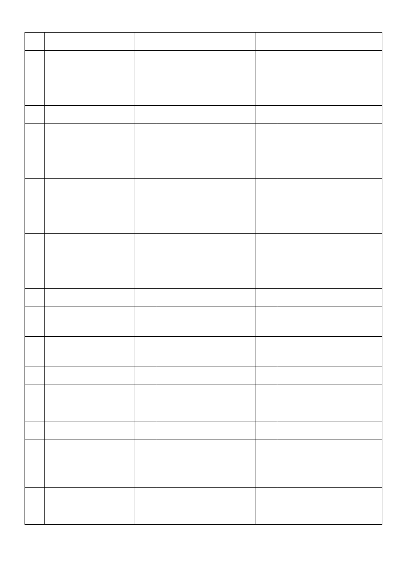
27
No.
Name
No.
Name
No.
Name
1
Main shaft driving pulley
36
Screw hook
71
10-40 square key
2
Shaft pulley
37
M10-30 screw
72
Motor pulley base
3
10-40 square key
38
M16-40 screw
73
Socket head screw
4
M8-40 screw
39
Petition dust cover
74
M10-30 screw
5
8 ball pad Φ flat pad
40
Shaft
75
Narrow V-belt SPZ1437LW
6
M8 nut
41
Sealing ring
76
M6 screw
7
Bearing cover
42
6308 bearing
77
Base to repair the door
8
M5 screw
43
M10-30 screw
78
M6 screw
9
Center pole
44
Φ 10 spring washer flat pad
79
M5 cross screws
10
Shaft under
45
On the bearing seat
80
Stroke switch
11
Bearing cover
46
6308 bearing
81
Travel switch
12
Sealing ring
47
8-35 square key
82
Trip switch shaft sleeve
13
Φ 10 spring washer flat pad
48
Gasket
83
M6 screw
14
M10-30 screw
49
M8-20 screw
84
Stainless steel net
15
Narrow V-belt SPZ1270LW
50
Control panel
85
M14-45 screw, nut, Φ 14 spring
washers, flat pad
16
M10-30 screw
51
Electrical components
86
Adjusting screw, Φ 10 flat mat
plum flower handles
17
Gasket
52
Conductor
87
Motor parts
18
M10-30 screw
53
ABS cover
88
On the spindle
19
Spindle pulley
54
Electric appliance plate
89
6207 bearing
20
Bearing
55
Net gearbox
90
Secondary pulley shaft
21
6307 bearing
56
M8-20 screw
91
narrow V-belt spz812lw
22
M8-45 screw, nut, Φ 8 spring
washers, flat pad
57
Baffle
92
Narrow V-belt SPZ850LW
23
Gasket
58
M6-20 screw φ 6 flat pad
93
6205 bearing
24
M10-45 screw
59
Chassis weldment
94
8-25 square key
28
25
Pulley barrel
60
Fixed caster
95
Narrow V-belt spz850lw
26
10-40 square key
61
M8-20 screws
96
Main shaft pulley
27
Adjust the washer
62
Casters
97
Gasket
28
28.6308 bearing
63
Spindle pulley
98
M8-20 screws
29
Bearing seat
64
6-30 square key
99
Motor positioning sheath
30
6308 bearing
65
Main shaft
100
Motor positioning sheath
31
M5-10 cross screws
66
6307 bearing
101
Motor pulley
32
Dust cover
67
Bearing sleeve
102
M10-15 stud
33
M8-25 screw
68
Bearing sleeve
103
Plum flower handles
34
M8 nut
69
Motor base
104
M6 screw
35
Barrel assembly
70
M10-30 screw
105
Fuselage to repair the door
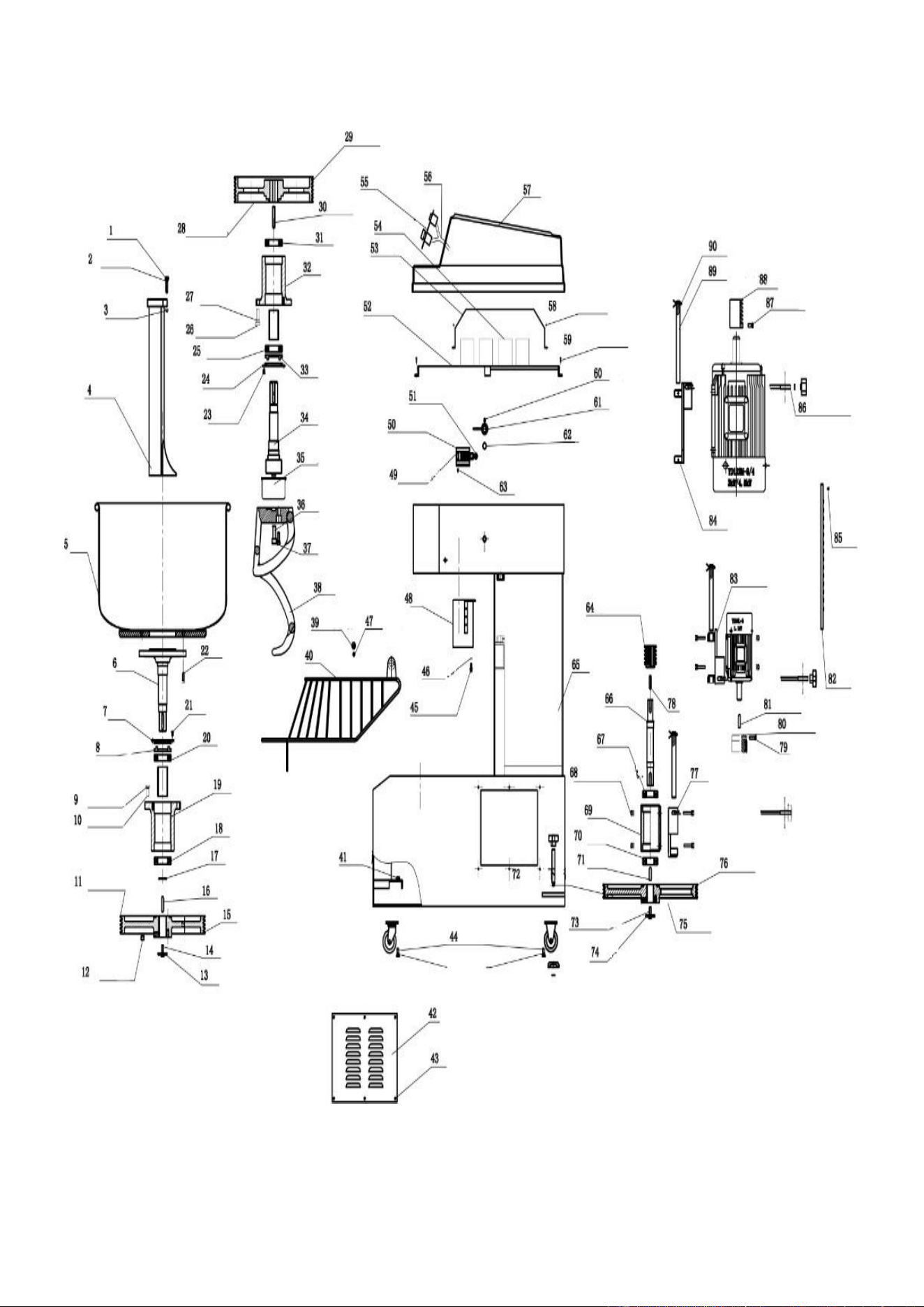
29
LR-GM-50B
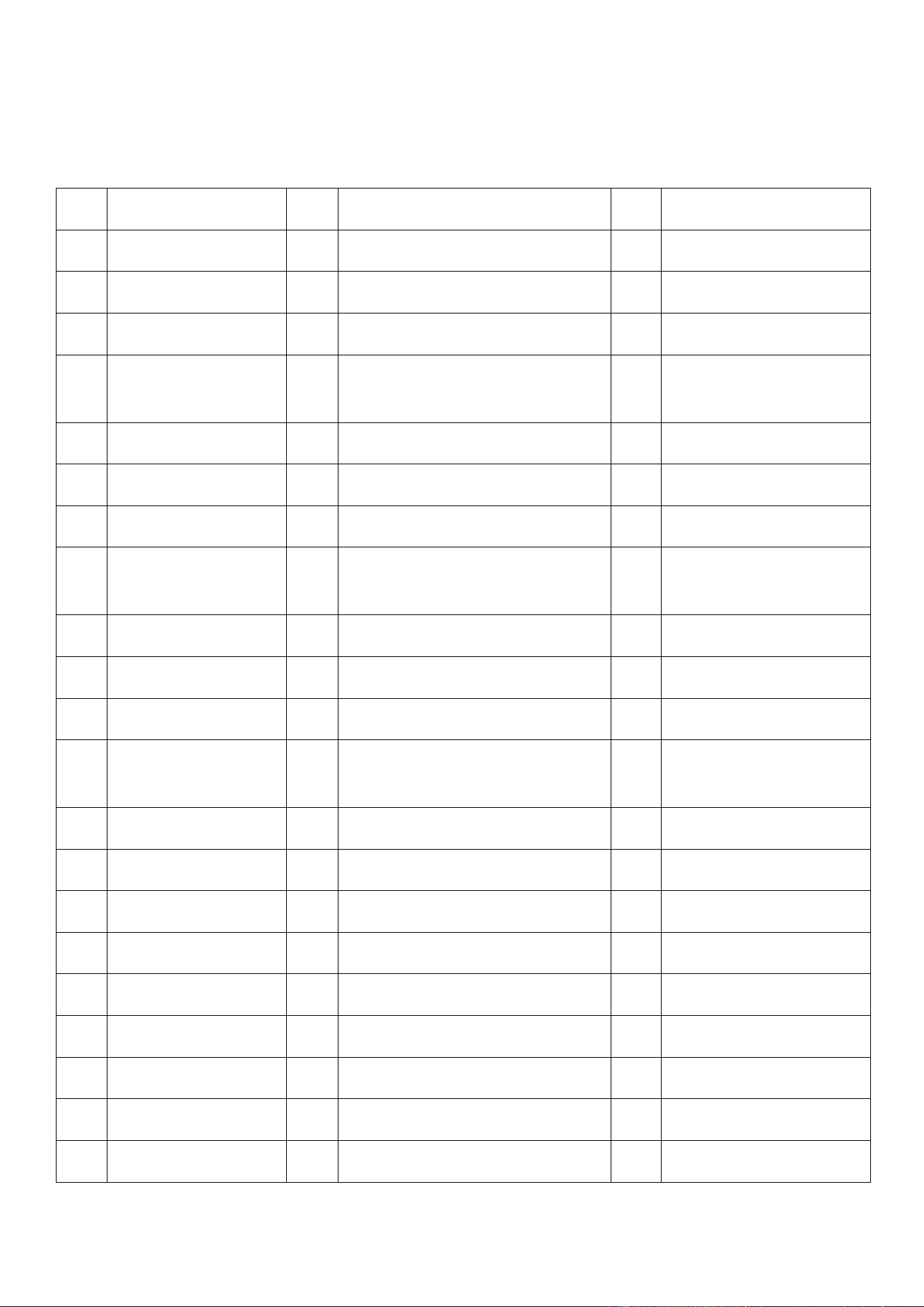
30
No.
Name
No.
Name
No.
Name
1
M8-40 screw
31
6308 bearing
61
Stroke switch sleeve
2
Phi 8 elastic flat pad
32
Bearing seat
62
Stroke switch rotary shaft
3
M8 nut
33
Sealing ring
63
M6 screw
4
Center pole
34
Upper shaft
64
Lower spindle upper belt
pulley
5
Face barrels
35
Dust cover
65
Casing welded parts
6
Lower axis
36
M16-40 screw
66
Lower spindle
7
Bearing cover
37
M10-30 screw
67
6307 bearing
8
Sealing ring
38
Screw hook
68
M8-45 screws, nuts, washers,
flat pad diameter 8
9
Phi 10 elastic flat pad
39
Net cover lever
69
Bearing sleeve
10
M10-30 screw
40
Net cover
70
6307 sleeve
11
V-type narrow belt 3V600
41
M8 nut
71
10-40 square key
12
Sealing ring
42
Base repair door
72
Under the main shaft of the
belt pulley
13
Phi 10 elastic flat pad
43
M6 screw
73
M10-30 screw
14
M10-30 screw
44
M8-20 screw diameter 8 elastic flat pad
74
Gaskets
15
Drum belt pulley
45
M8-20 screw diameter 8 flat pad
75
M10830 screw
16
M10-50 flat key
46
M8 nut
76
V type narrow belt SPZ1662LW
17
Adjusting washer
47
M8-20 nut
77
Bearing sleeve seat
18
6308 bearing
48
Baffle
78
6-30 square key
19
Lower bearing seat
49
M5 cross screw
79
M10-30 screw
20
6308 bearing
50
Stroke switch seat
80
Base motor pulley
21
M5-10 cross screw
51
Stroke switch
81
10-40 square key

31
22
M10-25 with 10 screws,
flat pad elastic pad
52
Electrical support
82
Body repair door
23
M5 screw
53
Electrical enclosure
83
Base motor seat screw
24
Bearing cover
54
Electrical components
84
Motor bottom seat
25
6308 bearing
55
Control panel
85
M6-15 screw
26
M10-30 screw
56
Wire
86
Adjustment screw with 10 flat
pads
27
M10 playing the flat pad
57
Fiber glass
87
M10-15 screw
28
Upper shaft pulley
58
M5-5 cross head screw
88
Motor belt pulley
29
V type narrow belt
59
M6-15 cross head screw
89
Motor positioning shaft
30
10-66 square key
60
M6 stud
90
Motor positioning sheath
CLEANING INSTRUCTIONS:
1. Take off any remaining debris.
- Use a nylon brush or a cloth towel to gently remove any piece of dough.
2. Wipe down to clean.
- Use an approved detergent and water solution OR a vinegar and water solution to wipe down the bowl and hook.
3. Rinse down.
- Use clean water and cloth to wipe down.
4. Sanitize.
- Use approved sanitizers. Follow manufacturer’s instructions exactly, be sure to wipe entire machine.
5. Air dry.
DO NOT
- Use any types of bleach (hypo sodium chloride).
- Fill with water/ hose down.
- Use steel wool/scrubber pads or anything abrasive.
SERVICE AND WARRANTY:
Please contact Eurodib: [email protected] or 1-888-956-6866