
Technical Support and E-Warranty Certificate
www.vevor.com/support
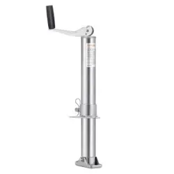
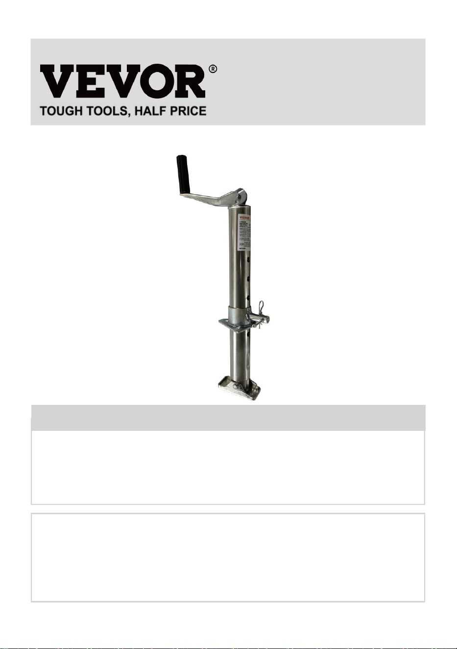
A-FRAME JACK
MODEL: TJAA-2000B
We continue to be committed to provide you tools with competitive price.
"Save Half", "Half Price" or any other similar expressions used by us only represents an
estimate of savings you might benefit from buying certain tools with us compared to the major
top brands and does not necessarily mean to cover all categories of tools offered by us. You
are kindly reminded to verify carefully when you are placing an order with us if you are
actually saving half in comparison with the top major brands.

- 1 -
MODEL:TJAA-2000B
Have product questions? Need technical support? Please feel free to
contact us:
Technical Support and E-Warranty Certificate
www.vevor.com/support
NEED HELP? CONTACT US!
This is the original instruction, please read all manual instructions
carefully before operating. VEVOR reserves a clear interpretation of our
user manual. The appearance of the product shall be subject to the
product you received. Please forgive us that we won't inform you again if
there are any technology or software updates on our product.
A-FRAME JACK

- 2 -
SAFETY INSTRUCTIONS
1. The “WARNING” symbol above is a sign that a service or maintenance
procedure involves a safety risk and may cause death or serious injury
if not performed safely and within the parameters set forth in this
manual.
2. Always wear eye protection when performing service or maintenance
to the vehicle. Other safety equipment to consider would be hearing
protection, gloves and possibly a full face shield, depending on the
nature of the service.
3. Never allow anyone unfamiliar with this product to install, operate or
service this product.
4. Never lift or level the trailer without a properly installed foot pad.
5. Never crank the jack or couple the trailer without preventing the trailer
from rolling.
6. Never exert excessive side forces on the trailer jack.
7. Never allow anyone, including the operator, to put any body parts
under the trailer jack or the supported load during jack operation.
8. Never exceed the load capacity !
9. Never use a trailer jack to lift the trailer for service or tire change.
10. Never move the trailer before the trailer jack is fully retracted.
11. Keep children and bystanders away from the work area while
operating the tool. Do not allow children to handle the jack.
12. It is for use on flat, level, hard surfaces capable of supporting load.
13. Do not use blocks for additional ground clearance.
14. When using the drop foot or drop leg, make certain the supplied pin is
fully inserted through both sides of the inner tube and the drop tube
before using the jack.
15. If the trailer jack has a drop leg, never attempt to adjust the drop leg
when there is any load on the jack.
Note:
1. The jack is only designed for vertical movement of the trailer.
- 3 -
2. Rapid and continuous lifting is not recommended to avoid gear heating
and reduce service life.
MODEL AND PARAMETERS
Model
TJAA-2000B
Capacity
2000 lbs
Mounting Bracket Type
A-Frame Mounting Bracket
Crank Type
Top-Wind
Range
5.8-28inch
Screw Travel
14.2inch
Foot Size
4.53x2.3" (Rectangle)
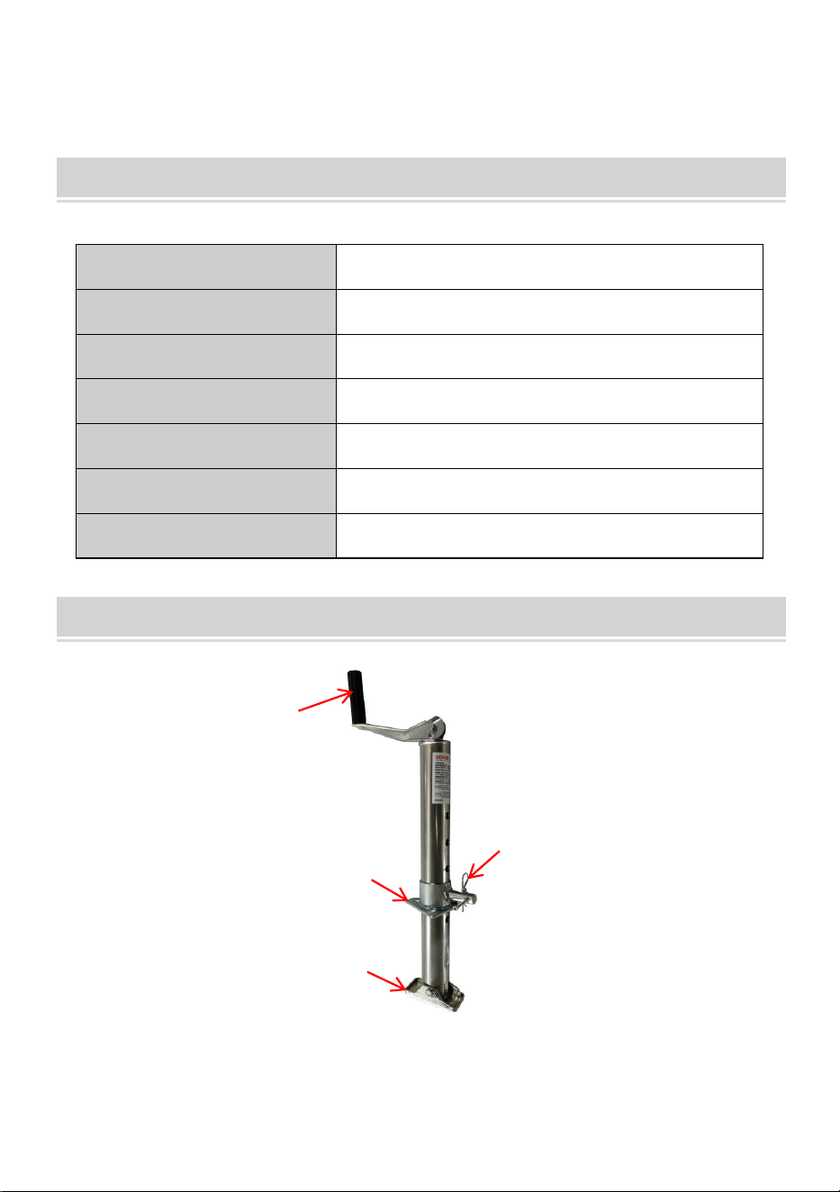
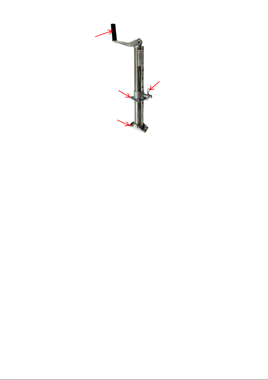
STRUCTURE DIAGRAM
1.Handle 2.Connecting Plate 3.Safety Pin 4.Foot Plate
1
2
3
4

- 4 -
COMPONENTS
No.
Picture
Name
Qty
1
Jack
1
2
User Manual
1
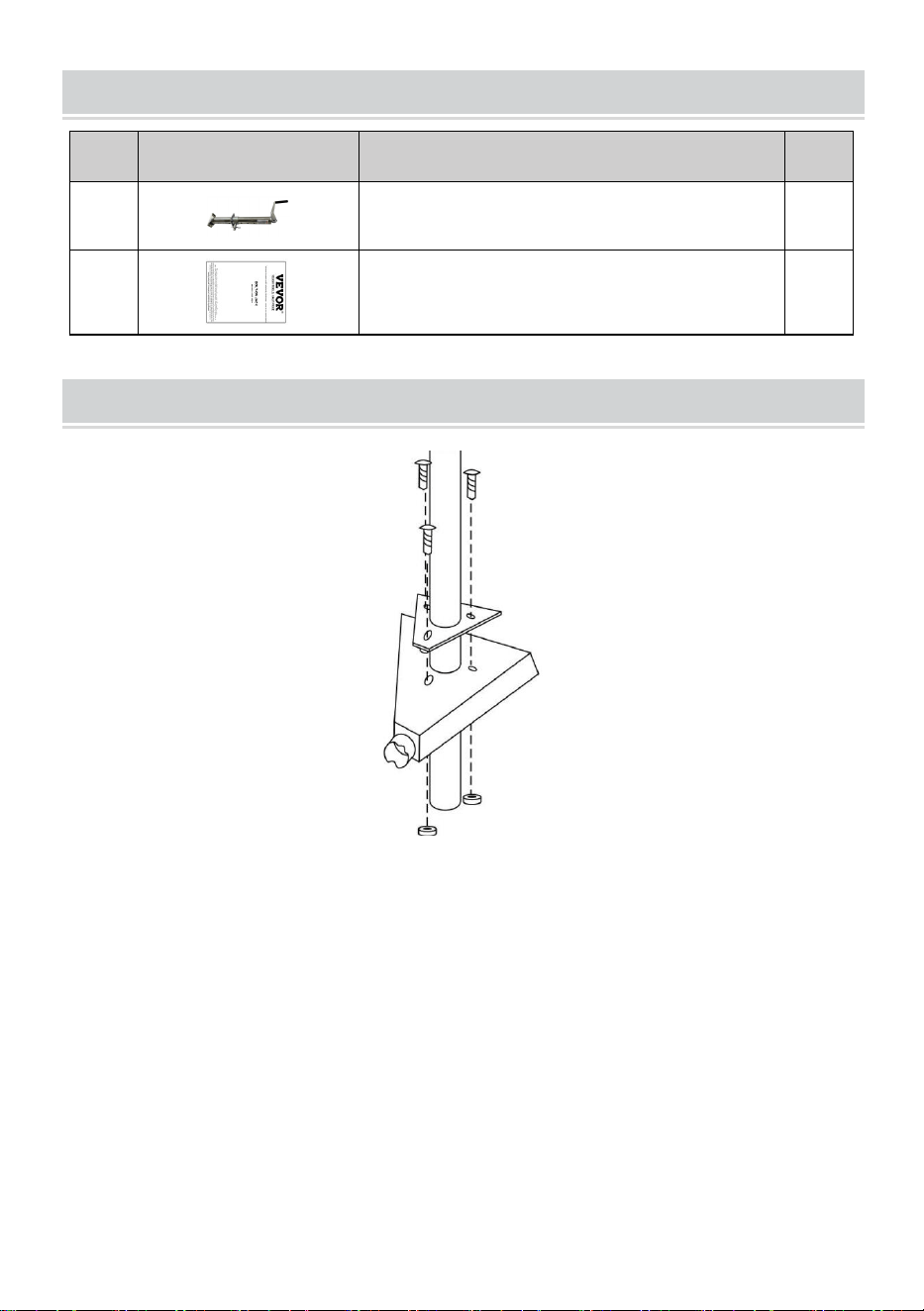
ASSEMBLY
1. When mounting trailer jack, it is best to hook up to the tow vehicle to
make sure the trailer is secure.
2. Mount jack based on drawing shown above.
3. Slide A-frame jack through hole on top of A-frame coupler.
4. Line up the three slotted holes on jack mounting plate to the three
holes in the coupler.
5. With three bolts and nuts (sold separately) secure jack tightly to the top
of the a-frame coupler. (Regularly check to ensure bolts/nuts are
tightened securely.)
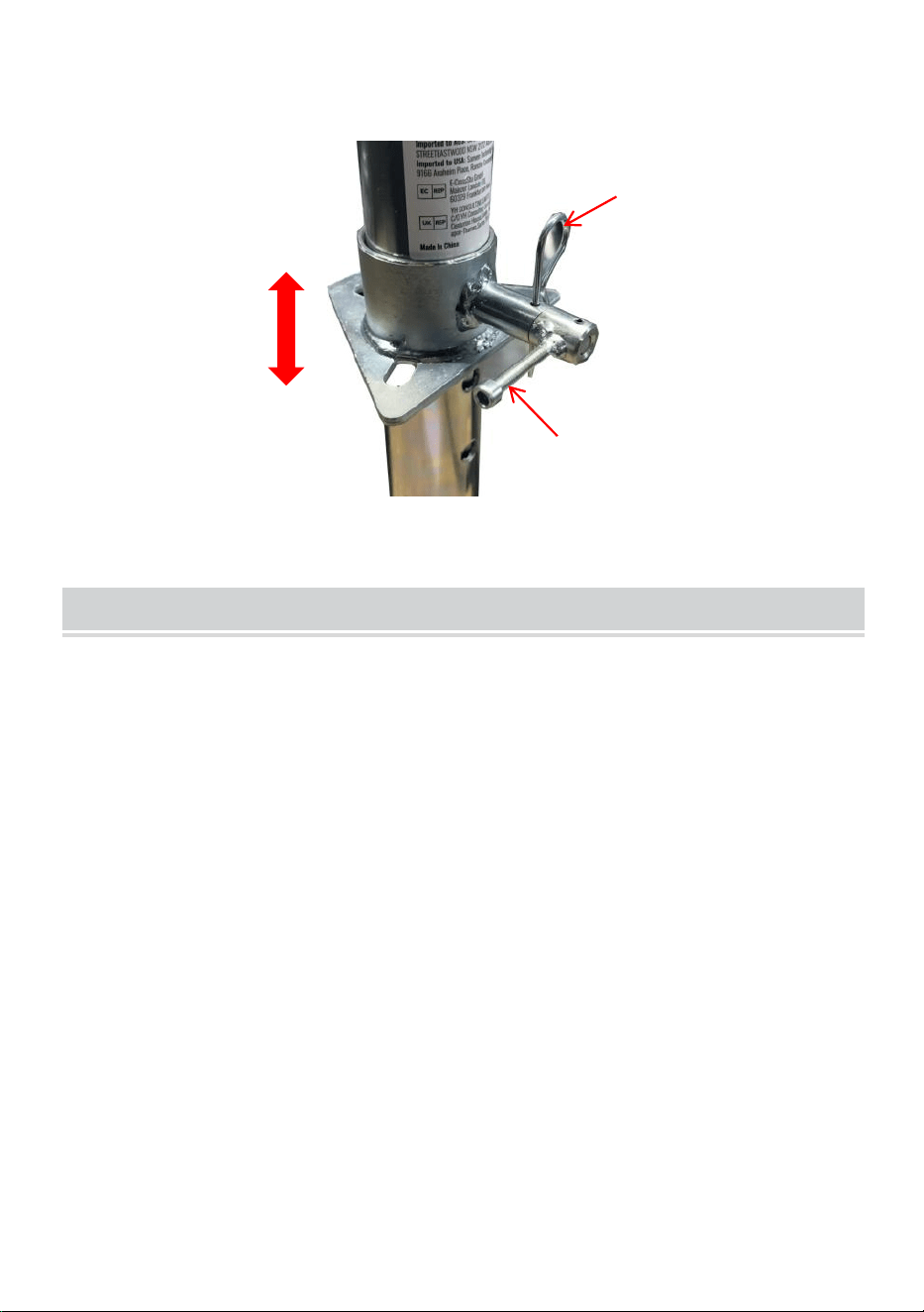
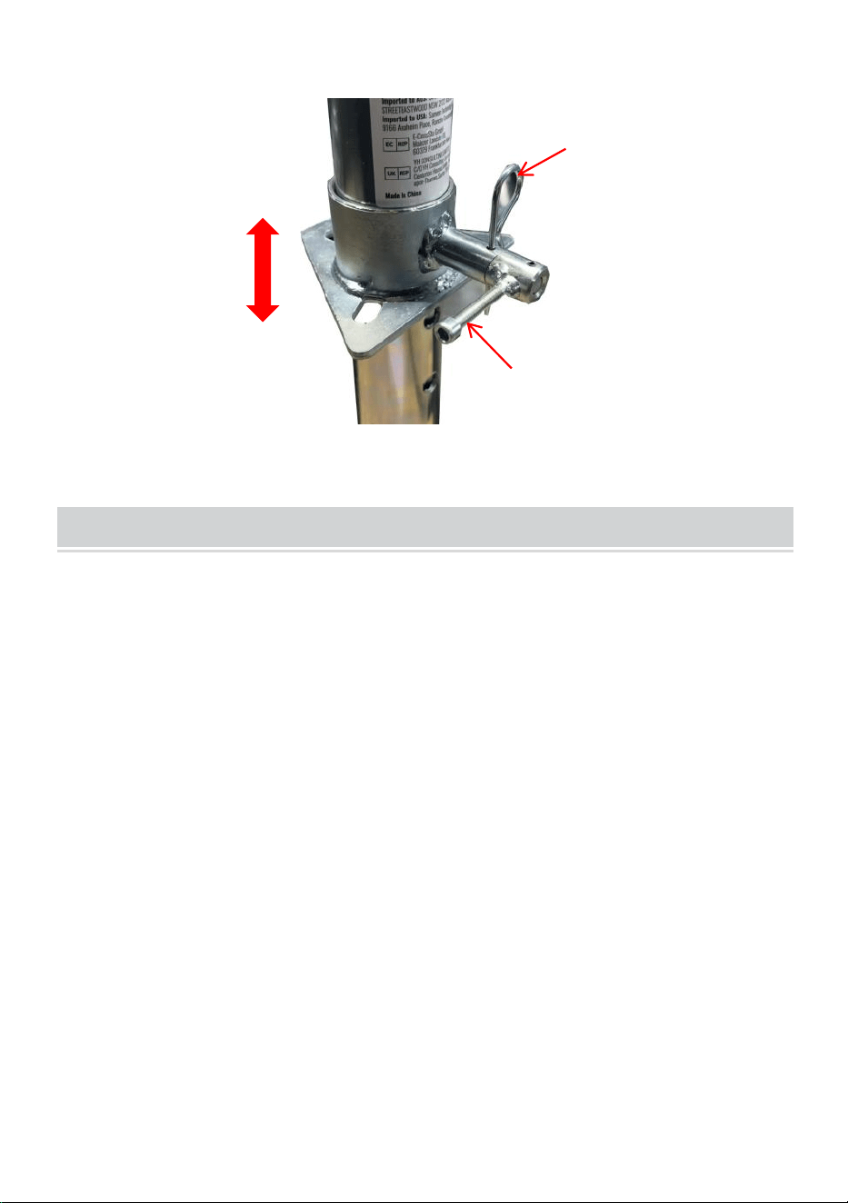
6. Select the appropriate hole position according to the body height.
- 5 -
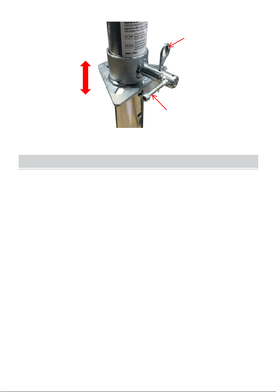
WARNING: Make sure you plug in the safety pin !
OPERATION
1. Turn handle clockwise to raise.
2. Turn handle counterclockwise to lower.
Safety Pin
Rotate to release
the clamp shaft.
- 6 -
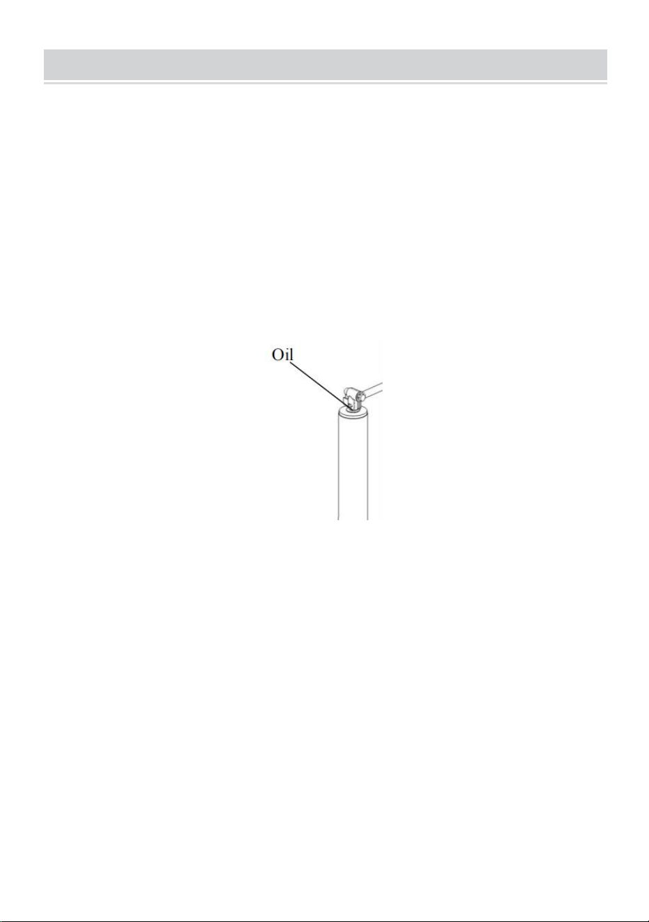
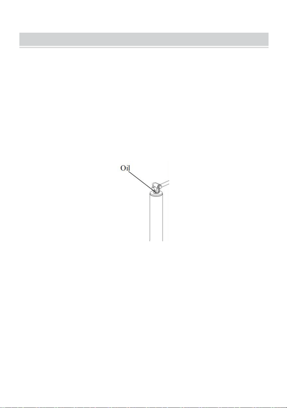
MAINTENANCE
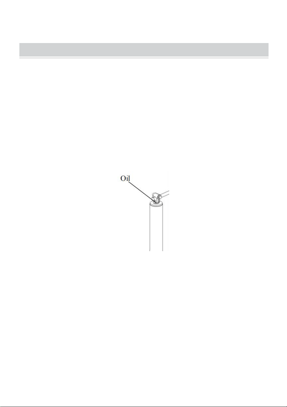
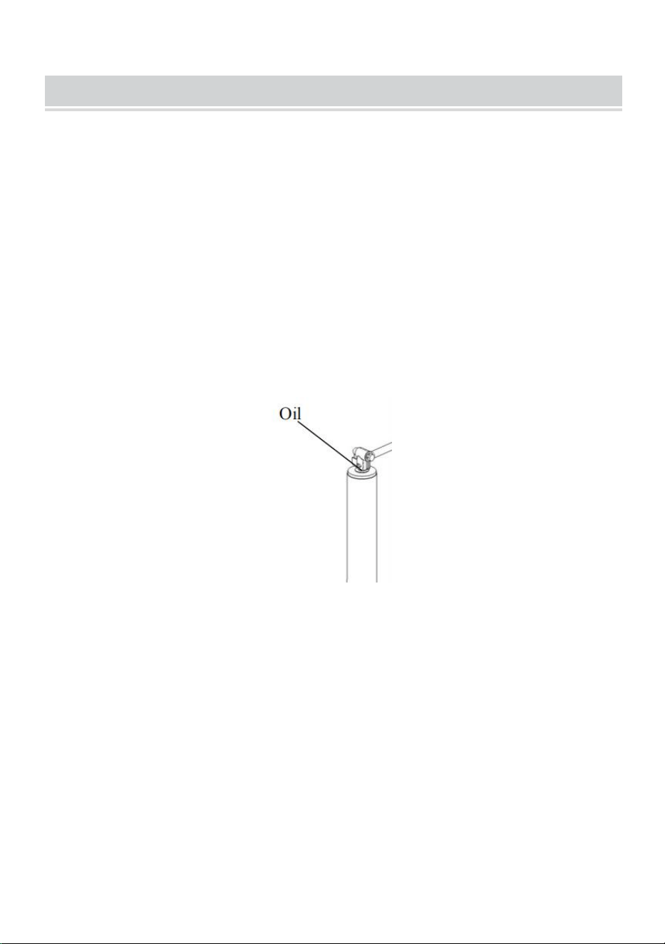
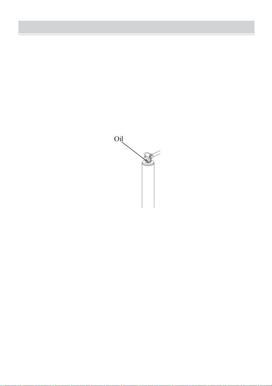
1. Occasional cleaning with mild soap and water, along with light oil
lubrication of pivot points, will prolong peak performance and
appearance.
2. Periodically check whether the screws are loose.
3. Before each use, inspect jack tubes and replace them if bent or
damaged.
4. The following procedures should be performed at least annually:
Apply a lightweight oil to the screw stem. If this product is used in a
marine environment, flush the jack assembly and bushings with fresh
water, and apply fresh lubricant.


- 8 -
Assistance technique et certificat de garantie électronique
www.vevor.com/support
CRIC À CADRE EN A
MODÈLE : TJAA-2000B
We continue to be committed to provide you tools with competitive price.
"Save Half", "Half Price" or any other similar expressions used by us only represents an
estimate of savings you might benefit from buying certain tools with us compared to the major
top brands and does not necessarily mean to cover all categories of tools offered by us. You
are kindly reminded to verify carefully when you are placing an order with us if you are
actually saving half in comparison with the top major brands.

- 1 -
MODÈLE : TJAA-2000B
Have product questions? Need technical support? Please feel free to
contact us:
Technical Support and E-Warranty Certificate
www.vevor.com/support
NEED HELP? CONTACT US!
This is the original instruction, please read all manual instructions
carefully before operating. VEVOR reserves a clear interpretation of our
user manual. The appearance of the product shall be subject to the
product you received. Please forgive us that we won't inform you again if
there are any technology or software updates on our product.
A-FRAME JACK

- 2 -
SAFETY INSTRUCTIONS
16. Le symbole « AVERTISSEMENT » ci-dessus est un signe qu'une
procédure d'entretien ou de maintenance comporte un risque de
sécurité et peut entraîner la mort ou des blessures graves si elle n'est
pas effectuée en toute sécurité et dans les paramètres définis dans ce
manuel.
17. Portez toujours une protection pour les yeux lorsque vous effectuez
des travaux d'entretien ou de maintenance sur le véhicule. D'autres
équipements de sécurité à prendre en compte sont une protection
auditive, des gants et éventuellement un écran facial complet, selon la
nature de l'entretien.
18. Ne laissez jamais une personne non familière avec ce produit installer,
utiliser ou entretenir ce produit.
19. Ne soulevez ou ne nivelez jamais la remorque sans un pied
correctement installé. tampon.
20. Ne jamais actionner le cric ni atteler la remorque sans empêcher la
remorque de rouler.
21. N’exercez jamais de forces latérales excessives sur le cric de la
remorque.
22. Ne laissez jamais personne, y compris l'opérateur, placer une partie
du corps sous le cric de la remorque ou sous la charge supportée
pendant le fonctionnement du cric.
23. Ne jamais dépasser la capacité de charge !
24. N’utilisez jamais un cric de remorque pour soulever la remorque en
vue d’un entretien ou d’un changement de pneu.
25. Ne déplacez jamais la remorque avant que le cric de la remorque ne
soit complètement rétracté.
26. Tenez les enfants et les personnes présentes à l'écart de la zone de
travail pendant l'utilisation de l'outil. Ne laissez pas les enfants
manipuler le cric.

- 3 -
27. Il est destiné à être utilisé sur des surfaces planes, horizontales et
dures capables de supporter une charge.
28. N'utilisez pas de blocs pour augmenter la garde au sol.
29. Lorsque vous utilisez le pied ou la jambe de force, assurez-vous que
la goupille fournie est complètement insérée dans les deux côtés du
tube intérieur et du tube de force avant d'utiliser le cric.
30. Si le cric de remorque est équipé d'un pied de support, n'essayez
jamais de régler ce dernier lorsqu'une charge est placée sur le cric.
Note:
3. Le cric est conçu uniquement pour le mouvement vertical de la
remorque.
4. Un levage rapide et continu n'est pas recommandé pour éviter
l'échauffement des engrenages et réduire leur durée de vie .
MODEL AND PARAMETERS
Modèle
TJAA-2000B
Capacité
2000 livres
Type de support de
Support de montage en A
Type de manivelle
Haut -vent
Gamme
5,8 à 28 pouces
Vis de déplacement
14,2 pouces
Taille du pied
4,53 x 2,3" (rectangulaire)
STRUCTURE DIAGRAM

- 4 -
1. Poignée 2. Plaque de connexion 3. Goupille de sécurité 4. Plaque
de pied
1
2
3
4

- 5 -
COMPONENTS
Non
Image
Nom
Qu
1
Jack
1
2
Manuel d'utilisation
1
ASSEMBLY
7. Lors du montage du cric de remorque, il est préférable de l'accrocher
au véhicule tracteur pour s'assurer que la remorque est sécurisée.
8. Montez le cric selon le dessin ci-dessus .
9. Faites glisser le cric du cadre en A à travers le trou situé sur le dessus
du coupleur du cadre en A.
10. Alignez les trois trous fendus de la plaque de montage du cric avec les
trois trous du coupleur.
11. Avec trois Des boulons et des écrous (vendus séparément) fixent
fermement le cric au sommet du coupleur à cadre en A. (Vérifiez
régulièrement que les boulons/écrous sont bien serrés.)
12. Sélectionnez la position du trou appropriée en fonction de la hauteur

- 6 -
du corps.
ATTENTION : Veillez à brancher la goupille de sécurité !
OPERATION
3. Tournez la poignée dans le sens des aiguilles d'une montre pour
soulever.
4. Tournez la poignée dans le sens inverse des aiguilles d'une montre
pour l'abaisser.
Safety Pin
Rotate to release
the clamp shaft.
- 7 -
MAINTENANCE
5. Un nettoyage occasionnel avec du savon doux et de l'eau , ainsi
qu'une lubrification légère à l'huile des points de pivot , prolongeront
les performances et l'apparence optimales.
6. Vérifiez régulièrement si les vis sont desserrées.
7. Avant chaque utilisation, inspectez les tubes du cric et remplacez- les
s'ils sont pliés ou endommagés.
8. Les procédures suivantes doivent être effectuées au moins une
fois par an : Appliquez une huile légère sur la tige de la vis. Si ce
produit est utilisé dans un environnement marin, rincez l'ensemble du
cric et les bagues à l'eau douce et appliquez du lubrifiant neuf.


- 9 -
Technischer Support und E-Garantie-Zertifikat
www.vevor.com/support
A-RAHMENWAGENHEBER
MODELL: TJAA-2000B
We continue to be committed to provide you tools with competitive price.
"Save Half", "Half Price" or any other similar expressions used by us only represents an
estimate of savings you might benefit from buying certain tools with us compared to the major
top brands and does not necessarily mean to cover all categories of tools offered by us. You
are kindly reminded to verify carefully when you are placing an order with us if you are
actually saving half in comparison with the top major brands.

- 1 -
MODELL: TJAA-2000B
Have product questions? Need technical support? Please feel free to
contact us:
Technical Support and E-Warranty Certificate
www.vevor.com/support
NEED HELP? CONTACT US!
This is the original instruction, please read all manual instructions
carefully before operating. VEVOR reserves a clear interpretation of our
user manual. The appearance of the product shall be subject to the
product you received. Please forgive us that we won't inform you again if
there are any technology or software updates on our product.
A-FRAME JACK

- 2 -
SAFETY INSTRUCTIONS
31. Das oben stehende Symbol „WARNUNG“ weist darauf hin, dass ein
Service- oder Wartungsvorgang ein Sicherheitsrisiko birgt und zum
Tod oder zu schweren Verletzungen führen kann, wenn er nicht sicher
und innerhalb der in diesem Handbuch festgelegten Parameter
durchgeführt wird.
32. Tragen Sie bei Wartungs- oder Instandhaltungsarbeiten am Fahrzeug
immer einen Augenschutz. Weitere zu berücksichtigende
Sicherheitsausrüstung sind Gehörschutz, Handschuhe und je nach Art
der Wartung möglicherweise ein Vollgesichtsschutz.
33. Erlauben Sie niemals jemandem, der mit diesem Produkt nicht vertraut
ist, die Installation, Bedienung oder Wartung dieses Produkts.
34. Den Anhänger niemals ohne ordnungsgemäß installierten Fuß
anheben oder nivellieren. Unterlage.
35. Betätigen Sie niemals die Stütze oder kuppeln Sie den Anhänger an,
ohne ihn am Wegrollen zu hindern.
36. Üben Sie niemals übermäßige seitliche Kräfte auf die Stütze des
Anhängers aus.
37. Erlauben Sie niemals jemandem, einschließlich dem Bediener,
während des Wagenheberbetriebs Körperteile unter den Wagenheber
oder die getragene Last zu bringen.
38. Die zulässige Tragkraft darf auf keinen Fall überschritten werden!
39. Verwenden Sie niemals einen Anhängerwagenheber, um den
Anhänger für Wartungsarbeiten oder zum Reifenwechsel anzuheben.
40. Bewegen Sie den Anhänger niemals, bevor die Stütze vollständig
eingefahren ist.
41. Halten Sie Kinder und andere Personen während der Arbeit mit dem
Werkzeug vom Arbeitsbereich fern. Erlauben Sie Kindern nicht, den
Wagenheber zu bedienen.
42. Es ist für den Einsatz auf flachen, ebenen, harten und tragfähigen
Oberflächen vorgesehen .

- 3 -
43. Verwenden Sie keine Blöcke für zusätzliche Bodenfreiheit.
44. Wenn Sie den Fallfuß oder das Fallbein verwenden, achten Sie darauf,
dass der mitgelieferte Stift vollständig durch beide Seiten des
Innenrohrs und des Fallrohrs eingeführt ist, bevor Sie den
Wagenheber verwenden.
45. Wenn der Wagenheber über ein Ausfallende verfügt, versuchen Sie
niemals, das Ausfallende einzustellen, wenn auf dem Wagenheber
eine Last lastet.
Notiz:
5. Der Wagenheber ist nur zum vertikalen Bewegen des Anhängers
vorgesehen.
6. Schnelles und kontinuierliches Anheben wird nicht empfohlen, da sich
das Getriebe sonst überhitzen und die Lebensdauer verkürzt .
MODEL AND PARAMETERS
Modell
TJAA-2000B
Kapazität
2000 Pfund
Typ der
A-Rahmen-Montagehalterung
Kurbeltyp
Top -Wind
Reichweite
5,8-28 Zoll
Schraube Reise
14,2 Zoll
Fußgröße
4,53 x 2,3 Zoll (Rechteck)
STRUCTURE DIAGRAM

- 4 -
1.Griff 2.Verbindungsplatte 3.Sicherheitsstift 4.Fußplatte
1
2
3
4

- 5 -
COMPONENTS
NEI
Bild
Name
Me
1
Jack
1
2
Bedienungsanleitung
1
ASSEMBLY
13. Beim Anbringen einer Anhängerstütze ist es am besten, diese an das
Zugfahrzeug anzukoppeln, um die Sicherheit des Anhängers zu
gewährleisten.
14. Montieren Sie die Buchse gemäß der oben gezeigten Zeichnung .
15. Schieben Sie den A-Rahmen-Wagenheber durch das Loch oben auf
der A-Rahmen-Kupplung.
16. Richten Sie die drei Langlöcher auf der Wagenhebermontageplatte an
den drei Löchern in der Kupplung aus.
17. Mit drei Schrauben und Muttern (separat erhältlich) befestigen den
Wagenheber fest an der Oberseite der A-Rahmenkupplung.
(Überprüfen Sie regelmäßig, ob die Schrauben/Muttern fest
- 6 -
angezogen sind.)
18. Wählen Sie je nach Körpergröße die passende Lochposition aus.
ACHTUNG: Unbedingt den Sicherungsstift einstecken!
OPERATION
5. Zum Anheben den Griff im Uhrzeigersinn drehen.
6. Zum Absenken den Griff gegen den Uhrzeigersinn drehen.
Safety Pin
Rotate to release
the clamp shaft.
- 7 -
MAINTENANCE
9. Gelegentliches Reinigen mit milder Seife und Wasser sowie eine
leichte Ölschmierung der Drehpunkte sorgen dafür , dass die Leistung
und das Aussehen länger erhalten bleiben.
10. Überprüfen Sie regelmäßig, ob die Schrauben locker sind.
11. Überprüfen Sie vor jedem Gebrauch die Wagenheberrohre und
ersetzen Sie sie , wenn sie verbogen oder beschädigt sind.
12. Die folgenden Verfahren sollten mindestens jährlich durchgeführt
werden: Tragen Sie ein leichtes Öl auf den Gewindeschaft auf. Wenn
dieses Produkt in einer Meeresumgebung verwendet wird, spülen Sie
die Wagenheberbaugruppe und die Buchsen mit Süßwasser und
tragen Sie frisches Schmiermittel auf.


- 9 -
Supporto tecnico e certificato di garanzia elettronica
www.vevor.com/support
CRIC A TELAIO A
MODELLO: TJAA-2000B
We continue to be committed to provide you tools with competitive price.
"Save Half", "Half Price" or any other similar expressions used by us only represents an
estimate of savings you might benefit from buying certain tools with us compared to the major
top brands and does not necessarily mean to cover all categories of tools offered by us. You
are kindly reminded to verify carefully when you are placing an order with us if you are
actually saving half in comparison with the top major brands.

- 1 -
MODELLO: TJAA-2000B
Have product questions? Need technical support? Please feel free to
contact us:
Technical Support and E-Warranty Certificate
www.vevor.com/support
NEED HELP? CONTACT US!
This is the original instruction, please read all manual instructions
carefully before operating. VEVOR reserves a clear interpretation of our
user manual. The appearance of the product shall be subject to the
product you received. Please forgive us that we won't inform you again if
there are any technology or software updates on our product.
A-FRAME JACK

- 2 -
SAFETY INSTRUCTIONS
46. Il simbolo "ATTENZIONE" sopra riportato indica che una procedura di
assistenza o manutenzione comporta un rischio per la sicurezza e può
causare morte o lesioni gravi se non eseguita in modo sicuro e
secondo i parametri stabiliti nel presente manuale.
47. Indossare sempre una protezione per gli occhi quando si esegue un
servizio o una manutenzione sul veicolo. Altri dispositivi di sicurezza
da considerare sono la protezione dell'udito, i guanti e, possibilmente,
una visiera completa, a seconda della natura del servizio.
48. Non consentire mai a chiunque non abbia familiarità con questo
prodotto di installarlo, utilizzarlo o eseguirne la manutenzione.
49. Non sollevare o livellare mai il rimorchio senza un piede correttamente
installato tampone.
50. Non azionare mai il cric o agganciare il rimorchio senza impedirne lo
spostamento.
51. Non esercitare mai forze laterali eccessive sul cric del rimorchio.
52. Non consentire mai a nessuno, compreso l'operatore, di posizionare
parti del corpo sotto il cric del rimorchio o sotto il carico supportato
durante il funzionamento del cric.
53. Non superare mai la capacità di carico!
54. Non utilizzare mai un cric per sollevare il rimorchio a scopo di
manutenzione o sostituzione degli pneumatici.
55. Non spostare mai il rimorchio prima che il cric sia completamente
retratto.
56. Tenere bambini e astanti lontani dall'area di lavoro mentre si utilizza
l'utensile. Non consentire ai bambini di maneggiare il martinetto.
57. È destinato all'uso su superfici piane, livellate e dure in grado di
sostenere carichi.
58. Non utilizzare blocchi per aumentare l'altezza libera dal suolo.
59. Quando si utilizza il piede di caduta o la gamba di caduta, assicurarsi
che il perno in dotazione sia completamente inserito attraverso

- 3 -
entrambi i lati del tubo interno e del tubo di caduta prima di utilizzare il
martinetto.
60. Se il cric del rimorchio è dotato di un piede di sollevamento, non
tentare mai di regolarlo quando il cric è carico.
Nota:
7. Il martinetto è progettato esclusivamente per lo spostamento verticale
del rimorchio.
8. Si sconsiglia il sollevamento rapido e continuo per evitare il
surriscaldamento degli ingranaggi e ridurne la durata utile .
MODEL AND PARAMETERS
Modello
Modello TJAA-2000B
Capacità
2000 libbre
Tipo di staffa di
Staffa di montaggio a telaio ad A
Tipo di manovella
Vento di punta
Allineare
5,8-28 pollici
Vite di viaggio
14,2 pollici
Misura del piede
4,53x2,3" (Rettangolo)
STRUCTURE DIAGRAM
- 4 -
1. Maniglia 2. Piastra di collegamento 3. Perno di sicurezza 4.
Piastra di base
1
2
3
4

- 5 -
COMPONENTS
NO.
Immagine
Nome
Qu
1
Jack
1
2
Manuale d'uso
1
ASSEMBLY
19. Quando si monta il cric per rimorchio, è meglio agganciarlo al veicolo
trainante per assicurarsi che il rimorchio sia fissato saldamente.
20. martinetto in base al disegno mostrato sopra .
21. Far scorrere il martinetto a telaio ad A attraverso il foro nella parte
superiore dell'accoppiatore a telaio ad A.
22. Allineare i tre fori asolati sulla piastra di montaggio del martinetto ai tre
fori nell'accoppiatore.
23. Con tre bulloni e dadi (venduti separatamente) fissano saldamente il
martinetto alla parte superiore dell'accoppiatore a telaio. (Controllare
regolarmente che bulloni/dadi siano serrati saldamente.)
24. Selezionare la posizione del foro appropriata in base all'altezza del
- 6 -
corpo.
ATTENZIONE: assicurarsi di aver inserito il perno di sicurezza!
OPERATION
7. Per sollevare, girare la maniglia in senso orario.
8. Per abbassare, girare la maniglia in senso antiorario.
Safety Pin
Rotate to release
the clamp shaft.

- 7 -
MAINTENANCE
13. Una pulizia occasionale con acqua e sapone neutro , insieme a una
leggera lubrificazione dei punti di snodo con olio , ne prolungherà le
massime prestazioni e l'aspetto.
14. Controllare periodicamente che le viti siano allentate.
15. Prima di ogni utilizzo, ispezionare i tubi del martinetto e sostituirli se
piegati o danneggiati.
16. Le seguenti procedure devono essere eseguite almeno una volta
all'anno: Applicare un olio leggero allo stelo della vite. Se questo
prodotto viene utilizzato in un ambiente marino, lavare il gruppo
martinetto e le boccole con acqua dolce e applicare lubrificante fresco.


- 9 -
Soporte técnico y certificado de garantía electrónica
www.vevor.com/support
GATO CON MARCO EN A
MODELO: TJAA-2000B
We continue to be committed to provide you tools with competitive price.
"Save Half", "Half Price" or any other similar expressions used by us only represents an
estimate of savings you might benefit from buying certain tools with us compared to the major
top brands and does not necessarily mean to cover all categories of tools offered by us. You
are kindly reminded to verify carefully when you are placing an order with us if you are
actually saving half in comparison with the top major brands.

- 1 -
MODELO: TJAA-2000B
Have product questions? Need technical support? Please feel free to
contact us:
Technical Support and E-Warranty Certificate
www.vevor.com/support
NEED HELP? CONTACT US!
This is the original instruction, please read all manual instructions
carefully before operating. VEVOR reserves a clear interpretation of our
user manual. The appearance of the product shall be subject to the
product you received. Please forgive us that we won't inform you again if
there are any technology or software updates on our product.
A-FRAME JACK

- 2 -
SAFETY INSTRUCTIONS
61. El símbolo de “ADVERTENCIA” que aparece arriba es una señal de
que un procedimiento de servicio o mantenimiento implica un riesgo
de seguridad y puede causar la muerte o lesiones graves si no se
realiza de manera segura y dentro de los parámetros establecidos en
este manual.
62. Utilice siempre protección para los ojos al realizar tareas de
mantenimiento o servicio en el vehículo. Otros equipos de seguridad
que se deben tener en cuenta son la protección auditiva, los guantes y,
posiblemente, una pantalla facial completa, según la naturaleza del
servicio.
63. Nunca permita que alguien que no esté familiarizado con este
producto instale, opere o realice mantenimiento del mismo.
64. Nunca levante ni nivele el remolque sin un soporte de pie instalado
correctamente. almohadilla.
65. Nunca gire el gato ni acople el remolque sin impedir que éste se
mueva.
66. Nunca ejerza fuerzas laterales excesivas sobre el gato del remolque.
67. Nunca permita que nadie, incluido el operador, coloque partes del
cuerpo debajo del gato del remolque o de la carga soportada durante
el funcionamiento del gato.
68. ¡Nunca exceda la capacidad de carga!
69. Nunca use un gato de remolque para levantar el remolque para
realizar tareas de mantenimiento o cambiar neumáticos.
70. Nunca mueva el remolque antes de que el gato del remolque esté
completamente retraído.
71. Mantenga a los niños y a las personas que se encuentren cerca del
área de trabajo mientras utiliza la herramienta. No permita que los
niños manipulen el gato.
72. Está diseñado para usarse sobre superficies planas, niveladas y duras
capaces de soportar carga.

- 3 -
73. No utilice bloques para obtener mayor distancia al suelo.
74. Al utilizar el pie o la pata abatible, asegúrese de que el pasador
suministrado esté completamente insertado a través de ambos lados
del tubo interior y del tubo abatible antes de usar el gato.
75. Si el gato del remolque tiene una pata abatible, nunca intente ajustarla
cuando haya alguna carga sobre el gato.
Nota:
9. El gato está diseñado únicamente para el movimiento vertical del
remolque.
10. No se recomienda una elevación rápida y continua para evitar el
calentamiento del engranaje y reducir la vida útil .
MODEL AND PARAMETERS
Modelo
TJAA-2000B
Capacidad
2000 libras
Tipo de soporte de
Soporte de montaje en forma de A
Tipo de manivela
Viento superior
Rango
5,8-28 pulgadas
Viaje de tornillo
14,2 pulgadas
Tamaño del pie
4,53 x 2,3" (rectángulo)
STRUCTURE DIAGRAM

- 4 -
1. Mango 2. Placa de conexión 3. Pasador de seguridad 4. Placa de
pie
1
2
3
4

- 5 -
COMPONENTS
No.
Imagen
Nombre
Can
1
Jacobo
1
2
Manual de usuario
1
ASSEMBLY
25. Al montar el gato del remolque, es mejor engancharlo al vehículo
remolcador para asegurarse de que el remolque esté seguro.
26. el gato según el dibujo que se muestra arriba .
27. Deslice el gato en forma de A a través del orificio en la parte superior
del acoplador en forma de A.
28. Alinee los tres orificios ranurados de la placa de montaje del gato con
los tres orificios del acoplador.
29. Con tres Los pernos y las tuercas (se venden por separado) aseguran
firmemente el gato a la parte superior del acoplador del bastidor en
forma de A. (Verifique periódicamente que los pernos y las tuercas
estén bien apretados).

- 6 -
30. Seleccione la posición del orificio adecuada según la altura del
cuerpo.
ADVERTENCIA: ¡Asegúrese de conectar el pasador de seguridad!
OPERATION
9. Gire la manija en el sentido de las agujas del reloj para levantarla.
10. Gire la manija en sentido antihorario para bajar.
Safety Pin
Rotate to release
the clamp shaft.

- 7 -
MAINTENANCE
17. La limpieza ocasional con agua y jabón suave , junto con una ligera
lubricación con aceite de los puntos de pivote , prolongará el máximo
rendimiento y la apariencia.
18. Compruebe periódicamente si los tornillos están flojos.
19. Antes de cada uso, inspeccione los tubos del gato y reemplácelos si
están doblados o dañados.
20. Los siguientes procedimientos deben realizarse al menos
anualmente: Aplique un aceite liviano al vástago del tornillo. Si este
producto se utiliza en un entorno marino, enjuague el conjunto del
gato y los bujes con agua dulce y aplique lubricante nuevo.


- 9 -
Wsparcie techniczne i certyfikat e-gwarancji
www.vevor.com/support
PODNOŚNIK TYPU A
MODEL: TJAA-2000B
We continue to be committed to provide you tools with competitive price.
"Save Half", "Half Price" or any other similar expressions used by us only represents an
estimate of savings you might benefit from buying certain tools with us compared to the major
top brands and does not necessarily mean to cover all categories of tools offered by us. You
are kindly reminded to verify carefully when you are placing an order with us if you are
actually saving half in comparison with the top major brands.

- 1 -
MODEL: TJAA-2000B
Have product questions? Need technical support? Please feel free to
contact us:
Technical Support and E-Warranty Certificate
www.vevor.com/support
NEED HELP? CONTACT US!
This is the original instruction, please read all manual instructions
carefully before operating. VEVOR reserves a clear interpretation of our
user manual. The appearance of the product shall be subject to the
product you received. Please forgive us that we won't inform you again if
there are any technology or software updates on our product.
A-FRAME JACK

- 2 -
SAFETY INSTRUCTIONS
76. Symbol „OSTRZEŻENIE” powyżej oznacza, że procedura serwisowa
lub konserwacyjna wiąże się z ryzykiem dla bezpieczeństwa i może
spowodować śmierć lub poważne obrażenia, jeśli nie zostanie
wykonana bezpiecznie i zgodnie z parametrami określonymi w
niniejszej instrukcji.
77. Zawsze zakładaj okulary ochronne podczas wykonywania serwisu lub
konserwacji pojazdu. Innym sprzętem bezpieczeństwa, który należy
wziąć pod uwagę, są ochronniki słuchu, rękawice i ewentualnie pełna
osłona twarzy, w zależności od charakteru serwisu.
78. Nigdy nie pozwalaj osobom niezaznajomionym z tym produktem na
instalację, obsługę lub serwisowanie tego produktu.
79. Nigdy nie podnoś ani nie poziomuj przyczepy bez prawidłowo
zamontowanej stopy. podkładka.
80. Nigdy nie należy uruchamiać podnośnika ani podłączać przyczepy bez
zabezpieczenia jej przed stoczeniem się.
81. Nigdy nie wywieraj nadmiernych sił bocznych na podnośnik przyczepy.
82. Nigdy nie pozwalaj nikomu, łącznie z operatorem, na umieszczanie
jakichkolwiek części ciała pod podnośnikiem przyczepy lub
podtrzymywanym ładunkiem podczas obsługi podnośnika.
83. Nigdy nie przekraczaj dopuszczalnego udźwigu!
84. Nigdy nie używaj podnośnika przyczepy do podnoszenia przyczepy w
celu wykonania prac serwisowych lub wymiany opon.
85. Nigdy nie należy poruszać przyczepą, dopóki podnośnik przyczepy nie
zostanie całkowicie wsunięty.
86. Trzymaj dzieci i osoby postronne z dala od miejsca pracy podczas
obsługi narzędzia. Nie pozwalaj dzieciom obsługiwać podnośnika.
87. Przeznaczony jest do stosowania na płaskich, równych, twardych
powierzchniach , które mogą wytrzymać obciążenie.
88. Nie należy stosować klocków w celu uzyskania dodatkowego
prześwitu.

- 3 -
89. W przypadku korzystania z opuszczanej stopy lub opuszczanej nogi,
przed użyciem podnośnika należy upewnić się, że dołączony sworzeń
jest całkowicie wsunięty przez obie strony rury wewnętrznej i rury
opuszczanej.
90. Jeśli podnośnik przyczepy jest wyposażony w opuszczaną nogę, nigdy
nie próbuj jej regulować, gdy na podnośniku znajduje się jakikolwiek
ładunek.
Notatka:
11. Podnośnik jest przeznaczony wyłącznie do pionowego ruchu
przyczepy.
12. Nie zaleca się szybkiego i ciągłego podnoszenia, aby uniknąć
nagrzewania się przekładni i skrócić jej żywotność .
MODEL AND PARAMETERS
Model
TJAA-2000B
Pojemność
2000 funtów
Typ uchwytu
Uchwyt montażowy ramy A
Typ korby
Góra -Wiatr
Zakres
5,8-28 cali
Śruba Podróż
14,2 cala
Rozmiar stopy
4,53x2,3" (prostokąt)
STRUCTURE DIAGRAM

- 4 -
1. Uchwyt 2. Płytka łącząca 3. Kołek zabezpieczający 4. Płytka
podnóżka
1
2
3
4

- 5 -
COMPONENTS
NIE
Zdjęcie
Nazwa
Iloś
1
Podnośnik
1
2
Instrukcja obsługi
1
ASSEMBLY
31. Podczas montażu podnośnika przyczepy najlepiej jest podłączyć ją do
pojazdu holującego, aby mieć pewność, że przyczepa jest
bezpieczna.
32. Zamontuj podnośnik w oparciu o rysunek powyżej .
33. Przesuń podnośnik ramy A przez otwór znajdujący się na górze
łącznika ramy A.
34. Dopasuj trzy otwory szczelinowe na płycie montażowej podnośnika do
trzech otworów w łączniku.
35. Z trzema Śruby i nakrętki (sprzedawane oddzielnie) mocują podnośnik
ściśle do górnej części łącznika ramy w kształcie litery A. (Regularnie
sprawdzaj, czy śruby/nakrętki są solidnie dokręcone.)

- 6 -
36. Wybierz odpowiednią pozycję otworu w zależności od wzrostu ciała.
OSTRZEŻENIE: Upewnij się, że włożyłeś agrafkę!
OPERATION
11. Aby podnieść, obróć uchwyt zgodnie z ruchem wskazówek zegara.
12. Aby opuścić, przekręć uchwyt przeciwnie do ruchu wskazówek
zegara.
Safety Pin
Rotate to release
the clamp shaft.
- 7 -
MAINTENANCE
21. Okazjonalne czyszczenie łagodnym mydłem i wodą , a także lekkie
smarowanie punktów obrotowych olejem , przedłuży optymalną
wydajność i wygląd.
22. Sprawdzaj okresowo, czy śruby nie są poluzowane.
23. Przed każdym użyciem należy sprawdzić rury podnośnika i wymienić
je , jeśli są wygięte lub uszkodzone.
24. Poniższe zabiegi należy wykonywać przynajmniej raz w roku:
Nałóż lekki olej na trzpień śruby. Jeśli ten produkt jest używany w
środowisku morskim, przepłucz zespół podnośnika i tuleje słodką
wodą i nałóż świeży smar.


- 9 -
Technische ondersteuning en e-garantiecertificaat
www.vevor.com/support
A-FRAME-KRUK
MODEL: TJAA-2000B
We continue to be committed to provide you tools with competitive price.
"Save Half", "Half Price" or any other similar expressions used by us only represents an
estimate of savings you might benefit from buying certain tools with us compared to the major
top brands and does not necessarily mean to cover all categories of tools offered by us. You
are kindly reminded to verify carefully when you are placing an order with us if you are
actually saving half in comparison with the top major brands.

- 1 -
MODEL: TJAA-2000B
Have product questions? Need technical support? Please feel free to
contact us:
Technical Support and E-Warranty Certificate
www.vevor.com/support
NEED HELP? CONTACT US!
This is the original instruction, please read all manual instructions
carefully before operating. VEVOR reserves a clear interpretation of our
user manual. The appearance of the product shall be subject to the
product you received. Please forgive us that we won't inform you again if
there are any technology or software updates on our product.
A-FRAME JACK

- 2 -
SAFETY INSTRUCTIONS
91. Het bovenstaande symbool “WAARSCHUWING” geeft aan dat een
service- of onderhoudsprocedure een veiligheidsrisico met zich
meebrengt en tot de dood of ernstig letsel kan leiden als deze niet
veilig en binnen de in deze handleiding uiteengezette parameters
wordt uitgevoerd.
92. Draag altijd oogbescherming bij het uitvoeren van service of
onderhoud aan het voertuig. Andere veiligheidsuitrusting om te
overwegen zou gehoorbescherming, handschoenen en mogelijk een
volledig gezichtsscherm zijn, afhankelijk van de aard van de service.
93. Laat nooit iemand die niet bekend is met dit product het product
installeren, bedienen of onderhouden.
94. Til of nivelleer de aanhanger nooit zonder een correct geïnstalleerde
voetsteun kussentje.
95. Draai nooit aan de krik en koppel de aanhanger nooit aan zonder dat u
de aanhanger tegen het rollen houdt.
96. Oefen nooit buitensporige zijwaartse krachten uit op de
aanhangwagenkrik.
97. Laat nooit iemand, inclusief de bestuurder, lichaamsdelen onder de
aanhangwagenkrik of de ondersteunde last steken terwijl de krik in
werking is.
98. Overschrijd nooit het draagvermogen!
99. Gebruik nooit een aanhangwagenkrik om de aanhangwagen op te
tillen voor onderhoud of het verwisselen van een band.
100. Verplaats de aanhanger nooit voordat de aanhangersteun volledig
is ingetrokken.
101. Houd kinderen en omstanders uit de buurt van het werkgebied
terwijl u het gereedschap bedient. Laat kinderen de krik niet hanteren.
102. Het is bedoeld voor gebruik op vlakke, vlakke, harde oppervlakken
die een last kunnen dragen.
103. Gebruik geen blokken voor extra bodemvrijheid.

- 3 -
104. Wanneer u de drop foot of drop leg gebruikt, zorg er dan voor dat
de meegeleverde pen volledig door beide zijden van de binnenbuis en
de drop tube is gestoken voordat u de krik gebruikt.
105. Als de aanhangwagenkrik een uitschuifbare poot heeft, mag u
nooit proberen de poot te verstellen als er een last op de krik rust.
Opmerking:
13. De krik is alleen ontworpen voor verticale verplaatsing van de
aanhangwagen.
14. Snel en continu heffen wordt afgeraden om oververhitting van de
tandwielen te voorkomen en de levensduur te verkorten .
MODEL AND PARAMETERS
Model
TJAA-2000B
C apaciteit
2000 pond
Montage B racket Type
A-frame montagebeugel
Krukastype
Boven -Wind
Bereik
5,8-28 inch
Schroef reizen
14,2 inch
Voetmaat
4,53x2,3" (rechthoek)
STRUCTURE DIAGRAM

- 4 -
1.Handvat 2.Verbindingsplaat 3.Veiligheidspen 4.Voetplaat
1
2
3
4
- 5 -
COMPONENTS
Nee
Afbeelding
Naam
Hoe
1
krik
1
2
Gebruiksaanwijzing
1
ASSEMBLY
37. Wanneer u een aanhangwagenkrik monteert, kunt u deze het beste
aan het trekkende voertuig koppelen om er zeker van te zijn dat de
aanhangwagen stevig staat.
38. Monteer de jack op basis van de tekening hierboven .
39. Schuif de A-frame-krik door het gat boven op de A-frame-koppeling.
40. Lijn de drie sleufgaten op de montageplaat van de krik uit met de drie
gaten in de koppeling.
41. Met drie Bouten en moeren (apart verkrijgbaar) bevestigen de krik
stevig aan de bovenkant van de A-framekoppeling. (Controleer
regelmatig of de bouten/moeren goed vastzitten.)
42. Selecteer de juiste positie voor het gat, afhankelijk van de

- 6 -
lichaamslengte.
WAARSCHUWING: Zorg ervoor dat u de veiligheidsspeld in het stopcontact
steekt!
OPERATION
13. Draai de hendel met de klok mee om hem omhoog te brengen.
14. Draai de hendel tegen de klok in om te laten zakken.
Safety Pin
Rotate to release
the clamp shaft.

- 7 -
MAINTENANCE
25. Door af en toe schoon te maken met milde zeep en water en de
draaipunten licht te smeren met olie , blijven de prestaties en het
uiterlijk optimaal.
26. Controleer regelmatig of de schroeven loszitten.
27. Controleer voor elk gebruik de krikbuizen en vervang ze als ze
verbogen of beschadigd zijn.
28. De volgende procedures dienen minimaal jaarlijks te worden
uitgevoerd: Breng een lichte olie aan op de schroefsteel. Als dit
product in een maritieme omgeving wordt gebruikt, spoel dan de
krikconstructie en bussen met zoet water en breng vers smeermiddel
aan.


- 9 -
Teknisk support och e-garanticertifikat
www.vevor.com/support
A-FRAME JACK
MODELL: TJAA-2000B
We continue to be committed to provide you tools with competitive price.
"Save Half", "Half Price" or any other similar expressions used by us only represents an
estimate of savings you might benefit from buying certain tools with us compared to the major
top brands and does not necessarily mean to cover all categories of tools offered by us. You
are kindly reminded to verify carefully when you are placing an order with us if you are
actually saving half in comparison with the top major brands.
- 1 -
MODELL: TJAA-2000B
Have product questions? Need technical support? Please feel free to
contact us:
Technical Support and E-Warranty Certificate
www.vevor.com/support
NEED HELP? CONTACT US!
This is the original instruction, please read all manual instructions
carefully before operating. VEVOR reserves a clear interpretation of our
user manual. The appearance of the product shall be subject to the
product you received. Please forgive us that we won't inform you again if
there are any technology or software updates on our product.
A-FRAME JACK

- 2 -
SAFETY INSTRUCTIONS
106. "VARNING"-symbolen ovan är ett tecken på att en service- eller
underhållsprocedur innebär en säkerhetsrisk och kan orsaka dödsfall
eller allvarlig skada om den inte utförs på ett säkert sätt och inom de
parametrar som anges i denna handbok.
107. Bär alltid ögonskydd när du utför service eller underhåll på
fordonet. Annan säkerhetsutrustning att överväga skulle vara
hörselskydd, handskar och eventuellt en hel ansiktsskärm, beroende
på tjänstens art.
108. Tillåt aldrig någon som inte är bekant med denna produkt att
installera, använda eller serva denna produkt.
109. Lyft eller nivellera aldrig vagnen utan en korrekt installerad fot
vaddera.
110.Veva aldrig domkraften eller koppla ihop släpet utan att hindra släpet
från att rulla.
111.Utöva aldrig för stora sidokrafter på släpvagnens domkraft.
112.Tillåt aldrig någon, inklusive operatören, att placera några kroppsdelar
under släpvagnsdomkraften eller den stödda lasten när domkraften
används.
113.Överskrid aldrig lastkapaciteten!
114.Använd aldrig en domkraft för att lyfta släpet för service eller däckbyte.
115.Flytta aldrig släpet innan domkraften är helt indragen.
116.Håll barn och åskådare borta från arbetsområdet när du använder
verktyget. Låt inte barn hantera domkraften.
117.Den är avsedd för användning på plana, jämna, hårda ytor som tål
last.
118.Använd inte block för ytterligare markfrigång.
119.När du använder fallfoten eller fallbenet, se till att den medföljande
stiftet är helt införd genom båda sidor av innerröret och fallröret innan
du använder domkraften.

- 3 -
120. Om släpvagnsdomkraften har ett fallben, försök aldrig justera
fallbenet när det är någon belastning på domkraften.
Notera:
15. Domkraften är endast konstruerad för vertikal rörelse av släpet.
16. Snabba och kontinuerliga lyft rekommenderas inte för att undvika
växeluppvärmning och minska livslängden .
MODEL AND PARAMETERS
Modell
TJAA-2000B
C kapacitet
2000 lbs
Montering B - racket Typ
A-Frame monteringsfäste
Vevtyp
Topp - Vind
Räckvidd
5,8-28 tum
Skruv T ravel
14,2 tum
Fotstorlek
4,53x2,3" (rektangel)
STRUCTURE DIAGRAM

- 4 -
1. Handtag 2. Anslutningsplatta 3. Säkerhetsstift 4. Fotplatta
1
2
3
4

- 5 -
COMPONENTS
Ing
Bild
Namn
Ant
1
Jack
1
2
Användarmanual
1
ASSEMBLY
43. När du monterar släpvagnsdomkraft är det bäst att ansluta till
dragfordonet för att se till att släpet är säkert.
44. Fäst domkraft baserat på ritningen som visas ovan .
45. Skjut A-frame-jacket genom hålet ovanpå A-frame-kopplingen.
46. Passa in de tre slitsade hålen på domkraftens monteringsplatta mot de
tre hålen i kopplingen.
47. Med tre bultar och muttrar (säljs separat) fäster domkraften ordentligt
på toppen av a-ramkopplingen. (Kontrollera regelbundet för att
säkerställa att bultar/muttrar är ordentligt åtdragna.)
48. Välj lämplig hålposition enligt kroppshöjden.

- 6 -
VARNING: Se till att du kopplar in säkerhetsnålen!
OPERATION
15. Vrid handtaget medurs för att höja.
16. Vrid handtaget moturs för att sänka.
Safety Pin
Rotate to release
the clamp shaft.
- 7 -
MAINTENANCE
29. Enstaka rengöring med mild tvål och vatten , tillsammans med lätt
oljesmörjning av pivotpunkter , förlänger toppprestanda och utseende.
30. Kontrollera med jämna mellanrum om skruvarna är lösa.
31. Inspektera domkraftsrören före varje användning och byt ut dem om
de är böjda eller skadade.
32. Följande procedurer bör utföras minst en gång per år: Applicera
en lättviktsolja på skruvskaftet. Om denna produkt används i en marin
miljö, spola domkraftsenheten och bussningarna med sötvatten och
applicera nytt smörjmedel.

