
Technical Support and E-Warranty Certificate www.vevor.com/support
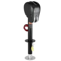
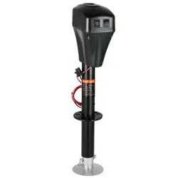
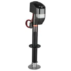
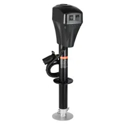
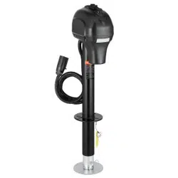
ELECTRIC TRAILER JACK
MODEL: EJ3500B
We continue to be committed to provide you tools with competitive price.
"Save Half", "Half Price" or any other similar expressions used by us only represents an
estimate of savings you might benefit from buying certain tools with us compared to the major
top brands and doses not necessarily mean to cover all categories of tools offered by us. You
are kindly reminded to verify carefully when you are placing an order with us if you are
actually saving half in comparison with the top major brands.

- 1 -
MODEL:EJ3500B
Have product questions? Need technical support? Please feel free to
contact us:
CustomerService@vevor.com
NEED HELP? CONTACT US!
This is the original instruction, please read all manual instructions
carefully before operating. VEVOR reserves a clear interpretation of our
user manual. The appearance of the product shall be subject to the
product you received. Please forgive us that we won't inform you again if
there are any technology or software updates on our product.
ELECTRIC TRAILER JACK

- 2 -
SAFETY INSTRUCTIONS
1. The “WARNING” symbol above is a sign that a service or
maintenance procedure has a safety risk involved and may cause
death or serious injury if not performed safely and within the
parameters set forth in this manual.
2. Always wear eye protection when performing service or maintenance
to the vehicle. Other safety equipment to consider would be hearing
protection, gloves and possibly a full face shield, depending on the
nature of the service.
3. Never allow anyone unfamiliar with this product to install, operate or
service this product.
4. Never lift or level the trailer without a properly installed footpad.
5. Never crank the jack or couple the trailer without preventing the trailer
from rolling.
6. Never exert excessive side forces to the trailer jack.
7. Never allow anyone, including the operator, to put any body parts
under the trailer jack or the supported load during jack operation.
8. Never exceed the load capacity !
9. Never use trailer jack to lift the trailer for service or tire change.
10. Never move the trailer before the trailer jack is fully retracted.
11. Keep children and bystanders away from the work area while
operating the tool. Do not allow children to handle the jack.
12. Do not use the jack where there is a risk of causing a fire or an
explosion; e.g., in the presence of flammable liquids, gases, or dust.
The jack can create sparks, which may ignite the flammable liquids,
gases, or dust.
13. For use on flat, level, hard surface capable of supporting load.
14. Do not use blocks for additional ground clearance.
15. When using the drop foot or drop leg, make certain the supplied pin is
fully inserted through both sides of the inner tube and the drop tube
before using the jack.
16. If the trailer jack has a drop leg, never attempt to adjust the drop leg

- 3 -
when there is any load on the jack.
Note:
1. The jack is designed for vertical movement of the trailer only.
2. Rapid and continuous lifting is not recommended to avoid gear
heating and reduce service life.
MODEL AND PARAMETERS
Model
EJ3500B
Capacity
3500 lbs
Input
DC 12V
Maximum Current
30A
Maximum Power
350W
Mounting Bracket Type
A-Frame Mounting Bracket
Range
9.8-33.8"
Screw Travel
18.11"
Drop Leg Travel
5.9"(4-hole)
The Distance between The
Two Holes in Drop Leg
1.968"
Height of Mounting
Support from
Ground(1-hole)
9.8"(lowest) / 28"(highest)
Lifting Time
113±2s
Outer /Inner Tube Dia.
2-1/4" (Black) / 2" (Zinc)
Foot Size
5-1/2" (Round)
Minimum Product Height
29.92"(Total Product Height)

- 4 -
STRUCTURE DIAGRAM
1.Top Cover
2.Lift Switch
3.Light Switch
4.LED Lamp
5.Fuse
6.Mounting Fittings
7.Wire(+)
8.Foot Plate
9.Pin
1
2
4
5
3
6
8
9
7

- 2 -
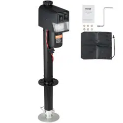
COMPONENTS
No.
Picture
Name
Qty
1
Electric Trailer Jack
1
2
Hand Rocker
1
3
Lock Washers
3
4
Washers
3
5
Waterproof Sunshade Bag
1
6
User Manual
1
ASSEMBLY
1. When mounting trailer jack, it is best to hook up to the tow vehicle to
make sure the trailer is secure.
Note:The concave surface
must face down.Sawtooth
must break the spray layer
and contact the metal surface
well !
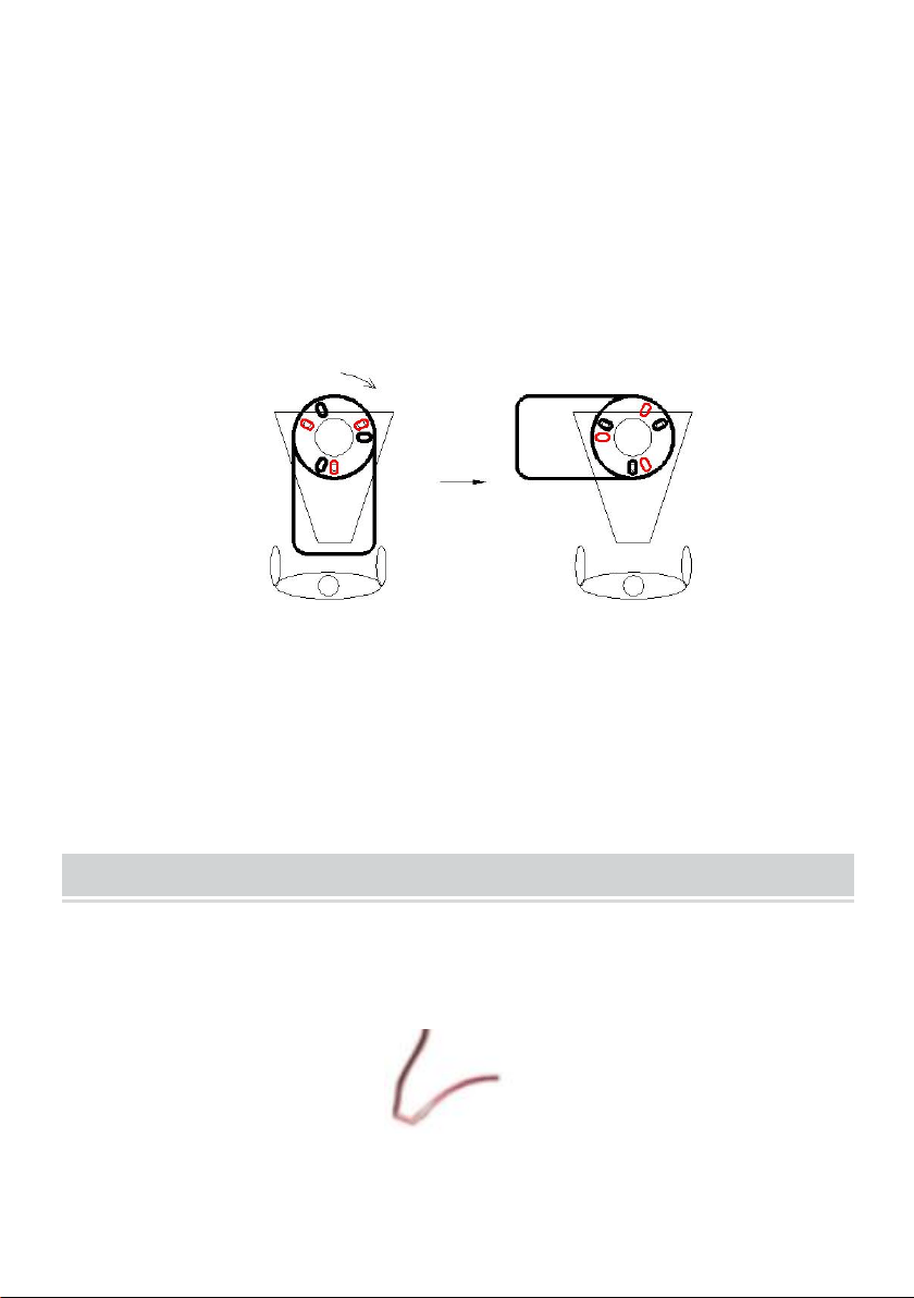
- 3 -
2. Mount jack based on drawing shown above.
3. Slide A-frame jack through hole on top of A-frame coupler.
4. Line up the three slotted holes on jack mounting plate to the three
holes in the coupler.
5. With three bolts and nuts (sold separately) secure jack tightly to the
top of the a-frame coupler. (Regularly check to ensure bolts/nuts are
tightened securely.)
6. After the jack is mounted to trailer, attach the handle assembly to jack
with bolt fastener provided.
Note: Select mounting holes as required.(Figure above)
OPERATION
1.Connect the red positive terminal to the positive terminal of the DC12V
Battery.
overlooking
Rotate 90 (Clockwise)
+(DC12V)

- 4 -
2.Inching to test light switch and up and down switch.
3.Install foot plate after lifting to appropriate height.
4.Lower the foot plate onto a hard floor/pad.
5.If necessary, remove the top cover and lift the jack manually.
Light Switch
Lift Switch
Top Cover

- 5 -
TROUBLESHOOTING
Failure
Possible Cause
Corrective Action
Motor will not
operate.
No or low voltage.
Check battery and electrical
connections. Must have minimum of
10 VDC. If the battery is low, plug the
trailer cable into the tow vehicle, and
start the tow vehicle to provide power
to the jack.
Poor grounding.
Clean area between the jack
mounting plate and coupler, and
ensure paint has been removed by
the star washers.
Direct metal-to-metal contact
must exist between mounting
components to ensure good electrical
contact.
Loose wires on
ON/OFF switch.
Secure wire connections.
ON/OFF switch is
Replace switch.
Faulty motor.
Replace motor.
Light doesn’t
work.
Loose wires on the
ON/OFF switch.
Secure wire connection.
Bad light bulb.
Replace bulb.

- 6 -
MAINTENANCE
1. Occasional cleaning with mild soap and water along with light oil
lubrication of pivot points will prolong peak performance and
appearance.
2. Periodically check whether the screws are loose.
3. Before each use, inspect jack tubes and replace if bent or damaged.
4. If wiring is connected to battery terminal, inspect at least twice each
year for corrosion. Clean with a solution of baking soda and water,
and then apply a thin coat of grease.
5. The motor’s ground screw and mounting bolts must be cleaned if a
grounding continuity problem occurs.
6. Maintain the product by adopting a program of conscientious repair
and maintenance in accordance with the following recommended
procedures. It is recommended that the general condition of any tool
be examined before it is used. Keep your tool in good repair. Keep
handles dry, clean, and free from oil and grease. The following chart is
based on a normal operation schedule.

- 7 -
Maintenance Interval
Maintenance Point
Daily before operating
1.The powered A-frame jack motor is sealed and
maintenancefree.
2.Before each use, inspect jack tubes and replace if
bent or damaged.
3.Ensure all connections are tight and free of
corrosion and that the jack is properly ground with the
coupler (metal to metal contact).
4.If necessary, wash with mild soap and water and
rinse thoroughly. The motor ground screw and
mounting bolts must also be cleaned if a ground
continuity problem occurs.
After the first 20
operating hours
Fully extend the jack and clean the inner jack tube.
After the first 50
operating hours or
every week
Fully extend the jack and clean the inner jack tube.
Every year
Fully extend the jack and clean the inner jack tube
once per year. After cleaning, coat the tube with a
light grease or silicone spray lubricant.