
Technical Support and E-Warranty Certificate
www.vevor.com/support
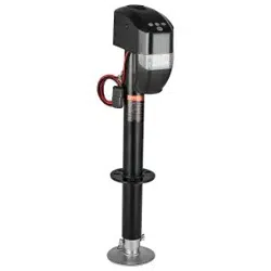
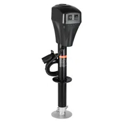
ELECTRIC TRAILER JACK
MODEL: EJ5075B-PL
We continue to be committed to provide you tools with competitive price.
"Save Half", "Half Price" or any other similar expressions used by us only represents an
estimate of savings you might benefit from buying certain tools with us compared to the major
top brands and does not necessarily mean to cover all categories of tools offered by us. You
are kindly reminded to verify carefully when you are placing an order with us if you are
actually saving half in comparison with the top major brands.

- 1 -
MODEL:EJ5075B-PL
Have product questions? Need technical support? Please feel free to
contact us:
Technical Support and E-Warranty Certificate
www.vevor.com/support
NEED HELP? CONTACT US!
This is the original instruction, please read all manual instructions
carefully before operating. VEVOR reserves a clear interpretation of our
user manual. The appearance of the product shall be subject to the
product you received. Please forgive us that we won't inform you again if
there are any technology or software updates on our product.
ELECTRIC TRAILER JACK

- 2 -
SAFETY INSTRUCTIONS
1. The “WARNING” symbol above is a sign that a service or
maintenance procedure involves a safety risk and may cause death or
serious injury if not performed safely and within the parameters set
forth in this manual.
2. Always wear eye protection when performing service or maintenance
to the vehicle. Other safety equipment to consider would be hearing
protection, gloves and possibly a full face shield, depending on the
nature of the service.
3. Never allow anyone unfamiliar with this product to install, operate or
service this product.
4. Never lift or level the trailer without a properly installed footpad.
5. Never crank the jack or couple the trailer without preventing the trailer
from rolling.
6. Never exert excessive side forces on the trailer jack.
7. Never allow anyone, including the operator, to put any body parts
under the trailer jack or the supported load during jack operation.
8. Never exceed the load capacity !
9. Never use trailer jack to lift the trailer for service or tire change.
10. Never move the trailer before the trailer jack is fully retracted.
11. Keep children and bystanders away from the work area while
operating the tool. Do not allow children to handle the jack.
12. Do not use the jack where there is a risk of causing a fire or an
explosion; e.g., in the presence of flammable liquids, gases, or dust.
The jack can create sparks, which may ignite the flammable liquids,
gases, or dust.
13. For use on flat, level, hard surface capable of supporting load.
14. Do not use blocks for additional ground clearance.
15. When using the drop foot or drop leg, make certain the supplied pin is
fully inserted through both sides of the inner tube and the drop tube
before using the jack.
16. If the trailer jack has a drop leg, never attempt to adjust the drop leg

- 3 -
when there is any load on the jack.
Note:
1. The jack is designed for vertical movement of the trailer only.
2. Rapid and continuous lifting is not recommended to avoid gear
heating and reduce service life.
This product is subject to the provision of European Directive 2012/19/EC. The
symbol showing a crossed-out wheeled bin indicates that the product requires
separate refuse collection in the European Union. This symbol applies to the
product and all accessories marked with this symbol. Products marked as such
may not be discarded with normal domestic waste but must be taken to a
collection point for recycling electrical and electronic devices.
MODEL AND PARAMETERS
Model
EJ5075B-PL
Max. Capacity
5000 lbs
Input
DC 12V
Maximum Current
29
±
1A
Maximum Power
350W
Mounting Bracket Type
A-Frame Mounting Bracket
Range
10-33.8"
Screw Travel
18.3"
Drop Leg Travel
5.5"(4-hole)
The Distance between The
Two Holes in Drop Leg
1.85"
- 4 -
Height of Mounting
Support from
Ground(1-hole)
10"(lowest) / 28.3"(highest)
Lifting Time
180±2s(on-load)
Outer /Inner Tube Dia.
2-1/4" (Black) / 2" (Zinc)
Foot Size
5.5" (Round)
Minimum Product Height
29"(Total Product Height)
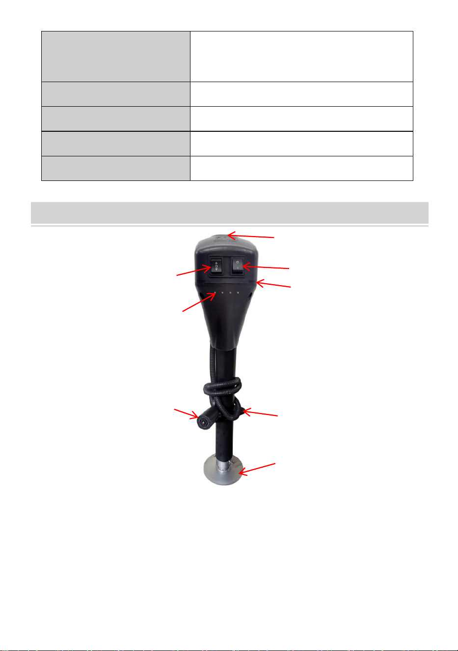
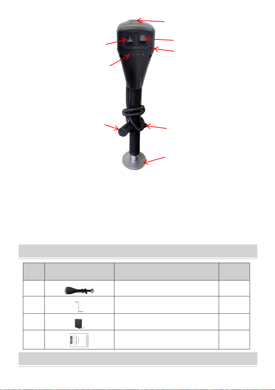
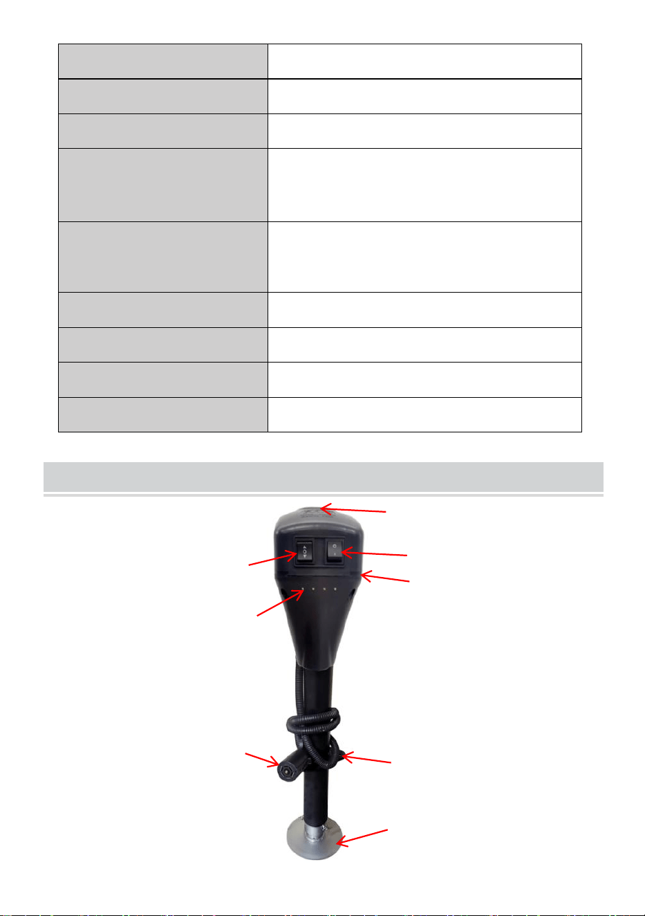
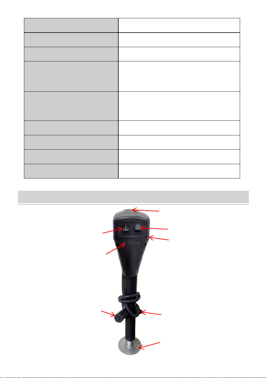
STRUCTURE DIAGRAM
1.Up & Down Switch
2.Rubber Cap over Manual Crank
Access
3.Light Switch
4. Plastic cover
5. LED light
6.7-way Plug
7.Mounting Plate
8.Extension Foot Pad
5
1
2
3
4
6
7
8
- 5 -
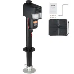
COMPONENTS
No.
Picture
Name
Qty
1
Electric Trailer Jack
1
2
Manual Crank Handle
1
3
Waterproof Sunshade Bag
1
4
User Manual
1
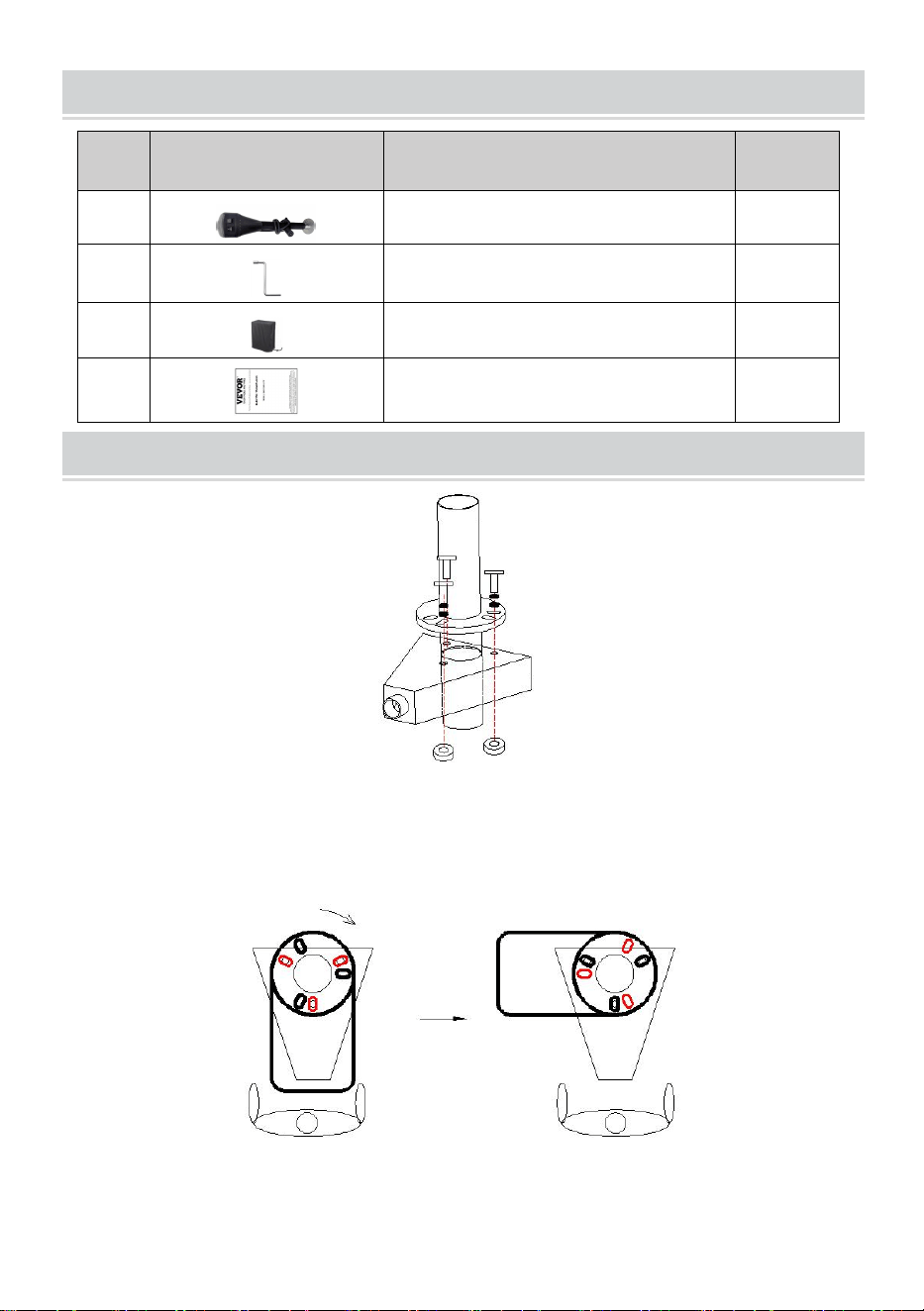
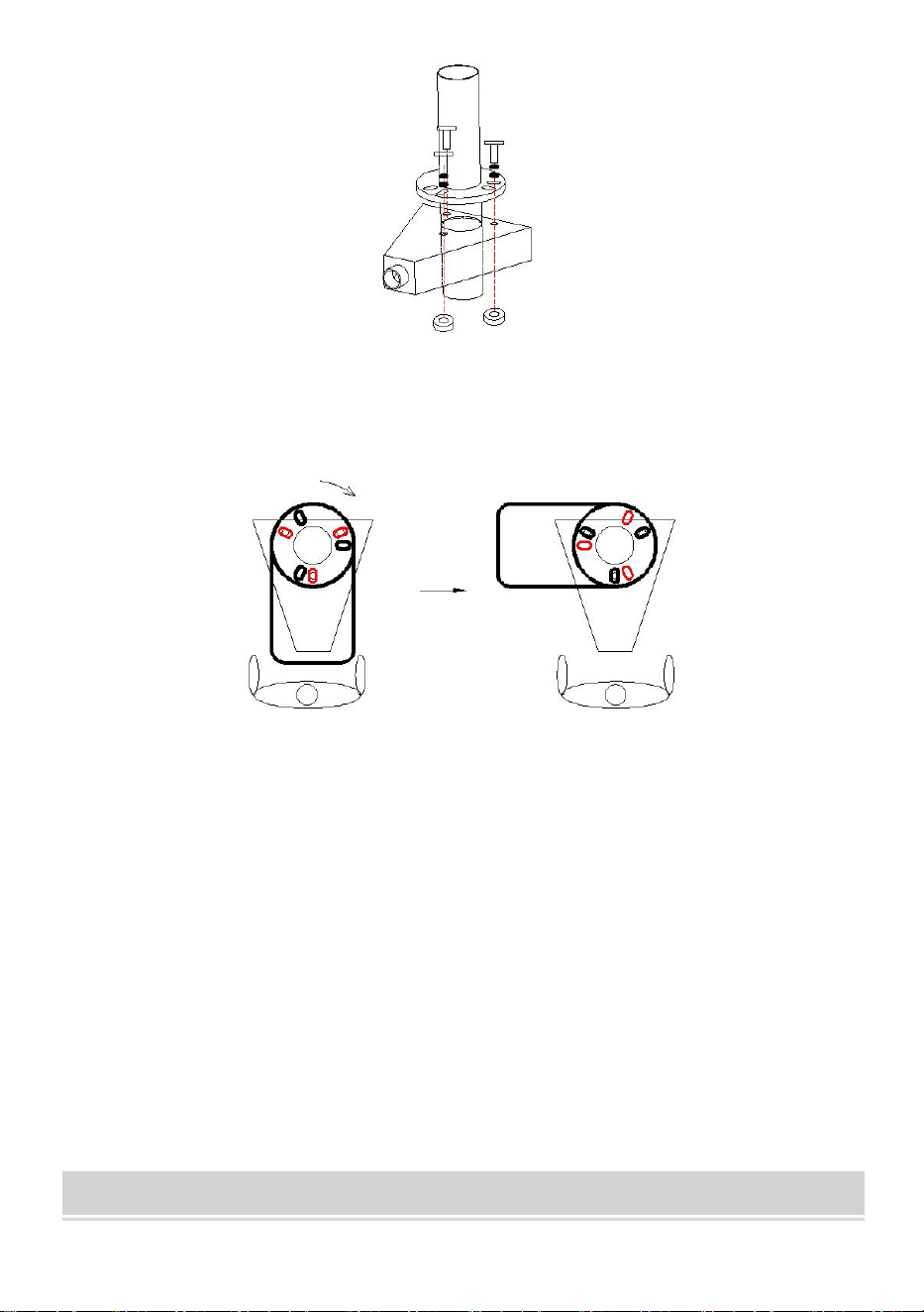
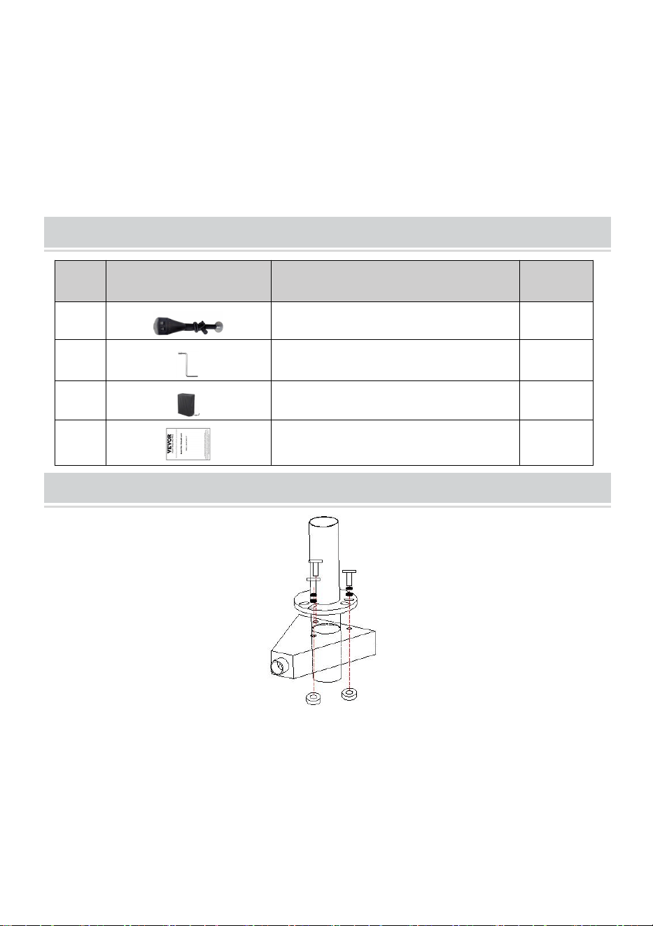
ASSEMBLY
1. When mounting trailer jack, it is best to hook it up to the tow vehicle to
make sure the trailer is secure.
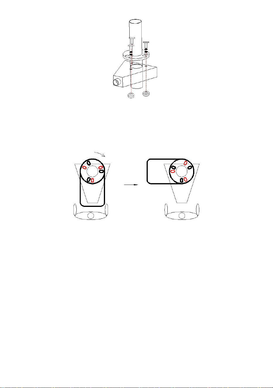
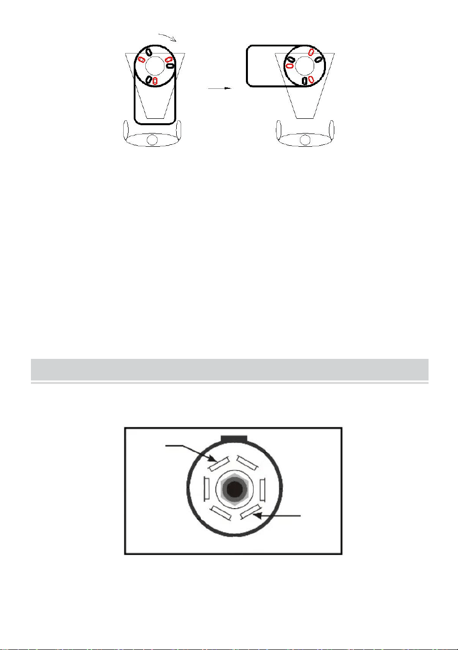
2. Mount jack based on drawing shown above. The Motor orientation
can be selected as shown below.
Note: Select mounting holes as required.(Figure above)
overlooking
Rotate 90 (Clockwise)
- 6 -
3. Slide A-frame jack through hole on top of A-frame coupler.
4. Line up the three slotted holes on jack mounting plate to the three
holes in the coupler.
5. With three bolts and nuts (Must be purchased by the user.) secure
jack tightly to the top of the a-frame coupler. (Regularly check to
ensure bolts/nuts are tightened securely.)
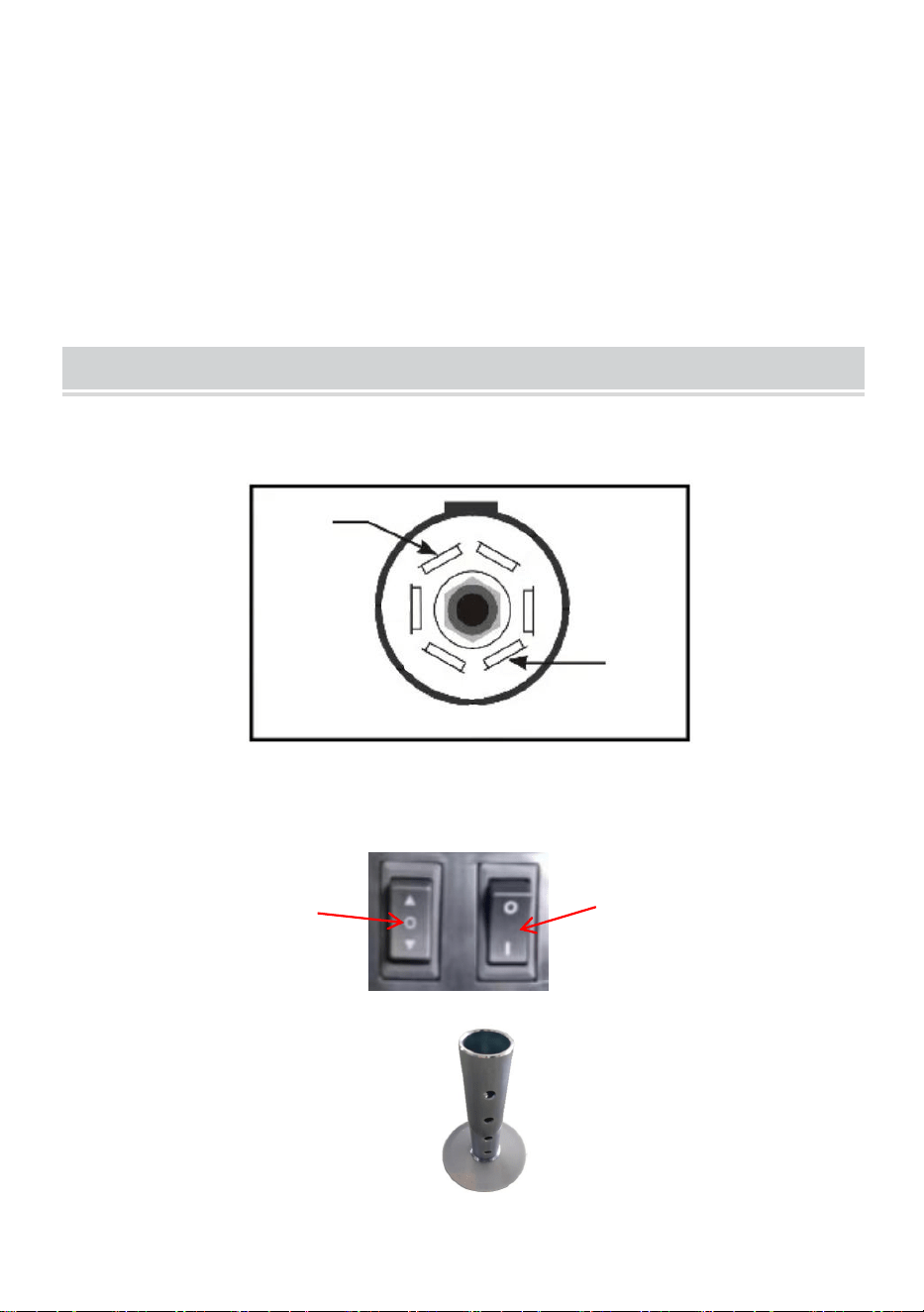
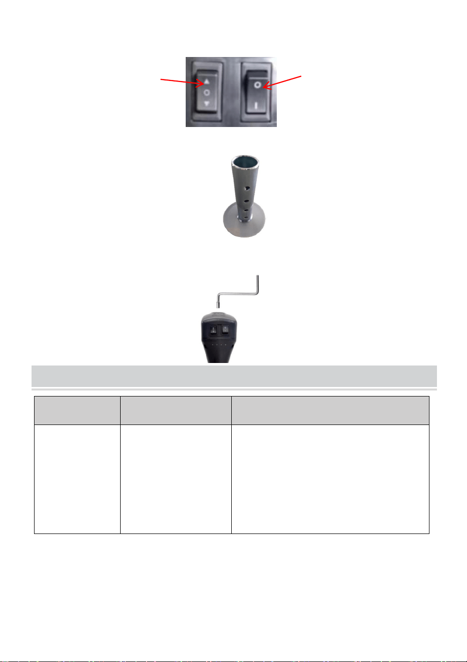
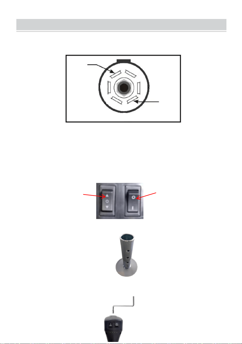
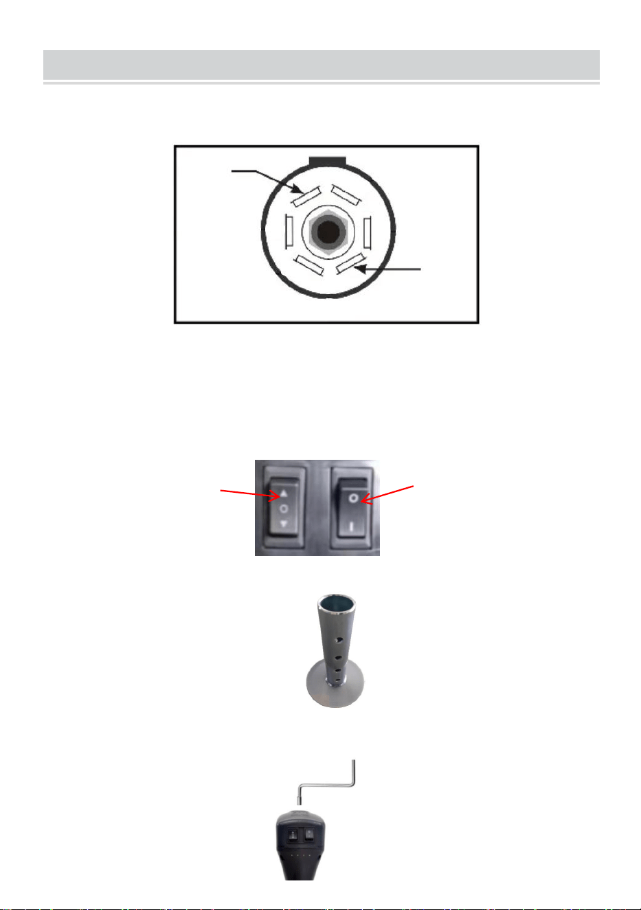
OPERATION
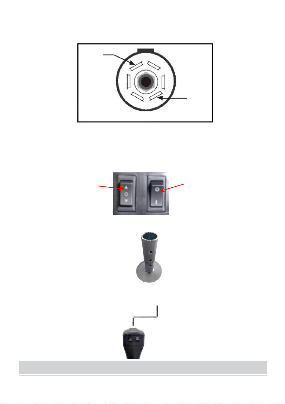
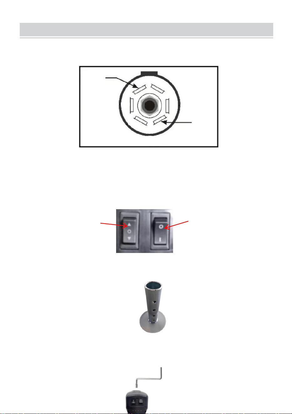
1. The input voltage of this product is DC12V, and the 7-star plug is
positive/ground as shown below.
Warning: Be sure to note that the ground wire corresponds to the ground
wire of the 7-star plug on the car! If not, adjust the wiring by yourself !
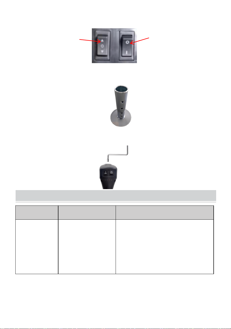
2. Inching to test light switch and up and down switch.
3.Install foot plate after lifting it to appropriate height.
4.Lower the foot plate onto a hard floor/pad.
GND
VCC +
Lift Switch
Light Switch

- 7 -
5.If necessary, remove the rubber cover and manually pull up the dry catty
top.
TROUBLESHOOTING
Failure
Possible Cause
Corrective Action
Motor will not
operate.
No or low voltage.
Check battery and electrical
connections. Must have minimum of
10 VDC. If the battery is low, plug the
trailer cable into the tow vehicle, and
start the tow vehicle to provide power
to the jack.
Poor grounding.
Clean area between the jack
mounting plate and coupler, and
ensure paint has been removed by
the star washers.
Direct metal-to-metal contact
must exist between mounting
components to ensure good electrical
contact.
Loose wires on
ON/OFF switch.
Secure wire connections.
ON/OFF switch is
Replace switch.
Faulty motor.
Replace motor.
Light doesn’t
work.
Loose wires on the
ON/OFF switch.
Secure wire connection.
Bad light bulb.
Replace bulb.

- 8 -
MAINTENANCE
1. Occasional cleaning with mild soap and water along with light oil
lubrication of pivot points will prolong peak performance and
appearance.
2. Periodically check whether the screws are loose.
3. Before each use, inspect jack tubes and replace them if bent or
damaged.
4. If wiring is connected to battery terminal, inspect at least twice each
year for corrosion. Clean with a solution of baking soda and water,
and then apply a thin coat of grease.
5. Maintain the product by adopting a program of conscientious repair
and maintenance in accordance with the following recommended
procedures. It is recommended that the general condition of any tool
be examined before it is used. Keep your tool in good repair. Keep
handles dry, clean, and free from oil and grease. The following chart is
based on a normal operation schedule.

- 9 -
Maintenance Interval
Maintenance Point
Daily before operating
1.The powered A-frame jack motor is sealed and
maintenance-free.
2.Before each use, inspect jack tubes and replace
them if bent or damaged.
3.Ensure all connections are tight and free of
corrosion and that the jack is properly ground with the
coupler (metal-to-metal contact).
4.If necessary, wash with mild soap and water and
rinse thoroughly. The motor ground screw and
mounting bolts must also be cleaned if a ground
continuity problem occurs.
After the first 20
operating hours
Fully extend the jack and clean the inner jack tube.
After the first 50
operating hours or
every week
Fully extend the jack and clean the inner jack tube.
Every year
Fully extend the jack and clean the inner jack tube
once per year. After cleaning, coat the tube with a
light grease or silicone spray lubricant.


Assistance technique et certificat de garantie électronique
www.vevor.com/support
CRIC DE REMORQUE ÉLECTRIQUE
MODÈLE : EJ5075B-PL
We continue to be committed to provide you tools with competitive price.
"Save Half", "Half Price" or any other similar expressions used by us only represents an
estimate of savings you might benefit from buying certain tools with us compared to the major
top brands and does not necessarily mean to cover all categories of tools offered by us. You
are kindly reminded to verify carefully when you are placing an order with us if you are
actually saving half in comparison with the top major brands.

- 1 -
MODÈLE : EJ5075B-PL
Have product questions? Need technical support? Please feel free to
contact us:
Technical Support and E-Warranty Certificate
www.vevor.com/support
NEED HELP? CONTACT US!
This is the original instruction, please read all manual instructions
carefully before operating. VEVOR reserves a clear interpretation of our
user manual. The appearance of the product shall be subject to the
product you received. Please forgive us that we won't inform you again if
there are any technology or software updates on our product.
ELECTRIC TRAILER JACK

- 2 -
SAFETY INSTRUCTIONS
17. Le symbole « AVERTISSEMENT » ci-dessus est un signe qu'une
procédure d'entretien ou de maintenance comporte un risque de
sécurité et peut entraîner la mort ou des blessures graves si elle n'est
pas effectuée en toute sécurité et dans les paramètres définis dans ce
manuel.
18. Portez toujours une protection pour les yeux lorsque vous effectuez
des travaux d'entretien ou de maintenance sur le véhicule. D'autres
équipements de sécurité à prendre en compte sont une protection
auditive, des gants et éventuellement un écran facial complet, selon
la nature de l'entretien.
19. Ne laissez jamais une personne non familière avec ce produit installer,
utiliser ou entretenir ce produit.
20. Ne soulevez ou ne nivelez jamais la remorque sans un repose-pied
correctement installé.
21. Ne jamais actionner le cric ni atteler la remorque sans empêcher la
remorque de rouler.
22. N’exercez jamais de forces latérales excessives sur le cric de la
remorque .
23. Ne laissez jamais personne, y compris l'opérateur, placer une partie
du corps sous le cric de la remorque ou sous la charge supportée
pendant le fonctionnement du cric.
24. Ne jamais dépasser la capacité de charge !
25. N'utilisez jamais de cric de remorque pour soulever la remorque en
vue d'un entretien ou d'un changement de pneu.
26. Ne déplacez jamais la remorque avant que le cric de la remorque ne
soit complètement rétracté.
27. Tenez les enfants et les personnes présentes à l'écart de la zone de
travail pendant l'utilisation de l'outil. Ne laissez pas les enfants
manipuler le cric.
28. N'utilisez pas le cric dans des endroits où il existe un risque d'incendie
ou d'explosion, par exemple en présence de liquides, de gaz ou de

- 3 -
poussières inflammables. Le cric peut créer des étincelles qui
peuvent enflammer les liquides, les gaz ou les poussières
inflammables.
29. À utiliser sur une surface plane, horizontale et dure capable de
supporter une charge.
30. N'utilisez pas de blocs pour augmenter la garde au sol.
31. Lorsque vous utilisez le pied ou la jambe de force, assurez-vous que
la goupille fournie est complètement insérée dans les deux côtés du
tube intérieur et du tube de force avant d'utiliser le cric .
32. Si le cric de remorque est équipé d'un pied de support, n'essayez
jamais de régler ce dernier lorsqu'une charge est placée sur le cric.
Note:
3. Le cric est conçu pour le mouvement vertical de la remorque
uniquement.
4. Un levage rapide et continu n'est pas recommandé pour éviter
l'échauffement des engrenages et réduire leur durée de vie .
Ce produit est soumis aux dispositions de la directive européenne 2012/19/CE.
Le symbole représentant une poubelle à roulettes barrée indique que le produit
doit être collecté séparément dans l'Union européenne. Ce symbole s'applique au
produit et à tous les accessoires marqués de ce symbole. Les produits marqués
comme tels ne doivent pas être jetés avec les ordures ménagères normales mais
doit être emmené à un point de collecte pour le recyclage des appareils
électriques et électroniques.
MODEL AND PARAMETERS
Modèle
EJ5075B-PL
Capacité max.
5000 livres
Saisir
12 V CC

- 4 -
Courant maximal
29±1A
Puissance maximale
350 W
Type de support de
montage
Support de montage en A
Gamme
10 -3 3,8 "
Vis de déplacement
18,3 "
Voyage à jambe
tombante
5,5 " (4 trous)
La distance entre les deux
trous dans la jambe
tombante
1,85 "
Hauteur du support de
montage à partir du sol (1
trou)
10 " (le plus bas) / 28,3 " (le plus haut)
Temps de levage
1 80 ±2 s (en charge)
Diamètre
extérieur/intérieur du tube
2-1/4" (noir) / 2" (zinc)
Taille du pied
5,5" (rond)
Hauteur minimale du
produit
29" (hauteur totale du produit)
STRUCTURE DIAGRAM
2
- 5 -
1. Interrupteur haut et bas
2. Capuchon en caoutchouc sur
l'accès manuel à la manivelle
3. Interrupteur d'éclairage
4. Couvercle en plastique
5. Lumière LED
Fiche à 6,7 voies
7.Plaque de montage
8. Coussinet de pied extensible
COMPONENTS
Non
.
Image
Nom
Quantit
é
1
Cric de remorque électrique
1
2
Manivelle manuelle
1
3
Sac imperméable S unshade
1
4
Manuel d'utilisation
1
ASSEMBLY
5
1
3
4
6
7
8
- 6 -
6. Lors du montage du cric de remorque, il est préférable de l' accrocher
au véhicule tracteur pour s'assurer que la remorque est sécurisée.
7. Montez le cric en fonction du schéma ci-dessus . L' orientation du
moteur peut être sélectionnée comme indiqué ci-dessous .
Remarque : sélectionnez les trous de montage selon vos besoins. (Figure
ci-dessus)
8. Faites glisser le cric du cadre en A à travers le trou situé sur le dessus
du coupleur du cadre en A.
9. Alignez les trois trous fendus de la plaque de montage du cric avec
les trois trous du coupleur.
10. Avec trois boulons et écrous (doivent être achetés par l'utilisateur . )
Fixez fermement le cric au sommet du coupleur à cadre en A.
(Vérifiez régulièrement que les boulons/écrous sont bien serrés.)
OPERATION
overlooking
Rotate 90 (Clockwise)
- 7 -
3. La tension d'entrée de ce produit est de 12 V CC et la prise 7 étoiles est
positive/terre comme indiqué ci-dessous.
Attention : Attention, le fil de terre correspond au fil de terre de la prise 7
étoiles de la voiture ! Sinon, ajustez le câblage vous-même !
4. Avancement pour tester l'interrupteur d'éclairage et l'interrupteur
haut/bas.
3. Installez le repose-pieds après l' avoir soulevé à la hauteur appropriée.
4. Abaissez le repose-pieds sur un sol dur/un coussin.
5. Si nécessaire, retirez le couvercle en caoutchouc et soulevez
manuellement le dessus du bac sec.
TROUBLESHOOTING
GND
VCC +
Lift Switch
Light Switch

- 8 -
Échec
Cause possible
Mesures correctives
Le moteur ne
fonctionne
pas.
Pas ou peu de
tension.
Vérifiez la batterie et les connexions
électriques. Elle doit avoir un
minimum de 10 V CC. Si la batterie
est faible, branchez le câble de la
remorque sur le véhicule tracteur et
démarrer le véhicule tracteur pour
alimenter le cric.
Mauvaise mise à la
terre.
Nettoyez la zone entre la plaque de
montage du cric et le coupleur et
assurez-vous que la peinture a été
enlevé par les rondelles en étoile.
Contact métal sur métal direct
doit exister entre les composants de
montage pour assurer une bonne
électricité
contact.
Fils desserrés sur
l'interrupteur
marche/arrêt.
Connexions de fils sécurisées.
L'interrupteur
Remplacer l'interrupteur.
Moteur défectueux.
Remplacer le moteur.
La lumière ne
fonctionne
pas.
Fils desserrés sur le
Interrupteur
marche/arrêt.
Connexion filaire sécurisée.
Mauvaise ampoule.
Remplacer l'ampoule.
MAINTENANCE
6. Un nettoyage occasionnel avec du savon doux et de l'eau ainsi
qu'une lubrification légère à l'huile des points de pivot prolongeront les
performances et l'apparence optimales.
7. Vérifiez régulièrement si les vis sont desserrées.
8. Avant chaque utilisation, inspectez les tubes du cric et remplacez- les
s'ils sont pliés ou endommagés.

- 9 -
9. Si le câblage est connecté à la borne de la batterie, inspectez-le au
moins deux fois par an pour corrosion. Nettoyer avec une solution de
bicarbonate de soude et d'eau, puis appliquer une fine couche de
graisse.
10. Entretenez le produit en adoptant un programme de réparation et
d'entretien consciencieux conformément aux procédures
recommandées suivantes. Il est recommandé d'examiner l'état
général de tout outil avant de l'utiliser. Maintenez votre outil en bon
état. Gardez les poignées sèches, propres et exemptes d'huile et de
graisse. Le tableau suivant est basé sur un programme de
fonctionnement normal.

- 10 -
Intervalle de
Point d'entretien
Quotidiennement avant
l'opération
1. Le moteur du vérin à cadre en A motorisé est
scellé et sans entretien .
2. Avant chaque utilisation, inspectez les tubes du
cric et remplacez- les s'ils sont pliés ou
endommagés.
3. Assurez-vous que toutes les connexions sont
serrées et exemptes de corrosion et que le cric est
correctement mis à la terre avec le coupleur (contact
métal sur métal ) .
4. Si nécessaire, lavez avec de l'eau et du savon
doux et rincez abondamment. La vis de mise à la
terre du moteur et les boulons de montage doivent
également être nettoyé si un problème de continuité
Après les 20 premières
heures de
fonctionnement
Déployez complètement le cric et nettoyez le tube
intérieur du cric.
Après les 50 premières
heures de
fonctionnement ou
chaque semaine
Déployez complètement le cric et nettoyez le tube
intérieur du cric.
Chaque année
Déployez complètement le cric et nettoyez le tube
intérieur du cric une fois par an. Après le nettoyage,
enduisez le tube d'une graisse légère ou d'un
lubrifiant en spray au silicone.


Technischer Support und E-Garantie-Zertifikat
www.vevor.com/support
ELEKTRISCHE ANHÄNGERSTÜTZE
MODELL: EJ5075B-PL
We continue to be committed to provide you tools with competitive price.
"Save Half", "Half Price" or any other similar expressions used by us only represents an
estimate of savings you might benefit from buying certain tools with us compared to the major
top brands and does not necessarily mean to cover all categories of tools offered by us. You
are kindly reminded to verify carefully when you are placing an order with us if you are
actually saving half in comparison with the top major brands.

- 1 -
MODELL: EJ5075B-PL
Have product questions? Need technical support? Please feel free to
contact us:
Technical Support and E-Warranty Certificate
www.vevor.com/support
NEED HELP? CONTACT US!
This is the original instruction, please read all manual instructions
carefully before operating. VEVOR reserves a clear interpretation of our
user manual. The appearance of the product shall be subject to the
product you received. Please forgive us that we won't inform you again if
there are any technology or software updates on our product.
ELECTRIC TRAILER JACK

- 2 -
SAFETY INSTRUCTIONS
33. Das oben stehende Symbol „ WARNUNG “ weist darauf hin, dass ein
Service- oder Wartungsvorgang ein Sicherheitsrisiko birgt und zum
Tod oder zu schweren Verletzungen führen kann, wenn er nicht sicher
und innerhalb der in diesem Handbuch festgelegten Parameter
durchgeführt wird.
34. Tragen Sie bei Wartungs- oder Instandhaltungsarbeiten am Fahrzeug
immer einen Augenschutz. Weitere zu berücksichtigende
Sicherheitsausrüstung sind Gehörschutz, Handschuhe und je nach
Art der Wartung möglicherweise ein Vollgesichtsschutz.
35. Erlauben Sie niemals jemandem, der mit diesem Produkt nicht
vertraut ist, die Installation, Bedienung oder Wartung dieses Produkts.
36. Heben Sie den Anhänger niemals an oder nivellieren Sie ihn, ohne
dass eine ordnungsgemäß installierte Fußplatte vorhanden ist.
37. Betätigen Sie niemals die Stütze oder kuppeln Sie den Anhänger an,
ohne ihn am Wegrollen zu hindern.
38. Üben Sie niemals übermäßige seitliche Kräfte auf die Stütze des
Anhängers aus .
39. während des Wagenheberbetriebs Körperteile unter den Wagenheber
oder die getragene Last zu bringen .
40. Die zulässige Tragkraft darf auf keinen Fall überschritten werden !
41. Verwenden Sie niemals einen Anhängerheber, um den Anhänger für
Wartungsarbeiten oder zum Reifenwechsel anzuheben.
42. Bewegen Sie den Anhänger niemals, bevor die Stütze vollständig
eingefahren ist.
43. Halten Sie Kinder und andere Personen während der Arbeit mit dem
Werkzeug vom Arbeitsbereich fern. Erlauben Sie Kindern nicht, den
Wagenheber zu bedienen.
44. Verwenden Sie den Wagenheber nicht, wenn die Gefahr eines
Brandes oder einer Explosion besteht, z. B. in der Nähe von
brennbaren Flüssigkeiten, Gasen oder Staub. Der Wagenheber kann
Funken erzeugen, die brennbare Flüssigkeiten, Gase oder Staub

- 3 -
entzünden können.
45. Zur Verwendung auf flachen, ebenen, harten und tragfähigen
Flächen.
46. Verwenden Sie keine Blöcke für zusätzliche Bodenfreiheit.
47. Wenn Sie den Fallfuß oder das Fallbein verwenden, stellen Sie sicher,
dass der mitgelieferte Stift vollständig durch beide Seiten des
Innenrohrs und des Fallrohrs eingeführt ist, bevor Sie den
Wagenheber verwenden .
48. Wenn der Wagenheber über ein Ausfallende verfügt, versuchen Sie
niemals, das Ausfallende einzustellen, wenn auf dem Wagenheber
eine Last lastet .
Notiz:
5. Der Wagenheber ist nur für die vertikale Bewegung des Anhängers
ausgelegt.
6. Schnelles und kontinuierliches Anheben wird nicht empfohlen, da sich
das Getriebe sonst überhitzen und die Lebensdauer verkürzt .
Dieses Produkt unterliegt den Bestimmungen der europäischen Richtlinie
2012/19/EG. Das Symbol einer durchgestrichenen Mülltonne weist darauf hin,
dass das Produkt in der Europäischen Union einer getrennten Müllentsorgung
unterliegt. Dieses Symbol gilt für das Produkt und alle mit diesem Symbol
gekennzeichneten Zubehörteile. So gekennzeichnete Produkte dürfen nicht mit
dem normalen Hausmüll entsorgt werden. sondern muss zu einem Sammelstelle
für das Recycling von elektrischen und elektronischen Geräten.
MODEL AND PARAMETERS
Modell
EJ5075B-PL
Max. Kapazität
5000 Pfund
Eingang
Gleichstrom 12 V

- 4 -
Maximaler Strom
29 ± 1 A
Maximale Leistung
350 W
Typ der Montagehalterung
A-Rahmen-Montagehalterung
Reichweite
10 -3 3,8 "
Schraube Reise
18,3 "
Drop - Leg - Federweg
5,5 " (4-Loch)
Der Abstand zwischen den
beiden Löchern im Drop Leg
1,85 "
Höhe der Montagehalterung
vom Boden ( 1 -Loch )
10 " (niedrigste) / 28,3 " (höchste)
Hebezeit
1 80 ±2 s (unter Last)
Außen-/Innenrohrdurchmesser.
2-1/4" (Schwarz) / 2" (Zink)
Fußgröße
5,5" (rund)
Minimale Produkthöhe
29" (Gesamtprodukthöhe)
STRUCTURE DIAGRAM
2

- 5 -
1. Auf- und Ab-Schalter
2. Gummikappe über dem
manuellen Kurbelzugang
3.Lichtschalter
4. Kunststoffabdeckung
5. LED-Licht
6,7-poliger Stecker
7.Montageplatte
8. Verlängerungsfußpolster
COMPONENTS
NEI
N.
Bild
Name
Menge
1
Elektrischer Anhängerheber
1
2
Manuelle Kurbel
1
3
Wasserdichte
Sonnenschutztasche
1
4
Bedienungsanleitung
1
ASSEMBLY
5
1
3
4
6
7
8
- 6 -
11. Beim Anbringen einer Anhängerstütze ist es am besten, diese am
Zugfahrzeug anzukoppeln, um die Sicherheit des Anhängers zu
gewährleisten.
12. Montieren Sie die Buchse gemäß der oben gezeigten Zeichnung . Die
Motorausrichtung kann wie unten gezeigt ausgewählt werden .
Hinweis: Wählen Sie die Befestigungslöcher nach Bedarf aus. (Abbildung
oben)
13. Schieben Sie den A-Rahmen-Wagenheber durch das Loch oben auf
der A-Rahmen-Kupplung.
14. Richten Sie die drei Langlöcher auf der Wagenhebermontageplatte an
den drei Löchern in der Kupplung aus.
15. Mit drei Schrauben und Muttern (müssen vom Benutzer gekauft
werden . ) Befestigen Sie den Wagenheber fest an der Oberseite der
A-Rahmenkupplung. (Überprüfen Sie regelmäßig, ob die
Schrauben/Muttern fest angezogen sind.)
overlooking
Rotate 90 (Clockwise)
- 7 -
OPERATION
5. Die Eingangsspannung dieses Produkts beträgt DC12V und der
7-Sterne-Stecker ist positiv/geerdet, wie unten gezeigt.
Achtung: Achten Sie unbedingt darauf, dass das Massekabel mit dem
Massekabel des 7-Stern-Steckers am Fahrzeug übereinstimmt! Wenn
nicht, passen Sie die Verkabelung selbst an!
6. Langsam fahren, um den Lichtschalter und den Auf- und Ab-Schalter
zu testen.
3.Installieren Sie die Fußplatte, nachdem Sie sie auf die entsprechende
Höhe angehoben haben.
4. Senken Sie die Fußplatte auf einen harten Boden/eine harte Unterlage
ab.
5. Falls erforderlich, entfernen Sie die Gummiabdeckung und ziehen Sie
das trockene Catty-Oberteil manuell hoch.
GND
VCC +
Lift Switch
Light Switch

- 8 -
TROUBLESHOOTING
Versagen
Mögliche Ursache
Korrekturmaßnahme
Motor
funktioniert
nicht.
Keine oder niedrige
Spannung.
Überprüfen Sie die Batterie und die
elektrischen Anschlüsse. Mindestens
10 VDC erforderlich. Wenn die
Batterie schwach ist, stecken Sie das
Anhängerkabel in das Zugfahrzeug
und
Starten Sie das Zugfahrzeug, um den
Schlechte Erdung.
Reinigen Sie den Bereich zwischen
der Wagenheber-Montageplatte und
der Kupplung und stellen Sie sicher,
dass die Farbe wurde durch die
Sternscheiben entfernt .
Direkter Metall-Metall-Kontakt
zwischen den
Befestigungselementen muss eine
gute elektrische
Lose Kabel am
EIN/AUS-Schalter.
Sichere Kabelverbindungen.
Der
Schalter ersetzen.
Defekter Motor.
Motor ersetzen.
Licht
funktioniert
nicht .
Lose Drähte an der
EIN/AUS-Schalter.
Sichere Kabelverbindung.
Defekte Glühbirne.
Glühlampe ersetzen.
MAINTENANCE
11. Gelegentliches Reinigen mit milder Seife und Wasser sowie eine

- 9 -
leichte Ölschmierung der Drehpunkte verlängern die Spitzenleistung
und das Erscheinungsbild.
12. Überprüfen Sie regelmäßig, ob die Schrauben locker sind.
13. Überprüfen Sie vor jedem Gebrauch die Wagenheberrohre und
ersetzen Sie sie , wenn sie verbogen oder beschädigt sind.
14. Wenn die Verkabelung an die Batterieklemme angeschlossen ist,
überprüfen Sie mindestens zweimal jährlich, ob Korrosion. Mit einer
Lösung aus Backpulver und Wasser reinigen und anschließend eine
dünne Schicht Fett auftragen.
15. Warten Sie das Produkt, indem Sie ein Programm gewissenhafter
Reparatur- und Wartungsarbeiten gemäß den folgenden empfohlenen
Verfahren durchführen. Es wird empfohlen, den allgemeinen Zustand
jedes Werkzeugs vor der Verwendung zu prüfen. Halten Sie Ihr
Werkzeug in gutem Zustand. Halten Sie die Griffe trocken, sauber
und frei von Öl und Fett. Die folgende Tabelle basiert auf einem
normalen Betriebsplan.

- 10 -
Wartungsintervall
Wartungspunkt
Täglich vor dem Betrieb
1. Der angetriebene A-Rahmenhebermotor ist
versiegelt und wartungsfrei .
2. Überprüfen Sie vor jedem Gebrauch die
Wagenheberrohre und ersetzen Sie sie , wenn sie
verbogen oder beschädigt sind.
3. Stellen Sie sicher, dass alle Verbindungen fest und
korrosionsfrei sind und dass die Buchse
ordnungsgemäß mit der Kupplung geerdet ist (Metall
- Metall - Kontakt).
4. Falls erforderlich, mit milder Seife und Wasser
waschen und gründlich abspülen . Die
Motorerdungsschraube und die
Befestigungsschrauben müssen ebenfalls gereinigt,
Nach den ersten 20
Betriebsstunden
Fahren Sie den Wagenheber vollständig aus und
reinigen Sie das innere Wagenheberrohr.
Nach den ersten 50
Betriebsstunden oder
jede Woche
Fahren Sie den Wagenheber vollständig aus und
reinigen Sie das innere Wagenheberrohr.
Jährlich
Fahren Sie den Wagenheber einmal jährlich
vollständig aus und reinigen Sie das innere
Wagenheberrohr . Beschichten Sie das Rohr nach
der Reinigung mit einem leichten Schmierfett oder


Supporto tecnico e certificato di garanzia elettronica
www.vevor.com/support
CRIC ELETTRICO PER RIMORCHIO
MODELLO: EJ5075B-PL
We continue to be committed to provide you tools with competitive price.
"Save Half", "Half Price" or any other similar expressions used by us only represents an
estimate of savings you might benefit from buying certain tools with us compared to the major
top brands and does not necessarily mean to cover all categories of tools offered by us. You
are kindly reminded to verify carefully when you are placing an order with us if you are
actually saving half in comparison with the top major brands.

- 1 -
MODELLO: EJ5075B-PL
Have product questions? Need technical support? Please feel free to
contact us:
Technical Support and E-Warranty Certificate
www.vevor.com/support
NEED HELP? CONTACT US!
This is the original instruction, please read all manual instructions
carefully before operating. VEVOR reserves a clear interpretation of our
user manual. The appearance of the product shall be subject to the
product you received. Please forgive us that we won't inform you again if
there are any technology or software updates on our product.
ELECTRIC TRAILER JACK

- 2 -
SAFETY INSTRUCTIONS
49. Il simbolo " ATTENZIONE " sopra riportato indica che una procedura
di assistenza o manutenzione comporta un rischio per la sicurezza e
può causare morte o lesioni gravi se non eseguita in modo sicuro e
secondo i parametri stabiliti nel presente manuale.
50. Indossare sempre una protezione per gli occhi quando si esegue un
servizio o una manutenzione sul veicolo. Altri dispositivi di sicurezza
da considerare sono la protezione dell'udito, i guanti e, possibilmente,
una visiera completa, a seconda della natura del servizio.
51. Non consentire mai a chiunque non abbia familiarità con questo
prodotto di installarlo, utilizzarlo o eseguirne la manutenzione.
52. Non sollevare o livellare mai il rimorchio senza il poggiapiedi
correttamente installato.
53. Non azionare mai il cric o agganciare il rimorchio senza impedirne lo
spostamento.
54. Non esercitare mai forze laterali eccessive sul cric del rimorchio .
55. Non consentire mai a nessuno, compreso l'operatore, di posizionare
parti del corpo sotto il cric del rimorchio o sotto il carico sostenuto
durante il funzionamento del cric.
56. Non superare mai la capacità di carico !
57. Non utilizzare mai il cric per sollevare il rimorchio a scopo di
manutenzione o sostituzione degli pneumatici.
58. Non spostare mai il rimorchio prima che il cric sia completamente
retratto.
59. Tenere bambini e astanti lontani dall'area di lavoro mentre si utilizza
l'utensile. Non consentire ai bambini di maneggiare il martinetto.
60. Non utilizzare il martinetto in luoghi in cui vi sia il rischio di provocare
un incendio o un'esplosione; ad esempio, in presenza di liquidi, gas o
polvere infiammabili. Il martinetto può creare scintille, che possono
incendiare i liquidi, i gas o la polvere infiammabili.
61. Da utilizzare su superfici piane, livellate e dure in grado di sostenere
carichi.

- 3 -
62. Non utilizzare blocchi per aumentare l'altezza libera dal suolo.
63. Quando si utilizza il piede di caduta o la gamba di caduta, assicurarsi
che il perno in dotazione sia completamente inserito attraverso
entrambi i lati del tubo interno e del tubo di caduta prima di utilizzare il
martinetto .
64. Se il cric del rimorchio è dotato di un piede di sollevamento, non
tentare mai di regolarlo quando il cric è carico .
Nota:
7. Il martinetto è progettato esclusivamente per lo spostamento verticale
del rimorchio.
8. Si sconsiglia il sollevamento rapido e continuo per evitare il
surriscaldamento degli ingranaggi e ridurne la durata utile .
Questo prodotto è soggetto alle disposizioni della Direttiva europea 2012/19/CE.
Il simbolo raffigurante un bidone della spazzatura barrato indica che il prodotto
richiede la raccolta differenziata dei rifiuti nell'Unione Europea. Questo simbolo si
applica al prodotto e a tutti gli accessori contrassegnati con questo simbolo. I
prodotti contrassegnati come tali non possono essere smaltiti con i normali rifiuti
domestici ma deve essere portato a un punto di raccolta per il riciclaggio di
apparecchiature elettriche ed elettroniche.
MODEL AND PARAMETERS
Modello
EJ5075B-PL
Capacità massima
5000 libbre
Ingresso
Corrente continua 12V
Corrente massima
29
±
1A
Potenza massima
350W
Tipo di staffa di
montaggio
Staffa di montaggio a telaio ad A
- 4 -
Allineare
10 -3 3,8 "
Vite di viaggio
18,3 "
Viaggio a gambe
cadenti
5,5 " (4 fori)
La distanza tra i due fori
nel drop leg
1,85 "
Altezza del supporto di
montaggio da terra ( 1
foro)
10 " (minimo) / 28,3 " (massimo)
Tempo di sollevamento
1 80 ±2 s (sotto carico)
Diametro tubo
esterno/interno.
2-1/4" (Nero) / 2" (Zinco)
Misura del piede
5,5" (rotondo)
Altezza minima del
prodotto
29" (altezza totale del prodotto)
STRUCTURE DIAGRAM
5
1
2
3
4
6
7
8
- 1 -
1. Interruttore su e giù
2. Tappo in gomma sopra
l'accesso alla manovella manuale
3.Interruttore della luce
4. Copertura in plastica
5. Luce LED
Spina a 6,7 vie
7. Piastra di montaggio
8. Estensione del cuscinetto per il
piede
COMPONENTS
NO.
Immagine
Nome
Quantit
à
1
Jack elettrico per rimorchio
1
2
Manovella manuale
1
3
Borsa impermeabile anti - UV
1
4
Manuale d'uso
1
ASSEMBLY
16. Quando si monta il cric per rimorchio, è meglio agganciarlo al veicolo
trainante per garantire la sicurezza del rimorchio.
17. Montare il martinetto in base al disegno mostrato sopra . L'
orientamento del motore può essere selezionato come mostrato di
seguito .

- 2 -
Nota: selezionare i fori di montaggio in base alle esigenze (figura sopra).
18. Far scorrere il martinetto a telaio ad A attraverso il foro nella parte
superiore dell'accoppiatore a telaio ad A.
19. Allineare i tre fori asolati sulla piastra di montaggio del martinetto con i
tre fori nell'accoppiatore.
20. Con tre Bulloni e dadi (devono essere acquistati dall'utente ) Fissare
saldamente il martinetto alla parte superiore dell'accoppiatore a telaio.
(Controllare regolarmente che i bulloni/dadi siano serrati saldamente.)
OPERATION
7. La tensione di ingresso di questo prodotto è DC12V e la spina a 7 stelle
è positiva/terra come mostrato di seguito.
Attenzione: assicurati che il filo di terra corrisponda al filo di terra della
spina a 7 stelle dell'auto! In caso contrario, regola il cablaggio da solo!
8. Avanzamento lento per testare l'interruttore della luce e l'interruttore di
overlooking
Rotate 90 (Clockwise)
GND
VCC +
- 3 -
salita e discesa.
3. Installare la pedana dopo averla sollevata all'altezza appropriata.
4. Abbassare la pedana su un pavimento/cuscinetto duro.
5. Se necessario, rimuovere la copertura in gomma e sollevare
manualmente la parte superiore del catty asciutto.
TROUBLESHOOTING
Fallimento
Possibile causa
Azione correttiva
Il motore non
funziona.
Nessuna o bassa
tensione.
Controllare la batteria e i collegamenti
elettrici. Deve avere almeno 10 VDC.
Se la batteria è scarica, collegare il
cavo del rimorchio al veicolo di traino
e
avviare il veicolo di traino per fornire
energia al cric.
Lift Switch
Light Switch

- 4 -
Scarsa messa a
terra.
Pulisci l'area tra la piastra di
montaggio del martinetto e
l'accoppiatore e assicurati che la
vernice è stato rimosso dalle rondelle
a stella.
Contatto diretto metallo-metallo
deve esistere tra i componenti di
montaggio per garantire una buona
elettricità
Cavi allentati
sull'interruttore
ON/OFF.
Collegamenti dei cavi sicuri.
L'interruttore
Sostituire l'interruttore.
Motore difettoso.
Sostituire il motore.
La luce non
funziona.
Fili allentati sul
Interruttore
ON/OFF.
Collegamento sicuro dei cavi.
Lampadina
difettosa.
Sostituire la lampadina.
MAINTENANCE
16. Una pulizia occasionale con acqua e sapone neutro, insieme a una
leggera lubrificazione con olio dei punti di snodo, ne prolungherà le
prestazioni ottimali e l'aspetto.
17. Controllare periodicamente che le viti siano allentate.
18. Prima di ogni utilizzo, ispezionare i tubi del martinetto e sostituirli se
piegati o danneggiati.
19. Se il cablaggio è collegato al terminale della batteria, ispezionarlo
almeno due volte all'anno per corrosione. Pulire con una soluzione di
bicarbonato di sodio e acqua, quindi applicare uno strato sottile di
grasso.
20. Mantenere il prodotto adottando un programma di riparazione e
manutenzione coscienziose in conformità con le seguenti procedure
consigliate. Si raccomanda di esaminare le condizioni generali di
qualsiasi utensile prima di utilizzarlo. Mantenere l'utensile in buone

- 5 -
condizioni. Mantenere le impugnature asciutte, pulite e prive di olio e
grasso. La seguente tabella si basa su un normale programma di
funzionamento.

- 6 -
Intervallo di
Punto di manutenzione
Ogni giorno prima
dell'operazione
1. Il motore del martinetto a telaio ad A è sigillato e
senza manutenzione .
2. Prima di ogni utilizzo, ispezionare i tubi del
martinetto e sostituirli se piegati o danneggiati.
3. Assicurarsi che tutti i collegamenti siano ben saldi
e privi di corrosione e che il martinetto sia
correttamente messo a terra con l'accoppiatore
(contatto metallo - metallo ).
4. Se necessario, lavare con acqua e sapone neutro
e risciacquare abbondantemente. Anche la vite di
messa a terra del motore e i bulloni di montaggio
devono essere pulito se si verifica un problema di
continuità di terra.
Dopo le prime 20 ore di
funzionamento
Estendere completamente il cric e pulire il tubo
interno.
Dopo le prime 50 ore di
funzionamento o ogni
settimana
Estendere completamente il cric e pulire il tubo
interno.
Ogni anno
Estendere completamente il martinetto e pulire il tubo
interno del martinetto una volta all'anno . Dopo la
pulizia, ricoprire il tubo con un leggero grasso o
lubrificante spray al silicone.


Soporte técnico y certificado de garantía electrónica
www.vevor.com/support
GATO DE REMOLQUE ELÉCTRICO
MODELO: EJ5075B-PL
We continue to be committed to provide you tools with competitive price.
"Save Half", "Half Price" or any other similar expressions used by us only represents an
estimate of savings you might benefit from buying certain tools with us compared to the major
top brands and does not necessarily mean to cover all categories of tools offered by us. You
are kindly reminded to verify carefully when you are placing an order with us if you are
actually saving half in comparison with the top major brands.

- 1 -
MODELO: EJ5075B-PL
Have product questions? Need technical support? Please feel free to
contact us:
Technical Support and E-Warranty Certificate
www.vevor.com/support
NEED HELP? CONTACT US!
This is the original instruction, please read all manual instructions
carefully before operating. VEVOR reserves a clear interpretation of our
user manual. The appearance of the product shall be subject to the
product you received. Please forgive us that we won't inform you again if
there are any technology or software updates on our product.
ELECTRIC TRAILER JACK

- 2 -
SAFETY INSTRUCTIONS
65. El símbolo de “ ADVERTENCIA ” que aparece arriba es una señal de
que un procedimiento de servicio o mantenimiento implica un riesgo
de seguridad y puede causar la muerte o lesiones graves si no se
realiza de manera segura y dentro de los parámetros establecidos en
este manual.
66. Utilice siempre protección para los ojos al realizar tareas de
mantenimiento o servicio en el vehículo. Otros equipos de seguridad
que se deben tener en cuenta son la protección auditiva, los guantes
y, posiblemente, una pantalla facial completa, según la naturaleza del
servicio.
67. Nunca permita que alguien que no esté familiarizado con este
producto instale, opere o realice mantenimiento del mismo.
68. Nunca levante ni nivele el remolque sin una plataforma para pies
correctamente instalada.
69. Nunca gire el gato ni acople el remolque sin impedir que éste se
mueva.
70. Nunca ejerza fuerzas laterales excesivas sobre el gato del remolque .
71. Nunca permita que nadie, incluido el operador, coloque partes del
cuerpo debajo del gato del remolque o de la carga soportada durante
el funcionamiento del gato.
72. ¡Nunca exceda la capacidad de carga !
73. Nunca use el gato del remolque para levantar el remolque para
realizar tareas de mantenimiento o cambiar neumáticos.
74. Nunca mueva el remolque antes de que el gato del remolque esté
completamente retraído.
75. Mantenga a los niños y a las personas que se encuentren cerca del
área de trabajo mientras utiliza la herramienta. No permita que los
niños manipulen el gato.
76. No utilice el gato en lugares donde exista riesgo de incendio o
explosión, por ejemplo, en presencia de líquidos, gases o polvos
inflamables. El gato puede generar chispas que pueden encender los

- 3 -
líquidos, gases o polvos inflamables.
77. Para utilizar en superficies planas, niveladas y duras capaces de
soportar carga.
78. No utilice bloques para obtener mayor distancia al suelo.
79. Al utilizar el pie o la pata de caída, asegúrese de que el pasador
provisto esté completamente insertado a través de ambos lados del
tubo interior y del tubo de caída antes de usar el gato .
80. Si el gato del remolque tiene una pata abatible, nunca intente
ajustarla cuando haya alguna carga sobre el gato.
Nota:
9. El gato está diseñado únicamente para el movimiento vertical del
remolque.
10. No se recomienda una elevación rápida y continua para evitar el
calentamiento del engranaje y reducir la vida útil .
Este producto está sujeto a las disposiciones de la Directiva Europea 2012/19/CE.
El símbolo que muestra un contenedor de basura tachado indica que el producto
requiere una recogida selectiva de residuos en la Unión Europea. Este símbolo
se aplica al producto y a todos los accesorios marcados con este símbolo. Los
productos marcados como tales no pueden desecharse con los residuos
domésticos normales. pero debe ser llevado a un Punto de recogida para el
reciclaje de aparatos eléctricos y electrónicos.
MODEL AND PARAMETERS
Modelo
EJ5075B-PL
Capacidad máxima
5000 libras
Aporte
12 V CC
Corriente máxima
29
±
1 A

- 4 -
Máxima potencia
350 W
Tipo de soporte de
montaje
Soporte de montaje en forma de A
Rango
10 -3 3,8 "
Viaje de tornillo
18,3 "
Viaje con piernas caídas
5,5 " (4 orificios)
La distancia entre los dos
agujeros en la pata de
caída
1,85 "
Altura del soporte de
montaje desde el suelo ( 1
orificio)
10 " (más bajo) / 28,3 " (más alto)
Tiempo de elevación
1 80 ±2 s (bajo carga)
Diámetro del tubo
exterior/interior.
2-1/4" (negro) / 2" (zinc)
Tamaño del pie
5,5" (redondo)
Altura mínima del
producto
29" (Altura total del producto)
STRUCTURE DIAGRAM
2

- 5 -
1.Interruptor arriba y abajo
2. Tapa de goma sobre el acceso a
la manivela manual
3.Interruptor de luz
4. Cubierta de plástico
5. Luz LED
Enchufe de 6,7 vías
7.Placa de montaje
8. Almohadilla de extensión para
pies
COMPONENTS
No.
Imagen
Nombre
Cantid
ad
1
Gato eléctrico para remolque
1
2
Manivela manual
1
3
Bolsa parasol impermeable
1
4
Manual de usuario
1
ASSEMBLY
5
1
3
4
6
7
8

- 6 -
21. Al montar el gato del remolque, es mejor engancharlo al vehículo
remolcador para asegurarse de que el remolque esté seguro.
22. Monte el conector según el dibujo que se muestra arriba . La
orientación del motor se puede seleccionar como se muestra a
continuación .
Nota: Seleccione los orificios de montaje según sea necesario. (Figura
anterior)
23. Deslice el gato en forma de A a través del orificio en la parte superior
del acoplador en forma de A.
24. Alinee los tres orificios ranurados de la placa de montaje del gato con
los tres orificios del acoplador.
25. Con tres Pernos y tuercas (debe adquirirlos el usuario ) que fijan
firmemente el gato a la parte superior del acoplador del bastidor en A.
(Verifique regularmente que los pernos y las tuercas estén bien
apretados).
overlooking
Rotate 90 (Clockwise)
- 7 -
OPERATION
9. El voltaje de entrada de este producto es DC12V y el enchufe de 7
estrellas es positivo/tierra como se muestra a continuación.
Advertencia: ¡Asegúrese de tener en cuenta que el cable de tierra
corresponde al cable de tierra del enchufe de 7 estrellas del automóvil! Si
no es así, ajuste el cableado usted mismo.
10. Avanzando lentamente para probar el interruptor de luz y el
interruptor de subida y bajada.
3. Instale la placa del pie después de levantarla a la altura adecuada.
4. Baje la placa para los pies sobre un piso o una almohadilla dura.
5. Si es necesario, retire la cubierta de goma y levante manualmente la
parte superior seca del gato.
GND
VCC +
Lift Switch
Light Switch

- 8 -
TROUBLESHOOTING
Falla
Posible causa
Acción correctiva
El motor no
funciona.
Ningún voltaje o
voltaje bajo.
Revise la batería y las conexiones
eléctricas. Debe tener un mínimo de
10 VCC. Si la batería está baja,
conecte el cable del remolque al
vehículo remolcador y
Arranque el vehículo remolcador para
proporcionar energía al gato.
Mala conexión a
tierra.
Limpie el área entre la placa de
montaje del gato y el acoplador, y
asegúrese de que la pintura Ha sido
eliminado por las arandelas de
estrella.
Contacto directo metal con metal
Debe existir entre los componentes
de montaje para garantizar una
buena conexión eléctrica.
Cables sueltos en el
interruptor de
encendido/apagado.
Conexiones de cables seguras.
El interruptor de
Reemplazar el interruptor.
Motor defectuoso.
Reemplazar el motor.
La luz no
funciona.
Cables sueltos en el
Interruptor de
encendido y
Conexión de cable segura.
Bombilla
defectuosa.
Reemplace la bombilla.
MAINTENANCE
21. La limpieza ocasional con agua y jabón suave junto con una ligera
lubricación con aceite de los puntos de pivote prolongará el máximo

- 9 -
rendimiento y la apariencia.
22. Compruebe periódicamente si los tornillos están flojos.
23. Antes de cada uso, inspeccione los tubos del gato y reemplácelos si
están doblados o dañados.
24. Si el cableado está conectado al terminal de la batería, inspecciónelo
al menos dos veces al año para verificar que no haya daños.
corrosión. Limpiar con una solución de bicarbonato de sodio y agua y
luego aplicar una fina capa de grasa.
25. Realice el mantenimiento del producto adoptando un programa de
reparación y mantenimiento minucioso de acuerdo con los siguientes
procedimientos recomendados. Se recomienda examinar el estado
general de cualquier herramienta antes de utilizarla. Mantenga la
herramienta en buen estado. Mantenga los mangos secos, limpios y
libres de aceite y grasa. El siguiente cuadro se basa en un programa
de funcionamiento normal.

- 10 -
Intervalo de
Punto de mantenimiento
Diariamente antes de
operar
1. El motor del gato con bastidor en A eléctrico está
sellado y libre de mantenimiento .
2. Antes de cada uso, inspeccione los tubos del gato
y reemplácelos si están doblados o dañados.
3. Asegúrese de que todas las conexiones estén
firmes y libres de corrosión y que el gato esté
correctamente conectado a tierra con el acoplador
(contacto de metal con metal ) .
4. Si es necesario, lave con agua y jabón suave y
enjuague bien. El tornillo de conexión a tierra del
motor y los pernos de montaje también deben estar
Limpiado si ocurre un problema de continuidad de
tierra.
Después de las
primeras 20 horas de
funcionamiento
Extienda completamente el gato y limpie el tubo
interior del gato.
Después de las
primeras 50 horas de
funcionamiento o cada
semana
Extienda completamente el gato y limpie el tubo
interior del gato.
Cada año
Extienda completamente el gato y limpie el tubo
interior del gato una vez al año. Después de
limpiarlo, cubra el tubo con una grasa ligera o un
lubricante en aerosol de silicona.


Wsparcie techniczne i certyfikat e-gwarancji
www.vevor.com/support
PODNOŚNIK PRZYCZEPY
ELEKTRYCZNEJ
MODEL: EJ5075B-PL
We continue to be committed to provide you tools with competitive price.
"Save Half", "Half Price" or any other similar expressions used by us only represents an
estimate of savings you might benefit from buying certain tools with us compared to the major
top brands and does not necessarily mean to cover all categories of tools offered by us. You
are kindly reminded to verify carefully when you are placing an order with us if you are
actually saving half in comparison with the top major brands.

- 1 -
MODEL: EJ5075B-PL
Have product questions? Need technical support? Please feel free to
contact us:
Technical Support and E-Warranty Certificate
www.vevor.com/support
NEED HELP? CONTACT US!
This is the original instruction, please read all manual instructions
carefully before operating. VEVOR reserves a clear interpretation of our
user manual. The appearance of the product shall be subject to the
product you received. Please forgive us that we won't inform you again if
there are any technology or software updates on our product.
ELECTRIC TRAILER JACK

- 2 -
SAFETY INSTRUCTIONS
81. Symbol „ OSTRZEŻENIE ” powyżej oznacza, że procedura
serwisowa lub konserwacyjna wiąże się z ryzykiem dla bezpieczeń
stwa i może spowodować śmierć lub poważne obrażenia, jeśli nie
zostanie wykonana bezpiecznie i zgodnie z parametrami określonymi
w niniejszej instrukcji.
82. Zawsze zakładaj okulary ochronne podczas wykonywania serwisu lub
konserwacji pojazdu. Innym sprzętem bezpieczeństwa, który należy
wziąć pod uwagę, są ochronniki słuchu, rękawice i ewentualnie pełna
osłona twarzy, w zależności od charakteru serwisu.
83. Nigdy nie pozwalaj osobom niezaznajomionym z tym produktem na
instalację, obsługę lub serwisowanie tego produktu.
84. Nigdy nie podnoś i nie poziomuj przyczepy bez prawidłowo
zamontowanej podnóżka.
85. Nigdy nie należy uruchamiać podnośnika ani podłączać przyczepy
bez zabezpieczenia jej przed stoczeniem się.
86. Nigdy nie wywieraj nadmiernych sił bocznych na podnośnik
przyczepy .
87. Nigdy nie pozwalaj nikomu, łącznie z operatorem, na umieszczanie
jakichkolwiek części ciała pod podnośnikiem przyczepy lub
podtrzymywanym ładunkiem podczas obsługi podnośnika.
88. Nigdy nie przekraczaj dopuszczalnego udźwigu !
89. Nigdy nie używaj podnośnika przyczepy do podnoszenia przyczepy w
celu wykonania prac serwisowych lub wymiany opon.
90. Nigdy nie należy poruszać przyczepą, dopóki podnośnik przyczepy
nie zostanie całkowicie wsunięty.
91. Trzymaj dzieci i osoby postronne z dala od miejsca pracy podczas
obsługi narzędzia. Nie pozwalaj dzieciom obsługiwać podnośnika.
92. Nie używaj podnośnika w miejscach, w których istnieje ryzyko pożaru
lub wybuchu; np. w obecności łatwopalnych cieczy, gazów lub pyłów.
Podnośnik może wytwarzać iskry, które mogą zapalić łatwopalne

- 3 -
ciecze, gazy lub pyły.
93. Do stosowania na płaskiej, równej i twardej powierzchni, która może
unieść ciężar.
94. Nie należy stosować klocków w celu uzyskania dodatkowego
prześwitu.
95. W przypadku korzystania z opuszczanej stopy lub opuszczanej nogi,
przed użyciem podnośnika należy upewnić się, że dołączony sworzeń
jest całkowicie wsunięty przez obie strony rury wewnętrznej i rury
opuszczanej .
96. Jeśli podnośnik przyczepy jest wyposażony w opuszczaną nogę,
nigdy nie próbuj jej regulować, gdy na podnośniku znajduje się
jakikolwiek ładunek .
Notatka:
11. Podnośnik jest przeznaczony wyłącznie do pionowego
przemieszczania przyczepy.
12. Nie zaleca się szybkiego i ciągłego podnoszenia, aby uniknąć
nagrzewania się przekładni i skrócić jej żywotność .
Niniejszy produkt podlega postanowieniom Dyrektywy Europejskiej 2012/19/WE.
Symbol przedstawiający przekreślony kosz na śmieci na kółkach oznacza, że
produkt wymaga oddzielnej zbiórki odpadów w Unii Europejskiej. Ten symbol
dotyczy produktu i wszystkich akcesoriów oznaczonych tym symbolem.
Produktów oznaczonych w ten sposób nie można wyrzucać razem ze zwykłymi
odpadami domowymi. ale trzeba to zabrać do punkt zbiórki sprzętu elektrycznego
i elektronicznego przeznaczonego do recyklingu.
MODEL AND PARAMETERS
Model
EJ5075B-PL
Maksymalna pojemność
5000 funtów

- 4 -
Wejście
Prąd stały 12 V
Maksymalny prąd
29±1A
Maksymalna moc
350 W
Typ uchwytu
montażowego
Uchwyt montażowy ramy A
Zakres
10-3 3,8 "
Śruba Podróż
18,3 "
Podróż z obniżoną nogą
5,5 " (4 otwory)
Odległość między dwoma
otworami w Drop Leg
1,85 cala
Wysokość wspornika
montażowego od podłoża
( 1 otwór )
10 " (najniższy) / 28,3 " (najwyższy)
Czas podnoszenia
1 80 ±2 s (pod obciążeniem)
Średnica
zewnętrzna/wewnętrzna
2-1/4" (czarny) / 2" (cynk)
Rozmiar stopy
5,5" (okrągły)
Minimalna wysokość
produktu
29" (całkowita wysokość produktu)
STRUCTURE DIAGRAM
2

- 5 -
1. Przełącznik góra/dół
2. Gumowa nasadka nad ręczną
korbą
3. Przełącznik światła
4. Osłona plastikowa
5. Światło LED
Wtyczka 6,7-stykowa
7.Płyta montażowa
8. Podkładka rozszerzająca stopy
COMPONENTS
NIE.
Zdjęcie
Nazwa
Ilość
1
Elektryczny podnośnik
przyczepy
1
2
Korba ręczna
1
3
Wodoodporna torba S z
osłoną przeciwsłoneczną
1
4
Instrukcja obsługi
1
ASSEMBLY
5
1
3
4
6
7
8

- 6 -
26. Podczas montażu podnośnika przyczepy najlepiej jest podłączyć go
do pojazdu holującego, aby mieć pewność, że przyczepa jest
bezpieczna.
27. Zamontuj podnośnik na podstawie rysunku pokazanego powyżej .
Orientację silnika można wybrać, jak pokazano poniżej .
Uwaga: Wybierz otwory montażowe zgodnie z potrzebami. (Rysunek
powyżej)
28. Przesuń podnośnik ramy A przez otwór znajdujący się na górze
łącznika ramy A.
29. Dopasuj trzy otwory szczelinowe na płycie montażowej podnośnika
do trzech otworów w łączniku.
30. Z trzema Śruby i nakrętki (Muszą zostać zakupione przez
użytkownika . ) Mocno przymocuj podnośnik do górnej części łącznika
ramy w kształcie litery A. (Regularnie sprawdzaj, czy śruby/nakrętki są
dobrze dokręcone.)
overlooking
Rotate 90 (Clockwise)
- 7 -
OPERATION
11. Napięcie wejściowe tego produktu wynosi 12 V DC, a wtyczka
7-gwiazdkowa jest dodatnia/uziemiona, jak pokazano poniżej.
Ostrzeżenie: Pamiętaj, że przewód uziemiający odpowiada przewodowi
uziemiającemu wtyczki 7-gwiazdkowej w samochodzie! Jeśli nie, dostosuj
okablowanie samodzielnie!
12. Przesuwanie palcem w celu przetestowania przełącznika światła oraz
przełącznika góra/dół.
3. Zamontuj podnóżek po podniesieniu go na odpowiednią wysokość.
4. Opuść podnóżek na twardą podłogę/podkładkę.
5. W razie potrzeby zdejmij gumową osłonę i ręcznie podnieś suchą
pokrywę pojemnika.
GND
VCC +
Lift Switch
Light Switch

- 8 -
TROUBLESHOOTING
Awaria
Możliwa
przyczyna
Działanie naprawcze
Silnik nie
będzie
działał.
Brak napięcia lub
niskie napięcie.
Sprawdź akumulator i połączenia
elektryczne. Musi mieć co najmniej 10
VDC. Jeśli akumulator jest słaby,
podłącz kabel przyczepy do pojazdu
holowniczego i
uruchom pojazd holowniczy, aby
dostarczyć zasilanie do podnośnika.
Słabe uziemienie.
Wyczyść obszar między płytą
montażową podnośnika a sprzęgiem i
upewnij się, że farba jest czysta.
został usunięty przez podkładki
gwiazdowe.
Bezpośredni kontakt metalu z
metalem
musi istnieć pomiędzy elementami
montażowymi, aby zapewnić dobrą
Luźne przewody
przełącznika
WŁ./WYŁ.
Zabezpiecz połączenia przewodowe.
Przełącznik
Wymień przełącznik.
Wadliwy silnik.
Wymień silnik.
Światło nie
działa.
Luźne przewody na
Przełącznik
WŁ./WYŁ.
Bezpieczne połączenie przewodowe.
Zła żarówka.
Wymień żarówkę.
MAINTENANCE
26. Okresowe czyszczenie łagodnym mydłem i wodą oraz lekkie
smarowanie punktów obrotowych olejem przedłuży optymalną
wydajność i wygląd.

- 9 -
27. Sprawdzaj okresowo, czy śruby nie są poluzowane.
28. Przed każdym użyciem należy sprawdzić rury podnośnika i wymienić
je , jeśli są wygięte lub uszkodzone.
29. Jeżeli okablowanie jest podłączone do zacisku akumulatora, należy
przeprowadzać kontrolę co najmniej dwa razy w roku. korozja.
Oczyścić roztworem sody oczyszczonej i wody, a następnie nałożyć
cienką warstwę smaru.
30. Utrzymuj produkt, stosując program sumiennej naprawy i konserwacji
zgodnie z następującymi zalecanymi procedurami. Zaleca się
sprawdzenie ogólnego stanu każdego narzędzia przed jego użyciem.
Utrzymuj narzędzie w dobrym stanie. Utrzymuj uchwyty suche, czyste
i wolne od oleju i smaru. Poniższa tabela jest oparta na normalnym
harmonogramie pracy.

- 10 -
Interwał konserwacji
Punkt konserwacyjny
Codziennie przed
operacją
1. Silnik podnośnika A-frame jest uszczelniony i
konserwacja - bezobsługowa.
2. Przed każdym użyciem należy sprawdzić rury
podnośnika i wymienić je , jeśli są wygięte lub
uszkodzone.
3. Upewnij się, że wszystkie połączenia są szczelne i
nie są skorodowane, a podnośnik jest prawidłowo
uziemiony za pomocą łącznika (kontakt metal -
metal ).
4. W razie potrzeby umyj łagodnym mydłem i wodą i
dokładnie spłucz. Śruba uziemiająca silnika i śruby
mocujące muszą być również wyczyszczono, jeśli
występuje problem z ciągłością uziemienia.
Po pierwszych 20
godzinach pracy
Całkowicie rozłóż podnośnik i wyczyść wewnętrzną
rurę podnośnika.
Po pierwszych 50
godzinach pracy lub co
tydzień
Całkowicie rozłóż podnośnik i wyczyść wewnętrzną
rurę podnośnika.
Co roku
Całkowicie rozciągnij podnośnik i wyczyść
wewnętrzną rurę podnośnika raz w roku. Po
wyczyszczeniu pokryj rurę lekkim smarem lub
silikonowym środkiem smarnym w sprayu.


Technische ondersteuning en e-garantiecertificaat
www.vevor.com/support
ELEKTRISCHE AANHANGWAGEN KRIK
MODEL: EJ5075B-PL
We continue to be committed to provide you tools with competitive price.
"Save Half", "Half Price" or any other similar expressions used by us only represents an
estimate of savings you might benefit from buying certain tools with us compared to the major
top brands and does not necessarily mean to cover all categories of tools offered by us. You
are kindly reminded to verify carefully when you are placing an order with us if you are
actually saving half in comparison with the top major brands.

- 1 -
MODEL: EJ5075B-PL
Have product questions? Need technical support? Please feel free to
contact us:
Technical Support and E-Warranty Certificate
www.vevor.com/support
NEED HELP? CONTACT US!
This is the original instruction, please read all manual instructions
carefully before operating. VEVOR reserves a clear interpretation of our
user manual. The appearance of the product shall be subject to the
product you received. Please forgive us that we won't inform you again if
there are any technology or software updates on our product.
ELECTRIC TRAILER JACK

- 2 -
SAFETY INSTRUCTIONS
97. Het bovenstaande symbool “ WAARSCHUWING ” geeft aan dat een
service- of onderhoudsprocedure een veiligheidsrisico met zich
meebrengt en tot de dood of ernstig letsel kan leiden als deze niet
veilig en binnen de in deze handleiding uiteengezette parameters
wordt uitgevoerd.
98. Draag altijd oogbescherming bij het uitvoeren van service of
onderhoud aan het voertuig. Andere veiligheidsuitrusting om te
overwegen zou gehoorbescherming, handschoenen en mogelijk een
volledig gezichtsscherm zijn, afhankelijk van de aard van de service.
99. Laat nooit iemand die niet bekend is met dit product het product
installeren, bedienen of onderhouden.
100. Til of nivelleer de aanhanger nooit zonder een correct
geïnstalleerde voetplaat.
101. Draai nooit aan de krik en koppel de aanhanger nooit aan zonder
dat u de aanhanger tegen het rollen houdt.
102. Oefen nooit buitensporige zijwaartse krachten uit op de
aanhangwagenkrik .
103. Laat nooit iemand, inclusief de bestuurder, lichaamsdelen onder
de aanhangwagenkrik of de ondersteunde last steken terwijl de krik in
werking is.
104. Overschrijd nooit het draagvermogen !
105. de aanhangwagenkrik nooit om de aanhangwagen op te tillen
voor onderhoud of het verwisselen van een band.
106. Verplaats de aanhanger nooit voordat de aanhangersteun
volledig is ingetrokken.
107. Houd kinderen en omstanders uit de buurt van het werkgebied
terwijl u het gereedschap bedient. Laat kinderen de krik niet hanteren.
108. Gebruik de krik niet als er een risico is op brand of een explosie;
bijvoorbeeld in de aanwezigheid van ontvlambare vloeistoffen,
gassen of stof. De krik kan vonken creëren, die de ontvlambare
vloeistoffen, gassen of stof kunnen ontsteken.

- 3 -
109. Voor gebruik op een vlakke, vlakke, harde ondergrond die een
last kan dragen.
110.Gebruik geen blokken voor extra bodemvrijheid.
111.zijden van de binnenbuis en de drop tube is gestoken voordat u de
krik gebruikt .
112.Als de aanhangwagenkrik een uitschuifbare poot heeft, mag u nooit
proberen de poot te verstellen als er een last op de krik rust.
Opmerking:
13. De krik is uitsluitend ontworpen voor verticale verplaatsing van de
aanhanger.
14. Snel en continu heffen wordt afgeraden om oververhitting van de
tandwielen te voorkomen en de levensduur te verkorten .
Dit product valt onder de bepalingen van de Europese Richtlijn 2012/19/EG. Het
symbool met een doorgekruiste afvalbak geeft aan dat het product in de
Europese Unie gescheiden afvalinzameling vereist. Dit symbool is van toepassing
op het product en alle accessoires die met dit symbool zijn gemarkeerd.
Producten die als zodanig zijn gemarkeerd, mogen niet met het normale
huishoudelijke afval worden weggegooid. maar moet naar een inzamelpunt voor
het recyclen van elektrische en elektronische apparaten.
MODEL AND PARAMETERS
Model
EJ5075B-PL
Max. capaciteit
5000 pond
Invoer
DC 12V
Maximale stroom
29
±
1A
Maximaal vermogen
350W
Montage B racket Type
A-Frame Montagebeugel
- 4 -
Bereik
10 -3 3,8 "
Schroef reizen
18,3 "
Drop Been Reizen
5,5 inch (4 gaten)
De afstand tussen de twee
gaten in D rop L eg
1,85 "
Hoogte van de
montagesteun vanaf de
grond ( 1 - gat)
10 " (laagste) / 28,3 " (hoogste)
Heftijd
1 80 ±2 s (onder belasting)
Buiten-/binnenbanddiameter.
2-1/4" (zwart) / 2" (zink)
Voetmaat
5,5" (rond)
Minimale producthoogte
29" (totale producthoogte)
STRUCTURE DIAGRAM
5
1
2
3
4
6
7
8

- 1 -
1. Omhoog- en omlaagschakelaar
2. Rubberen dop over handmatige
kruktoegang
3. Lichtschakelaar
4. Kunststof afdekking
5. LED-licht
6.7-polige stekker
7.Montageplaat
8. Verlengstuk voetpad
COMPONENTS
Nee.
Afbeelding
Naam
Hoevee
lheid
1
Elektrische aanhangwagen
krik
1
2
Handmatige zwengel
1
3
Waterdichte zonneschermtas
1
4
Gebruiksaanwijzing
1
ASSEMBLY
31. Wanneer u een aanhangwagenkrik monteert, is het het beste om
deze aan het trekkende voertuig vast te maken, zodat de
aanhangwagen stevig staat.
32. Monteer de krik op basis van de hierboven getoonde tekening . De
motororiëntatie kan worden geselecteerd zoals hieronder getoond .
- 2 -
Let op: Selecteer de benodigde montagegaten (zie afbeelding hierboven).
33. Schuif de A-frame-krik door het gat boven op de A-frame-koppeling.
34. Lijn de drie sleufgaten op de montageplaat van de krik uit met de drie
gaten in de koppeling.
35. Met drie bouten en moeren (moeten door de gebruiker worden
aangeschaft . ) Bevestig de krik stevig aan de bovenkant van de
A-framekoppeling. (Controleer regelmatig of de bouten/moeren goed
vastzitten.)
OPERATION
13. De ingangsspanning van dit product is DC12V en de 7-sterrenstekker
is positief/geaard, zoals hieronder weergegeven.
Let op: Let op dat de aardingsdraad overeenkomt met de aardingsdraad
van de 7-sterstekker op de auto! Zo niet, pas dan zelf de bedrading aan!
14. Ik probeer de lichtschakelaar en de omhoog- en omlaagschakelaar te
overlooking
Rotate 90 (Clockwise)
GND
VCC +
- 3 -
testen.
3. Plaats de voetplaat terug nadat u deze op de juiste hoogte hebt
gebracht.
4. Laat de voetplaat zakken op een harde vloer/mat.
5. Verwijder indien nodig de rubberen afdekking en trek de droge
kattenbak handmatig omhoog.
TROUBLESHOOTING
Mislukking
Mogelijke oorzaak
Corrigerende maatregelen
Motor werkt
niet.
Geen of lage
spanning.
Controleer de accu en elektrische
aansluitingen. Moet minimaal 10 VDC
hebben. Als de accu bijna leeg is,
sluit u de aanhangerkabel aan op het
trekkende voertuig en
Start het trekkende voertuig om de
krik van stroom te voorzien.
Lift Switch
Light Switch

- 4 -
Slechte aarding.
Maak het gebied tussen de
montageplaat van de krik en de
koppeling schoon en zorg ervoor dat
de verf goed is aangebracht. is
verwijderd door de sterwassers .
Direct metaal-op-metaal contact
moet er tussen de
montagecomponenten een spanning
aanwezig zijn om een goede
Losse draden op de
AAN/UIT-schakelaar.
Zorg voor veilige draadverbindingen.
AAN/UIT-schakelaar
Schakelaar vervangen.
Defecte motor.
Motor vervangen.
Het licht
werkt niet .
Losse draden op de
AAN/UIT-schakelaar.
Veilige draadverbinding.
Defecte lamp.
Vervang de lamp.
MAINTENANCE
31. Door af en toe schoon te maken met milde zeep en water en de
draaipunten licht te smeren met olie, blijven de prestaties en het
uiterlijk optimaal.
32. Controleer regelmatig of de schroeven loszitten.
33. Controleer voor elk gebruik de krikbuizen en vervang ze als ze
verbogen of beschadigd zijn.
34. Als de bedrading is aangesloten op de accupool, controleer dan
minstens twee keer per jaar op corrosie. Reinig met een oplossing
van zuiveringszout en water en breng vervolgens een dunne laag vet
aan.
35. Onderhoud het product door een programma van nauwgezette
reparatie en onderhoud te hanteren in overeenstemming met de
volgende aanbevolen procedures. Het wordt aanbevolen om de
algemene staat van elk gereedschap te controleren voordat het wordt

- 5 -
gebruikt. Houd uw gereedschap in goede staat. Houd handgrepen
droog, schoon en vrij van olie en vet. De volgende tabel is gebaseerd
op een normaal werkschema.

- 6 -
Onderhoudsinterval
Onderhoudspunt
Dagelijks voor de
operatie
1. De aangedreven A-frame-krikmotor is verzegeld
en onderhoudsvrij .
2. Controleer voor elk gebruik de krikbuizen en
vervang ze als ze verbogen of beschadigd zijn.
3. Zorg ervoor dat alle verbindingen goed vastzitten
en vrij zijn van corrosie, en dat de krik goed geaard is
met de koppeling (metaal - op - metaal contact).
4. Indien nodig, wassen met milde zeep en water en
grondig afspoelen. De motoraardingsschroef en
bevestigingsbouten moeten ook gereinigd i fa grond
continuïteitsprobleem optreedt.
Na de eerste 20
bedrijfsuren
Trek de krik volledig uit en maak de binnenbuis
schoon.
Na de eerste 50
bedrijfsuren of elke
week
Trek de krik volledig uit en maak de binnenbuis
schoon.
Elk jaar
Trek de krik volledig uit en maak de binnenste
krikbuis eenmaal per jaar schoon. Bestrijk de buis na
het schoonmaken met een lichte vet- of
siliconenspray.


Teknisk support och e-garanticertifikat
www.vevor.com/support
ELEKTRISK SLÄPVAGNSDOMKRAFT
MODELL: EJ5075B-PL
We continue to be committed to provide you tools with competitive price.
"Save Half", "Half Price" or any other similar expressions used by us only represents an
estimate of savings you might benefit from buying certain tools with us compared to the major
top brands and does not necessarily mean to cover all categories of tools offered by us. You
are kindly reminded to verify carefully when you are placing an order with us if you are
actually saving half in comparison with the top major brands.

- 1 -
MODELL: EJ5075B-PL
Have product questions? Need technical support? Please feel free to
contact us:
Technical Support and E-Warranty Certificate
www.vevor.com/support
NEED HELP? CONTACT US!
This is the original instruction, please read all manual instructions
carefully before operating. VEVOR reserves a clear interpretation of our
user manual. The appearance of the product shall be subject to the
product you received. Please forgive us that we won't inform you again if
there are any technology or software updates on our product.
ELECTRIC TRAILER JACK

- 2 -
SAFETY INSTRUCTIONS
113.Symbolen " VARNING " ovan är ett tecken på att en service- eller
underhållsprocedur innebär en säkerhetsrisk och kan orsaka dödsfall
eller allvarlig skada om den inte utförs på ett säkert sätt och inom de
parametrar som anges i denna handbok.
114.Bär alltid ögonskydd när du utför service eller underhåll på fordonet.
Annan säkerhetsutrustning att överväga skulle vara hörselskydd,
handskar och eventuellt en hel ansiktsskärm, beroende på tjänstens
art.
115.Tillåt aldrig någon som inte är bekant med denna produkt att installera,
använda eller serva denna produkt.
116.Lyft eller nivellera aldrig släpvagnen utan en korrekt installerad
fotplatta.
117.Veva aldrig domkraften eller koppla ihop släpet utan att hindra släpet
från att rulla.
118.Utöva aldrig för stora sidokrafter på släpvagnens domkraft .
119.Tillåt aldrig någon, inklusive operatören, att placera några kroppsdelar
under släpvagnsdomkraften eller den stödda lasten när domkraften
används.
120. Överskrid aldrig lastkapaciteten !
121. Använd aldrig domkraft för att lyfta släpet för service eller
däckbyte.
122. Flytta aldrig släpet innan domkraften är helt indragen.
123. Håll barn och åskådare borta från arbetsområdet när du använder
verktyget. Låt inte barn hantera domkraften.
124. Använd inte domkraften där det finns risk att orsaka brand eller
explosion; t.ex. i närvaro av brandfarliga vätskor, gaser eller damm.
Domkraften kan skapa gnistor som kan antända brandfarliga vätskor,
gaser eller damm.
125. För användning på plan, jämn, hård yta som tål last.
126. Använd inte block för ytterligare markfrigång.
127. När du använder fallfoten eller fallbenet, se till att den

- 3 -
medföljande stiftet är helt införd genom båda sidor av innerröret och
fallröret innan du använder domkraften .
128. Om släpvagnsdomkraften har ett fallben, försök aldrig justera
fallbenet när det är någon belastning på domkraften.
Notera:
15. Domkraften är endast utformad för vertikal rörelse av släpvagnen.
16. Snabba och kontinuerliga lyft rekommenderas inte för att undvika
växeluppvärmning och minska livslängden .
Denna produkt omfattas av bestämmelserna i det europeiska direktivet
2012/19/EC. Symbolen som visar en överkorsad soptunna anger att produkten
kräver separat sophämtning i EU. Denna symbol gäller för produkten och alla
tillbehör märkta med denna symbol. Produkter märkta som sådana får inte
slängas tillsammans med vanligt hushållsavfall men måste tas till en
insamlingsställe för återvinning av elektriska och elektroniska apparater.
MODEL AND PARAMETERS
Modell
EJ5075B-PL
Max. C kapacitet
5000 lbs
Input
DC 12V
Maximal ström
29
±
1A
Maximal effekt
350W
Montering B - racket Typ
A-Frame monteringsfäste
Räckvidd
10 -3 3,8 "
Skruv T ravel
18,3 "
Släpp L t ex T ravel
5,5 " (4-hål)
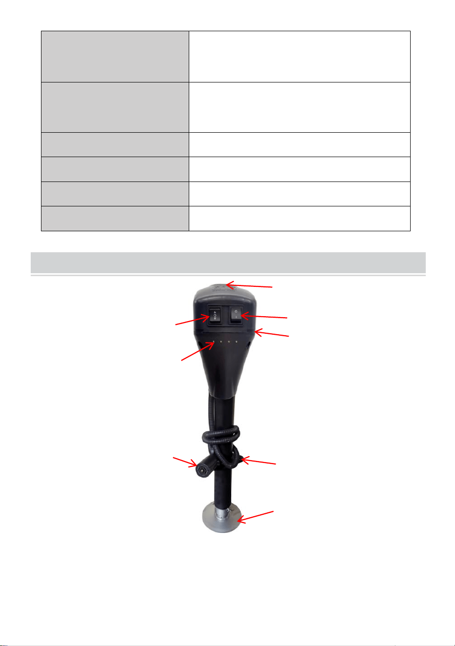
- 4 -
Avståndet mellan de två
hålen i D rop L t.ex
1,85 "
Höjd på monteringsstöd
från G runda ( 1 - hål)
10 " (lägst) / 28,3 " (högst)
Lyfttid
1 80 ±2 s (på belastning)
Ytter-/Innerrör Dia.
2-1/4" (svart) / 2" (zink)
Fotstorlek
5,5" (rund)
Minsta produkthöjd
29" (Total produkthöjd)
STRUCTURE DIAGRAM
1. Upp & Ner-brytare
2. Gummilock över manuell
vevåtkomst
3.Ljusbrytare
4. Plastkåpa
5. LED-ljus
6,7-vägs kontakt
7. Monteringsplatta
5
1
2
3
4
6
7
8
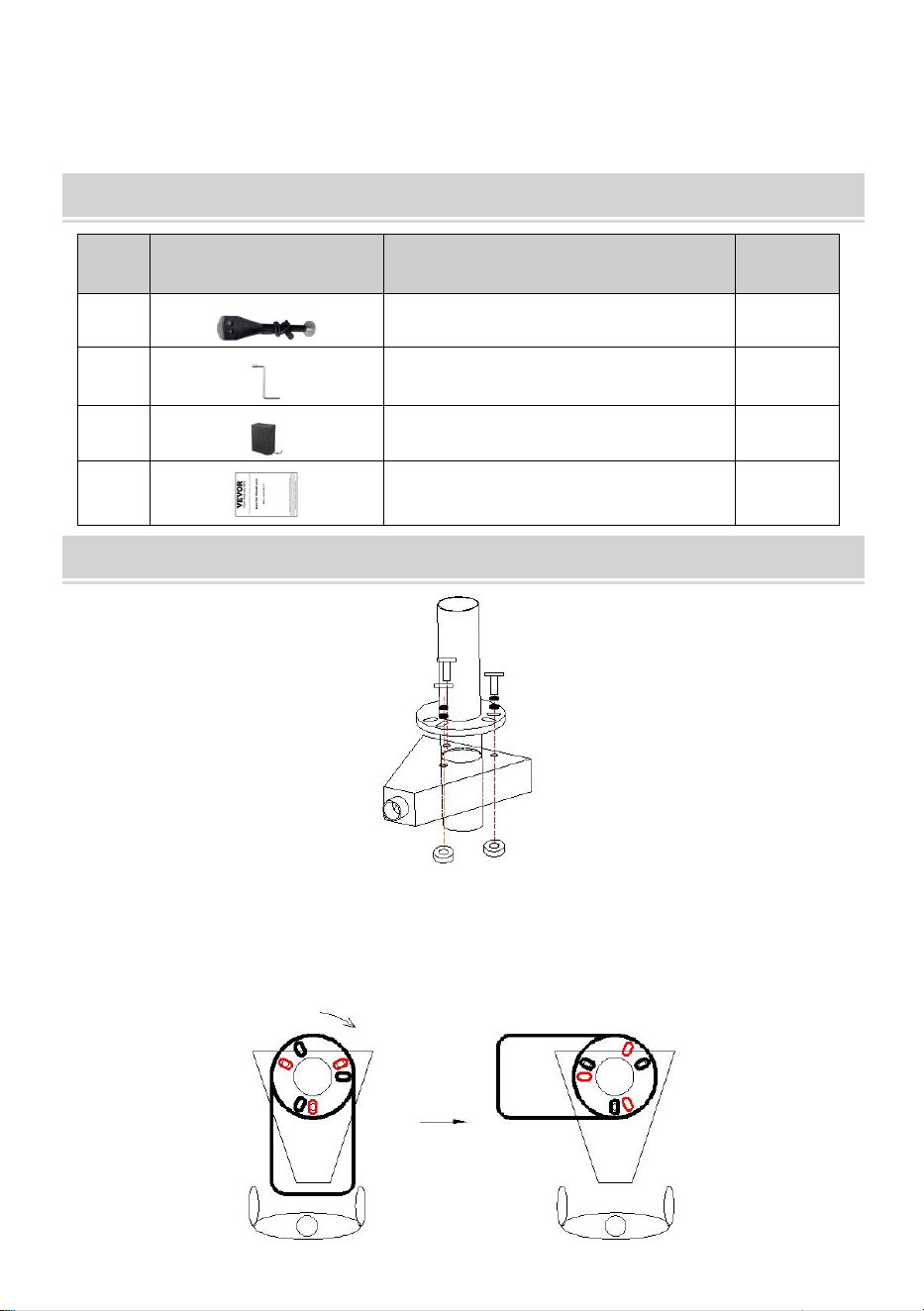
- 2 -
8.Förlängningstrampdyna
COMPONENTS
Inga
.
Bild
Namn
Antal
1
Elektrisk trailerjack
1
2
Manuellt vev
1
3
Vattentät S unshade B ag
1
4
Användarmanual
1
ASSEMBLY
36. När du monterar en släpvagnsdomkraft är det bäst att koppla den till
dragfordonet för att säkerställa att släpvagnen är säker.
37. Montera domkraft baserat på ritningen som visas ovan .
Motororienteringen kan väljas enligt nedan .
overlooking
Rotate 90 (Clockwise)
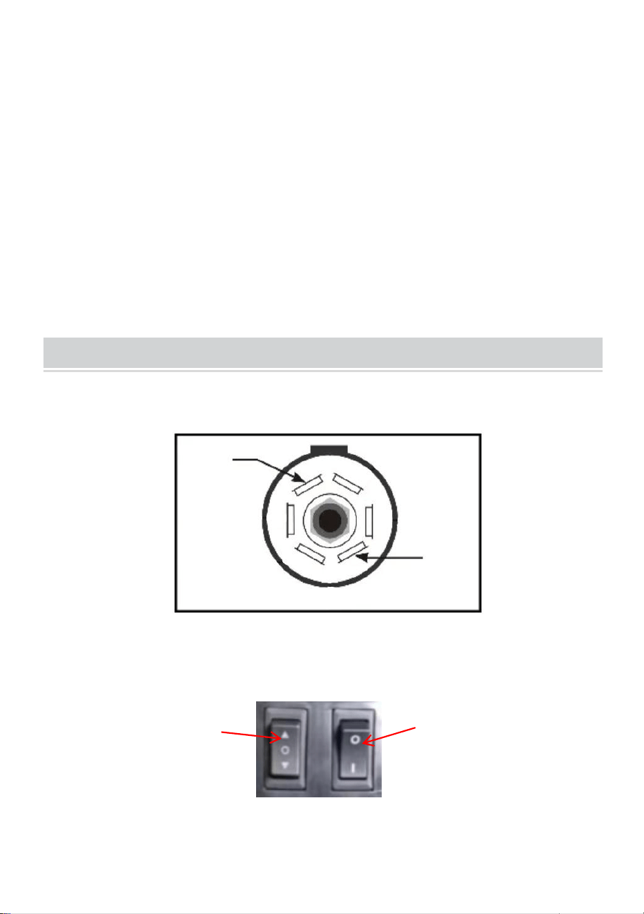
- 3 -
Obs: Välj monteringshål efter behov.(Figur ovan)
38. Skjut A-frame-jacket genom hålet ovanpå A-frame-kopplingen.
39. Passa in de tre slitsade hålen på domkraftens monteringsplatta mot
de tre hålen i kopplingen.
40. Med tre bultar och muttrar (måste köpas av användaren . ) fäst
domkraften ordentligt på toppen av a-ramkopplingen. (Kontrollera
regelbundet för att säkerställa att bultar/muttrar är ordentligt
åtdragna.)
OPERATION
15. Ingångsspänningen för denna produkt är DC12V, och den 7-stjärniga
kontakten är positiv/jord enligt bilden nedan.
Varning: Var noga med att notera att jordkabeln motsvarar jordkabeln på
bilens 7-stjärniga kontakt! Om inte, justera kablaget själv!
16. Inching för att testa ljusströmbrytare och upp- och nedströmbrytare.
3. Montera fotplattan efter att ha lyft den till lämplig höjd.
GND
VCC +
Lift Switch
Light Switch
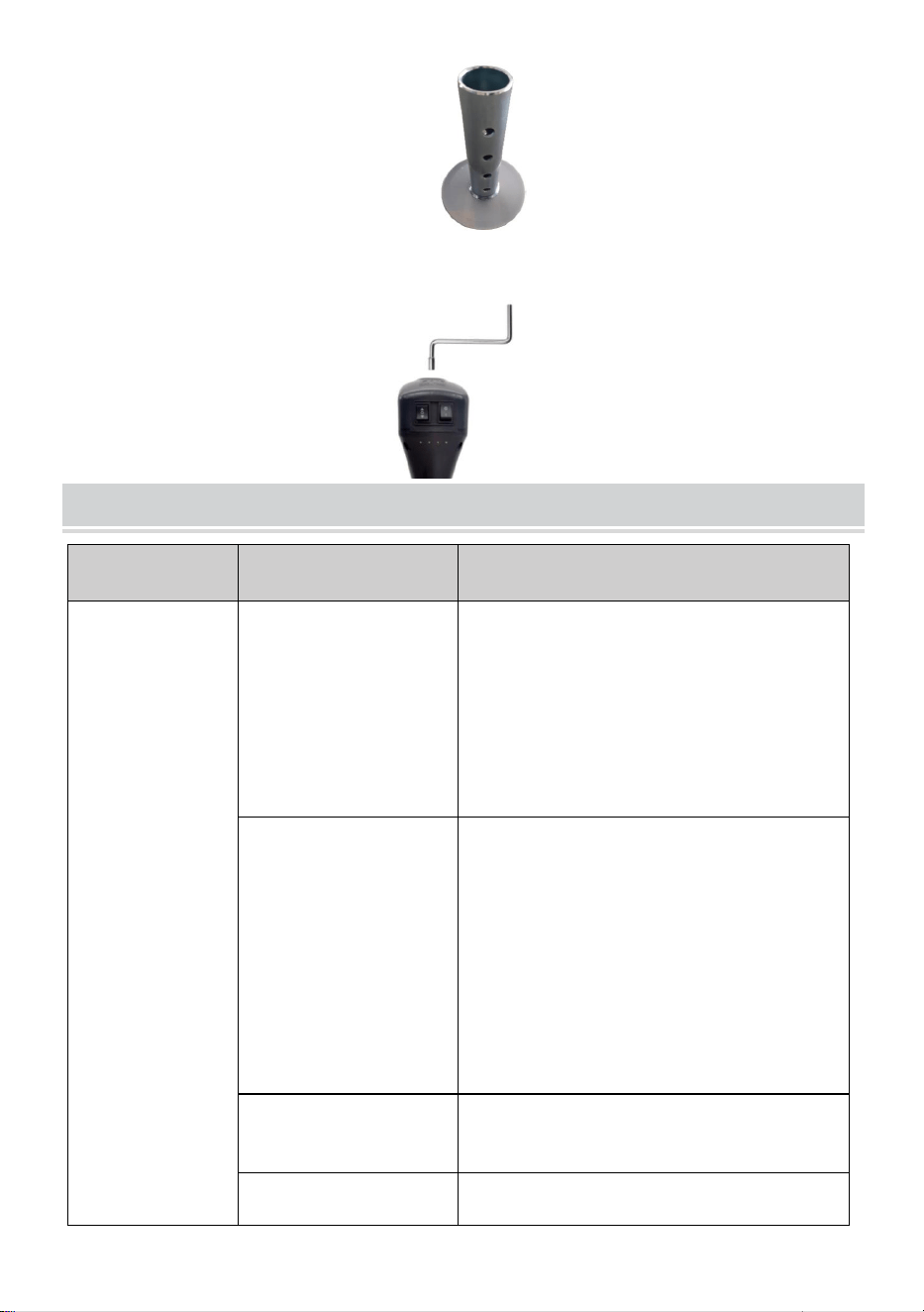
- 4 -
4.Sänk fotplattan på ett hårt golv/underlägg.
5. Om det behövs, ta bort gummiskyddet och dra upp den torra
kattöverdelen manuellt.
TROUBLESHOOTING
Fel
Möjlig orsak
Korrigerande åtgärd
Motorn
fungerar inte .
Ingen eller låg
spänning.
Kontrollera batteri och elektriska
anslutningar. Måste ha minst 10 VDC.
Om batteriet är lågt, anslut
släpvagnskabeln till dragfordonet och
starta dragfordonet för att ge ström till
domkraften.
Dålig jordning.
Rengör området mellan domkraftens
monteringsplatta och kopplingen och
se till att det är målat har tagits bort av
stjärnbrickorna .
Direkt metall-till-metall kontakt
måste finnas mellan
monteringskomponenterna för att
säkerställa god el
kontakta.
Lösa ledningar på
ON/OFF-brytaren.
Säkra trådanslutningar.
ON/OFF-brytaren
Byt strömbrytare.

- 5 -
Defekt motor.
Byt ut motorn.
Ljus fungerar
inte .
Lösa ledningar på
ON/OFF-brytare.
Säker trådanslutning.
Dålig glödlampa.
Byt glödlampa.
MAINTENANCE
36. Enstaka rengöring med mild tvål och vatten tillsammans med lätt
oljesmörjning av pivotpunkter förlänger toppprestanda och utseende.
37. Kontrollera med jämna mellanrum om skruvarna är lösa.
38. Inspektera domkraftsrören före varje användning och byt ut dem om
de är böjda eller skadade.
39. Om kablarna är anslutna till batteripolen, inspektera minst två gånger
om året för korrosion. Rengör med en lösning av bakpulver och vatten
och applicera sedan ett tunt lager fett.
40. Underhåll produkten genom att anta ett program för noggrann
reparation och underhåll i enlighet med följande rekommenderade
procedurer. Det rekommenderas att det allmänna tillståndet för ett
verktyg undersöks innan det används. Håll ditt verktyg i gott skick.
Håll handtagen torra, rena och fria från olja och fett. Följande diagram
är baserat på ett normalt driftschema.

- 6 -
Underhållsintervall
Underhållspunkt
Dagligen före operation
1. Den drivna A-frame domkraftsmotorn är förseglad
och underhållsfritt .
2. Inspektera domkraftsrören före varje användning
och byt ut dem om de är böjda eller skadade.
3. Se till att alla anslutningar är täta och fria från
korrosion och att uttaget är ordentligt jordat med
kopplingen (metall - till - metallkontakt).
4. Tvätta vid behov med mild tvål och vatten och skölj
noggrant. Motorns jordskruv och monteringsbultar
måste också vara rengjorda i fa jord
kontinuitetsproblem uppstår.
Efter de första 20
drifttimmarna
Dra ut domkraften helt och rengör det inre
domkraftsröret.
Efter de första 50
drifttimmarna eller varje
vecka
Dra ut domkraften helt och rengör det inre
domkraftsröret.
Varje år
Dra ut domkraften helt och rengör det inre
domkraftsröret en gång per år. Efter rengöring,
bestryk tuben med ett lätt fett eller
silikonspraysmörjmedel.