1
OPERATION MANUAL AND
INSTALLATION INSTRUCTIONS
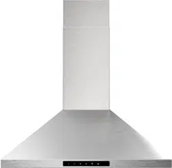
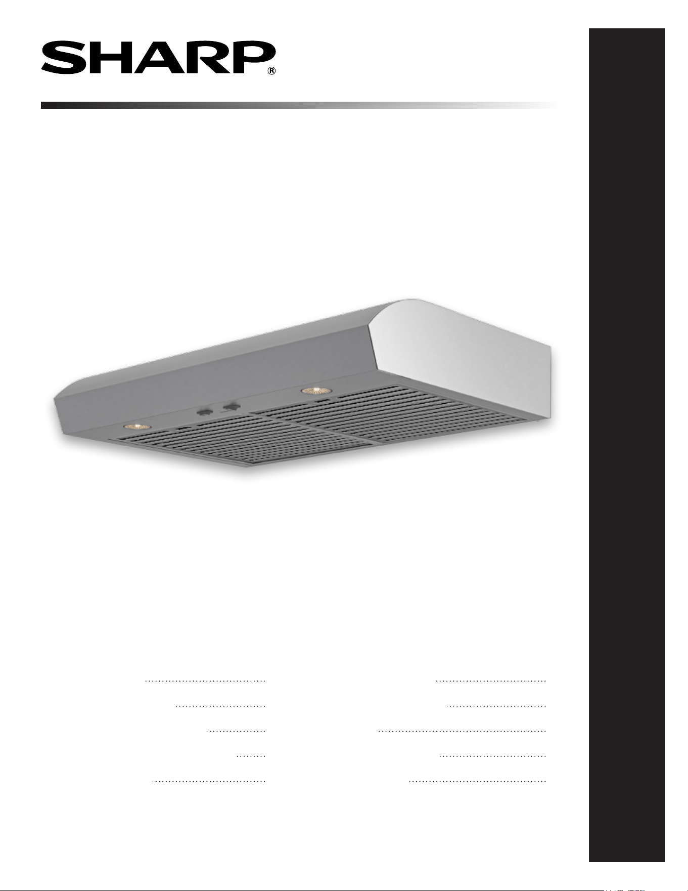
UNDER CABINET RANGE HOOD
MODEL: SHN3033MS
V
Under Cabinet Range Hood: Model SHN3033MS
CUSTOMER ASSISTANCE
CONSUMER LIMITED WARRANTY
BEFORE INSTALLING THE RANGE HOOD
APPEARANCE AND RANGE HOOD DIMENSIONS
RANGE HOOD MAIN PARTS
PRODUCT SPECIFICATIONS
INSTALLATION INSTRUCTIONS
OPERATIONS
CLEANING & MAINTENANCE
TROUBLE SHOOTING
2
3
4
5
6
7
8-13
14
15
16
2
CUSTOMER ASSISTANCE UNITED STATES ONLY
REGISTER YOUR PRODUCT
Registering your new product is easy and offers benets that help you get the most
out of your Sharp product including:
9 Convenience: If you ever need warranty support, your product information is already on le.
9 Communication:Stay up to date with important notications and special offers from SHARP.
9 Support: Quickly access support content including Owner’s Manuals, FAQ’s,
How-to Videos, and much more.
3 EASY WAYS TO REGISTER TODAY!
PRODUCT SUPPORT
If you have questions about the setup or operation of your product, please refer to
the corresponding section within this manual.
Additionally, visit www.sharpusa.com/support to access exclusive content about your
product including:
Æ FAQ’s and How-To Videos
Æ Find or Request Service
Æ Extended Warranty Options
Æ Downloads including the Installation Guide, Spec Sheet, and Owner’s Manual
CONTACT US
If at any time you have questions or comments concerning your SHARP product,
please contact the SHARP Customer Assistance Center. We are available to
assist you through multiple contact methods for your convenience:
Scan this QR Code on your mobile device Visit http://www.sharpusa.com/register
ONLINE
Visit our sites to
learn more about
your product at
sharpusa.com and
sbl.sharpusa.com
See the Contact Us section on our sites U.S. | www.sharpusa.com/support Contact a Sharp Advisor on the phone
Contact a Sharp Advisor on the phone
CALL US
US 800-BE-SHARP
800-237-4277
Mon-Fri: 7am-7pm CST
Sat-Sun: 9am-7pm CST
CALL US
US 800-BE-SHARP
800-237-4277
Mon-Fri: 7am-7pm CST
Sat-Sun: 9am-7pm CST
EMAIL
Available 24/7
US: sharpusa.com
CHAT ONLINE
Mon-Fri: 7am-7pm CST
Sat-Sun: 9am-7pm CST
SCAN
Use the camera or
QR code scanning
application on your
mobile device
TGANEB010MRR1 Aug 26, 2024
3
ENGISH
CONSUMER LIMITED WARRANTY
CONSUMER LIMITED WARRANTY FOR U.S. USERS
SHARP ELECTRONICS CORPORATION warrants to the first consumer purchaser that this Sharp brand
materials, and agrees that it will, at its option, either repair the defect or replace the defective Product or
part thereof with a new or remanufactured equivalent at no charge to the purchaser for parts or labor for the
forth below nor to any Product the exterior of which has been damaged or defaced, which has been subjected
to improper voltage or other misuse, abnormal service or handling, or which has been altered or modified in
design or construction.
In order to enforce the rights under this limited warranty, the purchaser should follow the steps set forth below
and provide proof of purchase to the servicer.
The limited warranty described herein is in addition to whatever implied warranties may be granted to
purchasers by law. ALL
IMPLIED WARRANTIES INCLUDING THE WARRANTIES OF MERCHANTABILITY
FORTH BELOW. Some
states do not allow limitations on how long an implied warranty lasts, so the above limitation may not apply to
you.
Neither the sales personnel of the seller nor any other person is authorized to make any warranties other than
those described herein, or to extend the duration of any warranties beyond the time period described herein
on behalf of Sharp.
The warranties described herein shall be the sole and exclusive warranties granted by Sharp and shall be
the sole and exclusive remedy available to the purchaser. Correction of defects, in the manner and for the
period of time described herein, shall constitute complete fulfillment of all liabilities and responsibilities of
Sharp to the purchaser with respect to the Product, and shall constitute full satisfaction of all claims, whether
based on contract, negligence, strict liability or otherwise. In no event shall Sharp be liable, or in any way
responsible, for any damages or defects in the Product which were caused by repairs or attempted repairs
performed by anyone other than an authorized servicer. Nor shall Sharp be liable or in any way responsible
for any incidental or consequential economic or property damage. Some states do not allow the exclusion of
incidental or consequential damages, so the above exclusion may not apply to you.
IN A
,
THE DISTRICT OF
COLUMBIA AND PUERTO RICO.
Your Product Model Number & Description:
Warranty Period for this Product:
Additional Item(s) Excluded From Warranty
Coverage:
Where to Obtain Service:
What to Do to Obtain Service:
available when you need
service for your Product.
any printed materials. Product which has been
commercial purposes
From a Sharp Authorized Servicer located in the United
T
Servicer, call Sharp Toll Free at 1-800-BE-
SHARP.
Be sure to have Proof of Purchase
available
TO OBTAIN SERVICE, SUPPLY, ACCESSORY OR PRODUCT INFORMATION, CALL 1-800-BE-SHARP,
OR VISIT OUR WEBSITE AT www.sharpusa.com
SAVE THE PROOF OF PURCHASE AS IT IS NEEDED SHOULD YOUR UNDER THE CABINET RANGE
HOOD EVER REQUIRE WARRANTY SERVICE.
SHARP ELECTRONICS CORPORATION
100 Paragon Drive, Montvale, NJ 07645, U.S.A.
FX-J80U_3rd_EN.indd 3 2021/09/29 11:39:10

4
BEFORE INSTALLING THE RANGE HOOD
READ AND SAVE THESE INSTRUCTIONS TO REDUCE THE RISK
OF FIRE, ELECTRIC SHOCK, OR INJURY TO
PERSON(S) OBSERVE THE FOLLOWING:
1 Use this unit only in the manner intended by the manufacturer. If
you have questions, contact the manufacturer at the address
or telephone number listed in the warranty.
2 Before servicing or cleaning unit, switch power off at service
panel and lock service disconnecting means to prevent power
from being switch on accidentally. When the service
disconnecting means cannot be locked, securely fasten a
prominent warning device, such as a tag, to the service panel.
3 Installation work and electrical wiring must be done by qualied
personnel in accordance with all applicable codes and standards,
including re-rated construction codes and standards.
4 Sufcient air is needed for proper combustion and exhausting of
gases through the duct of fuel burning equipment to prevent
backdrafting. Follow the heating equipment manufacturer’s
guidelines and safety standards such as those published by the
National Fire Protection Association (NFPA), the American
Society for Heating, Refrigeration and Air Conditioning
Engineers (ASHRAE) and the local
code authorities.
5 This product may have sharp edges. Be careful to avoid cuts and
abrasions during installation or cleaning.
6 When cutting or drilling into wall or ceiling, do not damage
electrical wiring and other hidden utilities.
7 Ducted fans must always be vented to the outdoors.
8 Do not use this unit with any other solid-state speed
control device.
9 Use only metal ductwork.
10 This unit must be grounded.
INSTALzLER: LEAVE THIS GUIDE WITH THE
HOMEOWNER.
HOMEOWNER: OPERATION AND MAINTENANCE
INFORMATION ARE ON PAGES 14-15.
WARNING Cancer and Reproductive Harm -
www.P65Warnings.ca.gov
TO REDUCE THE RISK OF A RANGE TOP GREASE FIRE:
1 Never leave surface units unattended at high settings. Boilovers
cause smoking and greasy spillovers that may ignite. Heat oils
slowly on low or medium settings.
2 Always turn hood ON when cooking at high heat or when
cooking aming foods (i.e. Crêpes Suzette, Cherries Jubilee,
Peppercorn Beef Flambé).
3 Clean ventilating fans frequently. Grease should not be allowed
to accumulate on fan or lters.
4 Use proper pan size. Always use cookware appropriate for the
size of the surface element.
WARNING TO REDUCE THE RISK OF INJURY TO
PERSON(S) IN THE EVENT OF A RANGE TOP GREASE FIRE,
OBSERVE THE FOLLOWING*:
1 SMOTHER FLAMES with a close-tting lid, cookie sheet, or
metal tray, then turn off the burner. BE CAREFUL TO
PREVENT BURNS. IF THE FLAMES DO NOT GO OUT
IMMEDIATELY, EVACUATE AND CALL THE
FIRE DEPARTMENT.
2 NEVER PICK UP A FLAMING PAN – You may be burned.
3 DO NOT USE WATER, including wet dishcloths or towels –
This could cause a violent steam explosion.
4 Use an extinguisher ONLY if:
A You know you have a Class ABC extinguisher and you
know how to operate it.
B The re is small and contained in the area where it started.
C The re department has been called.
D You can ght the re with your back to an exit.
*Based on “Kitchen Fire Safety Tips” published by NFPA.
CAUTION
1 For indoor use only.
2 For general ventilating use only. Do not use to exhaust
hazardous or explosive materials and vapors.
3 To avoid motor bearing damage and noisy and/or unbalanced
impeller, keep drywall spray, construction dust, etc. off
power unit.
4 Your hood motor has a thermal overload which will
automatically shut off the motor if it becomes overheated. The
motor will restart when it cools down. If the motor continues
to shut off and restart, have the hood serviced.
5 For best capture of cooking fumes, the bottom of the hood
MUST NOT BE LESS than 18” for electric range or 26” for
gas range and at a recommended maximum of 30” above the
cooking surface.
6 Two installers are recommended because of the size of this
hood.
7 To reduce risk of re and to properly exhaust air, be sure to
duct air outside. Do not exhaust air into spaces within walls or
ceilings or into attics, crawl spaces, or garages.
8
Be careful when installing the duct and hood, they may have
sharp edges.
9 Please read specication label on product for further
information and requirements.
5
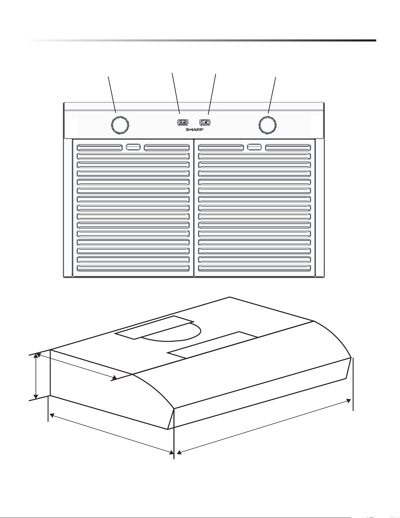
APPEARANCE AND RANGE HOOD DIMENSIONS
( inches )
2
9-
1
5/
1
6
”
2
0-1
/1
6
”
1
4
-
3/
1
6
”
5-1/8”
LED Light
Blower Switch
Light On/Off
LED Light
6
RANGE HOOD MAIN PARTS
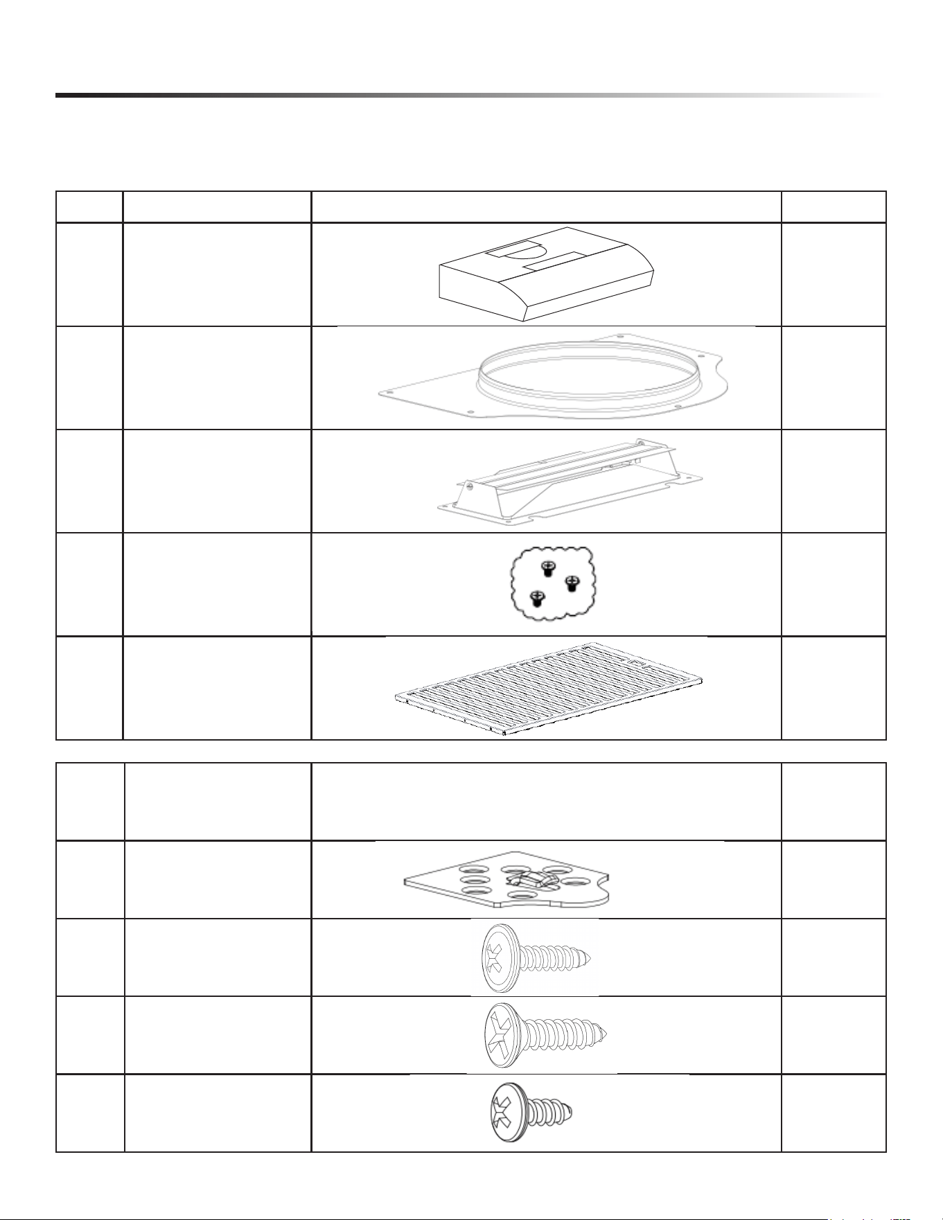
CONTENTS
Before proceeding to the installation, check the contents of the box. If items are missing or damaged, contact SHARP Customer Service at
1-800-BE-SHARP. Make sure that the following items are included:
NO. ITEM PICTURE QTY
1 HOOD
1
2 7” ROUND DUCT 1
3 3¼” X 10” DUCT 1
4 PARTS BAG
2
5 BAFFLE FILTER 2
NO.
PARTS BAG
CONTAINING
PICTURE QTY
1 Preformed Bracket
2
2
ST4 x 14 (3/16” x 9/16”)
Large at head self-tapping
6
3
ST4 x 16 (3/16” x 5/8”)
Countersunk self-tapping
4
4
ST 3/16” x 5/16” screw
Large at head self tapping
(burst nozzle)
5
7
ITEM SHN3033MS
Power Requirements
120 Volts, 0.8 Amps
60Hz
Case Dimensions —
Width 29-15/16”
Height 5-1/8”
Depth 20-1/16”
LED Lights 2 LED bulbs
Control Rocker Switch
Max. Blower CFM 350 CFM
Safety Standard ETL Listed
Net Weight 19.18 lbs
PRODUCT SPECIFICATIONS
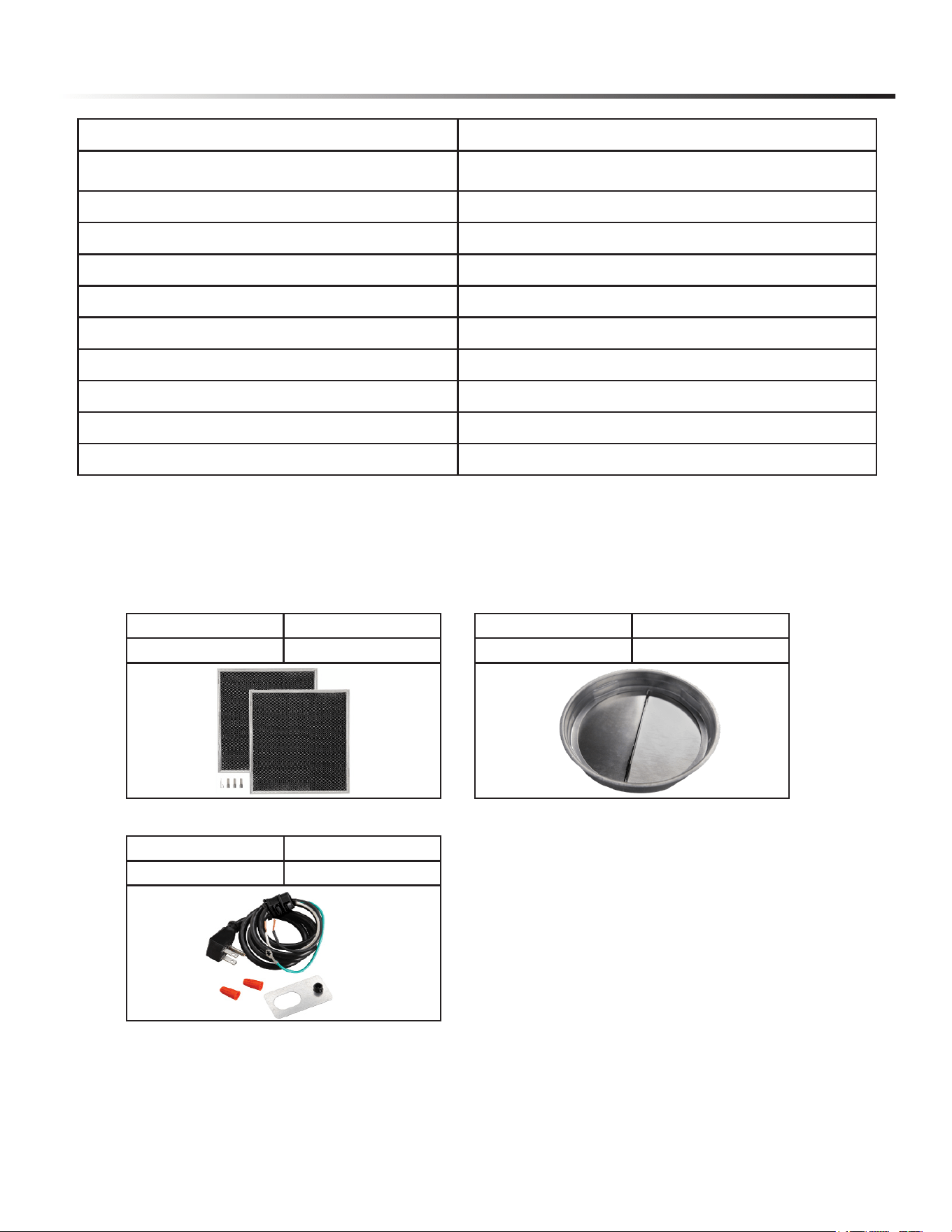
AVAILABLE ACCESSORY PARTS NUMBERS
PART NUMBER ITEM
SKRH30CFL Charcoal Filters
PART NUMBER ITEM
SKRH07DMP 7” Round Damper
PART NUMBER ITEM
SKRH36PWC AC Power Cord
8
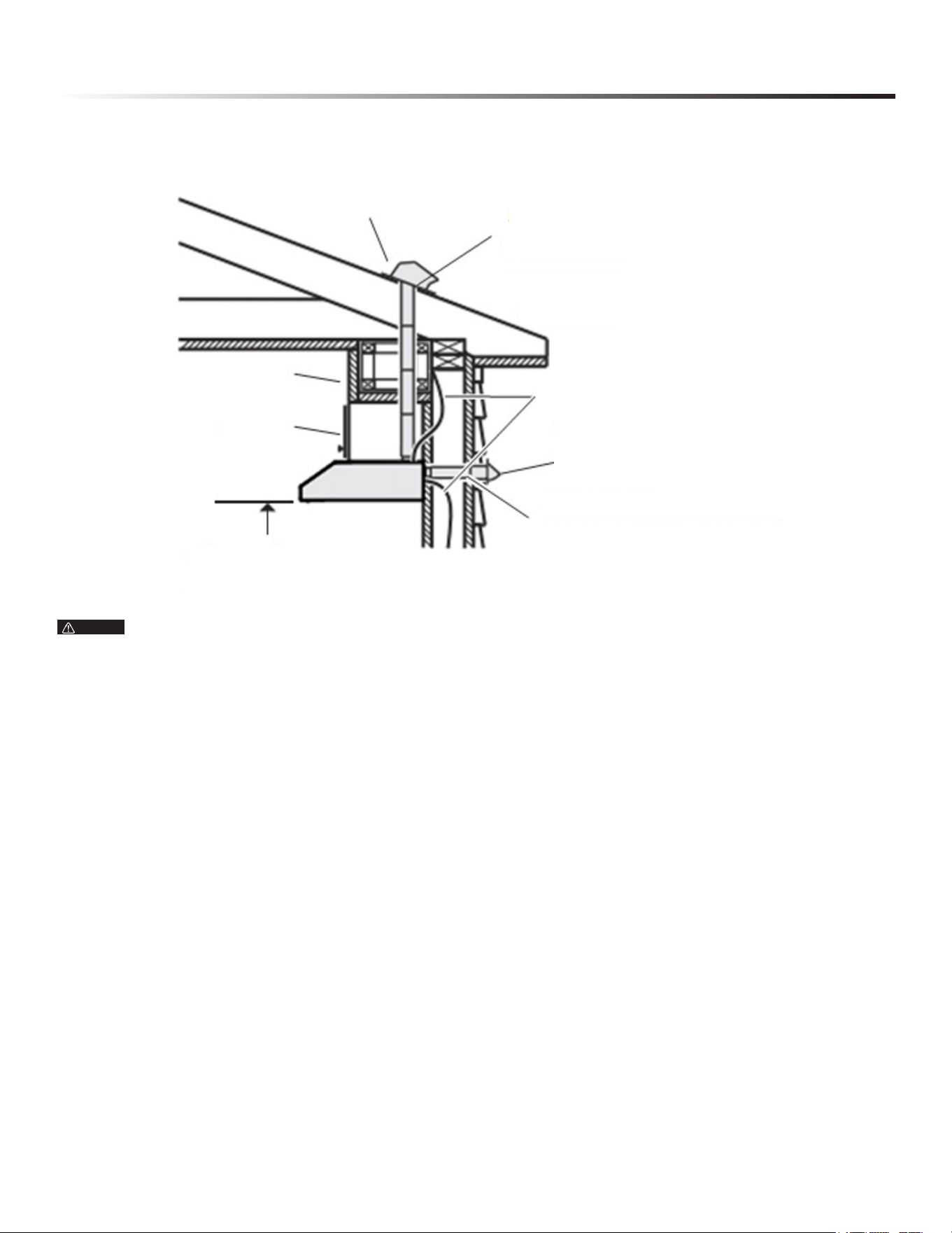
INSTALL DUCTWORK
(DUCTED INSTALLATIONS ONLY)
INSTALLATION INSTRUCTIONS
Distances over 30” are at the installer and user discretion.
1 Determine whether hood will discharge vertically (3¼” x 10” or
7” round), or horizontally (3¼” x 10” only).
2 Decide where the ductwork will run between the hood and
the outdoors.
3 Choose a straight, short duct run to allow the hood to perform
most efciently. Long duct runs, elbows and transitions will
reduce the performance of the hood. Use as few of them as
possible. When possible, use at least 2 foot straight runs before
any turns. Larger ductwork may be required for best
performance with longer duct runs.
4 Install wall cap or roof cap (sold separately); ensure there is no
leak in house insulation.
5 Connect metal ductwork to cap and work back towards the hood
location. Use 2” metal foil duct tape to seal the joints between
ductwork sections.
NOTE
18” MIN - 30” MAX
ABOVE ELECTRIC COOKTOP SURFACE
26” MIN - 30” MAX
ABOVE GAS COOKTOP SURFACE
SOFFIT
CABINET
HOOD
ROOFCAP
HOUSEWIRING
3¼” x 10” OR 7” ROUND DUCT
(FOR VERTICAL DISCHARGE)
(TOP PR BACK OF HOOD)
WALLCAP
3¼” x 10” DUCT
(FOR HORIZONTAL DISCHARGE)
9
INSTALLATION INSTRUCTIONS
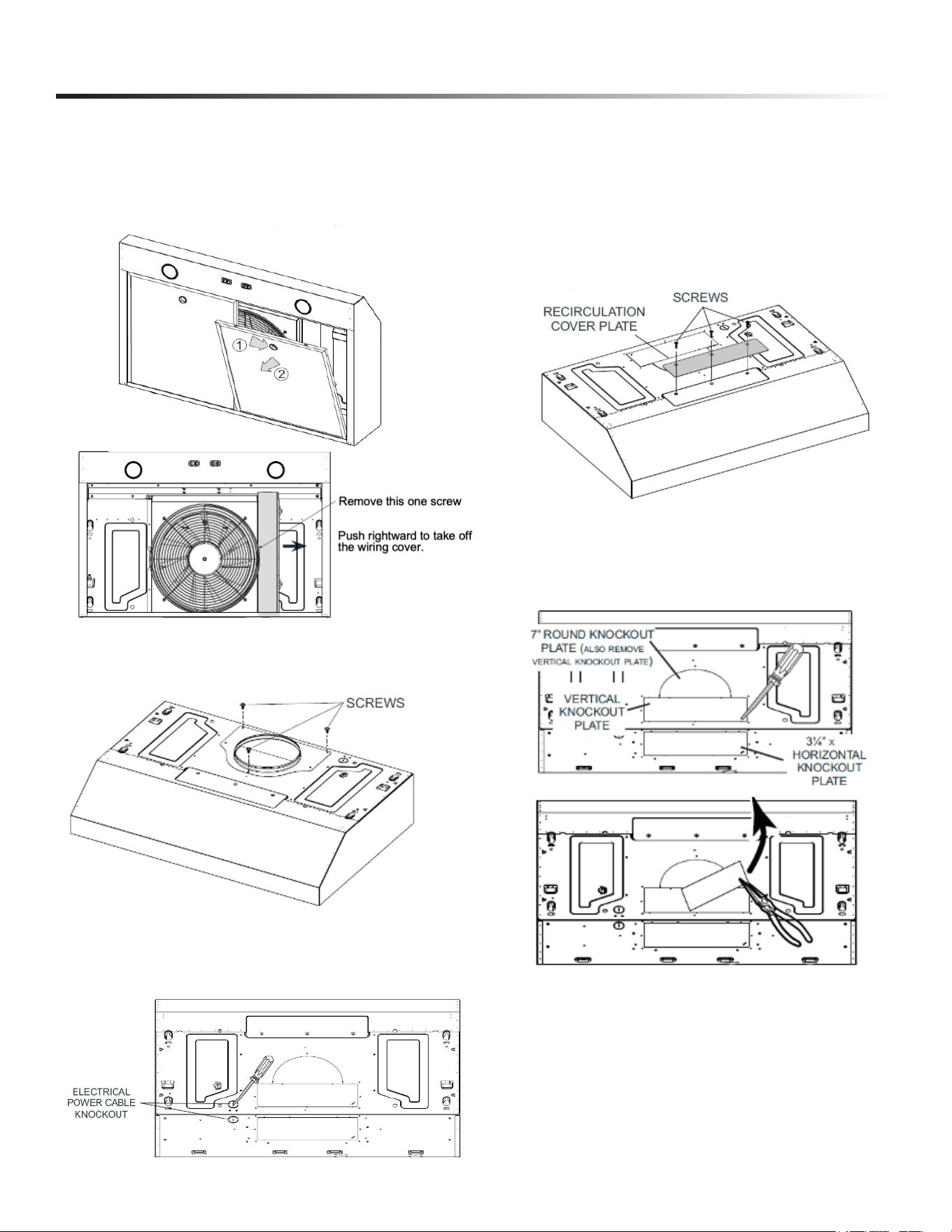
PREPARE THE HOOD
NOTE: If present, remove all protective polylm from the hood
and/or parts.
1 Remove the lters by pushing down 1 and tilting lters out 2.
2
3 Use Philips screwdriver to remove the 3 screws on the 7” round
duct. Take off the 7” round duct.
4 Remove Electrical Power Cable Knockout suitable for your
installation and install appropriate 1/2” strain relief
(not included).
REMOVE KNOCKOUT PLATES
There are three different preparations depending on your
installation method.
A. FOR RECIRCULATION INSTALLATION
B. FOR DUCTED INSTALLATION - ROUND DUCTING
Remove 3 screws retaining the recirculation cover plate to the
hood. This plate is not needed for recirculation. Discard or keep
for future use. Peel off and discard the membrane covering the
recirculation grille, ensuring the openings are totally cleared.
1 Remove the following knockout plates on the hood.
Horizontal knockout plate (3¼” x 10”) on the top AND
7-inch round knockout.
10
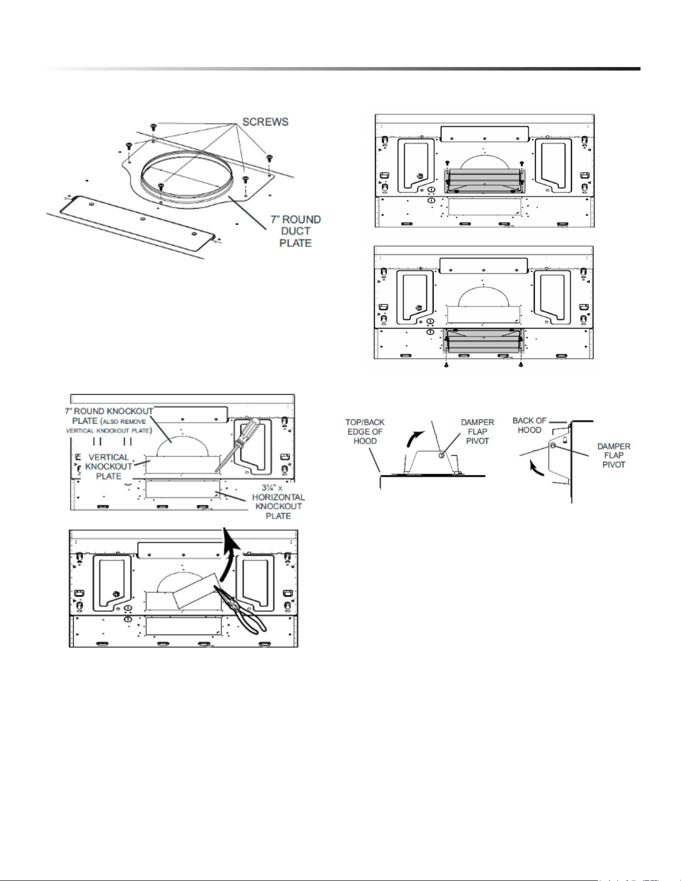
INSTALLATION INSTRUCTIONS
2 Attach 7” Round Duct Plate over the knockout opening with
3/16” x 5/16” screws.
TIP: Insert a small length of 7” round duct and seal the joint using
aluminum foil duct tape to ease connection with the house duct
work.
C. FOR DUCTED INSTALLATION - RECTANGULAR
DUCTING
1 Remove a knockout plate as appropriate for your installation
method. Horizontal knockout plate (3¼” x 10”) on the back
OR Vertical knockout plate (3¼” x 10”) on the top.
2 Attach a rectangular damper included (3¼” x 10”) over the
knockout opening with the 3/16” x 5/16” screws.
3 When installed, the 3¼” x 10” damper assembly must open as
shown below.
TIP: Insert a small length of duct over the 3¼” x 10” damper
assembly and seal the joint using aluminum foil duct tape to ease
connection with the house ductwork.
11
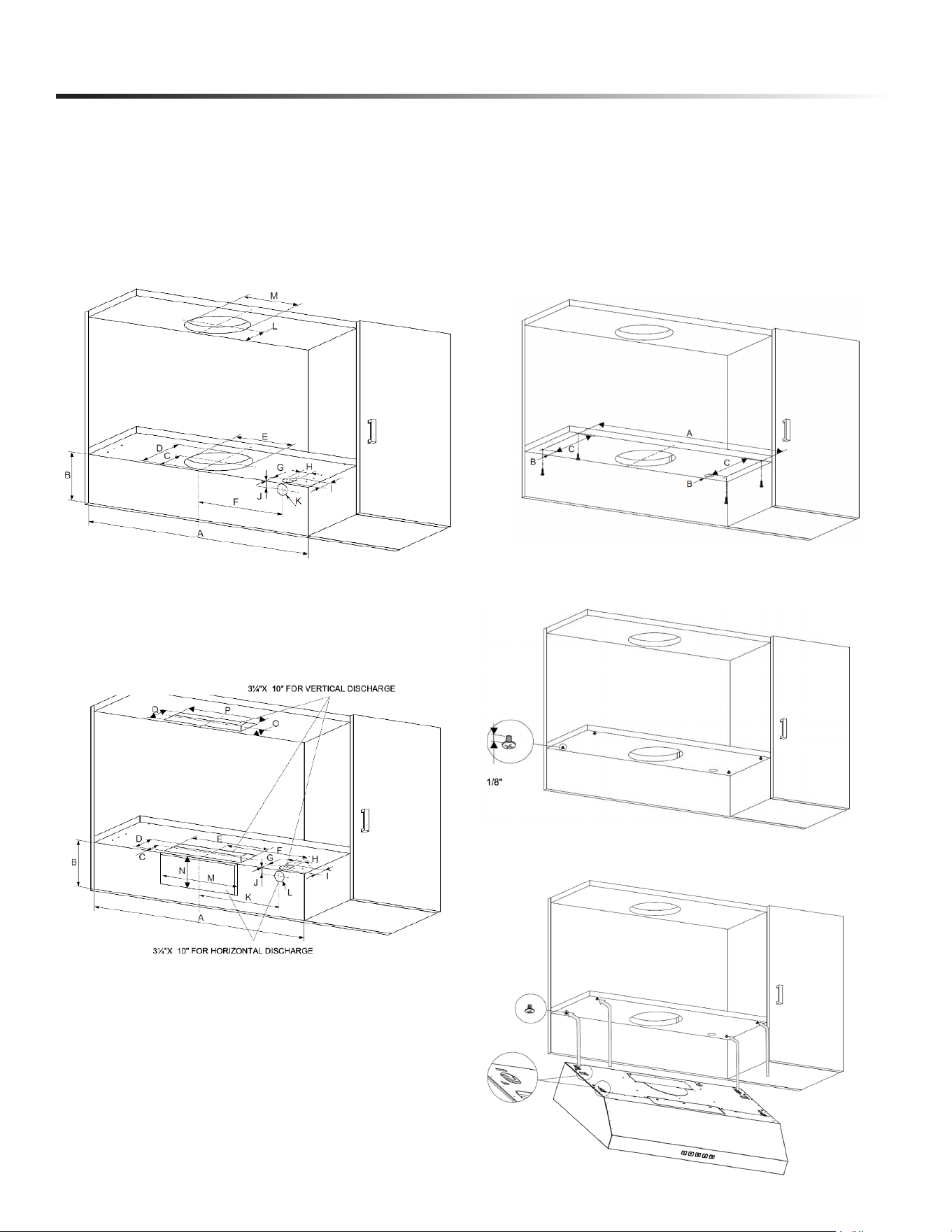
INSTALLATION INSTRUCTIONS
tapping) into the cabinet according to the positions on the
below drawing.
A=27 1/4” ; B=2 1/16” ; C=8
7/8”
NOTICE: Leave 1/8” between the screw head and the cabinet.
PREPARE THE HOOD LOCATION
This manual covers 2 kinds of installation: the standard (without
preformed brackets) and the preformed one-person installation
system (using included brackets).
Cut the ducting holes and the hole for the wire to go through inside
the cabinet, according to the ducting way you choose.
A. FOR 7” ROUND DUCT
A= 30 1/8” ; B= 5 1/8” ; C=4 7/8” ; D=8 7/16” ; E=φ 7 7/8” ; F=7
5/16” ; G=1 3/4” ; H=φ 1 3/8” ; I=2 3/16”; J=13/16”; K=φ1 3/8”;
L=4 9/16”; M=φ 7 7/8”
B. FOR
3¼” x 10” RECTANGULAR DUCT
A= 30 1/8” ; B= 5 1/8” ; C=2 15/16” ; D=4 3/4” ; E= 11” ; F=7
5/16” ; G=1 3/4” ; H=φ 1 3/8” ; I=φ 2 3/16” ; J=13/16” ; K=7
5/16” ; L=φ 1 3/8” ; M=11” ; N=4” ; O=2 15/16”; P=11” ; Q=4
3/4”
INSTALL THE HOOD
A. STANDARD INSTALLATION
(WITHOUT PREFORMED BRACKETS)
1 Run house power cable between service panel and
hood location.
2 Installing 4 pcs ST 3/16” x 9/16" screws (large flat head self
3 Lift the hood. Insert the 4 holes onto the screws. Slide the hood
in place.
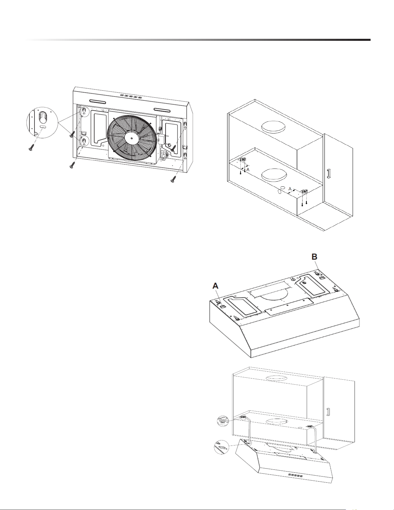
12
INSTALLATION INSTRUCTIONS
4 While holding the hood, run the house power cable into the
hood through the strain relief previously installed.
Use 2 pcs 3/16” x 9/16" screws (large flat head self tapping)
to fix the hood.
5
6
Then tighten the other 4 pcs ST 3/16” x 9/16" screws that
are installed as step 2.
7 (FOR DUCTED INSTALLATION ONLY)
Connect the ductwork to the hood and use metal foil duct
tape to make joints secure and air-tight. Make sure the
damper assembly (or round duct plate) enters the ductwork
and that the damper opens and closes freely.
B. INSTALLATION WITH PREFORMED BRACKETS
1 Run house power cable between service panel and
hood location.
2 Use 4 pcs ST 3/16: x
5/8” screws (countersunk self
tapping) to x the 2 pcs preformed brackets onto the cabinet.
A=3 1/2”
3 Lift the hood. Insert the A B positions of the hood into the
preformed bracket.
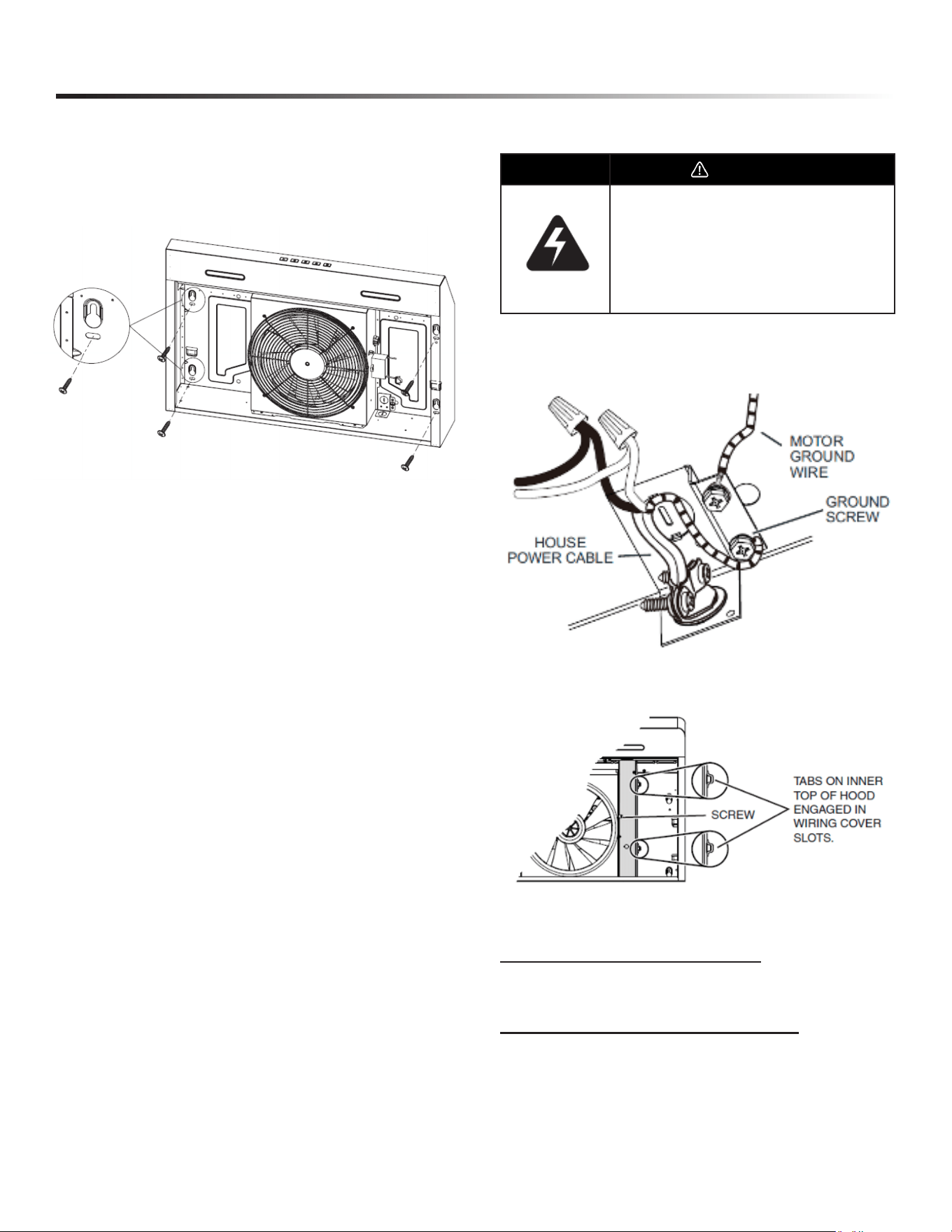
13
INSTALLATION INSTRUCTIONS
CONNECT THE WIRING
WARNING
Risk of electric shock. Electrical wiring must be done
by qualied personnel in accordance with all
applicable codes and standards. Before connecting
wires, switch power off at service panel and lock
service disconnecting means to prevent power from
being switched on accidentally.
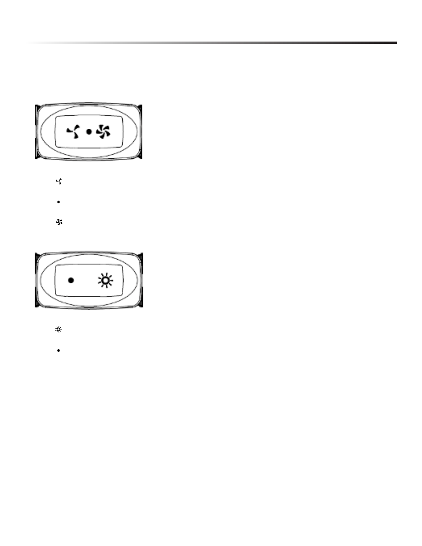
1 Connect House Power Cable to range hood wiring:
BLACK to BLACK, WHITE to WHITE and GREEN or
bare wire under GREEN ground screw.
2 Reinstall wiring cover and attach it to the hood using its
retaining screw.
INSTALL THE FILTERS
(FOR DUCTED INSTALLATION ONLY)
Re-install grease lters removed in step 1, under “Prepare the
Hood”.
(FOR NON-DUCTED INSTALLATION ONLY)
Purchase two non-ducted lters from your local retailer or call
1-800-BE-SHARP (see product specication label for lter type).
Attach the non-ducted lters following instructions packed with
the non-ducted lters.
4 TEMPORARILY hang the hood by the preformed brackets.
While holding the hood, run the house power cable into the
hood through the strain relief previously installed.
5 Fasten the hood by installing 4 pcs ST 3/16” x 9/16" screws
(large at head self tapping) into slots.
6 (FOR DUCTED INSTALLATION ONLY)
Connect the ductwork to the hood and use metal foil duct
tape to make joints secure and air-tight. Make sure the
damper assembly (or round duct plate) enters the ductwork
and that the damper opens and closes freely.
14
OPERATIONS
Always turn your hood on before you begin cooking to establish an air ow in the kitchen. Let the blower run for a few minutes to clear the
air after you turn off the range. This will help keep the whole kitchen cleaner and fresher.
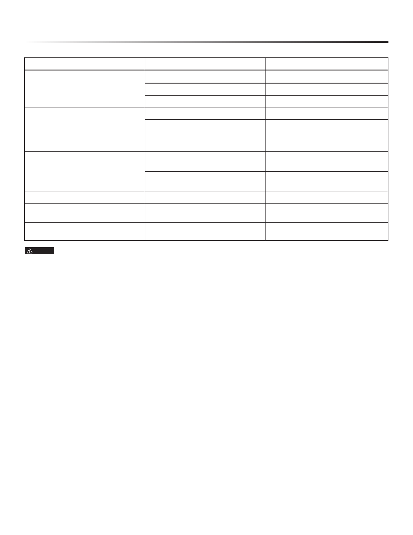
Operate the hood as follows:
A. BLOWER SWITCH
1. Press
2. Press
3. Press
to turn on blower at low speed.
to turn blower off.
to turn on blower at high speed.
1. Press
2. Press
to turn light on.
to turn light off.

15
CLEANING & MAINTENANCE
The motor is permanently lubricated and never needs oiling. If
the motor bearings make excessive or unusual noise, replace the
blower with the exact service blower.
MOTOR
Proper maintenance of the Range Hood will assure proper
performance of the unit.
The inlay control panel can be cleaned using warm soapy water.
Ensure the cloth is clean and well wrung before cleaning. Use a
dry soft cloth to remove any excess moisture left after cleaning.
CONTROL PANEL SURFACE
IMPORTANT
Use mild liquid dish detergents and avoid using harsh cleaning
chemicals, strong household detergents or products containing
abrasives, as this will affect the appearance of the appliance and
potentially remove any printing of artwork on the control panel
and may void manufactures warranty.
Remove grease lters by pulling down on the metal latch tab. This
will disengage the lter from the hood. Tilt the lter downward
and remove.
The grease lters should be cleaned frequently. Use a warm
dishwasher detergent solution. Grease lters are dishwasher safe.
Clean all-metal lters in the dishwasher using a non-phosphate
detergent. Discoloration of the lters may occur if using
phosphate detergents, or as a result of local water conditions - but
this will not affect lter performance. This discoloration is not
covered by the warranty. To minimize or prevent discoloration,
hand-wash lters using a mild detergent.
GREASE FILTERS
The non-ducted recirculation lters should be changed every 6
months. Replace more often if your cooking style generates extra
grease, such as frying and wok cooking. Turn the lter mounting
tabs to remove lter and replace.
NON-DUCTED RECIRCULATION FILTERS
STAINLESS STEEL CLEANING
DO:
• Regularly wash with clean cloth or rag soaked with warm
water and mild soap or liquid dish detergent.
• Always clean in the direction of original polish lines.
• Always rinse well with clear water (2 or 3 times) after
cleaning. Wipe dry completely.
• You may also use a specialized household stainless steel
cleaner.
DON’T:
• Use any steel or stainless steel wool or any other scrapers to
remove stubborn dirt.
• Use any harsh or abrasive cleaners.
• Allow dirt to accumulate.
• Let plaster dust or any other construction residues reach the
hood. During construction/renovation, cover the range hood
to make sure no dust sticks to the stainless steel surface.
AVOID: WHEN CHOOSING A DETERGENT
• Any cleaners that contain bleach will attack stainless steel.
• Any products containing: chloride, uoride, iodide, bromide
will deteriorate surfaces rapidly.
• Any combustible products used for cleaning such as
acetone, alcohol, ether, benzol, etc., are highly explosive
and should never be used close to a range.
Clean with warm water and mild detergent only. If discoloration
occurs, use a nish polish such as automotive polish. (DO NOT
use rough abrasive cleaner or porcelain cleaner.)
PAINTED FINISH CLEANING
16
TROUBLESHOOTING
FAULT POSSIBLE CAUSE SOLUTION
Light on, but motor does not work
• Fan switch turned off • Select a fan switch position
• Fan switch failed • Contact service center
• Motor failed • Contact service center
Light on, but motor does not work
• House fuse blown • Reset/Replace fuses
• Mains power cable is loose or
disconnected
• Ret mains power cable to power
outlet
• Switch power outlet on
Oil Leakage
• One way valve and the outlet are not
tightly sealed
• Take down the one way valve and seal
with sealant
• Oil buildup in the grease filters. • Clean up the grease filters
Lights not working
• Broken or faulty bulbs • Replace bulbs as per this instruction
Insufcient suction
• The distance between the range hood
and the gas top is too far
• Ret the range hood to the correct
distance
The Range hood inclines
• The xing screw is not tight enough • Tightening the hanging screw and
make it horizontal
NOTE
Any electrical repairs to this appliance must conform to your local, state and federal laws. Please contact the SHARP Customer Service
1-800-BE-SHARP if there are any questions before undertaking any of the above. Always disconnect the unit from the power source when
opening the unit.

17

18

19

20
SHARP ELECTRONICS CORPORATION • 100 Paragon Drive • Montvale, New Jersey 07645 • USA
800-BE-SHARP (800-237-4277)
August 11, 2026