1
SFG3075MS
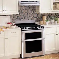
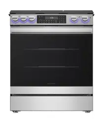
30" FREESTANDING GAS RANGE
INSTALLATION MANUAL
IMPORTANT NOTICE
• Read and save these instructions for future reference.
• Installation and service must be performed by a qualified installer.
• Save this installation manual for local electrical inspector's use.
WARNING
• If the information in this manual is not followed exactly, a re or
explosion may occur and cause property damage, personal injury
or death. In the event of a re or explosion, move away from the
appliance immediately and call the local re department.
• NEVER attempt to extinguish oil/grease re with water.
• Do not store or use gasoline or other ammable vapors and liquids
in the vicinity of this or any other appliance.
• Installation and ser vice must be perfor med by a qualied installer
and service provider or the gas supplier.
IF YOU SMELL GAS
• Do not try to light any appliance.
• Do not touch any electrical switch.
• Do not use any phone in the building.
• Immediately contact the local gas supplier from a neighbor's
phone and follow the instructions of the gas supplier.
• If the local gas supplier is unreachable, call the re department.
SAFELY LIFT AND MOVE UNIT
• Two people are required to safely lift and move this unit.
• Do not move unit by pushing or pulling on the door or control
panel. Do not lift by the cooktop edges or display panel. Push,
pull or lift only on the body or structural areas, such as oven,
oven face, or back corners of range.
• Move range by lifting, not sliding, to prevent damage to oors.
Use cardboard, plywood or stiff plastic to protect oors if sliding
is necessary.
UNPACKING THE APPLIANCE
•
WARNING
Before moving the unit, it is important to remove
grates in the lower drawer. Remove the tape, pull out the drawer,
and remove boxed grates.
• Remove all packing materials from inside the appliance. Remove
the feature sticker, if there is one, from the outside of the oven.
• Check the appliance for any damage. If there is any damage,
do not operate the appliance and contact your dealer or call
1-800-BE-SHARP.
• Record the model and serial number.
IMPORTANT NOTES TO THE INSTALLER
• Leave these instructions with the consumer after installation.
• Read the entire Installation Manual before installing the appliance.
• Remove all packing material before connecting the electrical
and gas supply.
• This appliance is shipped from the factory set for use with Natural
Gas. It can be conver ted for use with LP (propane). The conversion
must be performed by a qualied technician in accordance
with the installation instructions and local codes. The agency
performing this work assumes responsibility for the conversion.
• To convert the range for use with Propane, a qualied technician
must follow the included instructions with the LP Conversion kit.
INSTALLATION LOCATION
• The dimensions and clearances in this manual indicate minimum
clearance required.
• Minimum distance between rangetop and overhead cabinetry is 30".
• The contact surface and oor on which the appliance rests must
be solid and level.
• Ensure installation location has proper electrical supply.
• A manual valve is to be installed in an accessible, external location
for the purpose of turning on or off gas supply to the appliance.
• Any openings in the wall behind the appliance and in the oor
under the appliance must be sealed.
• DO NOT install this appliance with a ventilation system that
blows air downward toward the appliance. Use of a ventilation
system that blows air downward toward the appliance can cause
ignition and combustion problems with gas cooking appliances
and cause risk of personal injury or unintended operation.
1
2
OBSERVE GOVERNING CODES
• Observe all governing codes and ordinances.
• Installation must conform with local codes or, in the absence
of local codes, with the National Fuel Gas Code, ANSI
Z223.1/NFPA 54.
• This appliance requires connection to a 3-prong, 120VAC,
60Hz grounded electrical source. When installed, appliance
must be electrically grounded in accordance with local codes
or, in the absence of local codes, with the National Electrical
Code, NFPA 70.
GAS SUPPLY TESTING
• The appliance and its individual shut-off valve must be
disconnected from the gas supply piping system during any
pressure testing of that system at test pressures in excess of
1
/2
psi (3.5 kPa).
• The appliance must be isolated from the gas supply piping
system by closing its individual manual shut-off valve during any
pressure testing of the gas supply piping system at test pressures
equal to or less than
1
/2 psi (3.5 kPa).
• Leak testing of the appliance shall be conducted according to the
manufacturer's instructions.
IMPORTANT NOTES TO THE CONSUMER
Keep this Installation Manual with your Operation Manual for
future reference.
• When using any appliance generating heat, safety precautions
must be followed. See the Operation Manual for safety
precautions and follow them carefully.
• The unit must be installed and grounded properly by a qualied
installer or service technician.
• Some models of this unit come equipped for optional Wi-Fi
connection. In order to activate the Wi-Fi functionality, the area
in which the unit is installed requires a Wi-Fi signal. Please see
the Operation Manual for the minimum Wi-Fi requirements.
PARTS
Before installing, verify all parts are included. If any parts are damaged
and/or missing, contact your dealer or call 1-800-BE-SHARP.
PARTS INCLUDED
PARTS QUANTITY
Surface Burners and Caps 5
Surface Burner Grates 3
Anti-Tip Bracket 1 bracket, 2 screws
Flat Rack 2
LP Conversion Kit 1
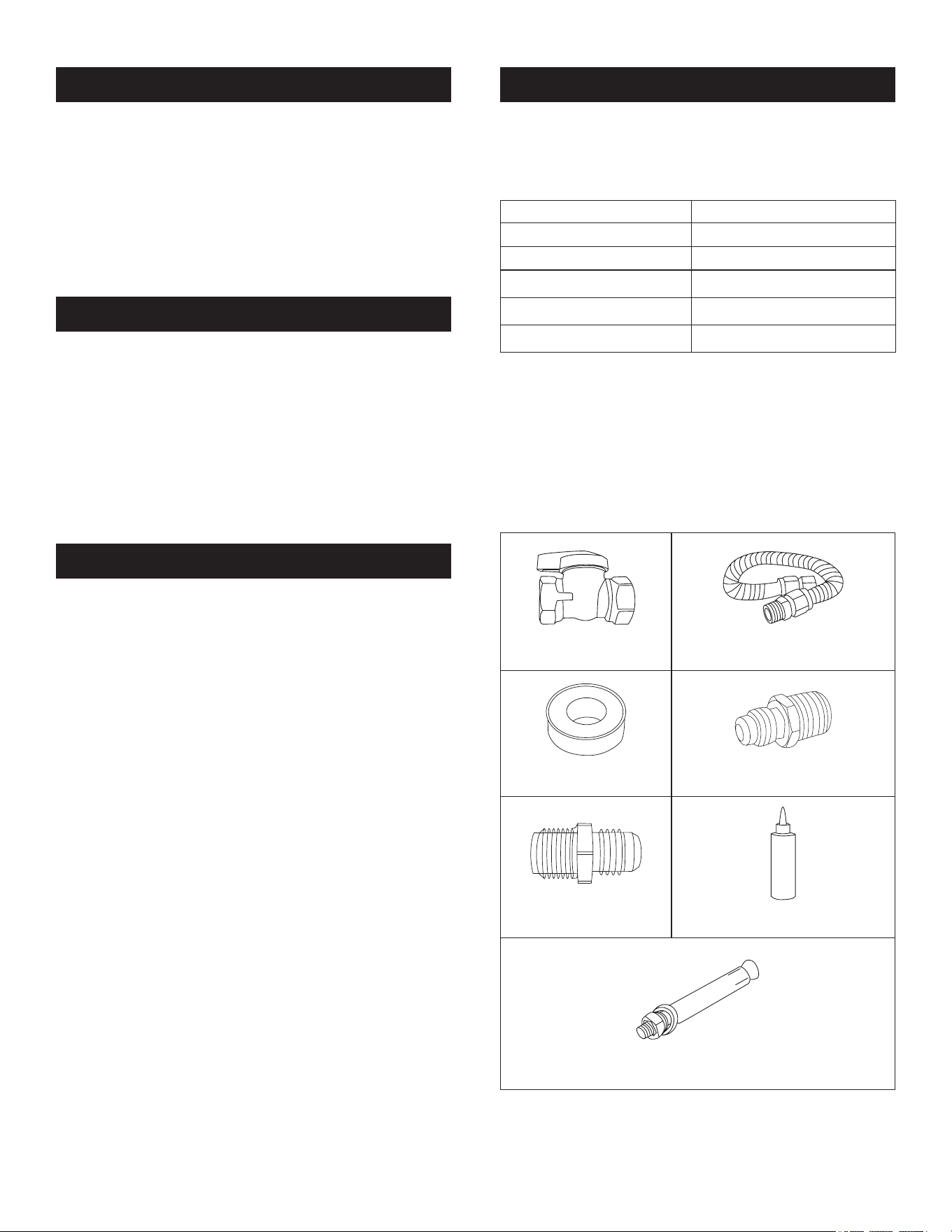
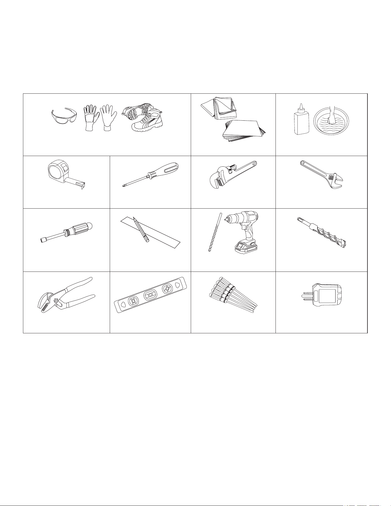
MATERIALS NEEDED
(NOT INCLUDED)
The gas utility connection and house structure at each home may be
different, so the specic parts required for connection to the house
are not included with the product and must be purchased separately.
The parts identied below are or may be required to complete the
installation. For gas supply connections, always use new supply line
and adapters, and never use an old part for new range connections.
GAS LINE
SH UT- OFF VALVE
NEW FLEXIBLE GAS SUPPLY LINE
3
/4" OR
1
/2" NPT X
1
/2" ID
GAS-APPROVED TEFLON TAPE
OR JOINT COMPOUND
NEW FLARE UNION ADAPTER
3
/4" OR
1
/2" NPT X
1
/2" ID
NEW FLARE UNION ADAPTER
1
/2" NPT X
1
/2" ID
LIQUID LEAK DETECTOR OR SOAPY
WATER SOLUTION
5
/16" OD SLEEVE ANCHOR (WITH
1
/4" BOLT) - 2 PCS
(FOR CONCRETE FLOORS ONLY)
3
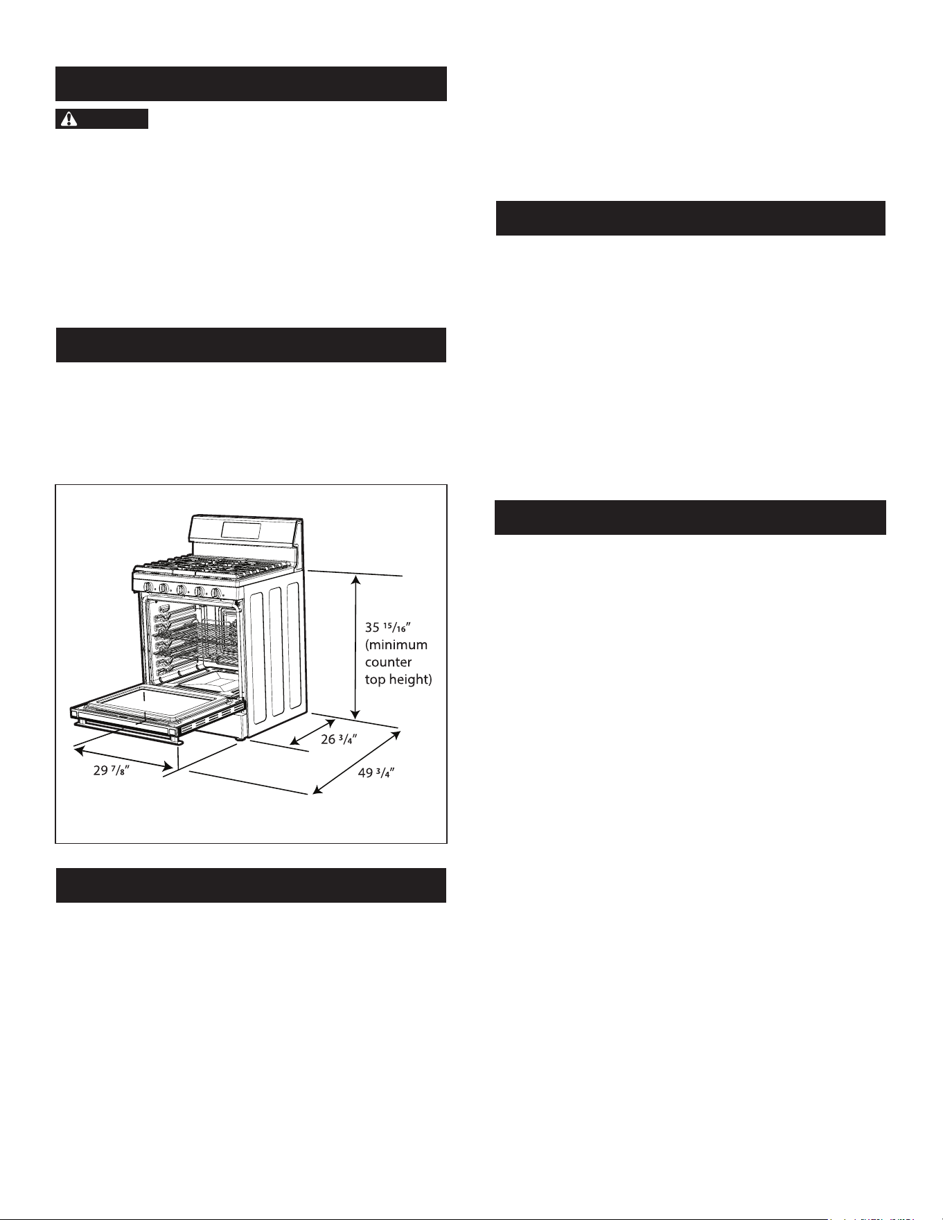
TOOLS NEEDED
CUT RESISTANT GLOVES, SAFETY GLASSES OR GOGGLES, STEEL-TOED SHOES
(FOR YOUR SAFETY AND PROTECTION)
DROP CLOTH OR CARDBOARD
(OPTIONAL - TO PROTECT FLOOR)
LIQUID LEAK DETECTOR OR SOAPY WATER
SOLUTION (FOR GAS LEAK TESTING)
TAPE ME ASURE
(TO CONFIRM INSTALLATION SPACE)
PHILLIPS SCREWDRIVER (TO ACCESS
SERVICEABLE COVERS)
PIPE WRENCH
(FOR GAS CONNECTIONS)
OPEN END OR ADJUSTABLE WRENCH (FOR
GAS CONNECTIONS AND
GAS CONVERSION)
NUT DRIVER
(FOR GAS CONVERSION AND
ANTI-TIP BRACKET INSTALLATION)
PENCIL AND RULER
(FOR ANTI-TIP BRACKET
INSTALL ATION)
DRILL AND
1
/8" DRILL BIT (FOR ANTI-TIP
BRACKET INSTALLATION)
MASONRY DRILL BIT
(FOR ANTI-TIP BRACKET INSTALLATION -
CONCRETE FLOORS ONLY)
ADJUSTABLE GROOVE-JOINT OR
GOOSENECK PLIERS
(FOR LEVELING PRODUCT)
LEVEL
(FOR LEVELING PRODUCT)
SMALL BLADE SCREWDRIVER (FOR
ADJUSTING SURFACE BURNER SIMMER
SETTING)
120VAC OUTLET TESTER (TO CHECK
ELECTRIC SUPPLY GROUNDING)
SUPPLIED BY INSTALLER
(NOT INCLUDED)
The utility connection and house structure of each home varies,
so specic tools required for connection are not included with the
product and must be supplied by the installer.
4
IMPORTANT SAFETY INSTRUCTIONS
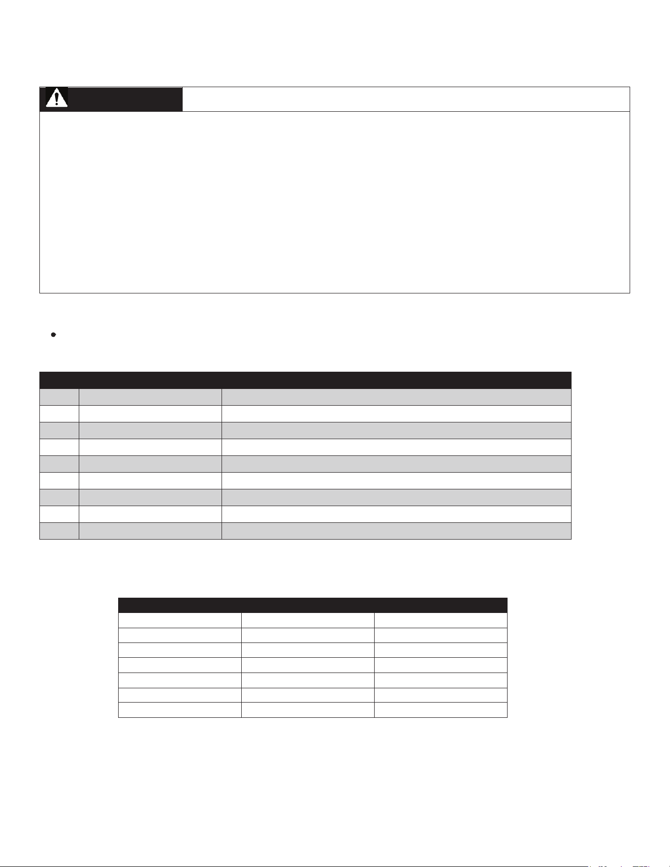
WARNING
If the information in this manual is not followed
exactly, a re or electrical shock may result which could cause
property damage, personal injury or death.
• To reduce the risk of tipping, the unit must be secured by a
properly installed Anti-Tip bracket.
• Ensure that airow is unobstructed at the front of the unit.
• This unit must be electrically grounded in accordance with
local codes.
• Wall coverings, countertops and cabinets around the unit must
be able to withstand heat generated by the unit.
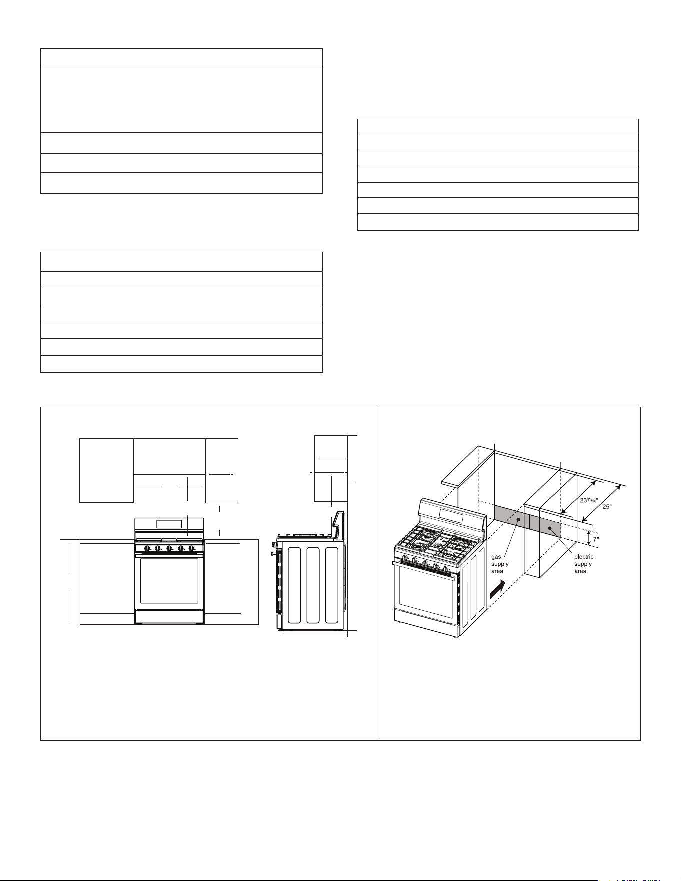
CLEARANCES AND DIMENSIONS
• The dimensions and clearances in this manual indicate minimum
clearance required.
• The contact surface of the installation must be solid and level.
• The surface on which the unit sits must be const r ucted of plywood
strong enough to support 250 lbs.
FIGURE 1
GAS SUPPLY REQUIREMENTS
This product is equipped with a gas pressure regulator that
operates at a pressure of 5" of water column for operation with
natural gas or 10" of water column when converted for operation
with LP (propane).
The Freestanding Gas Range is preset for use with Natural Gas
and can be converted for use with Propane (LP) with the supplied
LP conversion kit. When using this range on LP gas, conversion
must be made by a qualied LP installer before attempting to
operate the range.
For proper operation, the pressure of natural gas supplied to the
regulator must be between 5" and 13" of water column. For LP gas,
the pressure supplied to the regulator must be between 10" and 13" of
water column.
When checking for correct operation of the regulator, the inlet
pressure must be at least 1" more than the operating (manifold)
pressure as given above. The pressure regulator located at the inlet
of the range must remain in the supply line regardless of which type
of gas is being used. A exible metal appliance connector used to
connect the range to the gas supply line should have an I.D. of
5
/8"
and a maximum length of 5'.
ELECTRICAL SUPPLY REQUIREMENTS
The power cord of this product is equipped with a 3-prong
(grounding) plug which mates with a standard 3-prong grounding
wall receptacle to minimize the possibility of electric shock hazard
from this appliance. The wall receptacle is to be connected to a
properly grounded dedicated circuit providing 120 VAC/60 Hz power
and protected by a 15- or 20-Amp circuit breaker or slow blow fuse.
Where a standard two-prong wall receptacle is encountered, contact
a qualied electrician to have it replaced with a properly grounded
three-prong wall receptacle. Do not use an adapter plug. Do not
under any circumstances cut or remove the third (ground) prong
from the power cord.
Ground Fault Circuit Interrupters (GFCI) are not required or
recommended for gas range receptacles.
PREPARE THE CUTOUT OPENINGS
IMPORTANT: This range has been designed to comply with the
maximum allowable wood cabinet temperature of 194 °F. Ensure
the wall coverings, countertops, cabinets, and any other materials
in contact with the range are rated for a minimum of 194 °F. If not,
discoloration, delamination or melting may occur.
Before starting the installation process, conrm the installation space
meets the following dimensions and clearances. Do not locate the
range where it may be subject to strong drafts. Seal any openings in
the wall, oor or cabinets in the installation space. Provide adequate
clearances between the range and adjacent combustible surfaces.
These dimensions must be met for safe use of the range and provide
a minimum clearance. Contact surface must be solid and level. Follow
all dimension requirements to prevent proper ty damage, potential re
hazard and incorrect countertop and cabinet cuts.
The installation location of the range must be a plywood base at the
same level or higher than the surrou nding oor covering (hardwood,
tile, linoleum, etc.) to allow the range to be moved for cleaning and
servicing and provide proper airow to the range.
Ensure oor covering material can resist temperatures of at least
167 °F. Ensure the wall coverings, countertops, cabinets, and any
other materials in contact with the range can resist temperatures up
to 194 °F generated by the range.
5
FREESTANDING GAS RANGE SPECIFICATIONS
Exterior dimensions
• Height: 46
1
/4"
• Width: 29
7
/8"
• Depth: 26
3
/4"
• Cooking surface height:
adjustable up to 36
1
/2"
Electrical requirements 120V/60Hz
Net weight 225 lb
Oven capacity 6.1 cubic ft
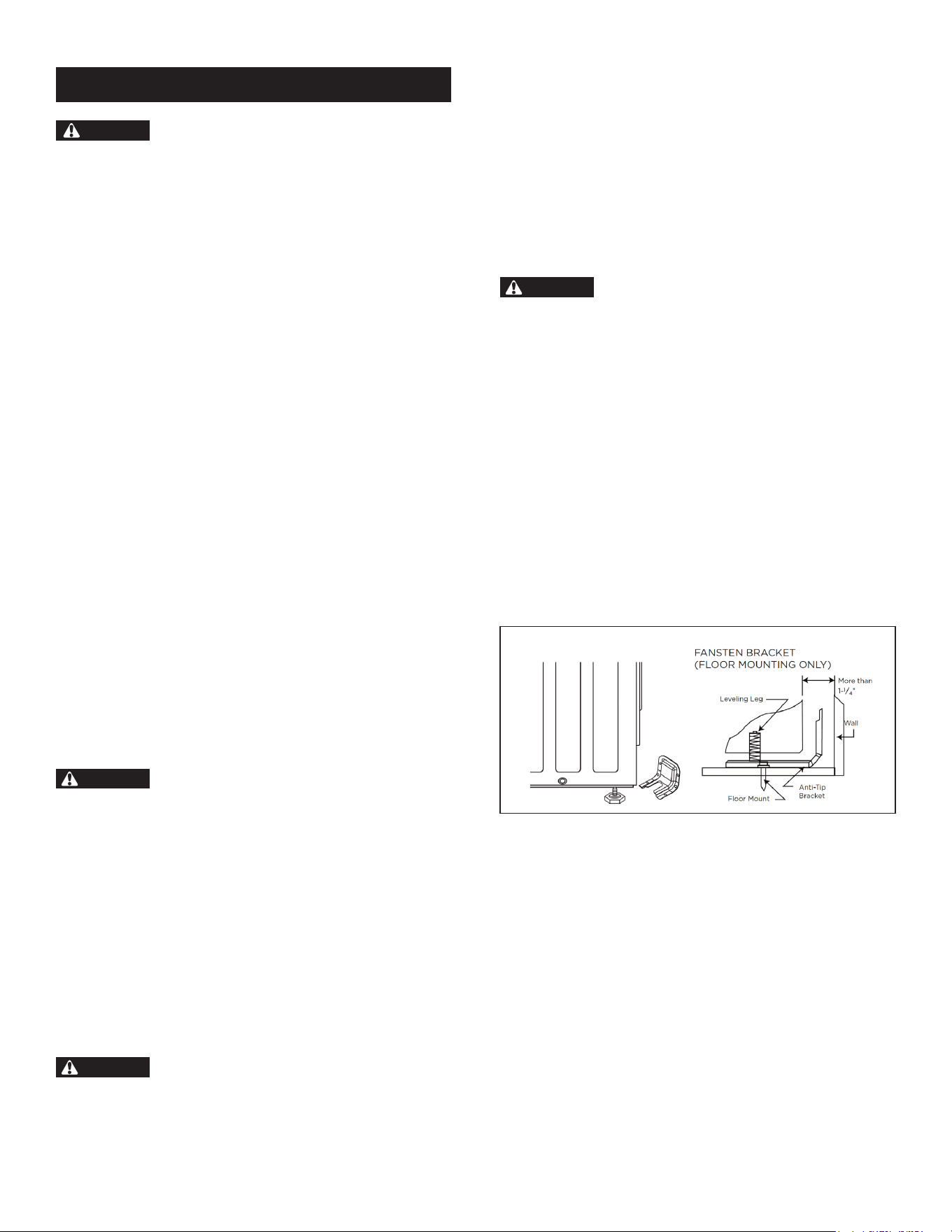
Clearances are based on standard counter and cabinet dimensions as
shown in the STANDARD DIMENSIONS chart below. See Figure
2 for required clearances.
STANDARD DIMENSIONS
Countertop height 36"
Countertop depth 25"
Countertop thickness 1
1
/2"
Cabinet height 34
1
/2"
Cabinet depth 24"
Distance between rangetop and upper cabinet 30"
CLEARANCES
The Freestanding Gas Range can be installed freestanding style with
no back splash or slide-in style. For both options, the cutout width
is the same, but the cutout depth is different. See the CUTOUT
DIMENSIONS chart below and Figure 3 for cutout requirements.
CUTOUT DIMENSIONS
FREESTANDING CUTOUT
Width 30"
Depth 25"
SLIDE-IN CUTOUT
Width 30"
Depth
23
11
/16"
FIGURE 2 FIGURE 3
NOTE:
• FOR ISLAND INSTALLATIONS, MAINTAIN 6'' MINIMUM FROM THE CUTOUT TO THE BACK AND
SIDE EDGES OF COUNTERTOP.
• OVERHEAD CABINETRY MUST BE AT LEAST 30" ABOVE THE COOKTOP SURFACE AND NOT
EXTEND MORE THAN 13" OVER THE COOKTOP SURFACE.
• MAINTAIN 0" CLEARANCE AT REAR AND SIDES OF THE RANGE.
NOTE:
• CUTOUT FOR SLIDE-IN INSTALLATION WITH NO REAR TRIM REQUIRED
IS 23 11/16" DEEP.
• HATCHED FACES OF COUNTERTOPS SHOULD BE FLAT AND LEVELED.
6"
30"
24" lower cabinet depth
13"
overhead
cabinet
depth
30"
36"
30"
18"
6
INSTALLATION PROCEDURE
CAUTION
LACERATION, FOREIGN OBJECT,
CRUSH HAZARD
• When installing, moving or servicing any appliance, wear proper
protective equipment, including cut resistant gloves, steel-toed
shoes and safety glasses.
IMPORTANT: Failure to remove packaging materials could result
in damage to the appliance.
1
Remove all tape and packaging materials. Check for lm on
stainless steel parts, padding/spacers on and around door and
face of oven, cardboard and plastic on and around racks, inside
storage drawer, etc.
Do not use sharp instruments, rubbing alcohol, ammable uids
or abrasive cleaners to remove tape or glue. These products can
damage the surface of your range.
2
Inventory all loose parts against the PARTS INCLUDED chart
on page 2.
Check for shipping damage and/or missing parts. Report any
damaged and/or missing parts to your local retailer.
3
To reduce the weight of the range while being moved, adjusted
and installed, set aside cooktop grates, cooktop burners, oven
racks and any other accessories until the unit is installed and
ready for use.
During installation, service, gas conversion and leveling, it is
recommended to remove the oven door and drawer. See the
Operation Manual for instructions on removing the oven door
and drawer.
4
Adjust and level the range height by rotating the leveling legs
so the overhang rests on the countertop surface with no gap.
Turn clockwise to raise the unit and counter-clockwise to lower.
OPTIONAL CONVERSIONS
LP GAS CONVERSION
WARNING
BURN, FIRE HAZARD
Failure to properly convert the range to the fuel type used at the
installation site can result in increased risk of re, burn injuries
and property damage. The conversion must be performed by a
qualied service technician in accordance with the manufacturer's
instructions and all local codes and requirements. The agency
performing this work assumes responsibility for the conversion.
The Freestanding Gas Range is preset for use with Natural Gas and
can be converted for use with Propane (LP) with the supplied LP
conversion kit. Conversion for use with propane must be perfor med
by a qualified technician in accordance with the installation
instructions and local codes. The agency performing this conversion
assumes responsibility for the conversion to propane use.
HIGH ALTITUDE CONVERSION
WARNING
CARBON MONOXIDE HAZARD
Reduced air pressure and oxygen availability at high altitudes
may affect proper burner combustion. Failure to properly convert
the range for high altitude installations can result in increased
risk carbon monoxide. The conversion must be performed by a
qualied service technician in accordance with the manufacturer's
instructions and all local codes and requirements. The agency
performing this work assumes responsibility for the conversion.
Units must be converted for proper operation at elevations in excess
of 6,000 feet. Contact a Sharp dealer to request a High Altitude
Conversion Kit. High altitude conversion requires all cooktop and
oven burner orices to be changed. Follow detailed instructions
included with the conversion kit. The regulator must be set according
to the fuel type in use at the installation site.
ANTI-TIP BRACKET
WARNING
TIP OVER HAZARD
• A child or adult can tip the range and be injured or killed. Verify
the anti-tip device has been properly installed and engaged per
installation instructions. Ensure the anti-tip device is re-engaged
when the range is moved.
• Do not operate the range without the anti-tip device in place and
engaged. Failure to follow this precaution can result in death or
serious burns to children or adults. Do not remove the leveling
legs. Doing so will prevent the range from being secured by the
anti-tip device.
To reduce the risk of tipping of the range, the range must be secured
to the oor by the properly installed Anti-Tip Bracket and screws
packed with the range. Failure to install the Anti-Tip Bracket will
allow the range to tip over if excessive weight is placed on an open
door or if a child climbs upon it. Serious injury might result from
spilled hot liquids or from the range itself.
TO INSTALL ANTI-TIP BRACKET
1
Using the template provided with the Anti-Tip Bracket, locate
the installation area of the Anti-Tip Bracket. The Anti-Tip
Bracket may be installed at either the back-left or back-right
corner of the installation space, and only one Anti-Tip Bracket
is necessary.
2
Mark the location of the screws for the Anti-Tip Bracket.
3
Attach the Anti-Tip Bracket to the oor or wall.
Wood Construction Installation: Drill a
1
/8" pilot hole where
screws are to be located. If bracket is to be mounted to the wall,
drill pilot hole at an approximate 20° downward angle. Screw must
enter wood.
Masonry Construction Installation: Due to the variety of masonry
materials that may be present at installation site, hardware is not
provided for attaching the Anti-Tip Bracket to masonry. If the
bracket is to be mounted to masonry or ceramic oors, attach using
two
5
/16" OD sleeve anchors (with
1
/4" bolt, either hex bolt head or
hex nut head) rated for minimum 300 lb tension for the masonry
material present at installation site.
7
GAS SUPPLY CONNECTION
WARNING
FIRE, EXPLOSION HAZARD
• Installation and service must be perfor med by a qualied installer,
service agency or the gas supplier.
• Installation must confor m with local codes or, in the absence of local
codes, with the National Fuel Gas Code, ANSI Z223.1/NFPA 54.
• Do not overtighten the connection to the regulator. The regulator
is die cast. Overtightening may crack the regulator resulting in a
gas leak and possible re or explosion.
• Do not use a ame to check for leaks.
• The agency performing this work assumes responsibility for the
quality of work performed, including checking for leaks and
ensuring installation meets code requirements.
TO CONNECT TO GAS SUPPLY
1
Shut off the main gas supply valve.
2
Because the range must be pulled away from the installation
space to provide access to the gas regulator connections, and
because hard piping restricts movement of the range, the range
can only be installed using a CSA Inter national-certied exible
metal appliance connector.
Contact Sharp Customer Service if local codes require a hard-
piped connection. Never use an old connector when installing
a new range.
3
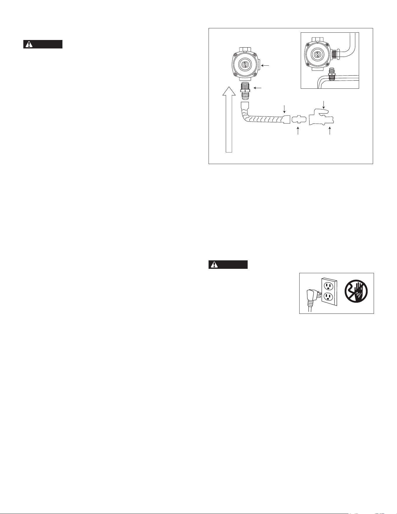
To prevent gas leaks, apply pipe-joint compound or wrap pipe-
thread tape with Teon on all male (external) pipe threads.
4
Install a manual gas line shut-off valve in the gas line in an easily
accessible location outside of the range. Instruct the consumer
on the location and operation of the shut-off valve.
5
As shown in Figure 4 below, install male
1
/2" are u nion adapter
to the
1
/2" NPT internal thread at the regulator inlet using no
more than 15 ft-lbs of torque. Use a backup wrench on the
regulator tting to avoid damage.
6
As shown in Figure 4 below, install male
1
/2" or
3
/4" are union
adapter to the NPT internal thread of the manual shut-off valve
using no more than 15 ft-lbs of torque, taking care to back up
the shutoff valve to keep it from turning.
7
Connect exible metal appliance connector to the adapter
on the range.
8
Position range to permit connection at the shut-off valve.
9
Connect exible metal appliance connector to the shut-off valve.
1
/2" adapter
1
/2" adapter
1
/2" adapter
1
/2" or
1
/4"
gas pipe
flex connector
gas flow into range
gas shut-off valve
pressure
regulator
FIGURE 4
10
When all connections have been made, leave the range pulled
out from installation space. Ensure the shut-off valve is open
and all range controls are in the off position.
11
Turn on the main gas supply valve and use a liquid leak detector
(or soap and water) at all joints and conduits to check for leaks
in the system.
12
Form the gas exible connector as shown. This will prevent the
exible connector from pinching or blocking the unit when the
unit is pushed into its nal position.
ELECTRICAL SUPPLY CONNECTION
WARNING
ELECTRICAL SHOCK HAZARD
• Installation must be electrically
grounded in accordance with
local codes or, in the absence of
local codes, with the National
Electrical Code, NFPA 70.
• Do not use an extension cord
with this product.
• The power supply cord and plug should not be modied. If
it will not t the outlet, have a proper outlet installed by a
qualied electrician.
• Remove the house fuse or open the circuit breaker before
beginning installation.
• The appliance must be properly installed and grounded by a
qualied service provider.
This appliance must be supplied with the proper voltage and
frequency (120V, 60Hz) and be connected to an individual, properly
grounded branch circuit protected by a circuit breaker or fuse having
amperage as specied on the rating plate. The rating plate is located
in the storage drawer. After installation, instruct the consumer where
the main range electrical disconnect is located and how to operate it.

8
PLACING UNIT
IMPORTANT: All ranges are heavy. Sliding the range can damage
the oor. Use care when moving the range. Use a belt when moving
the range to prevent damaging the oor. Use cardboard, plywood
or stiff plastic to avoid damaging the oor while sliding the range.
Getting the unit properly placed in the installation space and level
may require multiple attempts. It is recommended to measure and
adjust leveling legs carefully before placing into the installation
space, as the leveling legs may be difcult to adjust once the range
is in its nal position.
TO PLACE UNIT
1
Use tape measure to measure from the oor to the top of the
counter top at all four corners of the installation space.
2
While range is still positioned outside the installation space,
adjust the leveling leg at each corner so that the distance from
the oor to the underside of the cooktop edge matches the
dimensions measured in the installation space.
3
Using two people, move range into its nal installation location,
being careful not to damage countertops, oor or appliance.
NOTE:
• Do not move unit by pushing or pulling on the door or control
panel. Do not lift by the cooktop edges or display panel. Push,
pull or lift only on the body or structural areas, such as oven,
oven face or back corners of range.
• Be careful not to pinch or kink the gas or electrical
connections. If unit does not move in smoothly, check for
obstructions. Do not attempt to force the unit into position.
• Dampening the countertop where the cooktop overhangs
with soapy water may allow the range to slide into position
more smoothly.
4
Ensure the back leg of the range has engaged properly into the
Anti-Tip Bracket. If visual inspection is not possible:
• Slide range forward.
• Conrm Anti-Tip Bracket is securely attached to oor or wall
in correct position according to installation instructions.
• Fully slide the range back against the wall so that leveling
leg engages with Anti-Tip Bracket.
5
To ensure baked goods, such as breads and cakes, come out
even and level, conrm that the range is level by placing on
the center rack position. Check level both front-to-back and
side-to-side. Use adjustable pliers to adjust leveling legs as
necessary to level the range. Turn clockwise to raise the unit
and counter-clockwise to lower.
IMPORTANT: The weight of the product is to be suppor ted by
the leveling legs. When adjusting leveling legs, do not adjust so
far that the weight of the product is supported by the cooktop
resting on the countertop. If countertops are not level, leveling
the range may cause one or more corners of the cooktop to not
contact the countertop surface. If this occurs, the range can be
installed unleveled to allow the cooktop to contact the entire
perimeter. Be advised that this may affect performance for
some baked goods. In these cases, foam tape rated for 194 °F
minimum can be placed around countertop edge to ll the gap
caused by leveling. Do not use caulking or other adhesives that
would bind the cooktop to the counter.
6
Reinstall door, drawer and oven racks.
9
SURFACE BURNER ASSEMBLY
AND PLACEMENT
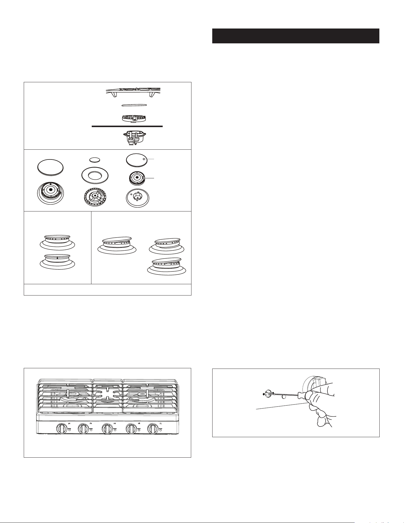
Position surface burner heads on top of the burner caps as shown.
Ensure the surface burner heads are at and parallel with the
cooktop. Place the matching size caps on top of each surface burner
head. See Figure 5.
burner grate
burner cap
burner
cooktop surface
ignitor
Cap
Spreader
CORRECT INCORRECT
FIGURE 5
Or ient the burner grates by nding the raised labels on the underside
of each grate. All grates are stamped with REAR on the underside
at the end of the grate that must be installed near the vents, and with
L indicating the left grate, M indicating the middle grate and R
indicating the right grate. Place the grates on the cooktop with ends
marked L REAR, M REAR and R REAR in the correct positions.
Grates are not interchangeable and must be placed correctly. See
Figure 6.
FIGURE 6
CONFIRM OPERATION
After the range has been installed and assembled, gas supply lines
have been carefully checked for leaks and the electrical power cord
has been connected, conrm the operation of all cooktop burners.
To purge any air that may remain inside the range gas tubing, it is
recommended to conrm operation of the cooktop burners before
conrming operation of the oven.
TO CONFIRM COOKTOP OPERATION
1
For each burner, testing one at a time, rotate the knob to the Lite
position. Conrm that clicking is heard and visually observe
the electrode sparking properly to the burner cap.
2
Allow a few seconds for the burner to ignite and observe ame
quality. Light all surface burners and set to the highest setting.
• Soft blue ames indicate normal operation for natural gas.
• Blue ames with yellow tips on the outer cones indicate
normal operation for LP gas.
• Yellow ames indicate abnormal operation for any gas.
Call for service.
3
For each bu r ner, compare ame height at the highest and lowest
setting and conrm Lo heat is sufciently low for the size of
burner being tested.
4
For each burner, rotate the knob quickly to the lowest setting
and conrm the ame is not extinguished.
5
Turn off all but one burner. With one burner still at the lowest
setting, quickly open and close the oven door and conrm the
ame is not extinguished.
6
If burner ame is extinguished during any of the above tests,
or if ames are unacceptably large at the lowest setting, adjust
the low ame setting.
TO ADJUST LOW FLAME SETTING
1
Light all surface burners. Set all burners at the highest setting,
except the one being adjusted. Set the burner being adjusted to
the lowest setting.
2
Remove the knob by pulling rmly straight out.
3
Insert a small, at-blade screwdriver into the valve shaft. Fit
tip of screwdriver into small screw head at base of valve shaft.
See Figure 7.
FIGURE 7
4
Holding the valve shaft with one hand to prevent it from turning,
turn the screwdriver to adjust ame height (counter-clockwise
increases ow; clockwise decreases ow).
5
Repeat for any burners requiring calibration at the lowest setting.
6
When adjustment is complete, repeat the full burner operation
testing described above.

10
TO CONFIRM OVEN OPERATION
1
Ensure all packaging is removed and oven is empty except for
oven racks. Close oven door.
2
Touch Bake pad on the control panel. The default temperature
is 350 °F. Use the numeric keypad to adjust the temperature
setting to 170 °F. Touch START/ENTER pad.
3
Listen for a clicking sound from the spark igniter followed by
a whoosh sound of ignition.
If the oven does not ignite immediately, the spark igniter will
only activate for a few seconds. If this happens, the oven control
will turn off the gas ow to the burner, wait 10-15 seconds, and
re-attempt ignition. It will make a total of 3 attempts before
generating an error. The entire process should take less than
1 minute.
4
It is normal for the oven control to attempt igniting 2 or 3 times
immediately after the unit is rst installed due to residual air in
the gas lines inside the range. If the oven takes multiple attempts
to ignite, cancel the bake mode and restart to conrm the oven
ig nites on the rst attempt. Once all air has been purged from the
gas lines, the oven should ignite immediately on rst attempt. If
oven continues to require multiple attempts to ignite, contact a
qualied service provider for investigation and repairs.
5
Allow Bake mode to operate until the oven has preheated to
170 °F. Conrm the display indicates the temperature increasing
and signals when the temperature is reached. Touch STOP/
CLEAR pad to stop the Bake mode.
6
Touch Broil pad on the control panel. Touch START/
ENTER pad.
7
Listen for a clicking sound from the spark igniter followed by
a whoosh sound of ignition. If the broil burner does not ignite
immediately, see step 3 above.
8
Observe the broil ame quality through the oven door window.
If ames do not carry all the way around the broil burner, this
may indicate air in the gas lines. Allow the burners to operate
for 1–2 minutes to purge the lines of any remaining air.
9
Touch STOP/CLEAR pad to stop Broil mode. If anything
does not operate correctly or if broil ames appear abnormal,
call for service.
MODEL AND SERIAL NUMBER
LOCATION
The model and serial number are needed when contacting
customer service and to register the product and order
replacement parts. The name plate label contains appliance
certication, rating and identication information. It is located
inside the storage drawer on either the left or right side panel.
CARE, CLEANING AND MAINTENANCE
Refer to the Operation Manual for cleaning instructions.
BEFORE YOU CALL FOR SERVICE
Read the BEFORE YOU CALL and operating instruction
sections in your Operation Manual. It may save you time and
expense. The list includes common occurrences that are not the
result of defective workmanship or materials in this appliance.
Refer to the warranty in your Operation Manual for Sharp’s
toll-free service number and address. Please call or write if you
have inquiries about your freestanding gas range and/or need
to order parts.
11
LP CONVERSION INSTRUCTIONS
Page 1 (insert document and rev #)
WARNING
FIRE, EXPLOSION, CARBON MONOXIDE HAZARDS
This conversion kit shall be installed by a qualified service agency in accordance with the
manufacturer’s instructions and all applicable codes and requirements of the authority
having jurisdiction. If the information in these instructions is not followed exactly, a fire,
explosion, or production of carbon monoxide may result causing loss of life, personal
injury, or property damage. The qualified service
agency is responsible for the proper
installation of this kit. The installation is not proper and complete until the operation of the
converted appliance is checked and conversion labels applied as specified in the
manufacturer’s instructions supplied with the kit.
Before proceeding with the conversion, shut off the gas supply before disconnecting electrical
power to the range. Be sure both power su
pplies are off before installing the conversion kit. Failure
to do so could cause s
erious bodily injury.
This conversion kit may be installed only on the following model(s):
Parts List:
Qty SHARP P/N Description
1 LP Conversion Instructions (this document)
1 16071100A4 8131 LP Conversion Label for Rating Plate
1 16071100A46896 LP Conversion Sign-Off Label for Rating Plate
1 16071100A46897 LP Conversion Warning Label
1 12971100018535
1.12mm orifice (marked “112”)
3 12971100018531
1.02mm orifice (marked “102”)
2 12971100A76318
0.86mm orifice (marked “86”)
1 12971100A76319
0.6
7mm orifice (marked “67”)
IMPORTANT: After replacing the natural gas to LP orifices, be sure to keep the original factory
installed natural gas orifices for future range conversion back to natural gas. The NG and LP orifices
are marked as follows:
Burner Location NG Orifice Markings LP Orifice Markings
Left Front 173 102
Left Rear 99 67
Right Front 173 102
Right Rear 136 86
Center 13 6 86
Bake 190
112
Broil 178 102
Tools Required:
Phillips screw driver
Narrow blade flat screwdriver
7mm or 9/32" hex driver
adjustable wrench
16 71100A341 649
SSG3061JS / SSG3065JS
LP CONVERSION INSTRUCTIONS
Page 1 (insert document and rev #)
WARNING
FIRE, EXPLOSION, CARBON MONOXIDE HAZARDS
This conversion kit shall be installed by a qualified service agency in accordance with the
manufacturer’s instructions and all applicable codes and requirements of the authority
having jurisdiction. If the information in these instructions is not followed exactly, a fire,
explosion, or production of carbon monoxide may result causing loss of life, personal
injury, or property damage. The qualified service
agency is responsible for the proper
installation of this kit. The installation is not proper and complete until the operation of the
converted appliance is checked and conversion labels applied as specified in the
manufacturer’s instructions supplied with the kit.
Before proceeding with the conversion, shut off the gas supply before disconnecting electrical
power to the range. Be sure both power su
pplies are off before installing the conversion kit. Failure
to do so could cause s
erious bodily injury.
This conversion kit may be installed only on the following model(s):
Parts List:
Qty SHARP P/N Description
1 LP Conversion Instructions (this document)
1 16071100A4 8131 LP Conversion Label for Rating Plate
1 16071100A46896 LP Conversion Sign-Off Label for Rating Plate
1 16071100A46897 LP Conversion Warning Label
1 12971100018535
1.12mm orifice (marked “112”)
3 12971100018531
1.02mm orifice (marked “102”)
2 12971100A76318
0.86mm orifice (marked “86”)
1 12971100A76319
0.67mm orifice (marked “67”)
IMPORTANT: After replacing the natural gas to LP orifices, be sure to keep the original factory
installed natural gas orifices for future range conversion back to natural gas. The NG and LP orifices
are marked as follows:
Burner Location NG Orifice Markings LP Orifice Markings
Left Front 173 102
Left Rear 99 67
Right Front 173 102
Right Rear 136 86
Center 13 6 86
Bake 190 112
Broil 178 102
Tools Required:
Phillips screw driver
Narrow blade flat screwdriver
7mm or 9/32" hex driver
adjustable wrench
16 71100A341 649
SSG3061JS / SSG3065JS
LP CONVERSION INSTRUCTIONS
Page 1 (insert document and rev #)
WARNING
FIRE, EXPLOSION, CARBON MONOXIDE HAZARDS
This conversion kit shall be installed by a qualified service agency in accordance with the
manufacturer’s instructions and all applicable codes and requirements of the authority
having jurisdiction. If the information in these instructions is not followed exactly, a fire,
explosion, or production of carbon monoxide may result causing loss of life, personal
injury, or property damage. The qualified service agency is responsible for the proper
installation of this kit. The installation is not proper and complete until the operation of the
converted appliance is checked and conversion labels applied as specified in the
manufacturer’s instructions supplied with the kit.
Before proceeding with the conversion, shut off the gas supply before disconnecting electrical
power to the range. Be sure both power supplies are off before installing the conversion kit. Failure
to do so could cause s
erious bodily injury.
This conversion kit may be installed only on the following model(s):
Parts List:
Qty Midea P/N Description
1 LP Conversion Instructions (this document)
1 16071100A4 8131 LP Conversion Label for Rating Plate
1 16071100A46896 LP Conversion Sign-Off Label for Rating Plate
1 16071100A46897 LP Conversion Warning Label
1 12971100018535
1.12mm orifice (marked “112”)
3 12971100018531
1.02mm orifice (marked “102”)
2 12971100A76318
0.86mm orifice (marked “86”)
1 12971100A76319
0.67mm orifice (marked “67”)
IMPORTANT: After replacing the natural gas to LP orifices, be sure to keep the original factory
installed natural gas orifices for future range conversion back to natural gas. The NG and LP orifices
are marked as follows:
Burner Location NG Orifice Markings LP Orifice Markings
Left Front 173 102
Left Rear 99 67
Right Front 173 102
Right Rear 136 86
Center 13 6 86
Bake 190 112
Broil 178 102
Tools Required:
Phillips screw driver
Narrow blade flat screwdriver
7mm or 9/32" hex driver
adjustable wrench
16 71100A341 649
SSG3061JS / SSG3064SNS / SSG3062DNS / SSG3074SNS / SSG3076SNS
SFG3075MS
Qty SHARP P/N Description
1 9KL12971100A86313 LP Conversion Kit
1 16171100A34649 LP Conversion Instructions (this document)
1 16071100A48131 LP Conversion Label for Rating Plate
1 16071100A46896 LP Conversion Sign-Off Label for Rating Plate
1 16071100A46897 LP Conversion Warning Label
1 12971100018535 1.12mm orice (marked “112”)
3 12971100018531 1.02mm orice (marked “102”)
2 12971100A76318 0.86mm orice (marked “86”)
1 12971100A76319 0.67mm orice (marked “67”)
■
■
■
■
12
Page 2 (insert document and rev #)
Instruction Steps:
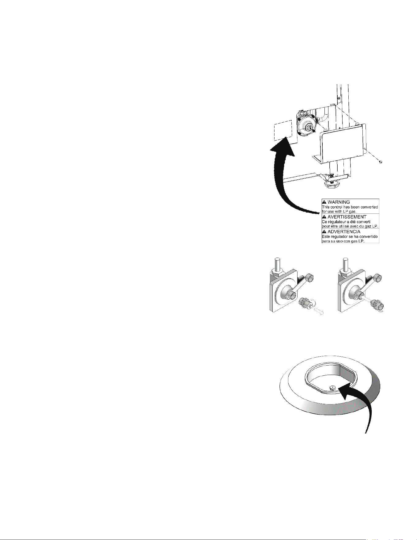
1. Convert the pressure regulator
To access the pressure regulator, the appliance must be
removed from the installation space.
Remove the regulator access cover from the bottom-right
corner of the back of the appliance (as viewed from the
back).
Do NOT remove the pressure regulator or allow it to
turn.
If present, remove the plastic dust cover from the
regulator plug.
Using an adjustable wrench, unscrew the regulator plug
from the pressure regulator - do not remove the spring
from the regulator.
Orient the plug for the fuel type being used.
NG will have the hollow end of the plug towards the
regulator and spring.
LP will have the hollow end of the plug facing away
from the regulator.
Plug direction is also stamped on the side of the plug.
Replace the plug and dust cover onto the regulator.
Reinstall the regulator access cover
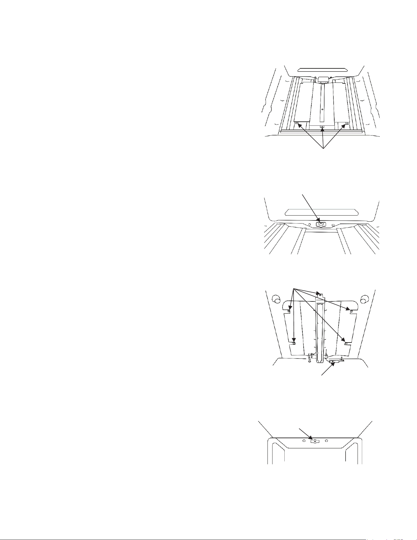
Apply the “LP Conversion Warning Label” on the rear wire
cover on or near the access cover.
2. Replace cooktop orifices
Remove the top grates, burner caps, and burner heads
Using a 7mm or 9/32″ nut driver, remove the top burner
orifices. These may be accessed through the burner
opening in the base. Keep the original Natural Gas orifices
for later conversion to Natural Gas.
Locate the cooktop LP orifices provided with this kit. Each
orifice is permanently stamped with numbers indicating the
size of the orifice opening. (See orifice marking table on
page 1 of these instructions.)
Using a 7mm or 9/32″ nut driver, install each of the LP
orifices in the correct location according to the table on
page 1. Tighten each orifice until snug. Use caution not to
overtighten.
Replace burners, burner caps, and grates to their
respective locations.
Cooktop burner orifice
location
LP CONVERSION INSTRUCTIONS
Page 2 (insert document and rev #)
Instruction Steps:
1. Convert the pressure regulator
To access the pressure regulator, the appliance must be
removed from the installation space.
Remove the regulator access cover from the bottom-right
corner of the back of the appliance (as viewed from the
back).
Do NOT remove the pressure regulator or allow it to
turn.
If present, remove the plastic dust cover from the
regulator plug.
Using an adjustable wrench, unscrew the regulator plug
from the pressure regulator - do not remove the spring
from the regulator.
Orient the plug for the fuel type being used.
NG will have the hollow end of the plug towards the
regulator and spring.
LP will have the hollow end of the plug facing away
from the regulator.
Plug direction is also stamped on the side of the plug.
Replace the plug and dust cover onto the regulator.
Reinstall the regulator access cover
Apply the “LP Conversion Warning Label” on the rear wire
cover on or near the access cover.
2. Replace cooktop orifices
Remove the top grates, burner caps, and burner heads
Using a 7mm or 9/32″ nut driver, remove the top burner
orifices. These may be accessed through the burner
opening in the base. Keep the original Natural Gas orifices
for later conversion to Natural Gas.
Locate the cooktop LP orifices provided with this kit. Each
orifice is permanently stamped with numbers indicating the
size of the orifice opening. (See orifice marking table on
page 1 of these instructions.)
Using a 7mm or 9/32″ nut driver, install each of the LP
orifices in the correct location according to the table on
page 1. Tighten each orifice until snug. Use caution not to
overtighten.
Replace burners, burner caps, and grates to their
respective locations.
Cooktop burner orifice
location
LP CONVERSION INSTRUCTIONS
Apply the “LP Conversion Warning Label” on the rear wire
cover or near the access cover
Locate the cooktop LP orices provided with this kit. Each
orice is permanently stamped with numbers indicating the
size of the orice opening. (See orice marking table on
page 11 of these instructions.)
Using a 7mm or 9/32" nut driver, install each of the LP
orices in the correct location according to the table on
page 11. Tighten each orice until snug. Use caution not to
overtighten.
13
Page 3 (insert document and rev #)
3. Replace bake orifice
Orifice cannot be converted by tightening the orifice - the
orifice must be replaced.
Remove the oven door (see Use & Care Manual or
Installation Instructions for details.
Remove oven bottom by removing the 2 screws at the
front of the oven bottom hidden behind the door gasket.
Remove the screws holding the flame spreader and burner
to the burner box.
Carefully pull out bake burner assembly, and tip the
assembly upwards to reveal the bake orifice behind the
oven back. Lean the assembly out of the way, being
careful not to damage electrode or flame sense wires.
Use a 7mm or 9/32″ nut driver to remove the bake orifice
from the orifice holder. Be careful to not drop the orifice.
Locate the oven LP orifices provided with this kit. (See
orifice marking table on page 1 of these instructions.)
Using a 7mm or 9/32″ nut driver, install the LP orifice into
the bake orifice holder. Tighten orifice until snug. Use
caution not to overtighten.
Reinstall the bake burner assembly and oven bottom,
being careful to not pinch or damage the door gasket.
4. Replace broil orifice
Orifice cannot be converted by tightening the orifice - the
orifice must be replaced.
The broil burner is attached to the flame spreader - both
parts can be removed together. Remove 1 screw from
flame sensor wire cover on back of oven cavity. Remove
the screws holding the burner assembly to the oven top.
Carefully pull burner assembly away from the oven top,
and tip the assembly downwards to reveal the broil orifice
behind the oven back. Lean the assembly out of the way,
being careful not to damage electrode or flame sense
wires.
Use a 7mm or 9/32″ nut driver to remove the broil orifice
from the orifice holder. Be careful to not drop the orifice.
Locate the oven LP orifices provided with this kit. (See
orifice marking table on page 1 of these instructions.)
Using a 7mm or 9/32″ nut driver, install the LP orifice into
the bake orifice holder. Tighten orifice until snug. Use
caution not to overtighten.
Reinstall the broil burner assembly, flame sensor wire
cover, and oven door.
Screws
Bake Orifice
Broil Orifice
Screws
Flame Sensor
Wire Cover
LP CONVERSION INSTRUCTIONS
Page 3 (insert document and rev #)
3. Replace bake orifice
Orifice cannot be converted by tightening the orifice - the
orifice must be replaced.
Remove the oven door (see Use & Care Manual or
Installation Instructions for details.
Remove oven bottom by removing the 2 screws at the
front of the oven bottom hidden behind the door gasket.
Remove the screws holding the flame spreader and burner
to the burner box.
Carefully pull out bake burner assembly, and tip the
assembly upwards to reveal the bake orifice behind the
oven back. Lean the assembly out of the way, being
careful not to damage electrode or flame sense wires.
Use a 7mm or 9/32″ nut driver to remove the bake orifice
from the orifice holder. Be careful to not drop the orifice.
Locate the oven LP orifices provided with this kit. (See
orifice marking table on page 1 of these instructions.)
Using a 7mm or 9/32″ nut driver, install the LP orifice into
the bake orifice holder. Tighten orifice until snug. Use
caution not to overtighten.
Reinstall the bake burner assembly and oven bottom,
being careful to not pinch or damage the door gasket.
4. Replace broil orifice
Orifice cannot be converted by tightening the orifice - the
orifice must be replaced.
The broil burner is attached to the flame spreader - both
parts can be removed together. Remove 1 screw from
flame sensor wire cover on back of oven cavity. Remove
the screws holding the burner assembly to the oven top.
Carefully pull burner assembly away from the oven top,
and tip the assembly downwards to reveal the broil orifice
behind the oven back. Lean the assembly out of the way,
being careful not to damage electrode or flame sense
wires.
Use a 7mm or 9/32″ nut driver to remove the broil orifice
from the orifice holder. Be careful to not drop the orifice.
Locate the oven LP orifices provided with this kit. (See
orifice marking table on page 1 of these instructions.)
Using a 7mm or 9/32″ nut driver, install the LP orifice into
the bake orifice holder. Tighten orifice until snug. Use
caution not to overtighten.
Reinstall the broil burner assembly, flame sensor wire
cover, and oven door.
Screws
Bake Orifice
Broil Orifice
Screws
Flame Sensor
Wire Cover
LP CONVERSION INSTRUCTIONS
Orice cannot be converted - the bake orice must be
replaced.
Locate the oven LP orices provided with this kit. (See
orice marking table on page 11 of these instructions.)
Orice cannot be converted - the broil orice must be
replaced.
Locate the oven LP orices provided with this kit. (See
orice marking table on page 11 of these instructions.)
14
Page 4 (insert document and rev #)
5. Verify Operation
Test if cooktop burner “low” setting requires adjustment, for each burner, perform the
following:
Push in and turn control to LITE until burner ignites.
Quickly turn knob to LOWEST POSITION.
If burner goes out, reset control to OFF.
Remove the surface burner control knob.
Insert a thin-bladed screwdriver into the hollow
valve stem and engage the slotted screw inside.
Flame size can be increased or decreased by
turning the screw. Turn counterclockwise to
increase flame size. Turn clockwise to decrease
flame size. Adjust flame until you can quickly turn
knob from LITE to LOWEST POSITION without
extinguishing the flame. Flame should be as small
as possible without going out.
Cooktop/Oven Burner Flame Appearance:
Flames should be mostly blue. Yellow tips on outer cone of flames is normal for
propane fuel.
Oven burners do not have an adjustable air shutter. If flames are oversized or overly
yellow, confirm correct orifices have been installed, house gas supply pressure is
correct, and cooktop manifold gas pressure is within specifications.
Check manifold gas pressure (if necessary): If it should be necessary to check the
manifold gas pressure, follow these steps:
Remove the burner cap from the right-rear burner.
Connect pressure gauge to right-rear orifice using rubber hose with inside diameter
~1/4”. Hold tubing down tight over orifice.
Light another cooktop burner and turn to a medium-low setting.
Turn right-rear burner valve on.
Confirm pressure reading is ~5” WC for NG or 10” WC for LP.
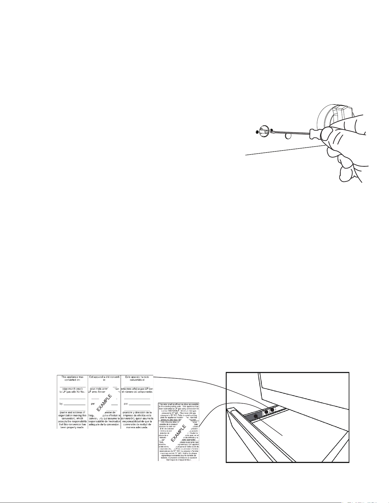
6. Label Unit for Conversion
Place the “LP Conversion Label for Rating Plate” beside the existing rating plate inside
the left side of the storage drawer.
Fill out the “LP Conversion Sign-Off Label for Rating Plate” and place it beside the
existing rating plate label.
existing rating
plate label
10/29/2020
MKIT4LPHA
Acme Applianc
e
520 W. Colfax, Denver, CO
LP CONVERSION INSTRUCTIONS
Page 4 (insert document and rev #)
5. Verify Operation
Test if cooktop burner “low” setting requires adjustment, for each burner, perform the
following:
Push in and turn control to LITE until burner ignites.
Quickly turn knob to LOWEST POSITION.
If burner goes out, reset control to OFF.
Remove the surface burner control knob.
Insert a thin-bladed screwdriver into the hollow
valve stem and engage the slotted screw inside.
Flame size can be increased or decreased by
turning the screw. Turn counterclockwise to
increase flame size. Turn clockwise to decrease
flame size. Adjust flame until you can quickly turn
knob from LITE to LOWEST POSITION without
extinguishing the flame. Flame should be as small
as possible without going out.
Cooktop/Oven Burner Flame Appearance:
Flames should be mostly blue. Yellow tips on outer cone of flames is normal for
propane fuel.
Oven burners do not have an adjustable air shutter. If flames are oversized or overly
yellow, confirm correct orifices have been installed, house gas supply pressure is
correct, and cooktop manifold gas pressure is within specifications.
Check manifold gas pressure (if necessary): If it should be necessary to check the
manifold gas pressure, follow these steps:
Remove the burner cap from the right-rear burner.
Connect pressure gauge to right-rear orifice using rubber hose with inside diameter
~1/4”. Hold tubing down tight over orifice.
Light another cooktop burner and turn to a medium-low setting.
Turn right-rear burner valve on.
Confirm pressure reading is ~5” WC for NG or 10” WC for LP.
6. Label Unit for Conversion
Place the “LP Conversion Label for Rating Plate” beside the existing rating plate inside
the left side of the storage drawer.
Fill out the “LP Conversion Sign-Off Label for Rating Plate” and place it beside the
existing rating plate label.
existing rating
plate label
10/29/2020
MKIT4LPHA
Acme Applianc
e
520 W. Colfax, Denver, CO
LP CONVERSION INSTRUCTIONS


SHARP ELECTRONICS CORPORATION • 100 Paragon Drive • Montvale, New Jersey 07645 • USA
1-800-BE-SHARP (1-800-237-4277)
TINSEB783MRR0 JUNE 04, 2026