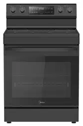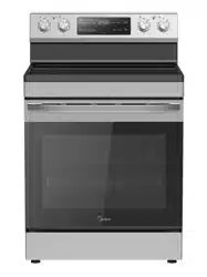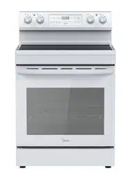
USER MANUAL
MMO17S6AST
MMO17S6AWW
MMO17S6ABB
MICROWAVE OVEN
Warning notices: Before using this product, please read this manual carefully and keep it for future reference.
The design and specifications are subject to change without prior notice for product improvement. Consult
with your dealer or manufacturer for details.
The diagram above is just for reference. Please take the appearance of the actual product as the standard.

02
CONTENTS
THANK YOU LETTER --------------------------------------------- 02
SAFETY INSTRUCTIONS----------------------------------------- 03
SPECIFICATION
--------------------------------------------------- 13
PRODUCT OVERVIEW ------------------------------------------- 14
PRODUCT INSTALLATION -------------------------------------- 16
OPERATION ------------------------------------------------------- 46
TROUBLESHOOTING --------------------------------------------- 58
TRADEMARKS, COPYRIGHTS AND LEGAL STATEMENT --- 59
DISPOSAL AND RECYCLING ------------------------------------ 60
DATA PROTECTION NOTICE ------------------------------------61
TWO YEAR LIMITED WARRANTY --------------------------------62
THANK YOU LETTER
Thank you for choosing Midea! Before using your new Midea product, please
read this manual thoroughly to ensure that you know how to operate the
features and functions that your new appliance offers in a safe way.
03
SAFETY INSTRUCTIONS
Intended Use
The following safety guidelines are intended to prevent unforeseen risks or damage from
unsafe or incorrect operation of the appliance. Please check the packaging and appliance
on arrival to make sure everything is intact to ensure safe operation. If you find any
damage, please contact the retailer or dealer. Please note modifications or alterations
to the appliance are not allowed for your safety concern. Unintended use may cause
hazards and loss of warranty claims.
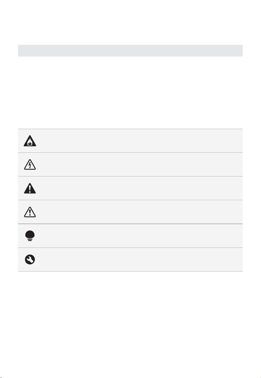
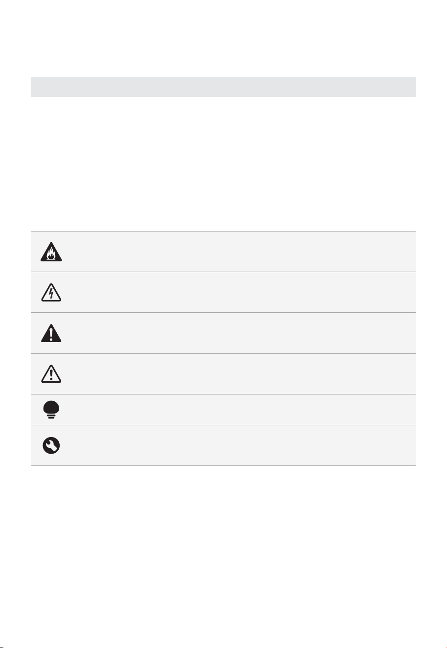
Explanation of Symbols
Danger
This symbol indicates that there are dangers to the life and health of persons due
to extremely flammable gas.
Warning of electrical voltage
This symbol indicates that there is a danger to life and health of persons due to
voltage.
Warning
The signal word indicates a hazard with a medium level of risk which, if not
avoided, may result in death or serious injury.
Caution
The signal word indicates a hazard with a low degree of risk which, if not avoided,
may result in minor or moderate injury.
Attention
The signal word indicates important information (e.g. damage to property), but
not danger.
Observe instructions
This symbol indicates that a service technician should only operate and maintain
this appliance in accordance with the operating instructions.
Read these operating instructions carefully and attentively before using/commissioning
the unit and keep them in the immediate vicinity of the installation site or unit for later use!

04
PRECAUTIONS TO AVOID
POSSIBLE EXPOSURE TO
EXCESSIVE MICROWAVE ENERGY
a. Do not attempt to operate this oven with the
door open since open door operation can result in
harmful exposure to microwave energy.
It is important not to defeat or tamper with the
safety interlocks.
b. Do not place any object between the oven front
face and the door or allows soil or cleaner residue
to accumulate on sealing surfaces.
c. Do not operate the oven if it is damaged. It is
particularly important that the oven door close
properly and that there is no damage to the:
- DOOR (bent)
- HINGES AND LATCHES (broken or loosened)
- DOOR SEALS AND SEALING SURFACES
d. The oven should not be adjusted or repaired by
anyone except properly qualified service personnel.
05
IMPORTANT SAFETY
INSTRUCTIONS
When using electrical appliances basic safety
precautions should be followed, including the following:
WARNING
To reduce the risk of burns, electric shock, fire, injury
to persons or exposure to excessive microwave energy:
1. Read all instructions before using the appliance.
2. Read and follow the specific: "PRECAUTIONS
TO AVOID POSSIBLE EXPOSURE TO EXCESSIVE
MICROWAVE ENERGY" found on page 04.
3. This appliance must be grounded. Connect only
to properly grounded outlet. See "GROUNDING
INSTRUCTIONS" found on page 08.
4. Install or locate this appliance only in accordance
with the provided installation instructions.
5. Some products such as whole eggs and sealed
containers - for example, closed glass jars - are able
to explode and should not be heated in this oven.
6. Use this appliance only for its intended use as
described in the manual. Do not use corrosive
chemicals or vapors in this appliance. This type of
oven is specifically designed to heat, cook or dry
food. It is not designed for industrial or laboratory
use.
7. HOT CONTENTS CAN CAUSE SEVERE BURNS. DO
NOT ALLOW CHILDREN TO USE THE MICROWAVE.
Use caution when removing hot items.
8. Do not operate this appliance if it has a damaged
cord or plug, if it is not working properly, or if it has
been damaged or dropped.
9. This appliance should be serviced only by qualified
service personnel. Contact nearest authorized

06
service facility for examination, repair, or adjustment.
10. Do not cover or block any openings on the
appliance.
11. Do not store this appliance outdoors. Do not use
this product near water - for example, near a
kitchen sink, in a wet basement, near a swimming
pool, or similar location.
12. Do not immerse cord or plug in water.
13. Keep cord away from heated surface.
14. Do not let cord hang over edge of table or counter.
15. When cleaning surfaces of door and oven that
comes together on closing the door, use only mild,
nonabrasive soaps, or detergent applied with a
sponge or soft cloth.
16. To reduce the risk of fire in the oven cavity:
1). Do not overcook food. Carefully attend
appliance when paper, plastic, or other
combustible materials are placed inside the
oven to facilitate cooking.
2). Remove wire twist-ties from paper or plastic
bag before placing bag in oven.
3). If material inside of the oven ignite, keep oven
door closed, turn oven off, and disconnect the
power cord, or shut off power at the fuse or
circuit breaker panel.
4). Do not use the cavity for storage purposes. Do
not leave paper products, cooking utensils, or
food in the cavity when not in use.
17. Liquids, such as water, coffee, or tea are able to
be overheated beyond the boiling point without
appearing to be boiling. Visible bubbling or boiling
when the container is removed from the microwave
oven is not always present.
THIS COULD RESULT IN VERY HOT
LIQUIDSUDDENLY BOILING OVER WHEN THE
CONTAINERIS DISTURBED OR A SPOON OR
OTHER UTENSIL IS INSERTED INTO THE LIQUID.

07
To reduce the risk of injury to persons:
1) Do not overheat the liquid.
2) Stir the liquid both before and halfway through
heating it.
3) Do not use straight-sided containers with
narrow necks.
4) After heating, allow the container to stand in
the microwave oven for a short time before
removing the container.
5) Use extreme care when inserting a spoon or
other utensil into the container.
18. Do not operate any heating or cooking appliance
beneath the appliance. (Exception: A microwave
oven investigated for use above another heating
appliance.)
19. Do not mount unit over or near any portion of
heating or cooking appliance. (Exception: A
microwave oven investigated for use above another
heating appliance.)
20. Do not mount over sink.
21. Do not store anything directly on top of the
appliance surface when the appliance is in operation.
22. Clean Ventilation Hoods Frequently - Grease should
not be allowed to accumulate on hood or filter.
23. When flaming foods under the hood, turn the fan
on.
24. Use care when cleaning the vent-hood filter.
Corrosive cleaning agents, such as lyebased oven
cleaners, may damage the filter.
25. Suitable for use above both gas and electric
cooking equipment.
SAVE THESE INSTRUCTIONS
HOUSEHOLD USE ONLY
(NOT FOR COMMERCIAL USE)
08
GROUNDING INSTALLATION
This appliance must be grounded. In the event of an
electrical short circuit, grounding reduces the risk of
electric shock by providing an escape wire for the
electric current. This appliance is equipped with a cord
having a grounding wire with a grounding plug. The
plug must be plugged into an outlet that is properly
installed and grounded.
WARNING
Improper use of the grounding can result in a risk of
electric shock.
Consult a qualified electrician or serviceman if the
grounding instructions are not completely understood,
or if doubt exists as to whether the appliance is
properly grounded. If it is necessary to use an
extension cord, use only a 3-wire extension cord that
has a 3-blade grounded plug, and 3-slot receptacle
that will accept the plug on the appliance. The marked
rating of the extension cord shall be equal to or greater
than the electrical rating of the appliance.
DANGER
Electric Shock Hazard:
Touching some of the internal components can cause
serious personal injury or death. Do not disassemble
this appliance.
WARNING
Electric Shock Hazard
Improper use of the grounding can result in electric
shock. Do not plug into an outlet until appliance is
properly installed and grounded.

09
A short power-supply cord is provided to reduce the
risks resulting from becoming entangled in or tripping
over a longer cord.
Longer cord sets or extension cords are available and
may be used if care is exercised in their use.
If a long cord or extension cord is used:
1) The marked electrical rating of the cord set or
extension cord should be at least as great as the
electrical rating of the appliance.
2) The extension cord must be a grounding-type
3-wire cord.
3) The longer cord should be arranged so that it will
not drape over the counter top or tabletop where
it can be pulled on by children or tripped over
unintentionally.
CLEANING
Be sure to unplug the appliance from the power supply.
1. Clean the cavity of the oven after using with a slightly
damp cloth.
2. Clean the accessories in the usual way in soapy water.
3. The door frame and seal and neighbouring parts must
be cleaned carefully with a damp cloth when they are
dirty.
4. Do not use harsh abrasive cleaners or sharp metal
scrapers to clean the oven door glass since they can
scratch the surface, which may result in shattering of
the glass.
5. Cleaning Tip---For easier cleaning of the cavity walls
that the food cooked can touch: Place half a lemon in
a bowl, add 300ml (1/2 pint) water and heat on 100%
microwave power for 10 minutes. Wipe the oven clean
using a soft, dry cloth.

10
RADIO INTERFERENCE
• Operation of the microwave oven may cause
interference to your radio, TV or similar equipment.
• When there is interference, it may be reduced or
eliminated by taking the following measures:
1) Clean door and sealing surface of the oven.
2) Reorient the receiving antenna of radio or
television.
3) Relocate the microwave oven with respect to the
receiver.
4) Move the microwave oven away from the receiver.
5) Plug the microwave oven into a different outlet so
that microwave oven and receiver are on different
branch circuits.
• This equipment generates, uses and can radiate radio
frequency energy and, if not installed and used in
accordance with the instructions, may cause harmful
interference to radio communications. However, there
is no guarantee that interference will not occur in a
particular installation. If this equipment does cause
harmful interference to radio or television reception,
which can be determined by turning the equipment
off and on, the user is encouraged to try to correct
the interference by one or more of the following
measures:
— Reorient or relocate the receiving antenna.
— Increase the separation between the equipment
and receiver.
— Connect the equipment into an outlet on a
circuit different from that to which the receiver is
connected.
— Consult the dealer or an experienced radio/TV
technician for help.
This device complies with part 18 of the FCC Rules.
11
UTENSILS
CAUTION
Personal Injury Hazard:
Tightly-closed utensils could explode. Closed
containers should be opened and plastic pouches
should be pierced before cooking.
See the instructions on "Materials you can use in
microwave oven or to be avoided in microwave oven."
There may be certain non-metallic utensils that are not
safe to use for microwaving. If in doubt, you can test
the utensil in question following the procedure below.
Utensil Test:
• Fill a microwave-safe container with 1 cup of cold
water (250ml) along with the utensil in question.
• Cook on maximum power for 1 minute.
• Carefully feel the utensil. If the empty utensil is warm,
do not use it for microwave cooking.
• Do not exceed 1 minute cooking time.
12
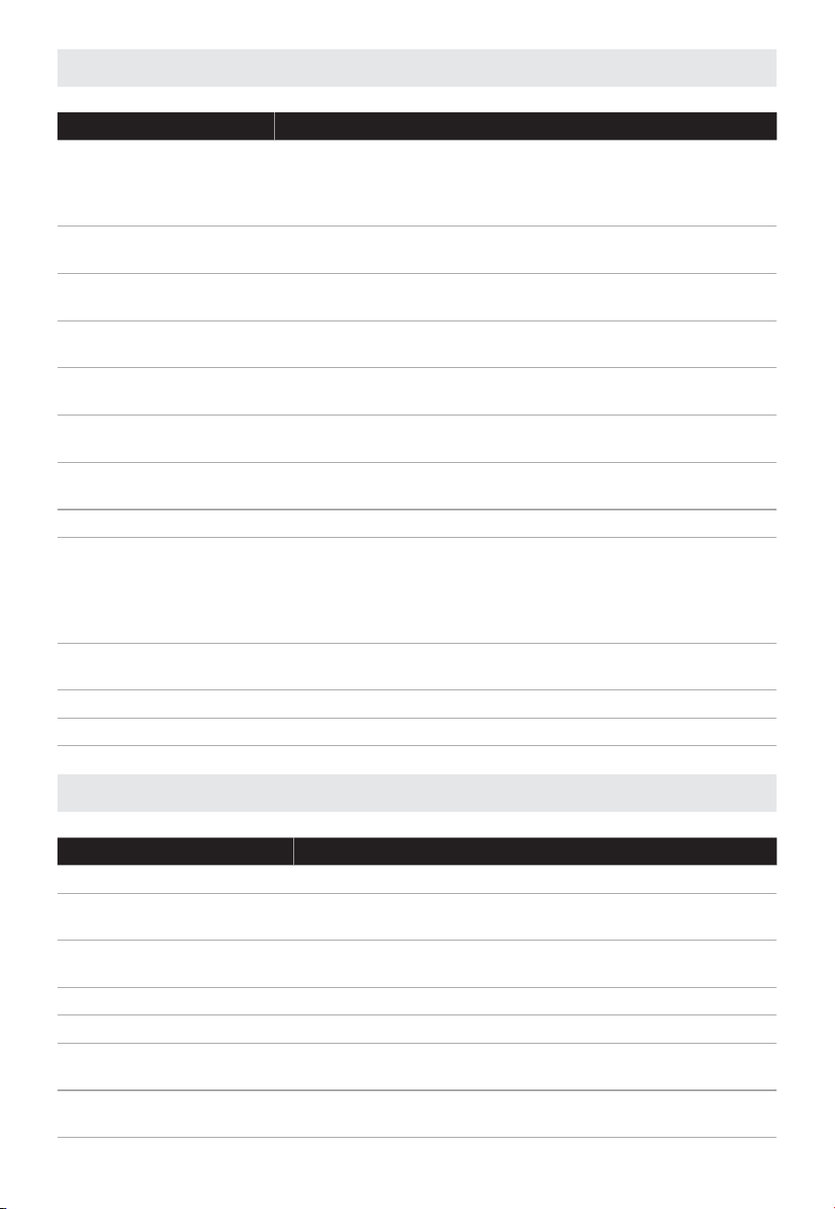
Materials you can use in microwave oven
Utensils Remarks
Browning dish
Follow manufacturer’s instructions. The bottom of browning
dish must be at least 3/16 inch (5mm) above the turntable.
Incorrect usage may cause the turntable to break. (For the
model with turntable.)
Dinnerware
Microwave-safe only. Follow manufacturer's instructions. Do
not use cracked or chipped dishes.
Glass jars
Always remove lid. Use only to heat food until just warm.
Most glass jars are not heat resistant and may break.
Glassware
Heat-resistant oven glassware only. Make sure there is no
metallic trim. Do not use cracked or chipped dishes.
Oven cooking bags
Follow manufacturer’s instructions. Do not close with metal
tie. Make slits to allow steam to escape.
Paper plates and cups
Use for short–term cooking/warming only. Do not leave
oven unattended while cooking.
Paper towels
Use to cover food for reheating and absorbing fat. Use with
supervision for a short-term cooking only.
Parchment paper Use as a cover to prevent splattering or a wrap for steaming.
Plastic
Microwave-safe only. Follow the manufacturer’s instructions.
Should be labeled "Microwave Safe". Some plastic containers
soften, as the food inside gets hot. "Boiling bags" and tightly
closed plastic bags should be slit, pierced or vented as
directed by package.
Plastic wrap
Microwave-safe only. Use to cover food during cooking to
retain moisture. Do not allow plastic wrap to touch food.
Thermometers Microwave-safe only (meat and candy thermometers).
Wax paper Use as a cover to prevent splattering and retain moisture.
Materials to be avoided in microwave oven
Utensils Remarks
Aluminum tray May cause arcing. Transfer food into microwave-safe dish.
Food carton with metal
handle
May cause arcing. Transfer food into microwave-safe dish.
Metal or metal-trimmed
utensils
Metal shields the food from microwave energy. Metal trim
may cause arcing.
Metal twist ties May cause arcing and could cause a fire in the oven.
Paper bags May cause a fire in the oven.
Plastic foam
Plastic foam may melt or contaminate the liquid inside
when exposed to high temperature.
Wood
Wood will dry out when used in the microwave oven and
may split or crack.

13
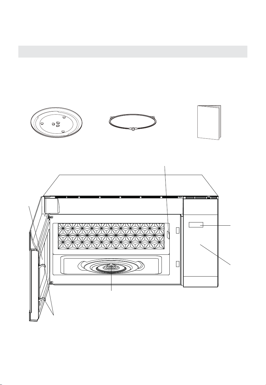
SPECIFICATION
Model
MMO17S6AST/MMO17S6AWW/MMO17S6ABB
Power Supply
120VAC 60Hz
Microwave Input 1500 W
Microwave Output 1000 W
14
PRODUCT OVERVIEW
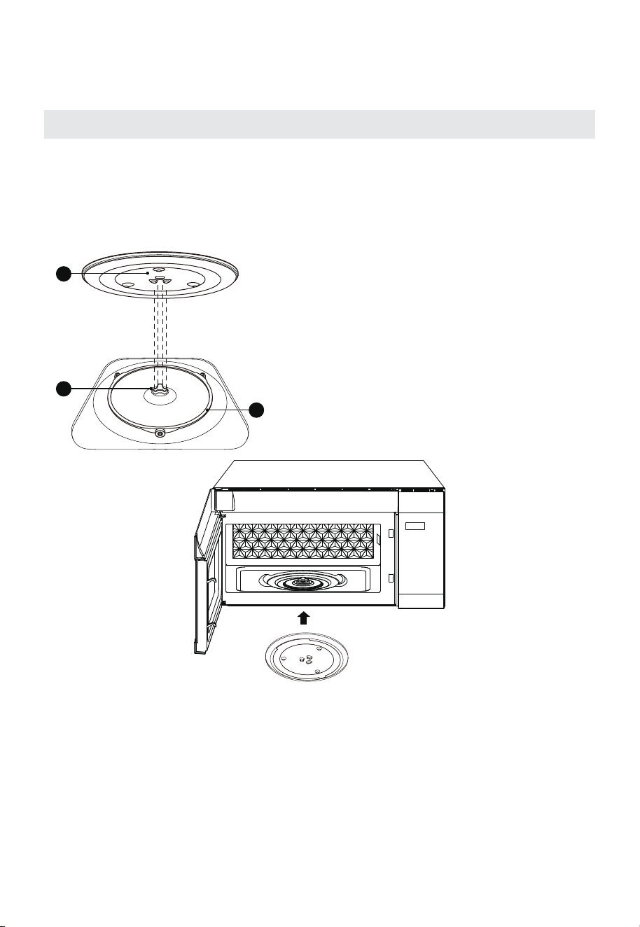
Names of Oven Parts and Accessories
In case of any differences between the appliance and the pictures in this manual,
the product shall prevail.
Remove the oven and all materials from the carton and oven cavity.
Your oven comes with the following accessories:
Glass Tray Turntable Ring Assembly Instruction Manual
1
2
4
5
6
3
1 Safety Door Latches
2 Observation Window
3 Turntable Motor Shaft
4 Waveguide Cover
5 Display Screen
6 Control Panel
15
PRODUCT OVERVIEW
TURNTABLE INSTALLATION
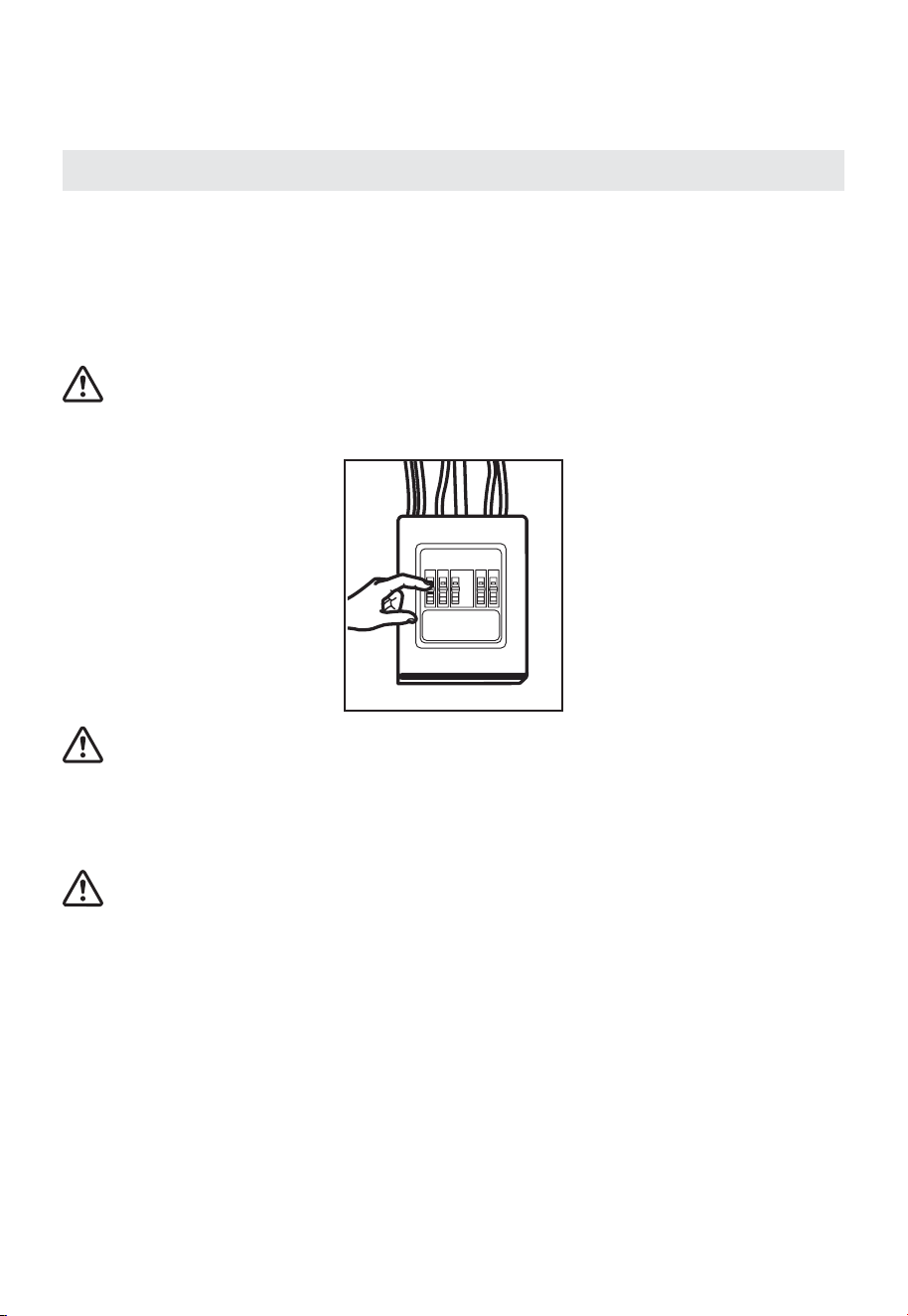
Cleaning the cooking compartment and putting the turntable in place. For new
installations, make sure all packaging and shipping tape has been removed from
the turntable shaft. Before using the appliance to prepare food for the first time,
you will need to put the turntable in place correctly. You must clean the cooking
compartment and accessories.
3
2
1
How to put the turntable in place:
1. Place the turntable ring assembly
③
into
the recess in the cooking compartment.
2. Place the glass tray
①
on the turntable
ring assembly
③
. Fit the raised, curved
lines in the center of the glass tray
bottom between the three spokes of the
shaft. Make sure that the glass tray
①
engages in the turntable shaft
②
in the
centre of the cooking compartment floor.
The rollers on the shaft should fit inside
the turntable bottom ridge.
Notes:
1. Never use the appliance without the turntable. Make sure that it is properly
engaged. The turntable can turn clockwise or anti-clockwise.
2. Never place the glass tray upside down. The glass tray should never be
restricted.
3. Both glass tray and turntable ring assembly must always be used during
cooking.
4. All food and containers of food are always placed on the glass tray for cooking.
5. Never restrict the movement of the turntable.
6. If glass tray or turntable ring assembly cracks or breaks, contact your nearest
authorized service center.
16
PRODUCT INSTALLATION
Important Safety Instructions
This product requires a three-prong grounded outlet.
The installer must perform a ground continuity check on the power outlet box before
beginning the installation to ensure that the outlet box is properly grounded.
If not properly grounded, or if the outlet box does not meet electrical requirements (noted
under ELECTRICAL REQUIREMENTS), a qualified electrician should be employed to
correct any deficiencies.
CAUTION:
For personal safety, remove house fuse or flip the breaker to the off position before
beginning installation to avoid severe injury or fatal shock.
CAUTION:
For personal safety, the mounting surface must be capable of supporting a total weight
of 113–135 pounds (51.3–61.2 kg). This contains the cabinet load, the added weight of
this 63–85 pound (28.5–38.5 kg) product, and additional oven loads of up to 50 pounds
(22.7 kg).
CAUTION:
For personal safety, this product cannot be installed in cabinet arrangements such as
an island or a peninsula. It must be mounted to BOTH a top cabinet AND a wall.
IMPORTANT – PLEASE READ CAREFULLY. FOR PERSONAL SAFETY, THIS APPLIANCE
MUST BE PROPERLY GROUNDED TO AVOID SEVERE OR FATAL SHOCK.
17
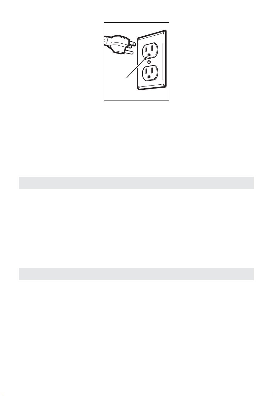
Ensure proper
ground exists
before use
The power cord of this appliance is equipped with a three-prong (grounding) plug which
mates with a standard three-prong (grounding) wall outlet to minimize the possibility of
electric shock from this appliance.
You should have the wall outlet and circuit checked by a qualified electrician to make
sure the outlet is properly grounded.
If you have a standard two-prong wall outlet, it is very important to have it replaced
with a properly grounded three-prong wall outlet, installed by a qualified electrician. DO
NOT, UNDER ANY CIRCUMSTANCES, CUT, DEFORM OR REMOVE ANY OF THE PRONGS
FROM THE POWERCORD. DO NOT USE WITH AN EXTENSION CORD.
Electrical Requirements
This product is rated for a 120 Volt AC, 60 Hertz, 13 5 amp and 1.55. Kilowatt connection.
This product must be connected to a separate and dedicated supply power supply with
the correct voltage and frequency. The wire size must conform to the requirements of
the National Electrical Code or the prevailing local code for this kilowatt rating. The
power supply cord and plug should be run to a separate and dedicated 15- to 20- ampere
branch circuit single grounded outlet. The outlet box should be located in the cabinet
above the microwave oven. The outlet box and supply circuit should be installed by a
qualifed electrician and conform to the National Electrical Code or the prevailing local
code.
Damage—Shipment/Installation
1. If the unit is damaged in shipment, return the unit to the store in which it was bought
for repair or replacement.
2. If the unit is damaged by the customer, repair or replacement is the responsibility of
the customer.
3. If the unit is damaged by the installer (if other than the customer), repair or
replacement must be made by arrangement between customer and installer.
18
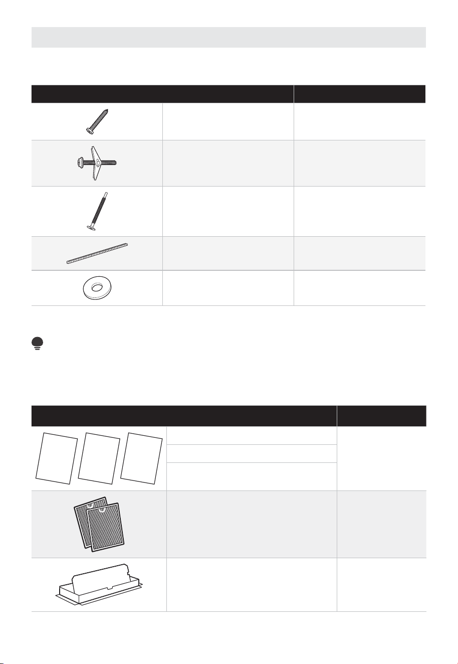
Parts Included
HARDWARE PACKET
PART QUANTITY
Wood Screws
( ⁄
4
” x 2”)
2
Toggle Bolts (and wing nuts)
(
3
⁄
16
” x 3”)
4
Self-Aligning Machine
Screws
(
1
⁄
4
”-28 x 3
1
⁄
4
”)
3
Nylon Grommet
(for metal cabinets)
2
Shim
6
You will find the installation hardware contained in a packet with the unit. Check to make
sure you have all these parts.
NOTE:
Some extra parts are included.
ADDITIONAL PARTS
PART QUANTITY
UCTIONSI
INST
NSTR
ALLATION
U
S
E
&
C
A
R
E
M
A
N
U
A
L
kciuQ ediuG
I
n
s
t
a
l
l
a
t
i
o
n
Installation Instructions
1
Use & Care Manual
Installation Quick Guide
Separately Packed Grease Filters 2
Exhaust adaptor 1
1
19
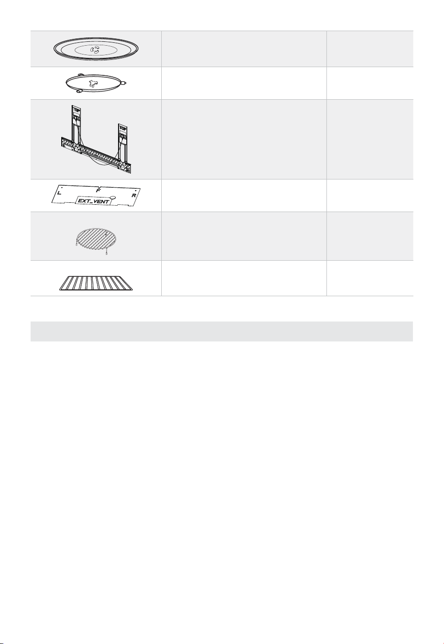
Glass Tray 1
Turntable Ring 1
Install Components 1
Top Cabinet Mounting Template 1
For some models
Convection wire rack 1
For some models
Shelf 1
Tools You Will Need
• Tape measure
• Hole saw
• Stud finder
• Level
• Duct and masking tape
• Scissors
• #1 Phillips screw driver
• Electric drill
• 3/16”, 1/2”, 5/8” drill bit
• Filler wood blocks for recessed bottom cabinets
• Tin snips
20
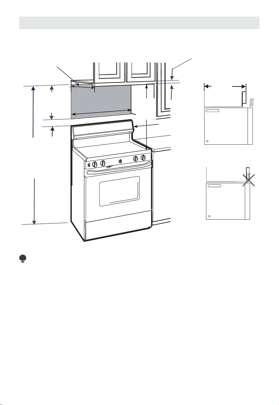
Mounting Space
MOUNTING SPACE
66”
(167.6 cm)
or more from the
floor to the top
of the microwave
13” Max
(33 cm)
30”
(76.2 cm)
min.
2” (5.1 cm)
30” (76.2 cm)
13” Max
(33 cm)
1
/
4
” Min
Clearance
Backsplash
Cabinet
Cabinet
16
1
/
2
”
(41.9 cm)
NOTE:
• The space between the cabinets must be 30” (76.2 cm) wide and free of obstructions.
• If you are going to vent your microwave oven to the outside, see the Hood Exhaust
section to prepare the exhaust duct.
• When installing the microwave oven beneath smooth, flat cabinets, be careful to
follow the instructions on the top cabinet template for power cord clearance.
• See the next page for a guide to placing the mounting plate.
• If the cabinet depth, including the cabinet doors, is more than 13”, then the unit must
be spaced out from the wall using materials that support at least 150 lbs to allow
proper top vent air exhaust/intake.
21
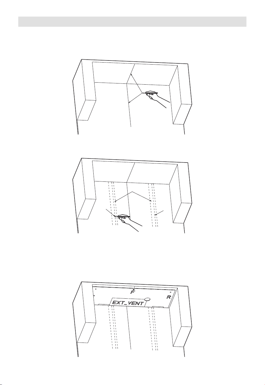
1. Mounting Plate Placement
A. Measure the width of the installation area on the rear wall, then locate the center
point of the installation area’s width. Using a level or plumb line, draw a vertical
centerline through this point to mark the center on both the rear wall and the
bottom of the top cabinet.
CENTERLINE
B. Use a stud finder to locate the center of each wall stud. Depending on the installation
area, there may be 1 or 2. When a stud is found, mark both the left and right edges of
the stud, then draw a centerline between the two marks.
CENTERLINE
WALL
STUDS
CENTERLINE
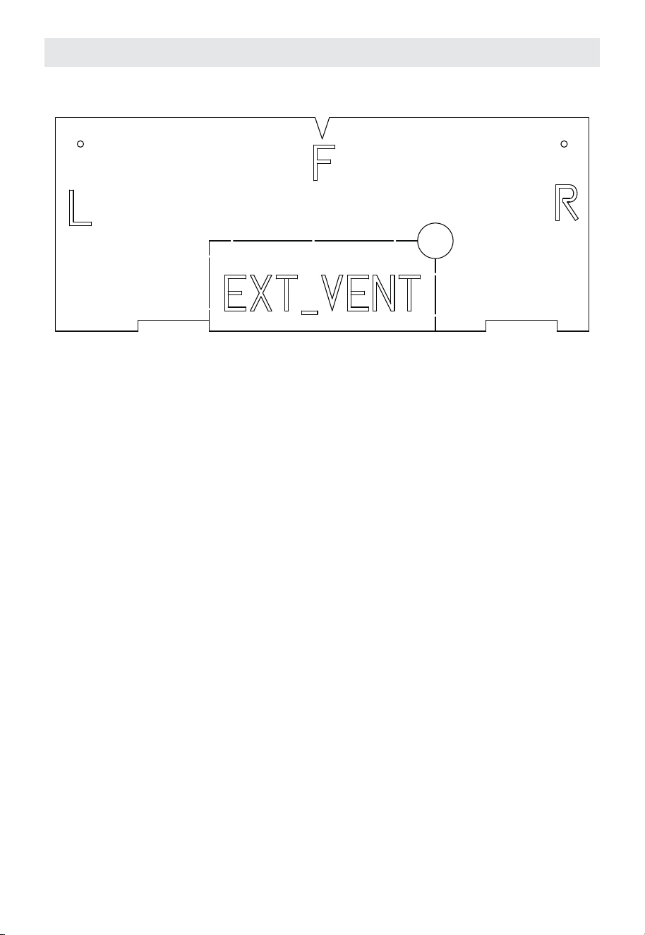
C. Open the package and take out the Top Cabinet Mounting Template (acardboard
template). Align the markings “F” (Front), “L” (Left), “R” (Right), and “EXT_VENT”
with the corresponding sides of the cabinet the “FRONT”, “Left”, “Right”, and
exterior vent (EXT_VENT). Place the rear edge of the template flush against the
wall, make sure the front notch aligns with the centerline, and lay it flat against
the bottom of the cabinet. Once aligned, keep the template pressed against the
cabinet.
22
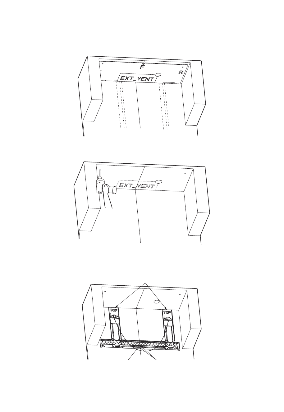
D. Using the holes on the cardboard Top Cabinet Mounting Template, mark two small
circles and one large circle on the bottom of the cabinet with a pencil. Keep the
pencil vertical while marking. If top exhaust vent installation is required, tear out
the “EXT_VENT” section on the template and trace its outline onto the cabinet,
then remove the template.
E. Drill two 5/8” holes through the cabinet at the two small circle marks, and one 2”
hole at the large circle mark. If installing the top exhaust vent, cut out the vent
opening by following the “EXT_VENT” outline.
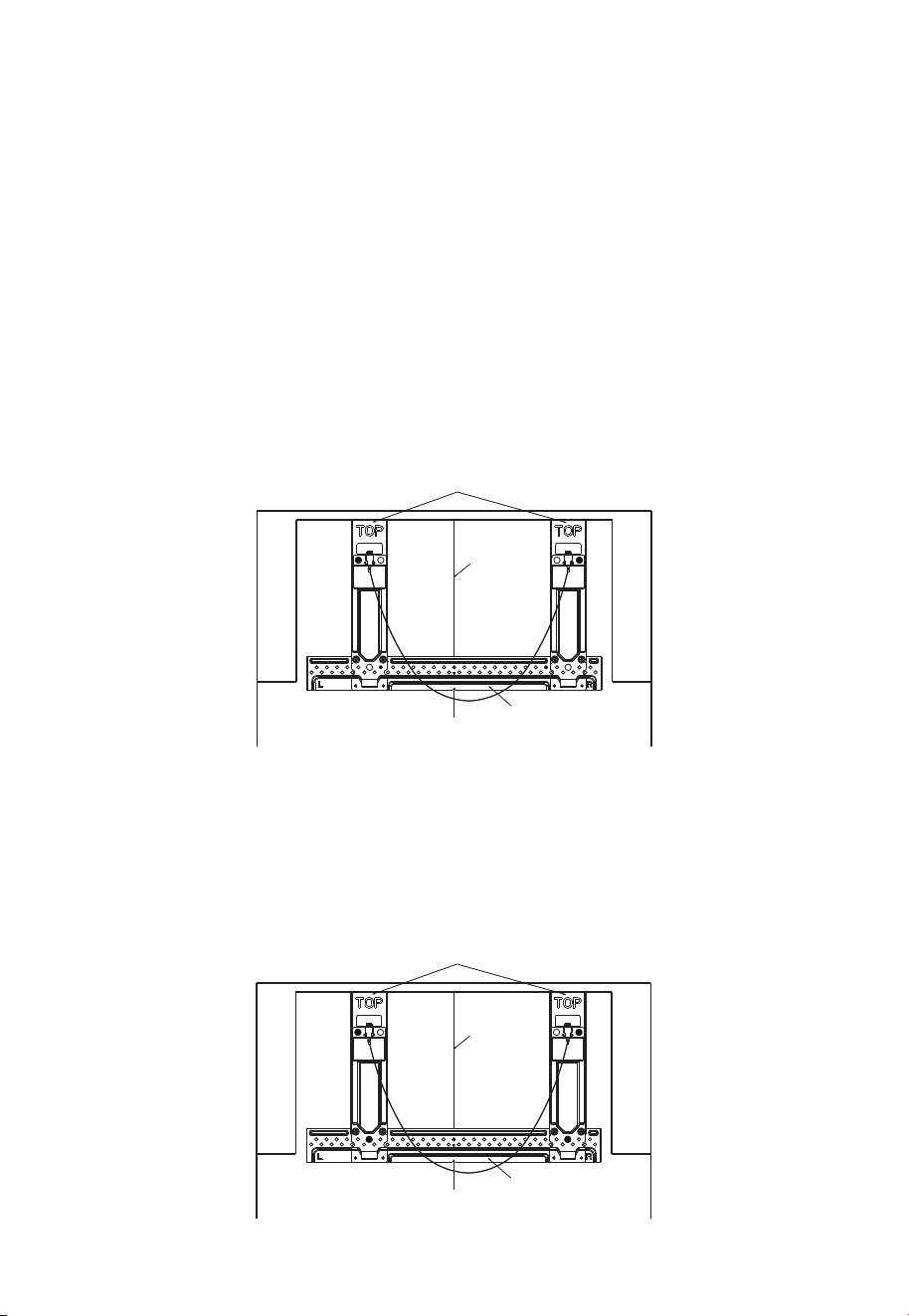
F. Place the mounting bracket against the rear wall. Make sure the top edge of the
bracket is flush with the bottom of the cabinet or cabinet lip. Align the tip of the
triangle center mark on the bracket with the installation area centerline drawn on
the wall. Ensure the pull cord is facing outward.
Flush with the bottom of the cabinet or cabinet lip
The pull cord faces outward The tip of the triangle is
aligned with the center
23
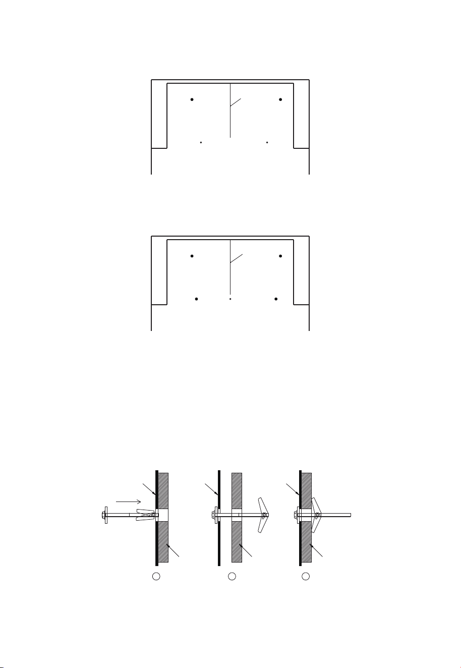
G. Mark the Drill Hole Locations
Use the holes on the mounting bracket to mark the drill hole locations. The hole
locations will differ based on how many wall studs the bracket covers.
Case 1 (if the bracket covers two wall studs) will require four drill holes. Refer to steps
G1 and H1 for more information.
Case 2 (if the bracket covers only one wall stud) will require five drill holes. Refer to
steps G2 and H2 for more information.
G1. Mark the Drill Hole Locations (Case 1: The bracket spans across two wall studs) —
mark 4 holes in total.
1. Support Holes (for wood screws): On the bottom horizontal bar of the bracket, locate
the two small holes that are closest to the centerlines of the studs and mark their
positions on the wall.
2. Stabilizing Holes (for butterfly screws): On each vertical arm of the bracket, find one
large hole that does not overlap with a stud and mark its position on the wall.˜Only
one mounting hole per vertical arm is required.
CENTERLINE
Horizontal Bar
Vertical Arms
G2. Mark the Drill Hole Locations (Case 2: The bracket covers only one wall stud) —
mark 5 holes in total.
1. Support Hole (for wood screw): On the bottom horizontal bar of the bracket, locate
the small hole that is closest to the centerline of the stud and mark its position on the
wall.
2. Stabilizing Holes (for butterfly screws): Mark one large hole on each upper vertical
arm, and one large hole at the intersection of the bottom horizontal bar and each
vertical arm.
CENTERLINE
Horizontal Bar
Vertical Arms
24
H.
H1. Remove the Mounting Bracket (Case 1)
Drill through the small marked holes using a 3/16” drill bit and drill through the
large marked holes using a 5/8” drill bit.
CENTERLINE
H2. Remove the Mounting Bracket (Case 2)
Drill through the small marked holes using a 3/16” drill bit and drill through the
large marked holes using a 5/8” drill bit.
CENTERLINE
I. Assemble and Mount the Bracket
1. Insert each toggle bolt into the center hole of a shim, then the center of a wing nut
to create a toggle bolt assembly. Create a toggle bottle assembly for each large
hole.˜Reposition the mounting bracket on the wall as described in Step F.
2. First, secure the bracket to the small holes using the wood screws.
3. Then, insert the toggle wing side of the toggle bolt assemblies through the large holes,
then pull the toggle bolts back gently to ensure the toggle wings are fully opened and
cannot be pulled out — this indicates proper anchoring.
4. Finally, tighten all screws firmly.
1 32
Mounting
Bracket
Mounting
Bracket
Mounting
Bracket
WALL WALL WALL
Toggle Bolt Assembly Installation
25
2. Installation Types (Choose A, B or C)
This microwave oven is designed for adaptation to the following three types of
ventilation:
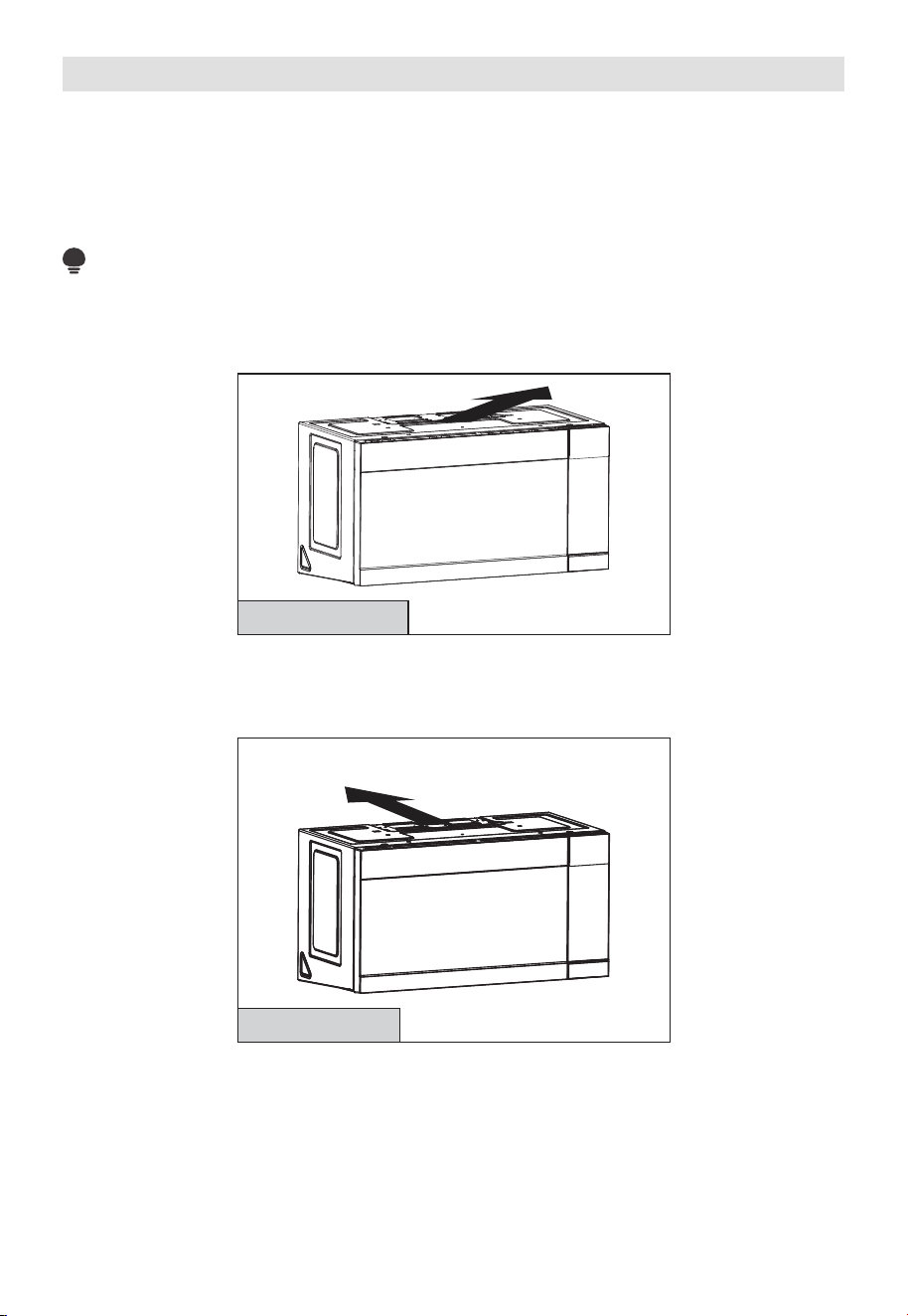
A. Outside Top Exhaust (Vertical Duct)
B. Outside Back Exhaust (Horizontal Duct)
C. Recirculating (Non-Vented Ductless)
NOTE:
Read pages 31-33 only if you plan to vent your exhaust to the outside. If you plan
to recirculate the air back into the room, proceed to page 26.
A. RECIRCULATING (NON-
VENTED DUCTLESS)
See page 26
Models are shipped for recirculating exhaust. Some models have a disposable charcoal
filter installed to help remove smoke and odors.
B. OUTSIDE BACK EXHAUST (HORIZONTAL DUCT)
Adapt or Must Be
Moved to the Back for
Outside Back Exhaust
See page 33
26
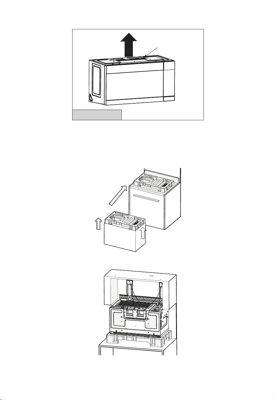
C. OUTSIDE TOP EXHAUST (VERTICAL DUCT)
Adaptor in Place for
Outside Top Exhaust
See page 38
A. RECIRCULATING (Non-Vented Ductless)
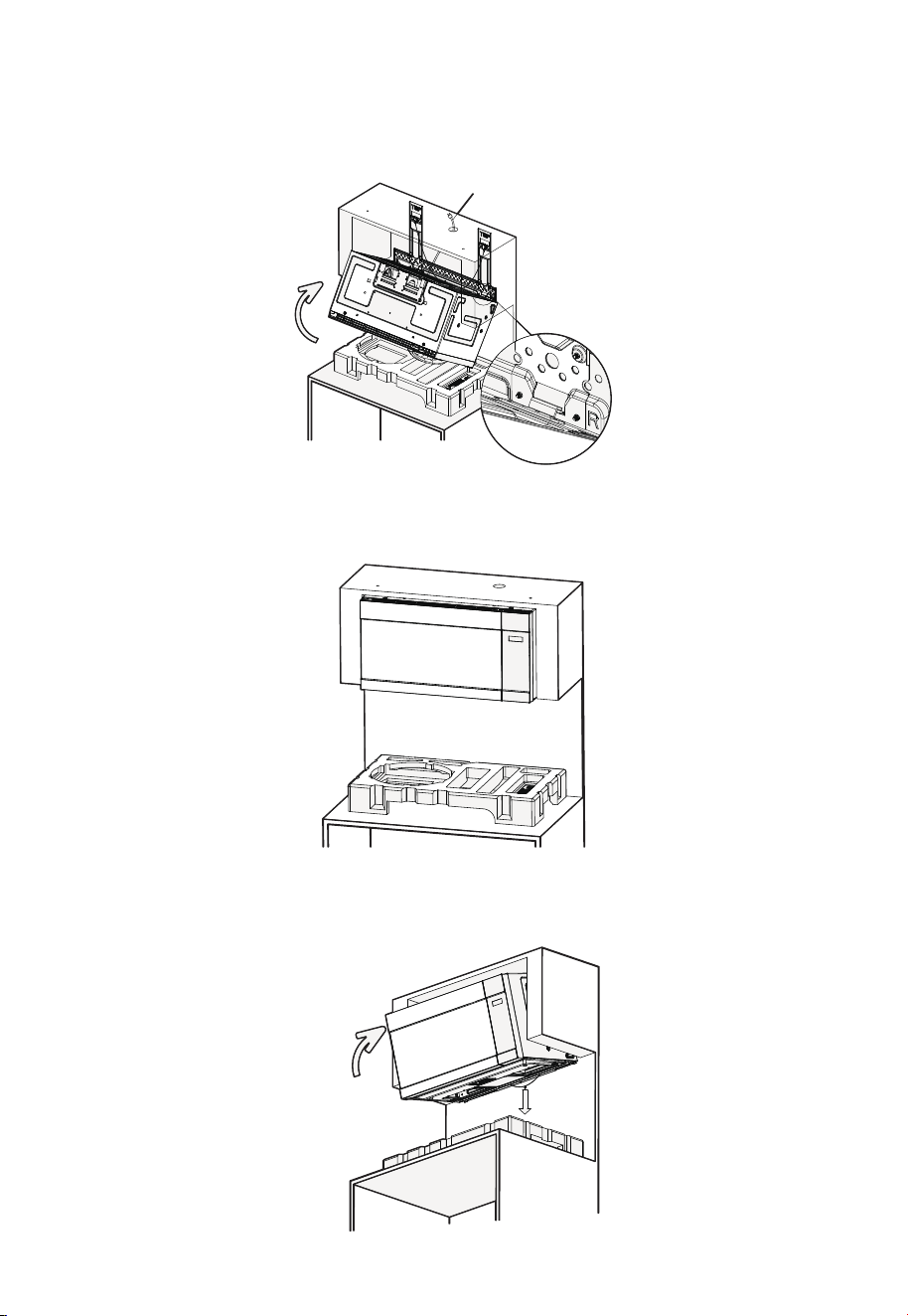
A1. MOUNT THE MICROWAVE OVEN
1. Remove the top foam block from the carton and place it on the range as shown in the
illustration.
Make sure the large round hole on the foam is positioned on the left side.
2. Place the microwave oven on the foam block as shown in the illustration, with the back
facing up and the door facing down.
27
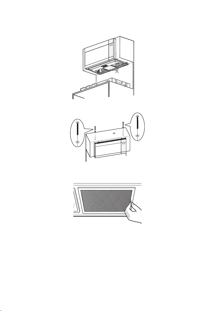
3. Lift the microwave oven and make sure the rear mounting tabs on the microwave fit
securely into the bracket slots (see enlarged detail view). While supporting the front
of the microwave door, rotate the unit upward over the bracket, and at the same time
feed the power cord completely through the power cord hole in the top cabinet.
Tighten the power cord
Bracket slots
4. Firmly push the microwave upward, toward the wall, until you hear a “click” sound,
indicating it is securely latched onto the bracket. Then slowly release your support
hand to make sure the unit is properly fixed in place.
5. If the microwave is not securely latched (unit does not stay in place without the
support of your hand), pull down the release cord on the mounting bracket while
firmly pushing the microwave toward the wall. Then release the cord and slowly let go
of the microwave, ensuring it is securely locked in place.
Push firmly
Pull down
28
6. After the microwave is securely installed, ensure the release cord hangs naturally in
its relaxed position. The release cord is for installation and removal only — do not pull
it at any other time, as this may cause the microwave to fall and result in injury or
damage.
Do not pull down!
7. Insert the two top screws through the shims, then tighten both top screws securely.
8. Install the grease filters.
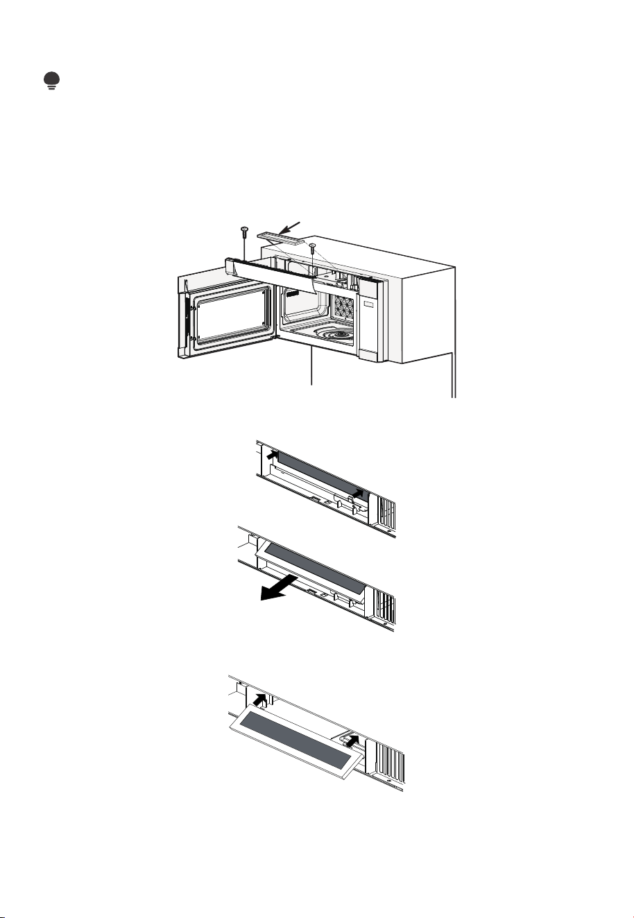
29
A2. CHARCOAL FILTER REPLACEMENT
NOTE:
Charcoal Filter when installed in your microwave oven, is used for nonvented, recirculated
installation. The filter should be changed every 6 to 12 months depending on use.
1. Unplug the microwave oven or disconnect power.
2. Open the microwave door and remove the two vent mounting screws located on top
of the microwave using a #1 Phillips screwdriver.
Charcoal
Filter
3. Remove the charcoal filter by pushing the top of the filter inwards, then pulling it
forward and out from the unit.
4. Slide the top of the new charcoal filter into the top of the filter cavity.
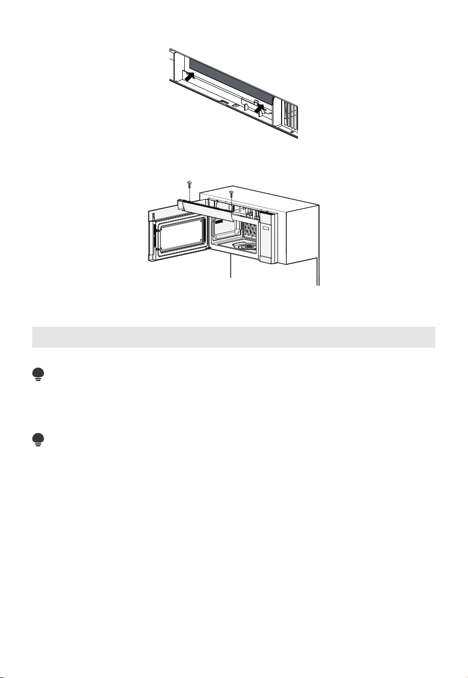
30
5. Press the bottom of charcoal filter inwards to place it into the correct position.
6. Reinstall the vent by sliding the bottom of the vent into place. Push the vent top into
position and slide right into place. Replace the two vent mounting screws located on
top of the microwave using a #1 Phillips screwdriver.
7. Close the microwave door. Plug in the microwave oven or reconnect power.
Installation Instructions For External Exhaust Ducting
NOTE:
If you need to install ducts, note that the total duct length of 31/4” x 10” (8.2 x 25.4 cm)
rectangular or 5” (12.7 cm) diameter/ 6” (15.2 cm) diameter round duct should not exceed
140 equivalent feet (42.7 m).
Outside ventilation requires an EXTERNAL EXHAUST DUCT. Read the following carefully.
NOTE:
It is important that venting be installed using the most direct route and with as few
elbows as possible. This ensures clear venting of exhaust and helps prevent blockages.
Also, make sure dampers swing freely and nothing is blocking the ducts.
Exhaust connection:
The exhaust adaptor has been designed to mate with a standard 3 1/4” x 10” (8.2 x 25.4
cm) rectangular duct.
If a round duct is required, a rectangular-to-round transition adaptor must be used. A 5”
(12.7cm)/ 6” (15.2cm) diameter duct is acceptable to use.
Maximum duct length:
For satisfactory air movement, the total duct length of 3 1/4” x 10” (8.2 x 25.4 cm)
rectangular or 5” (12.7 cm) diameter/ 6” (15.2 cm) diameter round duct should not exceed
140 equivalent feet (42.7 m).
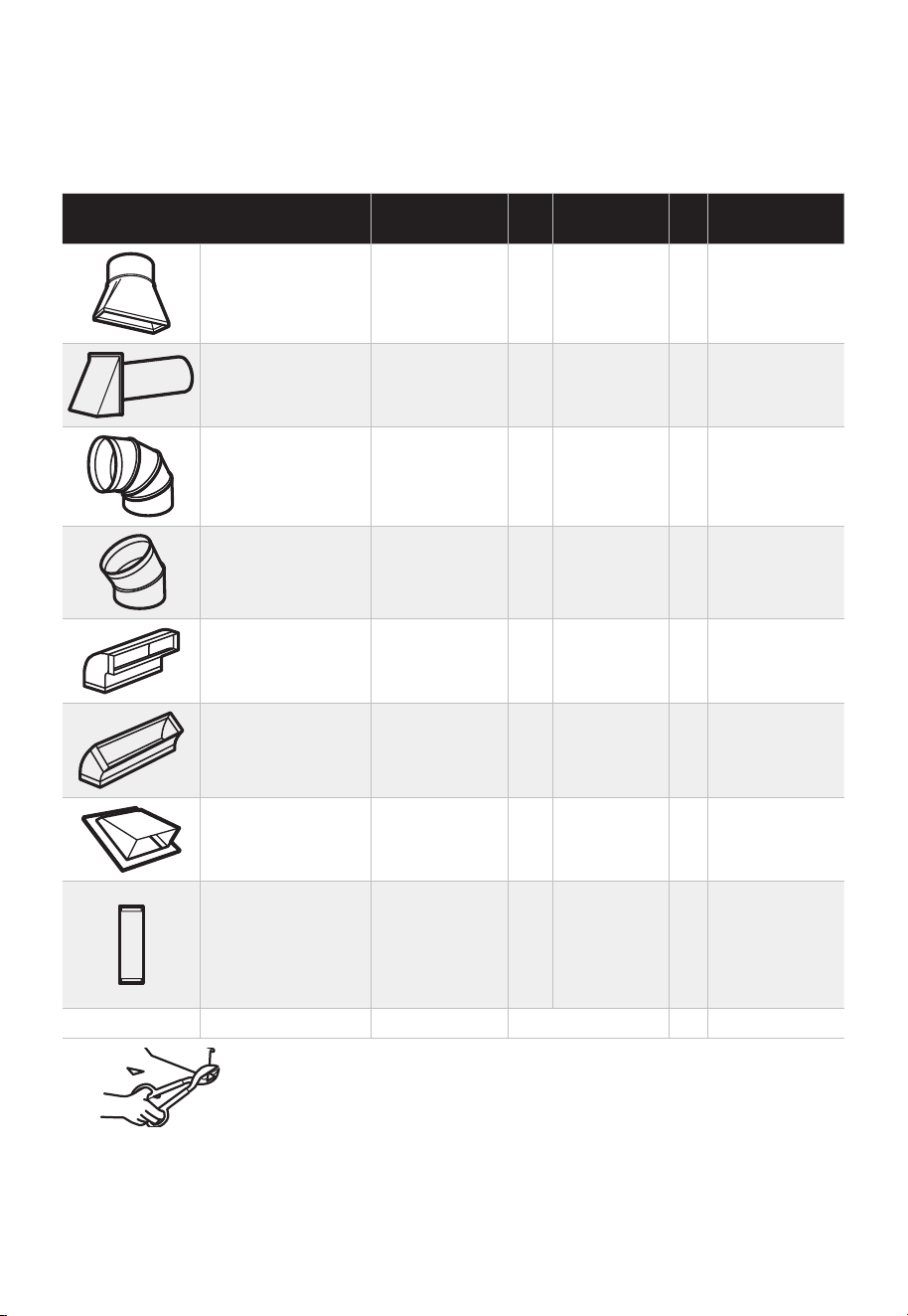
31
Elbows, transitions, wall and roof caps, etc., present additional resistance to airflow and
are more resistant than a straight duct of equivalent length. When calculating the total
duct length, add the equivalent lengths of all transitions and adaptors plus the length of
all straight duct sections. The chart below shows you how to calculate total equivalent
ductwork length using the equivalent length in approximate feet of some typical ducts.
DUCT PIECES
EQUIVALENT
LENGTH
x
NUMBER
USED
=
EQUIVALENT
LENGTH
Rectangular-to-
Round Transition
Adaptor*
5 Ft. (1.5 m) x ( ) = Ft. or m
Wall Cap 40 Ft. (12.2 m) x ( ) = Ft. or m
90° Elbow 10 Ft. (3 m) x ( ) = Ft. or m
45° Elbow 5 Ft. (1.5 m) x ( ) = Ft. or m
90° Elbow 25 Ft. (7.6 m) x ( ) = Ft. or m
45° Elbow 5 Ft. (1.5 m) x ( ) = Ft. or m
Roof Cap 24 Ft. (7.3 m) x ( ) = Ft. or m
Straight Duct 6”
(15.2 cm) Round
or
1
/
4
” x 10”
(8.2 x 25.4 cm
Rectangular)
1 Ft. (0.3 m) x ( ) = Ft. or m
Total Ductwork = Ft. or m
* IMPORTANT: If a rectangular-to-round transition adaptor is used,
the bottom corners of the damper will have to be cut to fit, using
the tin snips, in order to allow free movement of the damper.
Equivalent lengths of duct pieces are based on actual tests and reflect requirements for
good venting performance with any vent hood.
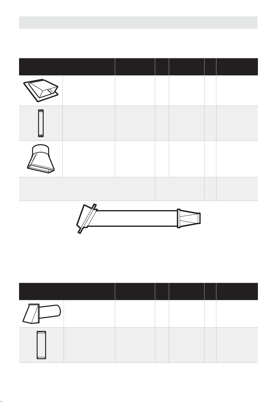
32
External Exhaust Ducting
OUTSIDE TOP EXHAUST (EXAMPLE ONLY)
The following chart describes an example of one possible ductwork installation.
DUCT PIECES
EQUIVALENT
LENGTH
x
NUMBER
USED
=
EQUIVALENT
LENGTH
Roof Cap 24 Ft. (7.3 m) x (1) = 24 Ft. (7.3 m)
12 Ft. (3.6 m)
Straight Duct
(6”/15.2 cm
Round)
12 Ft. (3.6 m) x (1) = 12 Ft. (3.6 m)
Rectangular-to-
Round Transition
Adaptor*
5 Ft. (1.5 m) x (1) = 5 Ft. (1.5 m)
Equivalent lengths of duct pieces are based on
actual tests and reflect requirements for good
venting performance with any vent hood.
Total Length = 41 Ft. (12.5 m)
* IMPORTANT: If a rectangular-to-round transition adaptor is used, the bottom corners of
the damper will have to be cut to fit, using the tin snips, in order to allow free movement
of the damper.
OUTSIDE BACK EXHAUST (EXAMPLE ONLY)
The following chart describes an example of one possible ductwork installation.
DUCT PIECES
EQUIVALENT
LENGTH
x
NUMBER
USED
=
EQUIVALENT
LENGTH
Wall Cap 40 Ft. (12.2 m) x (1) = 40 Ft. (12.2 m)
3 Ft. Straight
Duct (3
1
⁄
4
”x
10”/8.2 x 25.4 cm
Rectangular)
3 Ft. (0.9 m) x (1) = 3 Ft. (0.9 m)
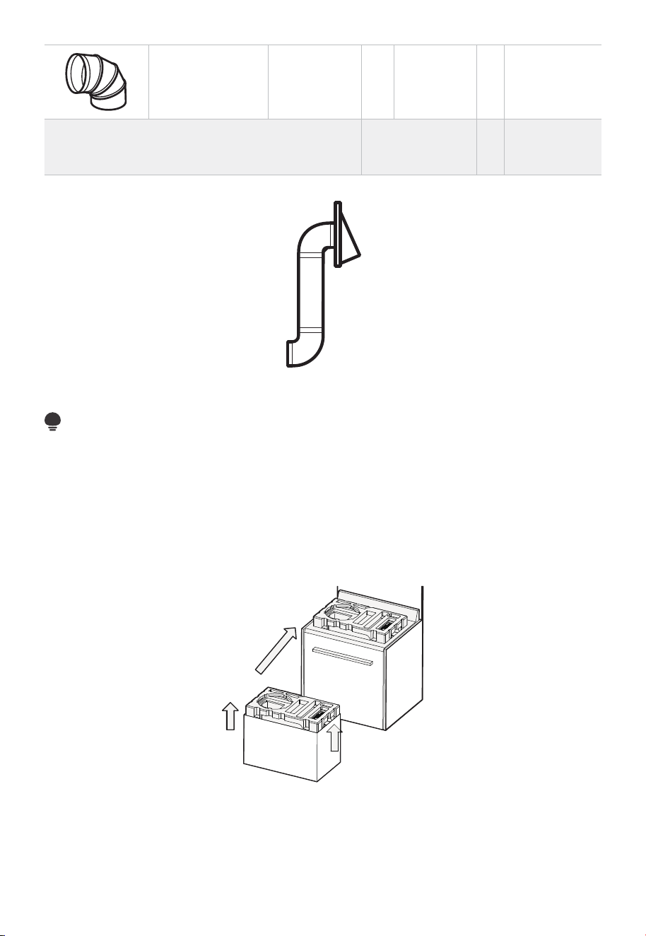
33
90° Elbow 10 Ft. (3 m) x (2) = 20 Ft. (3 m)
Equivalent lengths of duct pieces are based on
actual tests and reflect requirements for good
venting performance with any vent hood.
Total Length = 63 Ft. (19.2 m)
NOTE:
For back exhaust, care should be taken to align exhaust with space between studs, or
wall should be prepared at the time it is constructed by leaving enough space between
the wall studs to accommodate exhaust.
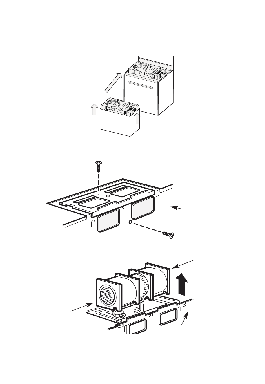
B. OUTSIDE TOP EXHAUST (Vertical Duct)
B1. ADAPT THE MICROWAVE BLOWER FOR OUTSIDE BACK EXHAUST
1. Remove the top foam block from the carton and place it on the range as shown in the
illustration.
Make sure the large round hole on the foam is positioned on the left side.
2. Remove the screws for the fan mounting plate and the microwave, as well as the
screws securing the fan to the microwave. Set the screws aside. Then, remove the fan
mounting plate.
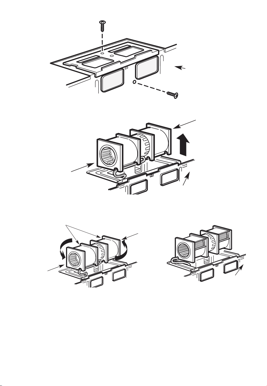
34
Back of
Microwave
3. Carefully pull out the fan. The wires will extend far enough to allow you to adjust the
fan.
Back of
Microwave
End B
End A
4. Rotate the fan 180°, as shown in the diagram.
Back of
Microwave
After Rolling
Before: Fan Blade
Openings Facing
Forward
End B
End A
5. Remove the knockout plates (some models only) in the back of the unit with snips.
Knockout Plates:
Snip all 4 webs on each knockout panel and remove the metal knockouts for rear
airflow. Please take care to remove any sharp edges created from removing the
knockout plates.
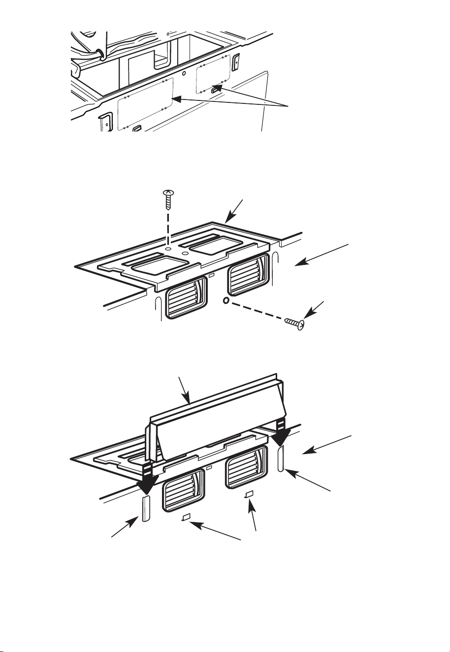
35
Back of microwave
6. Place the fan back into the unit, re-install the fan mounting plate, and tighten the
screws securing the microwave to the fan, as well as the screws securing the fan to the
mounting plate.
Blower Plate
Back of
Microwave
Blower Motor
Screw
7. Attach the exhaust adaptor to the rear of the oven by sliding it into the guides on the
oven back, adjacent to the fan mounting plate.
Back of
Microwave
Guide
Locking Tabs
Guide
Adaptor
36
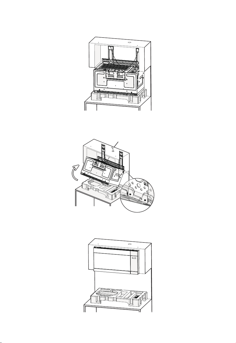
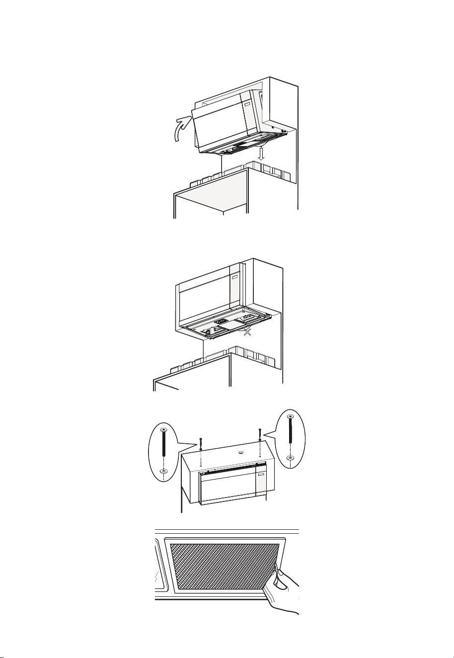
B2. MOUNT THE MICROWAVE OVEN
1. Place the microwave oven on the foam block as shown in the illustration, with the back
facing up and the door facing down.
2. Lift the microwave oven and make sure the rear mounting tabs on the microwave fit
securely into the bracket slots (see enlarged detail view). While supporting the front
of the microwave door, rotate the unit upward over the bracket, and at the same time
feed the power cord completely through the power cord hole in the top cabinet.
Tighten the power cord
Bracket slots
3. Firmly push the microwave upward toward the wall until you hear a “click” sound,
indicating it is securely latched onto the bracket. Then slowly release your support
hand to make sure the unit is properly fixed in place.
37
4. If the microwave is not securely latched (no “click” sound heard), pull down the
release cord on the mounting bracket while firmly pushing the microwave toward the
wall. Then release the cord and slowly let go of the microwave, ensuring it is securely
locked in place.
Push firmly
Pull down
5. After the microwave is securely installed, ensure the release cord hangs naturally in its
relaxed position. The release cord is for installation and removal only — do not pull it at
any other time, as this may cause the microwave to fall and result in injury or damage.
Do not pull down!
6. Insert the two top screws through the shims, and tighten both top screws securely.
7. Install grease filters.
38
C. OUTSIDE TOP EXHAUST (Vertical Duct)
C1. ADAPTING MICROWAVE BLOWER FOR OUTSIDE BACK EXHAUST
1. Remove the top foam block from the carton and place it on the range as shown in the
illustration.
Make sure the large round hole on the foam is positioned on the left side.
2. Remove the screws for the fan mounting plate and the microwave, as well as the
screws securing the fan to the microwave. Set the screws aside. Then, remove the fan
mounting plate.
Back of
Microwave
3. Carefully pull out the fan. The wires will extend far enough to allow you to adjust the
fan.
Back of
Microwave
End B
End A
39
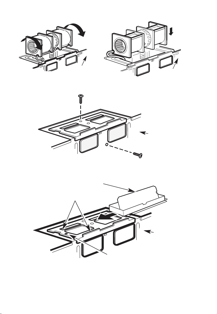
4. Rotate the fan 90° as shown in the illustration, then place the fan down.
Back of
Microwave
Back of
Microwave
5. Back into the unit, re-install the fan mounting plate, then tighten the screws securing
the microwave to the fan and the screws securing the fan to the mounting plate.
Back of
Microwave
6. Attach the exhaust adaptor to the top of the fan mounting plate by sliding it into the
guides of the fan mounting plate.
Back of
Microwave
Locking Tab
Guide
Adaptor
40
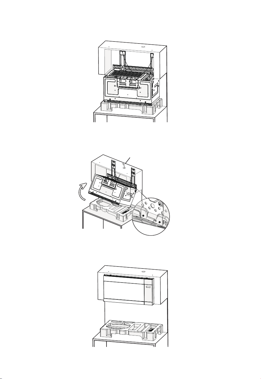
C2. MOUNT THE MICROWAVE OVEN
1. Place the microwave oven on the foam block as shown in the illustration, with the back
facing up and the door facing down.
2. Lift the microwave oven and make sure the rear mounting tabs on the microwave fit
securely into the bracket slots (see enlarged detail view).˜ While supporting the front
of the microwave door, rotate the unit upward over the bracket, and at the same time
feed the power cord completely through the power cord hole in the top cabinet.
Tighten the power cord
Bracket slots
3. Firmly push the microwave upward toward the wall until you hear a “click” sound,
indicating it is securely latched onto the bracket. Then slowly release your support
hand to make sure the unit is properly fixed in place.
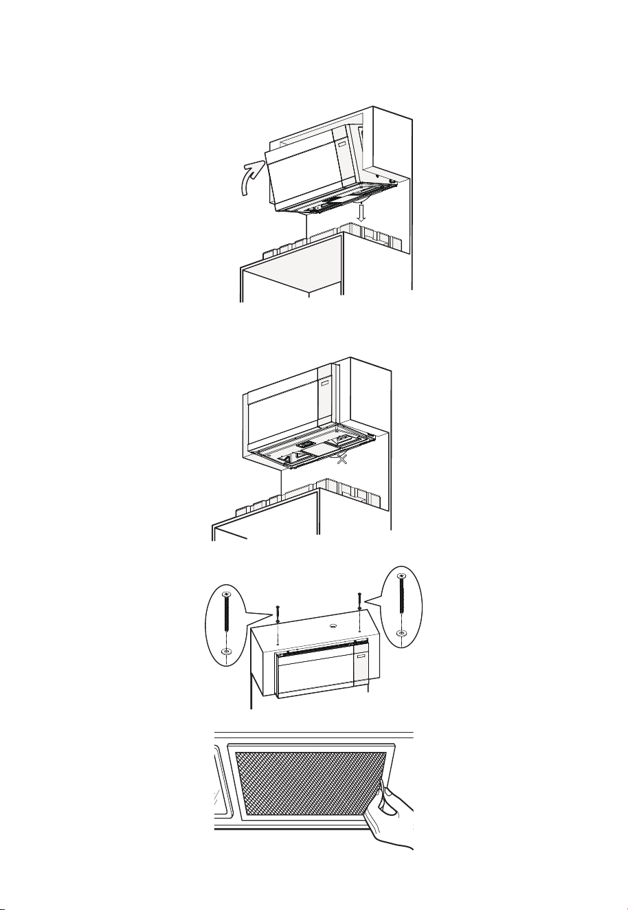
41
4. If the microwave is not securely latched (no “click” sound heard), pull down the
release cord on the mounting bracket while firmly pushing the microwave toward the
wall. Then release the cord and slowly let go of the microwave, ensuring it is securely
locked in place.
Push firmly
Pull down
5. After the microwave is securely installed, ensure the release cord hangs naturally in its
relaxed position. The release cord is for installation and removal only — do not pull it at
any other time, as this may cause the microwave to fall and result in injury or damage.
Do not pull down!
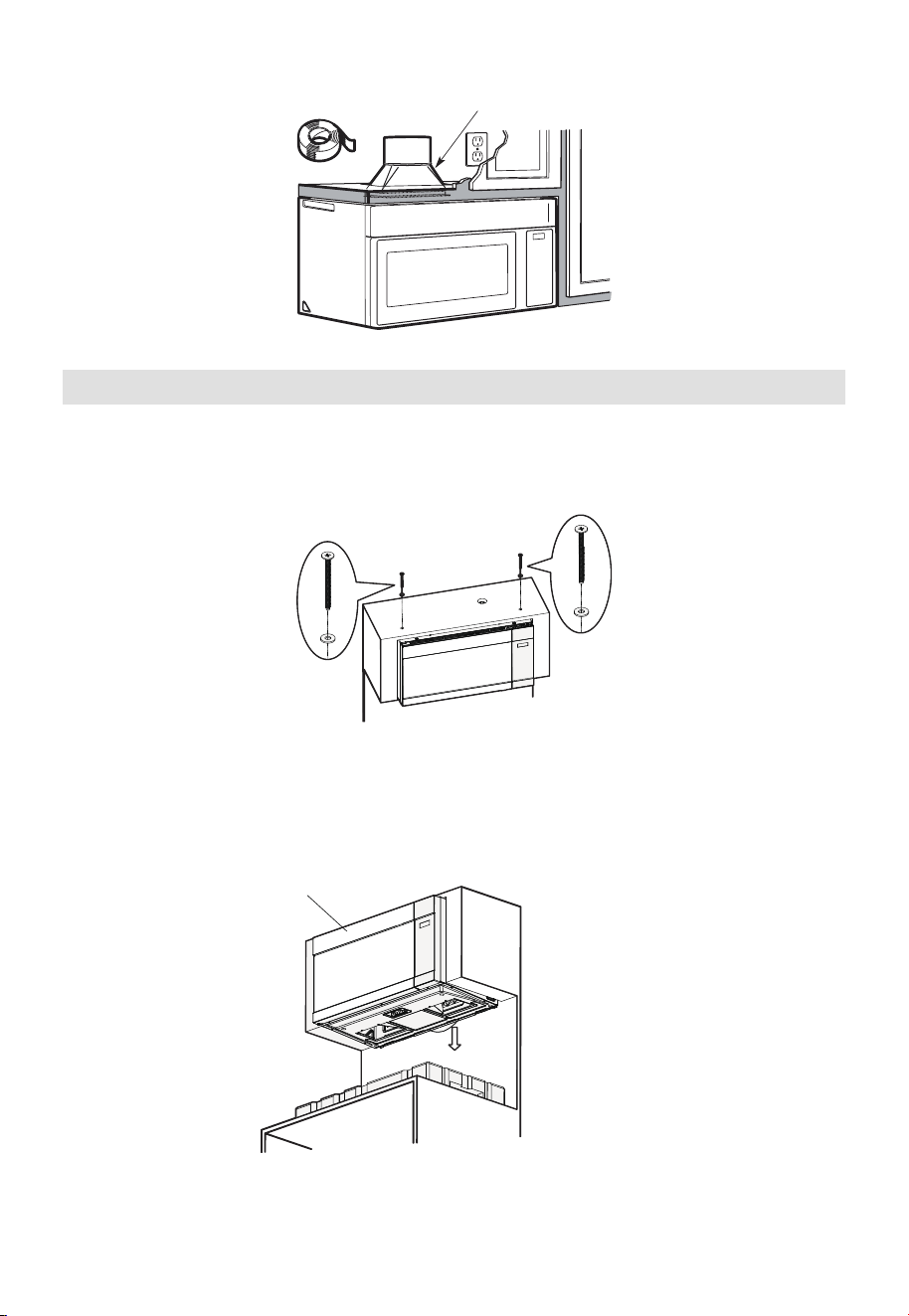
6. Insert the two top screws through the shims, and tighten both top screws securely.
7. Install grease filters.
42
8. Connect the vent duct to the top of the cabinet.
House Duct
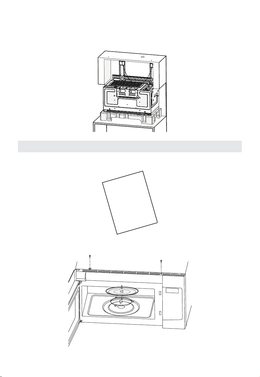
3. Microwave Oven Disassembly Method
If the microwave needs to be serviced or replaced later, follow the steps below:
A. Remove the bolts securing the top of the microwave to the cabinet. If necessary,
disconnect the upper vent duct.
B. Support the upper front edge of the microwave door with your hands. Then firmly
pull down the release cord located at the bottom of the microwave. The top of the
microwave will be released — do not let go of the microwave at this time.
1. Use your hand to hold the front
top of the microwave oven door
2. Pull down the release cord
43
C. At this point, slowly rotate the microwave downward and lower it to the surface to
complete the removal. Keep hold of the microwave so that it does not fall onto the
surface below. If you have the top foam block from the original packaging, you may
use it to cushion the microwave. If not, take care to gently lower it onto the surface
below.
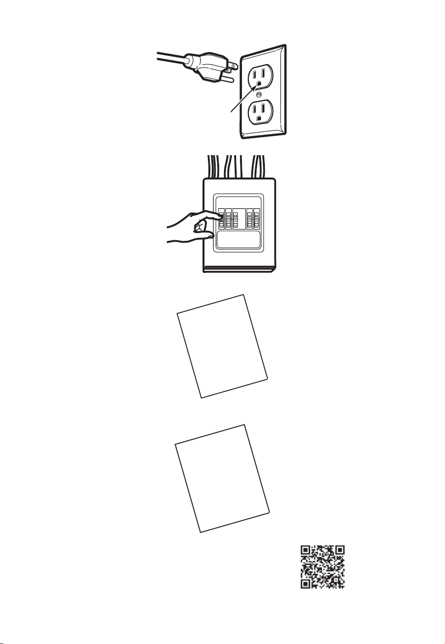
Before You Use Your Microwave
1. Make sure the microwave oven has been installed according to instructions.
INSTALLATION
INSTRUCTIONS
2. Remove all packing material from the microwave oven.
3. Install the turntable ring and glass tray in the microwave cavity.
44
4. Plug power cord into a seperate and dedicated 15- to 20-amp electrical outlet.
Ensure proper
ground exists
before use
5. Replace house fuse or turn breaker back on.
6. Read the USE & CARE Manual.
USE & CARE
MANUAL
7. KEEP INSTALLATION INSTRUCTIONS FOR THE LOCAL INSPECTOR’S USE.
INSTALLATION
INSTRUCTIONS
8. REGISTER YOUR PRODUCT ONLINE.
Registration on:
www.midea.com/us/support/Product-registration
US
45
Template Information
46
OPERATION
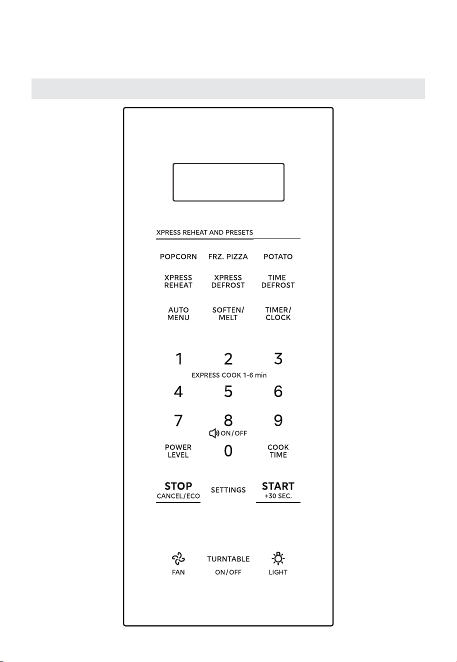
Control Panel
47
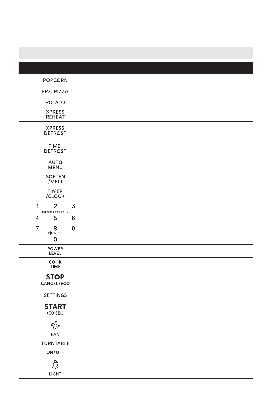
Button Function Overview
Button Description
Popcorn with preset programs by weight
Frozen pizza with preset programs by weight
Potato with preset programs by weight
Quickly reheat food based on the selected weight
Quickly defrost frozen foods based on the selected
weight
Quickly defrost frozen foods based on the selected
time
Auto menu with preset programs by weight
Soften or melt food based on the selected weight
Set the cooking timer / Set the clock
Use the number keys to enter customized values /
Press the numbers “1-6” to start speedy cooking for 1
to 6 minutes /
Use the number “8” to enter the mute mode setting
Set power level for microwave operation
Set cooking time for microwave operation
Pause active cooking status / Cancel current operation
/ Eco function
Set the user preference
Start speedy cooking for 30 seconds / Confirm input /
Start operation / Add 30 seconds
Set the vent high / low / off
Set the turntable on or off
Set the light on or off
OPERATION
48
OPERATION
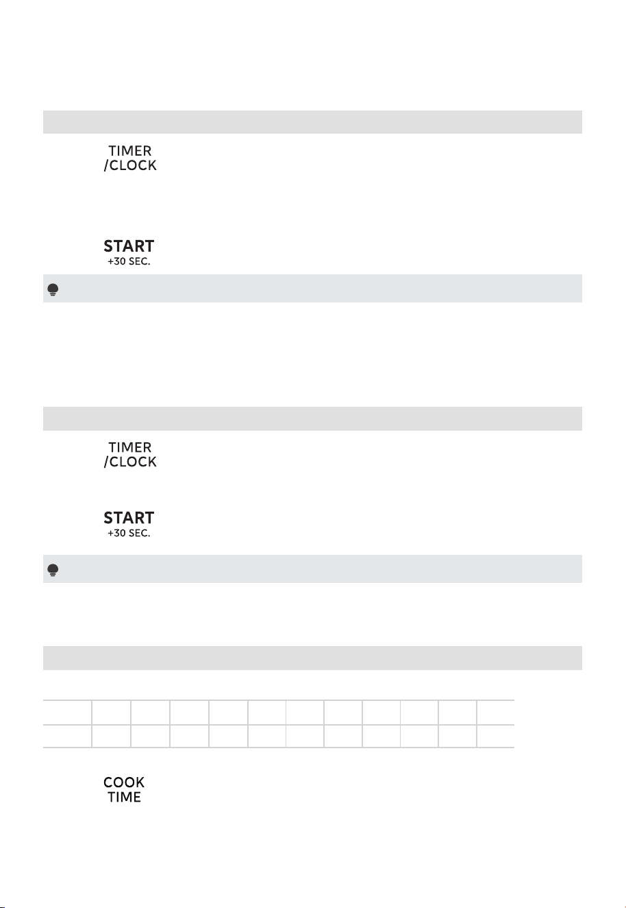
1. Setting the Clock
(1) Press twice, the clock or “12:00” will flash.
(Initial power-on, “12:00” will flash, please skip this step.)
(2) Press the number keys to enter the time.
Example: To set the clock to 12:10, please press “1, 2, 1, 0” in turn.
(3) Press to confirm. The clock is set.
Notes
(1) The clock is a 12-hour display. To reset the clock, please repeat step 1 to step 3.
(2) Upon initial power-up, if there is no operation within 5 minutes, the screen will
turn off.
2. Setting the Kitchen Timer
(1) Press once and then “:0” will display.
(2) Press the number keys to set the desired time. The maximum time value is
“99:99”.
(3) Press to confirm. The timer starts counting down.
Note
The kitchen timer is a timer.
3. Microwave Cooking
The 11 power levels are available.
Power 100% 90% 80% 70% 60% 50% 40% 30% 20% 10% 0%
Display P-HI P-90 P-80 P-70 P-60 P-50 P-40 P-30 P-20 P-10 P-0
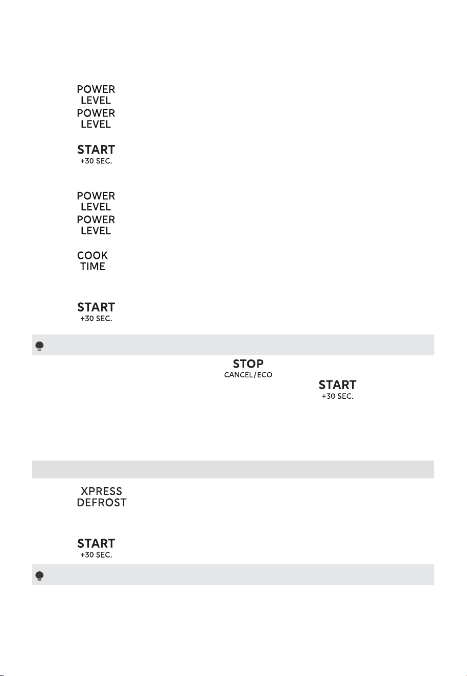
Method 1:
(1) Press once and then “:0” will display.
(2) Press the number keys to set the cooking time. The maximum time value is
“99:99”.
49
OPERATION
(3) Press once and then “P-HI” will display.
(4) Press repeatedly or press the number keys to set the power level. The
11 power levels are available.
(5) Press to start cooking.
Method 2:
(1) Press once and then “P-HI” will display.
(2) Press repeatedly or press the number keys to set the power level. The
11 power levels are available.
(3) Press once and then “:0” will display.
(4) Press the number keys to set the cooking time. The maximum time value is
“99:99”.
(5) Press to start cooking.
Notes
(1) Opening the oven door or pressing during operation will interrupt
the current mode. Close the oven door and then press to resume the
operation.
(2) If “P-0” is selected, the oven will work with a fan for no power. You can use
this level to remove the odor of the oven.
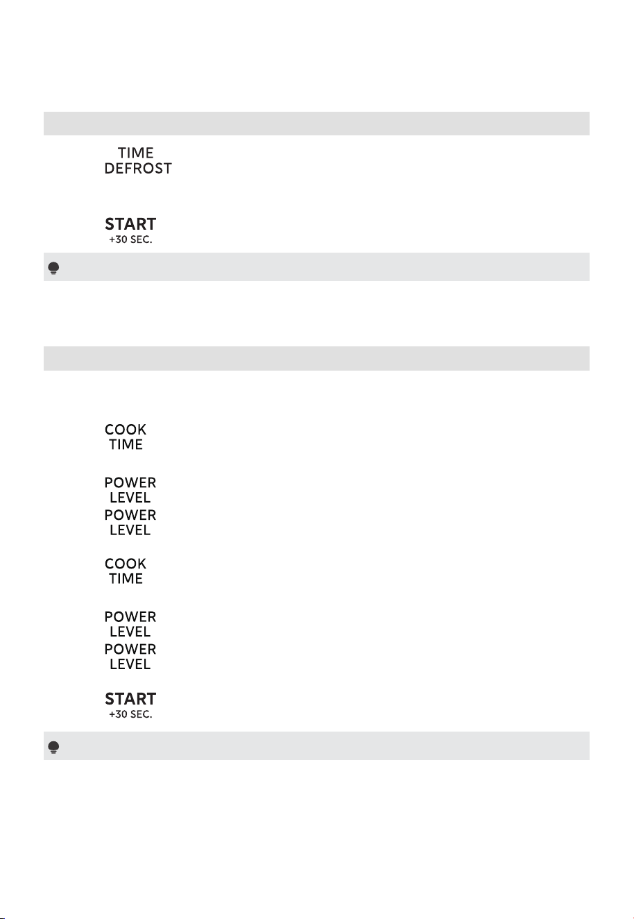
4. Xpress Defrost
(1) Press once and then “0.0 lb” will display.
(2) Press the number keys to set the weight of the food. The range of weight is
0.2~4.4lbs.
(3) Press to start defrosting.
Note
The buzzer will sound to remind you to turn the food over during defrosting. If
no operation, the oven will continue working.
50
OPERATION
5. Defrost by Time
(1) Press once and then “0:00” will display.
(2) Press the number keys to set the defrosting time. The maximum time value is
“99:99”.
(3) Press to start defrosting.
Note
The buzzer will sound to remind you to turn the food over during defrosting. If
no operation, the oven will continue working.
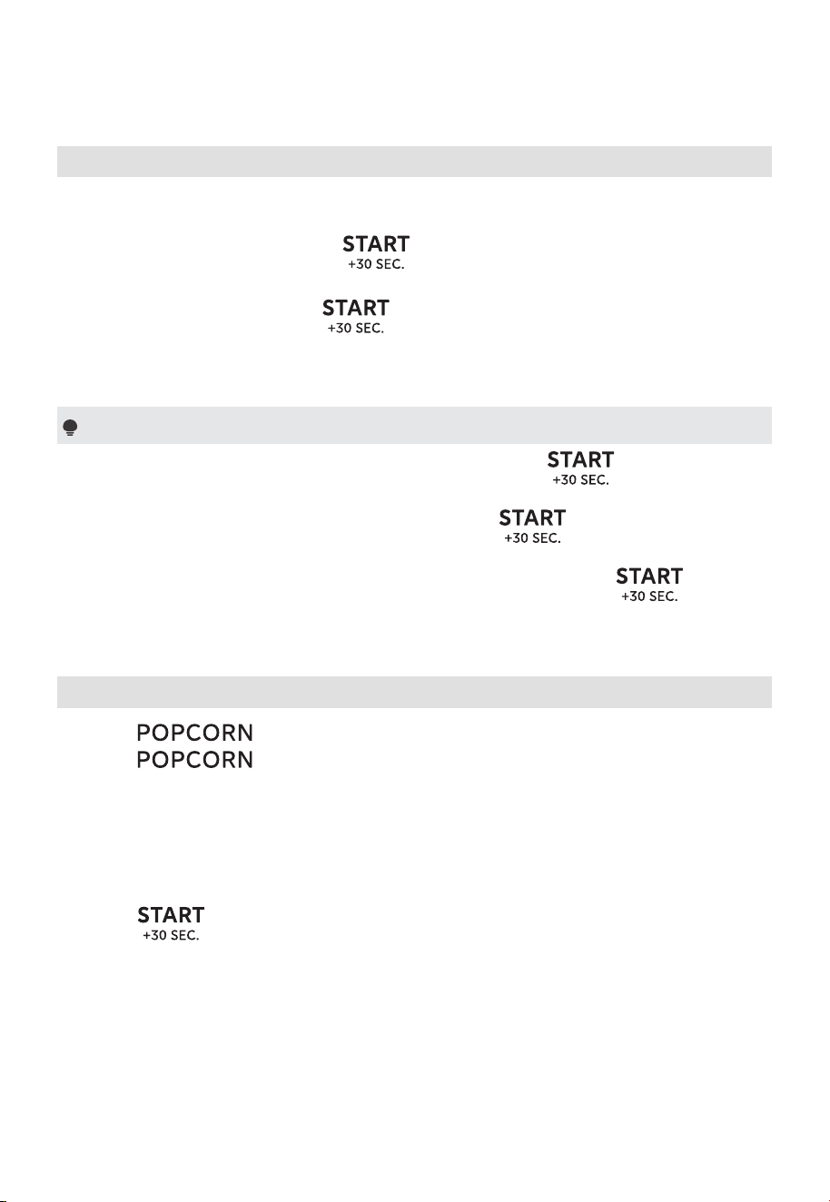
6. Multi-Stage Cooking
Example: Cook with 80% microwave power for 5 minutes and then cook with
50% microwave power for 7 minutes.
(1) Press once and then “ :0” will display.
(2) Press the number keys “5”, “0”, and “0” to set the cooking time to 5 minutes.
(3) Press once and then “P-HI” will display.
(4) Press repeatedly or press the number key “8” to set the power level
to “P-80”.
(5) Press once and then “ :0” will display.
(6) Press the number keys “7”, “0”, and “0” to set the cooking time to 7 minutes.
(7) Press once and then “P-HI” will display.
(8) Press repeatedly or press the number key “5” to set the power level
to “P-50”.
(9) Press to start cooking.
Note
(1) At most two stages of microwave cooking can be set.
(2) The second stage cooking setting method must match the first stage. If
cooking time is set first in the first stage, it must also be set first in the second
stage.
51
OPERATION
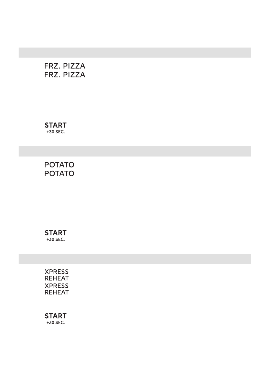
7. Speedy Cooking
(1) In standby mode, pressing the number keys 1 to 6 lets you quickly select
a cooking time from 1 to 6 minutes. Cooking will automatically start in 2
seconds. Then you can press
to increase the cooking time. The
maximum time value is “99:99”.
(2) In standby mode, pressing once to cook food at 100% power level
for 30 seconds. Each press on the same key can increase 30 seconds and the
maximum time value is “99:99”.
Note
(1) In the microwave cooking state, each more press on can increase the
cooking time by 30 seconds (except for the defrosting and auto menu).
(2) “Food” will display if the number keys 1 to 6 or is not selected within
5 minutes of placing the food in the oven. You must open then close the
door again to clear ‘’Food” from the display. And then press
to start
cooking.
8. Popcorn
(1) Press once and then “3.3 oz” will display.
(2) Press repeatedly or press the number key “1”, “2”, or “3” to set
the weight of the food. “3.3 oz, 3.0 oz, 1.75 oz” are available.
Example: Press “2” once and then “3.0 oz” displays.
“1”: 3.3 oz
“2”: 3.0 oz
“3”: 1.75 oz
(3) Press to start cooking.
52
OPERATION
9. Frz.Pizza
(1) Press once and then “6 oz” will display.
(2) Press repeatedly or press the number key “1”, “2”, or “3” to set
the weight of the food. “6 oz, 8 oz, 12 oz” are available.
Example: Press “2” once and then “8 oz” displays.
“1”: 6 oz
“2”: 8 oz
“3”: 12 oz
(3) Press to start cooking.
10. Potato
(1) Press once and then “1” will display.
(2) Press repeatedly or press the number key “1”, “2”, “3”, or “4” to set
the weight of the food. “1, 2, 3, 4” are available.
Example: Press “2” once and then “2” displays.
“1”: 1 potato
“2”: 2 potatoes
“3”: 3 potatoes
“4”: 4 potatoes
(3) Press to start cooking.
11. Xpress Reheat
(1) Press once and then “RH-1” will display.
(2) Press repeatedly to set the type of the food. “RH-1, RH-2, RH-3, RH-
4” are available.
(3) Press the number key “1”, “2”, “3”, or “4” to set the weight of the food.
(4) Press to start cooking.
53
OPERATION
Xpress Reheat Chart
Food Display The Number Key Weight
Reheat Pizza RH-1 1, 2, 3, 4 1-4 slices
Dinner Plate RH-2 1, 2 8 oz, 16 oz
Reheat Pasta RH-3 1, 2 1-2 cups
Reheat Rice RH-4 1, 2 1-2 cups
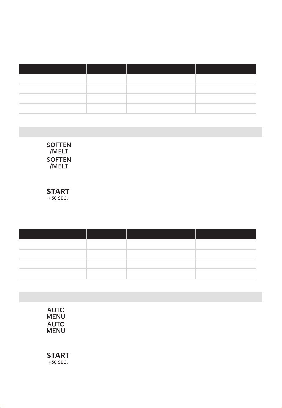
12. Soften/Melt
(1) Press once and then “So-1” will display.
(2) Press repeatedly to set the type of the food. “So-1, So-2, So-3, So-4”
are available.
(3) Press the number key “1”, “2”, or “3” to set the weight of the food.
(4) Press to start cooking.
Soften/Melt Chart
Food Display The Number Key Weight
Soften Ice Cream So-1 1, 2 Pint, 1.5 Quart
Soften Cream Cheese So-2 1, 2 3 oz, 8 oz
Melt Butter So-3 1, 2 1-2 Sticks
Melt Chocolate So-4 1, 2, 3 2 oz, 4 oz, 8oz
13. Auto Menu
(1) Press once and then “A-01” will display.
(2) Press repeatedly to set the menu you want. The 6 auto menus are
available.
(3) Press the number keys to set the weight of the food.
(4) Press to start cooking.
54
OPERATION
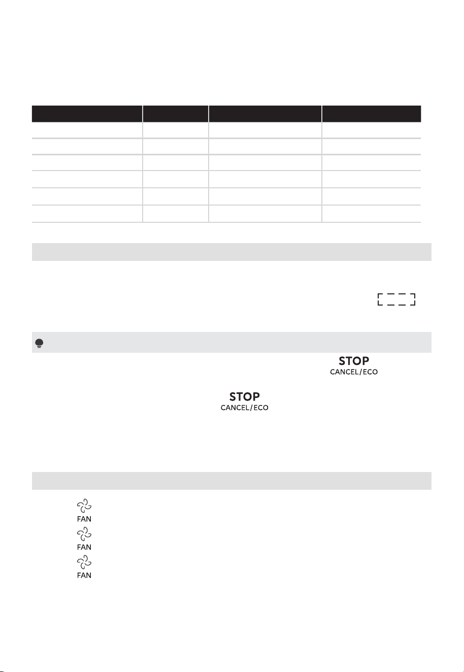
Auto Menu Chart
Food Display The Number Key Weight
Beverage A-01 1, 2, 3 1-3 cups
Fresh Vegetable A-02 1, 2, 3, 4 1-4 cups
Frozen Vegetable A-03 1, 2, 3, 4 1-4 cups
Bacon A-04 1, 2, 3 1-3 slices
Hot Dogs A-05 1, 2, 3, 4, 5, 6 1-6 pieces
Soup A-06 1, 2 1-2 cups
14. Turntable Reset Function
You can use this function to reset the utensil to its original position in the
oven after cooking. It is easy for you to take food out of the oven. The default
turntable reset function is on. During the resetting turntable process, “
”
will display.
Notes
(1) This function is valid for a complete cooking. If you press or open
and then close the oven door during cooking, this function is invalid.
(2) If you open the oven door or press during the resetting turntable
process, the oven will turn to standby mode.
(3) If the cooking time is within 5 minutes, the accuracy of the turntable is within
30 degrees.
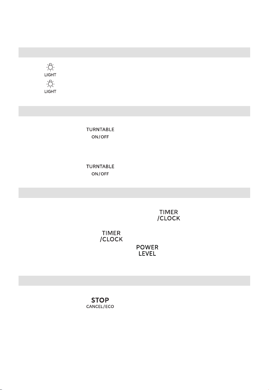
15. Setting the Vent High/Low/Off
(1) Press
(2) Press
(3) Press
once to set the vent to high and then “VENT HI” icon will display.
twice to set the vent to low and then “VENT LOW” icon will display.
thrice to set the vent to off and then “oFF” will display.
55
OPERATION
16. Setting the Light On or Off
(1) Press
(2) Press
once to set the light to on and then “on” will display.
twice to set the light to off and then “oFF” will display.
17. Setting the Turntable On or Off
To set the turntable off:
In standby mode, press once, and then “oFF” will display.
Start cooking within 5 minutes, and the turntable does not work (except for the
auto menu and defrosting).
To set the turntable on:
In standby mode, press
once, and then “on” will display.
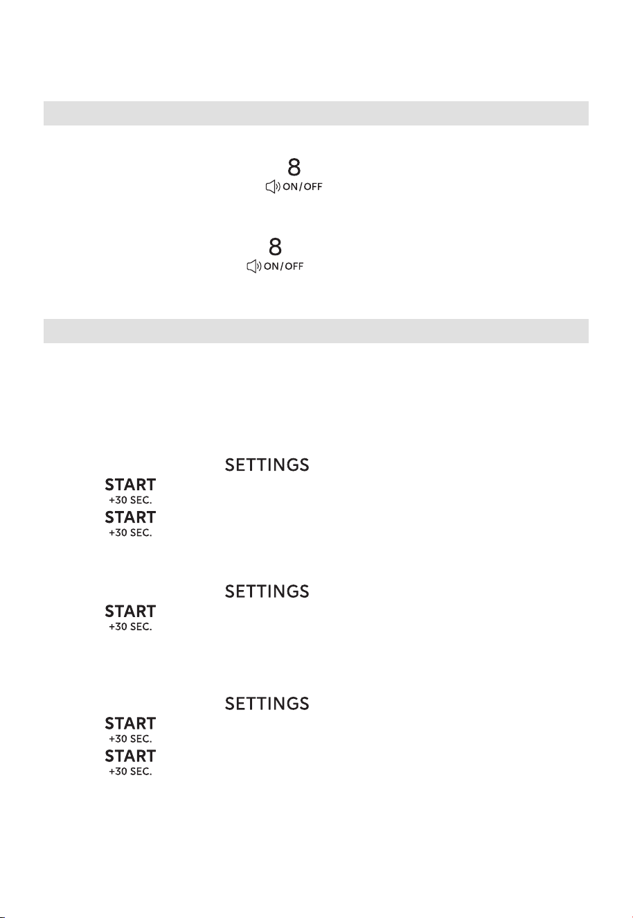
18. Inquiring Function
(1) If the clock has been set and only the kitchen timer is running, the current
time will display for two seconds by pressing
.
(2) If the kitchen timer has been set, the current remaining time will display for
two seconds by pressing
in the cooking state.
(3) In the microwave cooking state, press to inquire about the power
level. It will display for two seconds.
19. ECO Function
To enter ECO mode:
In standby mode, press
once. The screen will turn off.
To cancel ECO mode:
In ECO mode, pressing any key, or opening and closing the door will cancel it.
56
20. Mute Mode
To activate the mute mode:
In standby mode, press and hold
for 3 seconds. “oFF” will display. When
you press the key, it does not make a sound.
To deactivate the mute mode:
In mute mode, press and hold
for 3 seconds. “on” will display.
21. User Preference
21.1 Lock Function for Children
You can use this function to disable the screen buttons and prevent your child
from accidentally turning the oven on.
To activate the lock:
(1) In standby mode, press once, “SE-1” will display.
(2) Press to confirm, and then “on” and “LOCK” icon will display.
(3) Press again to activate the lock.
To deactivate the lock:
(1) In standby mode, press
once, “oFF” will display.
(2) Press
to confirm, and then “oFF” and “LOCK” icon will disappear.
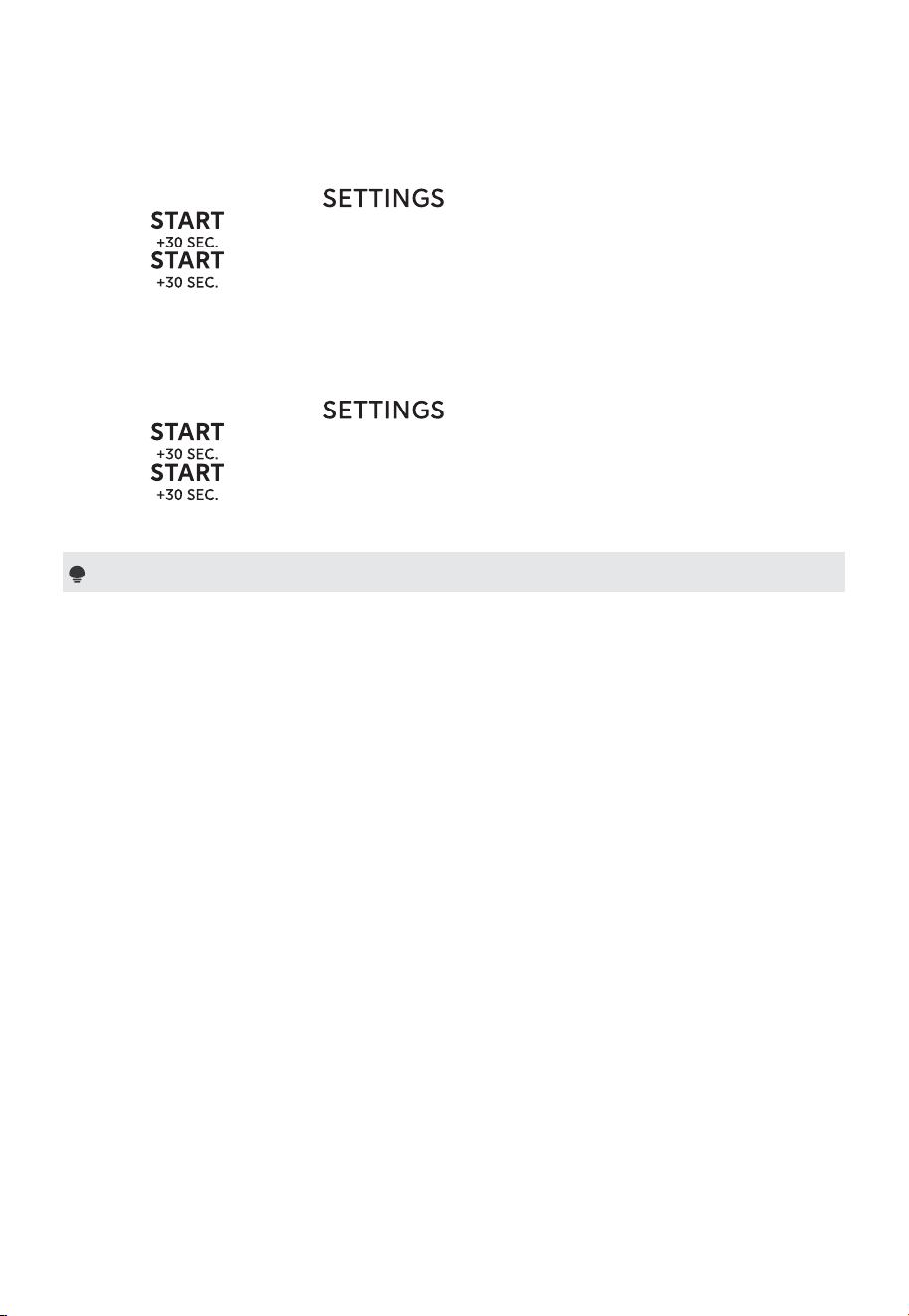
21.2 Setting the Volume On or Off
(1) In standby mode, press twice, “SE-2” will display.
(2) Press
(3) Press
, and then “Lo”, “nor”, “HI”, and “oFF” will display in a loop.
to confirm your selection when the corresponding volume
displayed.
OPERATION
57
OPERATION
21.3 Setting the Weight Unit (Lbs/Kg)
(1) In standby mode, press three times, “SE-3” will display.
(2) Press , and then “SE-3 lb” and “SE-3 kg” will display in a loop.
(3) Press to confirm your selection when the corresponding weight unit
displayed.
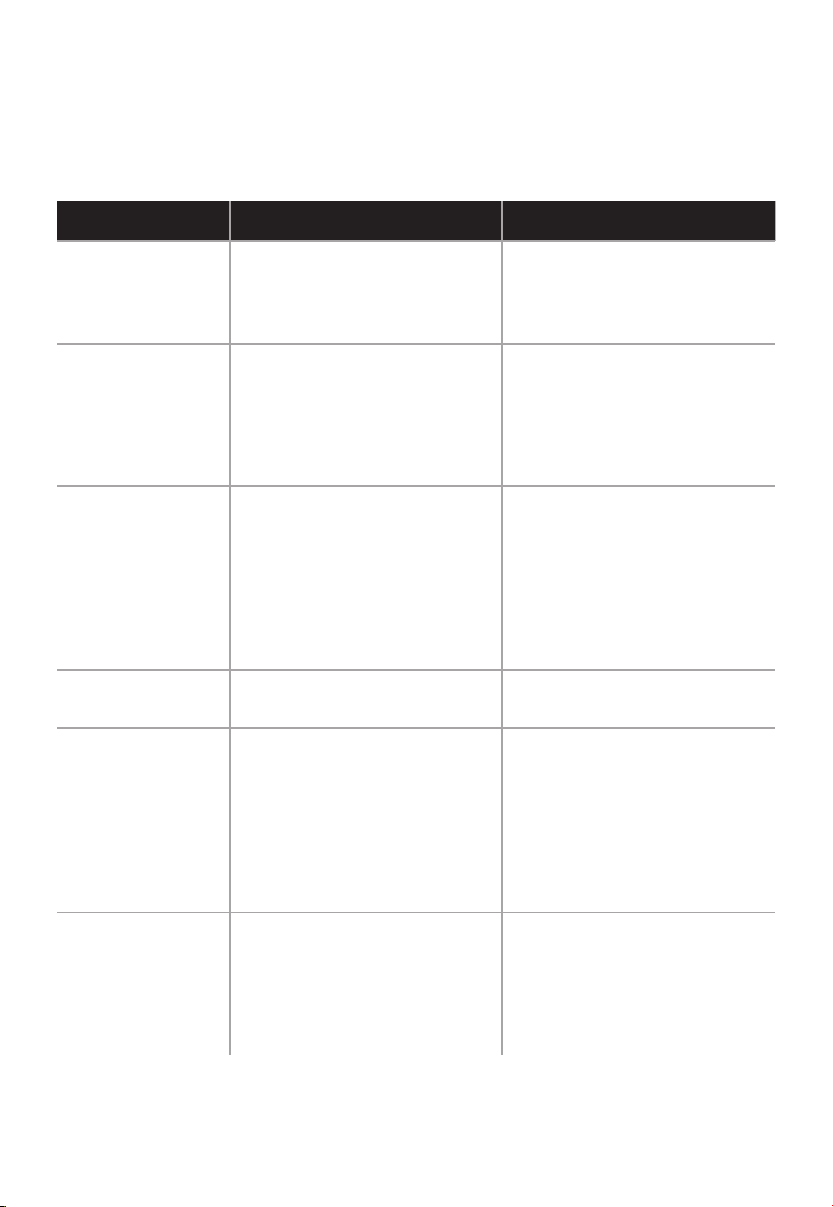
21.4 Setting the Demo Function On or Off
(1) In standby mode, press four times, “SE-4” will display.
(2) Press , and then “on” and “oFF” will display in a loop.
(3) Press to confirm your selection when the corresponding option
displayed.
Note
If the power is not cut off, the setting will be saved all the time.
58
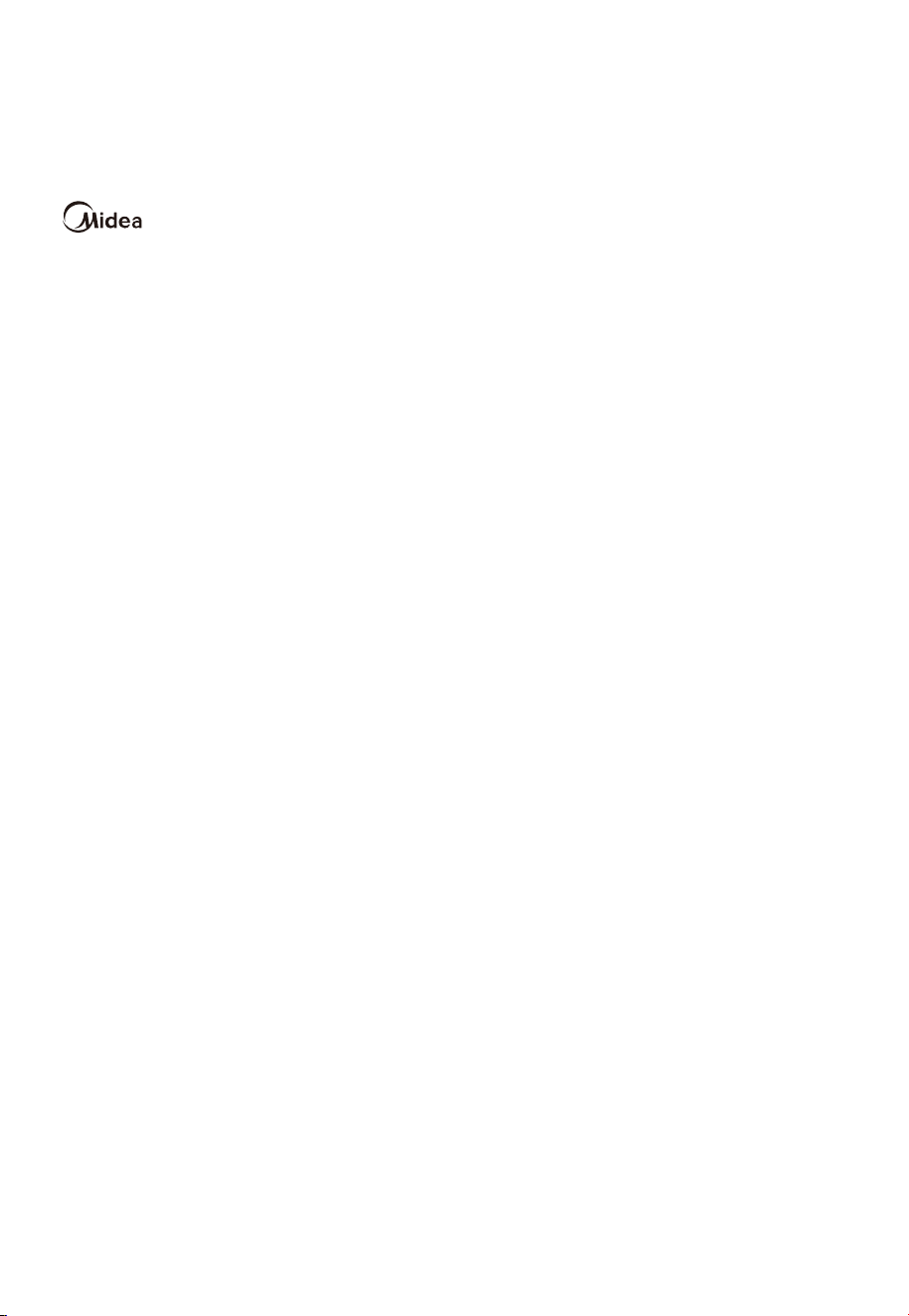
TROUBLESHOOTING
Check your problem by using the chart below and try the solutions for each problem. If the
microwave oven still does not work properly, contact the nearest authorized service center.
TROUBLE POSSIBLE CAUSE POSSIBLE REMEDY
Oven will not start
a. Electrical cord for oven is
not plugged in.
b. Door is open.
c. Wrong operation is set.
a. Plug into the outlet.
b. Close the door and try
again.
c. Check instructions.
Arcing or sparking
a. Materials to be avoided in
microwave oven were used.
b. The oven is operated when
empty.
c. Spilled food remains in the
cavity.
a. Use microwave-safe
cookware only.
b. Do not operate with oven
empty.
c. Clean cavity with wet towel.
Unevenly cooked
foods
a. Materials to be avoided in
microwave oven were used.
b. Food is not defrosted
completely.
c. Cooking time, power level is
not suitable.
d. Food is not turned or
stirred.
a. Use microwave-safe
cookware only.
b. Completely defrost food.
c. Use correct cooking time,
power level.
d. Turn or stir food.
Overcooked foods
Cooking time, power level is
not suitable.
Use correct cooking time,
power level.
Undercooked
foods
a. Materials to be avoided in
microwave oven were used.
b. Food is not defrosted
completely.
c. Oven ventilation ports are
restricted.
d. Cooking time, power level is
not suitable.
a. Use microwave-safe
cookware only.
b. Completely defrost food.
c. Check to see that oven
venti-lation ports are not
restricted.
d. Use correct cooking time,
power level.
Improper
defrosting
a. Materials to be avoided in
microwave oven were used.
b. Cooking time, power level is
not suitable.
c. Food is not turned or
stirred.
a. Use microwave-safe
cookware only.
b. Use correct cooking time,
power level.
c. Turn or stir food.
59
TRADEMARKS, COPYRIGHTS AND
LEGAL STATEMENT
logo, word marks, trade name, trade dress and all versions thereof are valuable
assets of Midea Group and/or its affiliates (“Midea”), to which Midea owns trademarks,
copyrights and other intellectual property rights, and all goodwill derived from using any
part of an Midea trademark. Use of Midea trademark for commercial purposes without
the prior written consent of Midea may constitute trademark infringement or unfair
competition in violation of relevant laws.
This manual is created by Midea and Midea reserves all copyrights thereof. No entity or
individual may use, duplicate, modify, distribute in whole or in part this manual, or bundle
or sell with other products without the prior written consent of Midea.
All the described functions and instructions were up to date at the time of printing this
manual. However, the actual product may vary due to improved functions and designs.
60
DISPOSAL AND RECYCLING
Important instructions for environment
Compliance with the WEEE Directive and Disposing of the Waster Product:
This product complies with EU WEEE Directive (2012/19/EU). This product bears a
classification symbol for waster electrical and electronic equipment (WEEE).
This symbol indicates that this product shall not be disposed
with other household wastes at the end of its service life. Used
device must be returned to official collection point for recycling
of electrical electronic devices. To find these collection systems
please contact to your local authorities or retailer where the
product was purchased. Each household performs important
role in recovering and recycling of old appliance. Appropriate
disposal of used appliance helps prevent potential negative
consequences for the environment and human health.
Compliance with RoHS Directive
The product you have purchased complies with EU RoHS Directive (2011/65/EU). It does
not contain harmful and prohibited materials specified in the Directive.
Package information
Packaging materials of the product are manufactured from
recyclable materials in accordance with our National Environ-
ment Regulations. Do not dispose of the packaging materials
together with the domestic or other wastes. Take them to the
packaging material collection points designated by the local
authorities.

61
DATA PROTECTION NOTICE
For the provision of the services agreed with the customer,
we agree to comply without restriction with all stipulations of applicable data protection
law, in line with agreed countries within which services to the customer will be delivered,
as well as, where applicable, the EU General Data Protection Regulation (GDPR).
Generally, our data processing is to fulfil our obligation under contract with you and
for product safety reasons, to safeguard your rights in connection with warranty and
product registration questions. In some cases, but only if appropriate data protection
is ensured, personal data might be transferred to recipients located outside of the
European Economic Area.
Further information are provided on request. You can contact our Data Protection
Officer via MideaDPO@midea.com. To exercise your rights such as right to object your
personal date being processed for direct marketing purposes, please contact us via
[email protected]om. To find further information, please follow the QR Code.
TWO YEAR LIMITED W
ARRANTY
This product carries a warranty stating that it will be free from defects in material and
workmanship for a period of two year from the date of purchase. This warranty is valid for the
original retail purchaser from the date of initial retail purchase and is not transferable. Keep your
original sales receipt.
IMPORTANT:
1. This warranty does not cover damages resulting from accident, misuse or abuse, lack of reasonable
care y attachments not provided with the product, loss of parts, or subjecting
the appliance to any but the specified voltage. ( Read directions carefully. )
2. This warranty is void if this product is ever used for other than private household purposes.
3. This warranty is void if this product is ever used outside of United State.
If service is required during the warranty period, properly pack your unit. We recommend using
the original carton and packing materials.
If additional assistance is needed, please contact customer assistance at:
customercare@us.toshiba-lifestyle.com
855-204-5313
Midea America Corp. expressly disclaims all responsibility for consequential damages or incidental
losses caused by use of the appliance. Some states do not allow this exclusion or limitation of
incidental or conse quential losses so the foregoing disclaimer may not apply to you.
This warranty
gives you specific legal rights, and you may also have other rights which may vary from state to state.
The serial number can be found on the back cabinet. We suggest that you record the serial number
of your unit in the space below for future reference
Model Number : ____________________
Serial Number : _____________________
Product registration is not mandatory. Failure to complete and return the card or form does
not diminish the consumer' s warranty rights.
SAVE THIS FOR YOUR RECORDS
Made in China
62
© Midea 2026 all rights reserved
MANUAL DEL USUARIO
HORNO MICROONDAS
Aviso de advertencia: Antes de utilizar este producto, lea atentamente este manual y guárdelo para
futuras consultas. El diseño y las especificaciones están sujetos a cambios sin previo aviso con el fin de
mejorar el producto. Consulte con su distribuidor o fabricante para obtener mayor información.
La imagen anterior es solo para referencia. Tome como referencia el aspecto del producto real.
MMO17S6AST
MMO17S6AWW
MMO17S6ABB

02
NOTA DE AGRADECIMIENTO
Gracias por elegir Midea. Antes de utilizar su nuevo producto Midea, lea
atentamente este manual para asegurarse de que sabe cómo manejar las
características y funciones que le ofrece su nuevo aparato de forma segura.
CONTENIDO
NOTA DE AGRADECIMIENTO ----------------------------------- 02
INSTRUCCIONES DE SEGURIDAD ----------------------------- 03
ESPECIFICACIONES ---------------------------------------------- 15
DESCRIPCIÓN GENERAL DEL PRODUCTO ------------------ 16
INSTALACIÓN DEL PRODUCTO -------------------------------- 18
FUNCIONAMIENTO----------------------------------------------- 48
RESOLUCIÓN DE PROBLEMAS
--------------------------------60
MARCAS REGISTRADAS, DERECHOS DE AUTOR Y
DECLARACIÓN LEGAL ------------------------------------------61
ELIMINACIÓN Y RECICLAJE ------------------------------------
62
AVISO DE PROTECCIÓN DE DATOS ---------------------------63
GARANTÍA LIMITADA DE DOS AÑO
---------------------------------64
03
INSTRUCCIONES DE SEGURIDAD
Uso previsto
Las siguientes recomendaciones de seguridad están destinadas a evitar riesgos
imprevistos o daños causados por una operación insegura o incorrecta del aparato.
Revise el empaque y el aparato que acaba de comprar y asegúrese de que todo esté
intacto para garantizar un funcionamiento seguro. Si encuentra algún daño, póngase en
contacto con el vendedor o distribuidor. Tenga en cuenta que por motivos de seguridad
no se permiten modificaciones ni alteraciones en el aparato. El uso no previsto puede
causar peligros y la pérdida de la garantía.
Explicación de los símbolos
Peligro
Este símbolo indica que existen peligros para la vida y la salud de las personas
debido a los gases extremadamente inflamables.
Advertencia de tensión eléctrica
Este símbolo indica que existe peligro para la vida y la salud de las personas
debido al voltaje.
Advertencia
Indica un peligro inminente con un nivel medio de riesgo que, si no se evita, puede
ocasionar la muerte o lesiones graves.
Precaución
Esta palabra de advertencia indica un peligro con un bajo grado de riesgo que, si
no se evita, puede provocar lesiones leves o moderadas.
Atención
Indica información importante, como daños materiales, pero no peligro.
Observe las instrucciones
Este símbolo indica que un técnico de servicio solo debe operar y mantener este
aparato de acuerdo con las instrucciones de funcionamiento.
Lea estas instrucciones de funcionamiento detenidamente y con atención antes de usar/
poner en marcha la unidad y manténgalas en las inmediaciones del lugar de instalación o
de la unidad para su uso posterior.

04
PRECAUCIONES PARA EVITAR
UNA POSIBLE EXPOSICIÓN
A ENERGÍA EXCESIVA DE
MICROONDAS
a. No intente utilizar este horno microondas con la
puerta abierta ya que esto puede provocar una
exposición peligrosa a la energía de microondas.
Es importante no anular ni manipular indebidamente
los dispositivos de seguridad.
b. No coloque ningún objeto entre la parte frontal
del horno y la puerta ni permita que la suciedad
o residuos de limpiadores se acumulen en las
superficies de sellado.
c. No utilice el horno microondas si está dañado. Es
importante que la puerta del horno microondas
cierre apropiadamente y que no hayan daños en:
- PUERTA (inclinación)
- BISAGRAS Y PESTILLOS (rotos o flojos)
- SELLOS DE PUERTA Y SUPERFICIES HERMÉTICAS
d. El horno no debe ser ajustado ni reparado por nadie
excepto por personal de servicio debidamente
calificado.
05
INSTRUCCIONES DE SEGURIDAD
IMPORTANTES
Al utilizar aparatos eléctricos, se deben seguir siempre
las precauciones básicas de seguridad, que incluyen
las siguientes:
ADVERTENCIA
Para reducir el riesgo de quemaduras, descargas
eléctricas, incendios, lesiones a personas o exposición
excesiva a energía de microondas.
1. Lea todas las instrucciones antes de utilizar el
aparato.
2. Lea y siga las instrucciones específicas:
"PRECAUCIONES PARA EVITAR UNA
POSIBLE EXPOSICIÓN EXCESIVA A ENERGÍA
DE MICROONDAS" que se encuentra en la
página04.
3. Este aparato debe estar conectado a tierra.
Conecte únicamente a un tomacorriente
debidamente conectado a tierra. Consulte las
"INSTRUCCIONES DE CONEXIÓN A TIERRA" que
se encuentran en la página 09.
4. Instale o coloque este artefacto solo de acuerdo
con las instrucciones de instalación proporcionadas.
5. Algunos productos como huevos enteros y
recipientes sellados, por ejemplo, frascos de vidrio
cerrados, pueden explotar por lo que no deben
calentarse en este horno.
6. Utilice este artefacto solo para el uso previsto como
se describe en este manual. No utilice productos
químicos ni vapores corrosivos en este aparato.
Este tipo de horno está diseñado específicamente

06
para calentar, cocinar o secar los alimentos. No
está diseñado para uso industrial o de laboratorio.
7. LOS CONTENIDOS CALIENTES PUEDEN CAUSAR
QUEMADURAS GRAVES. NO PERMITA QUE LOS
NIÑOS UTILICEN EL MICROONDAS. Tenga cuidado
al retirar objetos calientes.
8. No utilice este artefacto si el cable de alimentación
o enchufe están dañados, si no funciona
correctamente o si tiene daños o se ha caído.
9. Este aparato debe ser reparado únicamente
por personal de servicio calificado. Póngase en
contacto con el centro de servicio autorizado más
cercano para una evaluación, reparación o ajuste.
10. No cubra ni bloquee ninguna ranura del aparato.
11. No guarde este aparato al aire libre. No utilice
este producto cerca del agua, por ejemplo, cerca
del fregadero de la cocina, en un sótano húmedo,
cerca de una piscina o lugares similares.
12. No sumerja el cable de alimentación ni el enchufe
en el agua.
13. Mantenga el cable de alimentación alejado de
superficies calientes.
14. No permita que el cable de alimentación cuelgue
sobre el borde de la mesa o encimera.
15. Cuando limpie las superficies de la puerta y del
horno que se juntan al cerrar la puerta, utilice
solo jabones o detergentes suaves y no abrasivos
aplicándolos con una esponja o paño suave.
16. Para reducir el riesgo de incendio en el interior del
horno:
1). No cocine demasiado los alimentos. Esté atento
cuando coloque papeles, plástico u otros

07
materiales inflamables dentro del horno para
facilitar la cocción.
2). Retire los sujetadores metálicos de las bolsas
de papel o de plástico antes de colocarlas en el
horno.
3). Si los materiales dentro del horno empiezan a
arder, mantenga cerrada la puerta del horno,
apáguelo y desconecte el cable de alimentación
o desconecte la energía en la caja de fusibles o
en el panel del interruptor automático.
4). No utilice el interior del horno para almacenar
objetos. No deje productos de papel, utensilios
de cocina o alimentos en el interior del horno
cuando no esté en uso.
17. Los líquidos, como agua, café o té pueden
sobrecalentarse más allá del punto de ebullición sin
que pueda notarse que están hirviendo. No siempre
habrá burbujas o vapor de ebullición visibles al
retirar el recipiente del horno microondas.
ESTO PODRÍA PROVOCAR QUE LOS LÍQUIDOS
HIRVIENDO SE DESBORDEN REPENTINAMENTE
AL AGITAR EL RECIPIENTE O AL INTRODUCIR EN
EL LÍQUIDO UNA CUCHARA U OTRO UTENSILIO.
Para reducir el riesgo de lesiones a personas:
1) No sobrecaliente el líquido.
2) Agite el líquido antes y durante el calentamiento.
3) No utilice recipientes de lados rectos y cuello
angosto.
4) Después de calentar, deje reposar el recipiente
en el horno microondas durante un corto tiempo
antes de retirarlo.
5) Tenga mucho cuidado al insertar una cuchara u
otro utensilio en el recipiente.

08
18. No utilice ningún aparato de calefacción o de
cocina debajo del horno microondas. (Excepción:
Uso del horno microondas sobre otro aparato de
calefacción.)
19. No coloque el aparato sobre o cerca de ningún
aparato de calefacción o de cocina. (Excepción:
Uso del horno microondas sobre otro aparato de
calefacción.)
20. No coloque el aparato sobre el fregadero.
21. No almacene nada directamente sobre la superficie
del aparato cuando éste en funcionamiento.
22. Limpie las campanas extractoras con frecuencia:
no se debe permitir que se acumule grasa en la
campana ni en el filtro.
23. Cuando se flameen alimentos debajo de la
campana, encienda el ventilador.
24. Tenga cuidado al limpiar el filtro de la campana
extractora. Los productos de limpieza corrosivos,
como los limpiadores de hornos a base de lejía,
pueden dañar el filtro.
25. Este aparato es adecuado para usarlo encima de
una cocina a gas o eléctrica.
GUARDE ESTAS INSTRUCCIONES
SÓLO PARA USO DOMÉSTICO
(NO ES APTO PARA USO
COMERCIAL)
09
INSTALACIÓN DE CONEXIÓN A
TIERRA
Este aparato debe estar conectado a tierra. En caso de
que se produzca un cortocircuito eléctrico, la conexión
a tierra reduce el riesgo de descarga eléctrica al
proporcionar una vía de escape para la corriente
eléctrica. Este aparato está equipado con un cable con
conexión a tierra y un enchufe con conexión a tierra. El
enchufe debe estar conectado a un tomacorriente que
esté correctamente instalado y conectado a tierra.
ADVERTENCIA
El uso inapropiado del enchufe con conexión a tierra
puede causar una descarga eléctrica.
Consulte a un electricista o técnico de servicio
calificado si las instrucciones de conexión a tierra no se
entienden completamente, o si existen dudas sobre si
el aparato está conectado a tierra correctamente. Si es
necesario utilizar un cable de extensión, utilice solo un
cable de extensión de 3 clavijas que tenga un enchufe
con conexión a tierra de 3 clavijas y un tomacorriente
de 3 clavijas que acepte el enchufe del aparato. La
clasificación marcada del cable de extensión debe ser
igual o mayor que la clasificación eléctrica del aparato.
PELIGRO
Peligro de descarga eléctrica:
Tocar algunos de los componentes internos puede
causar lesiones personales graves o la muerte. No
intente desarmar este aparato.
ADVERTENCIA
Peligro de descarga eléctrica

10
El uso inadecuado de la conexión a tierra puede
provocar una descarga eléctrica. No enchufe el aparato
a un tomacorriente hasta que esté correctamente
instalado y conectado a tierra.
Se proporciona un cable de alimentación corto con
el propósito de reducir el riesgo de tropezarse o
enredarse con un cable más largo.
Se pueden utilizar cables de extensión solo si se usan
con cuidado.
Si se utiliza un cable de extensión:
1) La clasificación eléctrica marcada en el cable
de extensión debe ser por lo menos igual que la
clasificación eléctrica del aparato.
2) El cable de extensión debe ser un cable de 3 hilos
con conexión a tierra.
3) El cable de extensión debe colocarse de tal manera
que no cuelgue del borde de un mostrador ni de
una mesa para que no pueda ser tirado por un niño
o alguien pueda tropezarse accidentalmente.
LIMPIEZA
Asegúrese de desenchufar el aparato de la fuente de
alimentación.
1. Limpie el interior del horno después de usarlo con
un paño ligeramente húmedo.
2. Limpie los accesorios de la forma habitual con agua
jabonosa.
3. El marco y la junta de la puerta y las piezas
adyacentes deben limpiarse cuidadosamente con un
paño húmedo cuando estén sucios.
4. No utilizar limpiadores abrasivos fuertes o
raspadores afilados de metal para limpiar el vidrio
de la puerta del horno, ya que pueden rayar la
superficie, lo que puede provocar la rotura del vidrio.

11
5. Consejo de limpieza para facilitar la limpieza de las
paredes del interior del horno que pueden tocar
los alimentos cocinados: Coloque medio limón en
un recipiente, agregue 300 ml de agua y caliente al
100% de potencia de microondas durante 10minutos.
Limpie el horno con un paño suave y seco.
INTERFERENCIA DE RADIO
• El funcionamiento del horno microondas puede
causar interferencias en su radio, televisor o equipos
similares.
• Cuando hay interferencia, ésta puede reducirse o
eliminarse tomando las siguientes medidas:
1) Limpie la puerta y la superficie de sellado del
microondas.
2) Reoriente la antena receptora de la radio o la
televisión.
3) Reubique el microondas con respecto al receptor.
4) Coloque el microondas lejos del receptor.
5) Enchufe el horno microondas en un tomacorriente
diferente, de modo que el horno microondas y el
receptor estén en circuitos derivados diferentes.
• Este equipo genera, utiliza y puede irradiar energía
de radiofrecuencia y, si no se instala y utiliza
de acuerdo con las instrucciones, puede causar
interferencias perjudiciales a las comunicaciones
por radio. Sin embargo, no hay garantía de que
no se produzcan interferencias en una instalación
en particular. Si este equipo causa interferencias
perjudiciales en la recepción de radio o televisión,
que se pueden determinar apagando y encendiendo
el equipo, se recomienda al usuario que intente
corregir la interferencia mediante una o más de las
siguientes medidas:
— Reoriente o reubique la antena receptora.
12
— Aumente la separación entre el equipo y el
receptor.
— Conecte el equipo a una toma de corriente en
un circuito diferente al que está conectado el
receptor.
— Consulte al distribuidor o a un técnico
experimentado en radio o televisión para obtener
ayuda.
Este aparato cumple con la Sección 18 de las
Reglas de la FCC.
UTENSILIOS
PRECAUCIÓN
Riesgo de lesiones personales:
Los recipientes demasiado cerrados podrían explotar.
Los recipientes cerrados deben abrirse y las bolsas de
plástico deben perforarse antes de cocinar.
Consulte el manual de instrucciones en "Materiales que
puede utilizar en el horno microondas" o "Materiales
que deben evitarse en el horno microondas". Existen
algunos utensilios de cocina no metálicos que no son
seguros para utilizar en el hornos microondas. En caso
de duda, puede probar los utensilios de cocina en
cuestión siguiendo el procedimiento a continuación.
Prueba de los utensilios de cocina:
• Llene un recipiente apto para microondas con 1 taza
de agua fría (250 ml) junto con el utensilio de cocina
correspondiente.
• Cocine a máxima potencia durante 1 minuto.
• Sienta cuidadosamente la superficie de los utensilios
de cocina. Si los utensilios de cocina está calientes,
no los utilice para cocinar en el horno microondas.
• No exceda 1 minuto de cocción.
13
Materiales que puede utilizar en el horno microondas
Utensilios Observaciones
Plato para dorar
Siga las instrucciones del fabricante. La parte inferior del
plato para dorar debe estar al menos a 3/16 pulgadas (5
mm) por encima del plato giratorio. El uso incorrecto podría
causar la rotura del plato giratorio. (Para el modelo con plato
giratorio).
Vajilla
Utilice solamente envolturas aptas para microondas. Siga las
instrucciones del fabricante. No utilice platos agrietados ni
astillados.
Jarras de vidrio
Retire siempre la tapa. Utilice únicamente para calentar los
alimentos hasta que estén tibios. La mayoría de las jarras de
vidrio no son resistentes al calor y pueden romperse.
Cristalería
Utilice solo cristalería apta para horno microondas.
Asegúrese de que no contengan decoraciones metálicas. No
utilice platos agrietados ni astillados.
Bolsas de cocción para
horno
Siga las instrucciones del fabricante. No cierre con amarres
metálicos. Realice perforaciones para permitir que se escape
el vapor.
Platos y vasos de papel
Utilícelos solamente por poco tiempo de cocción o para
calentar. No deje el horno microondas desatendido durante
la cocción.
Toallas de papel
Utilícelo para cubrir los alimentos para recalentar y absorber
la grasa. Utilice con supervisión solo para una cocción de
corta duración.
Papel de horno
Utilícelo como cubierta para evitar salpicaduras o como
envoltura para cocinar al vapor.
Plástico
Utilice solamente envolturas aptas para microondas.
Siga las instrucciones del fabricante. Utilice solamente si
está etiquetado como "Apto para microondas". Algunos
recipientes de plástico se ablandan al calentarse la comida
en el interior. Las "Bolsas para hervir" y las bolsas de plástico
selladas deben cortarse, perforarse o ventilarse, como se
indica en el paquete.
Envoltura de plástico
Utilice solamente envolturas aptas para microondas. Utilícela
para envolver los alimentos durante la cocción y para retener
la humedad. No permita que la envoltura de plástico toque
los alimentos.
Termómetros
Utilice solamente termómetros aptos para microondas
(termómetros para carnes y caramelos).
Papel encerado
Utilícelo como cubierta para evitar salpicaduras y para
retener la humedad.
14
Materiales que deben evitarse en el horno microondas
Utensilios Observaciones
Bandeja de aluminio
Podría causar arcos eléctricos. Transfiera la comida a un
plato apto para microondas.
Cartón para alimentos con
asa de metal
Podría causar arcos eléctricos. Transfiera la comida a un
plato apto para microondas.
Utensilios de metal o con
adornos de metal
El metal protege el alimento de la energía de microondas.
Los adornos de metal pueden provocar arcos eléctricos.
Cierres de alambre
Podría causar arcos eléctricos y puede provocar un
incendio en el horno microondas.
Bolsas de papel Podría provocar un incendio en el horno microondas.
Espuma de plástico
La espuma de plástico puede derretir o contaminar
el líquido en el interior cuando se expone a altas
temperaturas.
Madera
La madera se seca cuando se usa en el horno microondas
y puede partirse o agrietarse.

15
ESPECIFICACIONES
Modelo
Suministro eléctrico
120VAC 60Hz
Entrada por microondas
1500 W
Salida de microondas
1000 W
MMO17S6AST/MMO17S6AWW/MMO17S6ABB
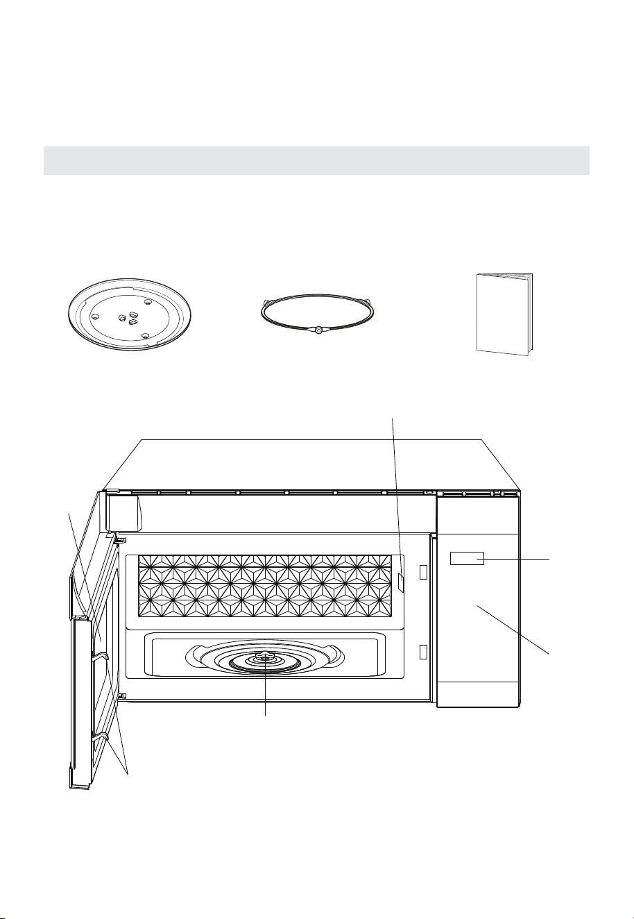
16
DESCRIPCIÓN GENERAL DEL
PRODUCTO
Nombres de las partes y accesorios del horno
En caso de que haya diferencias entre el aparato y las imágenes de este manual,
prevalecerá el producto.
Retire el horno y todos los materiales de la caja y del interior del horno.
Su horno viene con los siguientes accesorios:
Plato de cristal Conjunto de anillo giratorio Manual de instrucciones
1
2
4
5
6
3
1 Pestillos de seguridad de la puerta
2 Ventana de observación
3 Eje del motor del plato giratorio
4 Cubierta de la guía de ondas
5 Pantalla de visualización
6 Panel de control
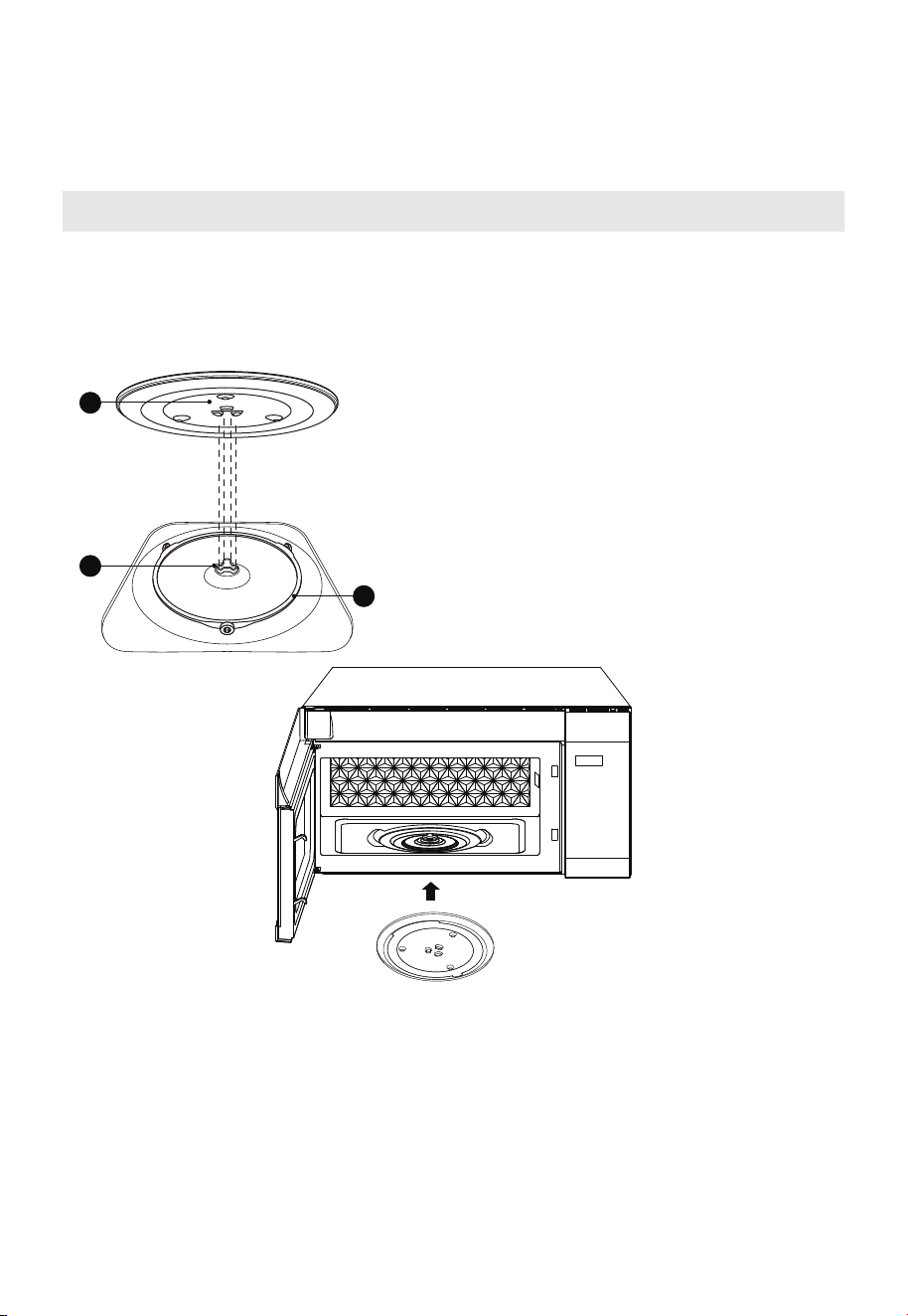
17
DESCRIPCIÓN GENERAL DEL
PRODUCTO
INSTALACIÓN DEL PLATO GIRATORIO
Limpieza del compartimento de cocción y colocación del plato giratorio. En el
caso de una nueva instalación, asegúrese de que se ha retirado todo el material
de embalaje y de cinta adhesiva del eje del plato giratorio. Antes de utilizar el
aparato para preparar alimentos por primera vez, deberá colocar el plato giratorio
correctamente. Debe limpiar el compartimento de cocción y los accesorios.
3
2
1
Cómo colocar el plato giratorio en su lugar:
1. Coloque el conjunto del anillo del plato
giratorio
③
en el interior del compartimento
de cocción. 2. Coloque el plato de cristal
①
en el anillo del plato giratorio
③
. Encaje
las líneas curvas en relieve en el centro del
fondo del plato giratorio de cristal entre
las tres ranuras del eje. Asegúrese de que
el plato de cristal
①
encaje en el eje del
plato giratorio
②
en el centro de la base del
compartimento de cocción. Los rodillos del
eje deben encajar dentro del canal ranurado
que está debajo del plato giratorio.
Notas:
1. Nunca utilice el aparato sin el plato giratorio. Asegúrese de que esté bien
encajado. El plato giratorio puede girar en el sentido de las manecillas del reloj
o en sentido contrario.
2. Nunca coloque el plato giratorio de cristal al revés. El plato giratorio de cristal
debe girar libremente.
3. El plato giratorio de cristal y el anillo del plato giratorio deben utilizarse
siempre durante la cocción.
4. Todos los alimentos y recipientes de alimentos se deben colocar siempre
sobre el plato giratorio de cristal durante la cocción.
5. Nunca restrinja el movimiento del plato giratorio.
6. Si el plato giratorio de cristal o el anillo del plato giratorio se agrietan o se
rompen, póngase en contacto con el centro de servicio autorizado más cercano.
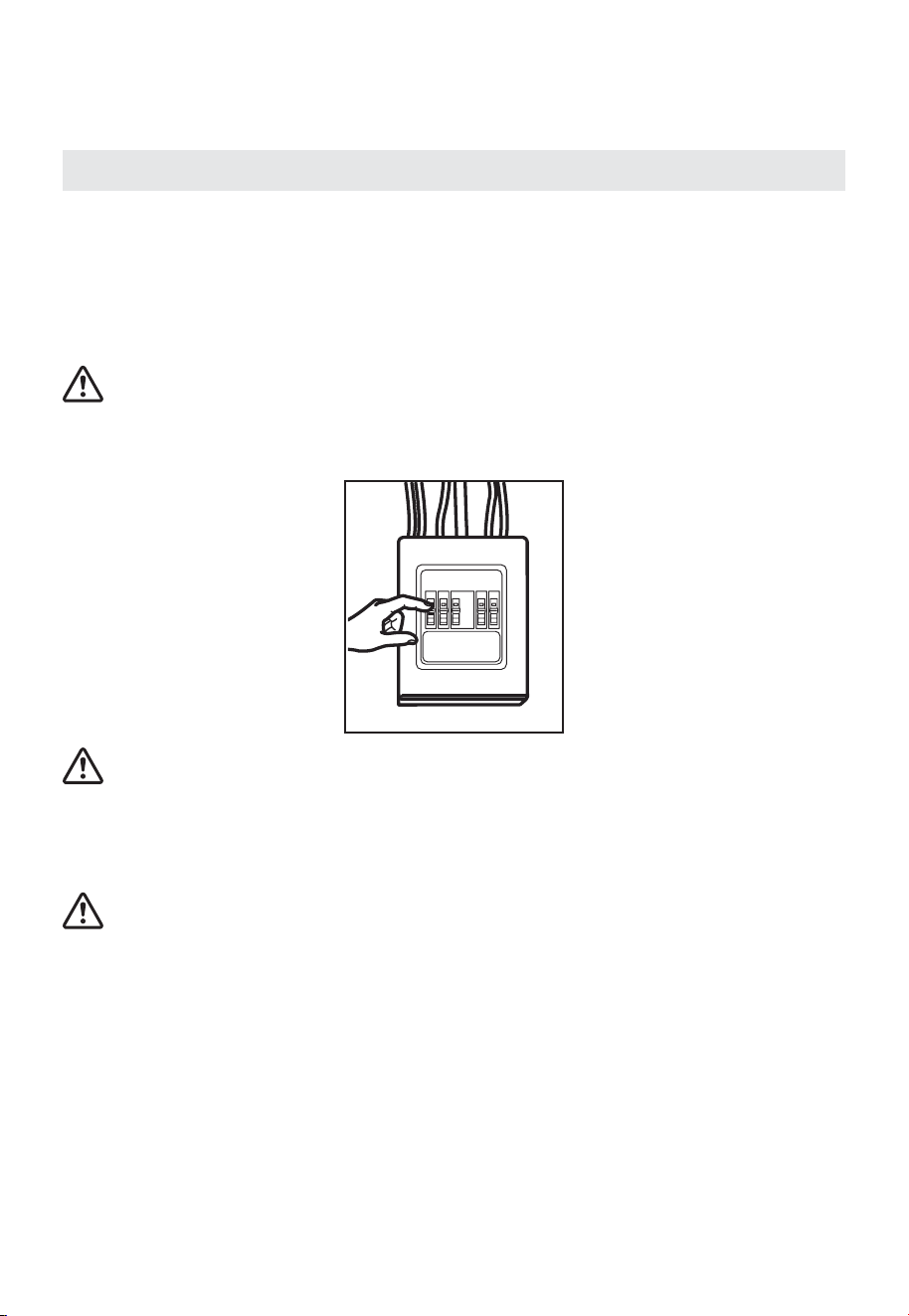
18
INSTALACIÓN DEL PRODUCTO
Instrucciones de seguridad importantes
Este producto requiere un tomacorriente de tres clavijas con conexión a tierra.
Antes de comenzar la instalación, el instalador debe comprobar la continuidad a tierra
del tomacorriente para asegurar que esté correctamente conectado a tierra.
Si no está correctamente conectado a tierra o si el tomacorriente no cumple con los
requisitos eléctricos indicados (en REQUISITOS ELÉCTRICOS), se debe contratar a un
electricista calificado para corregir cualquier deficiencia.
PRECAUCIÓN:
Por motivos de seguridad personal, retire el fusible de la vivienda o coloque el interruptor
en la posición de apagado antes de comenzar la instalación para evitar lesiones graves o
mortales por descarga eléctrica.
PRECAUCIÓN:
Por seguridad personal, la superficie de montaje debe ser capaz de soportar un peso
total de 113–135 libras (51,3–61,2 kg). Este contiene la carga del armario, el peso adicional
de este producto de 63–85 libras (28,5–38,5 kg) y cargas adicionales en horno de hasta
50 libras (22,7 kg).
PRECAUCIÓN:
Por motivos de seguridad personal, este producto no se puede instalar en gabinetes de
cocina como islas o penínsulas. Debe montarse en un gabinete superior así como en una
pared.
IMPORTANTE – LEA CUIDADOSAMENTE. POR MOTIVOS DE SEGURIDAD PERSONAL,
ESTE APARATO DEBE ESTAR CORRECTAMENTE CONECTADO A TIERRA PARA
EVITAR DESCARGAS ELÉCTRICAS GRAVES O MORTALES.
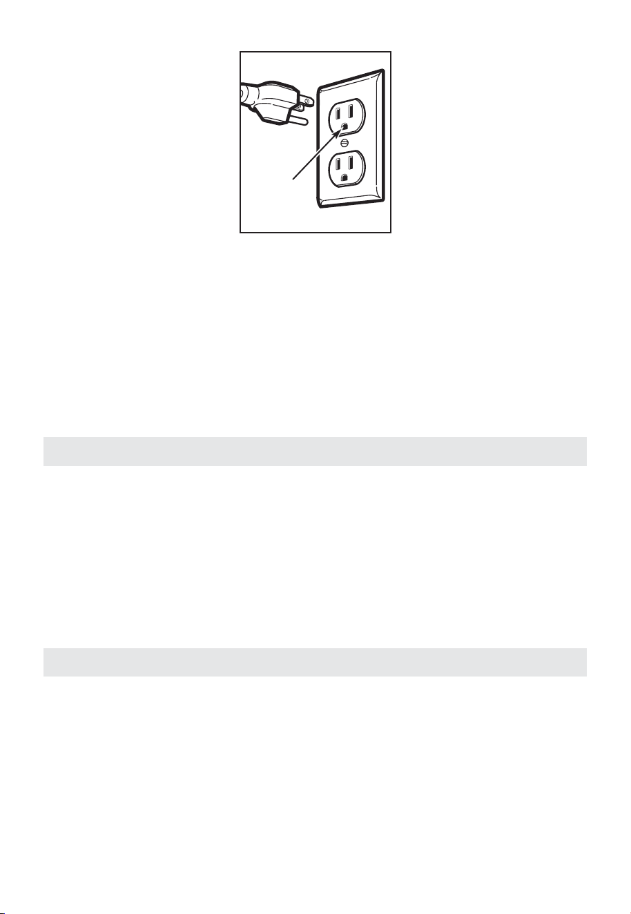
19
Asegúrese de
que haya una
conexión a tierra
adecuada antes
de usarlo.
El cable de alimentación de este aparato está equipado con un enchufe de tres clavijas
(con conexión a tierra) que se acopla a un tomacorriente estándar de tres clavijas
(con conexión a tierra) para minimizar la posibilidad de riesgo de descarga eléctrica
proveniente de este aparato.
Debe solicitar a un electricista calificado que revise el tomacorriente y el circuito para
asegurarse de que el tomacorriente tenga una conexión a tierra adecuada.
Si tiene un tomacorriente de pared estándar de dos clavijas, es muy importante que
sea reemplazado por un tomacorriente de pared de tres clavijas con conexión a tierra
adecuada, instalado por un electricista calificado. BAJO NINGUNA CIRCUNSTANCIA
CORTE, DEFORME NI RETIRE NINGUNA DE LAS PUNTAS DEL CABLE DE
ALIMENTACIÓN. NO LO UTILICE CON UN CABLE DE EXTENSIÓN.
Requisitos eléctricos
Este producto está clasificado para 120 voltios de CA, 60 hercios, 13.5 amperios y 1.55.
Conexión en kilovatios. Este producto debe conectarse a un suministro de energía
separado y dedicado con el voltaje y la frecuencia correctos. El calibre del cable
debe cumplir con los requisitos del Código Eléctrico Nacional o con el código local
vigente para esta potencia en kilovatios. El cable de alimentación y el enchufe deben
conectarse a un tomacorriente con conexión a tierra, independiente y dedicado, de 15 a
20 amperios. El tomacorriente debe ubicarse en el gabinete sobre el horno microondas.
El tomacorriente y el circuito de alimentación deben ser instalados por un electricista
calificado y cumplir con el Código Eléctrico Nacional o la normativa local vigente.
Daños durante el envío/instalación
1. Si la unidad se daña durante el envío, devuélvala a la tienda donde la compró para su
reparación o reemplazo.
2. Si la unidad ha sido dañada por el cliente, la reparación o el reemplazo serán
responsabilidad del cliente.
3. Si la unidad ha sido dañada por el instalador (si no es el cliente), la reparación o el
reemplazo se realizarán según lo acordado entre el cliente y el instalador.
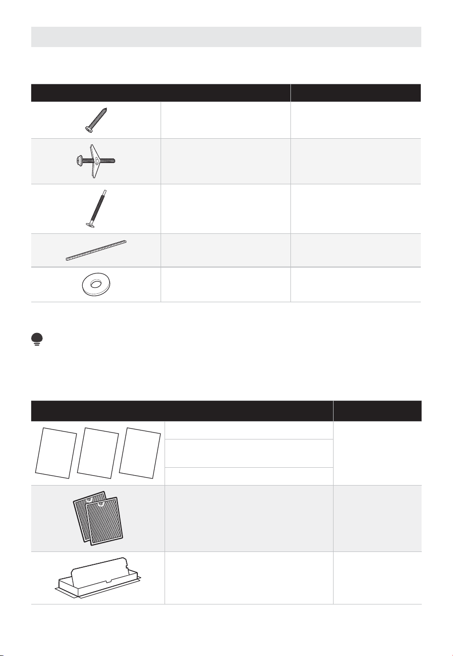
20
Partes incluidas
PAQUETE DE HERRAMIENTAS
PIEZA CANTIDAD
Tornillos para madera
( ⁄
4
" x 2")
2
Tornillos de anclaje
(y tuercas mariposa)
(
3
⁄
16
" x 3")
4
Tornillos de máquina
autoalineables
(
1
⁄
4
"-28 x 3
1
⁄
4
")
3
Ojal de nailon
(para gabinetes metálicos)
2
Cuña
6
Encontrará las herramientas de instalación en un paquete con la unidad. Compruebe que
tenga todas estas piezas.
NOTA:
Se incluyen algunas piezas adicionales.
PIEZAS ADICIONALES
PIEZA CANTIDAD
UCTIONSI
INST
NSTR
ALLATION
U
S
E
&
C
A
R
E
M
A
N
U
A
L
kciuQ ediuG
I
n
s
t
a
l
l
a
t
i
o
n
Instrucciones de instalación
1
Manual de Instrucciones y
Mantenimiento
Guía rápida de instalación
Filtros de grasa empaquetados por
separado
2
Adaptador de escape 1
1
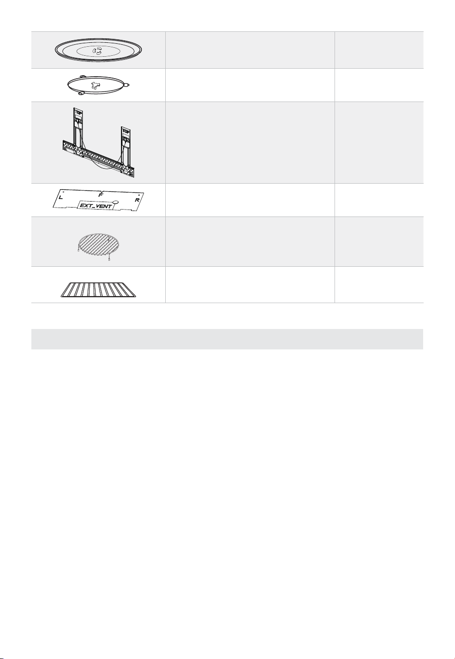
21
Plato de cristal 1
Anillo del plato giratorio 1
Instalación de los componentes 1
Plantilla de montaje para gabinete
superior
1
Para algunos modelos
Rejilla para horno de convección 1
Para algunos modelos
Estante 1
Herramientas necesarias
• Cinta métrica
• Sierra de corona
• Detector de vigas
• Nivel
• Conducto y cinta adhesiva
• Tijeras
• Destornillador Phillips n.° 1
• Taladro eléctrico
• Broca de 3/16", 1/2", 5/8"
• Bloques de madera de relleno para gabinetes
inferiores empotrados
• Tijeras para metal
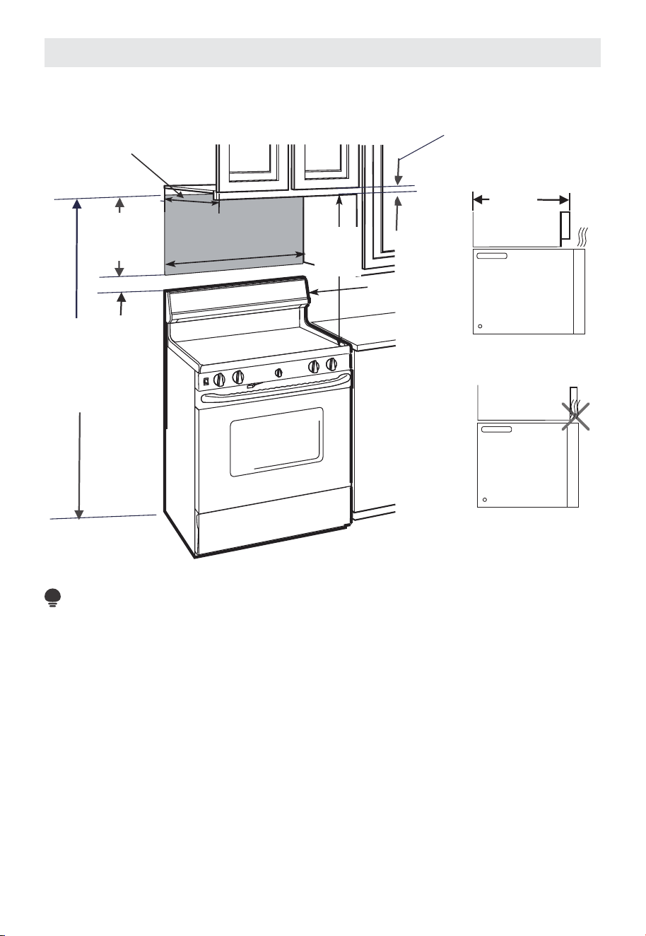
22
Espacio de montaje
ESPACIO DE MONTAJE
66"
(167.6 cm)
o más desde
el piso hasta la
parte superior
del microondas
13" Máx.
(33 cm)
30"
(76.2 cm)
mín.
2" (5.1 cm)
30" (76.2 cm)
13" Máx.
(33 cm)
1
/
4
" Separación
mínima
Protector contra
salpicaduras
Gabinete
Gabinete
16
1
/
2
"
(41.9 cm)
NOTA:
• El espacio entre los gabinetes debe ser de 30" (76.2 cm) de ancho y estar libre de
obstrucciones.
• Si va a ventilar su horno microondas al exterior, consulte la sección "Extractor de
humos" para preparar el conducto de ventilación.
• Al instalar el horno microondas debajo de gabinetes lisos y planos, siga
cuidadosamente las instrucciones de la plantilla de gabinetes superiores para dejar
espacio libre para el cable de alimentación.
• Consulte la página siguiente para obtener una guía sobre cómo colocar la placa de
montaje.
• Si la profundidad del gabinete, incluidas las puertas del gabinete, es mayor a 13",
entonces la unidad debe estar separada de la pared utilizando materiales que
soporten al menos 150 libras para permitir una entrada y salida de aire adecuadas por
la ventilación superior.
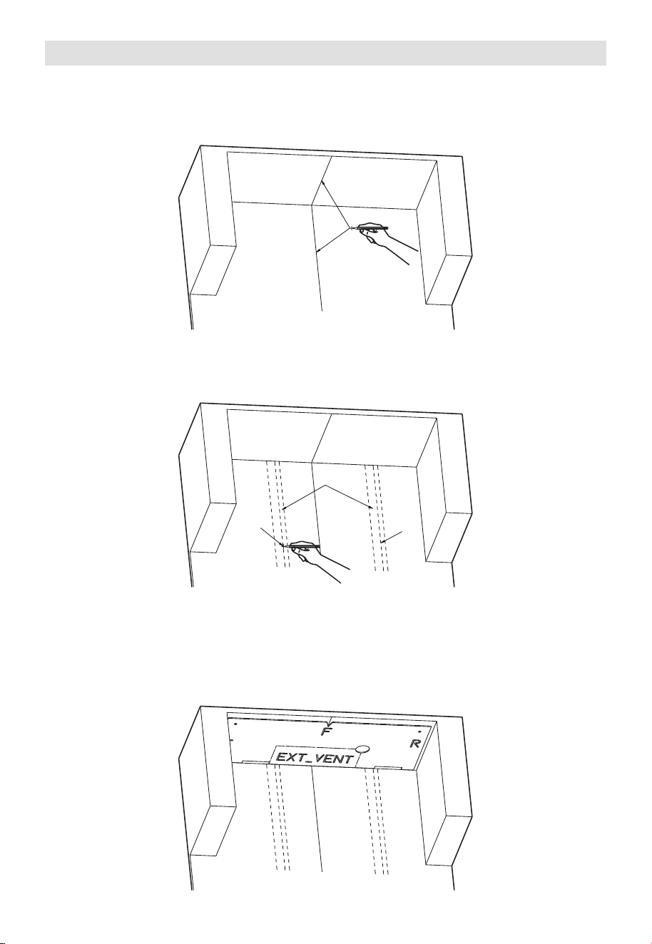
23
1. Colocación de la placa de montaje
A. Mida el ancho del área de instalación en la pared trasera y luego ubique el punto
central del ancho del área de instalación. Con un nivel o una plomada, trace una
línea central vertical a través de este punto para marcar el centro en la pared
trasera así como en la parte inferior del gabinete superior.
LÍNEA CENTRAL
B. Utilice un detector de vigas para localizar el centro de cada montante de la pared.
Dependiendo del área de instalación, puede haber 1 o 2. Cuando localice un
montante, marque los bordes izquierdo y derecho del montante, y luego trace una
línea central entre ambas marcas.
LÍNEA
CENTRAL
MONTANTES
DE PARED
LÍNEA
CENTRAL
C. Abra el paquete y saque la plantilla de montaje para gabinete superior (una
plantilla de cartón). Alinee las marcas "F" (Frente), "L" (Izquierda), "R" (Derecha) y
"EXT_VENT" con los lados correspondientes del gabinete: "FRENTE", "Izquierda",
"Derecha" y ventilación exterior (EXT_VENT). Coloque el borde trasero de la
plantilla alineado con la pared, asegúrese de que la muesca frontal esté alineada
con la línea central y colóquela plana contra la parte inferior del gabinete. Una vez
alineada, mantenga la plantilla presionada contra el gabinete.
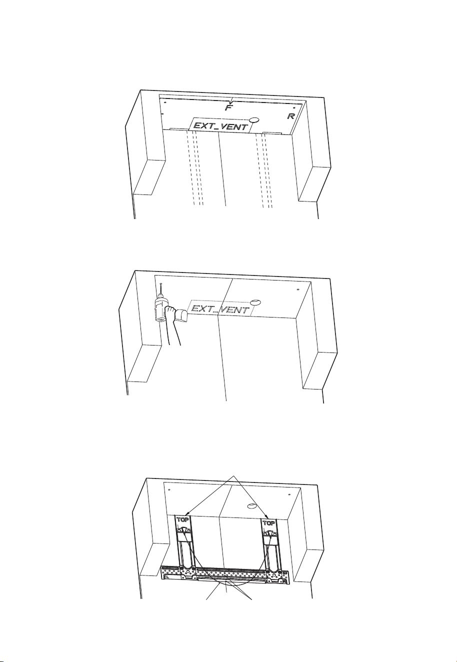
24
D. Usando los orificios en la plantilla de montaje para gabinete superior de cartón,
marque dos círculos pequeños y un círculo grande en la parte inferior del gabinete
con un lápiz. Mantenga el lápiz en posición vertical mientras marca. Si se requiere
la instalación del conducto de ventilación superior, desprenda la sección "EXT_
VENT" de la plantilla y trace su contorno en el gabinete, luego retire la plantilla.
E. Perfore dos orificios de 5/8" a través del gabinete en las dos marcas de círculos
pequeños, y un orificio de 2" en la marca del círculo grande. Si instala la ventilación
de escape superior, recorte la abertura de ventilación siguiendo el contorno "EXT_
VENT".
F. Coloque el soporte de montaje contra la pared trasera. Asegúrese de que el borde
superior del soporte quede al ras con la parte inferior del gabinete o con el reborde
del gabinete. Alinee la punta de la marca central del triángulo en el soporte con
la línea central del área de instalación dibujada en la pared. Asegúrese de que el
cordón de tracción esté orientado hacia afuera.
A ras del fondo del gabinete o del borde del gabinete
El cordón de tracción está
orientado hacia afuera
La punta del triángulo está
alineada con el centro
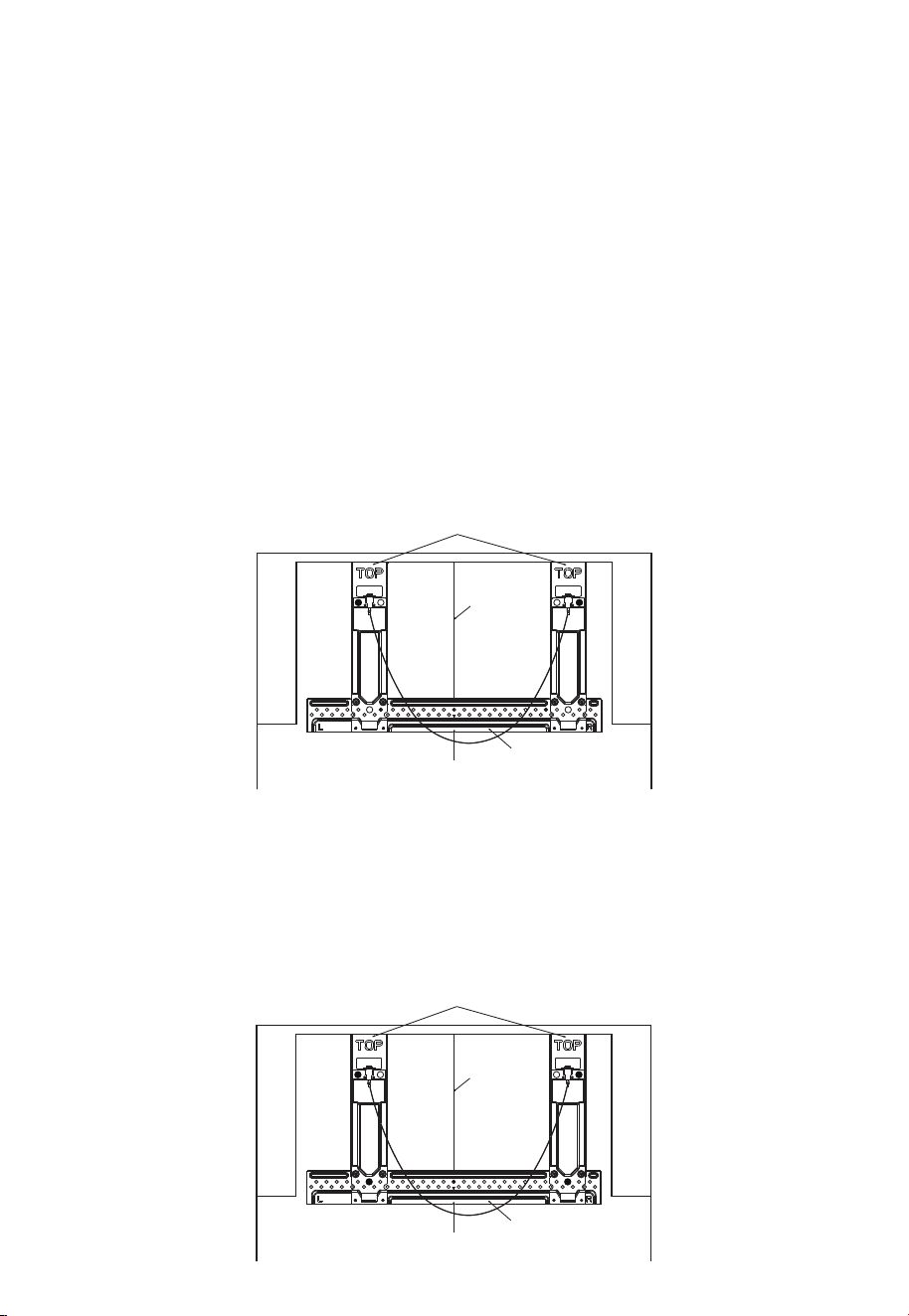
25
G. Marque las ubicaciones para los orificios de perforación
Utilice los orificios del soporte de montaje para marcar las ubicaciones de los agujeros
para taladrar. Las ubicaciones de los orificios variarán según cuántos montantes de la
pared abarque el soporte.
Caso 1 (si el soporte cubre dos montantes de la pared) requerirá cuatro orificios de
perforación. Consulte los pasos
G1 y H1 para obtener más información.
Caso 2 (si el soporte cubre solo un montante de pared) requerirá cinco orificios de
perforación. Consulte los pasos G2 y H2 para obtener más información.
G1. Marque las ubicaciones de los orificios para perforación (Caso 1: El soporte abarca
dos montantes de pared) — marque un total de 4 orificios.
1. Orificios de soporte (para tornillos de madera): En la barra horizontal inferior del
soporte, localice los dos orificios pequeños más cercanos a los ejes de los montantes
y marque sus posiciones en la pared.
2. Orificios de estabilización (para tornillos mariposa): En cada brazo vertical del soporte,
localice un orificio grande que no coincida con un montante y marque su posición en
la pared.˜Solo se requiere un orificio de montaje por brazo vertical.
LÍNEA
CENTRAL
Barra horizontal
Brazos verticales
G2. Marque las ubicaciones de los orificios para perforación (Caso 2: El soporte cubre
solo un montante de pared) — marque un total de 5 orificios.
1. Orificio de soporte (para tornillo de madera): En la barra horizontal inferior del
soporte, localice el orificio pequeño que esté más cerca de la línea central del
montante y marque su posición en la pared.
2. Orificios de estabilización (para tornillos mariposa): Marque un orificio grande en cada
brazo vertical superior y un orificio grande en la intersección de la barra horizontal
inferior con cada brazo vertical.
LÍNEA
CENTRAL
Barra horizontal
Brazos verticales
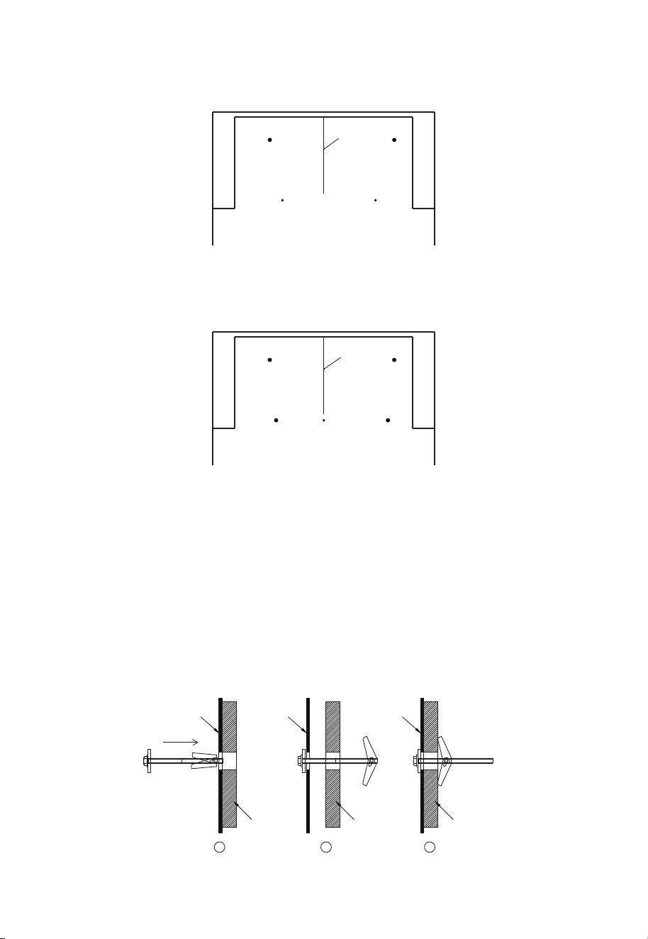
26
H.
H1. Retire el soporte de montaje (Caso 1)
Taladre a través de los pequeños orificios marcados utilizando una broca de 3/16" y
a través de los orificios grandes marcados utilizando una broca de 5/8".
LÍNEA
CENTRAL
H2. Retire el soporte de montaje (Caso 2)
Taladre a través de los pequeños orificios marcados utilizando una broca de 3/16" y
a través de los orificios grandes marcados utilizando una broca de 5/8".
LÍNEA
CENTRAL
I. Ensamble y monte el soporte
1. Inserte cada perno de palanca en el orificio central de una cuña, luego en el centro de
una tuerca mariposa para crear un conjunto de perno de palanca. Cree un conjunto de
pernos de palanca para cada orificio grande. Vuelva a colocar el soporte de montaje
en la pared como se describe en el paso F.
2. En primer lugar, fije el soporte a los orificios pequeños con los tornillos para madera.
3. A continuación, inserte el lado de la palanca de los conjuntos de pernos de palanca a
través de los orificios grandes y tire suavemente de los pernos de palanca hacia atrás
para asegurarse de que las palancas estén completamente abiertas y no se puedan
sacar, lo que indica que el anclaje es correcto.
4. Por último, apriete todos los tornillos firmemente.
1 32
Abrazadera
de montaje
Abrazadera
de montaje
Abrazadera
de montaje
PARED PARED PARED
Instalación del conjunto de pernos de palanca
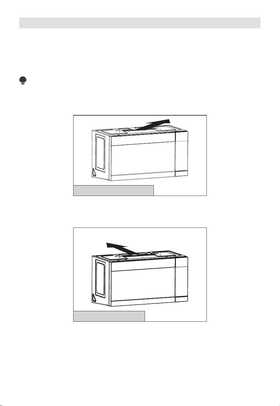
27
2. Tipos de instalación (Elija A, B o C)
Este horno microondas está diseñado para adaptarse a los siguientes tres tipos de
ventilación:
A. Escape superior exterior (conducto vertical)
B. Escape trasero exterior (conducto horizontal)
C. Recirculación (sin conducto de ventilación)
NOTA:
Lea las páginas 33 y 35 solo si planea ventilar los gases de escape al exterior. Si
planea recircular el aire de vuelta a la habitación, pase a la página 28
.
A. RECIRCULACIÓN (SIN CONDUCTO DE VENTILACIÓN)
Consulte la página 28
Los modelos se envían con recirculación de gases de escape. Algunos modelos tienen
instalado un filtro de carbón desechable para ayudar a eliminar el humo y los olores.
B. ESCAPE TRASERO EXTERIOR (CONDUCTO HORIZONTAL)
Adapte o mueva hacia
la parte trasera para el
escape trasero exterior
Consulte la página 35
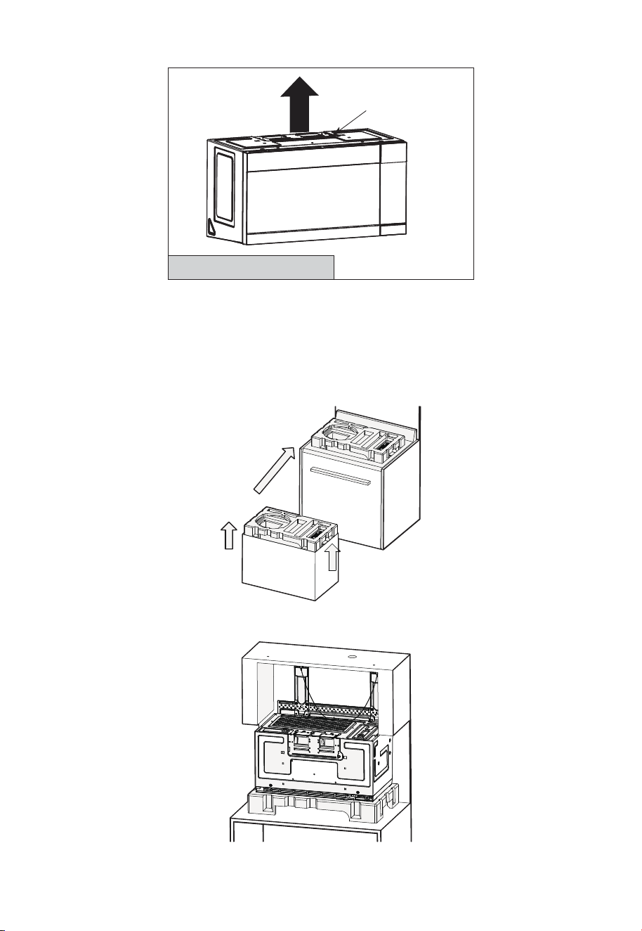
28
C. ESCAPE SUPERIOR EXTERIOR (CONDUCTO VERTICAL)
Adaptador colocado
para el escape
superior exterior
Consulte la página 40
A. Recirculación (sin conducto de ventilación)
A1. MONTAJE DEL HORNO MICROONDAS
1. Retire el bloque de espuma superior del cartón y colóquelo sobre la cocina como se
muestra en la ilustración.
Asegúrese de que el orificio redondo grande en la espuma esté ubicado en el lado
izquierdo.
2. Coloque el microondas sobre el bloque de espuma como se muestra en la ilustración,
con la parte trasera hacia arriba y la puerta hacia abajo.
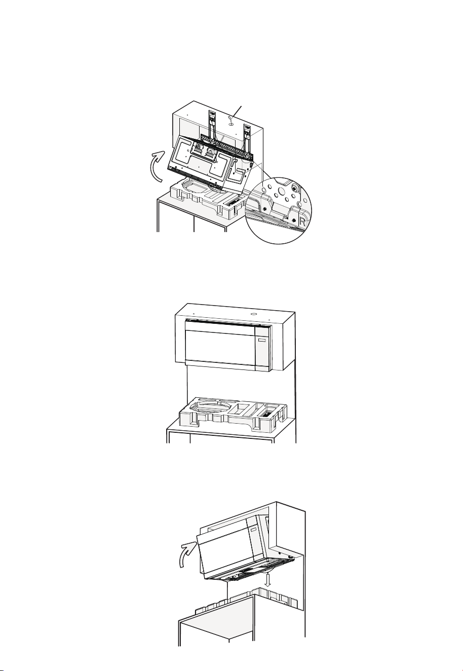
29
3. Levante el horno microondas y asegúrese de que las pestañas de montaje traseras
del microondas encajen de forma segura en las ranuras del soporte (consulte la vista
detallada ampliada). Mientras sostiene la parte frontal de la puerta del microondas, gire la
unidad hacia arriba sobre el soporte y, al mismo tiempo, pase completamente el cable de
alimentación a través del orificio para el cable de alimentación en el gabinete superior.
Apriete el cable de
alimentación
Ranuras del soporte
4. Empuje firmemente el microondas hacia arriba, en dirección a la pared, hasta que
escuche un sonido de "clic", que indica que está asegurado al soporte. A continuación,
suelte lentamente la mano con la que lo sujeta para asegurarse de que la unidad está
bien fijada en su sitio.
5. Si el microondas no está asegurado correctamente (la unidad no se mantiene en su
lugar sin el soporte de su mano), jale el cordón de liberación en el soporte de montaje
mientras empuja firmemente el microondas hacia la pared. Después, suelte el cable y
libere lentamente el microondas, asegurándose de que quede firmemente bloqueado
en su lugar.
Presione
firmemente
Tire hacia
abajo
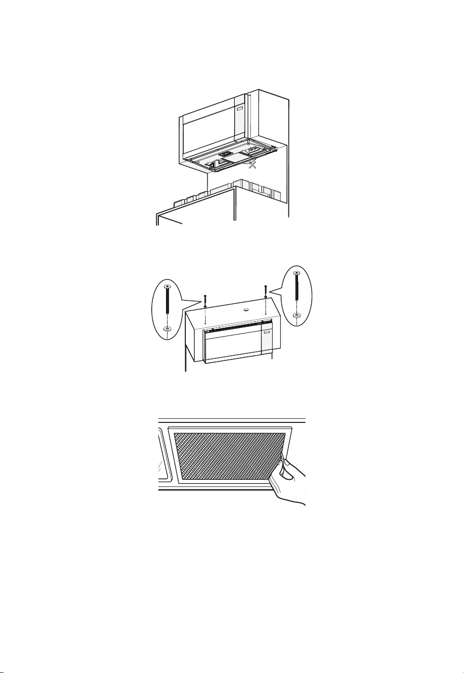
30
6. Una vez que el microondas esté instalado de forma segura, asegúrese de que el
cordón de liberación cuelgue de forma natural en su posición relajada. El cordón
de liberación es solo para la instalación y la extracción; no lo tire en ningún otro
momento, ya que esto podría provocar la caída del microondas y causar lesiones o
daños.
¡No jale hacia abajo!
7. Inserte los dos tornillos superiores a través de las cuñas y, a continuación, apriete
ambos tornillos superiores firmemente.
8. Instale los filtros de grasa.
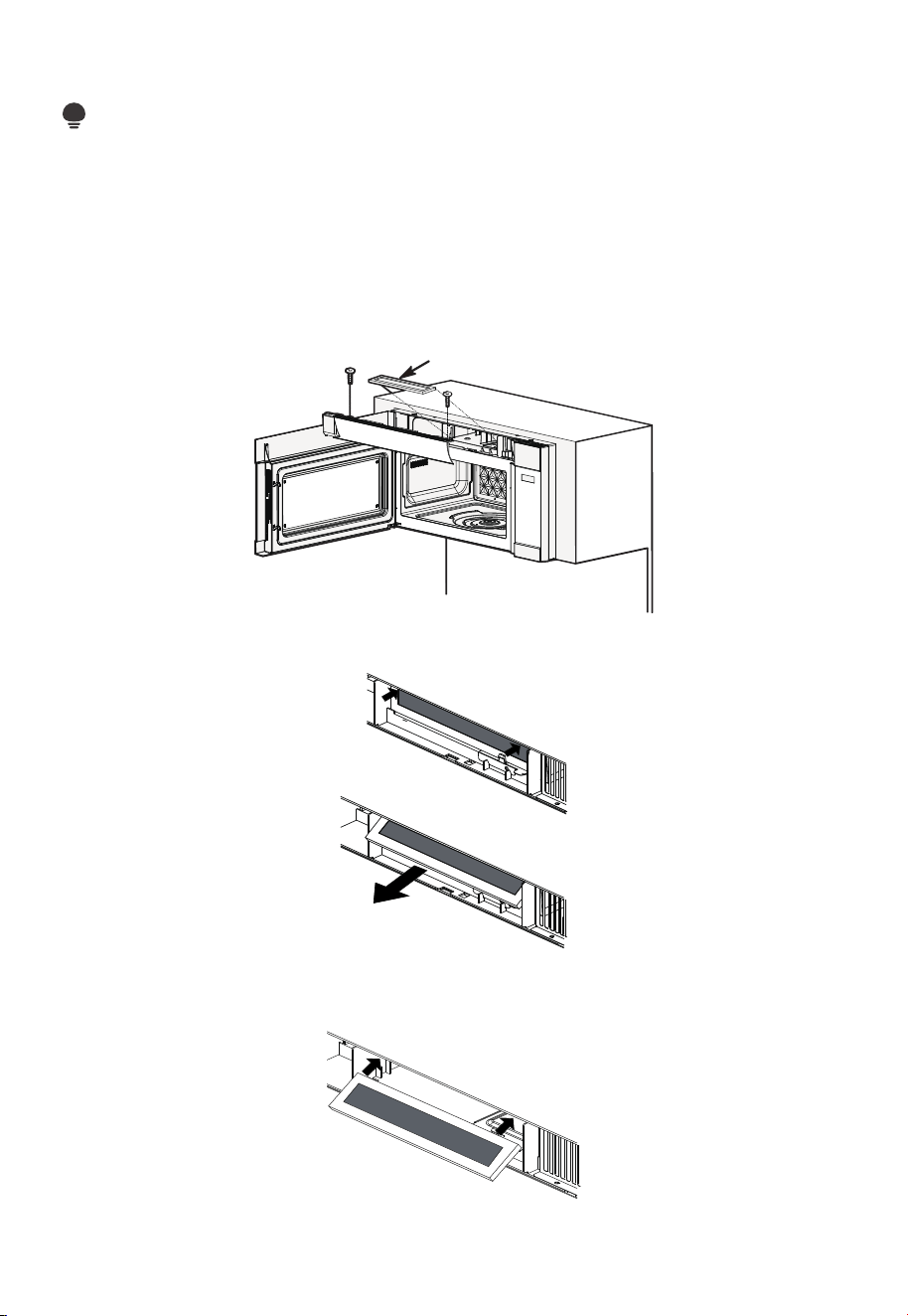
31
A2. REEMPLAZO DEL FILTRO DE CARBÓN
NOTA:
El filtro de carbón, cuando se instala en su horno microondas, se usa para instalaciones
de recirculación sin ventilación. El filtro debe cambiarse cada 6 a 12 meses dependiendo
del uso.
1. Desenchufe el horno de microondas o desconecte la alimentación.
2. Abra la puerta del horno microondas y retire los dos tornillos de montaje de la rejilla
de ventilación situados en la parte superior del microondas con un destornillador
Phillips n.º 1.
Filtro de
carbón
3. Retire el filtro de carbón empujando la parte superior del filtro hacia adentro y luego
jalándolo hacia adelante y fuera de la unidad.
4. Deslice la parte superior del nuevo filtro de carbón en la parte superior del interior del
filtro.
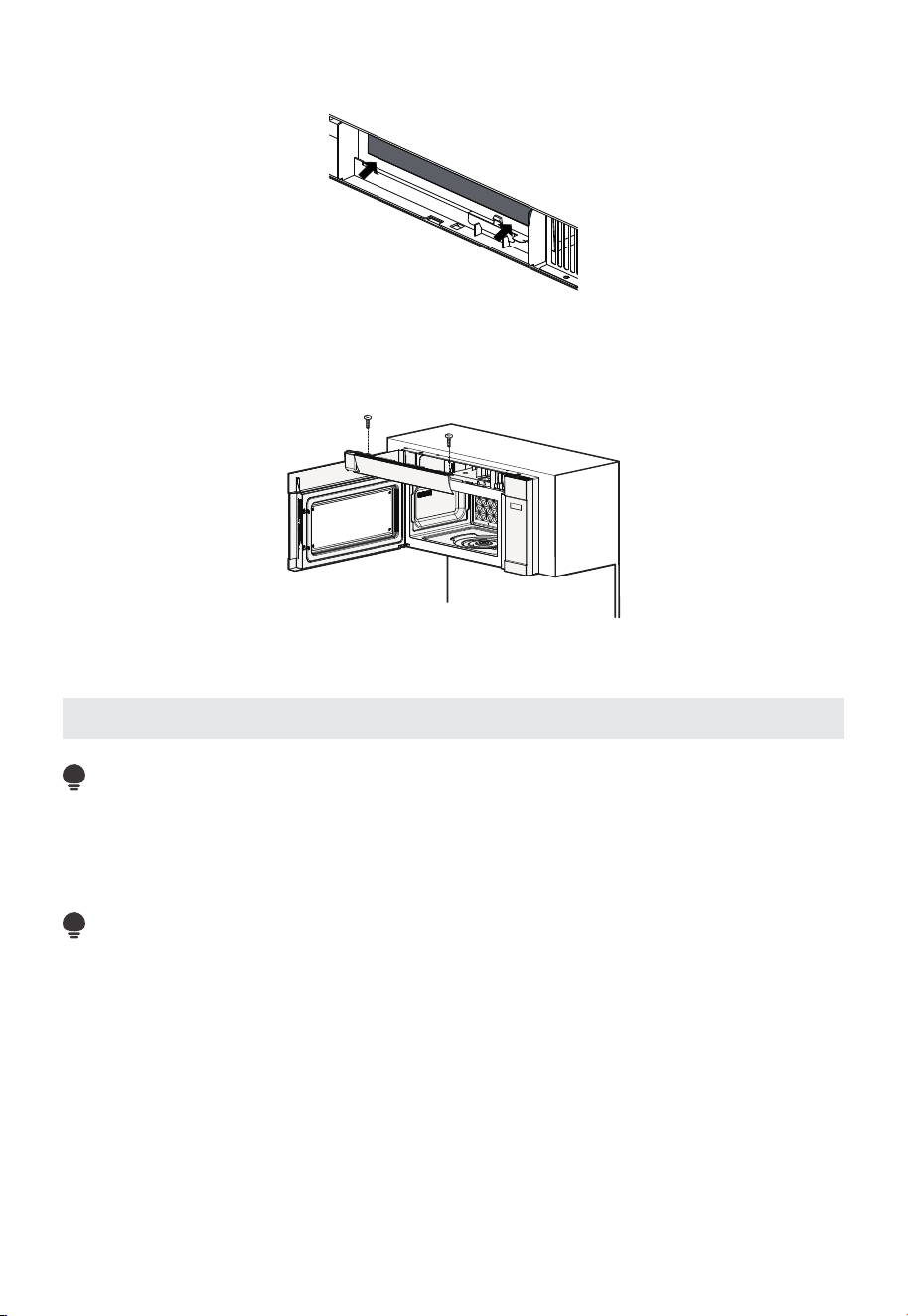
32
5. Presione la parte inferior del filtro de carbón hacia adentro para colocarlo en la
posición correcta.
6. Vuelva a instalar la rejilla de ventilación deslizando la parte inferior hasta que encaje
en su sitio. Empuje la parte superior de la rejilla hasta que encaje en su sitio y
deslícela hacia la derecha. Vuelva a colocar los dos tornillos de montaje de la rejilla de
ventilación situados en la parte superior del microondas con un destornillador Phillips
n.º 1.
7. Cierre la puerta del horno microondas. Conecte el horno microondas o vuelva a
conectar la alimentación.
Instrucciones de instalación para conductos de escape externos
NOTA:
Si necesita instalar conductos, tenga en cuenta que la longitud total del conducto de
31/4" x 10" (8.2 x 25.4 cm) rectangular o de 5" (12.7 cm) / 6" (15.2 cm) de diámetro para
conducto redondo no debe exceder los 140 pies equivalentes (42.7 m).
La ventilación exterior requiere un CONDUCTO DE ESCAPE EXTERNO. Lea lo siguiente
cuidadosamente.
NOTA:
Es importante que la ventilación se instale utilizando la ruta más directa y con el menor
número posible de codos. Esto garantiza una ventilación clara del escape y ayuda a
prevenir obstrucciones. Además, asegúrese de que las compuertas se muevan libremente
y que nada obstruya los conductos.
Conexión de escape:
El adaptador de escape ha sido diseñado para acoplarse a un conducto rectangular
estándar de 3 1/4" x 10" (8.2 x 25.4 cm).
Si se requiere un conducto circular, se debe utilizar un adaptador de transición de rectangular
a circular. Se puede utilizar un conducto de diámetro de 5" (12.7 cm) o 6" (15.2cm).
Longitud máxima del conducto:
Para una circulación de aire satisfactoria, la longitud total del conducto rectangular de
31/4" x 10" (8.2 x 25.4 cm) o del conducto redondo de 5" (12.7 cm) de diámetro / 6"
(15.2cm) de diámetro no debe exceder los 140 pies equivalentes (42.7 m).
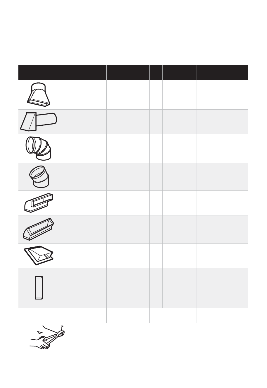
33
Los codos, transiciones, tapas de pared y techo, etc., presentan una resistencia
adicional al flujo de aire y ofrecen mayor resistencia que un conducto recto de longitud
equivalente. Al calcular la longitud total del conducto, sume las longitudes equivalentes
de todas las transiciones y adaptadores, más la longitud de todas las secciones de
conducto recto. La siguiente tabla muestra cómo calcular la longitud total equivalente de
la red de conductos, utilizando la longitud equivalente, en pies aproximados, de algunos
conductos típicos.
PIEZAS DEL CONDUCTO
LONGITUD
EQUIVALENTE
x
NÚMERO
UTILIZADO
=
LONGITUD
EQUIVALENTE
Adaptador de
transición de
rectangular a
redondo*
5 pies (1.5 m) x ( ) = Pies o metros
Tapa de pared 40 pies (12.2 m) x ( ) = Pies o metros
Codo de 90° 10 pies (3 m) x ( ) = Pies o metros
Codo de 45° 5 pies (1.5 m) x ( ) = Pies o metros
Codo de 90° 25 pies (7.6 m) x ( ) = Pies o metros
Codo de 45° 5 pies (1.5 m) x ( ) = Pies o metros
Tapa de techo 24 pies (7.3 m) x ( ) = Pies o metros
Conducto recto
de 6" (15.2 cm)
redondo o
1
/
4
" x
10"
(8.2 x 25.4 cm
rectangular)
1 pie (0.3 m) x ( ) = Pies o metros
Total de
conductos
= Pies o metros
* IMPORTANTE: Si se utiliza un adaptador de transición de
rectangular a redondo, será necesario recortar las esquinas
inferiores de la compuerta con tijeras para metal para permitir el
libre movimiento de la compuerta.
Las longitudes equivalentes de los tramos de conducto se basan en pruebas reales y
reflejan los requisitos para un buen rendimiento de ventilación con cualquier campana
extractora.
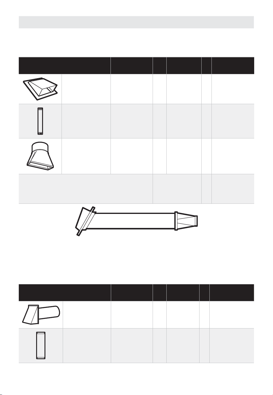
34
Conducto de escape externo
ESCAPE SUPERIOR EXTERIOR (SOLO EJEMPLO)
La siguiente tabla describe un ejemplo de una posible instalación de conducto.
PIEZAS DEL CONDUCTO
LONGITUD
EQUIVALENTE
x
NÚMERO
UTILIZADO
=
LONGITUD
EQUIVALENTE
Tapa de techo 24 pies (7.3 m) x (1) = 24 pies (7.3 m)
12 pies (3.6 m)
Conducto recto
(6"/15.2 cm
redondo)
12 pies (3.6 m) x (1) = 12 pies (3.6 m)
Adaptador de
transición de
rectangular a
redondo*
5 pies (1.5 m) x (1) = 5 pies (1.5 m)
Las longitudes equivalentes de los tramos de
conducto se basan en pruebas reales y reflejan
los requisitos para un buen rendimiento de
ventilación con cualquier campana extractora.
Longitud total = 41 pies (12.5 m)
* IMPORTANTE: Si se utiliza un adaptador de transición de rectangular a redondo, será
necesario recortar las esquinas inferiores de la compuerta con tijeras para metal para
permitir el libre movimiento de la compuerta.
ESCAPE TRASERO EXTERIOR (SOLO EJEMPLO)
La siguiente tabla describe un ejemplo de una posible instalación de conducto.
PIEZAS DEL CONDUCTO
LONGITUD
EQUIVALENTE
x
NÚMERO
UTILIZADO
=
LONGITUD
EQUIVALENTE
Tapa de pared
40 pies (12.2
m)
x (1) = 40 pies (12.2 m)
3 pies Conducto
recto (3
1
⁄
4
" x 10"
/ 8.2 x 25.4 cm
rectangular)
3 pies (0.9 m) x (1) = 3 pies (0.9 m)
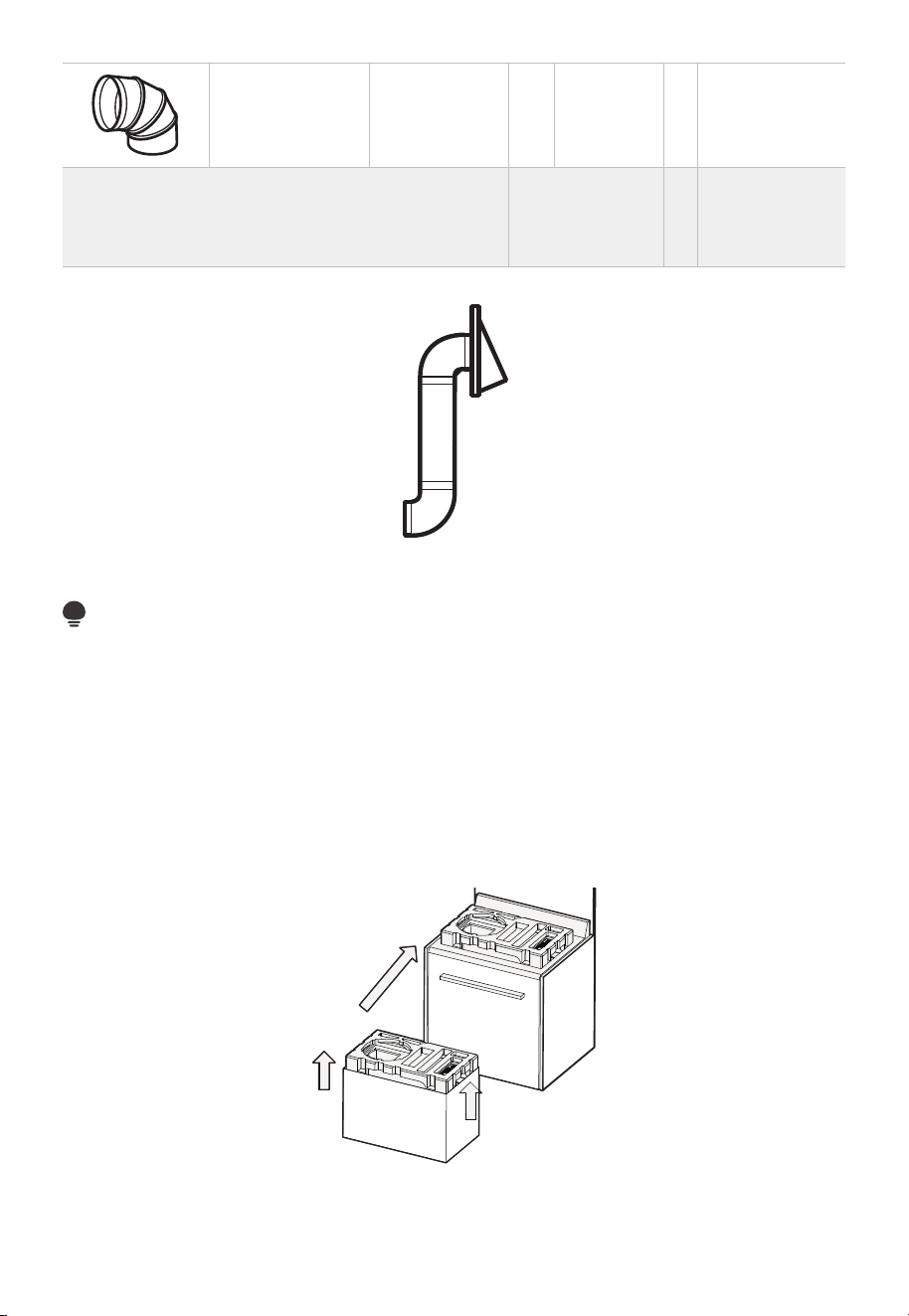
35
Codo de 90° 10 pies (3 m) x (2) = 20 pies (3 m)
Las longitudes equivalentes de los tramos de
conducto se basan en pruebas reales y reflejan
los requisitos para un buen rendimiento de
ventilación con cualquier campana extractora.
Longitud total = 63 pies (19.2 m)
NOTA:
Para el escape trasero, se debe tener cuidado de alinear el escape con el espacio entre
los montantes, o bien, la pared debe prepararse en el momento de su construcción
dejando suficiente espacio entre los montantes de la pared para instalar el escape.
B. Escape superior exterior (conducto vertical)
B1. ADAPTACIÓN DEL VENTILADOR DEL HORNO MICROONDAS PARA EL ESCAPE
TRASERO EXTERIOR
1. Retire el bloque de espuma superior del cartón y colóquelo sobre la cocina como se
muestra en la ilustración.
Asegúrese de que el orificio redondo grande en la espuma esté ubicado en el lado
izquierdo.
2. Retire los tornillos de la placa de montaje del ventilador y del microondas, así como los
tornillos que sujetan el ventilador al microondas. Guarde los tornillos. A continuación,
retire la placa de montaje del ventilador.
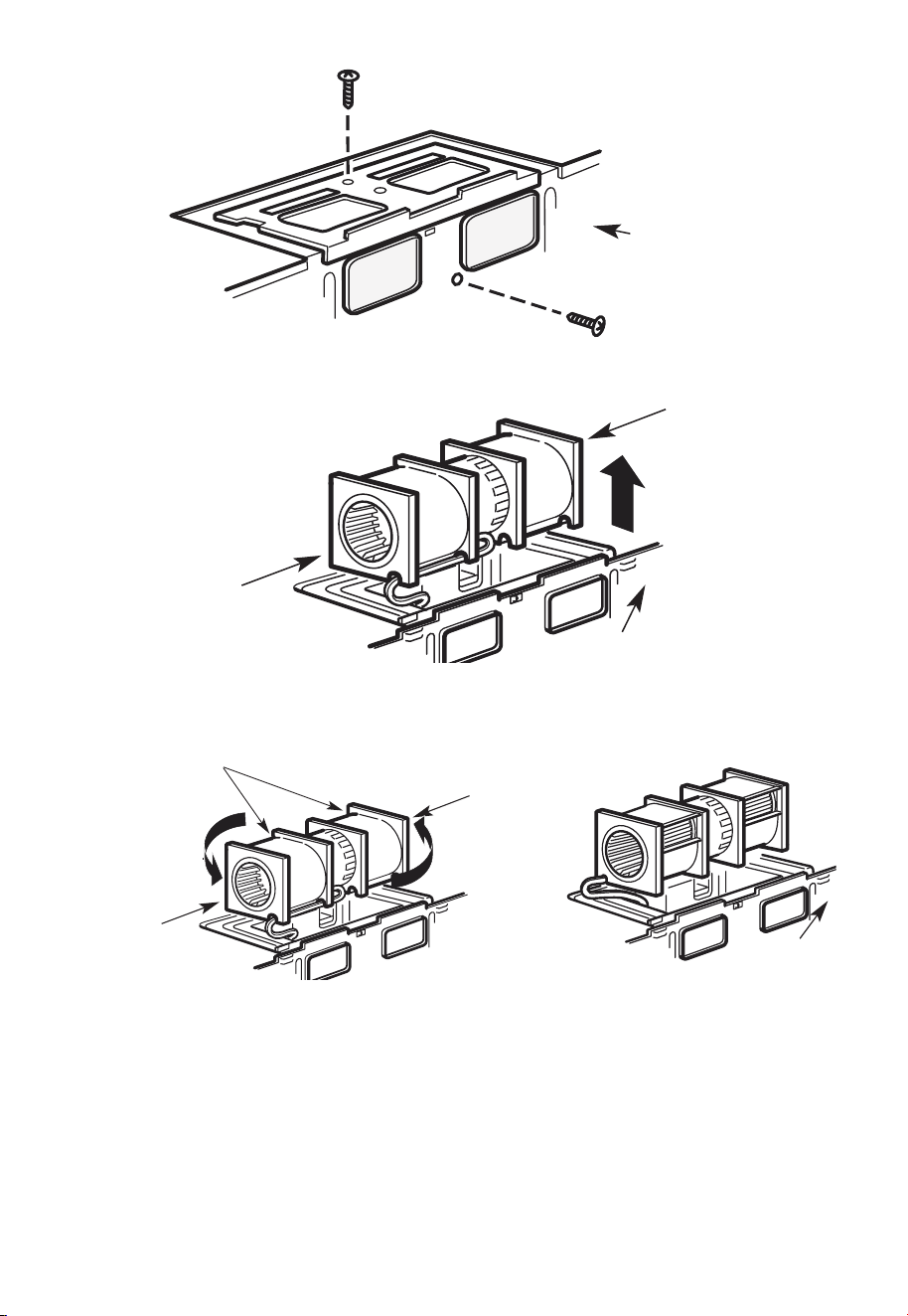
36
Parte
trasera
del horno
microondas
3. Extraiga con cuidado el ventilador. Los cables se extenderán lo suficiente como para
permitirle ajustar el ventilador.
Parte trasera del
horno microondas
Extremo
B
Extremo
A
4. Gire el ventilador 180°, como se muestra en el diagrama.
Parte trasera
del horno
microondas
Después de enrollar
Antes: Aberturas
de las aspas
del ventilador
orientadas hacia
adelante
Extremo
B
Extremo
A
5. Retire las placas desmontables (solo en algunos modelos) de la parte posterior de la
unidad con unas tijeras. Placas desmontables:
Corte las 4 pestañas de cada panel desmontable y retire las placas desmontables
metálicas para permitir el flujo de aire trasero. Tenga cuidado de eliminar cualquier
borde afilado que se haya creado al retirar las placas desmontables.
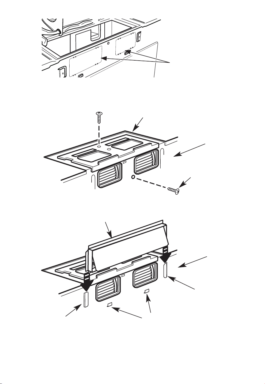
37
Parte trasera del
horno microondas
6. Vuelva a colocar el ventilador en la unidad, reinstale la placa de montaje del ventilador
y apriete los tornillos que fijan el microondas al ventilador, así como los tornillos que
fijan el ventilador a la placa de montaje.
Placa del ventilador
Parte trasera
del horno
microondas
Tornillo del
motor del
ventilador
7. Fije el adaptador de escape a la parte trasera del horno deslizándolo en las guías de la
parte posterior del horno, junto a la placa de montaje del ventilador.
Parte trasera
del horno
microondas
Guía
Pestañas de bloqueo
Guía
Adaptador
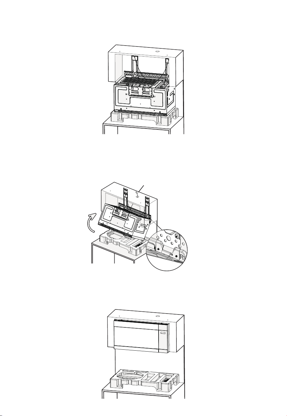
38
B2. MONTAJE DEL HORNO MICROONDAS
1. Coloque el microondas sobre el bloque de espuma como se muestra en la ilustración,
con la parte trasera hacia arriba y la puerta hacia abajo.
2. Levante el horno microondas y asegúrese de que las pestañas de montaje traseras
del microondas encajen de forma segura en las ranuras del soporte (consulte la vista
detallada ampliada). Mientras sostiene la parte frontal de la puerta del microondas,
gire la unidad hacia arriba sobre el soporte y, al mismo tiempo, pase completamente el
cable de alimentación a través del orificio para el cable de alimentación en el gabinete
superior.
Apriete el cable de
alimentación
Ranuras del soporte
3. Empuje firmemente el microondas hacia arriba contra la pared hasta que escuche
un sonido de "clic", lo que indica que está asegurado correctamente en el soporte. A
continuación, suelte lentamente la mano con la que lo sujeta para asegurarse de que
la unidad está bien fijada en su sitio.
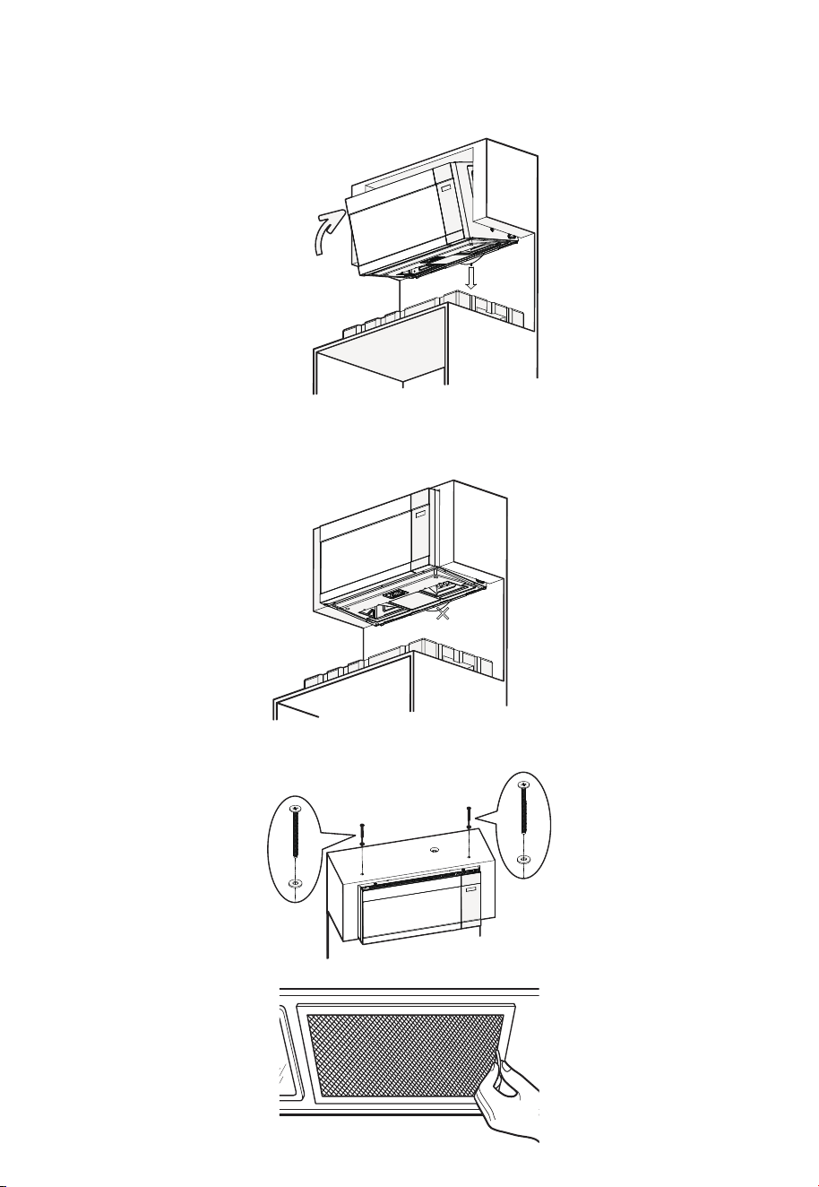
39
4. Si el microondas no está asegurado correctamente (no se escucha el sonido de "clic"),
jale hacia abajo el cordón de liberación en el soporte de montaje mientras empuja
firmemente el microondas hacia la pared. Después, suelte el cable y libere lentamente
el microondas, asegurándose de que quede firmemente bloqueado en su lugar.
Presione
firmemente
Tire hacia
abajo
5. Una vez que el microondas esté instalado de forma segura, asegúrese de que el cordón
de liberación cuelgue de forma natural en su posición relajada. El cordón de liberación
es solo para la instalación y la extracción; no lo tire en ningún otro momento, ya que
esto podría provocar la caída del microondas y causar lesiones o daños.
¡No jale hacia abajo!
6. Inserte los dos tornillos superiores a través de las cuñas y apriete ambos tornillos
superiores de manera segura.
7. Instale los filtros de grasa.
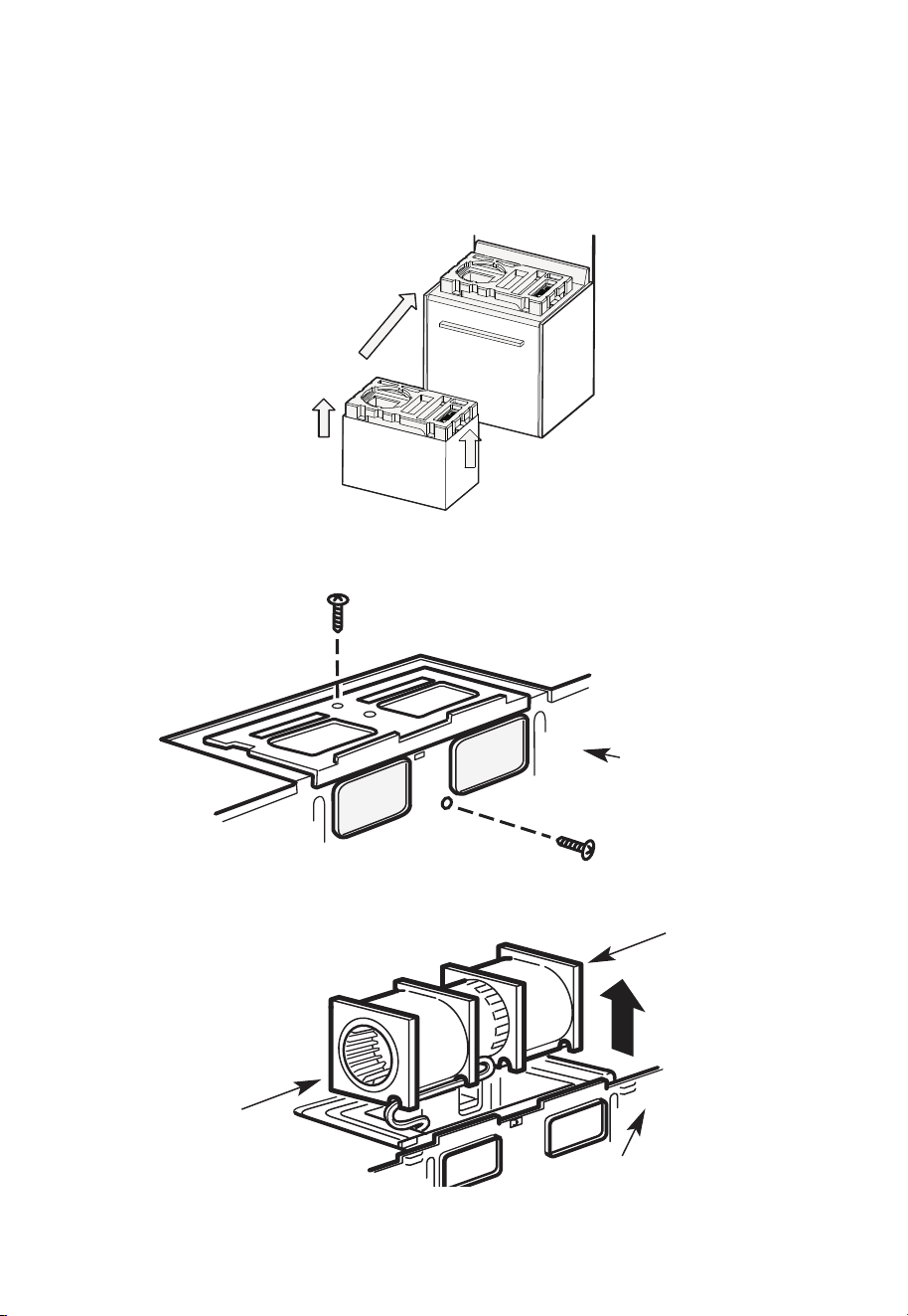
40
C. Escape superior exterior (conducto vertical)
C1. ADAPTACIÓN DEL VENTILADOR DEL HORNO MICROONDAS PARA EL ESCAPE
TRASERO EXTERIOR
1. Retire el bloque de espuma superior del cartón y colóquelo sobre la cocina como se
muestra en la ilustración.
Asegúrese de que el orificio redondo grande en la espuma esté ubicado en el lado
izquierdo.
2. Retire los tornillos de la placa de montaje del ventilador y del microondas, así como los
tornillos que sujetan el ventilador al microondas. Guarde los tornillos. A continuación,
retire la placa de montaje del ventilador.
Parte trasera
del horno
microondas
3. Extraiga con cuidado el ventilador. Los cables se extenderán lo suficiente como para
permitirle ajustar el ventilador.
Parte trasera del
horno microondas
Extremo
B
Extremo
A
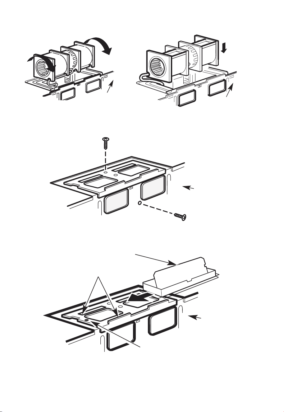
41
4. Gire el ventilador 90° como se muestra en la ilustración, luego coloque el ventilador
hacia abajo.
Parte trasera del
horno microondas
Parte trasera del
horno microondas
5. Vuelva a colocar el ventilador en la unidad, reinstale la placa de montaje del ventilador
y apriete los tornillos que fijan el microondas al ventilador, así como los tornillos que
fijan el ventilador a la placa de montaje.
Parte trasera
del horno
microondas
6. Coloque el adaptador de escape en la parte superior de la placa de montaje del
ventilador deslizándolo en las guías de la placa de montaje del ventilador.
Parte trasera
del horno
microondas
Pestaña de bloqueo
Guía
Adaptador
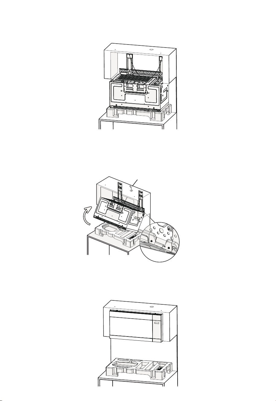
42
C2. MONTAJE DEL HORNO MICROONDAS
1. Coloque el microondas sobre el bloque de espuma como se muestra en la ilustración,
con la parte trasera hacia arriba y la puerta hacia abajo.
2. Levante el horno microondas y asegúrese de que las pestañas de montaje traseras del
microondas encajen de forma segura en las ranuras del soporte (ver la vista detallada
ampliada).˜ Mientras sostiene la parte frontal de la puerta del microondas, haga girar
la unidad hacia arriba sobre el soporte y, al mismo tiempo, pase completamente el
cable de alimentación por el orificio para el cable de alimentación en la parte superior
del gabinete.
Apriete el cable de
alimentación
Ranuras del soporte
3. Empuje firmemente el microondas hacia arriba contra la pared hasta que escuche
un sonido de "clic", lo que indica que está asegurado correctamente en el soporte. A
continuación, suelte lentamente la mano con la que lo sujeta para asegurarse de que
la unidad está bien fijada en su sitio.
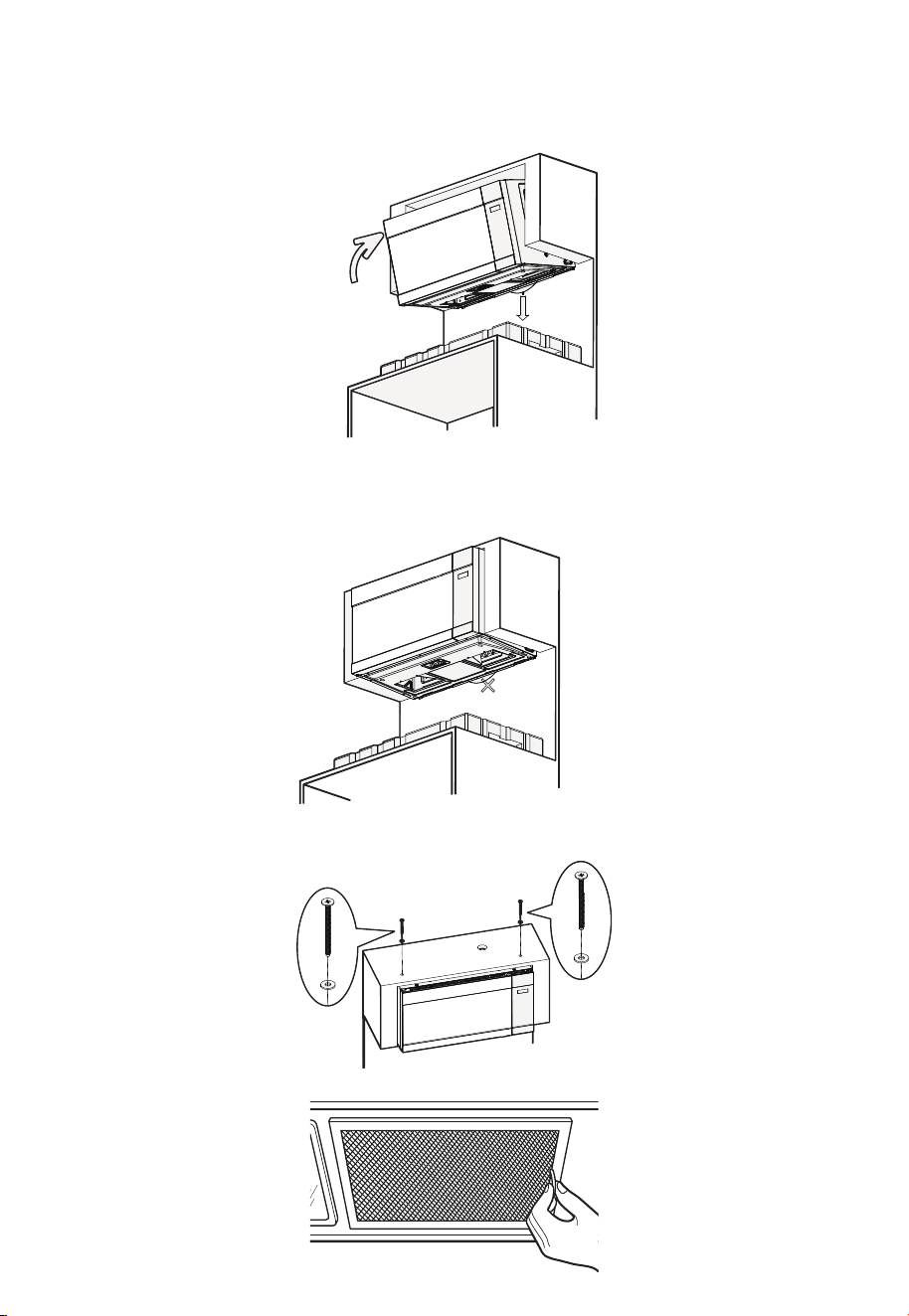
43
4. Si el microondas no está asegurado correctamente (no se escucha el sonido de "clic"),
jale hacia abajo el cordón de liberación en el soporte de montaje mientras empuja
firmemente el microondas hacia la pared. Después, suelte el cable y libere lentamente
el microondas, asegurándose de que quede firmemente bloqueado en su lugar.
Presione
firmemente
Tire hacia
abajo
5. Una vez que el microondas esté instalado de forma segura, asegúrese de que el cordón
de liberación cuelgue de forma natural en su posición relajada. El cordón de liberación
es solo para la instalación y la extracción; no lo tire en ningún otro momento, ya que
esto podría provocar la caída del microondas y causar lesiones o daños.
¡No jale hacia abajo!
6. Inserte los dos tornillos superiores a través de las cuñas y apriete ambos tornillos
superiores de manera segura.
7. Instale los filtros de grasa.
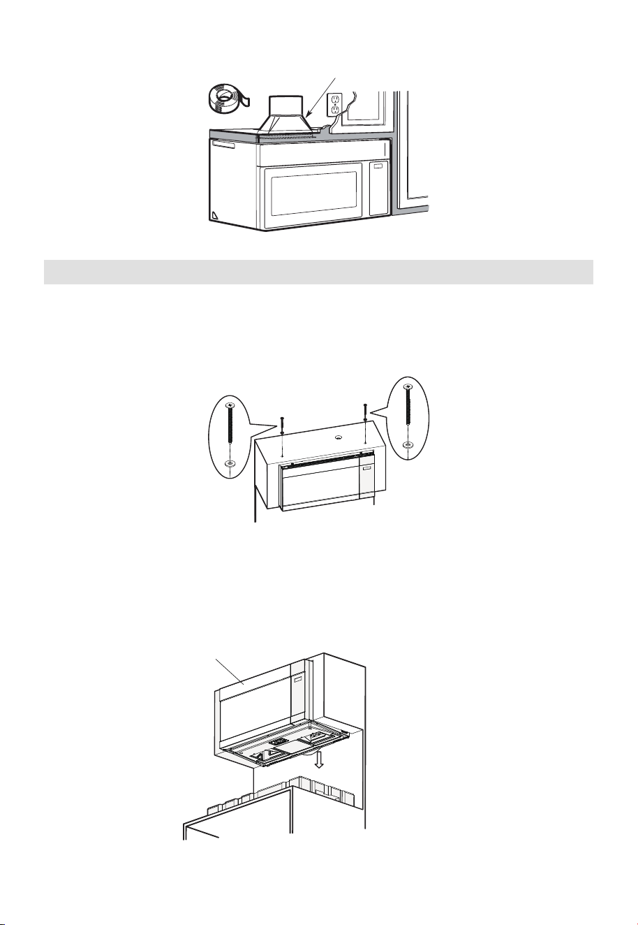
44
8. Conecte el conducto de ventilación a la parte superior del gabinete.
Conducto de la vivienda
3. Método de desmontaje del horno microondas
Si el microondas necesita ser reparado o reemplazado más adelante, siga los pasos
que se indican a continuación:
A. Retire los pernos que aseguran la parte superior del microondas al gabinete. Si es
necesario, desconecte el conducto de ventilación superior.
B. Sostenga con las manos el borde frontal superior de la puerta del microondas.
A continuación, jale firmemente el cordón de liberación ubicado en la parte
inferior del microondas. La parte superior del microondas se soltará; no suelte el
microondas en este momento.
1. Sostenga con la mano la parte
superior frontal de la puerta del
microondas
2. Tire de la cuerda de
liberación hacia abajo
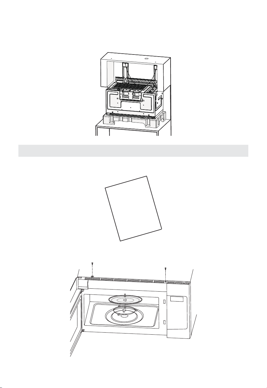
45
C. En este punto, gire lentamente el microondas hacia abajo y bájelo hasta la
superficie para completar la extracción. Sostenga el microondas para que no caiga
sobre la superficie inferior. Si tiene el bloque de espuma superior del embalaje
original, puede usarlo para amortiguar el microondas. De lo contrario, bájelo con
cuidado sobre la superficie inferior.
Antes de utilizar el microondas
1. Asegúrese de que el horno microondas se haya instalado según las instrucciones.
INSTALLATION
INSTRUCTIONS
2. Retire todo el material de embalaje del horno microondas.
3. Instale el anillo del plato giratorio y la bandeja de vidrio en el interior del microondas.
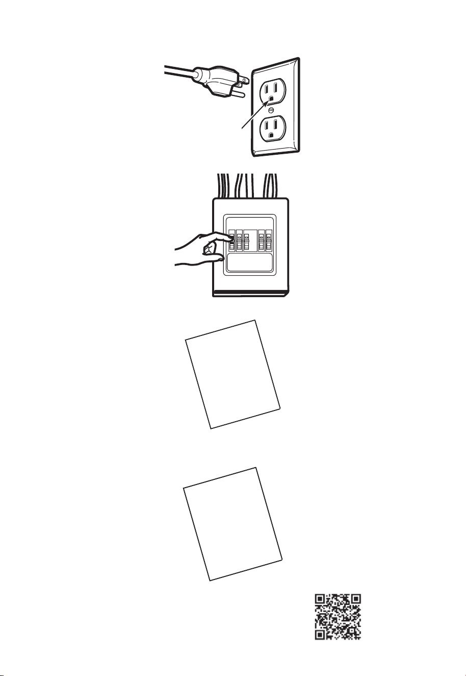
46
4. Enchufe el cable de alimentación a un tomacorriente independiente y dedicado de 15
a 20 amperios.
Asegúrese de
que haya una
conexión a
tierra adecuada
antes de usarlo.
5. Reemplace el fusible de la vivienda o vuelva a encender el interruptor.
6. Lea el manual de USO Y CUIDADO.
USE & CARE
MANUAL
7. CONSERVE LAS INSTRUCCIONES DE INSTALACIÓN PARA EL USO DEL INSPECTOR
LOCAL.
INSTALLATION
INSTRUCTIONS
8. REGISTRE SU PRODUCTO EN LÍNEA.
Registro en:
www.midea.com/us/support/Product-registration
EE. UU.
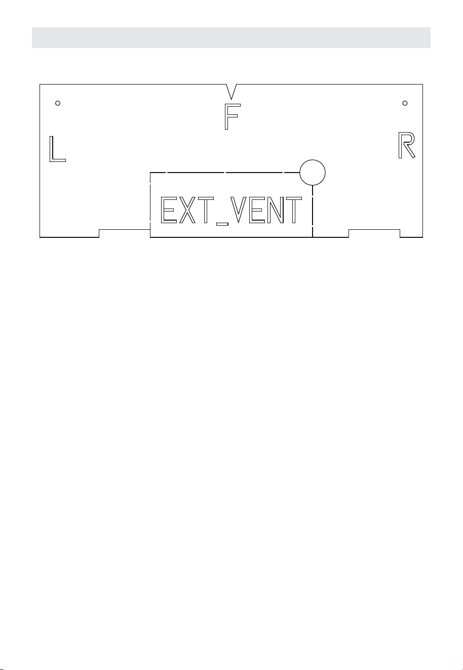
47
Información de la plantilla
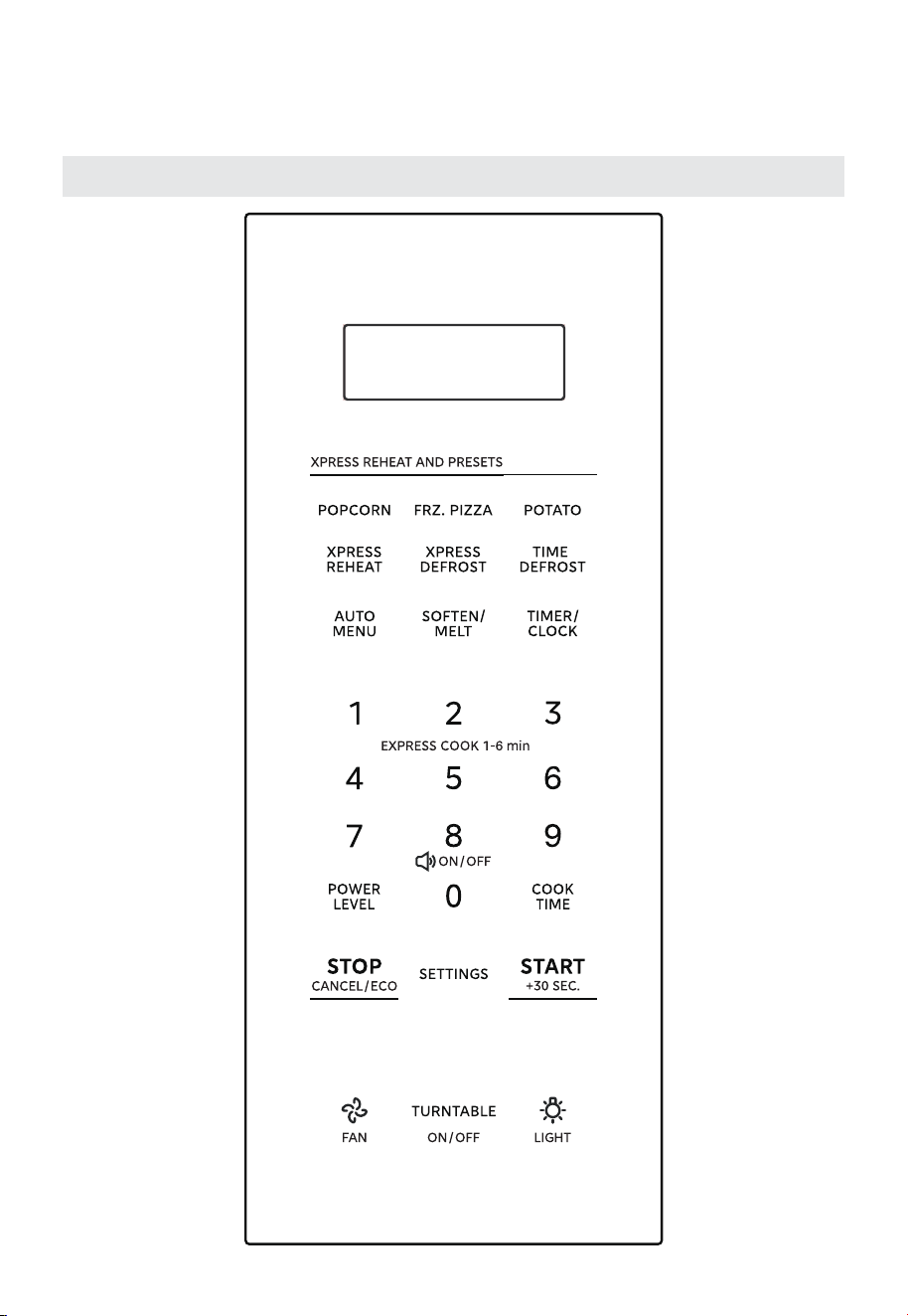
48
FUNCIONAMIENTO
Panel de control
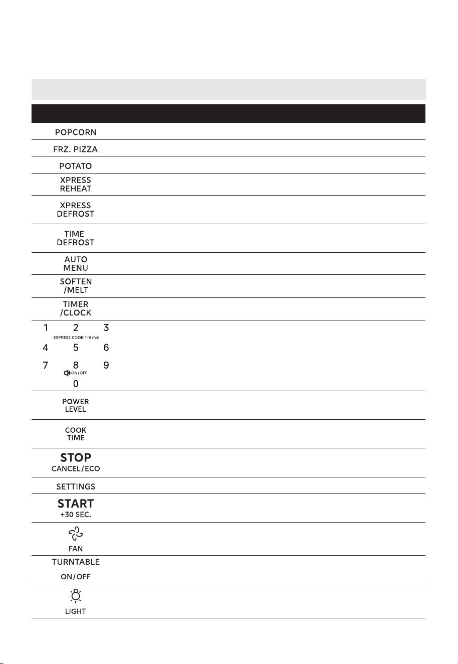
49
Descripción general de la función de los botones
Botón Descripción
Palomitas con programas preestablecidos por peso
Pizza congelada con programas preestablecidos por peso
Papa con programas preestablecidos por peso
Calienta rápidamente la comida según el peso seleccionado
Descongela rápidamente alimentos congelados según el peso
seleccionado
Descongela rápidamente alimentos congelados según el
tiempo seleccionado
Menú automático con programas preestablecidos por peso
Ablanda o derrite alimentos según el peso seleccionado
Ajusta el temporizador de cocción / Ajusta el reloj
Utilice las teclas numéricas para ingresar valores
personalizados / Presione los números "1-6" para iniciar la
cocción rápida de 1 a 6 minutos /
Utilice el número "8" para ingresar a la configuración del
modo de silencio
Establece el nivel de potencia para el funcionamiento del
microondas
Establece el nivel de potencia para el funcionamiento del
microondas
Pausa la cocción activa / Cancela la operación actual /
Función Eco
Establece la preferencia del usuario
Iniciar cocción rápida durante 30 segundos / Confirmar
entrada / Iniciar operación / Añadir 30 segundos
Configure la ventilación en alta / baja / apagada
Activa o desactiva el plato giratorio
Enciende o apaga la luz
FUNCIONAMIENTO
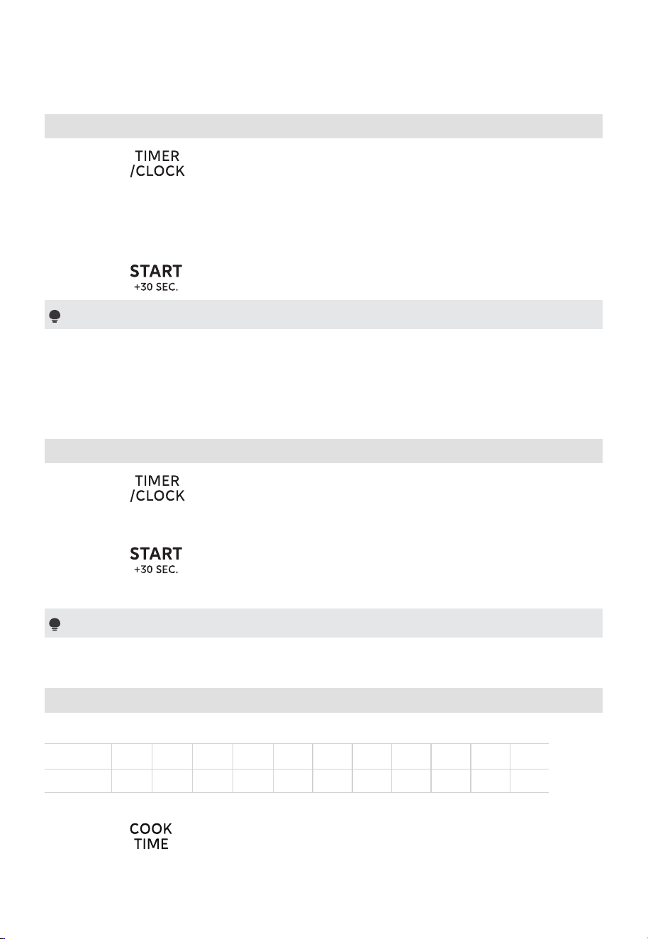
50
FUNCIONAMIENTO
1. Configuración del reloj
(1) Presione dos veces; el reloj o "12:00" parpadeará.
(Al encender el aparato por primera vez, "12:00" parpadeará, omita este
paso).
(2) Presione los botones numéricos para ingresar el tiempo.
Ejemplo: Para configurar el reloj a las 12:10, presione sucesivamente "1, 2, 1, 0".
(3) Presione para confirmar. El reloj está configurado.
Notas
(1) El reloj se visualiza en el formato de 12 horas. Para restablecer el reloj, repita
los pasos 1 a 3.
(2) Al encender el aparato, si no se realiza ninguna operación dentro de
5minutos, la pantalla se apagará.
2. Configuración del temporizador de cocina
(1) Presione una vez y, a continuación, se mostrará ":0".
(2) Presione los botones numéricos para establecer el tiempo deseado. El valor
máximo de tiempo es "99:99".
(3) Presione para confirmar. El temporizador comienza la cuenta
regresiva.
Nota
El temporizador de cocina es un temporizador.
3. Cocción por microondas
Hay 11 niveles de potencia disponibles.
Potencia 100% 90% 80% 70% 60% 50% 40% 30% 20% 10% 0%
Pantalla P-HI P-90 P-80 P-70 P-60 P-50 P-40 P-30 P-20 P-10 P-0
Método 1:
(1) Presione una vez y, a continuación, se mostrará ":0".
(2) Presione los botones numéricos para establecer el tiempo de cocción. El valor
máximo de tiempo es "99:99".
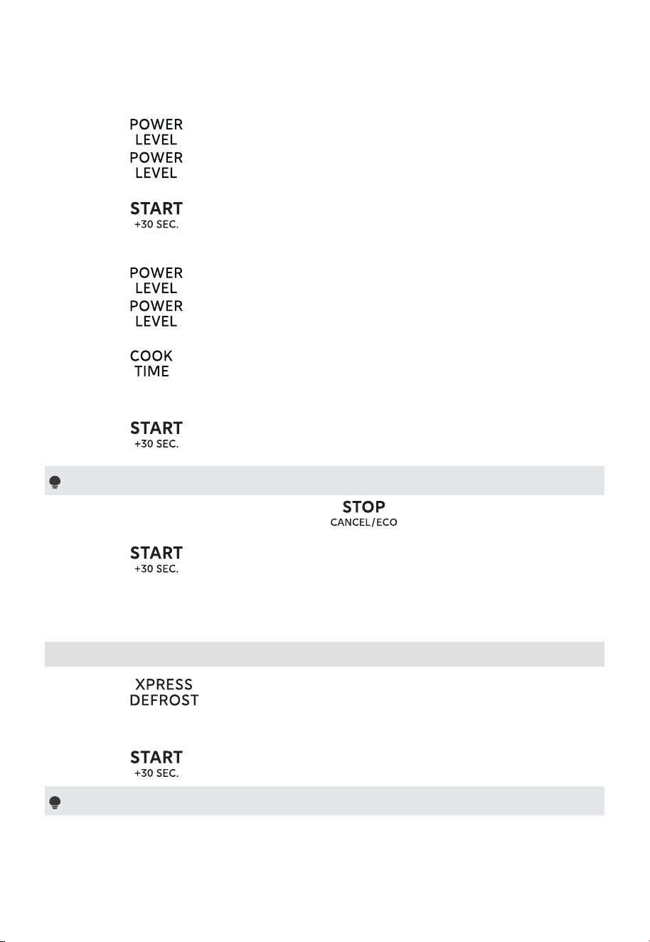
51
FUNCIONAMIENTO
(3) Presione una vez y, a continuación, aparecerá "P-HI".
(4) Presione repetidamente o presione los botones numéricos para
ajustar el nivel de potencia. Hay 11 niveles de potencia disponibles.
(5) Presione para iniciar la cocción.
Método 2:
(1) Presione una vez y, a continuación, aparecerá "P-HI".
(2) Presione repetidamente o presione los botones numéricos para
ajustar el nivel de potencia. Hay 11 niveles de potencia disponibles.
(3) Presione una vez y, a continuación, se mostrará ":0".
(4) Presione los botones numéricos para establecer el tiempo de cocción. El valor
máximo de tiempo es "99:99".
(5) Presione para iniciar la cocción.
Notas
(1) Si abre la puerta del horno o presiona durante el funcionamiento
se interrumpirá el modo actual. Cierre la puerta del horno y, a continuación,
presione
para reanudar la operación.
(2) Si selecciona "P-0", el horno funcionará con el ventilador sin potencia. Puede
utilizar este nivel para eliminar el olor del horno.
4. Descongelación rápida
(1) Presione una vez y, a continuación, se mostrará "0.0 lb".
(2) Presione los botones numéricos para establecer el peso de la comida. El
rango de peso es de 0.2 a 4.4 lbs.
(3) Presione para iniciar la descongelación.
Nota
La alarma sonará para recordarle que debe dar vuelta a los alimentos durante
la descongelación. Si no se realiza ninguna operación, el horno continuará
funcionando.
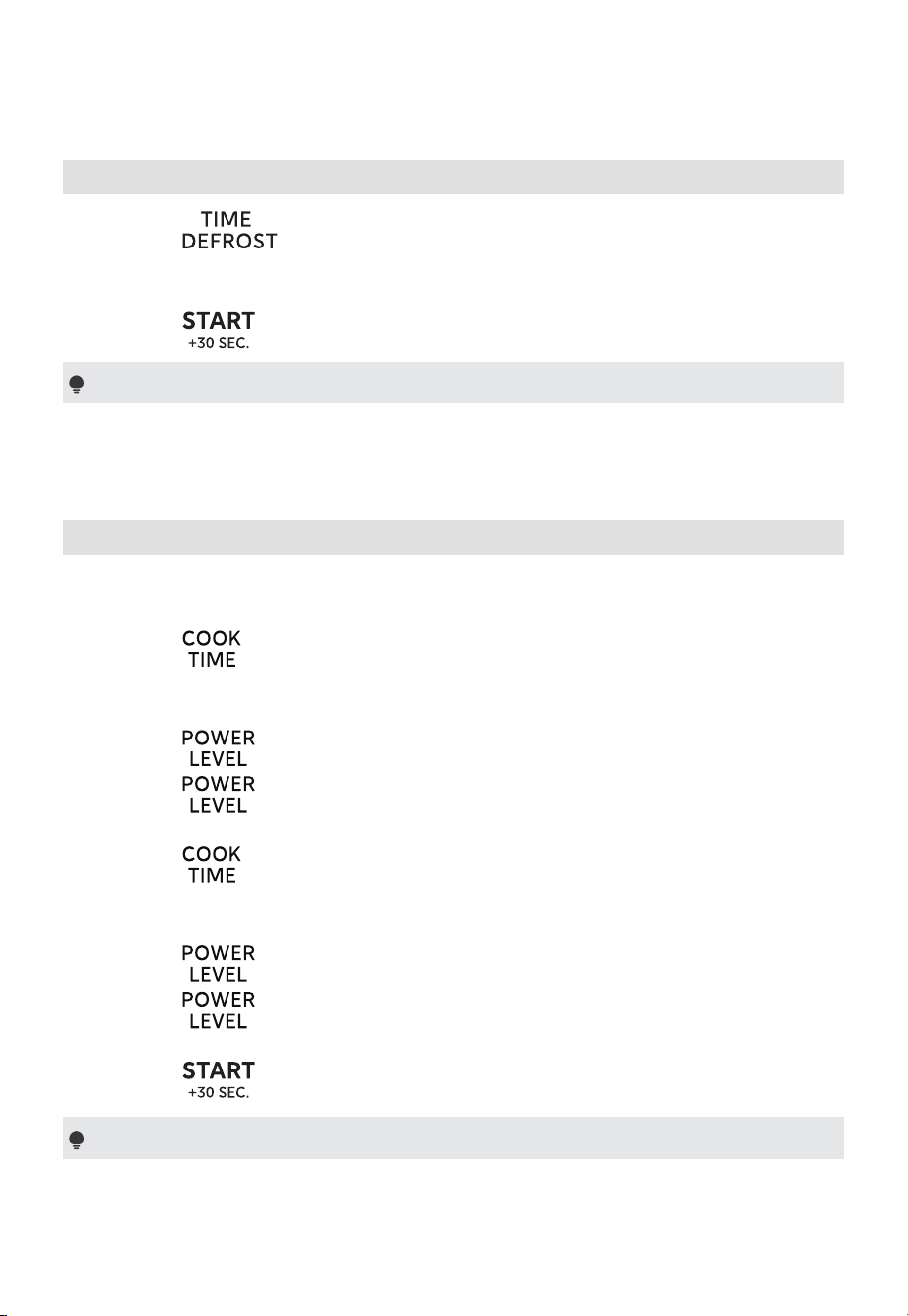
52
FUNCIONAMIENTO
5. Descongelar por tiempo
(1) Presione una vez y, a continuación, se mostrará "0:00".
(2) Presione los botones numéricos para establecer el tiempo de descongelación.
El valor máximo de tiempo es "99:99".
(3) Presione para iniciar la descongelación.
Nota
La alarma sonará para recordarle que debe dar vuelta a los alimentos durante
la descongelación. Si no se realiza ninguna operación, el horno continuará
funcionando.
6. Cocción en múltiples etapas
Ejemplo: Cocine con 80% de potencia del microondas durante 5 minutos y, a
continuación, cocine con 50% de potencia del microondas durante 7 minutos.
(1) Presione una vez y, a continuación, se mostrará " :0".
(2) Presione los botones numéricos "5", "0" y "0" para establecer el tiempo de
cocción en 5 minutos.
(3) Presione una vez y, a continuación, aparecerá "P-HI".
(4) Presione repetidamente o presione el botón numérico "8" para
establecer el nivel de potencia en "P-80".
(5) Presione una vez y, a continuación, se mostrará " :0".
(6) Presione los botones numéricos "7", "0" y "0" para establecer el tiempo de
cocción en 7 minutos.
(7) Presione una vez y, a continuación, aparecerá "P-HI".
(8) Presione repetidamente o presione el botón numérico "5" para ajustar
el nivel de potencia a "P-50".
(9) Presione para iniciar la cocción.
Nota
(1) Se pueden establecer como máximo dos etapas de cocción en el microondas.
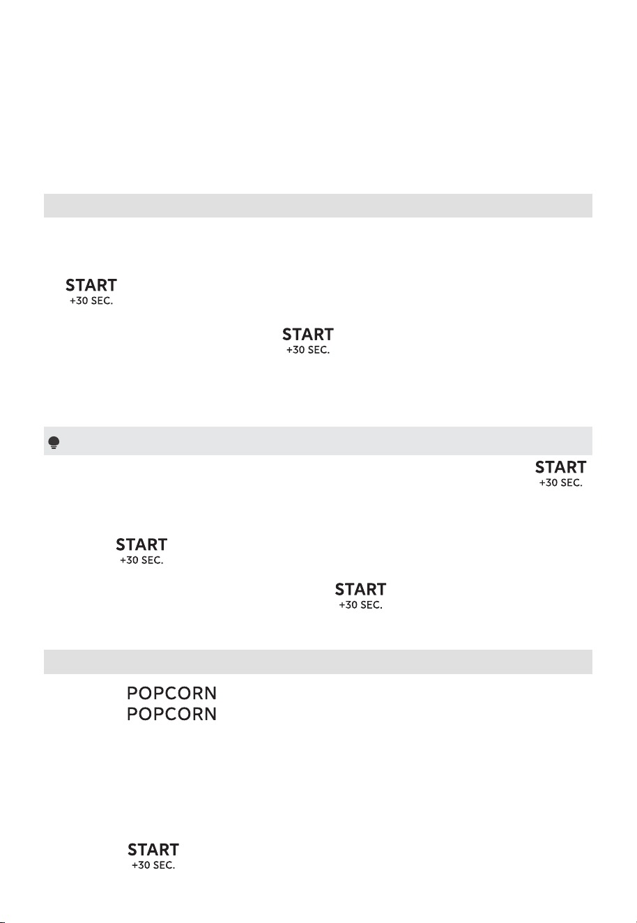
53
FUNCIONAMIENTO
(2) El método de configuración de la cocción en la segunda etapa debe coincidir
con el de la primera etapa. Si el tiempo de cocción se establece primero en la
primera etapa, también debe establecerse primero en la segunda etapa.
7. Cocción rápida
(1) En el modo de espera, al presionar los botones numéricos 1 a 6, le permitirá
seleccionar rápidamente el tiempo de cocción de 1 a 6 minutos. La cocción
comenzará automáticamente en 2 segundos. A continuación, puede presionar
para aumentar el tiempo de cocción. El valor máximo de tiempo es
"99:99".
(2) En el modo de espera, presione para cocinar los alimentos con un
nivel de potencia del 100% durante 30 segundos. Cada pulsación del mismo
botón puede aumentar el tiempo de cocción en 30 segundos, con un valor
máximo de tiempo de "99:99".
Nota
(1) En el estado de cocción por microondas, cada pulsación adicional en
puede aumentar el tiempo de cocción en 30 segundos (excepto para la
descongelación y el menú automático).
(2) Se mostrará "Food" si no se selecciona ninguno de los botones numéricos del
1 al 6 o
dentro de los 5 minutos posteriores a colocar la comida en el
horno. Abra y luego vuelva a cerrar la puerta para eliminar el mensaje "Food"
de la pantalla. A continuación, presione
para iniciar la cocción.
8. Popcorn
(1) Presione una vez y, a continuación, se mostrará "3.3 oz".
(2) Presione repetidamente o presione el botón numérico "1", "2" o
"3" para establecer el peso de la comida. Están disponibles "3.3 oz", "3.0 oz" y
"1.75 oz".
Ejemplo: Presione "2" una vez y, a continuación, se mostrará "3.0 oz".
"1": 3.3 oz
"2": 3.0 oz
"3": 1.75 oz
(3) Presione para iniciar la cocción.
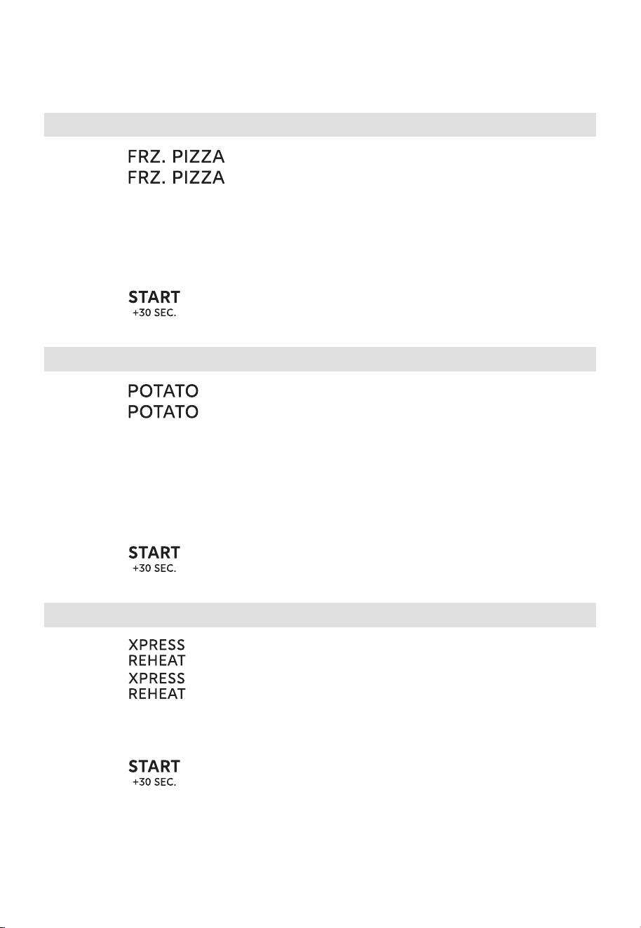
54
FUNCIONAMIENTO
9. Frz.Pizza
(1) Presione una vez y, a continuación, se mostrará "6 oz".
(2) Presione repetidamente o presione el botón numérico "1", "2" o
"3" para establecer el peso de la comida. Están disponibles "6 oz, 8 oz, 12 oz".
Ejemplo: Presione "2" una vez y, a continuación, se mostrará "8 oz".
"1": 6 oz
"2": 8 oz
"3": 12 oz
(3) Presione para iniciar la cocción.
10. Potato
(1) Presione una vez y, a continuación, se mostrará "1".
(2) Presione repetidamente o presione el botón numérico "1", "2", "3" o
"4" para establecer el peso de la comida. Están disponibles "1, 2, 3, 4".
Ejemplo: Presione "2" una vez y, a continuación, se mostrará "2".
"1": 1 papa
"2": 2 papas
"3": 3 papas
"4": 4 papas
(3) Presione para iniciar la cocción.
11. Xpress Reheat
(1) Presione una vez y, a continuación, se mostrará "RH-1".
(2) Presione repetidamente para seleccionar el tipo de alimento. Están
disponibles "RH-1, RH-2, RH-3, RH-4".
(3) Presione el botón numérico "1", "2", "3" o "4" para establecer el peso de la
comida.
(4) Presione para iniciar la cocción.
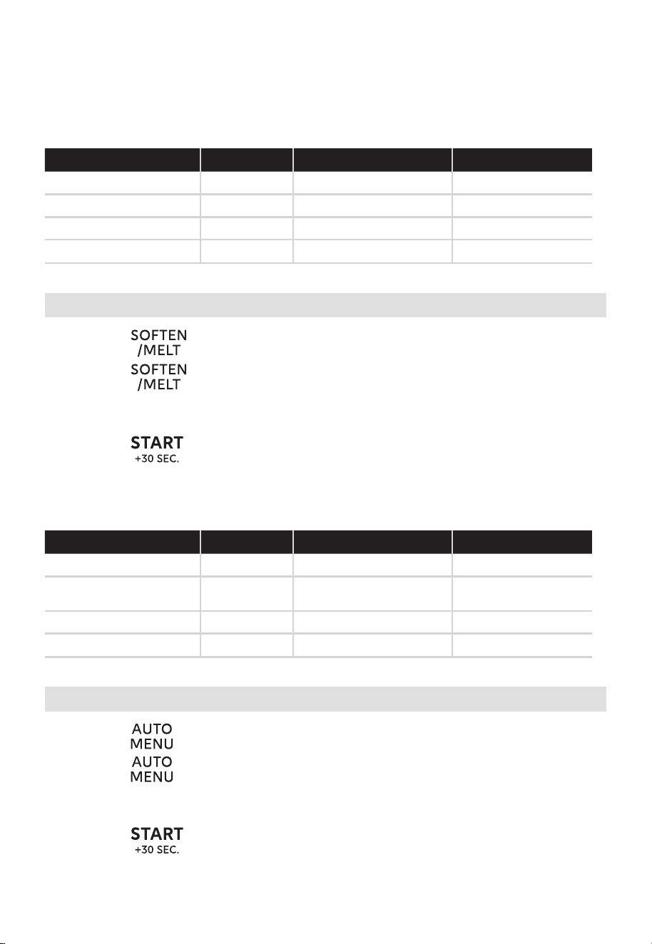
55
FUNCIONAMIENTO
Xpress Reheat Chart
Comida Pantalla Botón numérico Peso
Recalentar pizza RH-1 1, 2, 3, 4 1-4 porciones
Plato de cena RH-2 1, 2 8 oz, 16 oz
Recalentar pasta RH-3 1, 2 1-2 tazas
Recalentar arroz RH-4 1, 2 1-2 tazas
12. Soften/Melt
(1) Presione una vez y, a continuación, se mostrará "So-1".
(2) Presione repetidamente para seleccionar el tipo de alimento. "Están
disponibles So-1, So-2, So-3, So-4".
(3) Presione el botón numérico "1", "2" o "3" para establecer el peso de la comida.
(4) Presione para iniciar la cocción.
Tabla de ablandar/fundir
Comida Pantalla Botón numérico Peso
Ablandar helado So-1 1, 2 Pinta, 1.5 cuartos
Ablandar queso
crema
So-2 1, 2 3 oz, 8 oz
Derretir mantequilla So-3 1, 2 1-2 palitos
Derretir chocolate So-4 1, 2, 3 2 oz, 4 oz, 8 oz
13. Menú automático
(1) Presione una vez y, a continuación, aparecerá "A-01".
(2) Presione repetidamente para seleccionar el menú que desee. Los
6menús automáticos están disponibles.
(3) Presione los botones numéricos para establecer el peso de la comida.
(4) Presione para iniciar la cocción.
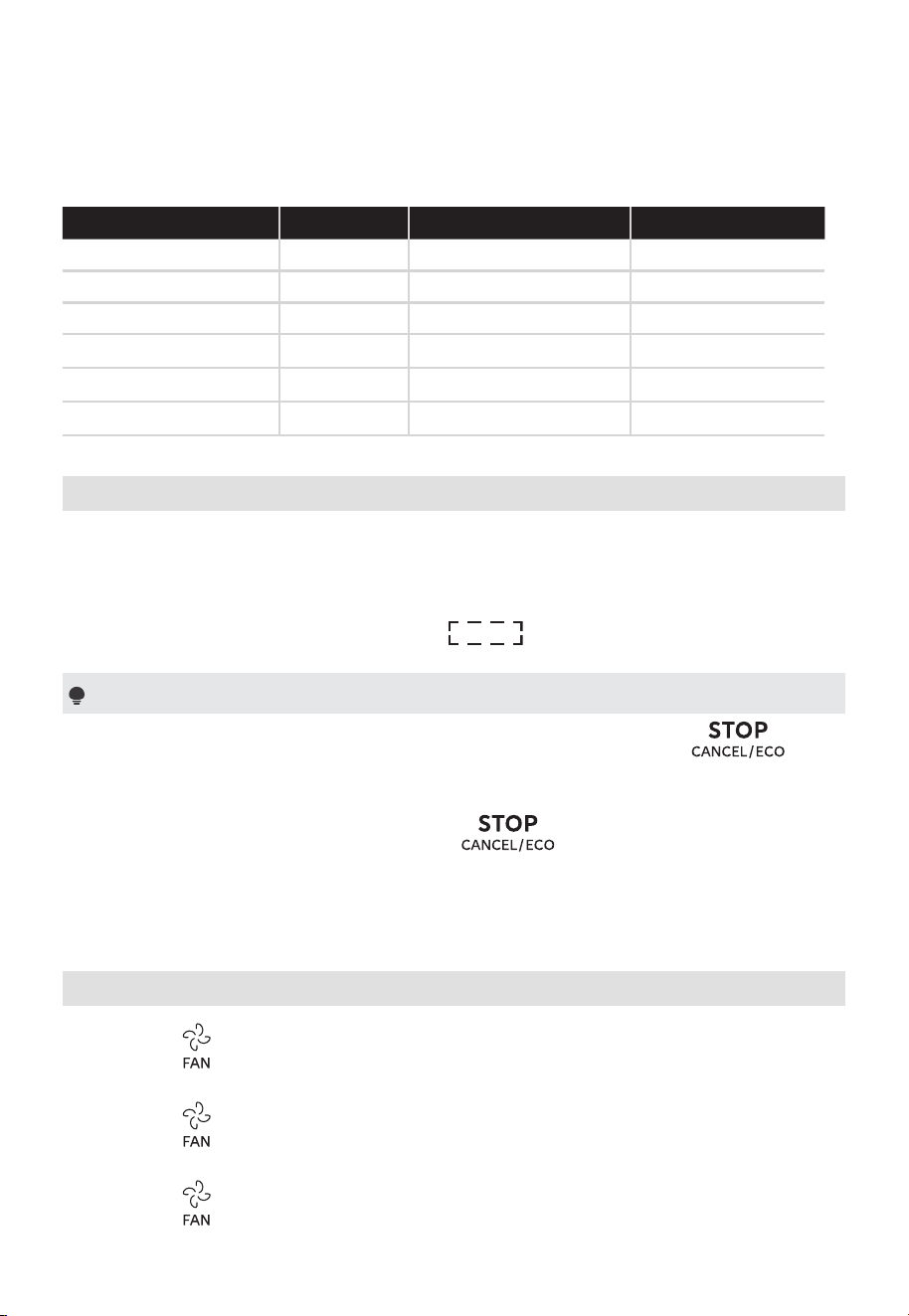
56
FUNCIONAMIENTO
Tabla del menú automático
Comida Pantalla Botón numérico Peso
Bebida A-01 1, 2, 3 1-3 tazas
Vegetales frescos A-02 1, 2, 3, 4 1 - 4 tazas
Verduras congeladas A-03 1, 2, 3, 4 1 - 4 tazas
Tocino A-04 1, 2, 3 1-3 rebanadas
Perros calientes A-05 1, 2, 3, 4, 5, 6 1-6 piezas
Sopa A-06 1, 2 1-2 tazas
14. Función de reinicio del plato giratorio
Puede utilizar esta función para reposicionar el plato giratorio a su posición
original en el horno microondas después de la cocción. De este modo, le resultará
más fácil retirar los alimentos del horno microondas. La función de reposición del
plato giratorio está activada de forma predeterminada. Durante el proceso de
reinicio del plato giratorio, se mostrará "
".
Notas
(1) Esta función es válida para una cocción completa. Si presiona o
abre y luego cierra la puerta del horno durante la cocción, esta función no
será válida.
(2) Si abre la puerta del horno o presiona durante el proceso de reinicio
del plato giratorio, el horno pasará al modo de espera.
(3) Si el tiempo de cocción es de 5 minutos, la precisión del plato giratorio es de
30 grados.
15. Configuración del ventilador: Alto/Bajo/Apagado
(1) Presione una vez para configurar e ventilador en alto y, a continuación, se
mostrará el icono "VENT HI".
(2) Presione dos veces para configurar el ventilador en bajo y se mostrará el
icono "VENT LOW".
(3) Presione tres veces para configurar el ventilador en apagado y, a
continuación, se mostrará "oFF".
57
FUNCIONAMIENTO
16. Configuración de encendido o apagado de la luz
una vez para encender la luz y, a continuación, se mostrará "on".
dos veces para apagar la luz y, a continuación, se mostrará
(1) Presione
(2) Presione
"
oFF".
17. Configuración de activación o desactivación del plato giratorio
Para desactivar el plato giratorio:
En modo de espera, presione
una vez y, a continuación, se mostrará
"OFF".
Inicie la cocción dentro de 5 minutos y el plato giratorio no funcionará (excepto
para el menú automático y la descongelación).
Para activar el plato giratorio:
En modo de espera, presione
una vez y, a continuación, se mostrará
"on".
18. Función de consulta
(1) Si el reloj ha sido configurado y solo está funcionando el temporizador de
cocina, la hora actual se mostrará durante dos segundos al presionar
.
(2) Si se ha configurado el temporizador de cocina, el tiempo restante actual se
mostrará durante dos segundos al presionar
en el estado de cocción.
(3) En el estado de cocción con microondas, presione para ver el nivel de
potencia. Se mostrará durante dos segundos.
19. Función ECO
Para ingresar al modo ECO:
En el modo de espera, presione
una vez. La pantalla se apagará.
Para cancelar el modo ECO:
En el modo ECO, presione cualquier botón o abra y cierre la puerta para
cancelarlo.
58
20. Modo de silencio
Para activar el modo de silencio:
En el modo de espera, mantenga presionado
durante 3 segundos. Se
mostrará en la pantalla "oFF". Al presionar los botones, no se emitirá ningún
sonido.
Para desactivar el modo de silencio:
En el modo de silencio, mantenga presionado durante 3 segundos. Se
mostrará "on".
21. Preferencias del usuario
21.1 Función de bloqueo para niños
Puede utilizar esta función para desactivar los botones de la pantalla y evitar que
los niños enciendan el horno accidentalmente.
Para activar el bloqueo:
(1) En modo de espera, presione una vez, se mostrará "SE-1".
(2) Presione para confirmar y, a continuación, se mostrarán los iconos
"on" y "LOCK".
(3) Presione nuevamente para activar el bloqueo.
Para desactivar el bloqueo:
(1) En modo de espera, presione
una vez, se mostrará "oFF".
(2) Presione para confirmar y, a continuación, desaparecerán los iconos
"oFF" y "LOCK".
21.2 Configuración de activación o desactivación del volumen
(1) En modo de espera, presione dos veces, se mostrará "SE-2".
(2) Presione y, a continuación, se mostrarán en bucle "Lo", "nor", "HI" y
"oFF".
(3) Presione para confirmar su selección cuando se muestre el volumen
correspondiente.
FUNCIONAMIENTO
59
FUNCIONAMIENTO
21.3 Configuración de la unidad de peso (Lbs/Kg)
(1) En modo de espera, presione tres veces, se mostrará "SE-3".
(2) Presione y, a continuación, se mostrarán en bucle "SE-3 lb" y "SE-
3kg".
(3) Presione para confirmar su selección cuando se muestre la unidad de
peso correspondiente.
21.4 Configuración de activación o desactivación de la función Demo
(1) En modo de espera, presione cuatro veces; se mostrará "SE-4".
(2) Presione y, a continuación, se mostrarán en bucle "on" y "oFF".
(3) Presione para confirmar su selección cuando se muestre la opción
correspondiente.
Nota
Si no se corta la energía, la configuración se guardará todo el tiempo.
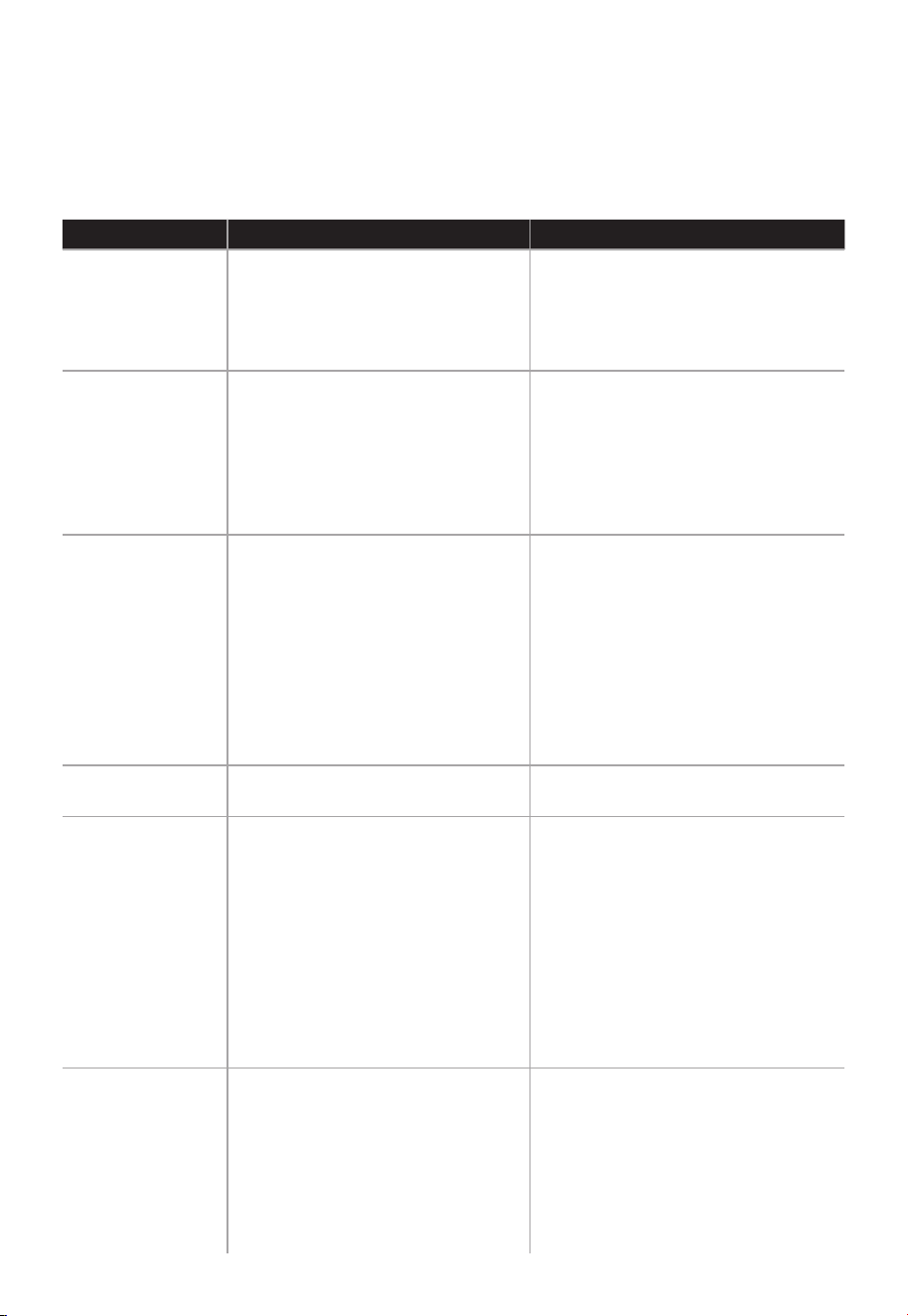
60
RESOLUCIÓN DE PROBLEMAS
Verifique el problema utilizando la siguiente tabla y pruebe las soluciones para cada
problema. Si el horno microondas aún no funciona correctamente, póngase en contacto
con el centro de servicio autorizado más cercano.
PROBLEMA POSIBLE CAUSA POSIBLE SOLUCIÓN
El horno no
enciende
a. El cable eléctrico del horno
no está enchufado.
b. La puerta está abierta.
c. Se estableció una operación
incorrecta.
a. Conecte el horno al
tomacorriente.
b. Cierre la puerta e inténtelo de
nuevo.
c. Verifique las instrucciones.
Arcos eléctricos
y chispas
a. Se utilizaron materiales
no aptos para horno
microondas.
b. El horno funciona cuando
está vacío.
c. Quedan restos de comida en
el interior del horno.
a. Utilice únicamente utensilios
de cocina aptos para
microondas.
b. No utilice el horno microondas
vacío.
c. Limpie el interior del horno
con una toalla húmeda.
Alimentos
cocidos de
forma desigual
a. Se utilizaron materiales
no aptos para horno
microondas.
b. La comida no se descongela
completamente.
c. El tiempo de cocción y el
nivel de potencia no son
adecuados.
d. La comida no se da vuelta ni
se revuelve.
a. Utilice únicamente utensilios
de cocina aptos para
microondas.
b. Descongele completamente
los alimentos.
c. Utilice el tiempo de cocción
y el nivel de potencia
adecuados.
d. Voltee o revuelva los
alimentos.
Alimentos
sobrecocidos
El tiempo de cocción y el nivel
de potencia no son adecuados.
Utilice el tiempo de cocción y el
nivel de potencia adecuados.
Alimentos mal
cocidos
a. Se utilizaron materiales
no aptos para horno
microondas.
b. La comida no se descongela
completamente.
c. Los puertos de ventilación
del horno están obstruidos.
d. El tiempo de cocción y el
nivel de potencia no son
adecuados.
a. Utilice únicamente utensilios
de cocina aptos para
microondas.
b. Descongele completamente
los alimentos.
c. Verifique que las salidas de
ventilación del horno no estén
obstruidas.
d. Utilice el tiempo de cocción
y el nivel de potencia
adecuados.
Descongelación
incorrecta
a. Se utilizaron materiales
no aptos para horno
microondas.
b. El tiempo de cocción y el
nivel de potencia no son
adecuados.
c. La comida no se da vuelta ni
se revuelve.
a. Utilice únicamente utensilios
de cocina aptos para
microondas.
b. Utilice el tiempo de cocción
y el nivel de potencia
adecuados.
c. Voltee o revuelva los
alimentos.
61
MARCAS REGISTRADAS,
DERECHOS DE AUTOR Y
DECLARACIÓN LEGAL
El logotipo , las marcas denominativas, el nombre comercial, la imagen
comercial y todas las versiones de los mismos son activos valiosos de Midea Group y
sus filiales ("Midea"), de las que Midea posee marcas comerciales, derechos de autor
y otros derechos de propiedad intelectual, y todo el fondo de comercio derivado del
uso de cualquier parte de una marca comercial de Midea. El uso de la marca Midea con
fines comerciales sin el consentimiento previo por escrito de Midea puede constituir una
infracción de la marca o una competencia desleal en violación de las leyes pertinentes.
Este manual es creación de Midea y Midea se reserva todos los derechos de autor
del mismo. Ninguna entidad o individuo puede usar, duplicar, modificar, distribuir en
su totalidad o en parte este manual, o agrupar o vender con otros productos sin el
consentimiento previo por escrito de Midea.
Todas las funciones e instrucciones descritas han sido actualizadas al momento de
imprimir este manual. Sin embargo, el producto real puede variar debido a funciones y
diseños mejorados.
62
ELIMINACIÓN Y RECICLAJE
Instrucciones importantes para el medio ambiente
Cumplimiento de la Directiva RAEE y eliminación del producto usado:
Este producto cumple con la Directiva RAEE de la UE (2012/19/UE). Este producto lleva
un símbolo de clasificación para residuos de aparatos eléctricos y electrónicos (RAEE).
Este símbolo indica que este producto no debe desecharse con
otros residuos domésticos al final de su vida útil. El aparato
usado debe devolverse a un punto de recogida oficial para el
reciclaje de aparatos eléctricos y electrónicos. Para encontrar
estos sistemas de recogida, póngase en contacto con las
autoridades locales o con la tienda donde adquirió el producto.
Cada hogar desempeña un papel importante en la recuperación
y el reciclaje de aparatos usados. La eliminación adecuada de
los aparatos utilizados ayuda a prevenir posibles consecuencias
negativas para el medio ambiente y la salud humana.
Cumplimiento de la Directiva RoHS
El producto que ha adquirido cumple con la Directiva RoHS de la UE (2011/65/UE). No
contiene materiales nocivos ni prohibidos especificados en la Directiva.
Información de embalaje
Los materiales de embalaje del producto están fabricados con
materiales reciclables de acuerdo con nuestra Normativa Nacional
de Medio Ambiente. No deseche los materiales de embalaje
junto con los residuos domésticos o de otro tipo. Llévelos a los
puntos de recogida de material de embalaje designados por las
autoridades locales.

63
AVISO DE PROTECCIÓN DE DATOS
Para la prestación de los servicios acordados con el cliente,
nos comprometemos a cumplir sin restricciones con todas las estipulaciones de la ley de
protección de datos aplicable, en conformidad con los países acordados dentro de los
cuales se prestarán los servicios al cliente, así como, cuando corresponda, el Reglamento
General de Protección de Datos de la UE (GDPR).
En general, nuestro procesamiento de datos es para cumplir con nuestra obligación
bajo contrato con usted y por razones de seguridad del producto, para salvaguardar
sus derechos en relación con las preguntas de garantía y registro del producto. En
algunos casos, pero solamente si se garantiza la protección de datos adecuada, los datos
personales pueden transferirse a destinatarios ubicados fuera del Espacio Económico
Europeo.
Si desea, puede solicitar más información. Puede ponerse en contacto con nuestro
responsable de protección de datos a través de [email protected]. Para ejercer sus
derechos, como el derecho a oponerse al tratamiento de sus datos personales con fines
de marketing directo, póngase en contacto con nosotros a través de
[email protected]om. Para obtener más información, siga el código QR.

GARANTÍA LIMITADA DE DOS AÑO
Este producto tiene una garantía que establece que estará libre de defectos de material y mano
de obra durante un período de dos año a partir de la fecha de compra. Esta garantía es válida
para el comprador al detal original a partir de la fecha de la compra al detal inicial y no es
transferible. Guarde su factura de compra original.
IMPORTANTE:
1. Esta garantía no cubre daños resultantes de accidentes, uso indebido o abuso, falta de cuidado
razonable, instalación de accesorios no proporcionados con el producto, pérdida de piezas o
someter el aparato a un voltaje distinto al especicado. (Lea atentamente las instrucciones ).
2. Esta garantía queda anulada si este producto se llega a utilizar para nes distintos de los
domésticos.
3. Esta garantía queda anulada si este producto se llega a utilizar fuera de los Estados Unidos.
Si requiere servicio durante el período de garantía, empaque adecuadamente el producto. Se
recomienda utilizar la caja y los materiales de embalaje originales.
Si requiere asistencia adicional, póngase en contacto con el servicio de atención al cliente en:
855-204-5313
Midea America Corp. renuncia expresamente a toda responsabilidad por daños consecuentes o
pérdidas incidentales causadas por el uso del electrodoméstico. Algunos estados no permiten
esta exclusión o limitación de pérdidas incidentales o consecuentes, por lo que es posible que el
descargo de responsabilidad anterior no se aplique a usted. Esta garantía le otorga derechos
legales especícos, además usted también puede tener otros derechos que varían de un estado a
otro.
El número de serie se puede encontrar en la parte trasera. Le sugerimos que anote el número de
serie de su unidad en el espacio siguiente para futuras referencias
Número de Modelo:
Número de Serie:
No es obligatorio registrar el producto. No completar y devolver la tarjeta o el formulario no
disminuye los derechos de garantía del consumidor.
GUARDE ESTA INFORMACIÓN
Fabricado en China
6
4
© Midea 2026. Todos los derechos reservados