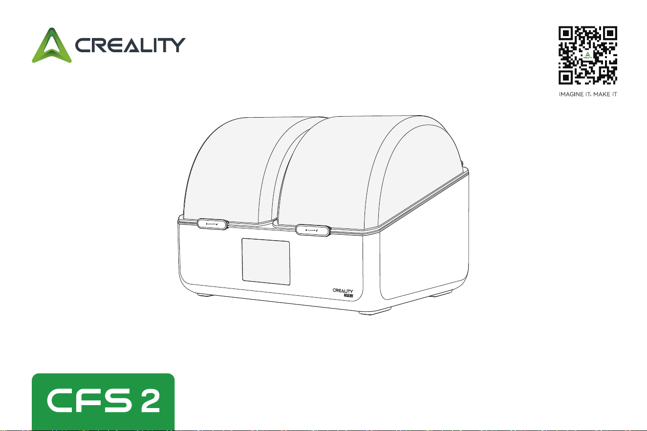
User Manual
CFS 2 Filament Management System
V 1.0_EN
Thank you for choosing Creality products. This quick guide introduces the steps for unboxing, installation, and debugging. Please read
it carefully before use.
For more detailed instructions, unboxing videos, and after-sales seice tutorials, please visit the Creality Wiki platform.
The Creality team is always ready to provide you with quality seice. If you encounter any problems during use, please contact us
through the phone number and email provided at the end of this quick guide.
Dear Users
https://wiki.creality.com
Comprehensive understanding of the new
product, immersive exploration of its features.
Detailed operation guides to help you get
staed eolessly.
Professional after-sales suppo platform
oering ecient solutions.
Creality ocial Wiki
Bought a product but
don't know how to use it?
Don't wor, all your
confusions will be resolved!
Creality Cloud – Your 3D
Printing Universe Awaits!
Discover the all-in-one 3D
printing platform designed
for all enthusiasts.
Creality Cloud App
https://www.crealitycloud.com
Access a vast libra of high-quality models.
Built-in cloud slicing and Print Settings make
printing easier than ever.
Control remotely and print with just one click,
anytime, anywhere.

Terms of Use
1. Do not attempt to use any operation methods not explicitly described in this manual to prevent accidental personal inju or propey damage;
2. Do not place this device among ammable or explosive materials, or near high-heat sources. Please place the device in a well-ventilated, cool, and
dust-free environment;
3. We highly recommend using the Creality Hyper plastic spool lament series. These materials have undergone extensive testing and can be used with
condence;
4. Do not use power cords other than the one provided with the device during installation. Ensure the power plug is plugged into a grounded 3-prong
electrical outlet;
5. To prevent clogging or jamming, do not use damp PVA or BVOH laments for printing;
6. To prevent spool jamming and eliminate safety hazards during the ding process, do not use cardboard spools;
7. In ding mode, the internal temperature of the device can reach up to 85°C. Ceain contact zones may become extremely hot. Do not open the chamber
door or maintain prolonged contact with internal components while the device is running;
8. The device generates heat during operation. Please ensure adequate surrounding ventilation and avoid covering the unit or placing it near ammable
items;
9. After prolonged operation, allow the device to cool down completely before peorming any maintenance or moving it;
10. Key components of this device are constructed from UL94V-0 rated ame-retardant materials; however, the device itself is not reproof. Do not
operate the device under extreme conditions;
11. Users must strictly comply with the relevant laws and regulations of the count or region where the device is located, adhere to professional ethics,
and fulll safety obligations. It is strictly prohibited to use our products or device for any illegal purposes.The company assumes no legal liability arising
from any violations.
12.Tip: Do not plug in or unplug wires on a charged basis.
13.Creality places the highest priority on the protection of human life and safety. By using our products or seices, you represent and warrant that the
products or seices acquired will not be used, directly or indirectly, for any purpose that may endanger the health or safety of individuals. This includes,
without limitation, the design, development, manufacture, or distribution of weapons or weapon-related components.
14. The full text of the EU Declaration of Conformity is available at the following internet address https://wiki.creality.com/en/euro-compliance
15. Hereby, SHENZHEN CREALITY 3D TECHNOLOGY CO., LTD declares that the radio equipment type is in compliance with Directive 2014/53/EU.

1. Device information
01-04
······················································································
01-01
·····················································································
1.1 Device oveiew
02-02
····················································································
1.2 Package contents
03-03
··················································································
1.3 Device specications
04-04
····················································································
1.4 Device dimensions
3. Instructions for use
09-12
···············································································
09-10
·····················································································
3.1 Display screen information
11-12
···············································································
3.2 Filament editing/reading
4. Tips and routine maintenance
13-14
········································································
13-13
···············································································
4.1 Replacing the internal PTFE tube
14-14
······································································
4.2 Cleaning debris from the 5-way tting
2. Unboxing setup
05-08
························································································
05-05
···········································································
2.1 Unboxing and placing the desiccant
06-08
·········································································
2.2 PTFE cable and PTFE tube connections
ContentsContentsContents
01
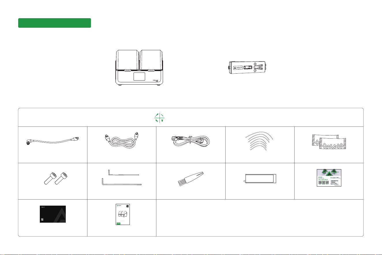
1.2 Package contents
(1) Filament buer
communication cable
(6) Hex socket screw ×2 (8) Cleaning brush
(2) Printer communication
cable
(3) Power cord
V2.4
(12) After-sales
seice card
(9) Buer double-sided
tape (spare)
(5) Desiccant ×2
Notice: The accessories listed above are for reference only.
Please refer to the actual product.
1. Device information1. Device information1. Device information
(2) Filament buer
(1) CFS 2 main unit
Accesso pack
(11) After-sales
seice card
(10) Creality Cloud card
(4) PTFE tube ×7
(including 5 spares)
After-Sales
Service Card
E-mail: [email protected]
Scan the code to know more
V2.2
V 1.0
Quick Installation Guide
EN ESDE FR PT-BR
IT
Pyc.
TR JP KR PL CN
(7) Hex key wrench
H2.0
H2.5
02
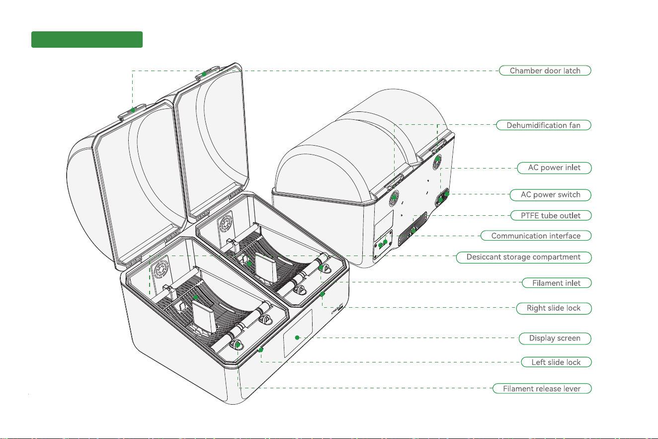
1.1 Device oveiew
1. Device oveiew1. Device oveiew1. Device oveiew

1.3 Device specications
1. Device information1. Device information1. Device information
General specifications
Model
CFS 2
Product dimensions
379*302*281.5mm
Net weight
5.0kg
Number of lament slots
2+2
Rated voltage
100-240V~, 50/60Hz
Power consumption
Max Power:330-1900W
Steady-state power:210-250W
Indicator lights
Integrated into the display screen
Display screen
LCD display
Diameter of lament suppoed
1.75 ± 0.05mm
Compatible lament spool specications
Diameter197-203mm,Thickness50-68mm(Cardboard spools not suppoed)
03
Suppoed lament types
PLA、PETG、ABS、PET、ASA、PA、PC、PP、Dried PVA、BVOH
PLA-CF、PLA-GF;PETG-CF、PETG-GF;ABS-FR...
Ding method
Dehumidication: suppos humidity-sensing dehumidication and automatic dehumidication during printing
Ding: suppos intelligently recommended ding temperature and time, max. temperature: 85°C.
Device daisy-chaining
≤4 units
Automatic lament refeed
Suppoed
Filament Tangle Detection
Suppoed
RFID lament
Suppos identication of Creality RFID lament
Filament remaining management
Remaining quantity recording, display, and status updates of lament suppoed
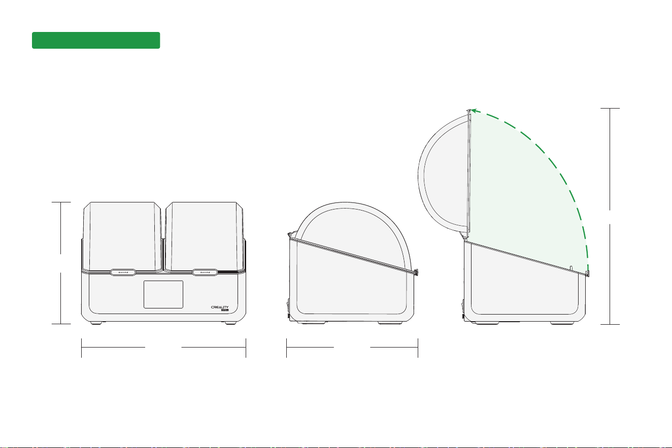
1.4 Device dimensions
04
105°
379mm
281.5mm
514mm
302mm
1. Device information1. Device information1. Device information
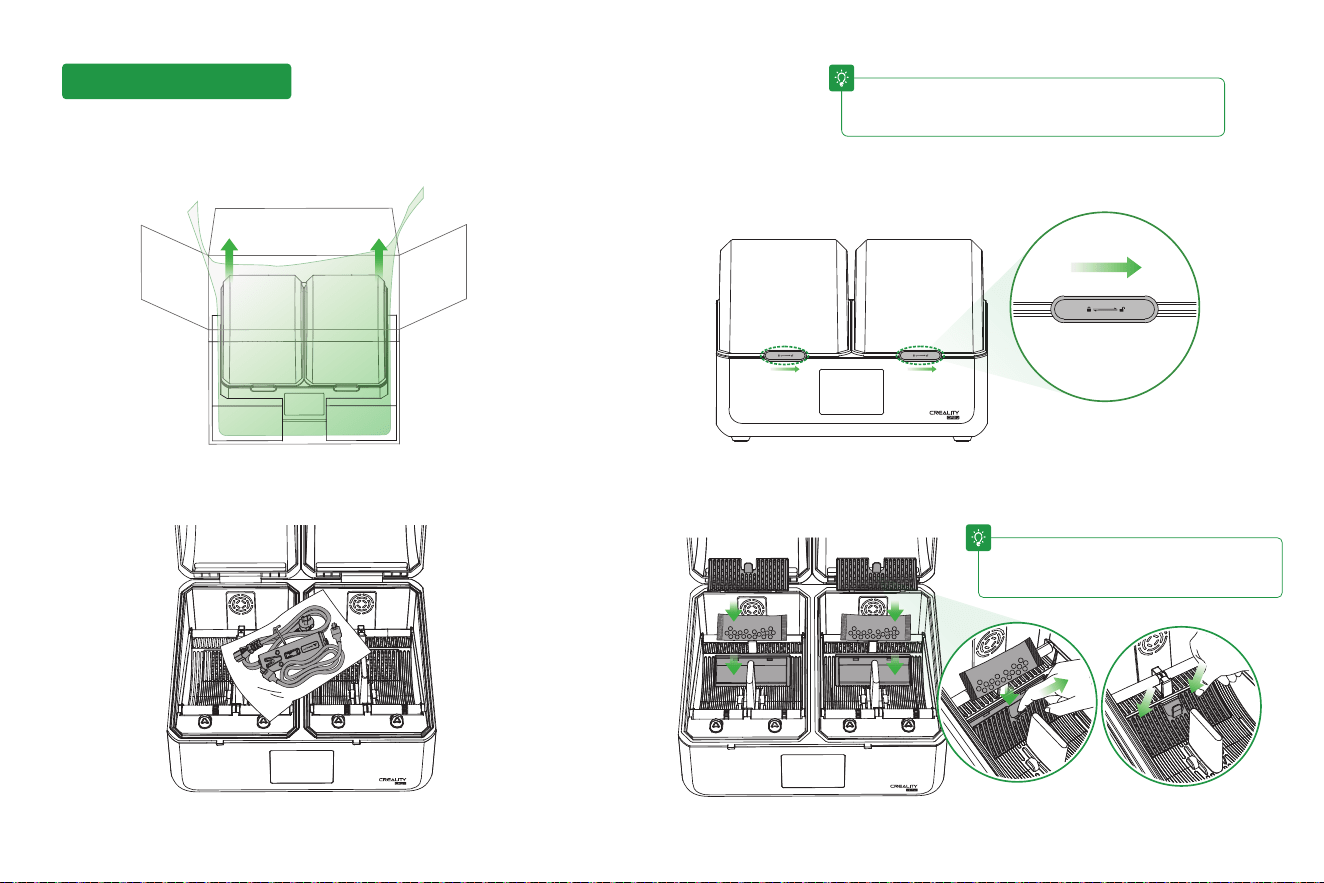
2.1 Unboxing and placing the desiccant
2. Unboxing setup
05
1.
Remove the CFS 2 main unit from its packaging.
2. Push the chamber door latch to unlock and open the top cover.
4. Open the desiccant storage compament lid, remove the desiccant from its
outer packaging, place it inside the compament, and then reattach the top cover.
干燥剂
3. Remove the pre-installed buer, power cord, and other accessories.
Color-indicating desiccant is used. It is
reusable and provides real-time feedback on
moisture absorption status. Do not ingest.
T
For compatible printer models that have already been
purchased, a printer rmware upgrade is required before
this product can be used.
T
06
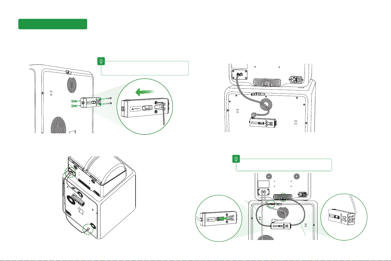
2.2 PTFE cable and PTFE tube connections
2. Unboxing setup
1. Remove the buer and its mounting screws, and secure the
buer to the rear of the printer.
2. Connect the sho communication cable between the CFS 2
main unit and the buer.
3. Connect the long communication cable between the CFS 2 main unit
and the printer.
4. Take a PTFE tube and rst connect the CFS 2 main unit to the buer
5-way tting, and connect the buer to the printer.
For the best experience, it is recommended
to mount the buer on the printer side.
T
Cut the tube to the appropriate length based on
device placement before use.
T
400mm
400mm
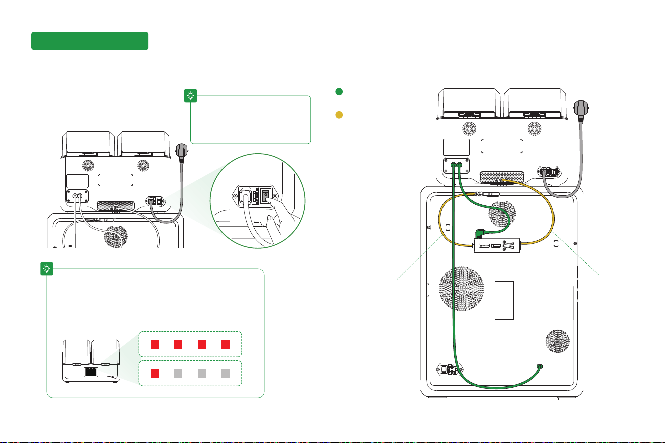
Green indicates the
communication cable.
Yellow indicates the
PTFE tube.
6. Single-unit connection diagram
07
5.
Inse the power cord into the CFS 2 main unit, connect it to an AC
power source, and turn on the power switch.
2. Unboxing setup
After the printer is powered on, the 4 red indicator lights on the
CFS 2 main unit display screen will illuminate simultaneously.
While the device is automatically establishing a connection with
the printer, the red indicator lights will ash in sequence. Once
the connection is established successfully, the indicator lights will
turn white.
T
The electric reheat dehumidica-
tion function requires AC power to
be turned on. When AC power is
o, the device can still be used for
normal printing.
T
400mm400mm
08
7.
Multi-unit daisy-chain diagram
2. Unboxing setup
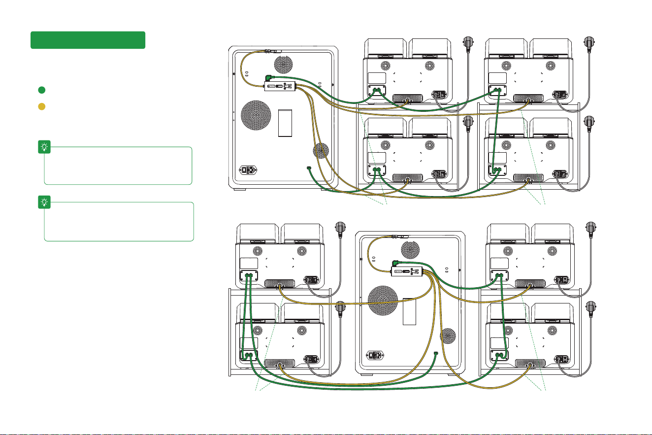
Green indicates the communication cable.
Yellow indicates the PTFE tube.
Simultaneous daisy-chaining of CFS Pro and
CFS to the same printer is suppoed. Actual
compatibility is subject to the ocial
rmware version.
T
The diagrams above show a typical
connection conguration. Actual connections
may va depending on device conguration
and usage requirements.
T
1200mm600mm
600mm800mm
09
a
c
d
g
e
f
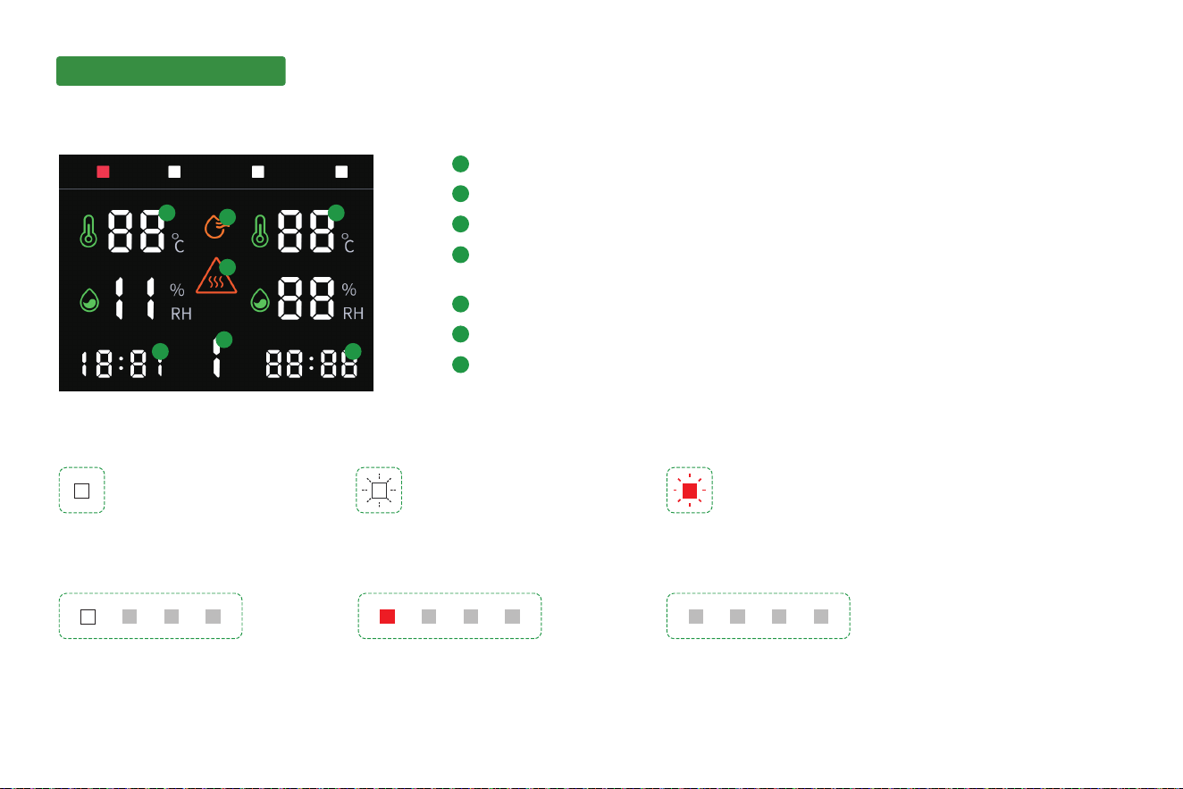
Real-time temperature and humidity in the left chamber;
a
Automatic dehumidication mode on;
c
Ding mode on; When the icon turns red, the suace of the top cover is hot.
Do not touch it for extended periods to avoid burns.
d
CFS 2 ID after connecting to the printer.
g
Remaining ding time after ding is enabled for the left and right chambers;
e
Automatic dehumidication duration;
f
Real-time temperature and humidity in the right chamber;
b
b
3.1 Display screen information
1.
The indicator light statuses are as follows:
Sequentially ashing white: All four lament
slots are empty.
Sequentially ashing red: A communication
connection is being established or a communication
error has occurred.
Solid white: Filament is loaded in
the slot and the unit is idle.
Breathing white: Filament is loaded in the slot and
the unit is busy, such as feeding lament or reading
RFID information.
Flashing red: An error occurs during printing or preloading.
White and red both o:
1.When lament is loaded in one slot, the LEDs of the other empty slots
remain o. This is normal.
2.When all four slots are empty, if the LED of any slot remains o, an error
has occurred and the slot should be checked.
3. Instructions for use3. Instructions for use3. Instructions for use
10
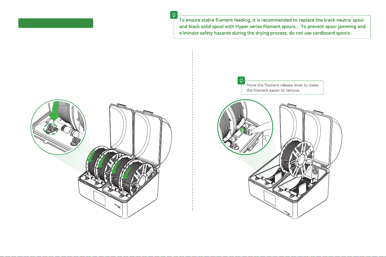
Loading lament: Place the lament into the CFS 2 and align the lament
tip with the slot opening. Gently push the lament in. When you feel the
lament being pulled in, release it. The lament will load automatically.
Unloading lament: First, make sure the lament has been retracted into the
CFS 2 main unit, then simply lift and pull out the lament. If the lament is
inside the extruder, rst tap "Unload" and follow the on-screen instructions.
Wait until the lament has been retracted into the CFS 2, then remove it.
T
2. Loading/Unloading lament:
T
3. Instructions for use3. Instructions for use3. Instructions for use
b
a
c
e
d
f
11
3.2 Filament editing/reading
1.
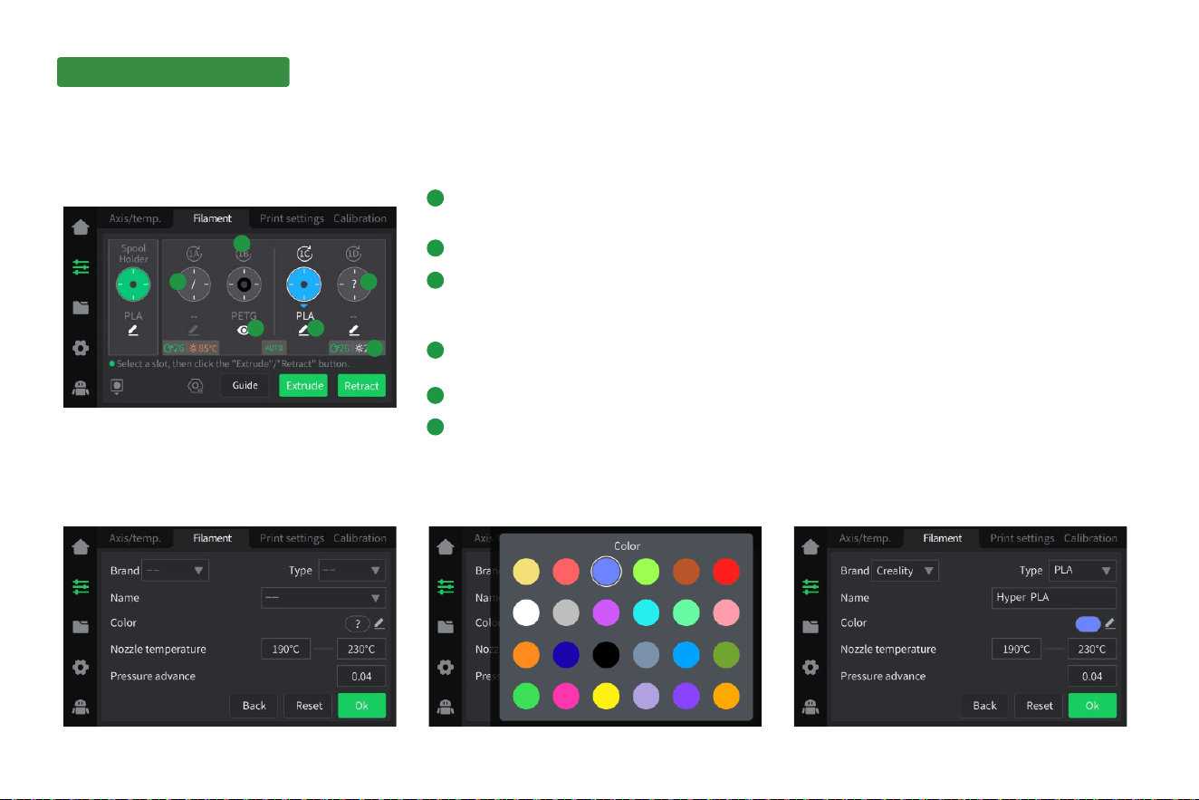
Filament management inteace oveiew: The lament management page is divided into two sections: the external holder [left] and CFS 2 [right].
2. Manually set parameters: lament brand, type, color, etc.
3. Instructions for use3. Instructions for use3. Instructions for use
Empty slot status. The slot is displayed as "/", and lament information cannot be edited in this state.
b
The Preload button. Tap it to read the lament information. Once the information is successfully read,
the remaining lament and lament color will be displayed.
a
RFID lament successfully read. Tap the eye icon to view the lament information. RFID lament can only be
viewed and cannot be edited. If RFID lament is currently loaded but you need to use non-RFID lament
next, tap the Preload button and wait for the reading to complete before tapping the Edit Filament button.
c
Non-RFID lament. Filament information can be edited.
e
RFID lament not detected. The lament is displayed as "?". Tap the Edit button to manually enter the
lament information.
d
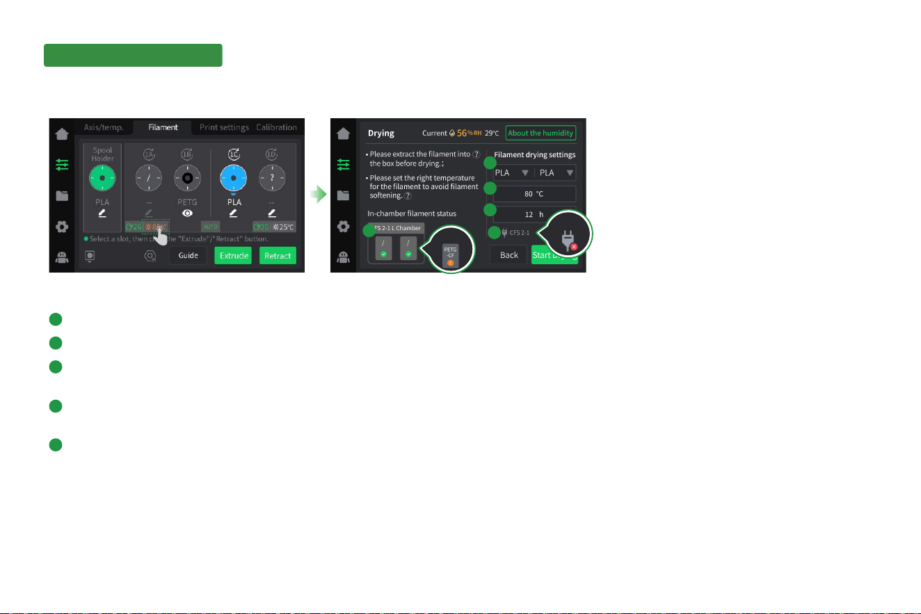
CFS 2 temperature and humidity status. Tap it to open the lament ding settings page.
f
a
b
c
d
e
Not
powered
Not
retracted
12
3.
Ding settings:
The lament in the current chamber is stored and meets the conditions for staing the ding process.
a
Before enabling the ding function, make sure the AC power supply is connected and switched on.
b
The two lament types for the current chamber are set to PLA by default. Select the appropriate
lament types based on the actual laments used.
c
The system intelligently matches a preset ding temperature based on the lament in the current
chamber. The temperature can be adjusted manually.
d
The system intelligently matches a preset ding duration based on the lament in the current chamber.
The duration can be adjusted manually.
e
3. Instructions for use3. Instructions for use3. Instructions for use
13
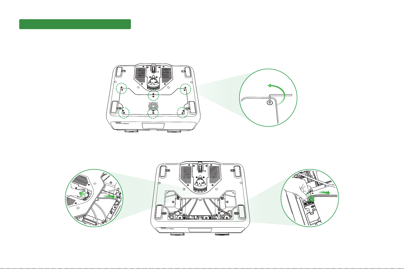
4.1 Replacing the internal PTFE tube
1.
Use an H2.0 hex key to remove the six screws and take o the cover.
2. Press both ends of the pneumatic ttings as shown below, then pull out the PTFE tube for replacement.
4. Tips and routine maintenance4. Tips and routine maintenance4. Tips and routine maintenance
14
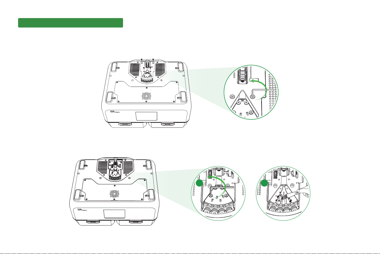
4.2 Cleaning debris from the 5-way tting
4. Tips and routine maintenance4. Tips and routine maintenance4. Tips and routine maintenance
1. Use an H2.0 hex key to remove the four screws securing the outer cover.
2. A: Use an H2.0 hex key to remove the four screws securing the transparent cover.
B: Use the included brush to clean the debris inside. Reinstall the pas in the reverse order of disassembly.
A B
Due to the dierences between dierent machine models, the actual objects and the images can dier. Please refer to the actual machine.
The nal explanation rights shall be reseed by Shenzhen Creality 3D Technology Co., Ltd.
18th Floor, JinXiuHongDu Building, Meilong Road, Xinniu Community,
Minzhi Street, Longhua District, Shenzhen City, China.
Ocial Website: www.creality.com
Tel: +86 755-8523 4565
E-mail: [email protected]