™
Warnings and considerations
WARNING! Turn OFF electrical power before installing or servicing this product.
Improper use or installation can cause SERIOUS INJURY, DEATH or LOSS/
DAMAGE OF PROPERTY.
ATTENTION! Coupez l’alimentation électrique avant d’installer ou de réparer
ce produit. Une mauvaise installation ou utilisation peut entraîner des blessures
graves, décès ou perte / dommages à la propriété.
WARNING! This device must be protected by a circuit breaker (20A max).
ATTENTION! Cet appareil doit être protégé par un disjoncteur (20A max.)
WARNING! Ground this device in accordance with the National Electric Code
(NEC) requirements. DO NOT rely solely upon the mounting plate’s contact with
a metal wall box for adequate grounding. Use the mounting plate’s ground wire
to make a secure connection to the safety ground of the electrical system.
ATTENTION! Mettez cet appareil à la terre conformément aux exigences du
National Electric Code (NEC). NE PAS compter uniquement sur le contact du
support de montage avec un boîtier arrière métallique pour une mise à la
terre adéquate. Utilisez le fil de terre du support de montage pour établir une
connexion sécurisée à la terre de sécurité du système électrique.
IMPORTANT! This device must be installed by a licensed electrician in
accordance with all national and local electrical codes.
IMPORTANT! If you are unsure about any part of these instructions, consult a
qualified electrician.
IMPORTANT! Use this device only with copper or copper-clad wire. Do not use
aluminum wiring. This product has not been approved for use with aluminum
wiring.
IMPORTANT! Using this product in a manner other than outlined in this
document voids your warranty. Further, Snap One is NOT liable for any damage
incurred with the misuse of this product. See “Troubleshooting.”
IMPORTANT! Do NOT use a power screwdriver to install this device. If you do,
you may overtighten the screws and strip them. Also, overtightening the screws
may interfere with proper button operation.
IMPORTANT! This is an electronic device with intricate components. Handle and
install with care!
IMPORTANT! When used in conjunction with an Auxiliary Keypad (C4-L-KA), the
wire connecting the Auxiliary Keypad to the dimmer must not exceed 45 m (150
ft.) at 120V AC and 30 m (100 ft.) at 240V AC.
IMPORTANT! *When dimming magnetic (MLV) loads, each transformer must be
loaded to at least 50% of its maximum load.
Installation instructions
1 Ensure that the location and intended use meet the following criteria:
• Do not exceed the load capacity requirements of the dimmer. Refer to the load
ratings in the specifications above for details.
• The range and performance of the Zigbee wireless control system is highly
dependent on the following: (1) distance between devices; (2) layout of the
home; (3) walls separating devices; and (4) electrical equipment located near
devices. To learn more about Zigbee Best Practices, see ctrl4.co/zigbee-bp.
• Do not install the device in a location near equipment that produces heat or cold
(e.g. air conditioning, furnace vents, fans, ovens, heaters, etc.) as this may cause
false triggers.
2 Turn o the local electrical power by either switching o the circuit breaker or
removing the fuse from the fuse box. To ensure the wires do NOT have power
running to them, use an inductive voltage detector.
3 Prepare each wire. Wire insulation should be
stripped back ½" (12.7 mm) from the wire end.
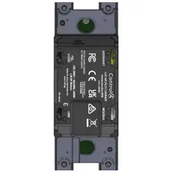
NOTE: You can use the strip gauge on the
back of the dimmer to check the proper
length.
Supported model
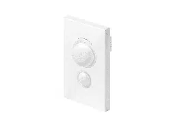
• C4-L-MDIM Control4 Lux Motion Dimmer
Introduction
The Control4® Lux Motion Dimmer operates independently or as part of a Control4 home
automation system. It installs in a standard wall box using typical wiring standards and
communicates to the Control4 system using a wireless connection.
Box contents
• Control4 Lux Motion Dimmer
• Warranty card
• Temporary rocker
• Control4 Lux Motion Dimmer Installation Guide (this document)
Mounting Plate required
The Control4 Lux Motion Dimmer requires a faceplate and mounting plate designed to fit
your install (1 gang, 2 gang, etc.) and are required before you install the dimmer.
Part numbers for faceplates and mounting plates:
• Lux Faceplate and Mounting Plate, 1 gang (C4-L-FP1-XX), 2 gang (C4-L-FP2-XX),
3 gang (C4-L-FP3-XX), 4 gang (C4-L-FP4-XX)
Specifications and supported load types
Model number C4-L-MDIM
Power requirements 120-240V AC ±10%, 50/60 Hz
Neutral required? No
Power consumption 120V: 1.32W all LEDs o, 1.51W all LEDs on
240V: 3.62W all LEDs o, 3.86W all LEDs on
Load types and ratings
Supported load types Dimming: Incandescent, halogen, electronic (solid state)
low voltage (ELV) transformers, magnetic (iron core,
inductive) low voltage (MLV) transformers*, LEDs
Switch mode: above load types and also motors
Load range Incand. LED ELV MLV Motor
120V / 240V 1-600W 1-600W 1-500W 1-500W 1/8 HP
Motion detection
Flat sensor lens 120°, 10 ft range
Curved sensor lens 150°, 25 ft range
Environmental
Operational temperature 0 to 40 ˚C (32 to 104 ˚F)
Humidity 5% to 95% non-condensing
Storage -20 to 70 ˚C (-4 to 158 ˚F)
Miscellaneous
Title 24 Occupancy Sensor
Compliance
Yes
Control communications Zigbee, IEEE 802.15.4, 2.4 GHz, 15-channel spread
spectrum radio
Lighting scenes per device 127 maximum
Actions per device 15 maximum per lighting scene
Wallbox volume 5.75 in
3
(94.2 cc)
Weight 0.05 kg (0.12 lb)
Shipping weight 0.08 kg (0.18 lb)
Compatible color kits C4-L-CKMD-XX
4 Identify your wiring application, and then see the appropriate wiring diagram in the
“Sample Wiring Configurations” section below.
5 Using a manual screwdriver, install the mounting plate to the wall box. Do not
overtighten the screws. Pull the wires through the mounting plate.
6 Connect the supplied ground wire lead to the ground wire in the wall box. Then,
using the supplied hardware, fasten the ground wire lead to whichever side of the
mounting plate that leaves the most space for the lighting device.
IMPORTANT! As described in the section Warnings and Considerations, DO NOT
rely solely upon the mounting plate’s contact with a metal wall box for adequate
grounding.
7 Identify and connect the wires to the back of the dimmer. Insert the wire into the
terminal and secure it by hand-tightening the terminal screw to 15 in-lb (1.7 Nm) of
torque.
NOTE: You must use the same size and type of wire in each terminal for proper
connection.
NOTE: The faceplate and mounting plate package includes labels for
international wiring standards. Make sure to label the wires to meet local
electrical codes.
IMPORTANT! The AUXILIARY connection is not used for a traditional traveler.
It cannot directly power a lighting load. It must be used only to connect to a
Black (Line In/Hot)
White (Neutral)
From Breaker
Black (Load)
White (Neutral)
To Load
Copper
(To ground)
Green
(To ground)
To Load
From Breaker
Black/Brown (Load)
White/Blue (Neutral)
Black/Brown
(Line in/Hot)
AUXILIARY LOAD
NEUTRAL LINE
Control4 Auxiliary Keypad. See “Sample Wiring Configurations.”
TIP: When installing this device in a multi-gang scenario, the Lux multi-gang
faceplate kits come with jumpers to easily connect multiple devices.
8 Fit the wires back into the wall box. Bend the wires in a zigzag pattern so that they
easily fold into the wall box.
Caution: Install buttons after device is installed in the wall box. Pushing the
device into the wall box with buttons installed may damage the device.
9 Insert the device into the mounting plate
and fasten it with screws. Overtightening
can warp the device, causing mechanical
malfunction and diculty mounting the
buttons and faceplate.
10 Install the temporary rocker onto
the device. The back of the rocker
has an arrow to indicate which end
goes up. Line up the rocker's tabs to
the device's pegs. Hold one side of
the rocker in place over the device
and snap the other side into place.
TIP: This device ships with a
temporary rocker on the device for basic operation until a finished, engraved
rocker can be ordered. Blank, unengraved rockers are also available. To replace
the temporary rocker with the engraved rocker, see the Control4 Lux Button
Installation Guide
(ctrl4.co/lux-butn-ig)
11 Install the sensor lens below the rocker. The lens snaps on
much like the rocker.
Caution: Do not touch the lens! This may render the
device inoperable or degrade performance.
Two lenses (flat and curved) are supplied in each color kit (C4-L-CKMD-XX).
The flat lens provides a sensing range of 10 ft and the curved lens provides a
sensing range of 25 ft.
12 Install the Control4 Faceplate following the instructions in the Control4
Lux Faceplate Installation Guide (ctrl4.co/lux-faceplate-ig).
13 Turn on power at the circuit breaker or replace the fuse from the fuse box.
White/Blue (Neutral)
Black/Brown (Line in/Hot)
To Load
To Load
From Breaker
From Breaker
AUXILIARY LOAD
NEUTRAL LINE
AUXILIARY LOAD
NEUTRAL LINE
AUXILIARY LOAD
NEUTRAL LINE
Black/Brown (Load)
To Load
Black/Brown
(Load)
Black/Brown
(Load)
To Load
Lux Motion Dimmer
Installation Guide
For the latest version of this guide and to view additional materials, open the URL below or scan the QR
code. Your device must be able to view PDFs.
CONTROL4 LUX QUICK START
ctrl4.co/lux-qs
CONTROL4 LUX WIRING GUIDE
ctrl4.co/lux-wiring
LATEST VERSION OF THIS GUIDE
ctrl4.co/lux-mdim-ig
™
Operation and configuration
On initial power up, all status LEDs on the dimmer illuminate green indicating that the
device has power. To set up this dimmer for use with a Control4 system, refer to the
Composer Pro User Guide.
To operate this dimmer as a stand-alone device if it is not programmed into a Control4
system:
• Click the top button to turn the light on.
• Click the bottom button to turn the light o.
Use air gap switch when changing the bulb or fixture
With the dimmer turned o, some current still flows through the load. An Air Gap switch
is located at the top of the dimmer and disconnects power to the load.
Perform the following steps to change a bulb or fixture:
1 Turn o the load and remove the faceplate from the dimmer.
2 Slide the Air Gap switch upward to engage the air gap.
3 Change the bulb or service the fixture.
4 Slide the Air Gap switch downward and replace the faceplate.
Button tap sequences
The button tap sequences are defined in the table below. Button tap sequences that
require a single button use the top button. For example, the factory reset sequence is 9
taps on the top, then, 4 on the bottom, and then, 9 on the top.
Function Button Sequence
Identify 4
Zigbee channel 7-4-7
Reboot 15
Factory reset 9-4-9
Leave mesh and reset 13-4-13
Troubleshooting
If the light does not turn on:
• Ensure at least one LED on the face of the dimmer is lit.
• Ensure the light bulb is not burned out and is screwed in tightly.
• Ensure that the circuit breaker is not turned OFF or tripped.
• Check for proper wiring (see “Sample Wiring Configurations”).
LED status information
Fault status Zigbee status
× 1 Mosfet fault Not identified
× 2 Short circuit fault Identifying
× 3 Over current fault Found Zigbee mesh
× 4 Line voltage fault Did not find Zigbee mesh
× 5 Zero cross fault Joined Zigbee mesh
× 6 Temperature fault
× 8 Bootup power/wiring fault
× 1 Incorrect product fault
× 3 Self-test fault
× 1 Airgap actuated
× 2 Manufacturing ID fault
Care and cleaning
• Do NOT paint the dimmer or its faceplate.
• Do NOT use any chemical cleaners to clean the dimmer.
• Clean surface of the dimmer with a soft damp cloth as needed.
—Flashing LED —Solid LED
Multiple device location using Auxiliary Keypad
If you have a traveler wire to another wall box, you can install an auxiliary keypad to control the motion dimmer.
IMPORTANT! When used in conjunction with an Auxiliary Keypad (C4-L-KA), the wire connecting the Auxiliary Keypad to the dimmer must not exceed 45 m (150 ft.)
at 120V AC, and 30 m (100 ft.) at 240V AC.
Motion Detection Map
The flat lens provides a 10 ft sensing range and the curved lens provides a 25 ft sensing range.
To Load
From Breaker
To Keypad Dimmer Switch
To Auxiliary
Keypad
NEUTRAL AUXILIARY
AUXILIARY LOAD
NEUTRAL LINE
Black/Red/Brown
(Auxiliary)
White/Blue
(Neutral)
Black/Brown (Load)
Black/Red/Brown
(Auxiliary)
Black/Brown
(Line in/Hot)
White/Blue (Neutral)
Curved lens
25 ft range
150° arc
Flat lens
10 ft range
120° arc
Copyright ©2025, Snap One, LLC. All rights reserved. Snap One and its respective logos are registered trademarks or trademarks of Wirepath Home Systems, LLC, dba “Control4” and/or dba “SnapAV” in the
United States and/or other countries. 4Store, 4Sight, Control4 My Home, Snap AV, Araknis Networks, BakPak, Binary, Dragonfly, Episode, Luma, Mockupancy, Nearus, NEEO, Optiview, OvrC, Pakedge, Sense,
Strong, Strong Evolve, Strong Versabox, SunBriteDS, SunBriteTV, Triad, Truvision, Visualint, WattBox, Wirepath, and Wirepath ONE are also registered trademarks or trademarks of Wirepath Home Systems, LLC.
Other names and brands may be claimed as the property of their respective owners. All specifications subject to change without notice.
200-00751-A.4 2026-01-09 MK
Warranty and legal information
Find details of the product’s Limited Warranty at snapone.com/legal or request a paper
copy from Customer Service at 866.424.4489.
Find other legal resources, such as regulatory notices and patent information, at
snapone.com/legal.
Sample wiring configurations
Single device location
To Load
From Breaker
Black/Brown (Load)
White/Blue (Neutral)
Black/Brown
(Line in/Hot)
AUXILIARY LOAD
NEUTRAL LINE
Single device, no-neutral configuration
To Load
AUXILIARY LOAD
NEUTRAL LINE
White/Blue (Load)
Black/Brown
(Line in/Hot)
CONTROL4 LUX QUICK START
ctrl4.co/lux-qs
CONTROL4 LUX WIRING GUIDE
ctrl4.co/lux-wiring
More information and help
For the latest version of this guide and to view additional materials, open the URL below
or scan the QR code. Your device must be able to view PDFs.
LATEST VERSION OF THIS GUIDE
ctrl4.co/lux-mdim-ig

1355 W. Innovation Way, Suite 125 • Lehi, UT 84043
adiglobal.com
Regulatory Compliance & Safety Information for Model C4-L-UDIM, C4-L-KDS, C4-L-MDIM,
C4-L-NNDSW
Electrical Safety Advisory
Sécurité électrique consultatif
Important Safety Instructions
Consignes de sécurité importantes
Read the safety instructions before using this product.
Lisez les consignes de sécurité avant d'utiliser ce produit.
1. Read these instructions.
Lisez ces instructions.
2. Keep these instructions.
Conservez ces instructions.
3. Heed all warnings.
Respectez tous les avertissements.
4. Follow all instructions.
Suivez toutes les instructions.
5. Do not use this apparatus near water.
Ne pas utiliser cet appareil près de l'eau.
6. Clean only with dry cloth.
Nettoyez-le uniquement avec un chiffon sec.
7. Do not block any ventilation openings. Install in accordance with the manufacturer’s
instructions.
Ne pas bloquer les ouvertures de ventilation. Installer conformément aux instructions du
fabricant.
8. Do not install near any heat sources such as radiators, heat registers, stoves, or other
apparatus (including amplifiers) that produce heat.
Ne pas installer près de sources de chaleur telles que des radiateurs, registres de
chaleur, poêles, ou autres appareils (incluant les amplificateurs) qui produisent de la
chaleur.
9. Only use attachments/accessories specified by the manufacturer.
Utilisez uniquement des fixations / accessoires spécifiés par le fabricant.
10. Use only with the cart, stand, tripod, bracket, or table specified by the manufacturer, or
sold with the apparatus. When a cart is used, use caution when moving the
cart/apparatus combination to avoid injury from tip-over.
Utilisez uniquement avec le chariot, le socle, le trépied, le support ou la table spécifiés
par le fabricant ou vendu avec l'appareil. Lorsque vous utilisez un chariot, soyez prudent

1355 W. Innovation Way, Suite 125 • Lehi, UT 84043
adiglobal.com
lorsque vous déplacez l'ensemble chariot / appareil pour éviter des blessures dues au
renversement.
11. Refer all servicing to qualified service personnel. Servicing is required when the
apparatus has been damaged in any way, such as power-supply cord or plug is
damaged, liquid has been spilled or objects have fallen into the apparatus, the apparatus
has been exposed to rain or moisture, does not operate normally, or has been dropped.
Confiez toutes les réparations à un personnel qualifié. Une réparation est nécessaire
lorsque l'appareil a été endommagé de quelque façon que ce soit le cordon
d'alimentation ou la fiche est endommagé, du liquide a été renversé ou si des objets sont
tombés dans l'appareil, l'appareil a été exposé à la pluie ou à l'humidité, ne fonctionne
pas normalement, ou s'il est tombé.
12. Protect the power cord from being walked on or pinched particularly at plugs,
convenience receptacles, and the point where they exit from the apparatus.
Protégez le cordon d'alimentation ne soit piétiné ou pincé, en particulier au niveau des
fiches, des prises et au point où il sort de l'appareil.
13. This equipment uses AC power which can be subjected to electrical surges, typically
lightning transients which are very destructive to customer terminal equipment connected
to AC power sources. The warranty for this equipment does not cover damage caused
by electrical surge or lightning transients. To reduce the risk of this equipment becoming
damaged it is suggested that the customer consider installing a surge arrestor. Unplug
this apparatus during lightning storms or when unused for long periods of time.
Cet équipement utilise la puissance AC qui peuvent être soumis à des surtensions
électriques, la foudre généralement transitoires qui sont très destructives envers les
équipements terminaux connectés à des sources d'alimentation CA. La garantie de cet
appareil ne couvre pas les dommages causés par les surtensions électriques ou
transitoires de foudre. Pour réduire le risque de cet équipement devient endommagé, il
est suggéré que le client envisager l'installation d'un limiteur de surtension. Débranchez
cet appareil pendant les orages ou lorsqu'il n'est pas utilisé pendant de longues périodes
de temps.
14. To completely disconnect unit power from the AC mains, remove the power cord from the
appliance coupler and/or turn off the circuit breaker. To reconnect power, turn on the
circuit breaker following all safety instructions and guidelines. The circuit breaker shall
remain readily accessible.
Pour débrancher complètement l'alimentation secteur du réseau secteur, retirez le
cordon d'alimentation du coupleur de l'appareil et / ou éteignez le disjoncteur. Pour
reconnecter l'alimentation, allumez le disjoncteur en suivant toutes les consignes et
consignes de sécurité. Le disjoncteur doit être facilement accessible.
15. This product relies on the buildings installation for short-circuit (overcurrent) protection.
Ensure that the protective device is rated not greater than: 20A.
Ce produit repose sur l'installation des bâtiments pour les courts-circuits (surintensité) de
protection. Assurez-vous que le dispositif de protection est assignée ne dépassant pas:
20A.

1355 W. Innovation Way, Suite 125 • Lehi, UT 84043
adiglobal.com
16. WARNING – Power Sources, Grounding, Polarization
This product requires a properly grounded outlet for safety. This plug is designed to be
inserted into a NEMA 5-15 (three-prong grounded) outlet only. Do not force the plug into
an outlet that is not designed to accept it. Never dismantle the plug or alter the power
cord, and do not attempt to defeat the grounding feature by using a 3-to-2 prong adapter.
If you have a question about grounding, consult your local power company or qualified
electrician.
If a rooftop device such as a satellite dish connect to the product, ensure that the devices’
wires are also properly grounded.
The bonding point can be used to provide a common ground to other equipment. This
bonding point can accommodate minimum 12 AWG wire and should be connected using
the required hardware specified by the other bonding point. Please use termination for
your equipment in accordance with the applicable local agency requirements.
AVERTISSEMENT - Sources d'alimentation, mise à la terre, polarisation
Ce produit nécessite une prise correctement mise à la terre pour des raisons de sécurité.
Cette fiche est conçue pour être insérée dans une prise NEMA 5-15 (trois broches mise à
la terre) uniquement. Ne forcez pas la fiche dans une prise qui n'est pas conçue pour
l'accepter. Ne démontez jamais la fiche ou ne modifiez pas le cordon d'alimentation, et
n'essayez pas de désactiver la fonction de mise à la terre en utilisant un adaptateur 3 à 2
broches. Si vous avez une question sur la mise à la terre, consultez votre compagnie
d'électricité locale ou un électricien qualifié.
Si un appareil sur le toit tel qu'une antenne parabolique se connecte au produit, assurez-
vous que les fils des appareils sont également correctement mis à la terre.
Le point de liaison peut être utilisé pour fournir une masse commune à d'autres
équipements. Ce point de connexion peut accueillir un fil de 12 AWG minimum et doit
être connecté à l'aide du matériel requis spécifié par l'autre point de connexion. Veuillez
utiliser une terminaison pour votre équipement conformément aux exigences des
agences locales applicables.
17. Notice – For indoor use only, Internal components are not sealed from the environment.
The device can only be used in a fixed location such as a telecommunication center, or a
dedicated computer room. When you install the device, ensure that the protective
earthing connection of the socket-outlet is verified by a skilled person. Suitable for
installation in information technology rooms in accordance with Article 645 of the National
Electrical Code and NFP 75.
Avis – Pour une utilisation en intérieur uniquement, les composants internes ne sont pas
scellés de l'environnement. L'appareil ne peut être utilisé que dans un lieu fixe tel qu'un
centre de télécommunication, ou une salle informatique dédiée. Lors de l'installation de
l'appareil, assurez-vous que la mise à la terre de protection de la prise de courant est
vérifiée par une personne qualifiée. Convient pour une installation dans des salles
informatiques conformément à l'article 645 du Code national de l'électricité et NFP 75.
18. This product can interfere with electrical equipment such as tape recorders, TV sets,
radios, computers, and microwave ovens if placed in close proximity.
Ce produit peut interférer avec des appareils électriques tels que les magnétophones,
téléviseurs, radios, ordinateurs et fours à micro-ondes si placés à proximité.
19. Never push objects of any kind into this product through cabinet slots as they may touch
dangerous voltage points or short out parts that could result in fire or electric shock.
1355 W. Innovation Way, Suite 125 • Lehi, UT 84043
adiglobal.com
N'introduisez jamais d'objets d'aucune sorte dans ce produit à travers les fentes du boîtier car ils
pourraient toucher des points de tension dangereux ou court-circuiter des pièces qui pourraient
entraîner un incendie ou un choc électrique.
20. WARNING – No user serviceable parts inside. If the product is not operating properly, do
not remove any part of the unit (cover, etc.) for repair. Unplug the unit and consult the
warranty section of the owner’s manual.
AVERTISSEMENT – Aucune pièce réparable par l'utilisateur à l'intérieur. Si le produit ne
fonctionne pas correctement, ne retirez aucune pièce de l'appareil (couvercle, etc.) pour
réparation. Débranchez l'appareil et consultez la section de garantie du manuel du propriétaire.
The lightning flash and arrow head within the triangle is a warning sign alerting
you of dangerous voltage inside the product
L'éclair et la flèche dans le triangle est un signe d'alerte pour vous avertir
d'une tension dangereuse à l'intérieur du produit
Caution: To reduce the risk of electric shock, do not remove cover (or back).
No user serviceable parts inside. Refer servicing to qualified service
personnel.
Attention: Pour réduire le risque de choc électrique, ne pas retirer le couvercle
(ou l'arrière). Aucune pièce réparable par l'utilisateur. Confiez l'entretien à un
personnel qualifié.
The exclamation point within the triangle is a warning sign alerting you of
important instructions accompanying the product.
Le point d'exclamation dans un triangle est un signe d'avertissement vous
signale des instructions importantes accompagnant le produit.
See marking on bottom / back of product
Voir le marquage sur les bas / dos du produit
Warning!: To reduce the risk of electrical shock, do not expose this
apparatus to rain or moisture
AVERTISSEMENT! Pour réduire le risque de choc électrique,
n'exposez pas cet appareil à la pluie ou à l'humidité.
Save these instructions
Conservez ces instructions
Compliance of this equipment is confirmed by the following label that is placed on the equipment:
Conformité de cet appareil est confirmé par le symbole suivant qui est placé sur l'équipement:

1355 W. Innovation Way, Suite 125 • Lehi, UT 84043
adiglobal.com
USA & Canada Compliance
FCC Part 15, Subpart B & IC Unintentional Emissions Interference Statement
This equipment has been tested and found to comply with the limits for a Class B digital device,
pursuant to Part 15 of the FCC rules. These limits are designed to provide reasonable protection
against harmful interference when the equipment is operated in a residential installation. This
equipment generates uses and can radiate radio frequency energy and, if not installed and used
in accordance with the instructions, may cause harmful interference to radio communications.
However, there is no guarantee that interference will not occur in a particular installation. If this
equipment does cause harmful interference to radio or television reception, which can be
determined by turning the equipment off and on, the user is encouraged to try to correct the
interference by one or more of the following measures:
Reorient or relocate the receiving antenna.
Increase the separation between the equipment and receiver.
Connect the equipment into an outlet on a circuit different from that to which the receiver
is connected.
Consult the dealer or an experienced radio/TV technician for help.
This device complies with part 15 of the FCC rules. Operation is subject to the following two
conditions: (1) This device may not cause harmful interference, and (2) this device must accept
any interference received, including interference that may cause undesired operation.
Cet appareil est conforme à la section 15 des règles. Son utilisation est soumise aux deux
conditions suivantes: (1) Cet appareil ne doit pas causer d’interférences nuisibles et (2) cet
appareil doit accepter toutes les interférences reçues, y compris celles pouvant entraîner un
fonctionnement non souhaité.
IMPORTANT! Any changes or modifications not expressly approved by the party responsible for
compliance could void the user’s authority to operate this equipment.
IMPORTANT! Tous les changements ou modifications pas expressément approuvés par la partie
responsable de la conformité ont pu vider l’autorité de l’utilisateur pour actionner cet équipement.
Canada Warning Statement:
CAN ICES-3 (B)/NMB-3(B)
• This product meets the applicable Innovation, Science and Economic Development Canada
technical specifications.
• Ce produit répond aux spécifications techniques applicables à l'innovation, Science et
Développement économique Canada.
FCC Part 15, Subpart C / RSS-247 Intentional Emissions Interference Statement
Compliance of this equipment is confirmed by the following certification numbers that are placed
on the equipment:
Notice: The term “FCC ID:” and “IC:” before the certification number signifies that FCC and
Industry Canada technical specifications were met.
FCC ID: 2AJAC-C4LUX1
IC: 7848A-C4-LUX1
FCC ID: 2AJAC-C4LUX2
IC: 7848A-C4-LUX2
1355 W. Innovation Way, Suite 125 • Lehi, UT 84043
adiglobal.com
This equipment must be installed by qualified professionals or contractors in accordance with
FCC Part 15.203 & IC RSS-247, Antenna Requirements. Do not use any antenna other than the
one provided with the unit.
FCC Partie 15, sous-partie C / RSS-247 Déclaration volontaire des émissions interférences
Conformité de cet appareil est confirmé par les chiffres de certification suivants qui sont placés
sur l'équipement:
Avis: Le terme «FCC ID:" et "IC:" devant le numéro de certification signifie que les spécifications
techniques de la FCC et d'Industrie Canada ont été respectées.
FCC ID: 2AJAC-C4LUX1
IC: 7848A-C4LUX1
FCC ID: 2AJAC-C4LUX2
IC: 7848A-C4-LUX2
Cet équipement doit être installé par des professionnels qualifiés ou entrepreneurs conformément
aux normes FCC partie 15.203 & IC RSS-247, Exigences d'antenne. Ne pas utiliser une antenne
autre que celui fourni avec l'appareil.
Cet émetteur ne doit pas être localisé ou fonctionner avec d'autres antennes ou transmetteurs.
Les opérations dans la bande 5.15-5.25GHz sont limitées à l'utilisation à l'intérieur seulement.
RF Radiation Exposure Statement
This equipment complies with FCC RF and IC radiation exposure limits set forth for an
uncontrolled environment. This equipment should be installed and operated with a minimum
distance of 20 centimeters between the radiator and your body or nearby persons.
Déclaration d'exposition aux radiations RF
Cet équipement est conforme aux limites d'exposition aux rayonnements RF et IC de la FCC
définies pour un environnement non contrôlé. Cet équipement doit être installé et utilisé avec une
distance minimale de 20 centimètres entre le radiateur et votre corps ou des personnes proches.
Europe Compliance
Compliance of this equipment is confirmed by the following logo that is placed on the product ID
label that is placed on the bottom of the equipment. The full text of the EU Declaration of
Conformity (DoC) is available on the regulatory webpage:
This product can be put into service in all of the EU member states, European Free Trade Association
(EFTA) and EU candidate countries without any restriction.
1355 W. Innovation Way, Suite 125 • Lehi, UT 84043
adiglobal.com
BE
BG
CZ
DK
DE
EE
IE
EL
ES
FR
HR
IT
CY
LV
LT
LU
HU
MT
NL
AT
PL
PT
RO
SI
SK
FI
SE
UK
IS
LI
NO
CH
MK
AL
RS
TR
The frequency and maximum transmitted power in EU are listed as below:
2412 - 2472 MHz: 18 dBm
United Kingdom (UK) Compliance
Compliance of this equipment is confirmed by the following logo that is placed on the product ID
label that is placed on the bottom of the equipment. The full text of the UK Declaration of
Conformity (DoC) is available on the regulatory webpage:
Recycling
Snap One understands that a commitment to the environment is essential for a health life and
sustainable growth for future generations. We are committed to supporting the environmental
standards, laws, and directives that have been put in place by various communities and countries
that deal with concerns for the environment. This commitment is represented by combining
technological innovation with sound environmental business decisions.
WEEE Compliance
Snap One is committed to meeting all requirements of the Waste Electrical and Electronic
Equipment (WEEE) directive (2012/19/EC). The WEEE directive requires the manufacturers of
electrical and electronic equipment who sell in EU countries: (1) label their equipment to notify
customers that it needs to be recycled, and (2) provide a way for their products to be
appropriately disposed of or recycled at the end of their product lifespan. For collection or
recycling of Snap One products, please contact your local Snap One representative or dealer.

1355 W. Innovation Way, Suite 125 • Lehi, UT 84043
adiglobal.com
Australia & New Zealand Compliance
Compliance of this equipment is confirmed by the following logo that is placed on the product ID
label that is placed on the bottom of the equipment.
About this Document
Copyright © 2026 Snap One All rights reserved.