
Optimow 4 / 5 / 7 / S / M
Original instructions/Übersetzung der ursprünglichen Anweisungen/Traducción de las instrucciones originales/Tradu-
zione delle istruzioni originali/Traduction des instructions d’origine/Tradução das instruções originais/Vertaling van de
originele gebruiksaanwijzing/Перевод оригинальных инструкций/Alkuperäisten käyttöohjeiden käännös/Översättning
av originalanvisningarna/Oversettelse av den originale bruksanvisningen/Oversættelse af den originale instruktions-
bog/Tłumaczenie oryginalnej instrukcji/Překlad originálního návodu/Preklad originálneho návodu/Prevod izvirnih navo-
dil/Prijevod izvornih uputa/Az eredeti utasítás fordítása/Traducere a instrucţiunilor originale/Превод на оригиналните
инструкции/Originalių instrukcijų vertimas/Sākotnējā norādījuma tulkojums/Algse juhendi tõlge
Robotic Lawnmower
Rasenmähroboter
Cortacésped robótico
Tondeuse à gazon robotique
Gogo Tosaerba
Corta-relva robótico
Robotmaaier
Роботизированная газонокосилка
Robottiruohonleikkuri
Robotgräsklippare
Robotklipper
Robotplæneklipper
Robokosiarka
Robotická sekačka na trávu
Robotická kosačka
Robotska kosilnica
Robotska kosilica
Robotfűnyíró
Robot de tuns iarba
Роботизирана ливадна косачка
OPERATOR’S MANUAL
BEDIENUNGSHANDBUCH
MANUAL DEL OPERARIO
MANUALE DI ISTRUZIONI
MANUEL OPÉRATEUR
MANUAL DO OPERADOR
GEBRUIKERSHANDLEIDING
РУКОВОДСТВО ОПЕРАТОРА
KÄYTTÖOPAS
ANVÄNDARHANDBOK
BRUKERHÅNDBOK
BRUGERVEJLEDNING
INSTRUKCJA OBSŁUGI
NÁVOD K OBSLUZE
NÁVOD NA OBSLUHU
PRIROČNIK ZA UPRAVLJAVCA
PRIRUČNIK ZA RUKOVATELJE
KEZELŐI KÉZIKÖNYV
MANUAL DE INSTRUCŢIUNI
РЪКОВОДСТВО НА ОПЕРАТОРА
Robotas vejapjovė
OPERATORIAUS VADOVAS
Robotizēts zāles pļāvējs
LIETOTĀJA ROKASGRĀMATA
Robotmuruniiduk
KASUTUSJUHEND
BG
CS
DA
DE
ES
FI
FR
HU
IT
NL
NO
PL
PT
RO
RU
SK
SL
SV
EN
HR
LT
LV
ET

GREENWORKSTOOLS.EU
2
EN
Version 4 - 2023.09.22
The materials, technical data, and gures in this manual are provided for guidance only and are not
binding. The manufacturer reserves the right to make any changes to the technical characteristics
and all features of operation, materials, technical data, or gures without prior warning.
The following pages contain important safety and
operating instructions
Carefully read and review all safety instructions,
warnings and cautions contained in this manual.
Failure to read and follow these instructions,
warnings and cautionary statements may result
in severe injury or death to persons and pets or
damage to personal property.

GREENWORKSTOOLS.EU
3
EN
Contents
Product Safety .........................................................................................................................4
Reading the operator manual ................................................................................... 4
Operational safety ......................................................................................................... 6
Product Unboxing ..................................................................................................................7
Introduction ............................................................................................................................. 8
Installation ................................................................................................................................ 8
Planning Layout and Preparation ............................................................................ 8
Installing and Connecting the Charging Station................................................9
Position for the charging station as follows: ........................................................ 9
Connecting the Power Supply ................................................................................10
Initial Charging of the Battery .................................................................................11
Installing the Boundary Wire ...................................................................................12
Installing a Guide Wire ...............................................................................................15
Calibrating and Initial Start Up ...............................................................................17
Operation ................................................................................................................................18
Starting and Stopping the Mower .........................................................................18
Switching O the Mower ..........................................................................................18
Adjusting Cutting Height ..........................................................................................18
Lifting and Carrying the Mower .............................................................................19
Pairing Mobile App to Mower .................................................................................19
Maintenance ..........................................................................................................................20
Removing the Body from Chassis ..........................................................................20
Cleaning ..........................................................................................................................20
Replacing Blades ..........................................................................................................21
Maintaining the Battery ............................................................................................21
Winter Storage Mower ...............................................................................................22
Winter storage Charging Station............................................................................22
Troubleshooting ...................................................................................................................23
Indicator LEDs on Mower ..........................................................................................23
Symptoms ......................................................................................................................24
Breaks in Boundary Wire and Guide Wire ............................................................24
Technical Data .......................................................................................................................25
Environmental Protection .................................................................................................27
Warranty Terms .....................................................................................................................28
CE Declaration of Conformity ..........................................................................................29
Declaration of Conformity (UK) .......................................................................................30
Version 4 - 2023.09.22
GREENWORKSTOOLS.EU
4
EN
Version 4 - 2023.09.22
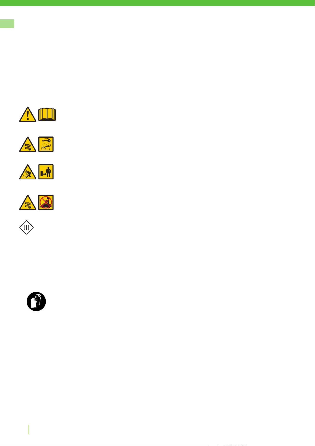
EXPLANATION OF SYMBOLS ON THE MOWER
This is a dangerous power tool. Use care when operating and follow all safety
instructions and warnings.
Read the operator manual carefully before operating the mower.
Remove the safety key before working on or lifting the mower.
Hazard of thrown objects during operation.
Keep a safe distance from the mower when operating and keep people, especially
children, pets and bystanders away from the area where mower is being operated.
Do not ride on the mower.
Class III appliance
As a complement to this operator manual, more information is available on the website:
www.greenworkstools.eu
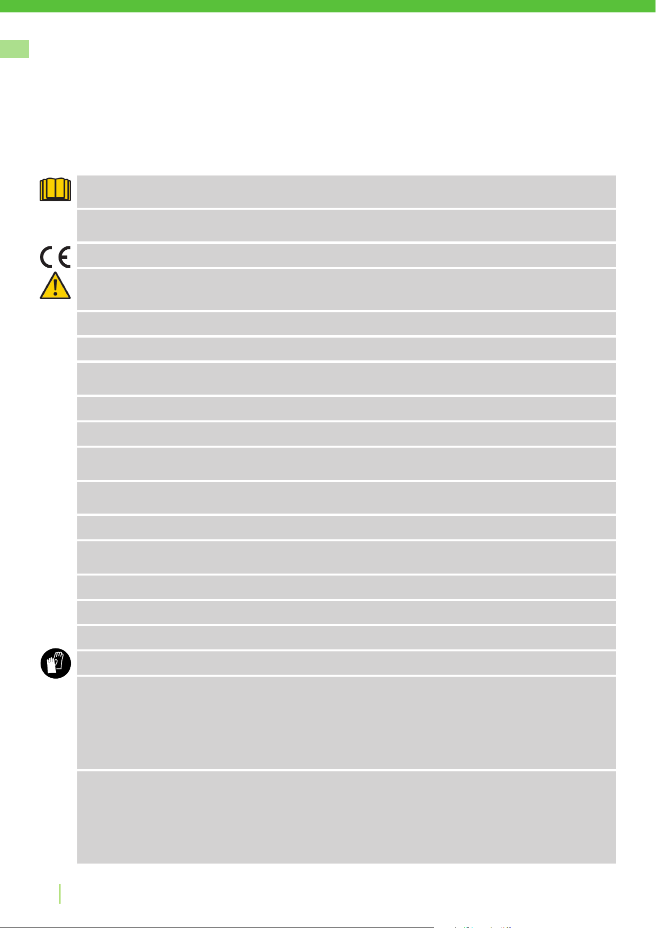
READING THE OPERATOR MANUAL
The following symbols are important for reading and understanding
the operating instructions.
Wear protective gloves
The following system is used in the operator manual to make it easier to understand:
• WARNING! Warning texts alert users and consumers to the existence and nature of hazards so
that they can prevent injury by appropriate conduct during use of the product.
• CAUTION: Caution texts alert users and consumers to the existence and nature of product risks so that
they can prevent damaging the product by appropriate conduct during use of the product.
• NOTE: Notes inform users and consumers about additional information about product use.
• Text written in bold italics refers to another section in the operator manual.
• Text written in bold refers to settings on the mower.
Product Safety

GREENWORKSTOOLS.EU
5
EN
Version 4 - 2023.09.22
Product Safety
IMPORTANT
READ CAREFULLY BEFORE USE! KEEP FOR FUTURE REFERENCE!
Training
WARNING! Automatic lawnmower! Keep away from the machine! Supervise children!
• Read the instructions carefully. Be familiar with the controls and the proper use of the machine.
• Never allow people unfamiliar with these instructions or children to use the machine. Local regulations
may restrict the age of the operator.
• The operator or user is responsible for accidents or hazards occurring to other people or their property.
Preparation
• Ensure the correct installation of boundary and guide wires as instructed.
• Periodically inspect the area where the machine is to be used and remove all stones, sticks, wires, bones,
and other foreign objects.
• Periodically visually inspect to see that the blades, blade bolts and cutter assembly are not worn or
damaged. Replace worn or damaged blades and bolts in sets to preserve balance.
General
• Never operate the machine with defective guards, or without safety devices, for example the body, in
place.
• Do not put hands or feet near or under rotating parts.
• Never pick up or carry an machine while the motor is running.
• Remove (or Operate) the disabling device from the machine
- before clearing a blockage;
- before checking, cleaning or working on the machine.
• Do not leave the machine to operate unattended if you know that there are pets, children or people in the
vicinity.
Maintenance and storage
• Keep all nuts, bolts, and screws tight to be sure the machine is in safe working condition.
• Replace worn or damaged parts for safety.
• Ensure that only replacement cutting means of the right type are used.
• Ensure that batteries are charged using the correct charger recommended by the manufacturer. Incorrect
use may result in electric shock, overheating or leakage of corrosive liquid from the battery.
• In the event of leakage of electrolyte ush with water/neutralizing agent, seek medical help if it comes
into contact with the eyes, etc.
• Servicing of the machine should be according to manufacturers’ instructions.
WARNING! This appliance contains batteries that are only replaceable by a skilled persons.
WARNING! For the purposes of recharging the battery, only use the detachable supply unit
provided with this appliance.
GREENWORKSTOOLS.EU
6
EN
Version 4 - 2023.09.22
OPERATIONAL SAFETY
This operator manual contains all of the basic information concerning the safe operation
and maintenance of the mower.
Product Safety
Carefully read all the safety precautions and instructions in this operator manual before operating the mower. Save this operator manual for
future reference. Follow manufacturer instructions regarding installation, operation, maintenance, and repair.
This mower is designed to mow grass in open and level areas. Use only equipment recommended by the manufacturer. All other types of use
are incorrect.
This mower conforms to CE safety standards and directives concerning electromagnetic compatibility, machines, and low voltage.
The mower is not intended for use by persons (including children) with reduced physical, sensory, or mental capabilities, or lack of experience
and knowledge, unless they have been given supervision or instruction concerning use of the appliance by a person responsible for their
safety.
Children should be supervised to ensure that they do not play with the appliance.
The mower must only be operated, maintained, and repaired by persons that fully understand its special characteristics and safety regulations.
Start the mower in accordance with the instructions. When the safety key is in the Enabled position, keep your hands and feet away from the
rotating blades.
Never put your hands and feet under the mower.
Do not modify the original design of the mower. All modications void the guarantee.
Switch o mower using the STOP button on the mower when persons, especially children, or pets are in the cutting area. It is recommended
that the mower be programmed for use during hours when the area is free from persons or pets.
Remove objects from the operating area such as branches, toys, stones, tools that can damage the blades. The mower can fasten on objects in
the operating area and help may be required to remove the object before the mower can continue mowing.
Never lift up the mower or carry it with the safety key inserted.
Always switch o the mower using the STOP button when the mower is not in use. The mower can only start when the safety key is inserted
and the START button is pressed.
Do not use the mower with a defective blade disc or body.
Do not let persons who do not know how the mower works and behaves use it.
Do not put anything on top of the mower or its charging station.
Always wear protective gloves when working with the mower’s blades.
In case there is risk of a lightning storm where the mower is installed, please take the following actions:
- Disconnect both boundary wires and guide wires from the charging station.
- Disconnect the charging station from the power socket.
- Place the mower indoors if possible.
When the risk of lightning is over reconnect all boundary and guide wires to the charging station. Connect power supply to the wall socket and
place the mower in the charging station.
When a mower is operating in a public area the operating area shall be surrounded with clearly visible warning signs. The warning signs shall
have the following text:
Warning!
Automatic lawnmower!
Keep away from the machine!
Supervise children!
GREENWORKSTOOLS.EU
7
EN
Version 4 - 2023.09.22
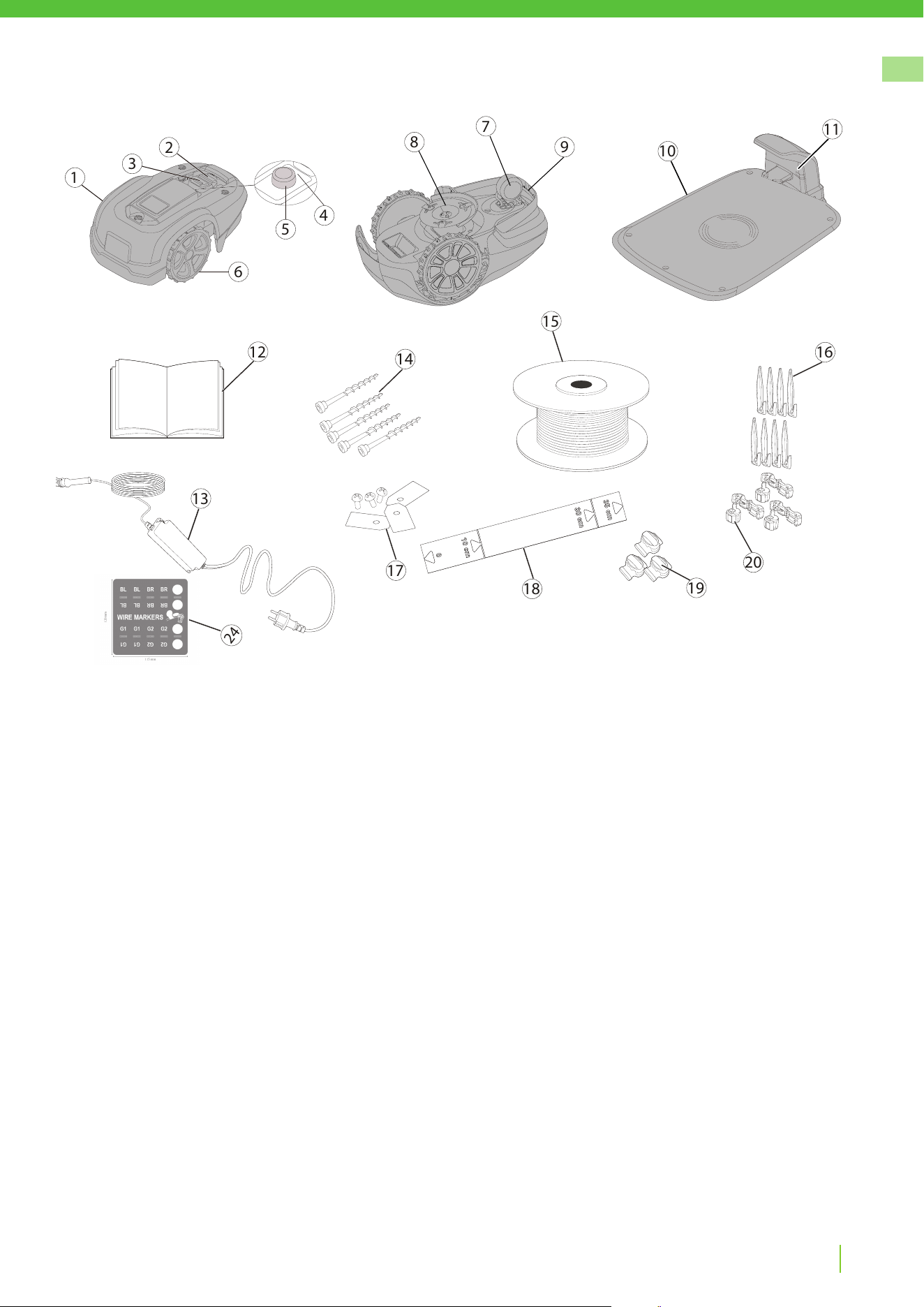
1 Removable cover
2 Stop button
3 Start button
4 LED indicators
5 Cutting height adjustment
6 Front wheels
7 Rear wheels
8 Blade disc
9 Carrying handle
10 Charging station
11 LED for operation check
12 Operator manual and quick guide
13 Power supply*
14 Screws for securing charging station (x5)
15 Loop wire for boundary and guide wire
16 Wire pegs
17 Extra blades and screws (x3)
18 Ruler (break o carton top)
19 Splice and guide wire connectors
20 Loop wire connectors
21 Wire marker label
* The appearance of the power supply may dier depending on market.
Unbox the mower and installation materials. Make certain that all parts shown in Figure 1 are included and
undamaged. Contact your retailer if any items are missing or damaged.
Keep the Quick Guide in a safe place since it contains the unique pairing code for your mower.
Product Unboxing
7
8
9
10
12
14
15
16
13
17
18
19
20
1
6
2
3
5
4
11
24

GREENWORKSTOOLS.EU
8
EN
Version 4 - 2023.09.22
Installation
Read the entire section before beginning installation. Installation aects mower capability.
Plan the installation carefully.
The following are the main tasks within the installation:
• Planning layout and preparation
• Installing and connecting the charging station
• Connecting the power supply
• Initial charging of the battery
• Installing the boundary wire
• Installing the guide wire
• Calibrating and initial start up
PLANNING LAYOUT AND PREPARATION
Ensure that the following conditions exist in the operating area where the mower will be used:
• The grass is shorter than 10 cm.
• There are no stones, loose pieces of wood, wire, live mains cables, and other foreign objects.
• The operating area is even and has no ditches, grooves, and steep slopes greater than 30%.
The following tools are required for installation, but not included:
• Hammer/rubber mallet to drive the pegs into the ground
• Combination pliers to cut the boundary wire
• Pliers wrench to press the couplers together
• Hex key, 6 mm for securing the charging station to ground
Introduction
How the robotic lawnmower works
The product is an autonomous appliance that can mow the grass evenly in a random pattern. The boundary
wire delimits the working area around the edge and isolate the xed objects. The product will drive back to the
charging station when the battery needs to be charged. It is equipped with various sensors to operate safely
and smartly.
After following the installation instructions in the manual and in the App, the robot will be ready to take care of
your lawn.
Connectivity
The product supports IoT (Internet of Thing) so it can be connected to appropriate App via Bluetooth. The
App provides operation settings for your own robot and makes it possible to control it remotely.
It also supports FOTA (Firmware over the air) via the App so it can be updated to the latest software to
get the best performance.
GREENWORKSTOOLS.EU
9
EN
Version 4 - 2023.09.22
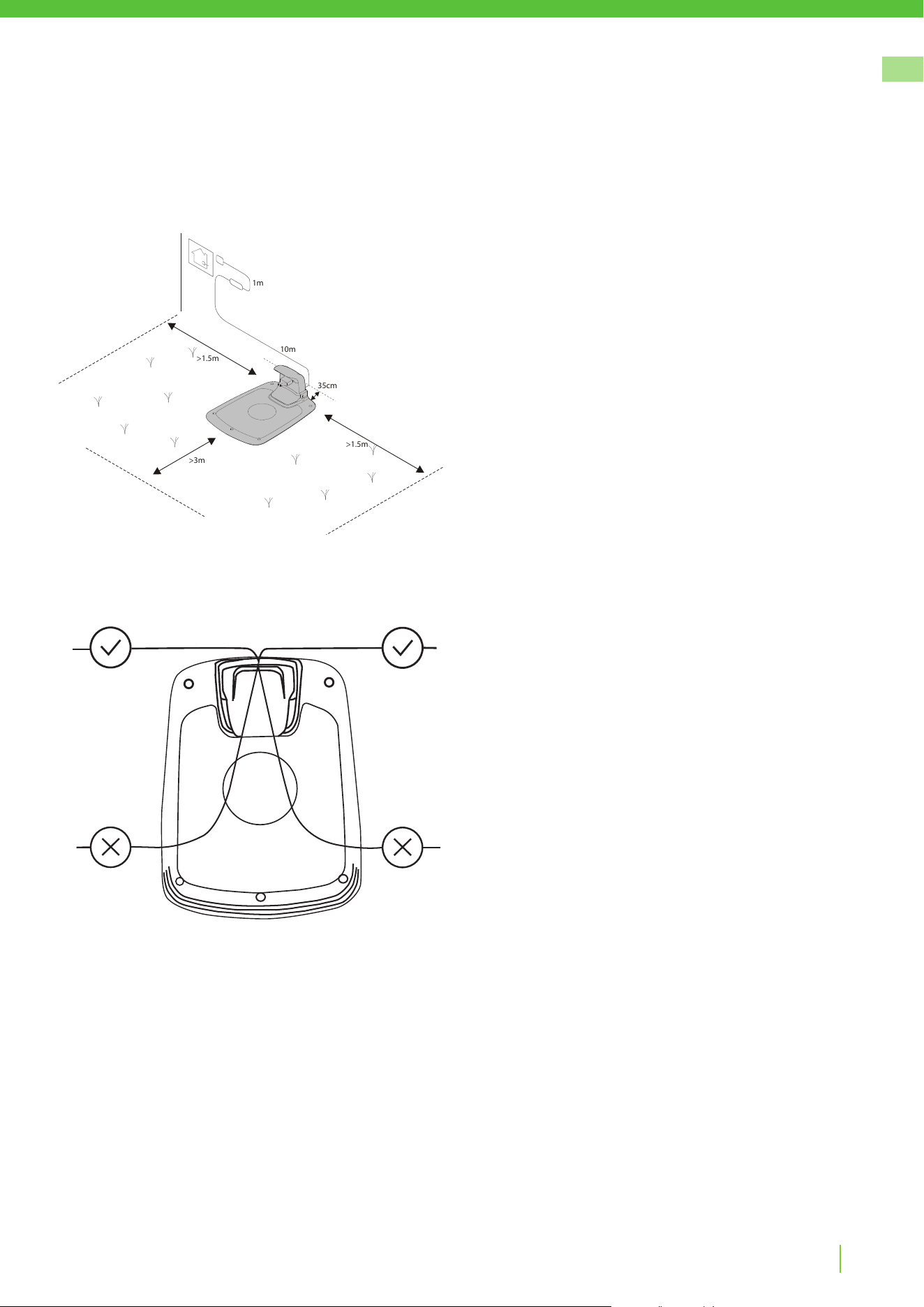
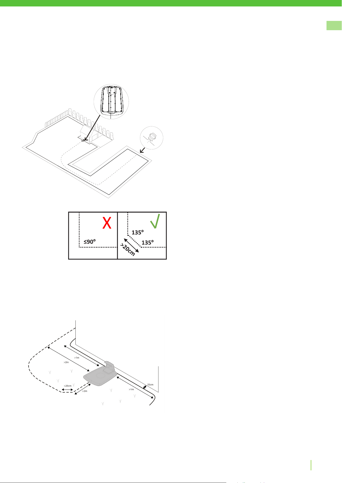
The entire charging station must be inside the operating area as shown
in the gure.
Installation
Position for the charging station as follows:
• In a level spot out of direct sunlight
(The front end of the charging station must not be 5 cm higher or
lower than the back end.)
• Within reach of a wall socket
(The low voltage cable is 10 m long.)
• With at least 3 m in front of it and 1.5 m to each side
(Do not position in conned spaces in the operating area.)
INSTALLING AND CONNECTING THE CHARGING STATION
>1.5m
>1.5m
1m
>3m
10m
35cm
GREENWORKSTOOLS.EU
10
EN
Version 4 - 2023.09.22
CONNECTING THE POWER SUPPLY
Connect the power supply in a cool, dry environment; out of direct sunlight.
If the power supply is connected to an electrical socket outdoors, it must be approved for outdoor use.
The low voltage cable can cross the operating area if it is stapled down.
CAUTION: Do not cut, splice, or alter the low voltage cable. Altering the low voltage cable will void the
product guarantee.
Installation
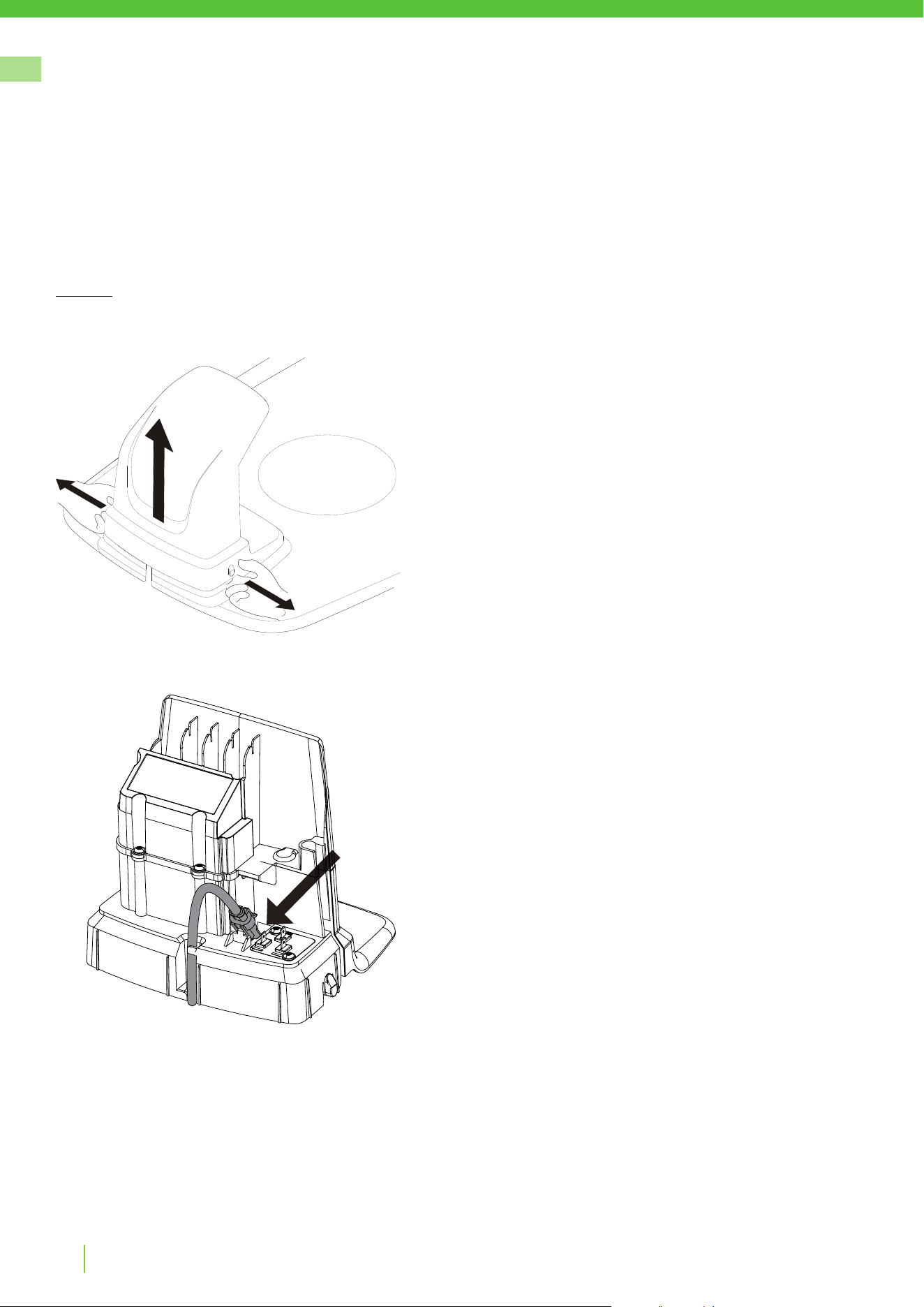
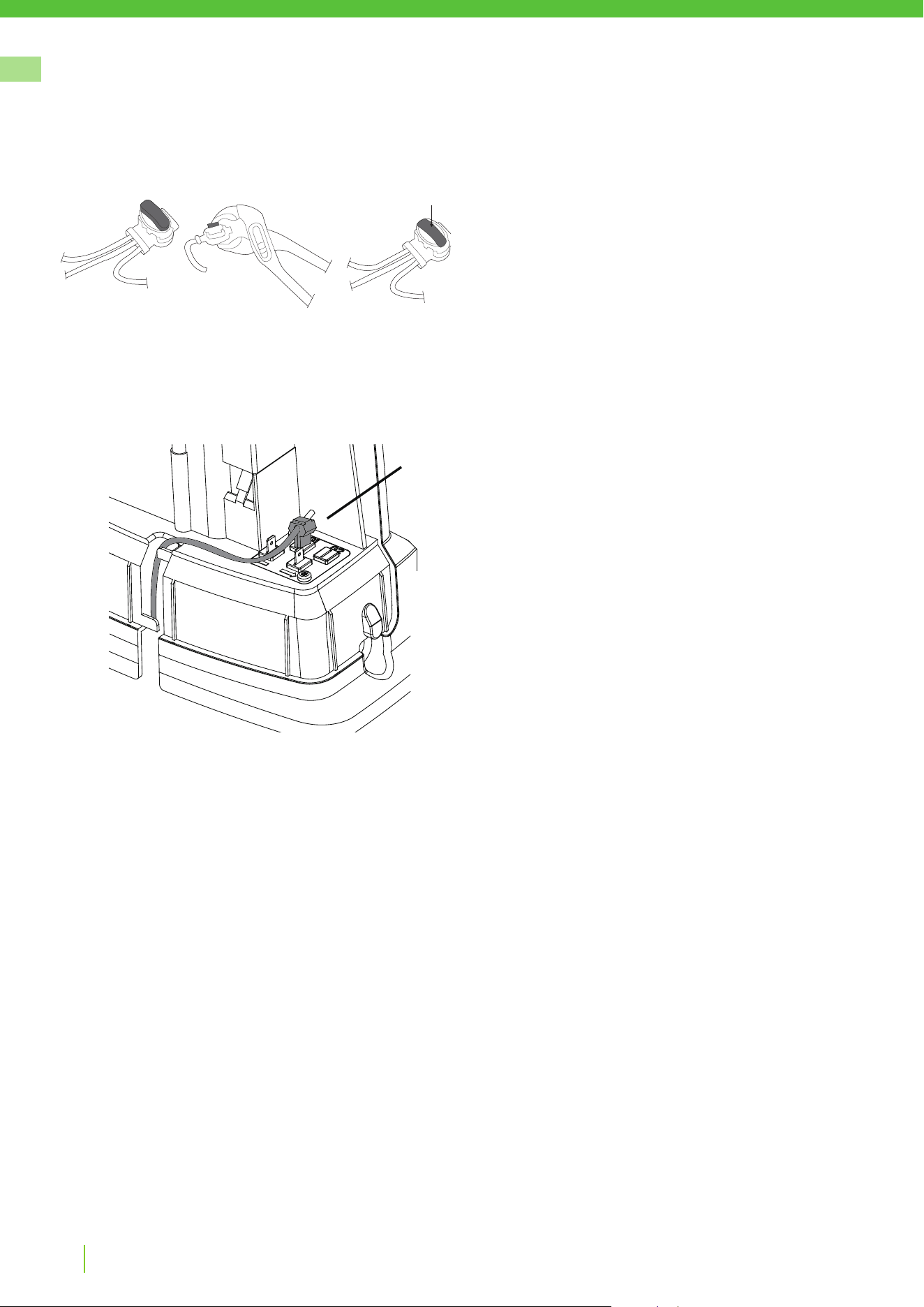
Connect the low voltage cable to the charging station.
Thread the low voltage cable behind the tabs to hold it in place in the
charging station.
Connect the power supply power cable to a 220-240 V wall socket.
Remove the protective cover on the charging station by pressing in the
tabs on each side of the base and lifting away the cover.
GREENWORKSTOOLS.EU
11
EN
Version 4 - 2023.09.22
Installation
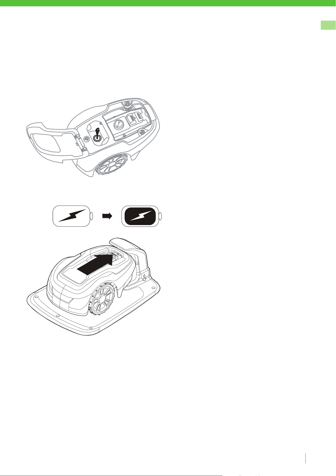
INITIAL CHARGING OF THE BATTERY
Insert the safety key into the mower and turn to the ON” ( | ) position.
Place the mower into the charging station while the boundary
and guide wires are being laid.
The mower cannot be used before the installation is complete.

GREENWORKSTOOLS.EU
12
EN
Version 4 - 2023.09.22
INSTALLING THE BOUNDARY WIRE
When installing the boundary wire there are a number of situations to consider as described in the table below.
Table 1. Handling Deviations and Obstacles in the Operating Area
VARIATION WITHIN OPERATING AREA BOUNDARY WIRE PLANNING
Fixed obstacles level with lawn that the mower can traverse (paving
stone paths or similar)
Lay the boundary wire under the paving stones or in the joint between
the paving stones.
Never run the mower over gravel, mulch, or similar material that can
damage the blades.
Fixed obstacles ± 1 cm high Lay the boundary wire 10 cm from the obstacle.
Fixed obstacles 1—5 cm high ,small ditches, ower beds, or low
kerbstones .
Lay the boundary wire 30 cm from the obstacle.
Fixed obstacles 5 cm or higher (fences or walls) Lay the boundary wire 35 cm from the obstacle.
Fixed obstacles taller than 15 cm that can withstand a collision (trees
or shrubs)
No measures required; the mower will turn around when it collides
with this type of obstacle.
Fixed obstacles that slope slightly such as stones or large trees with
raised roots
Lay the boundary wire 30 cm from or remove obstacle.
Fixed obstacles that cannot withstand a collision Lay the boundary wire 35 cm from and around the obstacle and then
return it back along the same route.
Long and narrow passages and areas narrower than 2.5 m Install a guide wire.
Borders on a slope, road, precipice, or water Supplement the boundary wire with a physical barrier at least
15 cm high.
Slope up to 30% within operating area No measures required; the mower can operate up to a 30% as long
as the slope is not at the boundary of the operating area.
Slope less than 15% at operating area edge Lay boundary wire as normal.
Slope greater than 15% at operating area edge Do not lay boundary wire unless a xed obstacle (fence or wall)
exists to prevent the mower from leaving the operating area.
When a part of the operating area outer edge slopes more than
15%; lay the boundary wire 20 cm in on the at ground before the
beginning of the slope.
NOTE: Slope gradient is dened in percentage units (%). The slope as a percentage unit is calculated as the dierence in elevation in centimetres
for every metre. If, for example, the dierence in elevation is 10 cm, the slope gradient is 10%.
Installation
GREENWORKSTOOLS.EU
13
EN
Version 4 - 2023.09.22
Installation
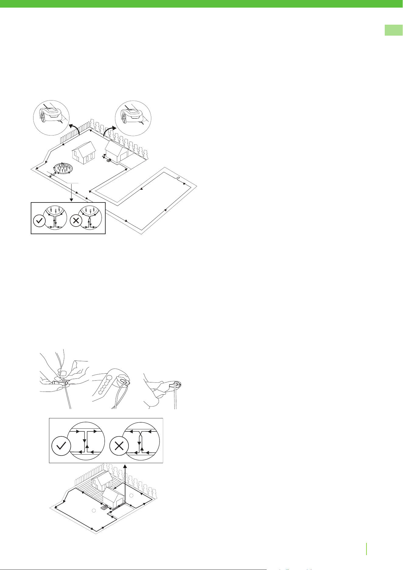
Temporarily secure the end of the loop wire to a peg or other object at
the charging station.
Lay out the loop wire in a counter-clockwise direction alone the planned
boundary of the operating area taking into consideration the rules in
Table 1 until you return to the charging station.
To isolate xed objects that cannot withstand a collision like bushes and
ower beds, make an island around it by lay the boundary wire starting
from the border nearest the object and go around the object and then
return it back along the same route. If wire installed counterclockwise
around the lawn, shall it be installed clockwise around the island
according to the picture. The two incoming and outgoing wire shall be
close to each other under the same wire peg.
If you are going to install a guide wire, create an eyelet with about 20
cm of extra boundary wire at the point where the guide wire will later
be connected.
See Installing a Guide Wire on page 15 for more information.
If the boundary wire is too short, use provided splice and guide wire
connectors to splice additional boundary wire as follows:
1 Insert both ends of the boundary wire into the splice and guide
wire connector. Check that the wires are fully inserted into the
splice and guide wire connector so that the ends are visible
through the splice and guide wire connector.
2 Squeeze down the button on top of the splice and guide wire
connector fully using a pliers wrench until you hear a click.
Lay down the loop wire reel at the charging station.
Go back around the boundary of the operating area and secure the
boundary wire either using pegs or buried in the ground. Pegs are
recommended since this allows for adjustment during the rst few
weeks of operation.
When securing the boundary wire with pegs:
• Cut the grass very low with a standard lawnmower or a trimmer
where the wire is to be laid.
• Lay the boundary wire on the ground and secure with pegs
close together.
• Push or hammer the pegs into the ground.
Do not push the pegs so far into the ground so that they strain the
boundary wire.
When burying the boundary wire:
• Bury the boundary wire 1—20 cm into the ground.
When the boundary wire is completely laid out and secured, install end
loop wire connectors as follows:
1 Open the loop wire connector and place the wire in the loop wire
connector grip.
2 Press the loop wire connectors together using a pliers wrench
until you hear a click.
Cut o any surplus boundary wire 1-2 cm above each connector.
If the lawn has a secondary area ② that is separated from the main
area ① where the charging station is placed, follow the steps below.
Lay the boundary wire starting from the border nearest the secondary
area and going around the area and then returning it back along the
same route.
If the wire is installed counterclockwise around the main area, it shall
be installed counterclockwise around the secondary area, according to
the picture. The two wires between the main area and the secondary
area shall be close to each other.
Note: The mower must be manually carried between the main area and
the secondary area.
1
2
30 cm
35 cm
0 cm
GREENWORKSTOOLS.EU
14
EN
Version 4 - 2023.09.22
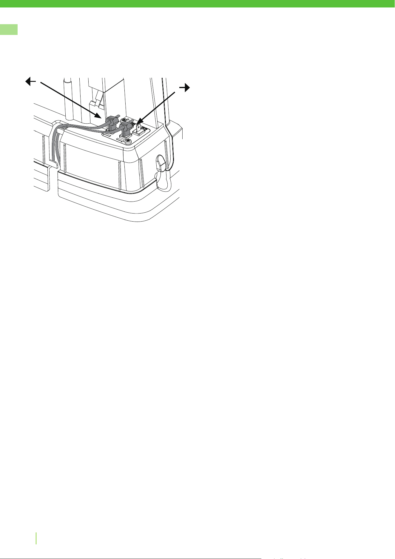
Connect the boundary wire to the charging station as follows:
1 Remove the protective cover on the charging station and thread
the wire behind the tabs into the channel at the rear of the
charging station.
2 Press the connector onto the metal pins on the charging station
(marked with left and right arrows).
NOTE: Make sure the boundary wire to the right of the charging station
is connected to the arrow pointing right and the same for the left side.
Installation
GREENWORKSTOOLS.EU
15
EN
Version 4 - 2023.09.22
Do not lay the guide wire closer than 30 cm from the boundary wire.
Do not lay the guide wire across the boundary wire.
Lay the guide wire straight under the charging plate in the track
intended for this and then at least 2 m straight out from the front edge
of the plate.
Leave as much space as possible to the left of the guide wire (as seen
when facing the charging station).
Use the same cable roll for both the boundary wire and the guide wire.
The guide wire, like the boundary wire, must be secured to the ground
with pegs or buried.
When installing the guide wire on a steep slope, lay the wire at an
angle to the slope so it is easier for the mower to follow the guide wire
on the slope.
Do not lay the guide wire at sharp angles or the mower will have
diculty following it.
INSTALLING A GUIDE WIRE
The mower uses the optional guide wire to nd its way back to the
charging station, but also nd hard-to reach areas of the operating area.
For example, the guide wire is laid between the charging station and a
remote part of the working area or through a narrow passage.
For narrow passages (less than 2.5 m) or to shorten search times, a
guide wire is recommended.
Plan the location of the guide wire before laying out the boundary wire.
Run the guide wire to the loop on the boundary wire where the guide
wire is to be connected.
Cut the boundary wire using the combination pliers.
Installation
GREENWORKSTOOLS.EU
16
EN
Version 4 - 2023.09.22
Installation
Insert both ends of the boundary wire as well as the end of the guide
wire into the splice and guide wire connector. Check that the wires are
fully inserted into the splice and guide wire connector so that the ends
are visible through the splice and guide wire connector.
Squeeze down the button on top of the splice and guide wire connector
fully using a pliers wrench until you hear a click.
Secure the splice and the boundary and guide wires either using pegs
or by burying.
Connect the guide wire to the charging station as follows:
1 Remove the protective cover on the charging station and thread
the guide wire behind the tabs into the channel leading to the
terminals.
2 Connect the guide wire to the contact pin on the charging station
that is labelled G1.
G1
GREENWORKSTOOLS.EU
17
EN
Version 4 - 2023.09.22
Pair the mower with Mobile App as instructed in Pairing Mobile App
to Mower on page 19.
Installation
Check the LED indicator on the charging station:
• LED indicator lights up continuously green, if the output voltage
of the power supply is available and the boundary wire is not
interrupted.
The LED indicator does not light up when the output voltage of the
power supply is not available.
If the indicator LED does not show a solid or green light, see Indicator
LEDs on the Charging Station on page 24 for troubleshooting.
CALIBRATING AND INITIAL START UP
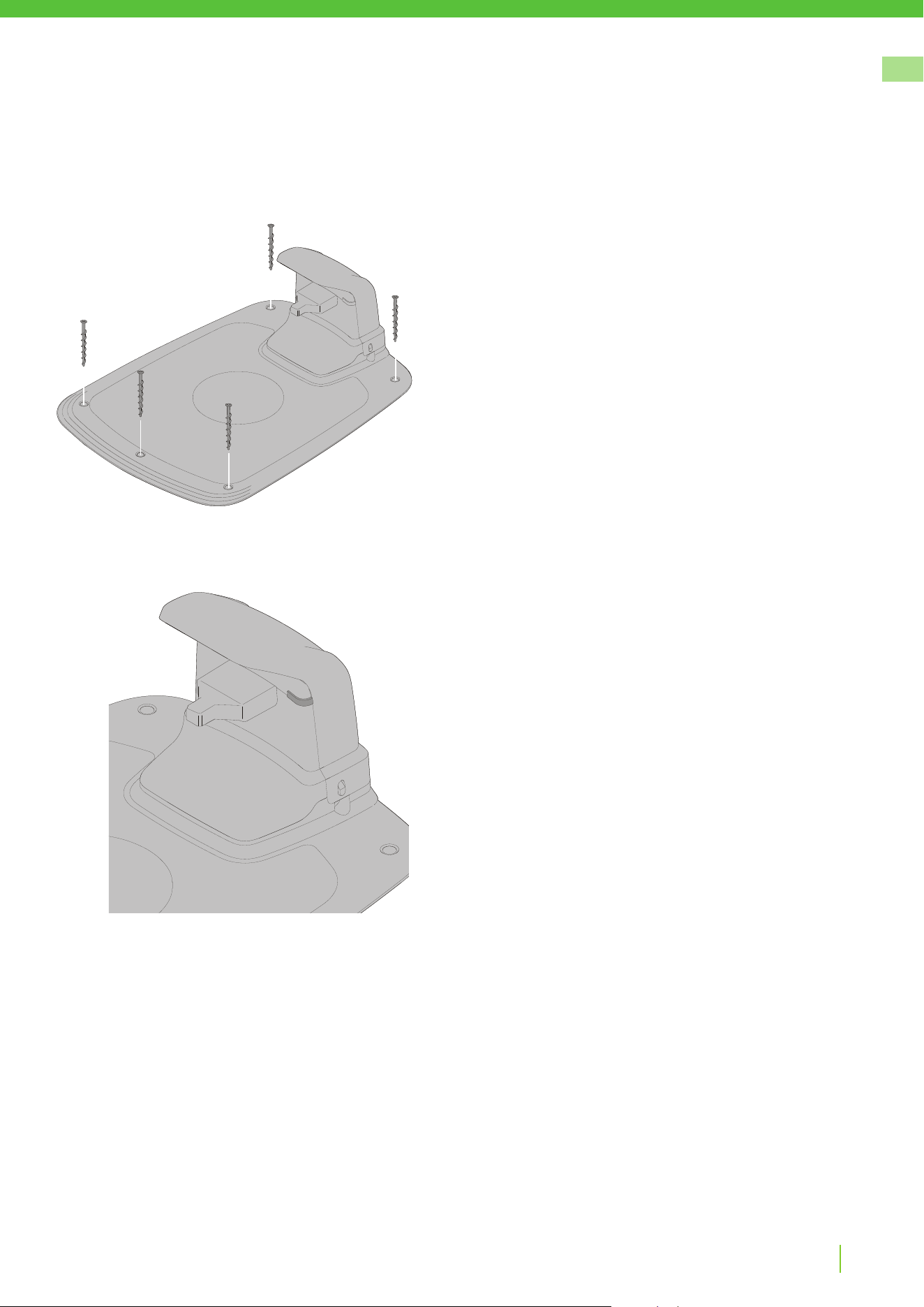
Secure the charging station to the ground using the ve supplied xing
screws using a 6 mm hex key.
NOTE: Do not make new holes in the charging station base plate. Only
the existing holes may be used to secure the base plate to the ground.
NOTE: Do not step or walk on the charging station base plate.
GREENWORKSTOOLS.EU
18
EN
Version 4 - 2023.09.22
Operation
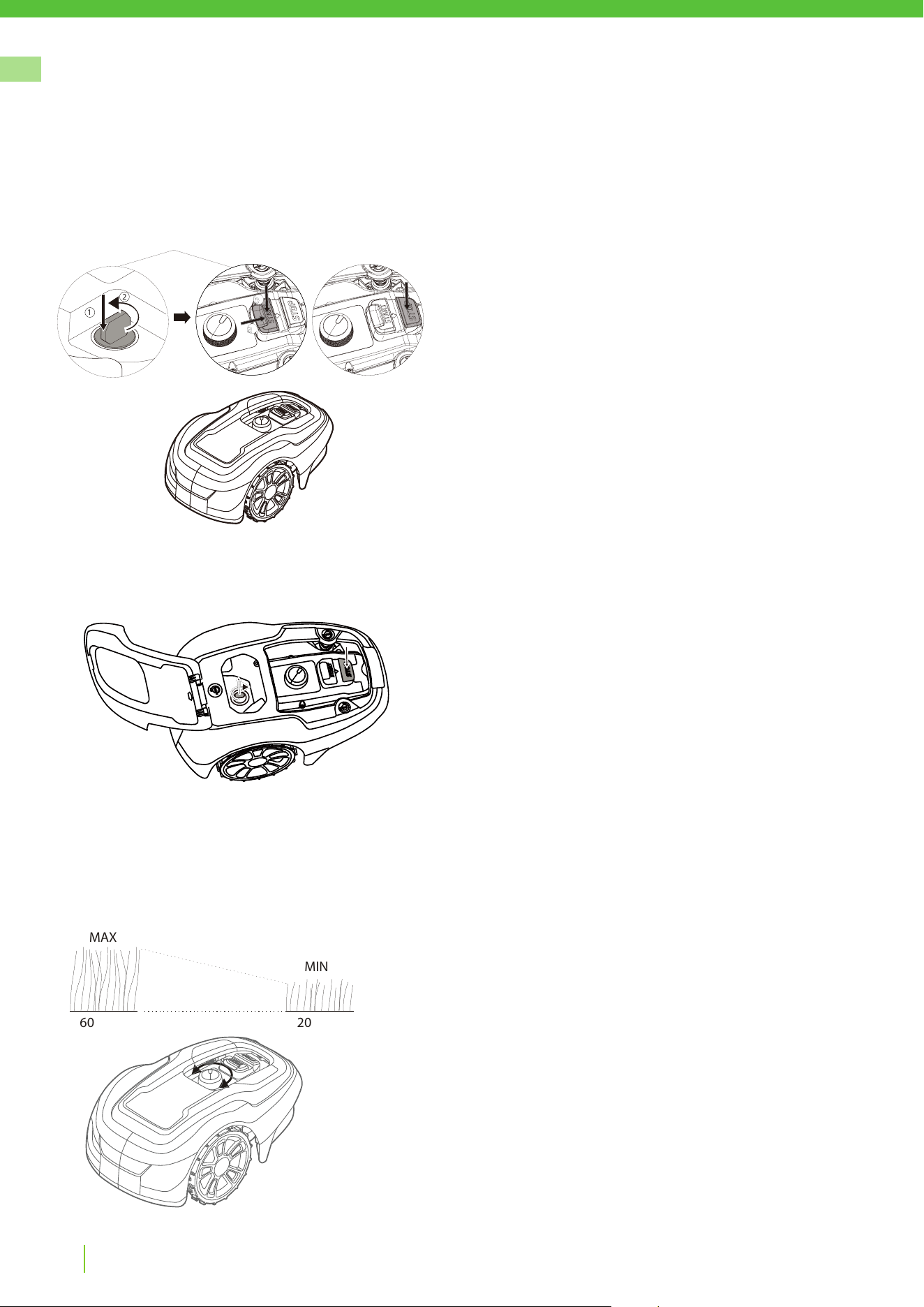
STARTING AND STOPPING THE MOWER
To start the mower:
1 Insert the safety key and rotate counter clockwise to position ”1”.
2 Slide the START button latch backwards.
3 Press down the START button.
To stop the mower:
Press the STOP button on the mower.
SWITCHING OFF THE MOWER
Press the STOP button on the mower and remove the safety key.
WARNING! Always remove the safety key when performing
maintenance or if the mower must be moved.
ADJUSTING CUTTING HEIGHT
For the rst few weeks of mowing, set the cutting height to 60 mm to
avoid cutting the boundary wire and guide wire. Lower the setting one
step each week thereafter until the desired cutting height is reached.
Turn the cutting height adjustment knob to the required setting. The
selected setting is the marking on the body that aligns with the arrow
on the knob.
Turn clockwise to increase the cutting height.
Turn anti-clockwise to decrease the cutting height.
The cutting height for the mower can be adjusted between 20 mm and
60 mm.
MAX
60
20
MIN
Start Stop
b
a
1
2
GREENWORKSTOOLS.EU
19
EN
Version 4 - 2023.09.22
PAIRING MOBILE APP TO MOWER
Download Greenworks tools App from App Store/Google Play and follow the on-screen instructions for how to
pair the mower. Have the unique pairing code (found on the quick guide manual) and the mower at hand.
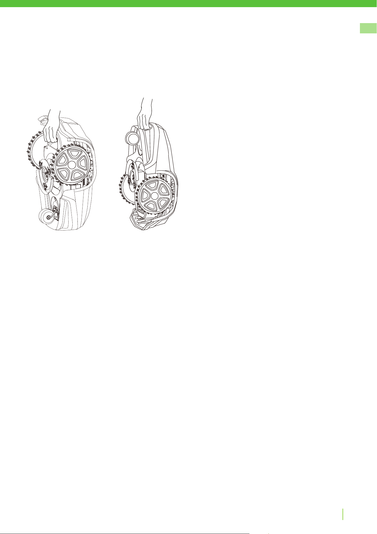
LIFTING AND CARRYING THE MOWER
Press the STOP button and remove the safety key before lifting.
Always lift the mower using the carrying handle.
Operation
GREENWORKSTOOLS.EU
20
EN
Version 4 - 2023.09.22
WARNING! Wear protective gloves when handling or working near the sharp blades.
WARNING! Before working on the mower itself, remove the safety key.
WARNING! Before working on the charging station or power supply, remove the plug from
the mains.
• Periodically visually inspect the mower and replace worn or damaged parts for safety.
• Inspect that the blades rotate freely
• Keep all nuts, bolts, and screws tight to be sure that the mower is in safe working condition.
• The normal operating life of the blades is 2 to 6 weeks when used at maximum area capacity and longer
for smaller areas.
CAUTION: Dull blades result in the grass being cut poorly; requiring more energy and shorter time between
battery loadings.
• Clean the mower regularly for best function.
Maintenance
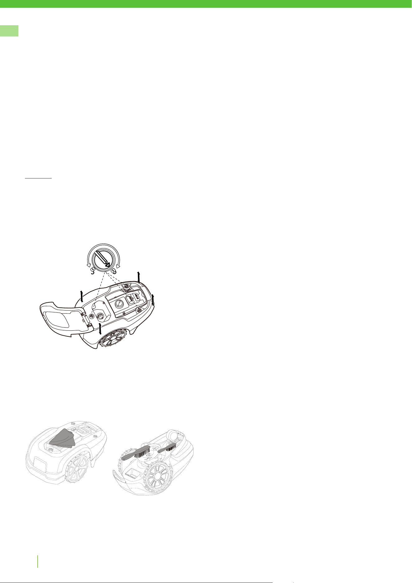
REMOVING THE BODY FROM CHASSIS
Rotate the knob to the unlock position and lift rmly at one of the
corners of the body and repeat for all four corners, until the body pops
loose from the chassis.
Replace the body by aligning the body onto the chassis and press down
rmly until you hear the click. Rotate the knob to the lock position.
Check that the body is rmly attached to the chassis.
CLEANING
WARNING! Press the STOP button and remove the safety
key before cleaning.
Clean the exterior of the mower thoroughly using a soft brush, damp
cloth, and low pressure water hose, if necessary. Remove the body
from the chassis.
Turn the mower on its side and clean the blade area and wheels with a
sti brush or scraper to remove compacted grass clippings.
GREENWORKSTOOLS.EU
21
EN
Version 4 - 2023.09.22
Maintenance
MAINTAINING THE BATTERY
WARNING! In the event of electrolyte leakage, ush
with water/neutralizing agent and seek medical care if
electrolyte comes in contact with the eyes.
Only charge the battery in the original charging station. Incorrect use
may result in electric shock, overheating, or leakage of corrosive liquid
from the battery.
The battery is maintenance-free, but has a limited service life of 2 to
4 years depending on the length of the season and how many hours a
day the mower is used.
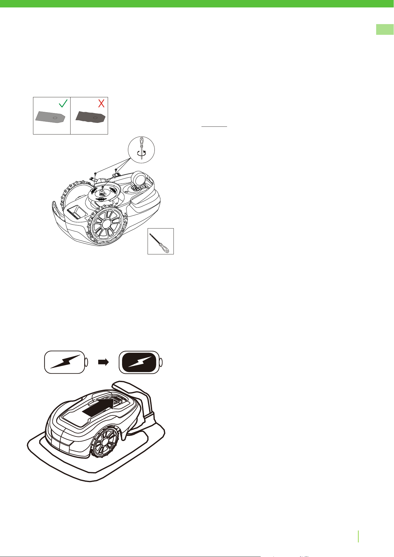
REPLACING BLADES
WARNING! Press the STOP button and remove the safety
key before replacing blades and wear protective gloves.
WARNING! Use only GLOBE’S blade: 333092355
CAUTION: Use only original replacement parts.
Replace all three blades and screws as a set at the same time.
Turn the mower upside down.
Loosen the screws using a straight slot or cross tip screwdriver.
Remove the blades and the screws.
Screw in the new blades using new screws.
Check that the blades pivot freely
cross tip screwdriver

GREENWORKSTOOLS.EU
22
EN
Version 4 - 2023.09.22
WINTER STORAGE MOWER
Always clean the mower before winter storage.
Charge the battery fully before winter storage.
CAUTION: If the battery is not fully charged, it can be damaged and in certain cases be rendered useless.
Inspect the condition of wear items; that the blades are sharp and that blades and front wheels turn freely.
Correct any deciencies.
Store the mower in a dry, frost-free environment standing on all four wheels.
WINTER STORAGE CHARGING STATION
When possible, disconnect the boundary wire and guide wire from the charging station and store the charging
station and power supply indoors.
Leave the boundary wire and the guide wire in the ground, but protect the ends of the wires from dampness
by connecting them to an original coupler or putting them in a container with grease.
If it is not possible to store the charging station indoors, the charging station must remain connected to the
mains, the boundary wire, and the guide wires.
AFTER WINTER STORAGE
Inspect the mower and charging station contact and charging strips for corrosion, burning, or lth. If the
charging or contact strips require cleaning, clean using ne grade emery cloth.
Maintenance

GREENWORKSTOOLS.EU
23
EN
Version 4 - 2023.09.22
Troubleshooting
INDICATOR LEDS ON CHARGING STATION
LED STATUS MEANING ACTION
Green On Boundary wire and Charging station OK No action required.
Blue Flashing Boundary wire broken or not connected Check and repair boundary wire.
Red Flashing Electronic fault in charging station or power supply Unit Please contact your dealer
This section also presents some symptoms that can guide you if the mower does not work as expected.
INDICATOR LEDS ON MOWER
LED STATUS MEANING ACTION
1. Operating
(Green)
Flashing Recovery mode Place the robot in charging station with a
mobile with the GreenGuide App close to the
mower for software update of mower. This can
take up to 1 hour until the green LED to stop
ashing. If LED doesn’t stop ash then restart
the robot outside the CS and try again.
On Mower in operation mode (charging, parked in Charging
station, paused, mowing or searching)
O Mower stopped with Stop button on mower, safety key in
Disabled position, mower in error state or mower waiting
for PIN code.
2. Connectivity
(Blue)
Flashing Mower not ready for Bluetooth connection If mower stopped with error the mower need
to be restarted with the Start button to allow
Bluetooth connection again
On Mower ready for Bluetooth connection with Mobile App
O Mower not in ”Power on mode”
3. Security
(Yellow)
Flashing PIN code authorization required ... via Mobile App.
O No pin required No action required
4. Error
(Red)
Flashing Mower stopped with error Check the reason for the error and then restart
by pressing the Start button on the mower.

GREENWORKSTOOLS.EU
24
EN
Version 4 - 2023.09.22
SYMPTOMS
If your mower does not work as expected, follow the troubleshooting guide below.
SYMPTOMS CAUSE ACTION
Mower has diculty
docking with charging
station
The charging station is on a slope. Place the charging station on a surface that is entirely
level. See Installing and connecting the Charging
Station on page 9.
The boundary wire is not laid correctly in relation to
the charging station.
Check that the charging station and boundary wire
has been correctly installed. See Installing and
connecting the Charging Station on page 9.
Uneven mowing results The mower works too few hours per day. Increase the operation time. See the Scheduling
function in the Mobile App.
The shape of the working area requires manual
settings to be made for the mower to nd its way to
all remote areas.
Adjust lawn coverage to steer the mower to one or
more remote areas. See Settings function in the
Mobile App.
The shape of the working area requires manual
settings to be made for the mower to nd its way to
all remote areas.
Try limiting the operating area or extending the
operation time. See the Scheduling function in the
Mobile App.
The blades are dull. Replace all the blades and screws so that the rotating
parts are balanced. See Replaceing blades on page
21.
Grass collects on the blade disc or around the motor
shaft.
Check that the blade disc rotates easily. If not,
remove grass and foreign objects. See Maintenance
on page 20.
The mower mows for
shorter periods than usual
between charges
Grass or other foreign object are blocking the blade
disc.
Remove grass and foreign objects. See Maintenance
on page 20.
The battery is worn out. Contact a service workshop to replace the battery.
Mowing and charging times
shorter than usual
The battery is worn out. Contact a service workshop to replace the battery.
BREAKS IN BOUNDARY WIRE AND GUIDE WIRE
Breaks in the boundary wire and guide wire (if installed) are usually the result of unintentional physical damage.
Inspect the entire boundary wire from the charging station and back.
Inspect the guide wire (if installed) from the charging station to the splice into the boundary wire.
Inspect that all the couplings have been properly squeezed to make connections.
Troubleshooting

GREENWORKSTOOLS.EU
25
EN
Version 4 - 2023.09.22
Technical Data
Optimow 4 Optimow 5 Optimow 7 Optimow S Optimow M
Dimensions:
Height 25 cm 25 cm 25 cm 25 cm 25 cm
Length 57 cm 57 cm 57 cm 57 cm 57 cm
Width 36 cm 36 cm 36 cm 36 cm 36 cm
Weight 7.2 kg 7.2 kg 7.2 kg 7.2 kg 7.2 kg
Electrical system:
Battery, Special Lithium-Ion battery 20 V / 2.0 Ah,
Part No.
T0100110-00 /
T0100608-00
20 V / 2.0 Ah,
Part No.
T0100110-00 /
T0100608-00
20 V / 2.0 Ah
Part No.
T0100110-00 /
T0100608-00
20 V / 2.0 Ah,
Part No.
T0100110-00 /
T0100608-00
20 V / 2.0 Ah,
Part No.
T0100110-00 /
T0100608-00
Power supply 220-240 V/32
VDC
220-240 V/32
VDC
220-240 V/32
VDC
220-240 V/32
VDC
220-240 V/32
VDC
Low voltage cable length 10 m 10 m 10 m 10 m 10 m
Mean energy consumption at
maximum use
5 kWh/month for
a working area of
450 m
2
6 kWh/month
for a working
area of 550 m
2
9 kWh/month
for a working
area of 750 m
2
4 kWh/month for
a working area of
300 m
2
6 kWh/month for
a working area of
500 m
2
Charge current 1.3 A DC 1.3 A DC 1.3 A DC 1.3 A DC 1.3 A DC
Average charging time 150 minutes 120 minutes 70 minutes 240 minutes 140 minutes
Average cutting time 60 minutes 60 minutes 60 minutes 60 minutes 60 minutes
Noise emissions: *)
Measured sound power noise level **) 58 dB (A) 58 dB (A) 58 dB (A) 58 dB (A) 58 dB (A)
Guaranteed sound power noise level 59 dB (A) 59 dB (A) 59 dB (A) 59 dB (A) 59 dB (A)
Sound pressure noise level ***) 47 dB (A) 47 dB (A) 47 dB (A) 47 dB (A) 47 dB (A)
Mowing:
Cutting system Three pivoted
cutting blades
Three pivoted
cutting blades
Three pivoted
cutting blades
Three pivoted
cutting blades
Three pivoted
cutting blades
Average power consumption during
cutting
25 W ± 20% 25 W ± 20% 25 W ± 20% 25 W ± 20% 25 W ± 20%
Cutting height 2-6 cm 2-6 cm 2-6 cm 2-6 cm 2-6 cm
Cutting width 17 cm 17 cm 17 cm 17 cm 17 cm
Narrowest possible passage 60 cm 60 cm 60 cm 60 cm 60 cm
Maximum slope for cutting area
30% 30% 30% 30% 30%
Maximum slope for boundary wire
15% 15% 15% 15% 15%
Maximum length boundary wire 800 m 800 m 800 m 800 m 800 m
Working capacity****) 450 m
2
550 m
2
750 m
2
300 m
2
500 m
2
Recommended area capacity 0 - 350 m
2
200 - 450 m
2
300 - 650 m
2
0 - 250 m
2
200 - 400 m
2
IP classication:
Mower IPX5 IPX5 IPX5 IPX5 IPX5
Charging station IPX3 IPX3 IPX3 IPX3 IPX3
Power supply IP67 IP67 IP67 IP67 IP67
*) The noise emission declarations conforms to EN 50636-2-107
**) uncertainties KWA, 1 dB (A)
***) uncertainties KPA, 1 dB (A)
****) Working capacity declaration conforms to EGMF RLM004-1.0/2016

GREENWORKSTOOLS.EU
26
EN
Version 4 - 2023.09.22
Technical Data
RADIO FREQUENCY DATA SHEET
Bluetooth
Short Range Devices (SRD)
(Boundary Wire)
Frequency Bands 2400.0-2483.5 MHz 0~148.5KHz
Power Class 7 dBm NA

GREENWORKSTOOLS.EU
27
EN
Version 4 - 2023.09.22
Environmental Protection
According to the European law 2012/19/EU, electrical and electronic equipment that is no
longer usable, and according to the European law 2006/66/EC, defective or used battery packs/
batteries, must be collected separately and disposed of in an environmentally correct manner.
The symbol on the mower or its packaging indicates that this product cannot be treated as
domestic waste. It should instead be left at a suitable recycling centre to recycle its electronic
components and batteries.
The batteries are enclosed in the chassis.
By ensuring that this product is taken care of correctly, you can help to counteract the potential
negative impact on the environment and people that can otherwise result through the incorrect
waste management of this product.
For more detailed information about recycling this product, contact your municipality, your
domestic waste service or the shop from where you purchased the product.
Separate collection of used machine and packaging let you recycle materials and use them
again. Use of the recycled materials helps prevent environmental pollution and decreases the
requirements for raw materials.
At the end of their useful life, discard batteries with a precaution for our environment. The
battery contains material that is dangerous to you and the environment. You must remove and
discard these materials separately at a equipment that accepts lithium-ion batteries.

GREENWORKSTOOLS.EU
28
EN
Version 4 - 2023.09.22
Warranty Terms
GLOBGRO AB, Globe Group Europe guarantees this product’s functionality for a period of three years (from
date of purchase), except for the battery that has two years warranty period. The guarantee covers serious
faults relating to materials or manufacturing faults. Within the guarantee period, we will replace the product or
repair it at no charge if the following terms are met:
• The mower and the charging station may only be used in compliance with the instructions in this operator
manual.
• Users or non-authorized third parties must not attempt to repair the product.
Examples of faults which are not included in the guarantee:
• Damage caused by lightning.
• Damage caused by improper battery storage or battery handling.
• Damage caused by using a battery that is not a original battery.
• Damage caused by not using original spare parts and accessories, such as blades and installation material.
• Damage to the loop wire.
The blades are seen as disposable and are not covered by the guarantee.
If a fault occurs with your mower, please contact the dealer for further instructions. Have your receipt and
product serial number to hand for quicker assistance.

GREENWORKSTOOLS.EU
29
EN
Name and address of manufacturer:
Name : Globe Technologies Europe GmbH
Address: Brunnenweg 17, 64331 Weiterstadt, Germany
Name and address of the person authorised to compile the technical le:
Name: Ralf Pankalla
Address: Brunnenweg 17, 64331 Weiterstadt, Germany
Here with we declare that the product:
Category: Robotic Lawnmower
Model: Optimow 4/5/7/M/S
Serial number: See product rating label.
Year of Construction See product rating label.
• is in conformity with the relevant provisions of the Machinery
Directive 2006/42/EC
• is in conformity with the provisions of the following other
directives:
• Electromagnetic Compatibility - Directive 2014/30/EU
• Radio equipment - Directive 2014/53/EU
• Low Voltage Directive 2014/35/EU
• Restriction of the Use of certain Hazardous Substances in
Electrical and Electronic Equipment (RoHS) Directive 2011/65/
EU & (EU) 2015/863
• Furthermore, we declare that the following standards have been
used:
•EN 60335-1, EN 50636-2-107, EN 60335-2-29,
•EN 62233, EN 55014-1, EN 55014-2, EN IEC 61000-3-2,
•EN 61000-3-3, EN 61558-1, EN 61558-2-16, EN 62311,
•EN 303 447, EN 300 328, EN 301 489-1, EN 301 489-3, EN 301 489-17,
•EN 62321-3-1, EN 62321-4, EN 62321-5, EN 62321-6,
•EN 62321-7-1, EN 62321-7-2, EN 62321-8
Ted Qu Haichao
Quality Director
Weiterstadt, 26.06.2021
Version 4 - 2023.09.22
CE Declaration of Conformity

GREENWORKSTOOLS.EU
30
EN
Declaration of Conformity (UK)
Name and address of manufacturer:
Name : Globe Technologies Europe GmbH
Address: Brunnenweg 17, 64331 Weiterstadt, Germany
Name and address of the Authorized representative:
Name: Garden Equipment Ltd
Address: First, Floor,3a Groveley Road, Christchurch, Dorset, BH23
3HB, UK
Name and address of the person authorised to compile the technical
le:
Name: Simon Del-Nevo
Address: First, Floor,3a Groveley Road, Christchurch, Dorset, BH23
3HB, UK
Here with we declare that the product
Category: Robotic Lawnmower
Model: Optimow 4/5/7/M/S
Serial number: See product rating label.
Year of construction: See product rating label.
• is in conformity with the relevant provisions of the Supply of
Machinery (Safety) Regulations 2008.
• is in conformity with the provisions of the following other UK
legislation:
Electromagnetic Compatibility Regulations 2016
Radio Equipment Regulations 2017
Electrical Equipment (Safety) Regulations 2016
The Restriction of the Use of Certain Hazardous Substances in
Electrical and Electronic Equipment Regulations 2012
Furthermore, we declare that the following standard have been used:
BS EN 60335-1, BS EN 50636-2-107, BS EN 60335-2-29,
BS EN 62233, BS EN 55014-1, BS EN 55014-2, BS EN 61000-3-2,
BS EN 61000-3-3, BS EN 61558-1, BS EN 61558-2-16, BS EN 62311,
EN 303 447, EN 300 328, EN 301 489-1, EN 301 489-3, EN 301 489-17,
BS EN 62321-3-1, BS EN 62321-4, BS EN 62321-5, BS EN 62321-6,
BS EN 62321-7-1, BS EN 62321-7-2, BS EN 62321-8
Place, date: Christchurch, Dorset, UK 07.06.2021
Signature: Ted Qu, Quality Director
Version 4 - 2023.09.22

GREENWORKSTOOLS.EU
31
EN
Version 4 - 2023.09.22