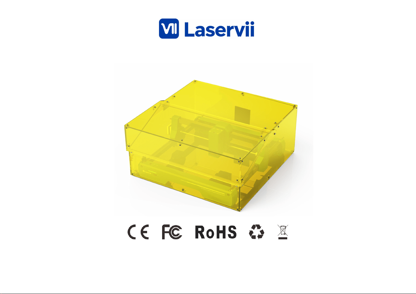
Note: The images are for reference only, the actual
product shall prevail.
Product Manual
L1 Pro 24W
A Letter to Customers
Dear Customer,
To ensure smooth assembly and use, we have prepared this assembly and operation guide manual.
Please read the following content carefully and follow the instructions to ensure safety and convenience
during use. If you encounter any issues, you can scan the WIKI QR code or visit the company website to
access relevant tutorial videos. If the machine malfunctions, please refer to the names of the
corresponding components and inform us of the problem and machine condition via the after-sales email
provided on this page.
After-sales em ail:service@l aservii.com
Official webs ite:https ://laservii .com/
Wiki:http s://wiki .laservii.com /en/hom e
Facebook
Official webs ite Wiki
Facebook: htt ps://ww w.facebook .com/profi le.php?id =615844 249182 07
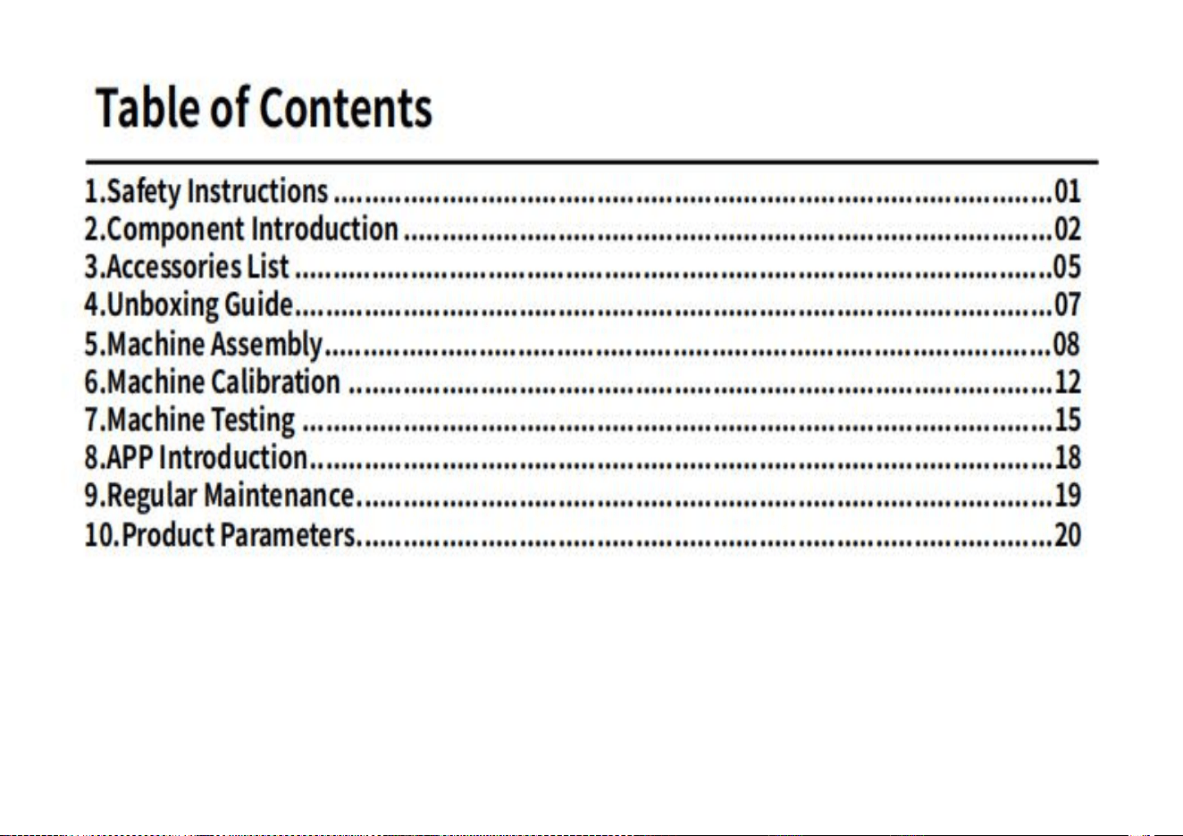
Table of Contents
1.Safety Instructions
2.Component Introduction
3.Accessories List
4.Unboxing Guide
5.Machine Assembly
6.Machine Calibration
7.Machine Testing
8.APP Introduction
9.Regular Maintenance
10.Product Parameters

Safety Instructions
1.Always wear specialized protective glasses matched to the laser type (e.g., 1064nm for fiber lasers). Do not operate the machine without
protection.
2.Strictly prohibit engraving PVC, foam, or chlorine-containing materials, as they produce highly toxic gases. Test unknown materials with an
1×1cm sample first.
3.Place the device on a stable surface with a load-bearing capacity ≥3 times the device weight. Leave ≥20cm of ventilation space around it, away
from children’s reach.
4.Turn on desktop ventilation or an external fan during engraving. For wood or leather processing, use an activated carbon filter box to reduce
odors and dust.
5.Before powering on, check that the power cord is undamaged, USB connections are secure, and the device is properly grounded. Avoid
touching power ports with wet hands.
6.Do not leave the station during operation. Press the emergency stop button for temporary pauses. Avoid touching the laser head’s path or
high-temperature workpieces.
7.Keep a small dry powder fire extinguisher in the work area. When engraving flammable materials (e.g., cardboard), reduce power and shorten
processing time.
8.Regularly clean lenses with anhydrous ethanol, wiping in one direction to avoid scratches. Always disconnect power before cleaning.
9.Do not operate after drinking, fatigue, or taking drowsiness-inducing medication. Do not remove safety covers for convenience.
10.In case of fire, cut power immediately and use the extinguisher. For laser eye burns, rinse with water and seek medical attention promptly.
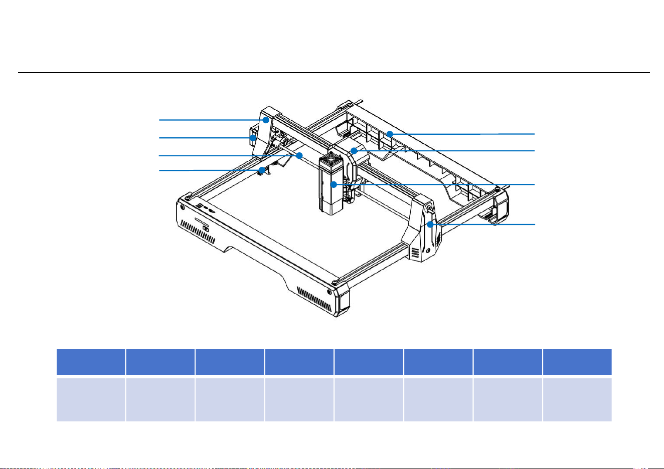
Component Introduction
1
3
5
6
7
8
2
1
2
3
4
5
6
7
8
Y-axis left
slider
Y-axis
motor
Optical
shaft
Y-axis limit
Rear frame
X-axis
slider
Laser
module
Y-axis right
slider
4
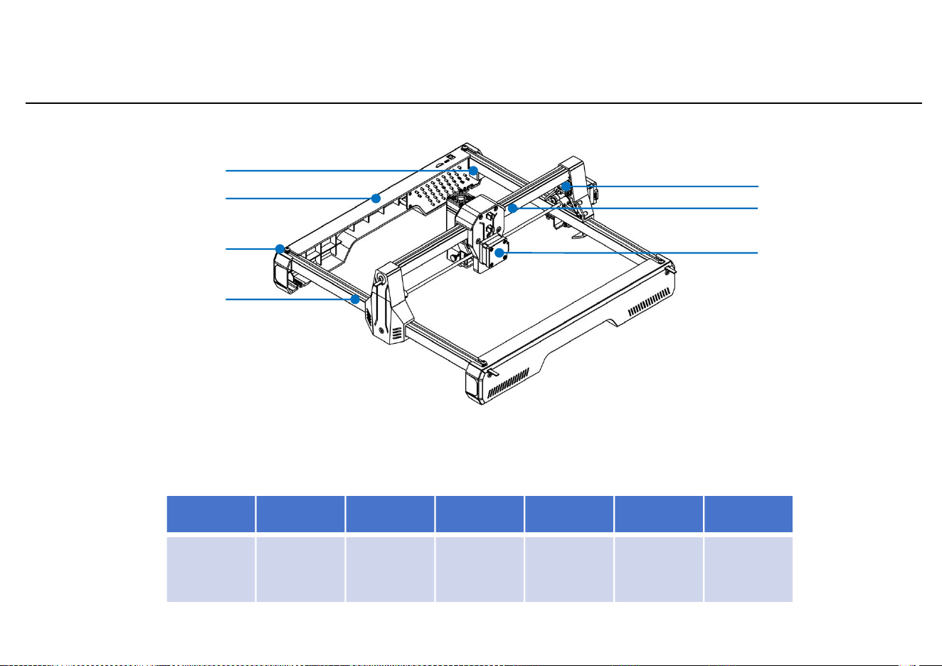
Component Introduction
1
3
4
5
6
7
2
1
2
3
4
5
6
7
Y-axis
limit
trigger
Front
frame
Belt
tensionin
g piece
Y-axis
profile
X-axis
limit
X-axis
profile
X-axis
motor
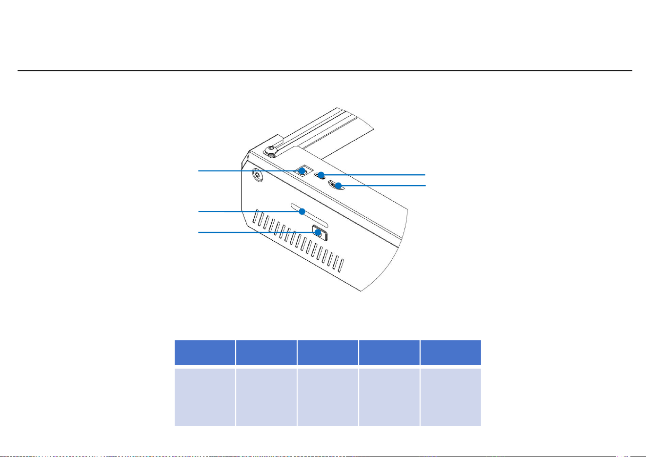
Component Introduction
1
3
4
5
2
1
2
3
4
5
DC socket
Silicone
light
guide
column
Power
button
Type-C
interface
TF card
slot
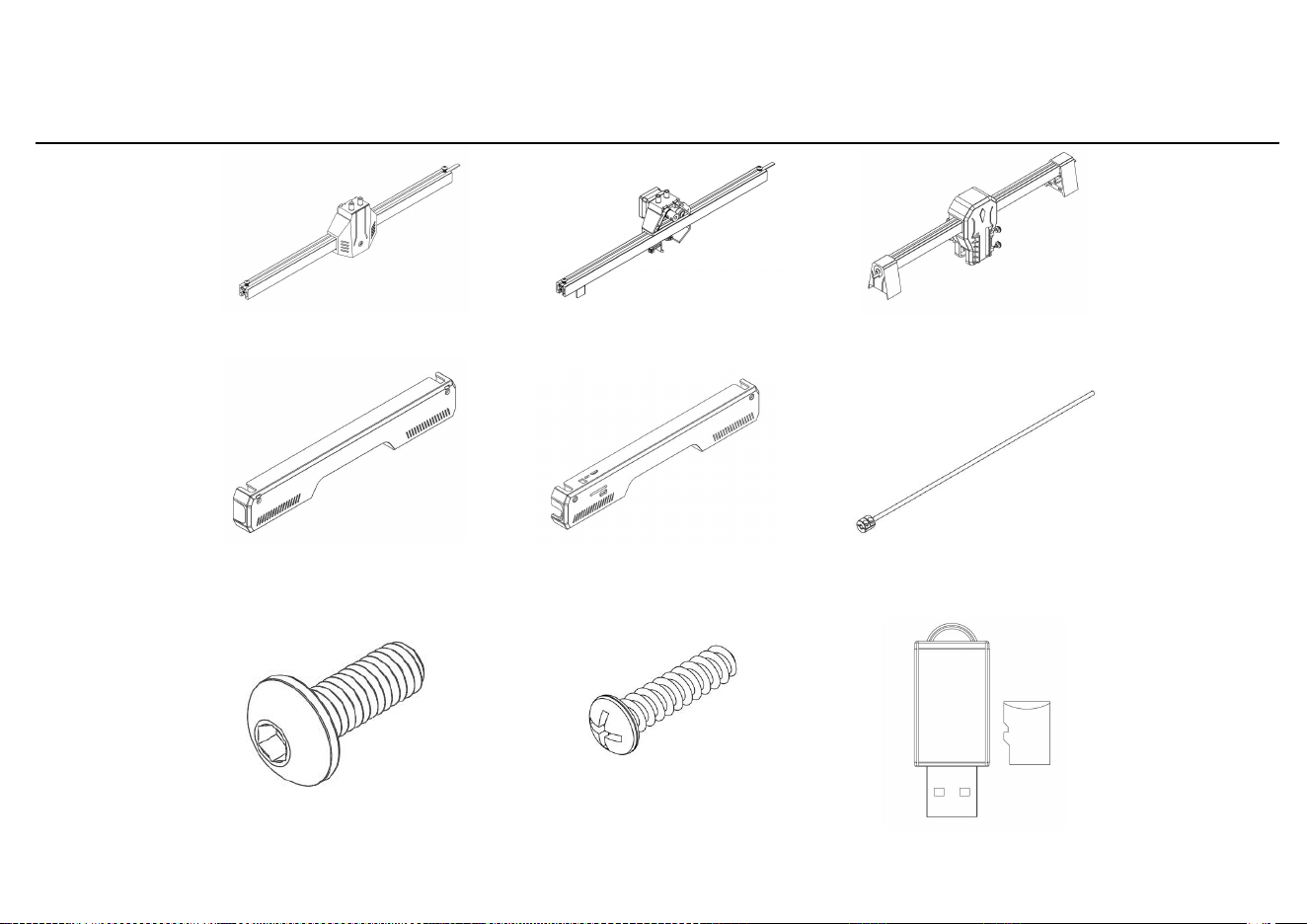
Y-axis right part X1
Y-axis left part X1
X-axis module X1
Front Frame X1
Rear Frame X1
Optical Axis Module
X1
Screw M5*12 X4
Self-tapping
screw
M3*10 X2
Accessories List
TF Card X1
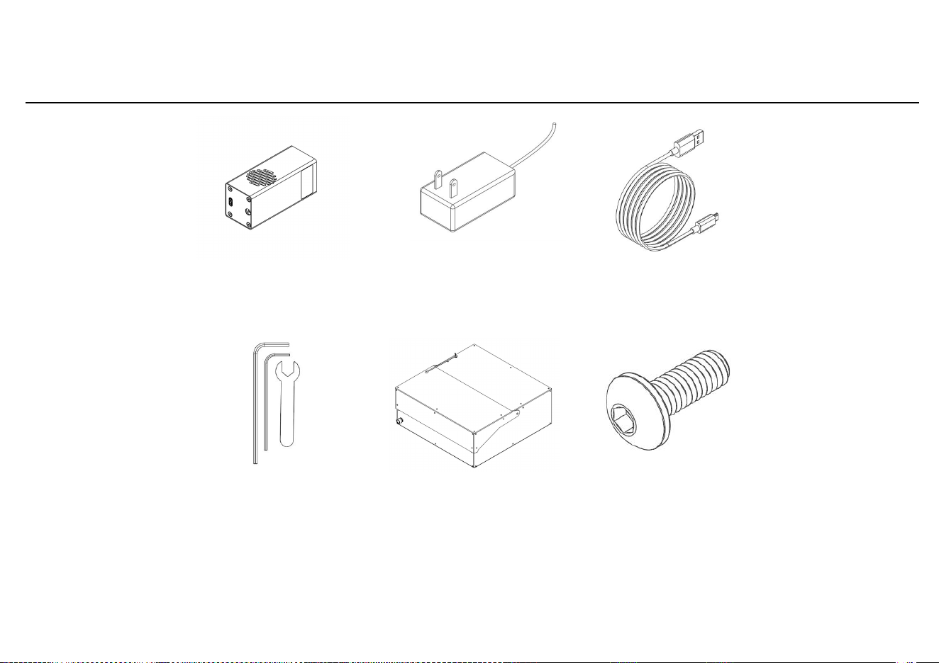
Laser module
24W X1
12V 3A/5A
Adapter X1
data line X1
Wrench Set
X1
Accessor y List
Housing X1
Screw M3*8 X8
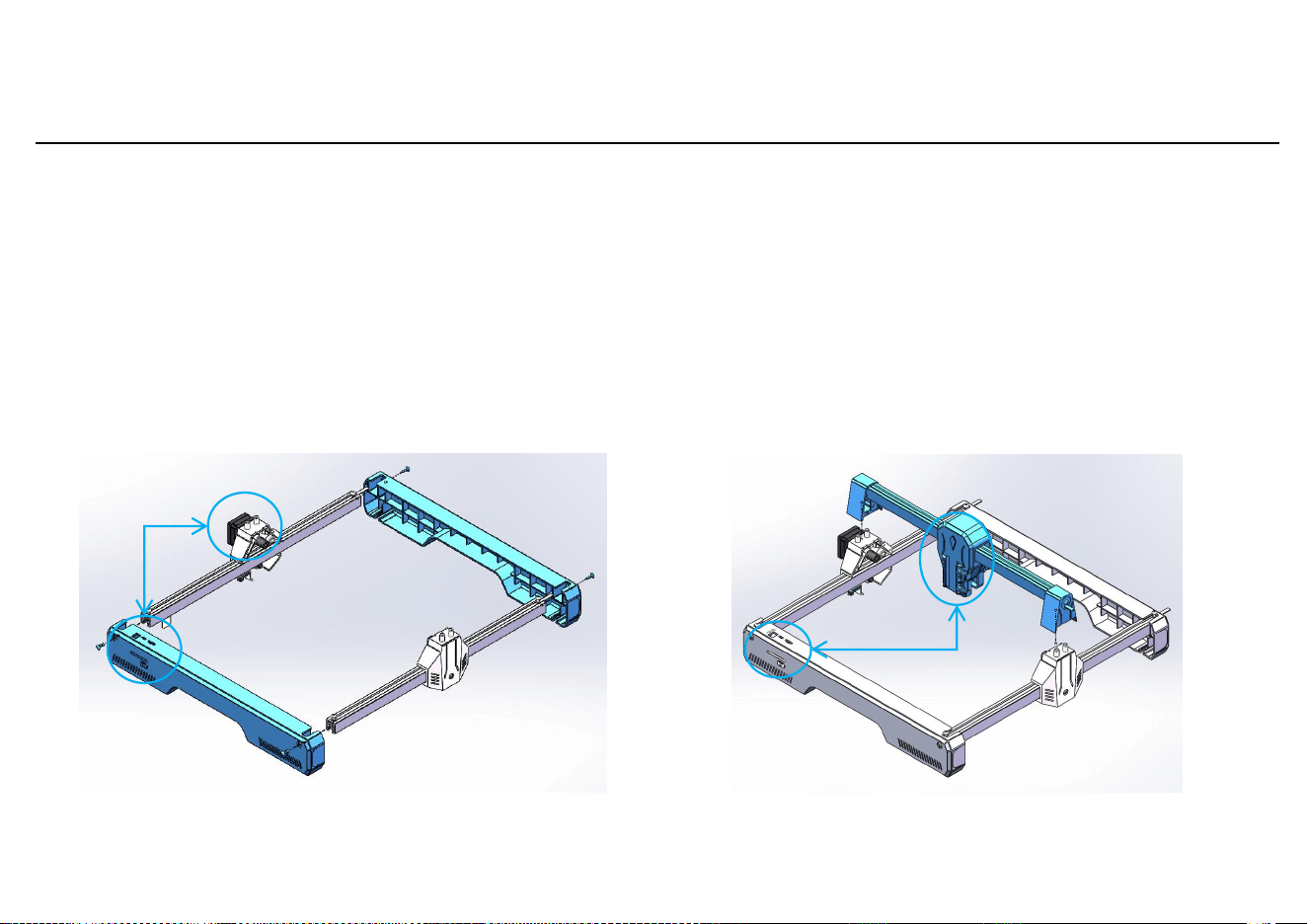
1. Front and Rear Frame A ssembly
Required materials:
Y-axis left part X1, Y-axis right part X1, front frame X1,
rear frame X1, Screw M5*12 X4.
Insert the front and rear frames into the slots of the Y-axis
left and right parts. Pass the M5 * 12 screws through the
frames and tighten them onto the profiles.
Note: The Y-axis left part
includes the motor.
2. X-axis Component A ssembly
Required materials:
X-axis component X1.
Align the X-axis front plate with the front
frame and press the X-axis component onto
the Y-axis left and right parts from top to
bottom.
Note: Confirm the direction of the X-
axis slider before pressing down.
Machine A ssembly
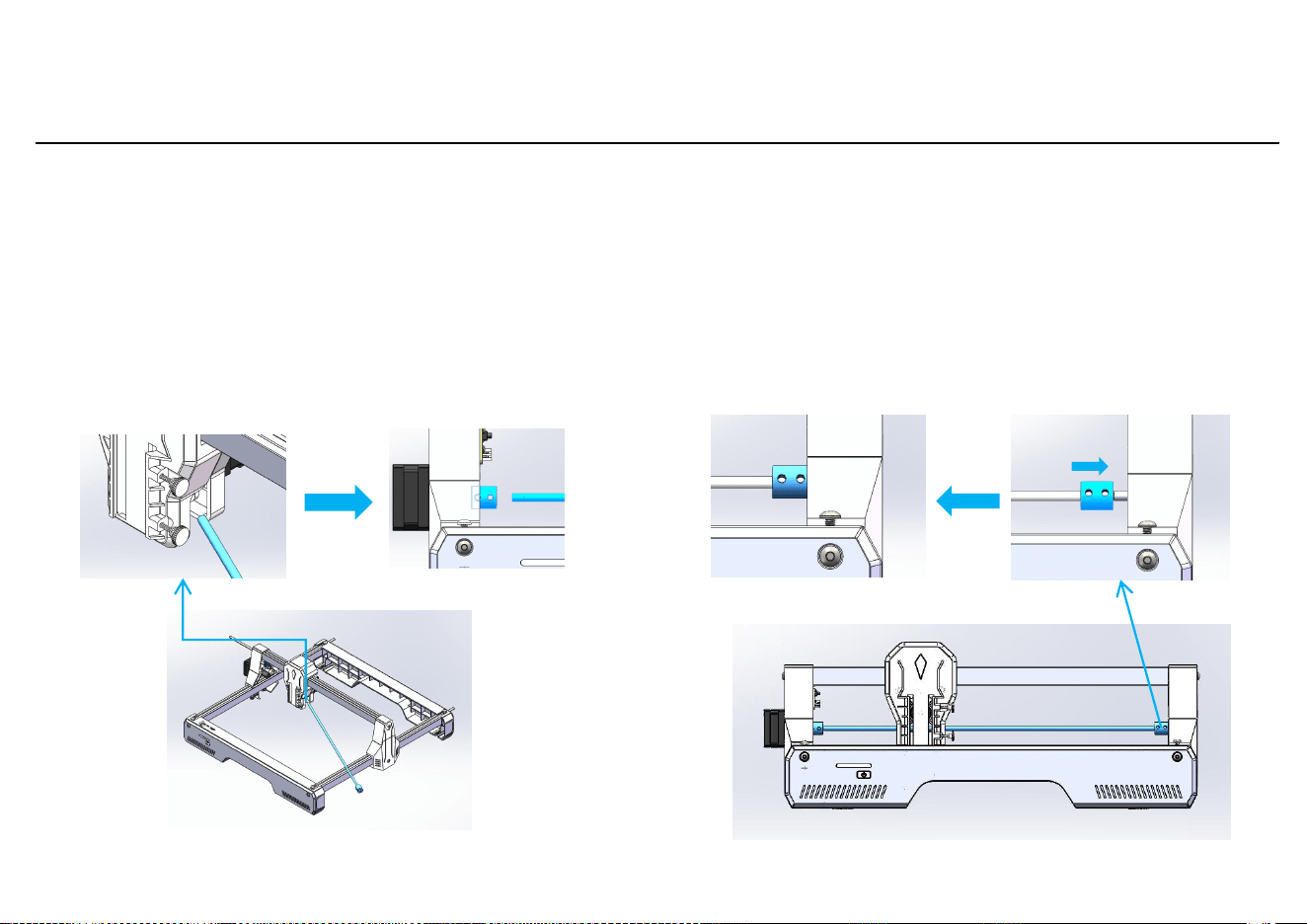
3. Optical Shaft Component Installation
Required materials:
Optical shaft component X1.
Pass the optical shaft component through
the hole under the X-axis slider and insert it
into the coupling on the Y-axis left part.
Tighten the two set screws on the coupling.
Loosen the set screws on the coupling at the
other end, push it to the right against the
synchronous pulley, and tighten the four set
screws on the coupling.
Machine A ssembly
Enlarge image1
Enlarge image2
Enlarge image3Enlarge image4
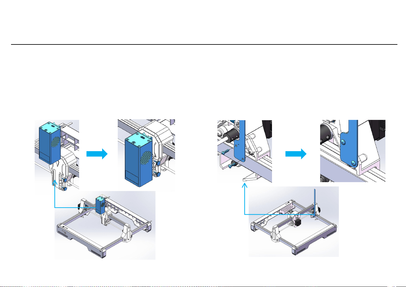
4. Laser Module Installation
5. Harness Mylar Sheet Assembly
Required materials:
Laser module 7W/12W
X1.
Required materials:
Self-tapping screw M3 * 10 X2.
Insert the laser module into the X-axis slide r from top
to bottom, then tighten the hand-tightened screw
from the side.
Use two M3 self-tapping screws to pass
through the Mylar sheet on the harness and
tighten it onto the Y-axis left part.
Machine A ssembly
Note: If the laser module is l ow, only tighten the
bottom hand-tightened screw.
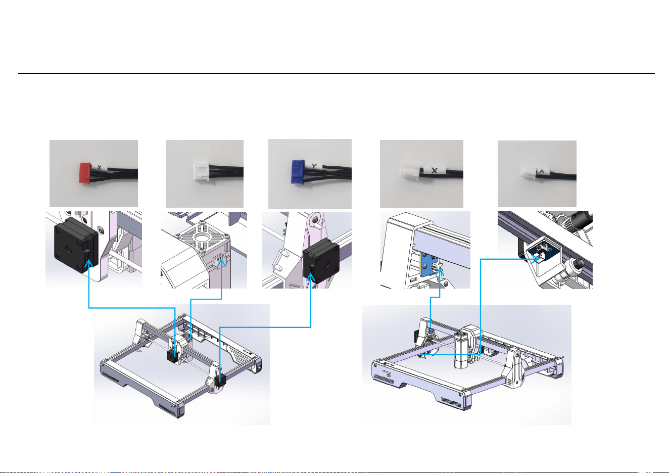
6. Wiring
X motor wire
Machine A ssembly
Y motor
wire
X limit
line
Y limit
line
Connect the wires from the motherboard harness to the corresponding positions on the machine as shown.
Laser
head wire
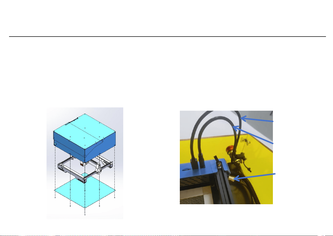
7. Housing Installation
8. Housing Wiring
Required materials:
Housing X1 Base Plate X1 Screws M3*8 X8
Place the housing over the machine from the to p,
then secure it to the housing by passing the M3*8
screws through the base plate from underneath.
As shown in the figure, use the cables to
connect the DC ports and Type-C ports of the
main board and the housing respectively.
Connect the emergency stop switch cable to
the wiring port of the main board.
Machine A ssembly
Required materials:
Type-C Cable X1 DC Cable X1
Type-C Cable
DC Cable
emergency sto p
switch cable
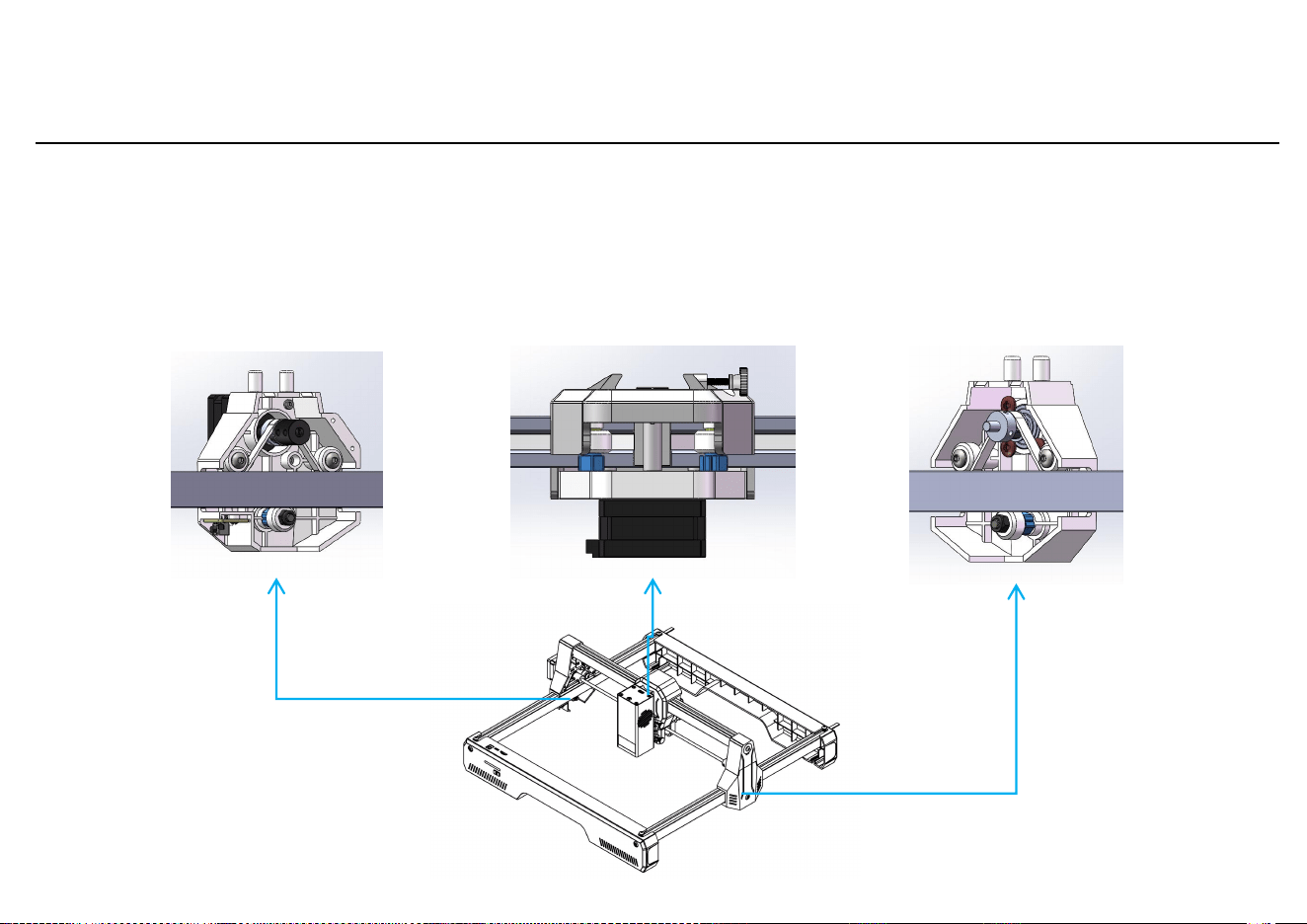
1. Eccentric Nut Adjustment
Machine Calibration
Check if the POM wheels on th e Y-axis left/rig ht parts and X- axis slider m atch the profile s and move
smoothly w ithout jamm ing.
Note:
1.Ideal state: When rotating the POM wheels, there should be slight friction with the profiles.
2.If the wheels spin without contact, adjust the eccentric nut with an open-end wrench.
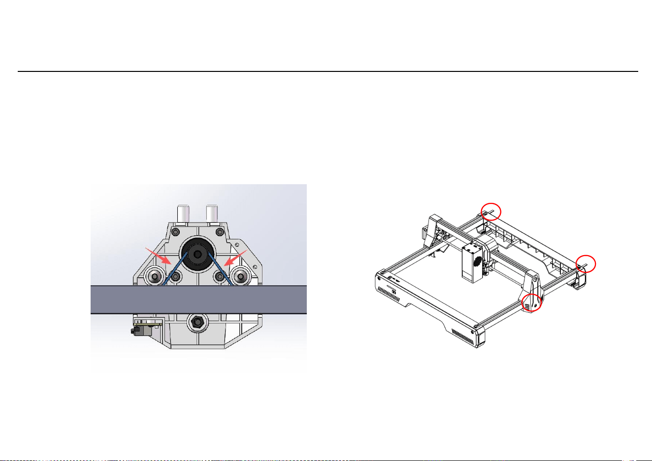
2. Synchronization Belt Adjust ment
Machine Calibration
Check the tight ness of the sync hronization b elts
on the Y-axis left /right parts a nd X-axis slid er.
Proper state: T he belt should be tight wh en
pressed at th e arrow-indi cated positi on.
Adjustment method: Loosen the
screws in the red box area,
tighten the belt, and then
retighten the screws.
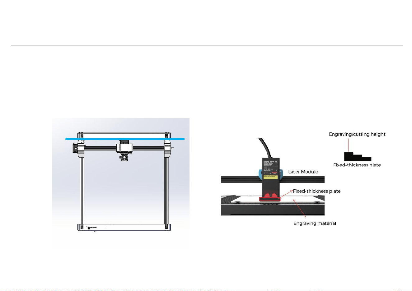
3. Y-axis Leveling
Machine Calibration
Push the X-axis component to the
rear of the machine, ensuring both Y-
axis plastic parts contact the rear
frame.
4. Laser Module Focusing
Ensure parallel
Machine Testing
1.Software Download
LaserGRBL is one of the most popular DIY laser engraving
software. Download it from http://lasergrbl.com/download(the
installer is also available on the TF card or USB drive
provided by the manufacturer).
Introduction: LaserGRBL is easy to use but only supports
Windows (Win XP/7/8/10). Mac users can choose LightBurn,
which is impressive but not free. LightBurn also supports
Windows.。
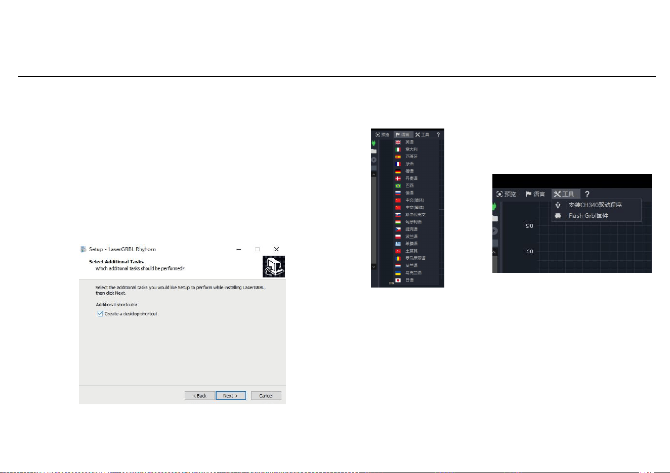
2.Software Installation
Double-click the installer and click "Next" until
installation is complete
3.Language
Click "Language" at the
top menu to select your
preferred language.
4.CH340 Driver Installation
Method 1: Click "Tools" in the
menu to install the CH340 driver
(not available in some versions).
Method 2: Copy the "CH340SER" file
from the TF card to your computer
and install it.
5. Power-on Self-Test
5.1 Connect the power cord to the DC port on
the motherboard.
5.2 Press the power button to turn on the
machine. Press the button three times shortly,
and the machine will run a test program
(return to origin and traverse the maximum
engraving area twice).
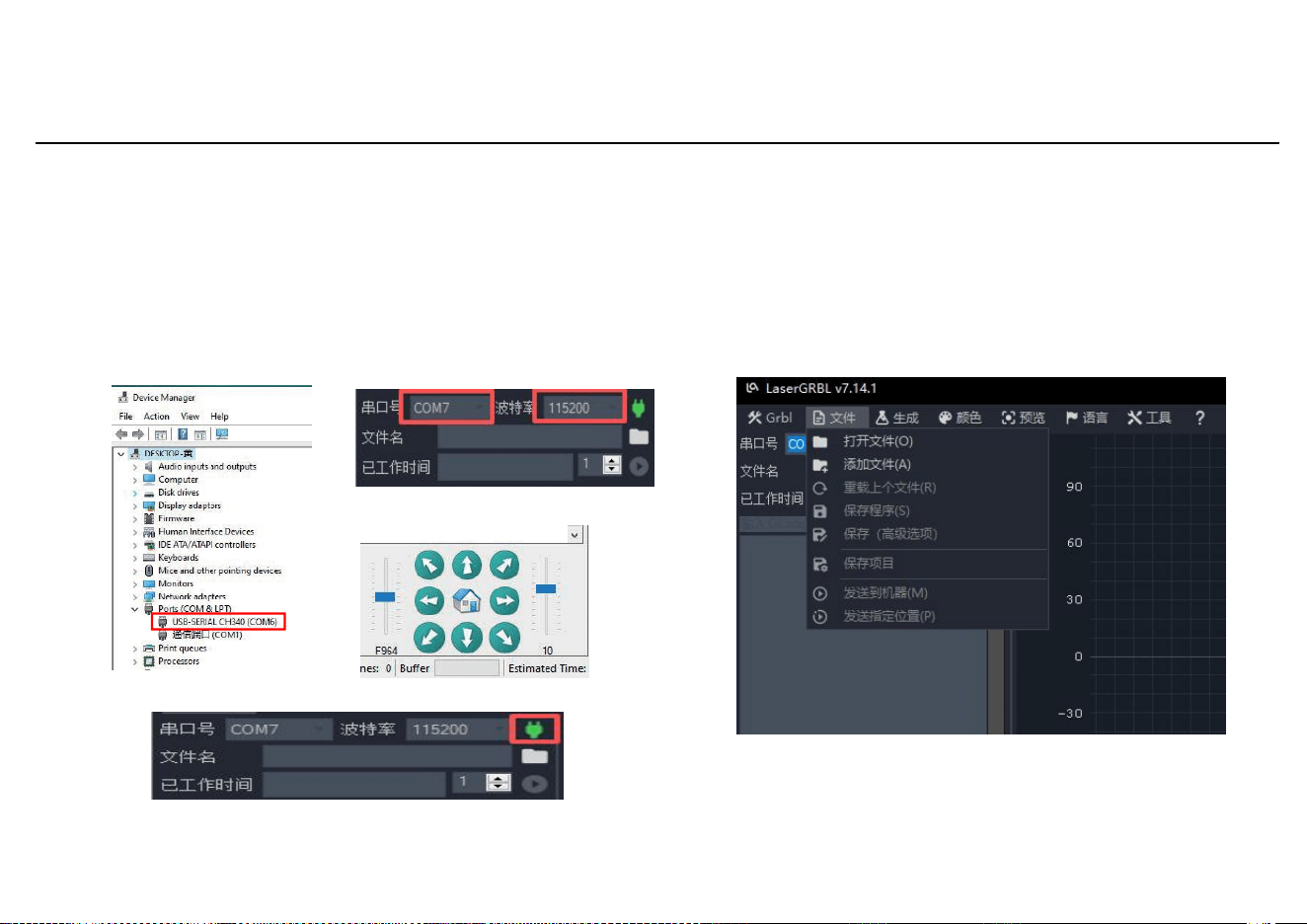
6. Computer Connection
1. Connect the machine to the computer via the data cable.
2.Open LaserGRBL on the computer.
3.Select the specific port number and baud rate 115200 (Figure A).
4.Click the green plug icon (Figure B). When the direction icon
lights up, the connection is successful (Figure C). Normally,
manual port selection is not needed unless multiple serial
devices are connected. Check the port in Windows Device Manager
(Figure D). Alternatively, try each port number.
图D
图A
图C
图B
Machine Testing
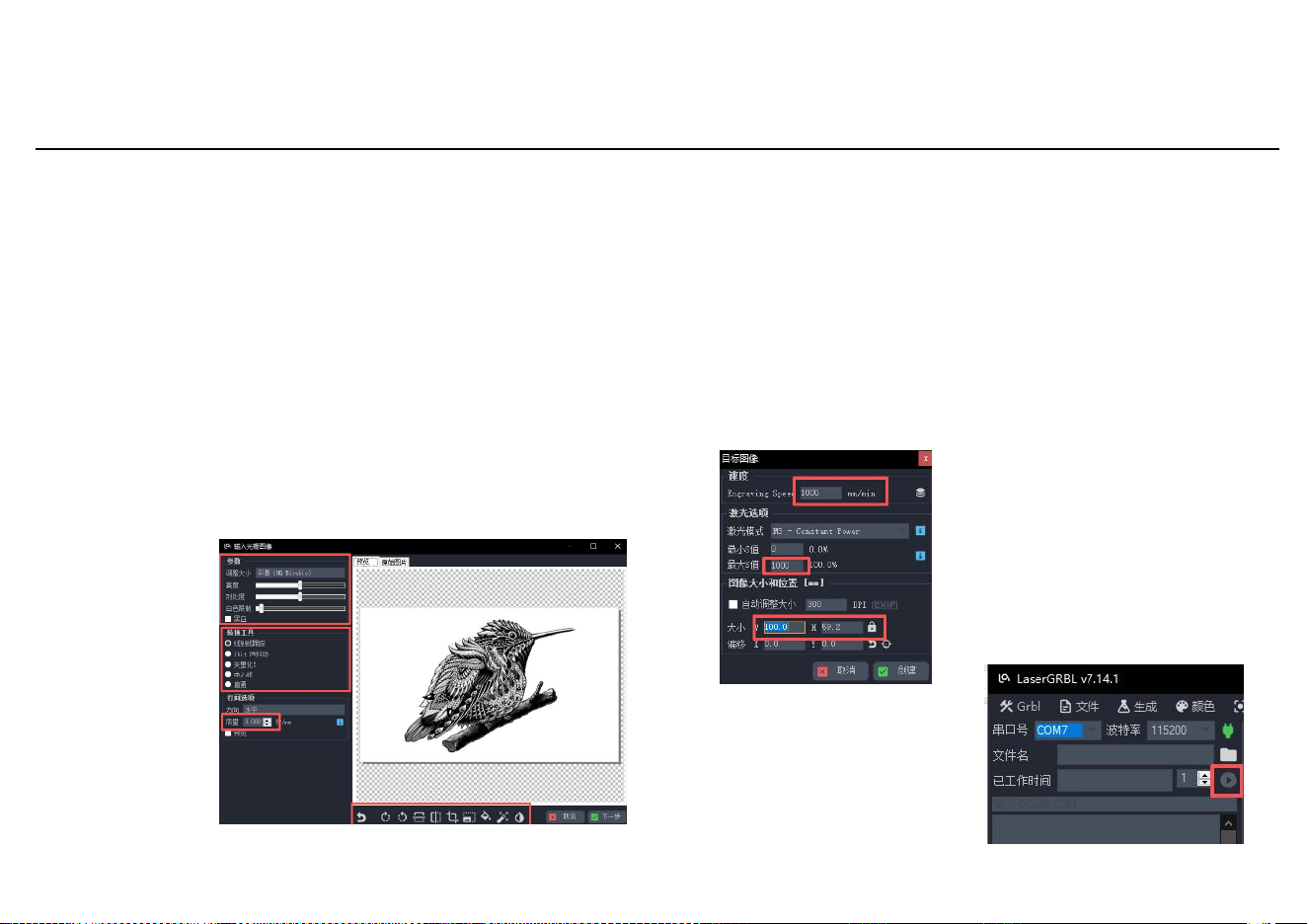
Click "File" and "Open File,"
then select the graphic to
engrave. LaserGRBL supports
NC, BMP, JPG, PNG, etc.
7.Load Engraving File
Machine Testing
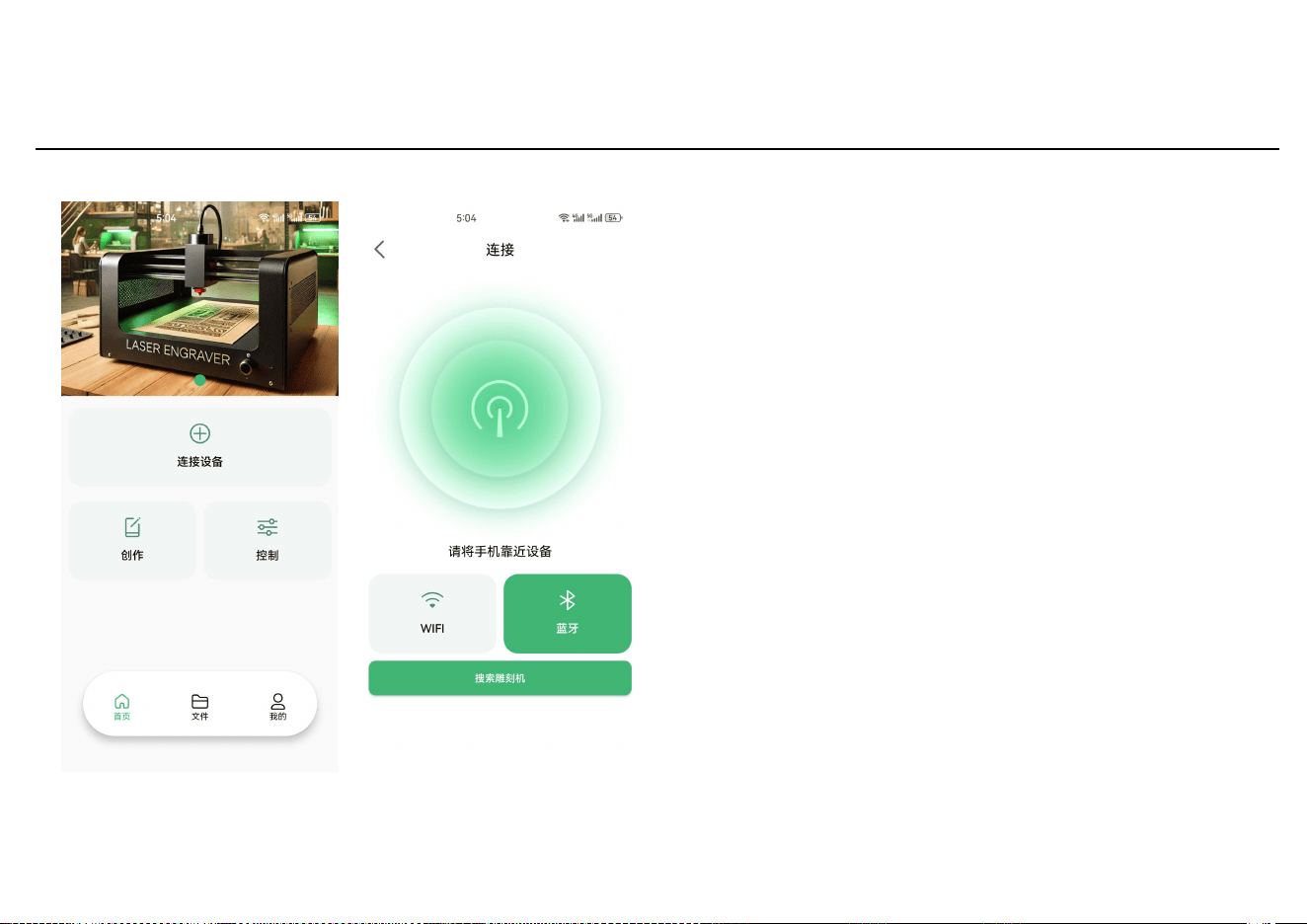
8. Set Image Parameters, Engraving Mode, and Quality。
1. Adjust sharpness, brightness, contrast,
highlights, etc., in LaserGRBL. Preview the effect
and adjust to satisfaction.
2.For engraving mode, typically choose "Line To Line
Tracing" or "1bit Bw Dithering" (better for
grayscale images). For cutting, select "Vectorize!"
or "Centerline."
3.Engraving line width depends on the laser spot
size. Recommended quality range: 12-15. Adjust based
on material response.
4.Rotate, mirror, or cut the graphic in the preview
window. After settings, click Next to set speed,
energy, and size.
Color adjustment; Intensity adjustment
Direction adjustment; Pattern cutting
Color
adjustment;
intensity
adjustment
Select
carving mode
Quality:
12-15
(recommen
ded)
Direction adjustment; pattern
cutting
9.Set Engraving Speed, Energy, and Size
1. The recommended engraving speed is 8000, which has been
found to be relatively suitable after repeated experiments. Of
course, you can adjust this speed according to your preference.
A higher engraving speed will save time but may reduce the
engraving quality.
2. In laser mode, there are two commands: M3 and M4. If your
laser only has the M3 command, please check whether this laser
mode is used in the GRBL configuration. For GRBL configuration,
refer to the official LaserGRBL instructions.
3. Choose the engraving power according to different materials.
4. Finally, set the dimensions and click the "Create" button to
complete all engraving parameter settings.
10. Start carving
After returning to the
main interface, click the
start button as shown to
begin carving
The default carving speed is
1000 and can be adjusted as
needed.
Set the energy level; too much
energy can affect the
engraving result.
Enter the dimensions of the
design to be carved
App Introduction
APP Connection
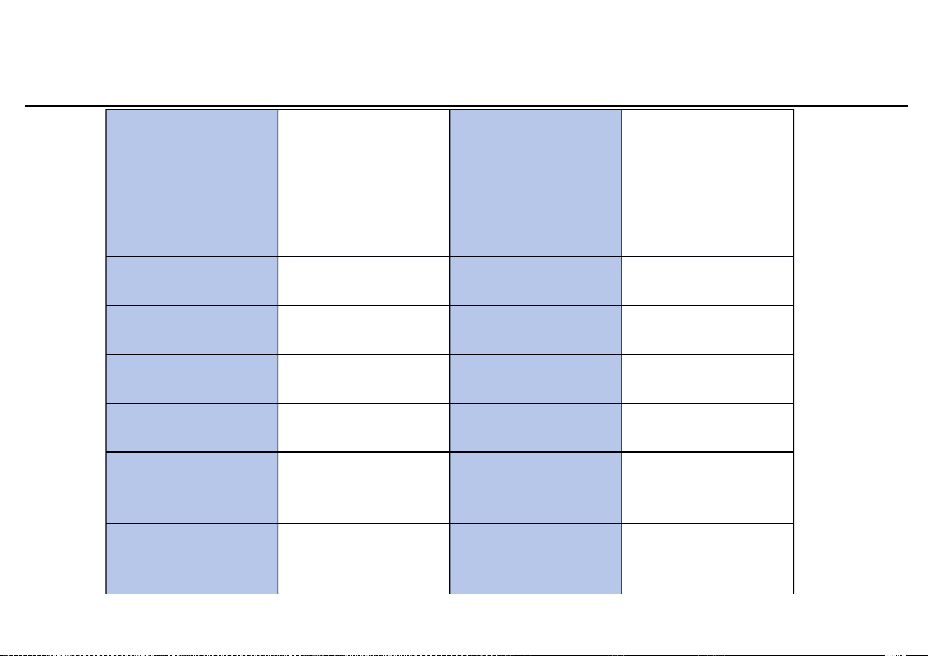
Open the mobile app, click on
'Connect Device', then click
'Bluetooth' and 'Search for Engraver'.
The mainboard will send a Bluetooth
name called Laser-XXXXX (XXXXX
refers to the mainboard's serial
number, which is different for each
machine).
Note: After completing the slicing in
the app, you need to insert the TF
card into the mainboard when
uploading files. If the upload fails,
please check if the TF card is
functioning properly.

Regular maintenance
1. Laser Head and Lens Cleaning
Check whether there is dust or smoke residue on the laser lens surface (smoke and dust generated
during laser processing easily adhere to the lens, causing laser energy loss and reduced processing
accuracy). Cleaning method: use a cotton swab dipped in a small amount of alcohol to gently wipe the
lens surface in one direction. Do not rub back and forth or touch with hard objects. After cleaning,
make sure the alcohol has completely evaporated before powering on.
2. Transmission Component Check
Check the tension of the belt. If the belt is loose, it may cause processing accuracy deviations. The belt
can be tightened by loosening the screw that holds it, pulling the belt tight, and then re-tightening the
screw. Clean the dust on the belt surface to prevent slipping.
3. Limit Switch Check
Manually trigger the limit switch on each axis and confirm that the device can stop normally to avoid
over-travel that could damage components. Clean dust from the surface of the limit switch to prevent
poor contact.
4. Worktable Cleaning
Remove processing debris and waste material from the table to prevent scratches on the worktable or
affect the positioning accuracy of the next process.
5.Equipment Appeara nce and Power Supply Check
Wipe the dust off the equipment casing and check whether the power cord,
data cables, and air hoses are loose or worn to prevent short circuits or signal
interruption.
Product Specifications
Name
Laser Engraving
Machine
Net Product Weight
2.5KG
Model
L1 pro
Packaging Weight
3.5KG
Molding Technology
Laser Engraving
Internal Packaging
Dimensions
510x166x240mm
Main Body Color
Black + Blue
External Packaging
Dimensions
525*186*260mm
Main Body Material
Aluminum + Injection
Molded Parts
Transmission Timing
Belt Model
GT2-6mm
Product Dimensions
483*487*184mm
X/Y - axis Positioning
Accuracy
0.01mm
Working Range
300x300mm
Engraving Accuracy
±0.1mm
Engraving Materials
Wooden boards, plastics,
paper, leather, bamboo,
sponge paper, stainless
steel, Celuka board, acrylic
Maximum Engraving
Speed
12000mm/min
Operating Frequency
2.4GHz
RF Output Power
10dBm

Caution: The user is cautioned that changes or modifications not expressly approved by the party responsible for
compliance could void the user's authority to operate the equipment.
This device complies with Part 15 of the FCC Rules. Operation is subject to the following two conditions: (1) this device
may not cause harmful interference, and (2) this device must accept any interference received, including interference
that may cause undesired operation.
NOTE: This equipment has been tested and found to comply with the limits for a Class B digital device, pursuant to Part
15 of the FCC Rules. These limits are designed to provide reasonable protection against harmful interference in a
residential installation. This equipment generates, uses and can radiate radio frequency energy and, if not installed and
used in accordance with the instructions, may cause harmful interference to radio communications. However, there is
no guarantee that interference will not occur in a particular installation. If this equipment does cause harmful
interference to radio or television reception, which can be determined by turning the equipment off and on, the user is
encouraged to try to correct the interference by one or more of the following measures:
-- Reorient or relocate the receiving antenna.
-- Increase the separation between the equipment and receiver.
-- Connect the equipment into an outlet on a circuit different from that to which the receiver is connected.
-- Consult the dealer or an experienced radio/TV technician for help.
FCC Radiation Exposure Statement:
This equipment complies with FCC radiation exposure limits set forth for an uncontrolled environment. This transmitter
must not be co-located or operating in conjunction with any other antenna or transmitter.
This equipment should be installed and operated with a minimum distance of 20cm between the radiator and your
body.
Warning

TEL:+0086-0755-23987110
Official Website: https://laservii.com/
E-mail: [email protected]
Wiki:https://wiki.laservii.com/en/home
Facebook: https://www.facebook.com/profile.php?id=61584424918207
Manufacturer:Laservii (Shenzhen) Technology Co.,Ltd.
Address: 201,Nankeng Second industrial Zone, Nankeng Community, Bantian
Street, Longgang District.Shenzhen, China, 518000
6022601