
Installation and Operation Manual
PL5 Series
Handheld Fiber Laser Marking System

PL5 Series Fiber Laser Marking System Page 2 of 40
CONTENTS
1 INTRODUCTION ......................................................................................................................................................4
1.1 Product Overview ....................................................................................................................................... 4
1.2 Manufacturer and Customer Service ..........................................................................................................4
2 SAFETY ....................................................................................................................................................................5
2.1 Signal Words and Symbols in this Manual .................................................................................................. 5
2.2 Classification of Laser Systems ....................................................................................................................5
2.3 Hazards ........................................................................................................................................................6
2.3.1 Laser Hazards .............................................................................................................................................................6
2.3.2 Electrical Safety ..........................................................................................................................................................6
2.3.3 Other Hazards ............................................................................................................................................................7
2.4 Compliance ................................................................................................................................................. 7
2.4.1 RoHS Compliance .......................................................................................................................................................7
2.4.2 FCC Requirements ..................................................................................................................................................... 7
3 PRODUCT DESCRIPTION .........................................................................................................................................8
3.1 General Description .................................................................................................................................... 8
3.1.1 Laser Marking Head ...................................................................................................................................................8
3.1.2 Controller and WINCE System ................................................................................................................................... 8
3.2 Product Labeling ......................................................................................................................................... 9
3.3 Technical Information................................................................................................................................. 9
3.3.1 General Specifications ............................................................................................................................................... 9
3.3.2 Mechanical Layout and Dimensions .......................................................................................................................11
4 INSTALLATION ...................................................................................................................................................... 12
4.1 Unpacking and Inspection .........................................................................................................................12
4.2 Shipping Contents..................................................................................................................................... 12
4.3 Transport, Handling and Storage .............................................................................................................. 12
4.3.1 Transport .................................................................................................................................................................12
4.3.2 Handling ..................................................................................................................................................................12
4.3.3 Storage....................................................................................................................................................................13

PL5 Series Fiber Laser Marking System Page 3 of 40
4.4 Air Cooling .................................................................................................................................................13
5 START-UP AND OPERATION..................................................................................................................................14
5.1 Checking the Installation ...........................................................................................................................14
5.2 Safe Start-up and Shutdown Sequences ...................................................................................................14
5.3 Operation of WINCE System ..................................................................................................................... 14
5.3.1 Home Screen and Description .................................................................................................................................14
5.3.2 Keys and Functions .................................................................................................................................................. 16
5.3.3 Marking ...................................................................................................................................................................29
5.3.4 Lens Correction .......................................................................................................................................................30
5.3.5 Setting .....................................................................................................................................................................33
6 MAINTENANCE .....................................................................................................................................................38
6.1 General Notes ........................................................................................................................................... 38
6.2 Maintence Procedures ..............................................................................................................................38
6.2.1 General Maintence Procesures .............................................................................................................................. 38
6.2.2 Clean the Lens .........................................................................................................................................................38
7 TROUBLESHOOTING .............................................................................................................................................40

PL5 Series Fiber Laser Marking System Page 4 of 40
1 INTRODUCTION
The manual is a part of the product. Please read these instructions carefully before you install and
operate the PL5 Series Handheld Fiber Laser Marking System. If there are any questions regarding the
contents of this manual, please contact us.
The manual must be available for developing, installing, uninstalling or using a laser system with a Phezer
product.
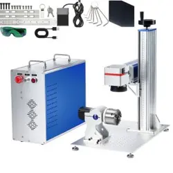
1.1 Product Overview
The Phezer PL5 Series Handheld Fiber Laser Marking Systems are produced by Wuhan Phezer Technology
Co., Ltd. (herein refer to as Wuhan Phezer or Phezer Laser).
The Phezer PL5 Series Handheld Fiber Laser Marking Systems have been developed and designed for
fully automated marking on packaging materials and products by using laser radiation.
The laser marking system must only be operated by authorized and specifically trained personnel who
are familiar with and observe the procedures within this manual.
1.2 Manufacturer and Customer Service
WUHAN PHEZER TECHNOLOGY CO., LTD.
Zhongnan International City, Zhongnan Road, Wuchang District, Wuhan, Hubei, China
www. phezer.com
PL5 Series Fiber Laser Marking System Page 5 of 40
2 SAFETY
This section must be reviewed thoroughly before operating the PL5 Series Handheld Fiber Laser Marking
Systems. Safety instructions in this manual must be followed carefully.
2.1 Signal Words and Symbols in this Manual
In this manual the following safety symbols have been used to alert the users to the text of the safety
instruction next to it.
WARNING
CAUTION
DANGER
This symbol is intended to alerts the operator of serious dangers, hazardous
radiation, vapor hazard, & reflective dangers. Potential & Imminent hazards
which, if not avoided, could result in death or serious injury.
WARNING
DANGER
This symbol is intended to alert the operator to the danger of exposure to
hazardous visible and invisible laser radiation.
WARNING
This symbol is intended to alert the operator to the presence of dangerous
voltages within the product enclosure that may be of sufficient magnitude to
constitute a risk of electric shock.
2.2 Classification of Laser Systems
Every laser system is assigned to a laser class, which must be specified at the output location of the laser
beam.
DANGER
The Phezer PL5 Series fiber lasers is class IV products which are dangerous
to the eyes and skin. Avoid eye or skin exposure to the laser radiation.
Class
Description
1
The accessible laser radiation is not dangerous, is eye-safe.
1M
Exposure to this radiation is harmful to the eyes if optical instruments are used to reduce
the cross section of the laser beam. If this is not the case, this laser radiation is not harmful,
is eye-safe.
2
The laser radiation is in the visible spectral range of 400 nm to 700 nm. Short exposure time
less than 0.25s are not dangerous to the eyes.
2M
The laser radiation is in the visible spectral range of 400 nm to 700 nm.
Exposure to this radiation is harmful to the eyes if optical instruments are used to reduce
the cross section of the laser beam. If this is not the case, exposure to this radiation for less
than 0.25s is not harmful to the eyes and is eye-safe

PL5 Series Fiber Laser Marking System Page 6 of 40
3R
The laser radiation is in the wavelength range of 302.5nm to 10nm and is dangerous to the
eyes.
3B
The laser radiation is dangerous to the eyes and in some case also to the skin.
4
The laser radiation is very dangerous to the eyes and dangerous to the skin. Stray radiation
can also be dangerous. The laser radiation can cause fire and explosion.
2.3 Hazards
2.3.1 Laser Hazards
Phezer PL5 Series Handheld Fiber Laser Marking Systems should be installed and operated by trained
personnel only who have been instructed by the laser protection officer and are sufficiently qualified to
perform the laser work. Due to the risks and hazards associated with the installation and operation of
the laser, the operator must follow product warning labels and instructions to ensure laser safety.
Always wear safety glasses or protective goggles with side shields to reduce the risk of damage
to the eyes when operating the laser.
A fiber laser is an intense energy source and will ignite most materials under the proper
conditions. Never operate the laser near the combustible or explosive materials, gases, liquids
or vapors.
Exposure to direct or diffuse fiber laser radiation can seriously burn human or animal tissue,
which may cause permanent damage. Do not place your body or any combustible object in the
path of the laser beam.
Appropriate protection mechanisms must be used to avoid laser radiation outside the expected
working area.
2.3.2 Electrical Safety
WARNING
To avoid potentially fatal electrical shock hazards from electrical equipment,
the rules for electrical safety must be strictly followed. Failure to do so could
result in the exposure to lethal levels of electricity.
The Phezer PL5 Series Handheld Fiber Laser Marking Systems use AC voltages. The maximum operating
voltage is the connected mains voltage, which to be maintained is shown on the name plate.
All works at the open laser housing, especially at electrical components, must only be performed by
specially trained personnel!
In the case of a defective power supply, operation of the laser marking system is to be stopped
immediately and is only to be repaired by authorized personnel.

PL5 Series Fiber Laser Marking System Page 7 of 40
2.3.3 Other Hazards
The following hazards are typical for this product family when incorporated for intended use:
Risk of injury when lifting or moving the unit
Risk of exposure to hazardous laser energy through unauthorized removal of access panels,
doors, or protective barriers
Risk of exposure to hazardous laser energy and injury due to failure of personnel to use proper
eye protection and/or failure to adhere to applicable laser safety procedures
Risk of exposure to hazardous or lethal voltages through unauthorized removal of covers, doors,
or access panels
Generation of hazardous air contaminants that may be noxious, toxic, or even fatal during laser
processing.
2.4 Compliance
Phezer PL5 Series Handheld Fiber Laser Marking Systems are designed, tested, and certified to comply
with certain China (CN), United States (U.S.) and European Union (EU) regulations. These regulations
impose product performance requirements related to electromagnetic compatibility (EMC) and product
safety characteristics for industrial equipment.
2.4.1 RoHS Compliance
Phezer PL5 Series Handheld Fiber Laser Marking Systems meet the requirements of the European RoHS
Directive 2011/65/EU on the Restriction of the Use of Certain Hazardous Substances in Electrical and
Electronic Equipment that establishes maximum concentration values for certain hazardous substances
in electrical and electronic equipment.
2.4.2 FCC Requirements
Phezer PL5 Series Handheld Fiber Laser Marking Systems are designed to meets the FCC Rules. The
purpose of the design is to prevent harmful electromagnetic interference.
The FCC warns the user that changes or modifications of the unit not expressly approved by the party
responsible for compliance could void the user’s authority to operate the equipment.
PL5 Series Fiber Laser Marking System Page 8 of 40
3 PRODUCT DESCRIPTION
3.1 General Description
Phezer PL5 Series Handheld Fiber Laser Marking System is high performance laser marking system which
developed and produced by the Phezer professional team based on the years experience of laser
development, production and service.
The laser marking machine contains two parts: laser marking head and controller.
The controller is a highly integrated industrial computer system, mainly used in marking information
input, edit and fast and precise control of the laser and galvanometers.
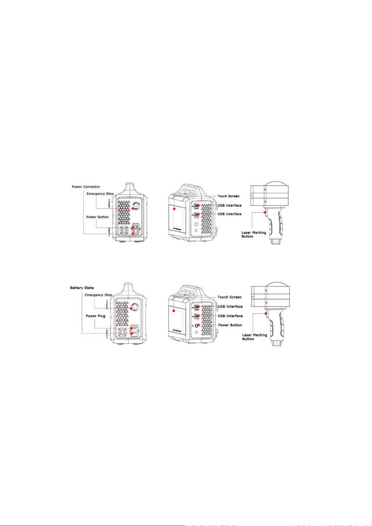
Description: Power version of PL5 Series Handheld Fiber Laser Marking Systems
Description: Battery version of PL5 Series Handheld Fiber Laser Marking Systems
3.1.1 Laser Marking Head
The laser marking head is connected to the controller and cannot be removed. The laser marking head
contains the glavo scan head and f-theta lens. The beam is deflected by the 2-dimension galvanometers
and focused by the f-theta lens to the working surface with appropriate focal length.
3.1.2 Controller and WINCE System
The Phezer controller is a highly integration of laser source and industrial control computer, containing
fiber laser source, built-in marking control system, 7-inch LCD touch screen, which allows an external
keyboard, mouse, monitor, and USB devices.

PL5 Series Fiber Laser Marking System Page 9 of 40
WARNING
Do not to use the sharp hard object to operate the touch screen. This may
damage the screen and affect the touch sensitivity, also may void the
warranty due to such improper use.
3.2 Product Labeling
3.3 Technical Information
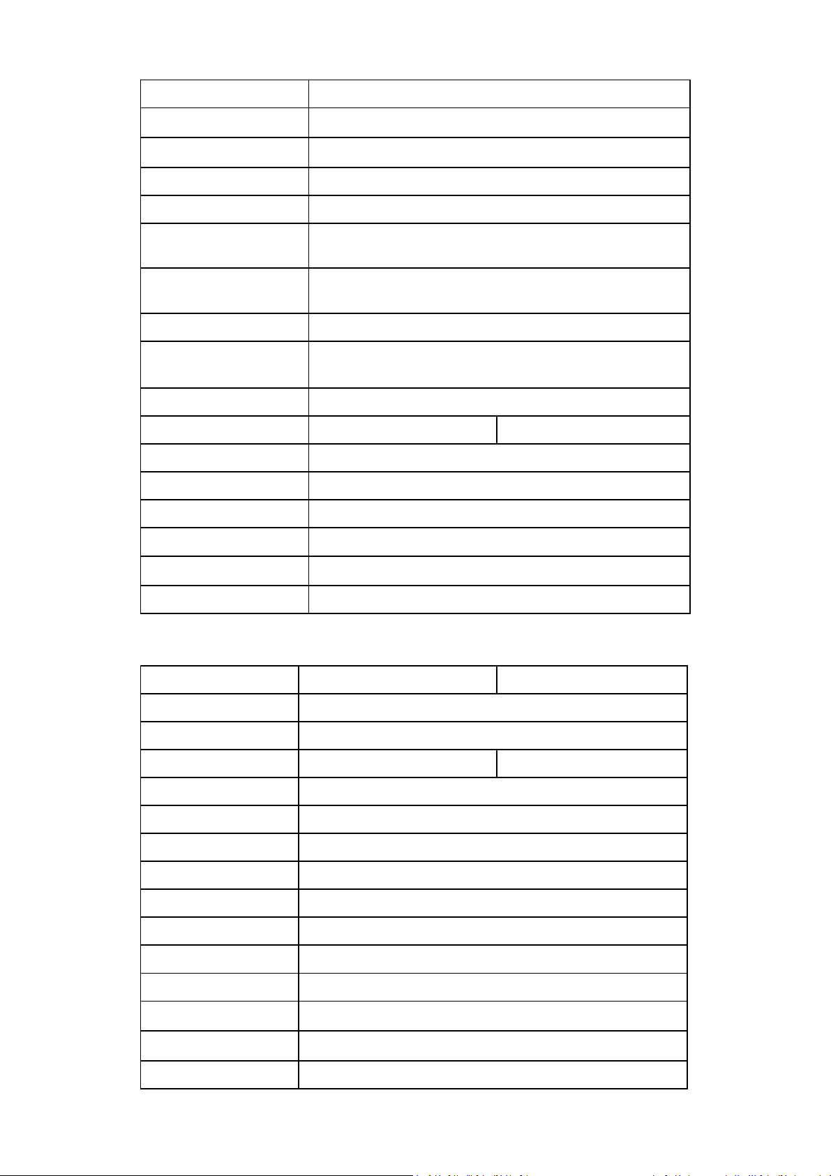
3.3.1 General Specifications
Original (non-battery) Version 20W / 30W
Specification
PL5-20W
PL5-30W
Case material
Engineering plastic
Laser type
Fiber laser source
Output power
≥20W
≥30W
Laser wavelength
1064nm
Maximum pulse energy
0.8mJ
Frequency range
1-600 kHz
Marking method
High-precision two-dimensional scanning method
Line speed
≤7000mm/s
Control system
Highly- integrated motherboard, built-in 7-inch touch screen
Operating system
Linux
Cooling system
Air cooled
PL5 Series Fiber Laser Marking System Page 10 of 40
Type of marking line
Dot matrix and vector
Reflector size
Standard size
:
8.5mm
Marking range
Standard
:
50mm×50mm or 100mmx100mm
Positioning method
Red light positioning
Lines of marking
Any number of lines within the marking range
Marking speed
650 characters/sec (the specific speed is related to product
material and printing contents)
Fonts
Simplified Chinese, Traditional Chinese, English, Korean, Russian,
Arabic numerals and other standard font libraries
File format
BMP/DXF/HPGL/JPEG/PLT
Bar code / QR code
CODE39、CODE128、CODE126、QR、Z-code、DM, visual
code, etc.
Power
220V
Max power
≤200W
≤250W
N.W
9kg
Control box
310mmX206mmX307mm
Pollution level
2
Over-voltage category
Ⅱ
Working temperature
0-40℃
Working humidity
30%-95%RH (no condensing)
Battery Version 20W / 30W
Specification
PL5-20W
PL5-30W
Case material
Anodized aluminum structure
Laser type
Fiber laser source
Output power
≥20W
≥30W
Laser wavelength
1064nm
Frequency range
1-600 kHz
Marking method
High-precision two-dimensional scanning method
Line speed
≤7000mm/s
Control system
Highly- integrated motherboard, built-in 7-inch touch screen
Operating system
Linux
Cooling system
Air cooled
Type of marking line
Dot matrix and vector
Reflector size
Standard size
:
8.5mm
Marking range
Standard:50mm×50mm or 100mmx100mm
Positioning method
Red light positioning
PL5 Series Fiber Laser Marking System Page 11 of 40
Lines of marking
Any number of lines within the marking range
Marking speed
650 characters/sec (the specific speed is related to product
material and printing contents)
Fonts
Simplified Chinese, Traditional Chinese, English, Korean, Russian,
Arabic numerals and other standard font libraries
File format
BMP/DXF/HPGL/JPEG/PLT
Bar code / QR code
CODE39、CODE128、CODE126、QR、Z-code、DM, visual code,
etc.
Battery capacity
12Ah
Working hour
≤5.5H
N.W
9.8kg
Control box
310mmX206mmX307mm
Pollution level
2
Over-voltage category
Ⅱ
Working temperature
0-40
℃
Working humidity
30%-95%RH (no condensing)
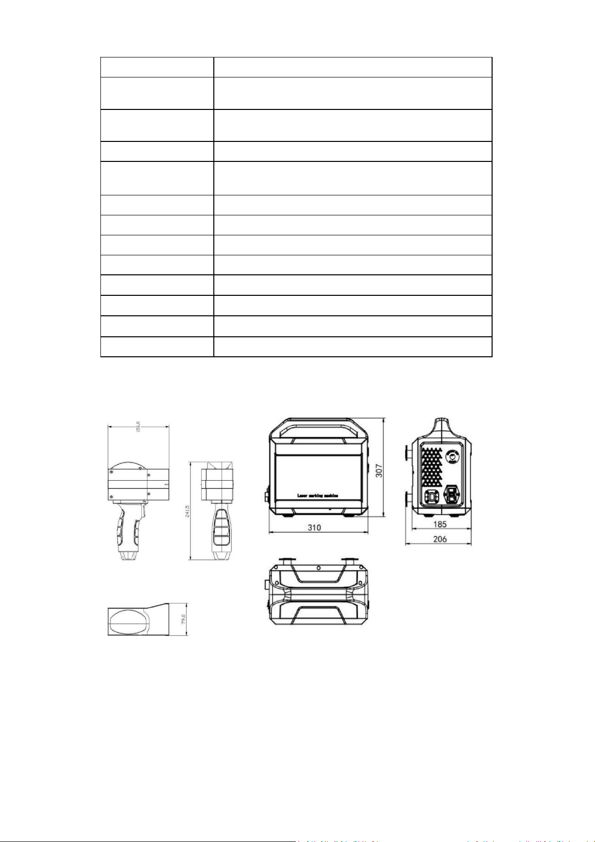
3.3.2 Mechanical Layout and Dimensions
Dimensions: PL5 Series Handheld Fiber Laser Marking Systems

PL5 Series Fiber Laser Marking System Page 12 of 40
4 INSTALLATION
4.1 Unpacking and Inspection
Before unpacking, inspect the shipping carton for evidence of rough handling, and note any damage. If
you discover shipping damage to the laser, document the damage with a photograph, then immediately
inform the shipping carrier and Phezer.
After unpacking, review the shipping contents listed below to ensure all components are received.
Saving all of the laser’s original packaging in case of relocation or shipping .
Protect the laser system and all components from dust and humidity until installation.
CAUTION
The laser marking system must only be installed and operated by authorised
and specifically trained personnel only.
The installation of the laser marking system has to comply to IEC 60825-1.
4.2 Shipping Contents
Each PL5 Series fiber laser marking system shipment contains the following items:
1 ea x Laser Marking Head
1 ea x Control Box
1 ea x Took Kits and Bolts
1 ea x Network Card
1 ea x Screen Protective Cover
1 ea x U disk
1 ea x Touch Pencil
2 ea x White Plastic Cover
1 ea x Protective Glasses
4.3 Transport, Handling and Storage
4.3.1 Transport
Switch off the laser system before transport and disconnect mains connection!
Please make sure that the supply line connecting marking unit and supply unit is not bent!
Do not use the umbilical to carry the laser system!
CAUTION
The laser system is a precision-made instrument and includes numerous
electronic and optical components. Please avoid any mechanical stress
(shock, vibrations, etc.) on the laser system!
4.3.2 Handling

PL5 Series Fiber Laser Marking System Page 13 of 40
The equipment must be handling appropriately and carefully.
The laser head must not be held by the scanner head or by the supply lines.
The control unit is to be specifically protected during assemlbly.
4.3.3 Storage
Store the laser system in a horizontal position and protected against dust and humidity.
Never expose the laser system or one of its components to direct sunlight!
The following conditions are necessary for operation and storage of the laser marking system:
Temperature +5°C to +40°C
90% max relative humidity - non-condensing
4.4 Air Cooling
Phezer PL5 Series Handheld Fiber Laser Marking Systems are cooled by air. The internal cooling system is
designed to supply sufficient cooling.
Make sure that the cooling air can be sucked in and blown out freely and that there is sufficient air
exchange at the installation site to ensure heat dissipation.
CAUTION
Keep the air inlet and outlet clean, otherwise it will affect the working
efficiency of the laser.
PL5 Series Fiber Laser Marking System Page 14 of 40
5 START-UP AND OPERATION
5.1 Checking the Installation
Before start-up and operation of the laser marking system, carefully check the following:
Check whether the specifications are correct.
Check whether all mechanical installations are complete and correct.
Check whether all electrical connections are complete and correct.
Check whether all optical components are clean and free of dust.
5.2 Safe Start-up and Shutdown Sequences
To assure safety during start-up, proceed exactly as follows:
1. Ensure that all personnel in the area are wearing protective eyeglasses.
2. Remove protective cover on the beam exit hole.
3. Connect the AC power(For non-battery version only).
4. Turn on the Emergency Switch.
5. Press the Power Button
6. Wait 3 minutes to enter the system and software interface.
When shutdown, please turn off the system exactly in reserve order.
5.3 Operation of WINCE System
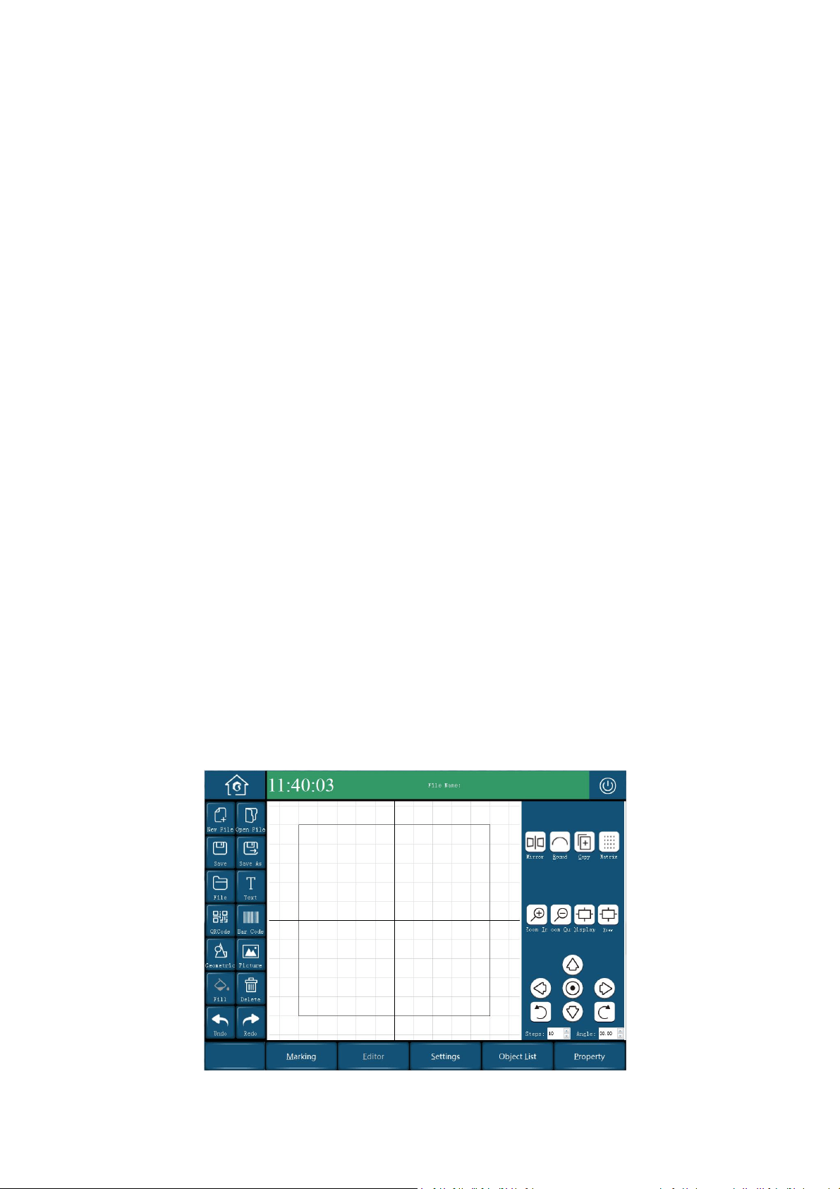
5.3.1 Home Screen and Description
PL5 Series Fiber Laser Marking System Page 15 of 40
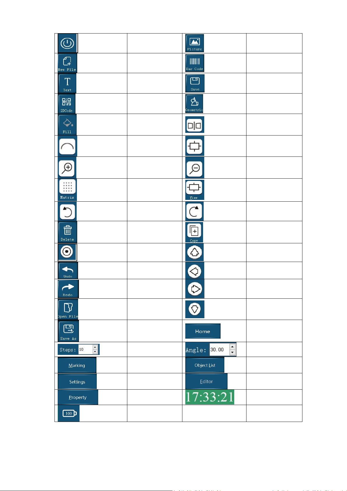
Turn off
Add New Picture
Add New File
Barcode
Add Text
Save
2D Code/QR Code
Geometric
Filling
Mirror
Text Arc Layout
Display Objet
Zoom Out
Zoom In
Array Setting
View
Rotate 30° to the
left
Rotate 30° to the
right
Delete
Copy
Object Centered
Object Up
Objet Undo
Object Left
Objet Redo
Object Right
Open File
Object Down
Save As File
Return Home Screen
Distance moved
once
Angle of rotation
once
Marking
Object List
Settings
Edit Object
Property
Real Time
Battery power
PL5 Series Fiber Laser Marking System Page 16 of 40
5.3.2 Keys and Functions
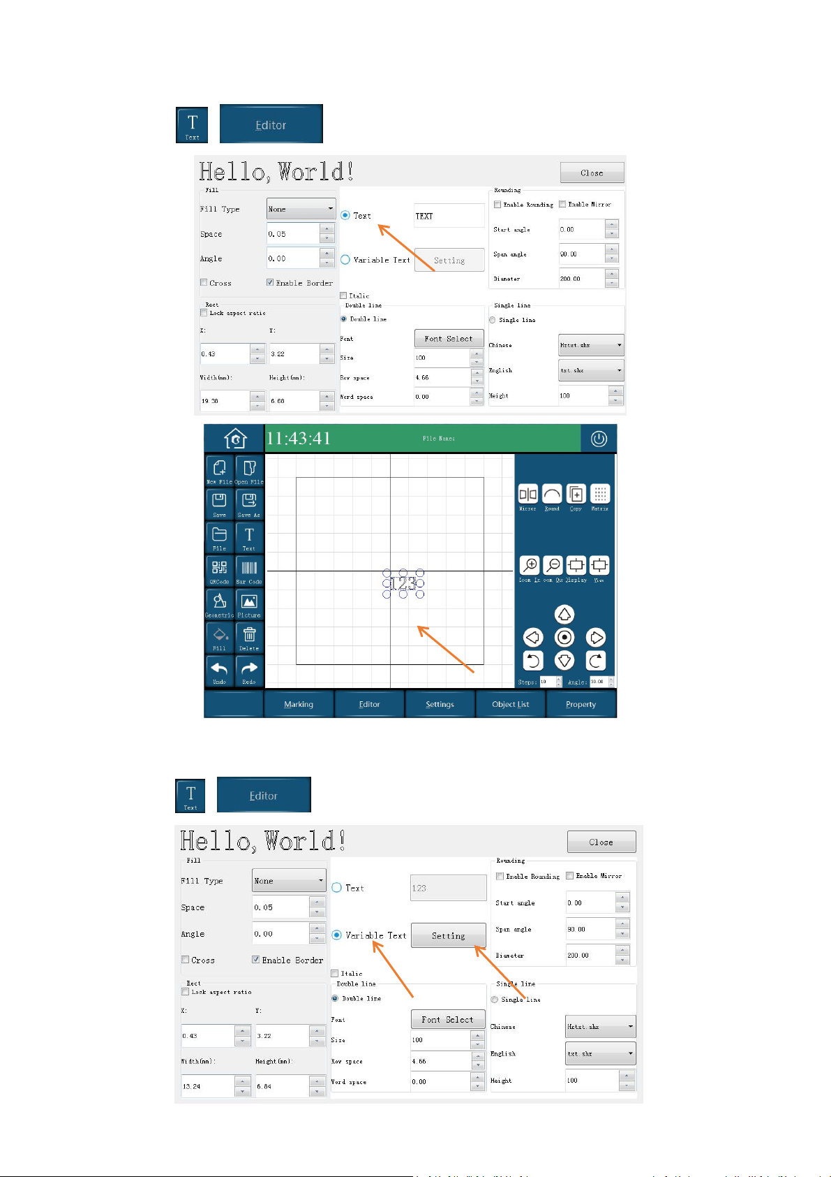
1. Creating A New Text
Add New File →Text , press the screen within specific area, and then, select at
the bottom of screen to edit the text, as shown below:
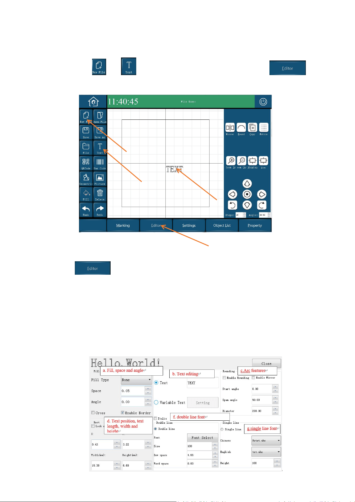
2. Editing A Message
Select to enter the interface show as below, edit the text and select the features for the
text:
Fill, space, angle
Text editing
Arc features
Text position, text length, width and height
Double line font
Single line font
PL5 Series Fiber Laser Marking System Page 17 of 40
3. Add a New Fixed Message
Select → , edit your text, shown as following:
4. Add a New Variable
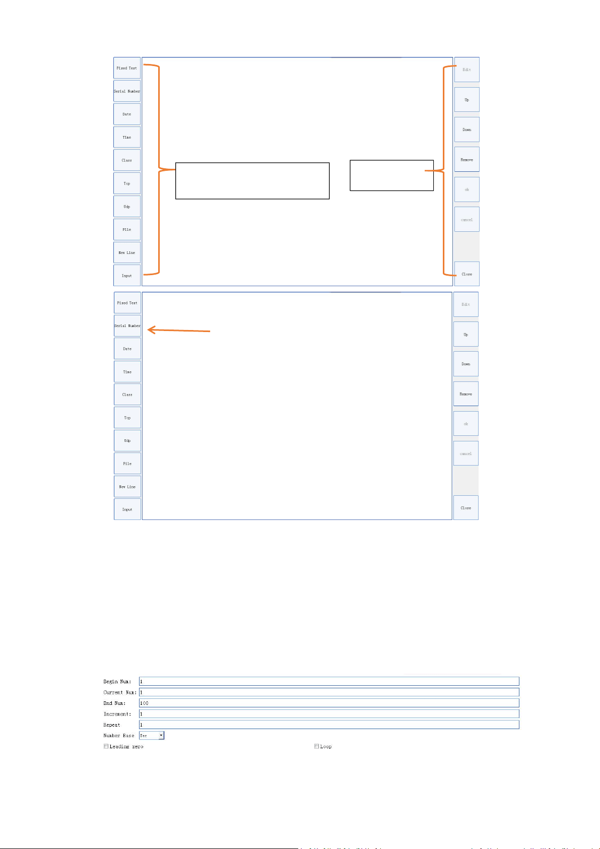
Select → , enable Variable Text and select Setting, shown as below:
PL5 Series Fiber Laser Marking System Page 18 of 40
Set Serial Nmber
Begin Num: set the starting value of the serial number.
End Num: set the maximum value of the serial number (if the end value is 0, there is no limit).
Increment: the increased value.
Repeat: Whether to restart the marking with same starting value of serial number after all serial
number have been marked. Default: Yes).
Base: Set the number base for serial number. Decimal, octal, and hex can be set.
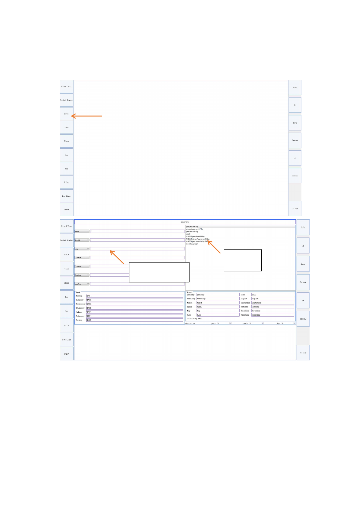
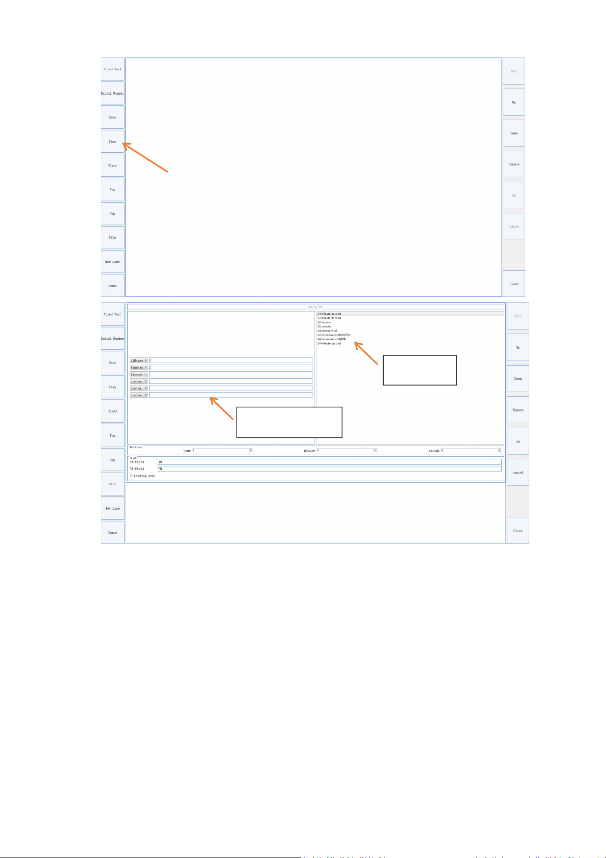
Set Date & Time
Tool bar
Setting bar for variable
PL5 Series Fiber Laser Marking System Page 19 of 40
There are several default formats to choose for setting date and time time. If there is not what
you need, you can modify the format after selecting
,
like adding horizontal lines, text, spaces
and slash, etc., to get your desired date format.
For example, “2020/05/23” can be modified as “15:24:23”
Template
Custom template
PL5 Series Fiber Laser Marking System Page 20 of 40
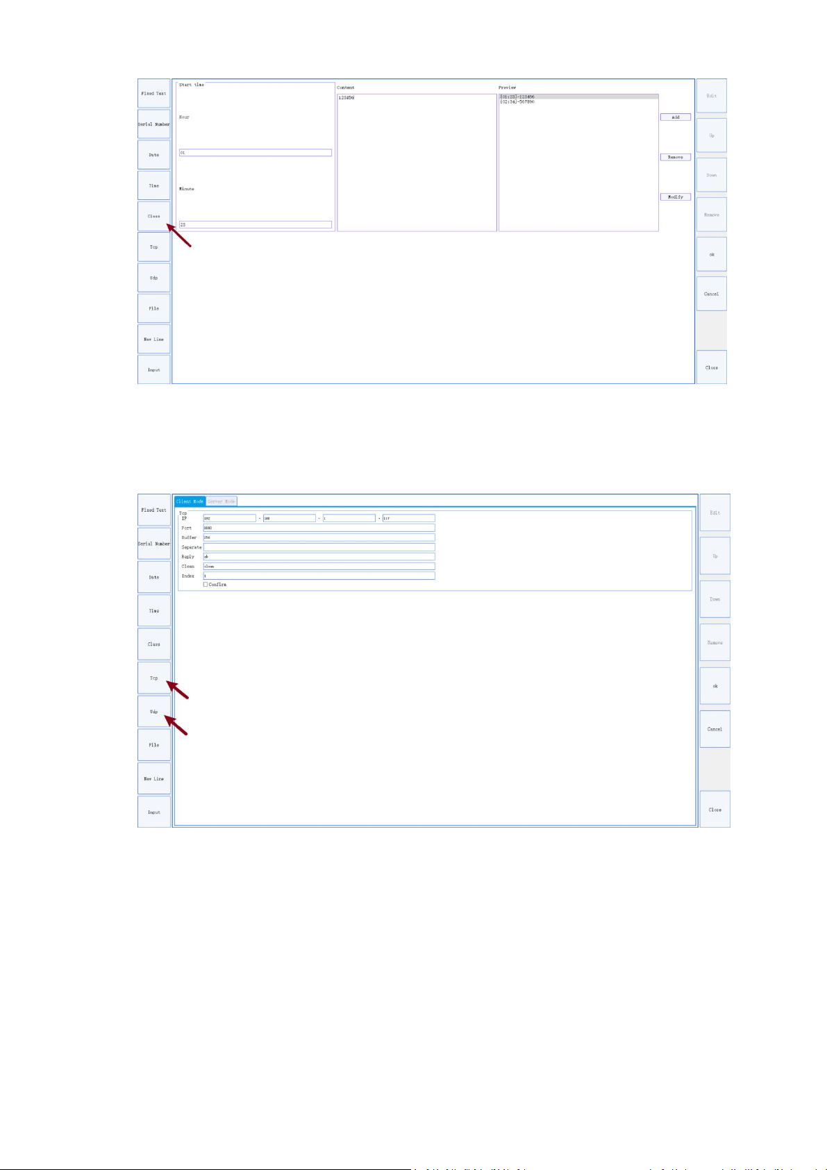
Set Working Shift
Start Time: Set the start time of the shift.
Content: Set the content of the shift
Preview: View the added shift time and content
Add: Add new shift, first set the start time and content, then push the “add” button;
Remove: Remove the selected shift
Modify: Modify the selected shift
Template
Custom Template
PL5 Series Fiber Laser Marking System Page 21 of 40
Set TCP and UDP connect
Client Mode: Actively connect to receive text data from the server
Server Mode: Passive connection, receiving text data sent by the client
Use value in file
File Type: only supports TXT and Excel format files (There can only be one data per line in the
TXT and Excel files)
Current: the current value ready to be mark
IsLoop: Mark the values in the file cyclically

PL5 Series Fiber Laser Marking System Page 22 of 40
Add New Line
Insert ‘newline’ between two texts or variable texts, the effect is shown in the figure below
PL5 Series Fiber Laser Marking System Page 23 of 40
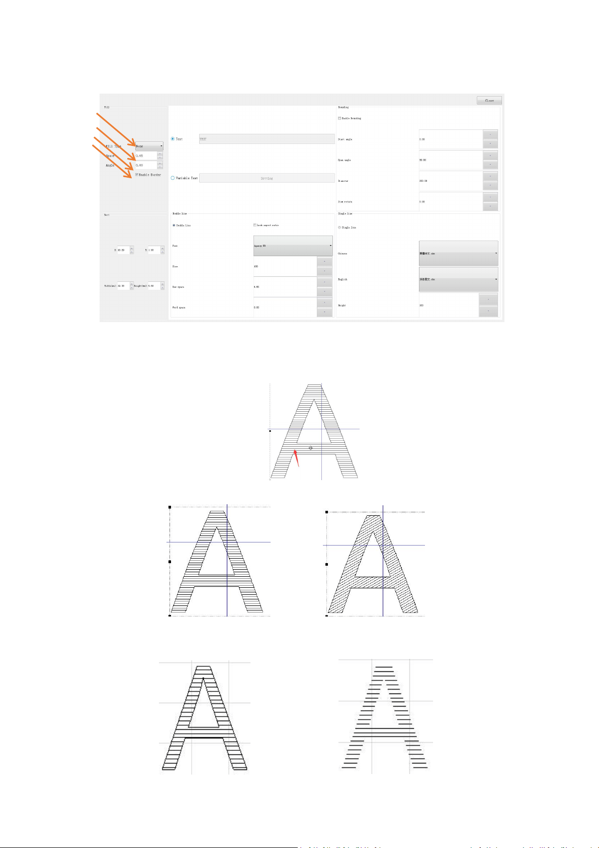
5. Filling
Types of filling
Space: the spacing between filling lines
Angle: the angle of the filling lines
Angle: 0 Angle: 30
Border: the outline
Boarder No Boarder
PL5 Series Fiber Laser Marking System Page 24 of 40
Fill Type: filling lines style
Line Polyline
Cross filling: fill with two perpendicular lines, you can set the space and angle
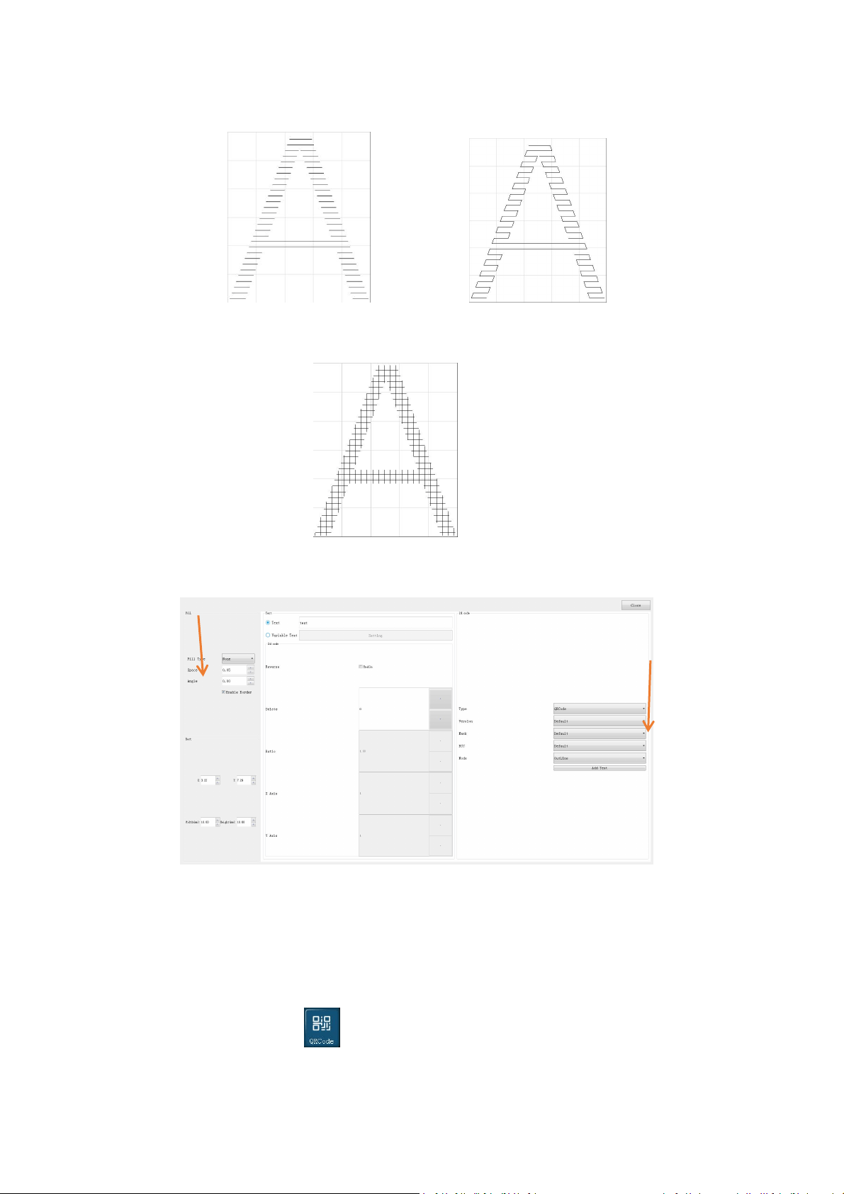
6. Creating A QR Code
Code types
Barcode: 128 Code Auto/A/B/C,39 code,93 code,EAN 13 code,PDF 417 code,01 code.
QR Code: DataMatrix
,
GS1-DataMatrix
,
AztecCode
,
HanXinCode
,
DotCode
The following instructions take the QR code as an example:
Select the QR Code on the home screen, then click Editor;
Fixed message: If content of the QR code is a fixed message, enter the content directly;
PL5 Series Fiber Laser Marking System Page 25 of 40
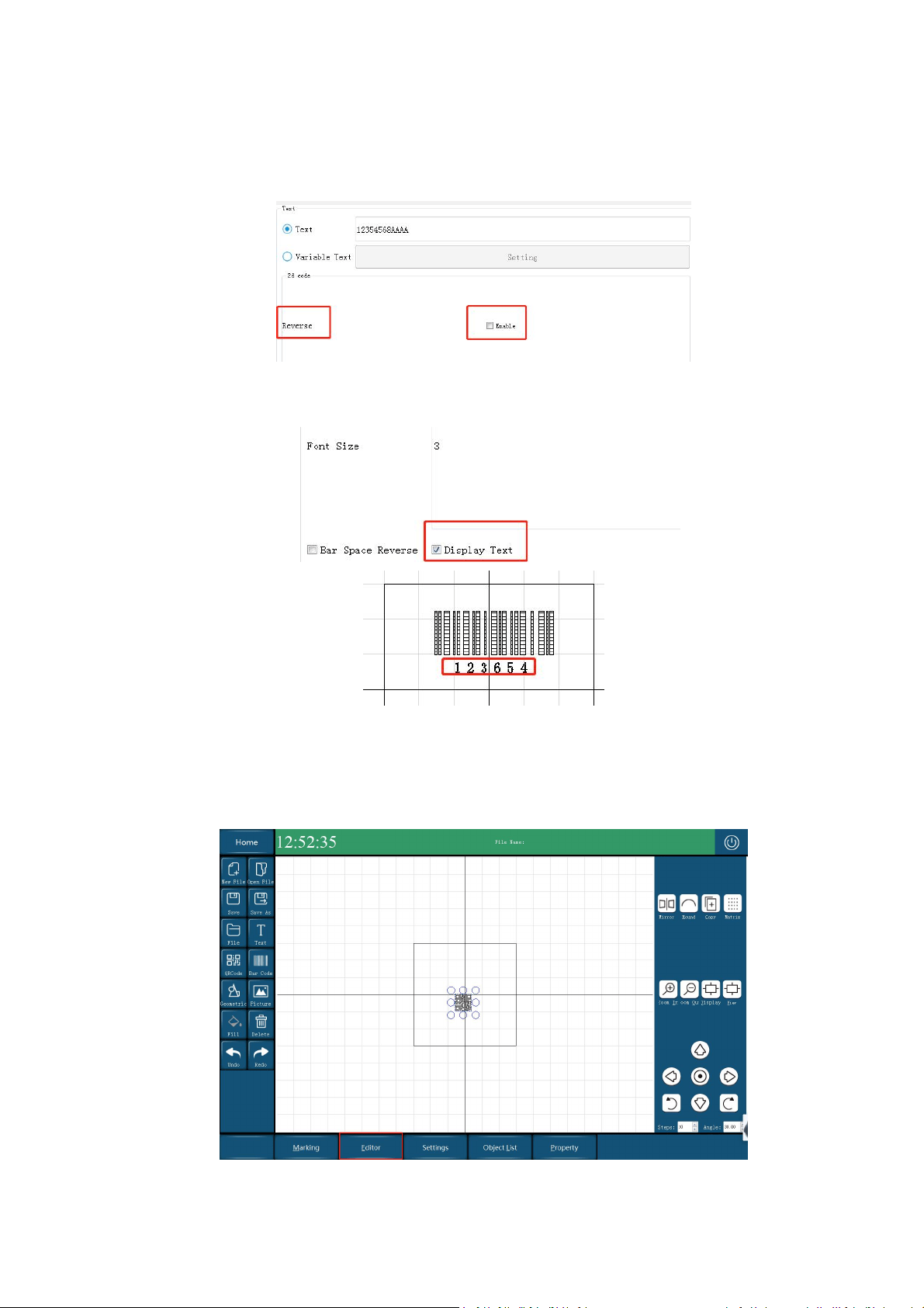
Variable: If content of the QR code is a variable message, select “Variable Text” to enter settings.
For specific variable settings, please refer to "Text Variable Settings"
QR code direction settings
If direction of the QR code should be opposite, then select “Enable”.
Displaying bar code text (this function is invalid for QR codes)
To display the text of the bar code, enable “Display Text”.
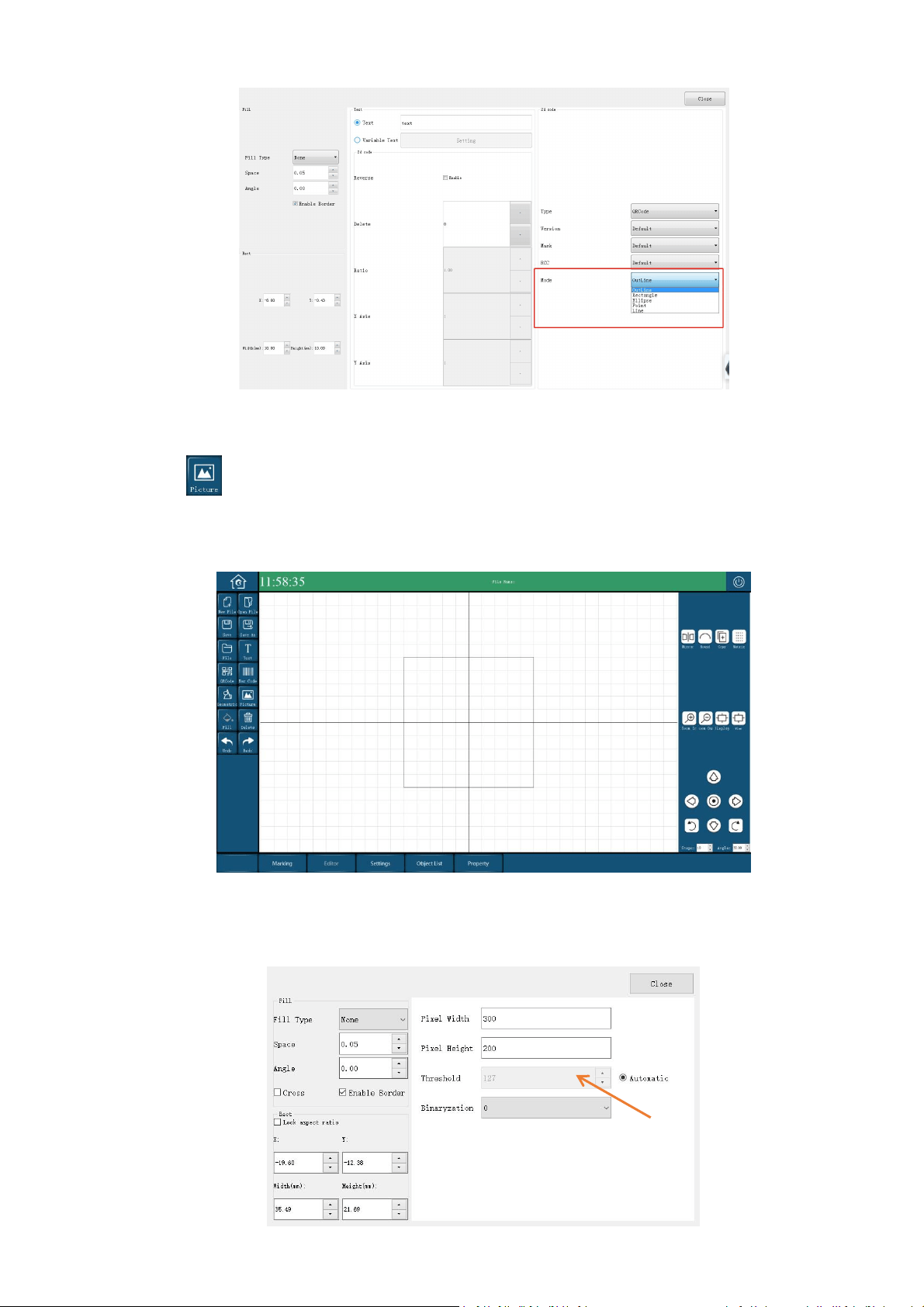
Filling QR Code
There are several types for filling QR code: Outline, Rectangle, Ellipse, Point and Line.
Select “Editor” on the home screen, find the “Mode”, select the pattern to fill the QR code.
PL5 Series Fiber Laser Marking System Page 26 of 40
7. Add an Image
Click on home screen and select a file to add a picture. PL5 laser marking machine only supports
following picture formats
:
PLT、PNG、JPG、JPEG、BMP、 GIF、PBM
Set Threshold of the Image
The threshold is used to determine which colors in the picture are black or white.
PL5 Series Fiber Laser Marking System Page 27 of 40
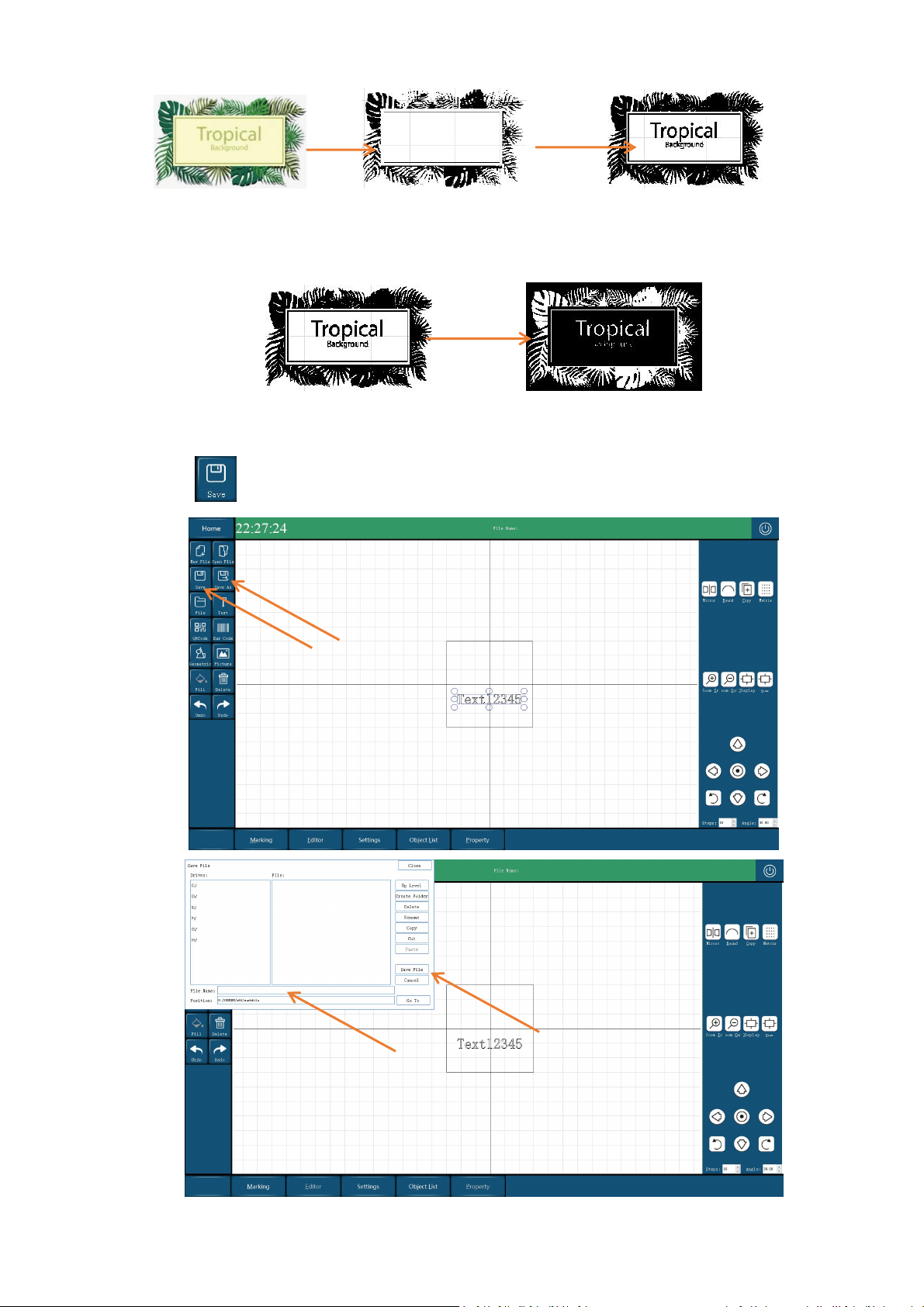
Invert the color of the picture
Set the binaryzation of the image can invert the color of the picture.
8. Saving File
Select to enter settings,enter file name and then click “Save File”, shown as following:
import
set threshold
PL5 Series Fiber Laser Marking System Page 28 of 40
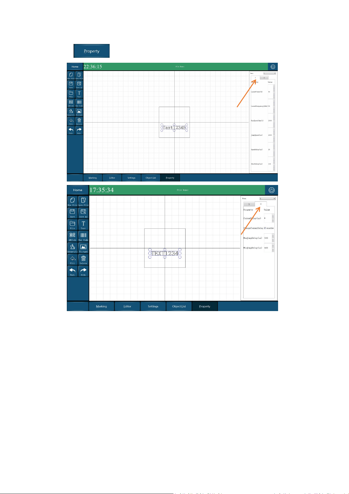
9. Properties And Parameters
Select on the home screen
Laser Power - Unit: %
Set the percentage for the optical output of the fiber laser.The power range is 0% -100%.
However, do not set 100%, it will shorten the lifetime of laser source. Maximum value is better
to set to 95%. The initial value is set to 30%. The greater the value, the deeper the marking.
Laser Frequency - Unit: KHz
It’s pulse frequency, the value range is 1KHz - 100KHz.
The initial value is set to 20 KHz.
Run Speed - Unit: mm/s
Set the speed to be used during marking, the speed range is 1-5000mm/s.
If the mark appears to be faint, reduce this value (note that this will increase the marking time).
Jump Speed - Unit: mm/s.

PL5 Series Fiber Laser Marking System Page 29 of 40
Set the speed to be used between marked vectors (speed at which laser jumps from one vector
to the next. If an object consists of many short polygon strokes, then a large value will make the
mark appear distorted. The value range is 1-5000mm/s, the initial value is set to 2000mm/s.
Jump Delay - Unit: ms.
Jump delay is the time for the laser to jump from one character to the next characters. The
value range is 1-1000. The initial minimum value is set to 400ms, maximum value is set to
500ms.
Jump-Delay too short: the vector following a jump command is already marked at the end
position of the jump-vector during the necessary setting time of the mirrors. Result: an indent
or overshoot becomes visible.
Jump-Delay too long: has no negative effect on the visible scanning result. The time required
increases, however.
Laser-On Delay
Delay in switching the laser on till galvanometer scanning system finish command.
Laser-On-Delay too short: brun-in effects at the starting point
Laser-On Delay too long: Result: the vector are not marked from the starting point.
Laser-Off Delay
Delay in switching the laser off.
Laser-Off Delay too short: the vector are not marked completely.
Laser-Off Delay too long: the vector are not marked from the starting
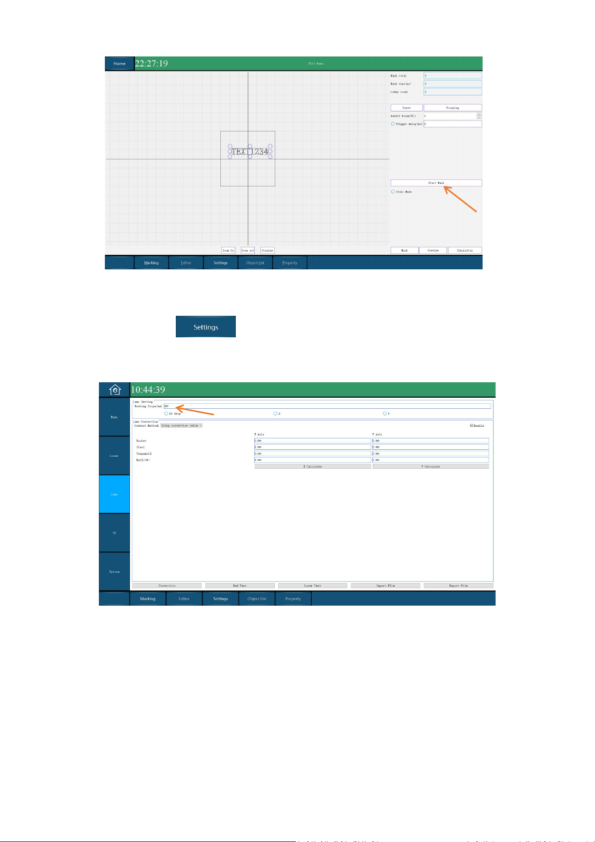
5.3.3 Marking
Select on the home screen, enter to marking screen. Select the parameters needed, and
then click “Start Marking”, press the button on the handler, the printer starts marking.
PL5 Series Fiber Laser Marking System Page 30 of 40
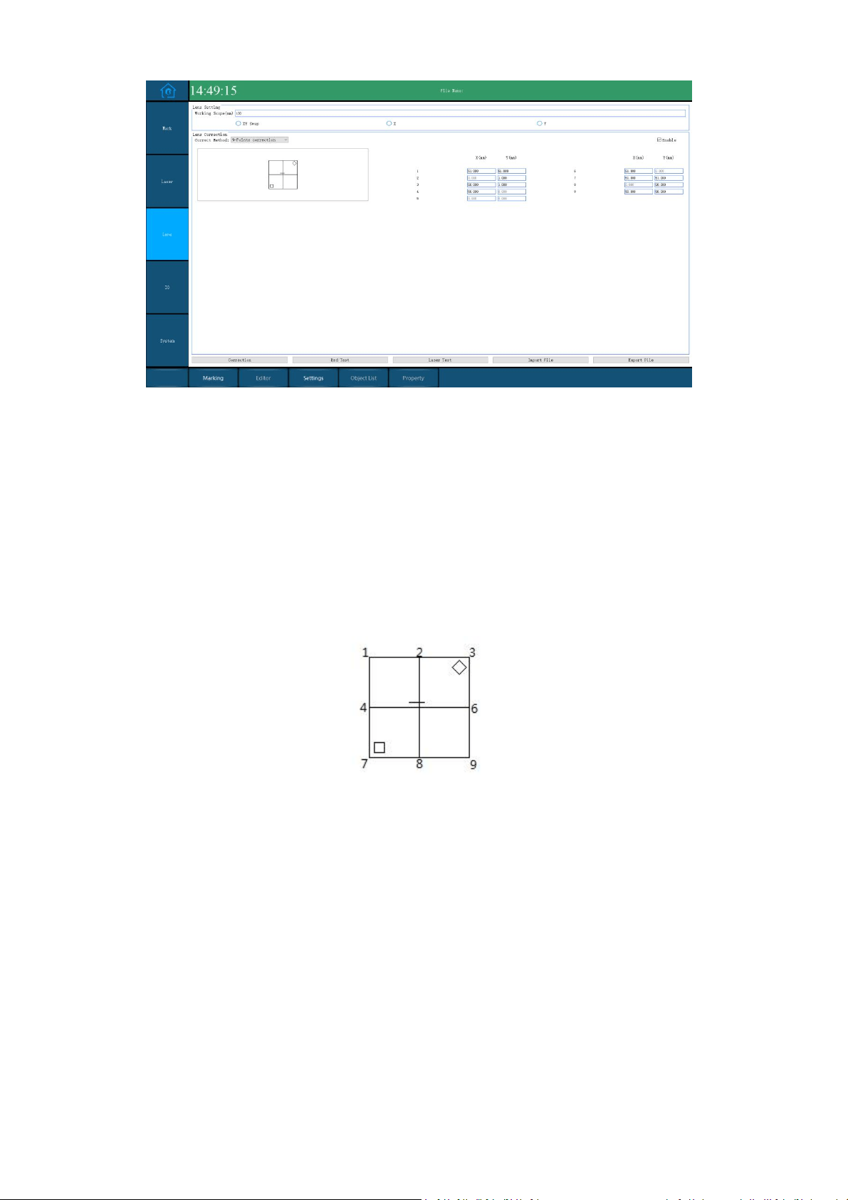
5.3.4 Lens Correction
Select the Settings on the home screen, enter to Settings. Select “Lens”, enter 100 in the
blank of “ Working Scope” (100mm is the size of galvameter scanner), then click “Enable”.
Correct Method #1: Correction Table
Process:
1. First enter the "Working Scope" and go back to the home screen to refresh, and then go
back to the interface shown above.
2. Do not click the "XY Swap", "X", "Y" radio button before correction.
3. Click the "enable" button then click laser test, the machine will print a ‘田’ shape.
PL5 Series Fiber Laser Marking System Page 31 of 40
4. Use a straightedge to measure 4 sides, check whether the sides are aligned with the
straightedge, and whether the 4 corners are 90° right angles. If there is deformation, you
need to enter the corresponding parameters.
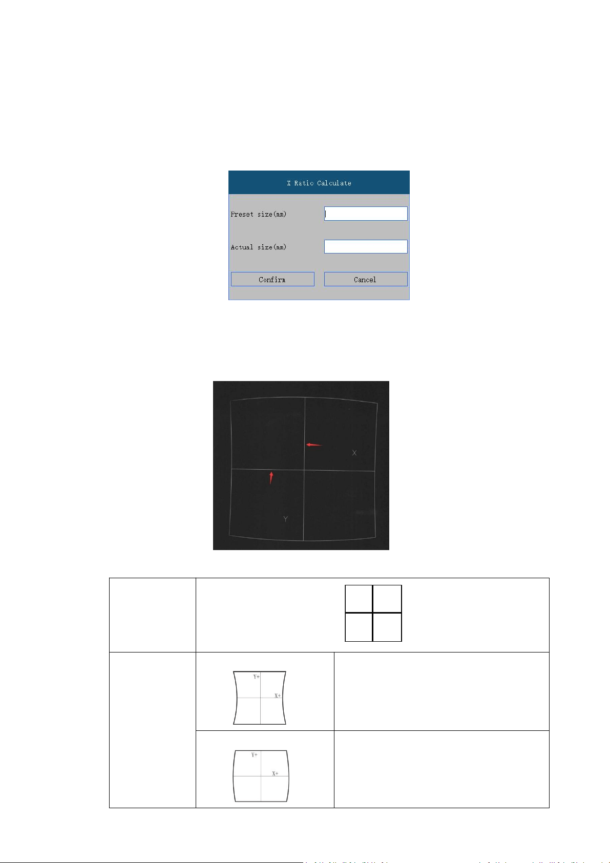
5. Measure the length of the XY axis, click "X Calculate" and "Y Calculate" to input preset
size and actual size. The actual size is the measure size, the preset size is always the same
as work scope(100)
6. Click "Correction" button and type "laser" in the pop-up window to save the correction.
"Bucket", "Slant", "Trapezoid" Param
The XY axis is shown in the figure below:
Target Effect
X-axis bucket
deformation
correction
Decrease the bucket correction value of the X axis,
which can be a negative value
Increase the bucket correction value of the X axis,
which can be a negative value
PL5 Series Fiber Laser Marking System Page 32 of 40
Y-axis bucket
deformation
correction
Decrease the bucket correction value of the Y axis,
which can be a negative value
Increase the bucket correction value of the Y axis,
which can be a negative value
X-axis Slant
deformation
correction
Decrease the SLant correction value of the X axis,
which can be a negative value
increase the SLant correction value of the X axis,
which can be a negative value
Y-axis Slant
deformation
correction
Decrease the SLant correction value of the Y axis,
which can be a negative value
Increase the SLant correction value of the Y axis,
which can be a negative value
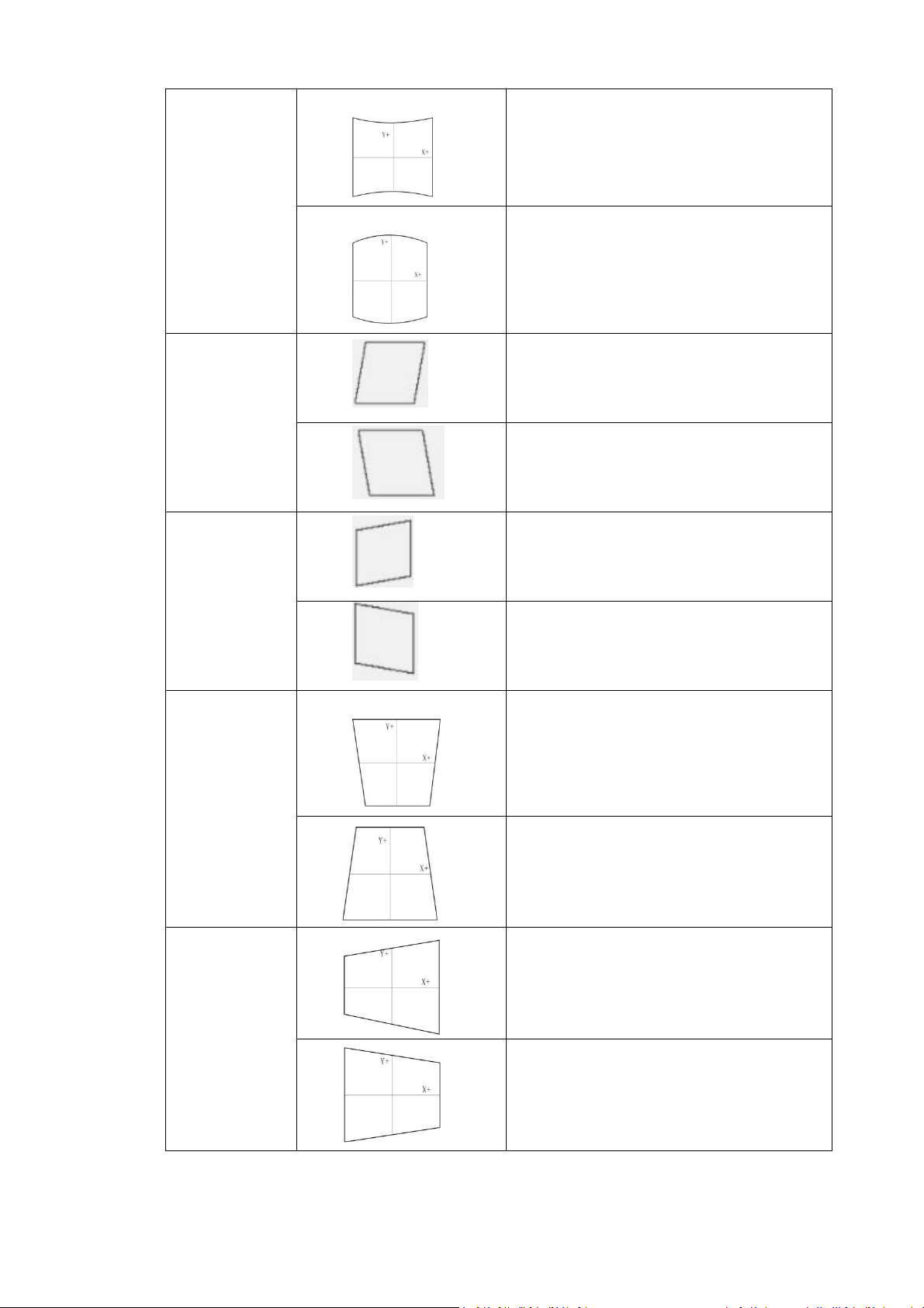
X-axis trapezoid
correction
Decrease the trapezoid correction value of the X
axis, it can be a negative value
Increase the trapezoid correction value of the X
axis, it can be a negative value
Y axis trapezoid
correction
(Trapezoid)
Decrease the trapezoid correction value of the Y
axis, it can be a negative value
Increase the trapezoid correction value of the Y
axis, it can be a negative value
PL5 Series Fiber Laser Marking System Page 33 of 40
Process:
1. First enter the "working Scope" , and click the "Y" radio button.
2. Click the "enable" button.
3. Go back to the home screen to refresh then come back.
4. Click the "laser test" button and the machine will print a ‘田’shape.
5. Put the ‘
田
’shape just printed in the same direction as the ‘
田
’shape in software.
6. Take the center of the crosshair as the zero point and measure the actual positions of the
8 points, then enter the value. The point numbers are shown below. (point 5 is never
change)
7. Click "Correction" button and type "laser" in the pop-up window to save the correction.
5.3.5 Setting
PL5 Series Fiber Laser Marking System Page 34 of 40
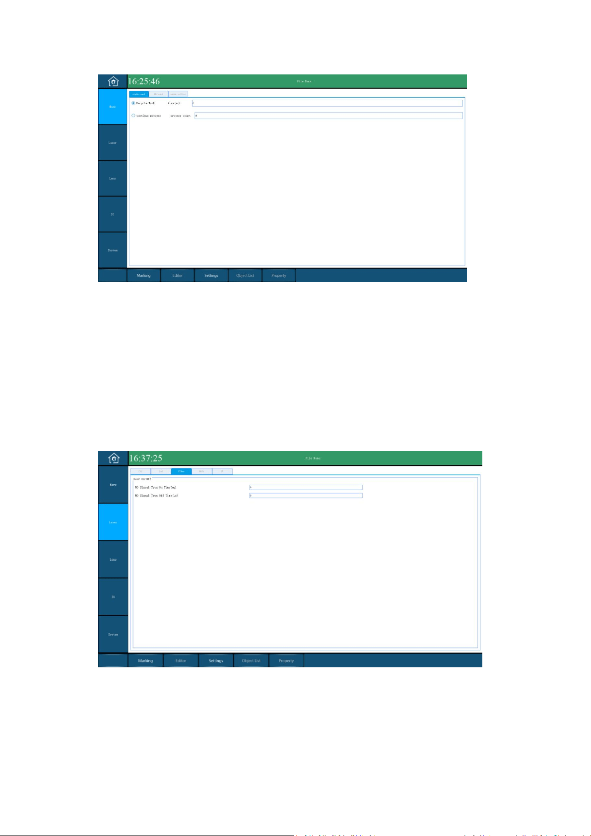
Marking Setting
Recycle Mark: For debugging, do not need to check
time: The pause time for each marking, used in conjunction with continuous marking, the
default is 0
Continue process: Mark multiple times per trigger, do not need to check.
Process count: The number of markings per manual and marking trigger.
Pre-light
NO Signal Turn On Time: Laser gate signal, default 8000
NO Signal Turn Off Time: Laser gate signal, default 8000
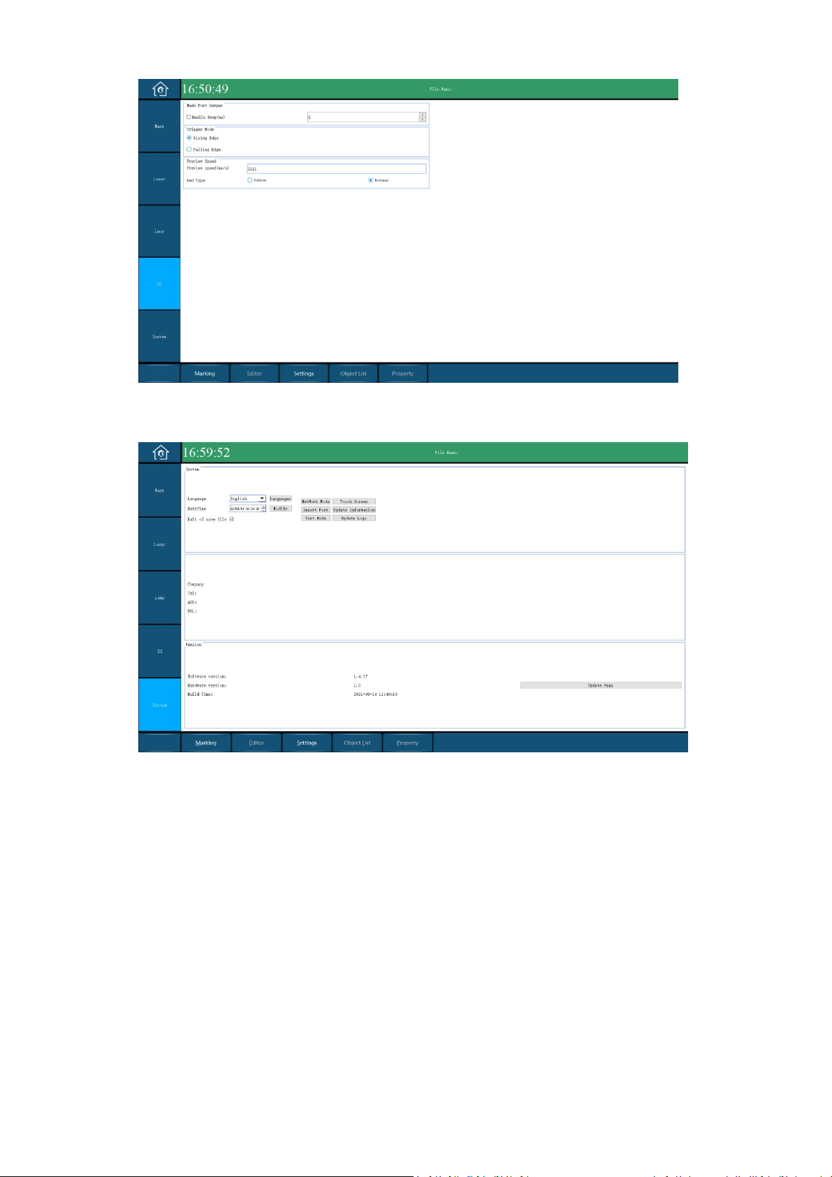
I/O
You can set the beep enable (default) and its duration.
Set the trigger mode: Rising Edge will let the buzzer sound before manual trigger, and the Falling
Edge let the buzzer sound after manual trigger.
You can also set the red light preview speed and red light preview mode here.
PL5 Series Fiber Laser Marking System Page 35 of 40
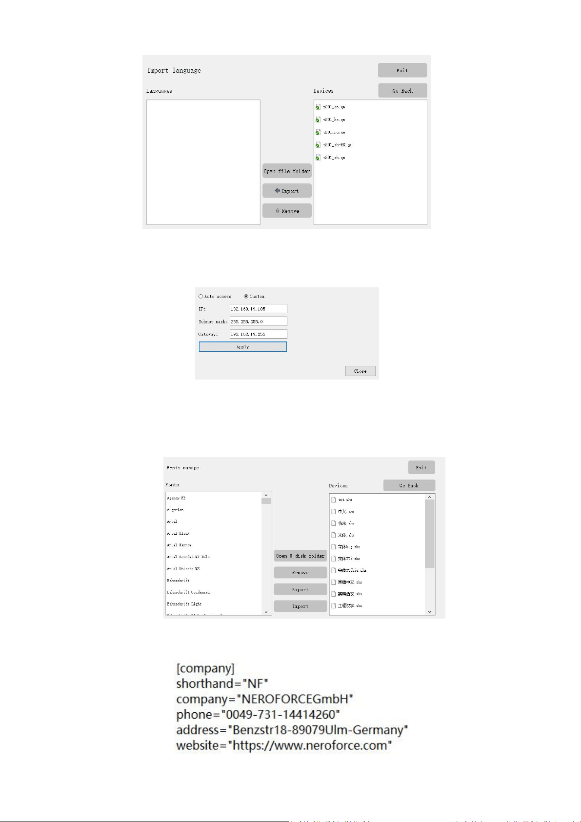
System
Click the Language combo box to change the language of the system, it contains Chinese and
English by default.
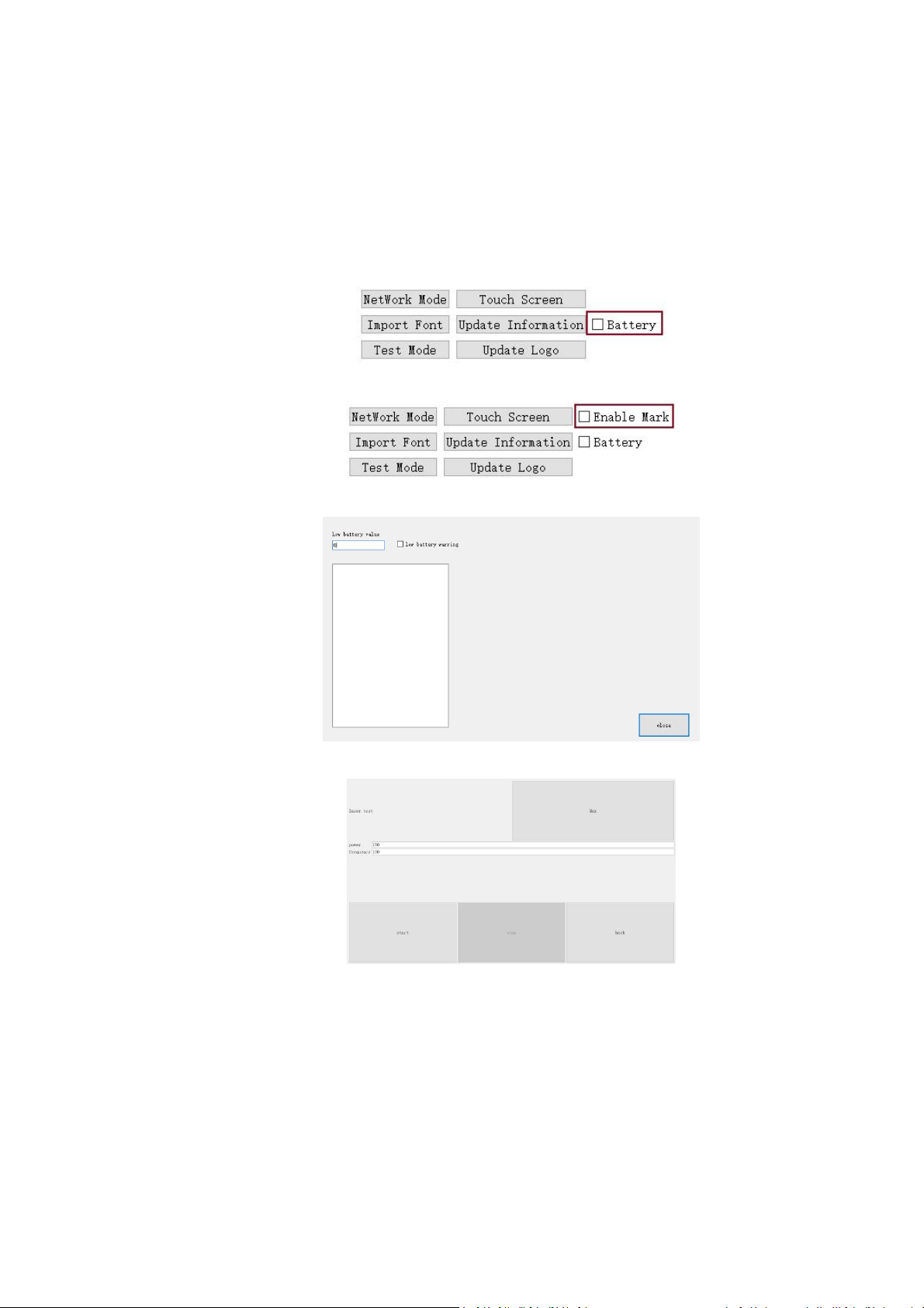
Click the Languages button to import the language package, the format of the language package
is "qm"
PL5 Series Fiber Laser Marking System Page 36 of 40
Change the date time and click modify button to let it take effect.
Check the Exit of save file to save all the change in system.
Click the Network Mode button to set the system network param.
Click the Touch Screen button to make sure that the screen cursor is the same as the touch
position.
Click the Import Font button to import font files, the formats of the font files contains only ttf
and shx.
Click the Update Information button to import you company information, you should write you
company information in a ini file first. The format of the file is shown below:
PL5 Series Fiber Laser Marking System Page 37 of 40
Click Update Logo button to modify the system startup screen logo. Enter the "logo" password,
select your logo then click open button.
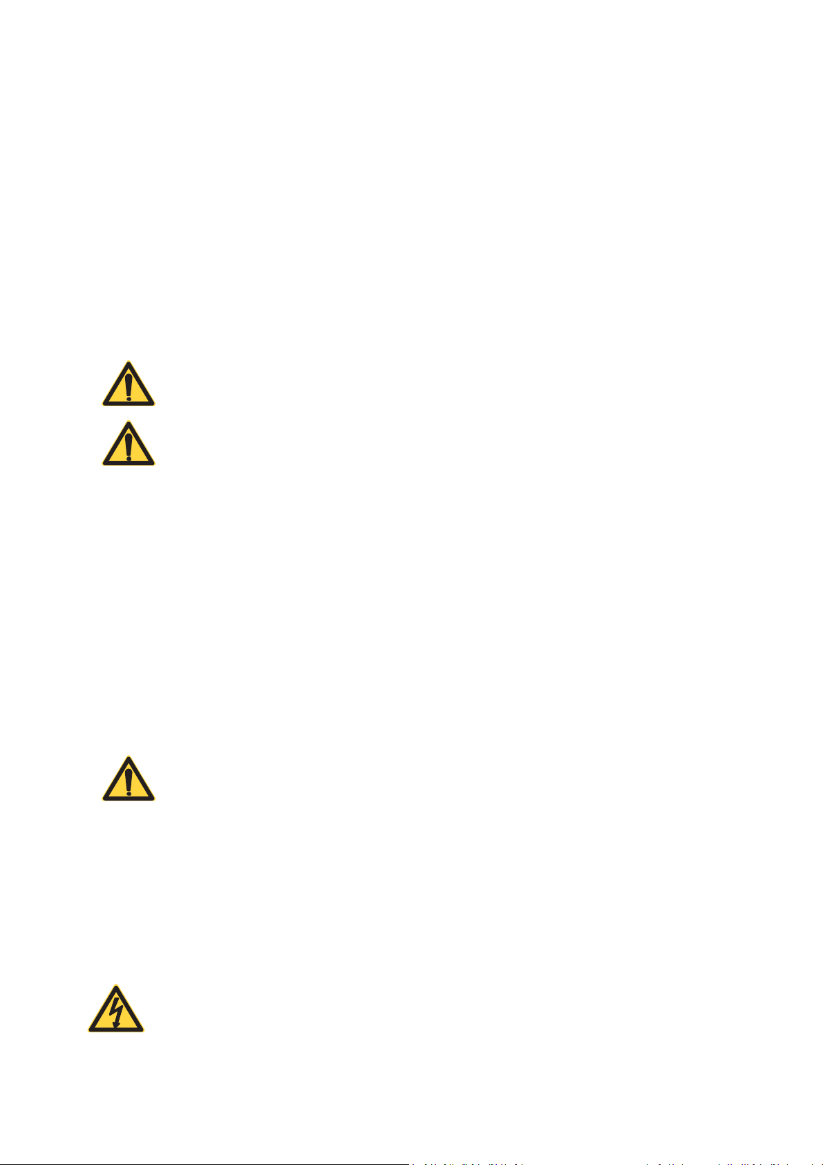
The Password and The Function in Test Mode
Click the Test Mode button and enter different password to test different function.
power: show battery icon on the upper right corner of the screen. (The battery version is
checked by default)
mark: Enable marking function, checked by default.
Set the battery alarm value, set low battery warning and select input method language.
laser: Grow light function, used to test laser power
PL5 Series Fiber Laser Marking System Page 38 of 40
6 MAINTENANCE
6.1 General Notes
In prior to any operation, the user should read this instructions carefully. The laser system is designed
such that maintenance can be performed safely.
In order to achieve the best printing results and prevent damage, the maintenance of the laser system is
very important. It is necessary to establish a maintenance schedule for the laser marking system
considering the working intensity of the equipment and the characteristics of the printed products.
CAUTION
The laser marking system must only be installed and operated by authorised
and specifically trained personnel only.
WARNING
Before performing any maintenance on the laser marking system, ensure
that the system is completely shut down by disconnecting from the power
supply.
6.2 Maintence Procedures
6.2.1 General Maintence Procesures
1. Cut off the main power.
2. Clean the lens when finish using the laser marking system and then cover the lens cover.
Remove dust on the surface of the lens by blowing air with a rubber squeeze bulb. If the lens is
dirt and dusty, clean the lens by folloing section 6.2.2.
CAUTION
The lens of the laser machine should be guaranteed to avoid smoke, dust,
water, oil, scratches and touch. Keep it clean at all times.
3. Clean up the dust accumulated on the air vents on the surface of the machine housing weekly.
4. If the system is not turned on for a long time, it must be powered off, and cover the laser head
and control box with a cover cloth to avoid dust accumulation and moisture-proof.
6.2.2 Clean the Lens
WARNING
Ensure that the system is completely shut down by disconnecting from the
power supply.

PL5 Series Fiber Laser Marking System Page 39 of 40
Note that any dirt, dust and other contaminants on the surface of the beam exit can absorb laser energy
and burn into the surface to damage the optical elements. The warranty does not cover any damage due
to improper use, cleaning or handling.
1. Before cleaning, ensure that the laser system is shut down and can not be accidentally turned
on again.
2. Use clean gloves or finger cots. Avoid touching the mirror with skin as fingerprints contain
aggressive substances that can damage the optical surfaces.
3. If dust particles are inspected, remove them by blowing air on the mirror surface with a rubber
squeeze bulb.
4. If the lens surface is still not clean, use a cotton ball or swab with high-purity isopropanol or
acetone to uniformly clean the surface. Don’t use too much solvent, otherwise drying marks
might appear.
5. If the dust cannot be removed by air, or if inspect more serious contamination, contact Phezer
LASER for guidance. In extreme cases, the lens must be returned to Phezer LASER for inspection
and cleaning.
Phezer recommend to clean the lens by blowing air not less than once per day. The cleaning frequency
depends on the specific environmental conditions of the production site. If there is a lot of smoke and
particles on the production site, the lens will get dirty faster, which requires more frequent cleaning.
Each user should establish corresponding cleaning requirements according to the production situation.

PL5 Series Fiber Laser Marking System Page 40 of 40
7 TROUBLESHOOTING
If problems occur while operating the laser, verify that all operating instructions have been adhered to and then
carry out the following troubleshooting procedures:
NO.
Problem
Possible cause & Remedy
1
The equipment does not start
when powered on
Check whether the circuit is short-circuited
Check whether the circuit is loose
Check whether the battery (power supply) is powered
2
Laser does not emit light
Check whether the laser is powered on successfully
Check whether the focal length is correct
Check whether the through hole is blocked by foreign matters
Check whether the system control line is loose
Check whether the laser control line is loose
3
The galvanometer does not
swing
Check whether the motor on the galvanometer vibrates
Check whether the two motors on the galvanometer are tight
4
Screen problem
If the screen is not lit, check whether 24V power supply is
successful
Check whether the cable is loose or broken
Check whether the screen is cracked
If the touch is not effective, check whether the touch cable has
deep creases and whether it is loose or broken
The screen is black and only the cursor is left. Upgrade the
software again
If the touch does not work, the software interface will be corrected
again
5
The software control does not
emit light
Check whether the pen number parameters are normal (power,
frequency)
Check whether the laser drive is selected normally
6
Font printing broken and has
deformation
Adjust the frequency and scoring speed
Check whether the galvanometer correction is normal. If not,
correct it again