VERSION A0
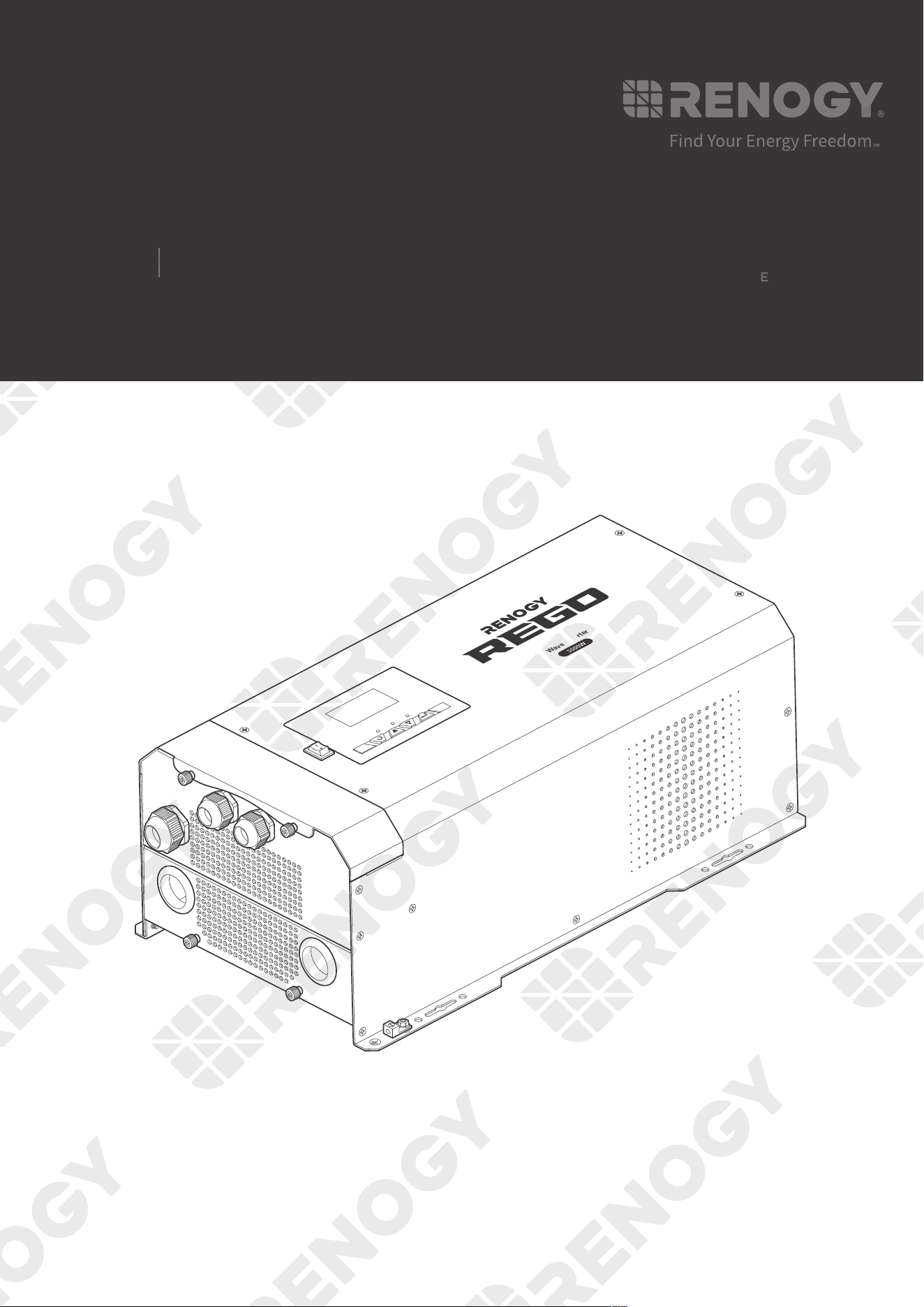
Inverter Charger
REGO
12V 3000W
USER MANUAL
AC / INV
CHC
OFF
ON
FAULT
ARNING
please read the instructions carefully
Before working on this product.
High voltage,in order to avoid risks,
Pure Sine Wave Inverter Charger
02
Applicability
The user manual applies to the following product:
z
REGO 12V 3000W Inverter Charger (RIV1230RCL-1SS-G1)
Disclaimer
z
Renogy makes no warranty as to the accuracy, sufficiency, or suitability of information in the
user manual because continuous product improvements are going to be made.
z
Renogy assumes no responsibility or liability for losses or damages, whether direct, indirect,
consequential, or incidental, which might arise out of the use of information in the user
manual.
z
Renogy is not responsible or liable for the failures, damages, or injuries resulting from repair
attempted by unqualified personnel or improper installation and operation.
z
The illustrations in the user manual are for demonstration purposes only. Details may appear
slightly different depending on product revision and market region.
z
Renogy reserves the right to change the information in the user manual without notice.
Copyright
REGO 12V 3000W Inverter Charger User Manual © 2022 Renogy. All rights reserved. All
information in the user manual is subject to copyright and other intellectual property rights of
Renogy and its licensors. The user manual may not be modified, reproduced, or copied, in
whole or in part, without the prior written permissions of Renogy and its licensors.
Trademarks
The following are trademarks or registered trademarks of Renogy in the United States and other
countries and regions:
RENOGY
All other trademarks in the user manual are the property of their respective owners and their
use herein does not imply sponsorship or endorsement of their products or services. The
unauthorized use of any trademark displayed in the user manual or on the product is strictly
prohibited.
Date and Revision
January 2022, Revision A0
03
Table of Contents
Important Safety Information .......................................................................................................06
Symbols Used .........................................................................................................................06
General Safety Information .....................................................................................................06
Introduction ..................................................................................................................................08
General Information ................................................................................................................08
Key Features ...........................................................................................................................08
Package Contents .......................................................................................................................10
Optional Accessories ...................................................................................................................11
Product Overview ........................................................................................................................12
External View ..........................................................................................................................12
Internal View ............................................................................................................................13
Wiring Diagram ............................................................................................................................14
Recommended Cable Sizing .......................................................................................................15
Components & Tools ...................................................................................................................16
Inspection ....................................................................................................................................19
Inspecting Inverter Charger .....................................................................................................19
Environment ............................................................................................................................19
Placement ...............................................................................................................................20
Checking Battery .....................................................................................................................21
Preparation ..................................................................................................................................23
Mounting .................................................................................................................................23
Removing the Plate .................................................................................................................23
Cautions ..................................................................................................................................24
Ground Cable Wiring ...................................................................................................................25
Remote Control Wiring ................................................................................................................27

04
Temperature Sensor Wiring .........................................................................................................28
Battery Wiring ..............................................................................................................................30
Device-side Wiring ..................................................................................................................30
Battery-side Wiring ..................................................................................................................32
AC Output Wiring.........................................................................................................................38
Device-side Wiring ..................................................................................................................38
Load Wiring .............................................................................................................................39
AC Input Wiring ...........................................................................................................................41
Automatic Generator Start ...........................................................................................................43
Communication............................................................................................................................47
Inter-Device Communication ...................................................................................................47
Monitoring Device Communication .........................................................................................52
Putting Plates Back .....................................................................................................................57
Power on .....................................................................................................................................58
Main Switch .............................................................................................................................58
Wired Remote Control .............................................................................................................59
Operation .....................................................................................................................................60
LCD .........................................................................................................................................60
Button ......................................................................................................................................63
Setting Battery Type ................................................................................................................64
User Mode ...............................................................................................................................67
Working .......................................................................................................................................73
Working Logic ..............................................................................................................................75
Power Supply Logic ................................................................................................................75
Charging Logic ........................................................................................................................75
Heat Dissipation Logic ............................................................................................................77
Power off .....................................................................................................................................78
Main Switch .............................................................................................................................78

05
Wired Remote Control .............................................................................................................78
Overcurrent Protection ................................................................................................................80
LED Indicators .............................................................................................................................81
Indicator of the Inverter Charger ............................................................................................81
Indicator of the Wired Remote Control ....................................................................................81
Program Codes ...........................................................................................................................82
Warning/Fault Codes ...................................................................................................................91
Technical Specifications ..............................................................................................................93
Dimensions ..................................................................................................................................95
Maintenance ................................................................................................................................96
Inspection ................................................................................................................................96
Cleaning ..................................................................................................................................96
Storage ....................................................................................................................................96
Emergency Responses ...............................................................................................................97
Fire ..........................................................................................................................................97
Flooding ..................................................................................................................................97
Smell .......................................................................................................................................97
Noise .......................................................................................................................................97
Technical Support ........................................................................................................................98
06
Important Safety Information
The user manual provides important installation, operation, and maintenance instructions for
REGO 12V 3000W Inverter Charger (hereinafter referred to as inverter charger). Read the user
manual carefully before installation and operation and save it for future reference. Failure to
observe the instructions or precautions in the user manual can result in electrical shock, serious
injury, or death, or can damage the inverter charger, potentially rendering it inoperable. The
installation and service of the inverter charger might require knowledge of high voltage electricity
and is recommended to be carried out by qualified personnel.
Symbols Used
The following symbols are used throughout the user manual to highlight important information:
WARNIN
G
Indicates a potentially dangerous condition which could result in
injury or death.
CAUTIO
N
Indicates a critical procedure for safe and proper installation and
operation.
NOT
E
Indicates an important step or tip for optimal performance.
INFO
Indicates that more information is available in other documents
relating to the subject.
General Safety Information
WARNIN
G
z
The voltage of the inverter charger exceeds the human body safety voltage. Read all
instructions and precautions in the manual before installation.
z
Inspect the inverter charger for any visible damage including cracks, dents, deformation, and
other visible abnormalities before installation.
z
Do not puncture, drop, crush, penetrate, shake, strike, or step on the inverter charger.
z
Do not open, dismantle, repair, tamper with, or modify the components of the inverter
charger.
z
Install the inverter charger on a vertical surface indoors protected from direct sunlight, high
temperature, and water. Make sure there is good ventilation.
z
Keep the inverter charger away from heating equipment.
z
Do not insert foreign objects into the inverter charger.
z
Do not install the inverter charger near flammable fumes or gases.
z
Keep the inverter charger out of the reach of children.
z
Wear proper protective equipment and use insulated tools during installation and operation.
Do not wear metal jewelry, such as necklaces and watches.
z
Do not touch the connector contacts while the inverter charger is in operation.
Important Safety Information
Symbols Used General Safety Information
07
Important Safety Information
z
Disconnect all connectors from the inverter charger before maintenance or cleaning.
z
Risk of electric shock! Be careful when touching bare terminals of the inverter charger as
they may retain high lethal voltages even after power is removed.
z
Do not dispose of the inverter charger as household waste. Comply with local, state, and
federal laws and regulations and use recycling channels as required.
z
In the event of fire, use fire extinguishers suitable for electrical equipment.
z
If the inverter charger is installed improperly on a boat, it may cause damage to the corrosive
agents of the boat. Please have the inverter charger installed by a qualified electrician.
CAUTIO
N
z
Do not expose the inverter charger to flammable or harsh chemicals or vapors.
z
Ensure that there is no water source including downspouts, sprinklers, or faucets above or
near the inverter charger.
z
Ensure that the battery bank is properly connected before installation.
z
Check the installation environment of the inverter charger regularly and keep it clean to
prevent the ventilation holes from being blocked by debris or dust.
Symbols Used General Safety Information
08
Introduction
Introduction
General Information
REGO 12V 3000W Inverter Charger is your off-grid smart living center that revolutionizes
comfort when you live in your off-grid home or RV. The inverter charger can invert DC to AC
and directly supply power to the load, and charge the battery when it is connected to the utility
power.
In addtion, it supports different types of batteries such as AGM, Gel, Sealed Lead Acid (SLA),
and Li. The inverter charger can switch power supply from the utility power to batteries within
10 milliseconds, ensuring a smooth mode switch without powering off the load. The lever style
connectors make AC IN/OUT connections simply and easy. They simplify installation and
shorten the installation time.
The inverter charger can be connected to Renogy devices and smart accessories via Bluetooth
or RV-C. When the inverter charger works in association with the DC Home app, you will
have the same system monitoring wherever you go on your smartphone. With advanced pure
sine wave technology, the inverter charger can protect and extend the life of your electronic
equipment and loads.
Key Features
z
Robust and sleek design
The housing of the inverter charger is made of steel plates to ensure its firmness and a more
fashionable appearance.
z
Intuitive LCD and LED
You can view and check the status displayed on the LCD and LEDs, and modify parameters of
the inverter charger according to the actual use.
z
High quality waveform with little harmonic distortion
Advanced Pure Sine Wave technology provides high-quality AC power equivalent to the grid
power. The voltage increases and decreases in a smooth way with little harmonic distortion.
z
Multi-stage Battery charging
Up to three stage battery charging including bulk, boost, and float as well as equalization for
select battery types
z
Configurable charging current
The maximum charging current of the inverter charger is 75A, adjustable at 5A each time.
The
charging current can be ajusted to satisfy your daily use.
z
Nine preset battery voltages and custom options
The inverter charger is compatible with nine types of batteries to meet your needs in daily use.
You can also customize the battery parameters of the inverter charger.
z
Automatic generator start
The inverter charger is equipped with a set of NO and NC dry contacts, which are used to
connect the generator with automatic start and stop function and automatically charge the
battery, facilitating your daily use.
General Information Key Features
09
Introduction
z
Peak conversion efficiency >90%
The peak conversion efficiency is more than 90% during operation, which reduces the energy
loss.
z
Multiple electronic protections
The inverter charger is equiped with undervoltage protection, overvoltage protection, overload
protection, overtemperature protection, and short circuit protection.
General Information Key Features
10
Package Contents
Package Contents
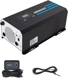
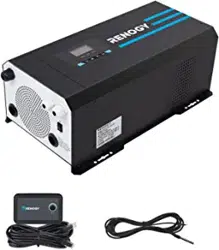
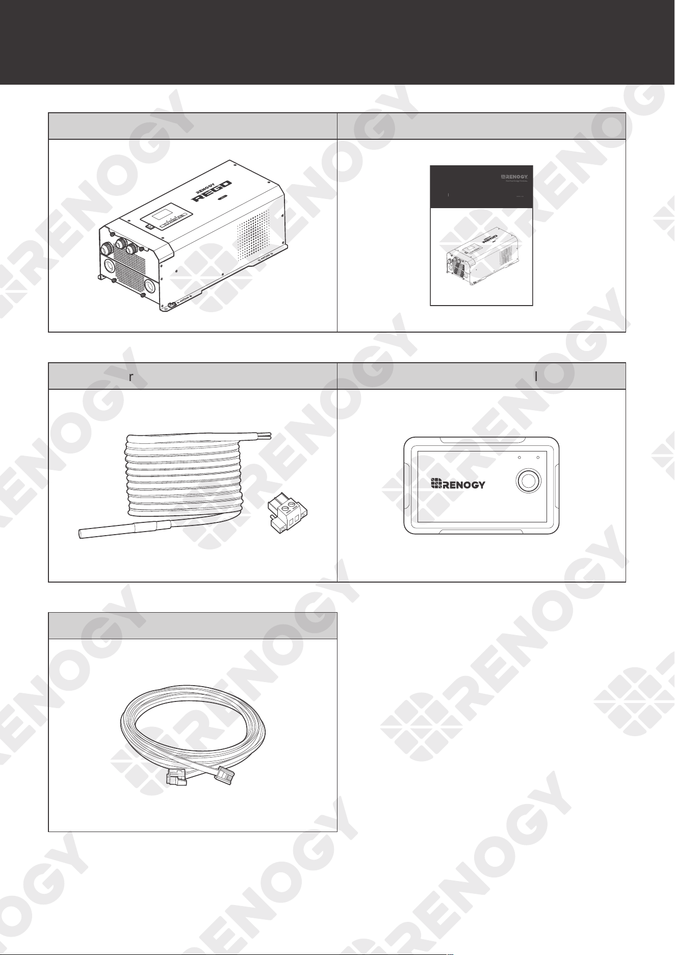
REGO 12V 3000W Inverter Charger × 1 Quick Guide × 1
AC / INV
CHC
OFF
ON
FAULT
ARNING
please read the instructions carefully
Before working on this product.
High voltage,in order to avoid risks,
Pure Sine Wave Inverter Charger
AC / INV
CHC
OFF
ON
FAULT
ARNING
please read the instructions carefully
Before working on this product.
High voltage,in order to avoid risks,
Pure Sine Wave Inverter Charger
VERSION A0
Inverter Charger
REGO
12V 3000W
QUICK GUIDE
Battery Temperature Sensor x 1 Wired Remote Control x 1
ON ERR
RMS-P2
RJ11 Network Cable (5 m) x 1
11
Optional Accessories
Optional Accessories
z
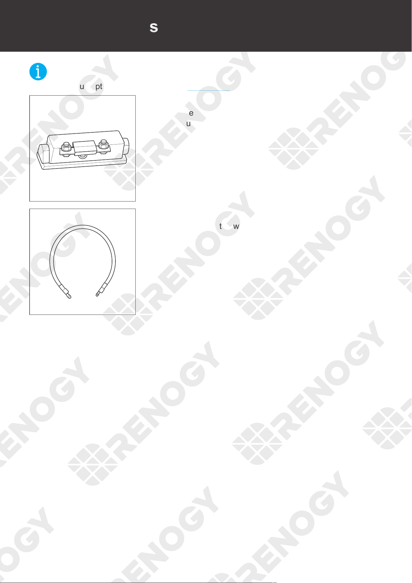
You can buy optional accessories from renogy.com.
DC Fuse (400A)
The DC fuse protects the inverter charger, wires and batteries
from overcurrent.
Fuse Cable 4/0 AWG
The cable is integrated with copper rings at both ends, enabling
the inverter charger to be connected with an external fuse.
NOT
E
12
Product Overview
Product Overview
External View
AC / INV
CHC
OFF
ON
FAULT
ARNING
please read the instructions carefully
Before working on this product.
High voltage,in order to avoid risks,
Pure Sine Wave Inverter Charger
7 8 9
2 3 4 5 61 6
1110
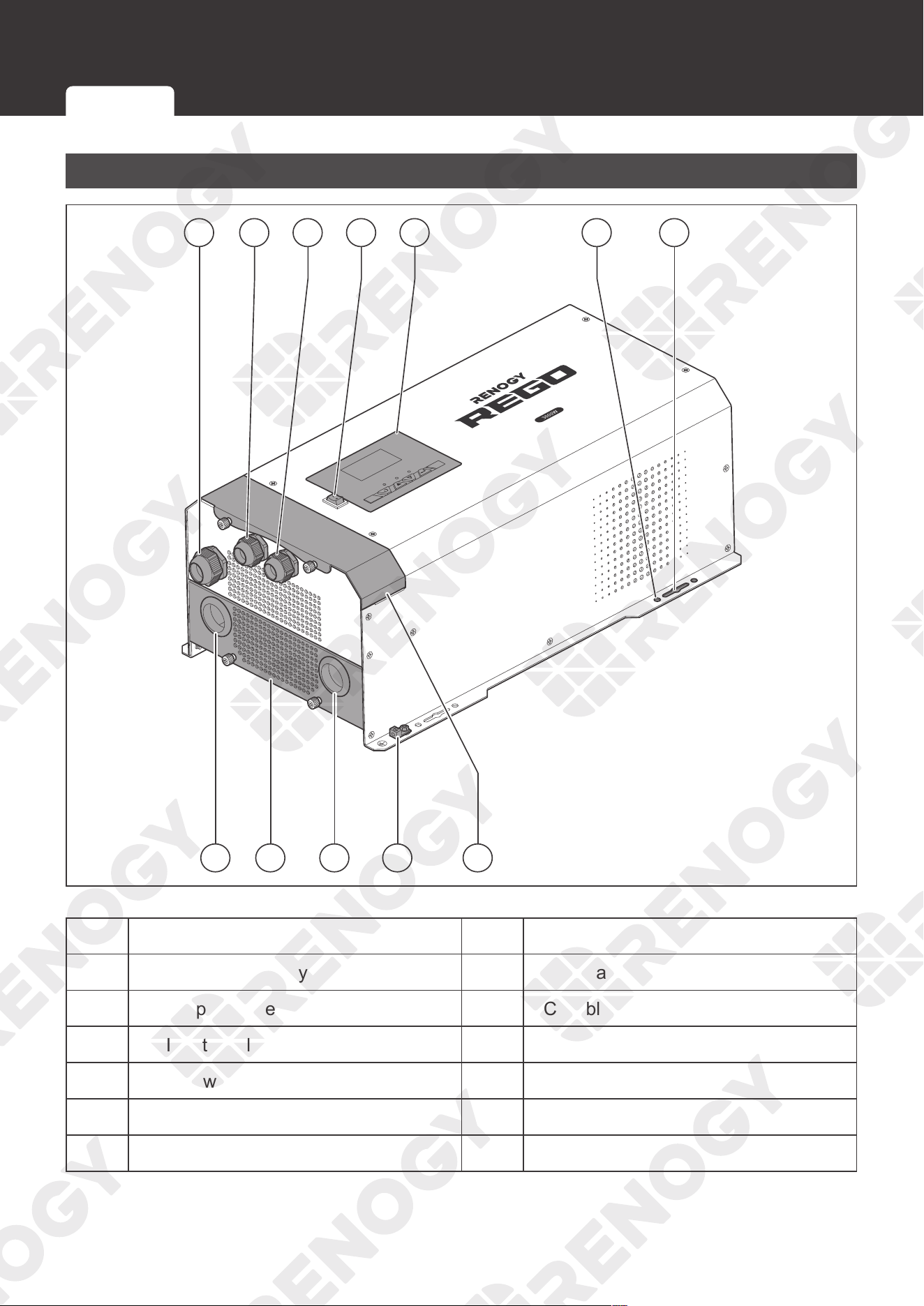
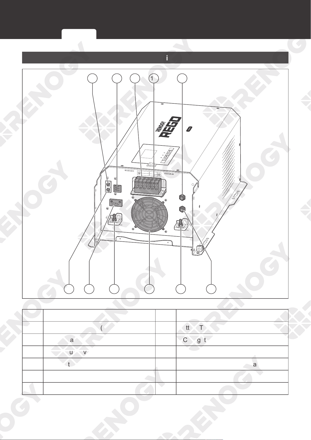
No. Part No. Part
1 Remote & Accessory Cable Entry 7 DC Negative Battery Cable Entry
2 AC Output Cable Grommet 8 DC Cable Plate
3 AC Input Cable Grommet 9 DC Positive Battery Cable Entry
4 Main Power Switch 10 Chassis Ground Lug
5 LCD & Button Panel 11 Top Plate
6 Mounting Holes
External View Internal View
13
Product Overview
Internal View
WARNING
please read the instructions carefully
Before working on this product.
CHARGER INPUT
PROTECT
INVERTER OUTPUT
PROTECT
BTS
NO
NC
DRY
OUTPUT
INPUT
N
N
L
L
CONTACT
REMOTE
C
CAN
High voltage,in order to avoid risks,
AC/INV
OFF
ON
CHC
FAULT
Pure Sine Wave Inverter Charger
GITIVE
ATIVE
14 15 1613
18 19 20 21 22
12
17
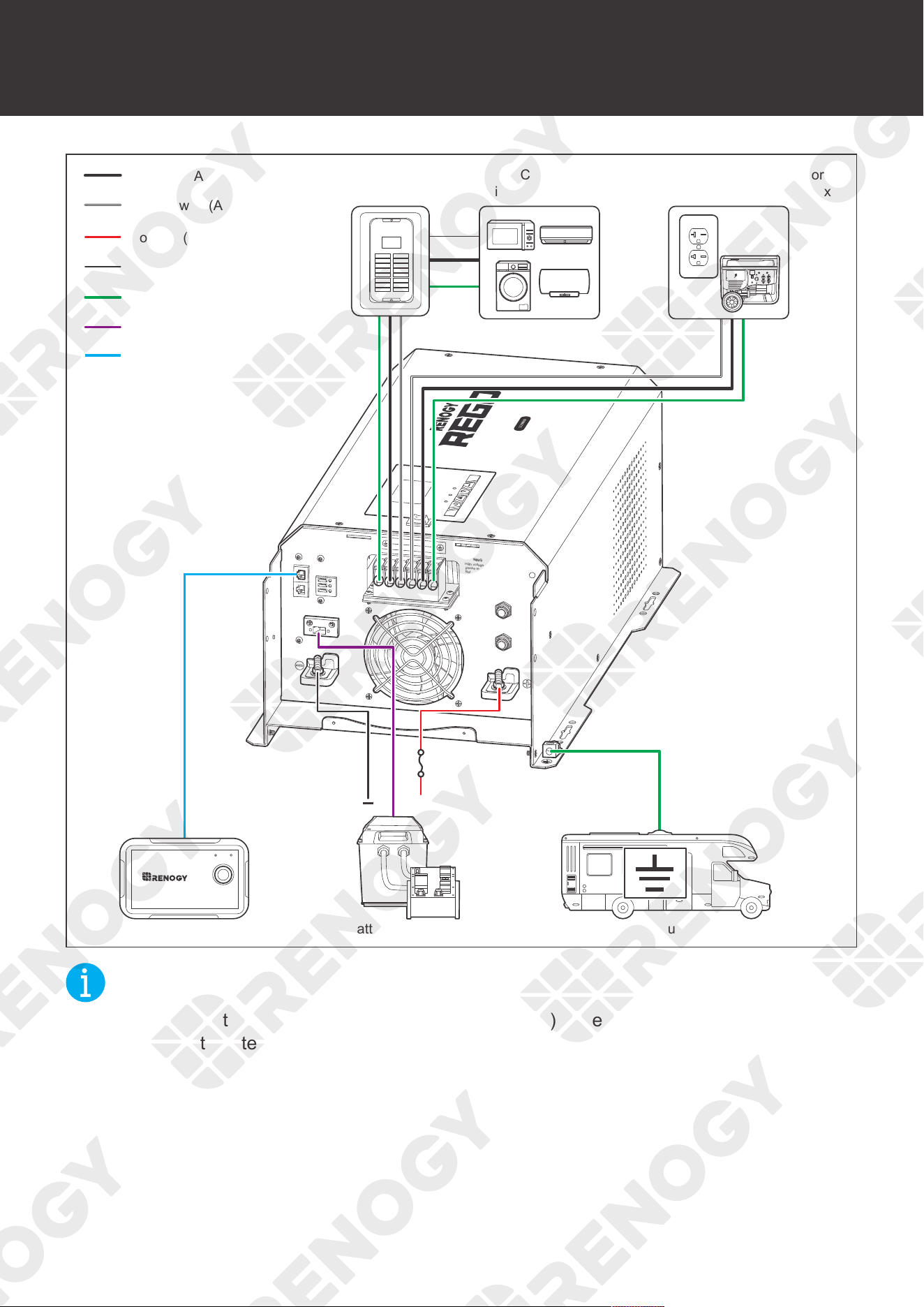
No. Part No. Part
12 Wired Remote Port (REMOTE) 18 Battery Temperature Sensor (BTS) Port
13 Dry Contact Relay Terminal Block 19 DC Negative Battery Terminal
14 AC Output Lever Terminal Block 20 Fan
15 AC Input Lever Terminal Block 21 DC Positive Battery Terminal
16 Input Circuit Breaker 22 Output Circuit Breaker
17 Communication Port (CAN Bus)
External View Internal View
14
Wiring Diagram
Wiring Diagram
WARNING
please read the instructions carefully
Before working on this product.
CHARGER INPUT
PROTECT
INVERTER OUTPUT
PROTECT
BTS
NO
NC
DRY
OUTPUT
INPUT
N
N
L
L
CONTACT
REMOTE
C
CAN
High voltage,in order to avoid risks,
AC/INV
OFF
ON
CHC
FAULT
Pure Sine Wave Inverter Charger
GITIVE
ATIVE
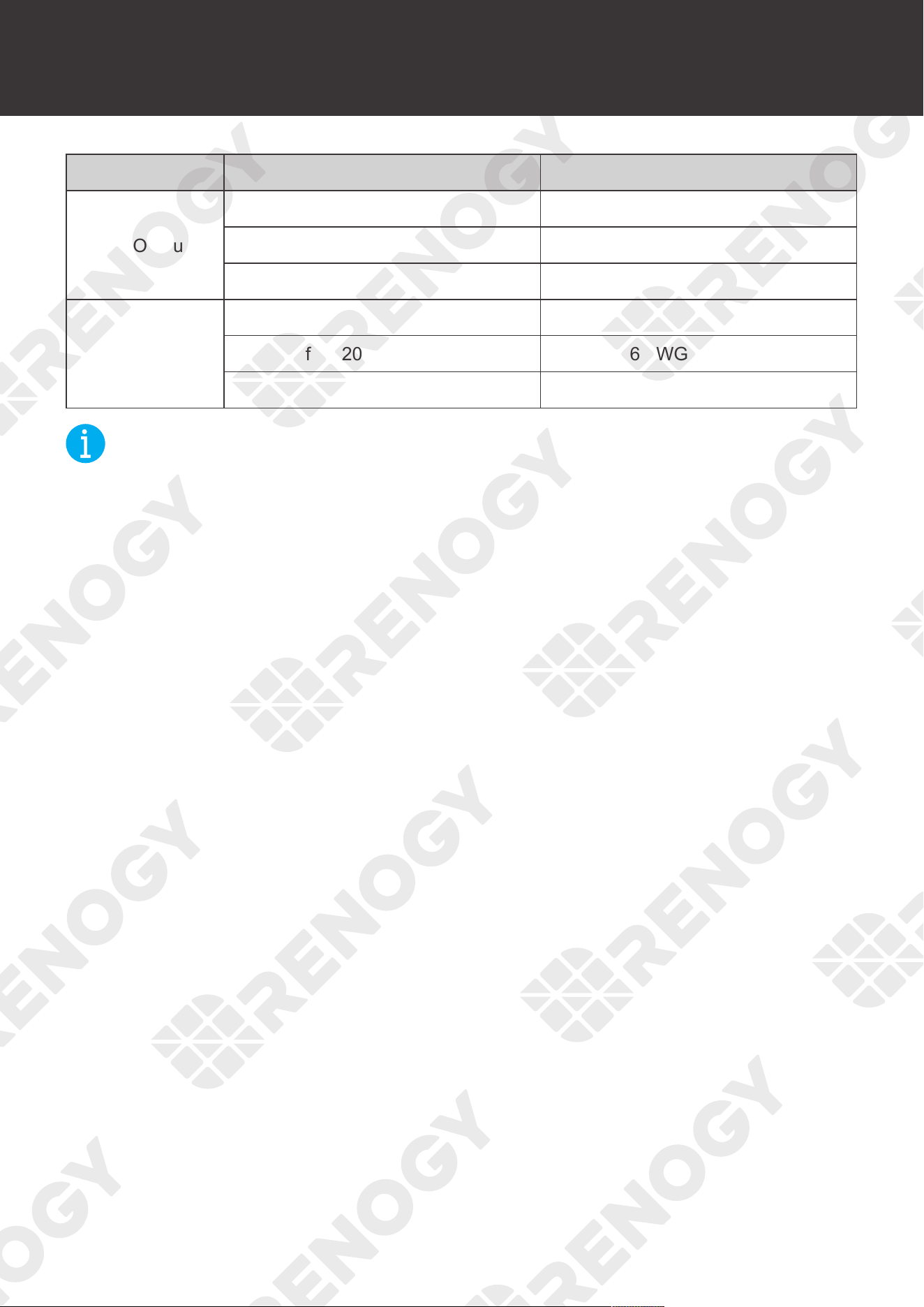
Remote control
Temperature sensor
Ground
Negative (DC)
Positive (DC)
Shore Power or Generator
(120V Single Phase, 40A Max.)
AC Load Center
AC Loads
(120V Single Phase, 30A Max.)
Battery System (12V)
DC Fuse
(400A)
Chassis Ground Lug
+
Wired Remote Control
ON ERR
RMS-P2
Neutral wire (AC)
Live wire (AC)
NOT
E
z
Do not use the temperature sensor on a LiFePO4 (LFP) battery which comes with a Battery
Management System (BMS).
15
Recommended Cable Sizing
Recommended Cable Sizing
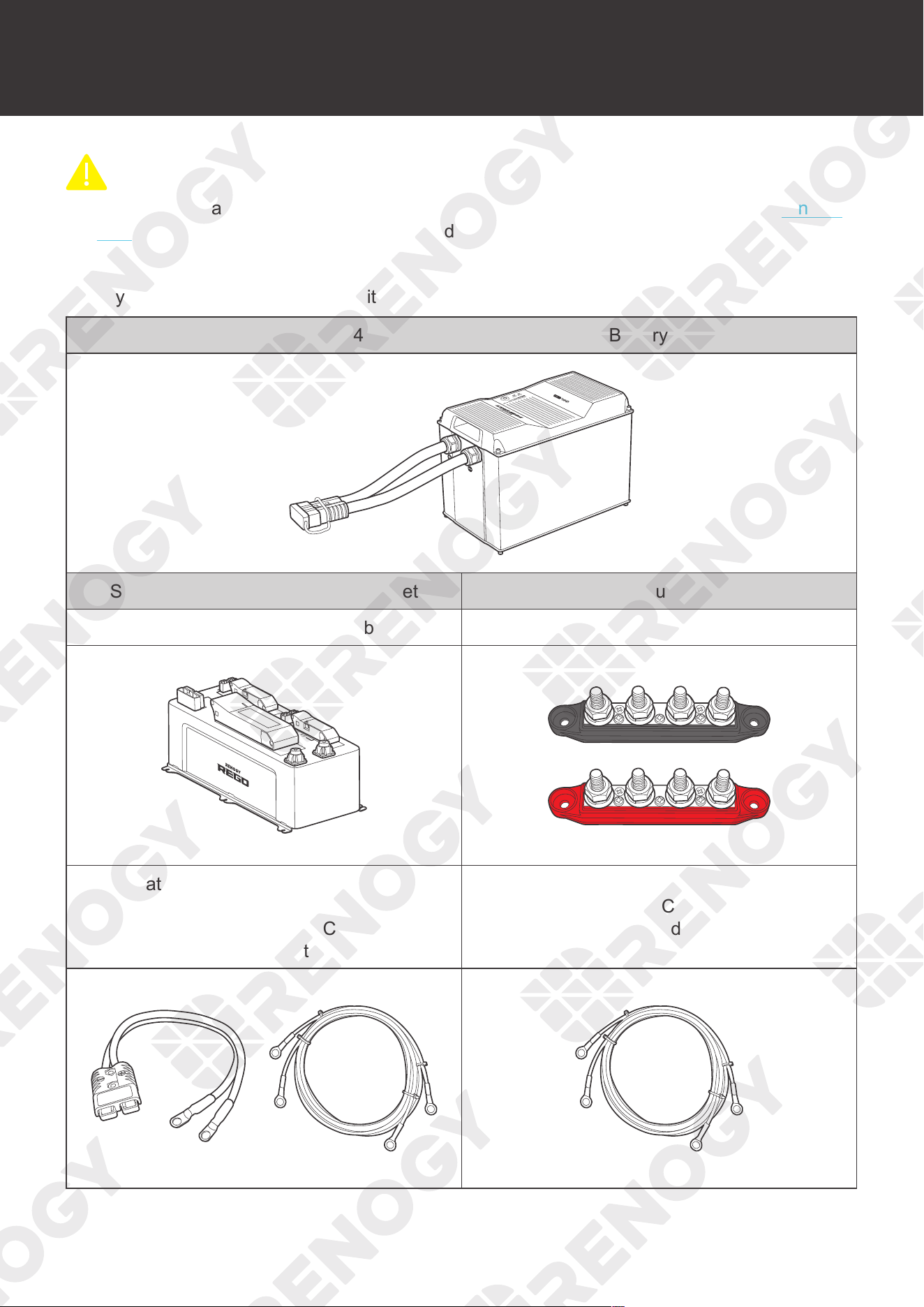
Cable Cable Length (ft) / (m) Recommended Cable Size
AC Output
0 ft to 10 ft (0 m to 3 m) 8 AWG
11 ft to 20 ft (3 m to 6 m) 6 AWG
21 ft to 30 ft (6 m to 9 m) 6 AWG
AC Intput
0 ft to 10 ft (0 m to 3 m) 8 AWG
11 ft to 20 ft (3 m to 6 m) 6 AWG to 8 AWG
21 ft to 30 ft (6 m to 9 m) 6 AWG
NOT
E
z
The cable specifications listed above account for critical, less than 3% voltage drop and may
not account for all configurations.
16
Components & Tools
Components & Tools
CAUTIO
N
z
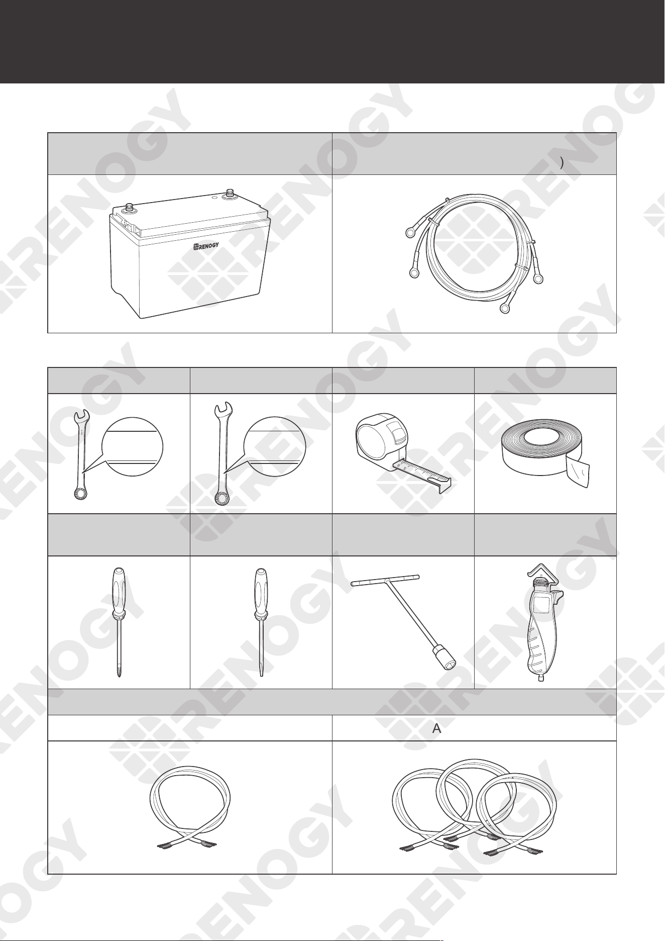
The adapter cable used in this manual can be made by yourself or purchased from renogy.
com by searching names in Recommended Components.
Recommended Components
Battery Scenario A: REGO Battery Kit
REGO 12V 400Ah Lithium Iron Phosphate Battery
System Combiner Box Accessory Set Positive / Negative Busbars Accessory Set
REGO 4 Ports 400A System Combiner Box Positive / Negative Busbars
DC-DC Charger
Inverter
Battery Adapter Cable 4/0 AWG
(Anderson 350 Connector to
Ring Terminal Adapter Cable or
Ring Terminal Adapter Cable)
Battery Inverter Cable 4/0 AWG
(Ring Terminal Adapter Cable)
17
Components & Tools
Battery Scenario B: Normal Battery Kit
Normal Battery with +/- Bolts
Battery Inverter Cable 4/0 AWG
(Ring Terminal Adapter Cable)
+
-
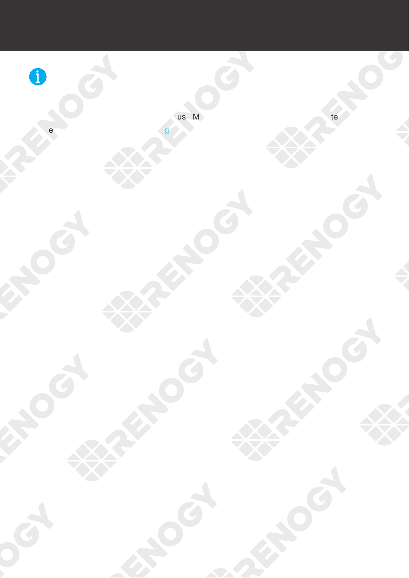
Required Tools
Wrench (10 mm) Wrench (14 mm) Measuring Tape Insulation Tape
10mm
10mm
10mm
14mm
14mm
14mm
3
4
5
6
Phillips Screwdriver
(6 mm)
Slotted Screwdriver
(6 mm)
Socket Wrench
(12 mm)
Wire stripper
Bare Wire
Grounding (6 AWG to 8 AWG) AC Output x 3
18
Components & Tools
NOT
E
z
The AC Output Cable Grommet has an inner diameter of 13 mm. Properly select the AC
cable size and ensure it can run through the grommet.
z
The DC Positibe/Negative Terminals use M8 Studs. Select the appropriate ring terminal.
z
Read Recommended Cable Sizing in this manual, and select the appropriate cables
according to actual use.
19
Inspection
Inspection
Inspecting Inverter Charger
AC / INV
CHC
OFF
ON
FAULT
ARNING
please read the instructions carefully
Before working on this product.
High voltage,in order to avoid risks,
Pure Sine Wave Inverter Charger
1. Inspect the inverter charger for any visible damage including
cracks, dents, deformation, and other visible abnormalities.
All connector contacts shall be clean, dry, and free of dirt
and corrosion.
WARNIN
G
z
Do not use the inverter charger if it has any visible damage.
Environment
Install the inverter charger on a flat surface indoors protected from direct sunlight, high
temperature, and water. Make sure there is good ventilation.
Make sure that the inverter charger is installed in a place at ambient temperature from -4
°
F to
104
°
F or -20
°C
to 40
°C
and relative humidity between 0% and 95% no condensation.
NOT
E
z
Install the inverter charger as close to the battery as possible to avoid voltage drops due to
long cables.
WARNIN
G
z
Risk of explosion! Never install the inverter charger in a sealed enclosure with flooded
batteries! Do not install it in a confined area where battery gases can accumulate.
Inspecting Inverter Charger
Environment Placement
Checking Battery
20
Inspection
Placement
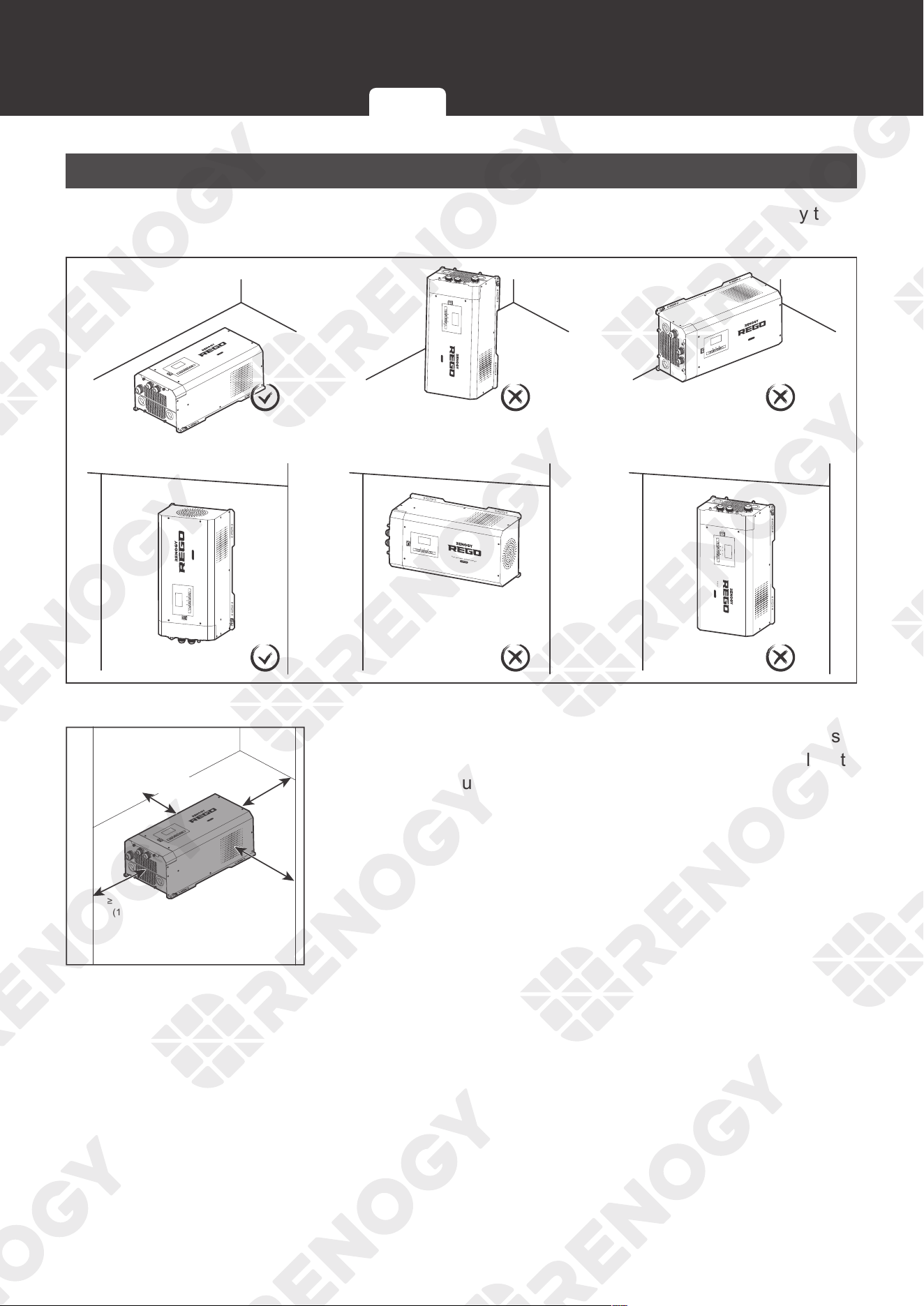
The inverter charger can be fixed vertically (terminals facing down) to a wall or horizontally to
the floor.
AC / INV
CHC
OFF
ON
FAULT
ARNING
please read the instructions carefully
Before working on this product.
High voltage,in order to avoid risks,
Pure Sine Wave Inverter Charger
Pure Sine Wave Inverter Charger
AC / INV
ON
OFF
CHC
FAULT
3000W
Pure Sine Wave Inverter Charger
AC / INV
ON
OFF
CHC
FAULT
3000W
Pure Sine Wave Inverter Charger
3000W
AC / INV
ON
OFF
CHC
FAULT
Pure Sine Wave Inverter Charger
3000W
AC / INV
ON
OFF
CHC
FAULT
Pure Sine Wave Inverter Charger
AC / INV
ON
OFF
CHC
FAULT
3000W
AC / INV
CHC
OFF
ON
FAULT
ARNING
please read the instructions carefully
Before working on this product.
High voltage,in order to avoid risks,
Pure Sine Wave Inverter Charger
≥178mm
(7in)
≥178mm
(7in)
≥254mm
(10in)
≥254mm
(10in)
1. Ensure enough space to avoid tangles and kinks of cables.
Allow at least 10 inches of clearance at the fan and at least
7 inches around each side. It is better to have a larger
ventilation gap. Do not obstruct the fan openings.
Inspecting Inverter Charger
Environment
Placement Checking Battery
21
Inspection
AC / INV
CHC
OFF
ON
FAULT
ARNING
please read the instructions carefully
Before working on this product.
High voltage,in order to avoid risks,
Pure Sine Wave Inverter Charger
2. Measure the length of the
adapter cable to make
sure it can be connected
to the inverter charger.
NOT
E
z
If the adapter cable is not long enough, reselect the installation site.
AC / INV
CHC
OFF
ON
FAULT
ARNING
please read the instructions carefully
Before working on this product.
High voltage,in order to avoid risks,
Pure Sine Wave Inverter Charger
AC / INV
OFF
ON
3. After the installation site
is determined, rock the
main switch of the inverter
charger to the "OFF"
position and keep it until
the inverter charger is
ready to be powered on.
Checking Battery
+
-
1. Inspect the battery for any visible damage including cracks,
dents, deformation, and other visible abnormalities. All
connector contacts shall be clean, dry, and free of dirt and
corrosion.
INF
O
z
Read the user manual of the battery carefully before installation.
Inspecting Inverter Charger
Environment
Placement Checking Battery
22
Inspection
NOT
E
z
Make sure the battery is working normally.
z
Battery types supported by the inverter charger: AGM/Gel/SLA/Open Lead Acid Fooded/
Calcium/De-sulphation/Li.
z
Take care to use a high-capacity lead-acid battery. Be sure to wear protective goggles. If
carelessly getting electrolyte in your eyes, flush your eyes with clean water immediately.
CAUTIO
N
z
Comply with local, state, and federal laws and regulations and use recycling channels as
required when disposing of unwanted batteries.
WARNIN
G
z
Do not use the battery if it has any visible damage.
z
Do not touch the exposed electrolyte or powder if the battery housing is damaged.
z
When being charged, the battery may give off explosive gas. Make sure there is good
ventilation.
Battery or Battery Bank System Voltage
Battery or Battery Bank System Voltage = System Voltage U
Batteries in Series Batteries in Parallel
System Voltage U: U
1
+U
2
+U
3
System Voltage U: U
1
=U
2
=U
3
2. Combine batteries in
parallel or in series as
needed. This inverter
charger supports 12V
batteries. Read the user
manual for battery voltage
parameters, and calculate
the battery or battery bank
system voltage according
to the formula to ensure
that it is 12V.
NOT
E
z
In the formula, U represents the battery voltage, and 1, 2 or 3 represents the battery number
respectively.
WARNIN
G
z
Do not use the inverter charger if the battery/battery bank system voltage exceeds 12V.
Doing so will cause damage to the inverter charger.
Inspecting Inverter Charger
Environment Placement
Checking Battery
23
Preparation
Mounting
Recommended Accessories
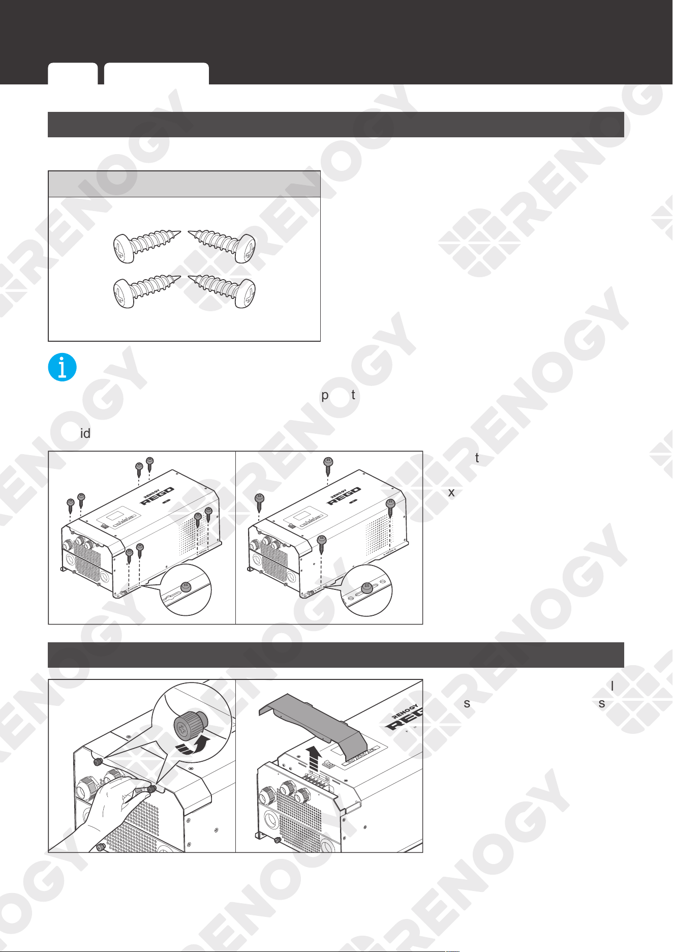
Self-tapping Screws (M8 or M6)
NOT
E
z
Choose proper self-tapping screws to adapt to the installation site.
z
Make sure the inverter charger is firmly mounted on the installation site to prevent it from
sliding or falling off.
AC / INV
CHC
FAULT
ARNING
please read the instructions carefully
Before working on this product.
High voltage,in order to avoid risks,
Pure Sine Wave Inverter Charger
M6
ARNING
please read the instructions carefully
Before working on this product.
High voltage,in order to avoid risks,
AC / INV
CHC
FAULT
ARNING
please read the instructions carefully
Before working on this product.
High voltage,in order to avoid risks,
Pure Sine Wave Inverter Charger
M8
ARNING
please read the instructions carefully
Before working on this product.
High voltage,in order to avoid risks,
OFF
ON
OFF
ON
Align the inverter charger
with the mounting position to
fix it with self-tapping screws
through the mounting holes.
Removing the Plate
CHARCER W
PROT
REMOTE
AC / INV
CHC
FAULT
WARNING
please read the instructions carefully
Before working on this product.
High voltage,in order to avoid risks,
WARNING
please read the instructions carefully
Before working on this product.
High voltage,in order to avoid risks,
Pure Sine Wave Inverter Charger
L
L
N
OUTPUT
INPUT
N
AC / INV
CHC
OFF
ON
FAULT
ARNING
please read the instructions carefully
Before working on this product.
High voltage,in order to avoid risks,
Pure Sine Wave Inverter Charger
ON
ARNING
High voltage,in order to avoid risks,
OFF
ON
1. Turn the two upper panel
screws counterclockwise
by hand or a Phillips
screwdriver, and remove
the Top Plate.
Preparation
Mounting Removing the Plate Cautions
24
Preparation
AC / INV
CHC
FAULT
REMOTE
DRY
CAN
NO
NC
C
CONTACT
CHARCER W
PROT
WARNING
please read the instructions carefully
Before working on this product.
High voltage,in order to avoid risks,
L
L
N
OUTPUT
INPUT
N
NEGATIVE
WARNING
please read the instructions carefully
Before working on this product.
High voltage,in order to avoid risks,
CHARCER W
PROT
REMOTE
AC / INV
WARNING
please read the instructions carefully
Before working on this product.
High voltage,in order to avoid risks,
WARNING
please read the instructions carefully
Before working on this product.
High voltage,in order to avoid risks,
L
L
N
OUTPUT
INPUT
N
OFF
ON
OFF
ON
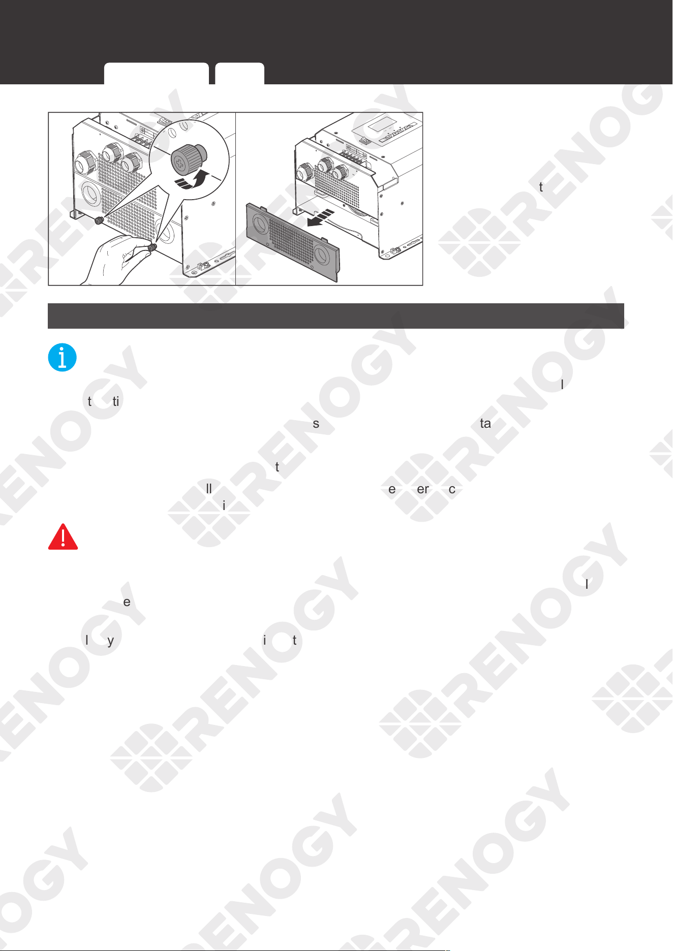
2. Turn the two screws
on the lower panel
counterclockwise by hand
or a Phillips screwdriver,
and remove the DC Cable
Plate.
Cautions
NOT
E
z
All wiring should be done by qualified personnel to ensure compliance with all applicable
installation code and regulations.
z
Wear proper protective equipment and use insulated tools during installation.
z
Ensure that all ring terminals are securely connected.
z
Make sure all cables have a smooth bend radius and no kinks are present.
z
Color code and label all AC Cables coming to/from the inverter charger. Use colored
electrical tape or heat shrink tubing.
WARNIN
G
z
Risk of electric shock! Ensure that all power sources are disconnected before installation.
z
Make sure that all adapter cables are not connected to any device before connection. If they
are connected, make sure that all power devices are powered off.
z
Identify the polarities (positive and negative) on the cables used for batteries. A
reverse
polarity contact will damage the inverter charger and void the warranty.
z
Do not connect the AC Load Output to an AC Power Source such as generator or shore
power. Otherwise, severe damage may occur.
Mounting Removing the Plate Cautions
25
Ground Cable Wiring
Ground Cable Wiring
AC / INV
CHC
FAULT
REMOTE
DRY
CAN
NO
NC
C
CONTACT
CHARCER W
PROT
WARNING
please read the instructions carefully
Before working on this product.
High voltage,in order to avoid risks,
L
L
N
OUTPUT
INPUT
N
NEGATIVE
WARNING
please read the instructions carefully
Before working on this product.
High voltage,in order to avoid risks,
OFF
ON
Open
Close
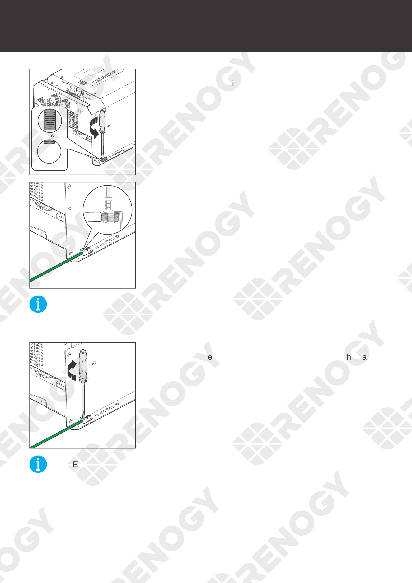
1. Turn the cable retainer screws for the Chassis Ground Lug
counterclockwise with a slotted screwdriver to ensure that
the cable retainer is open.
2. Insert one end of the bare wire into the wiring hole of the
Chassis Ground Lug.
NOT
E
z
Strip some insulation off the grounding cable by using a wire stripper according to the depth
of the wiring hole.
PROT
please read the instructions carefully
Before working on this product.
High voltage,in order to avoid risks,
3. Tighten the cable retainer screws for the Chassis Ground
Lug clockwise with a slotted screwdriver to fasten the cable.
NOT
E
z
The torque of the cable retainer screw is 13.5 N·m. Do not overtighten it to prevent damage.
26
Ground Cable Wiring
AC / INV
CHC
FAULT
Pure Sine Wave Inverter Charger
REMOTE
DRY
CAN
NO
NC
C
CONTACT
CHARCER W
PROT
WARNING
please read the instructions carefully
Before working on this product.
High voltage,in order to avoid risks,
L
L
N
OUTPUT
INPUT
N
NEGATIVE
WARNING
please read the instructions carefully
Before working on this product.
High voltage,in order to avoid risks,
OFF
ON
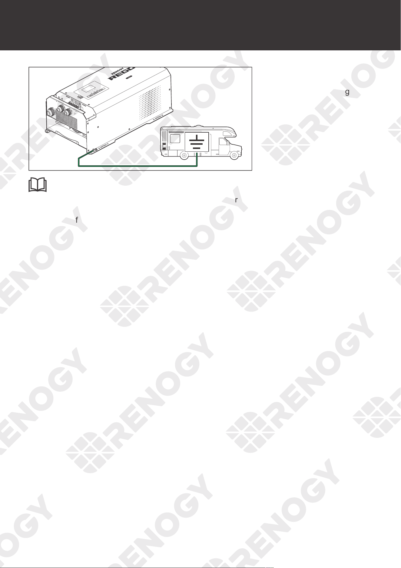
4. Connect the other end
of the bare cable to the
Chassis Ground Lug of the
RV.
INFO
z
When connecting the inverter charger to the chassis ground lug of your RV, consult the
RV supplier to confirm the location of the chassis ground lug. A connection terminal can be
installed if needed.
27
Remote Control Wiring
Remote Control Wiring
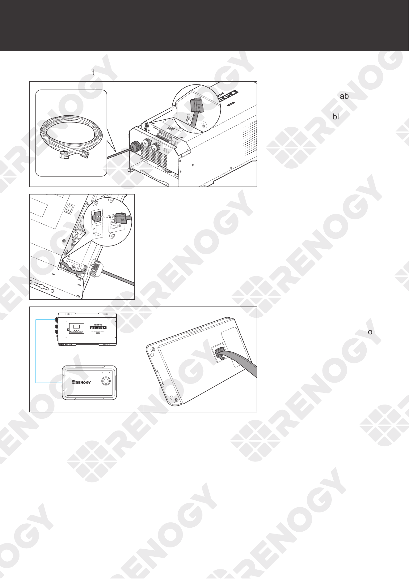
You may choose to use the wired remote control of the inverter charger.
AC / INV
CHC
FAULT
Pure Sine Wave Inverter Charger
REMOTE
DRY
CAN
NO
NC
C
CONTACT
CHARCER W
PROT
WARNING
please read the instructions carefully
Before working on this product.
High voltage,in order to avoid risks,
L
L
N
OUTPUT
INPUT
N
NEGATIVE
WARNING
please read the instructions carefully
Before working on this product.
High voltage,in order to avoid risks,
REMOTE
DRY
CAN
NO
NC
C
CONTACT
L
OUTPUT
OFF
ON
1. Run one end of the
included RJ11 cable
through the Remote &
Accessory Cable Entry.
AC/INV
ON
OFF
CHG
FAULT
WARNING
please read the instructions carefully
Before working on this product.
High voltage,in order to avoid risks,
WARNING
please read the instructions carefully
Before working on this
product.
High voltage,in
order to avoid risks,
INVERTER OUTPUT
NO
NC
C
DRY
CONTACT
BTS
CAN
REMOTE
DRY
CONTACT
NC
C
NO
2. Connect the connector to the Wired Remote Port (REMOTE).
ON
OFF
AC/INV CHG FAULT
Wired Remote Port (REMOTE)
Wired Remote Control
ON ERR
RMS-P2
3. Connect the connector on
the other end of the RJ11
cable to the Wired Remote
Control.
28
Temperature Sensor Wiring
Temperature Sensor Wiring
The temperature sensor measures the temperature of the battery and provides the inverter
charger with a charge voltage calibration mechanism to ensure that the inverter charger can
properly charge the battery within the operating temperature from -4
°
F to 140
°
F or -20
°C
to
60
°C
.
NOT
E
z
Do not use the temperature sensor on a LiFePO4 (LFP) battery which comes with a battery
management system (BMS).
z
There is no requirement on polarity for temperature sensor cables.
OFF
ON
AC / INV
CHC
FAULT
Pure Sine Wave Inverter Charger
REMOTE
DRY
CAN
NO
NC
C
CONTACT
CHARCER W
PROT
WARNING
please read the instructions carefully
Before working on this product.
High voltage,in order to avoid risks,
L
L
N
OUTPUT
INPUT
N
NEGATIVE
WARNING
please read the instructions carefully
Before working on this product.
High voltage,in order to avoid risks,
REMOTE
DRY
CAN
CONTACT
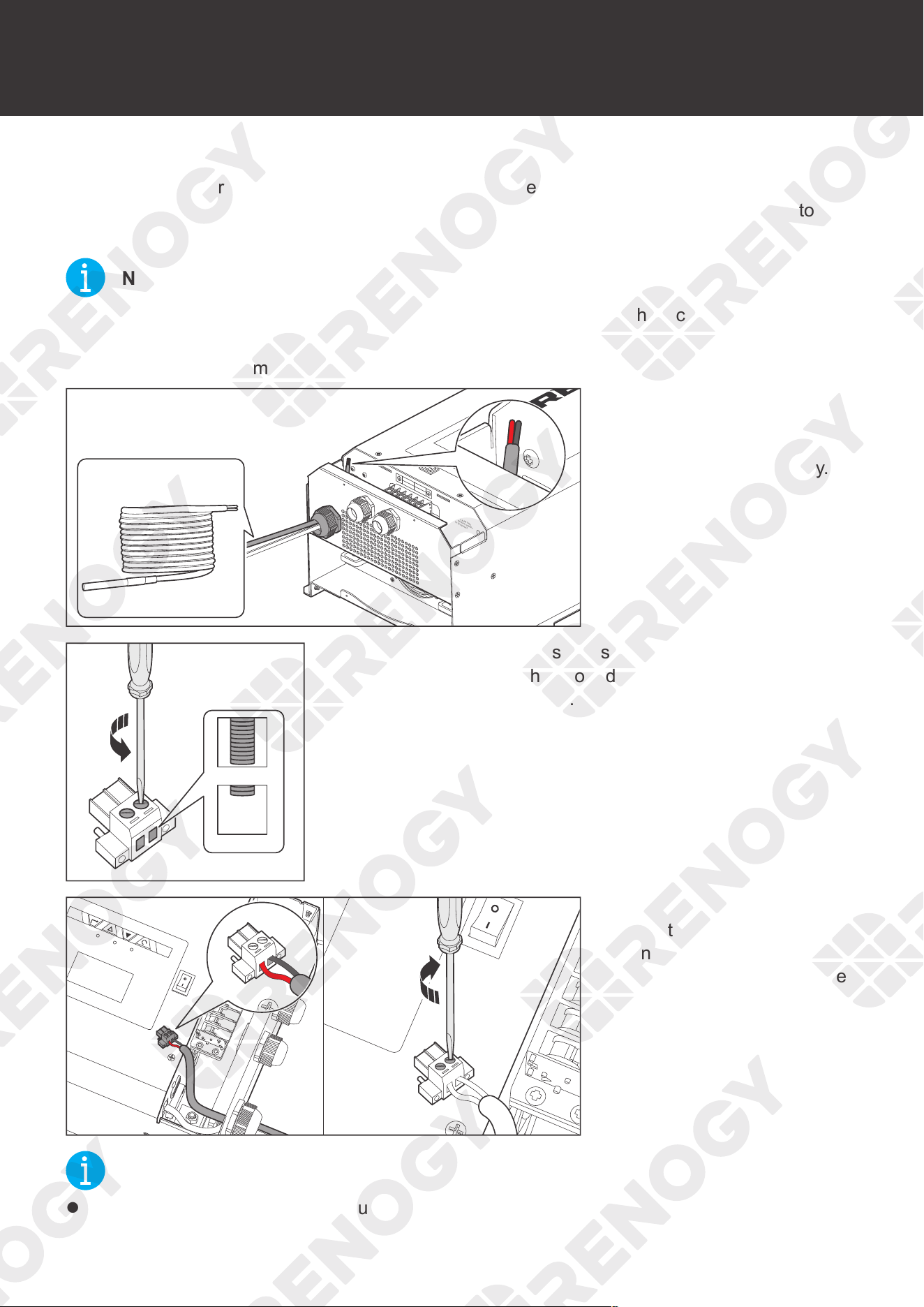
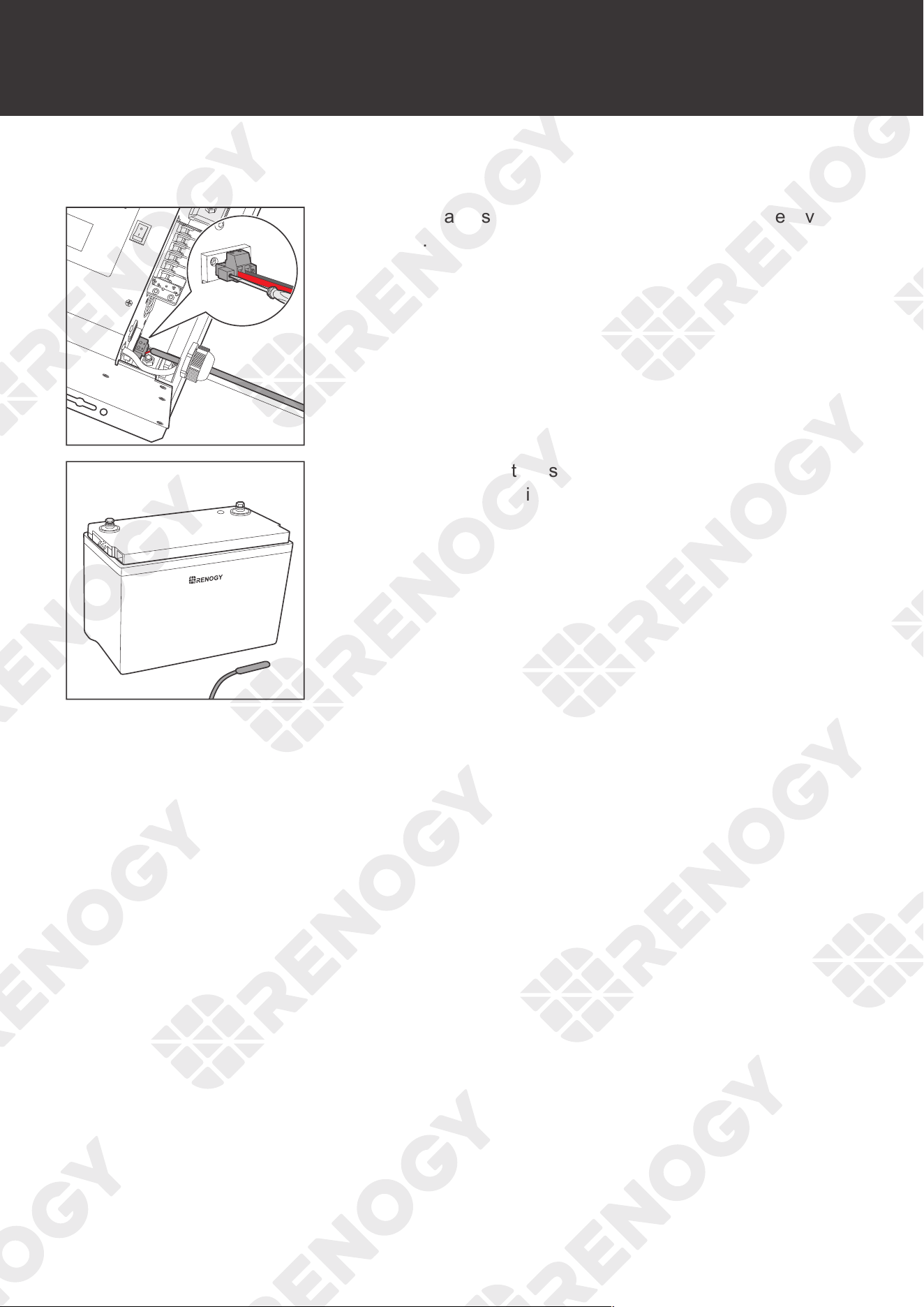
1. Run the bare terminal of
the temperature sensor
through the Remote &
Accessory Cable Entry.
Open
Close
2. Turn the cable retainer screws for wire harness connector
counterclockwise with a slotted screwdriver to ensure that
the cable retainer is open.
AC/INV
ON
OFF
CHG
FAULT
WARN ING
please read the instructions carefully
Before working on this product.
High voltage,in order to avoid risks,
WARN ING
please read the instructions carefully
Before working on this product.
High voltage,in order to avoid risks,
CHARGER INPUT
PROTECT
INVERTER OUTPUT
PROTECT
NO
NC
C
DRY
CONTACT
ON
OFF
NO
NC
C
DRY
CONTACT
3. Insert the bare terminal of
the temperature sensor
into the harness connector
and tighten it with a slotted
screwdriver by turning the
cable retainer screw for
wire harness connector
clockwise.
NOT
E
z
Strip some insulation off the grounding cable with a wire stripper.
29
Temperature Sensor Wiring
z
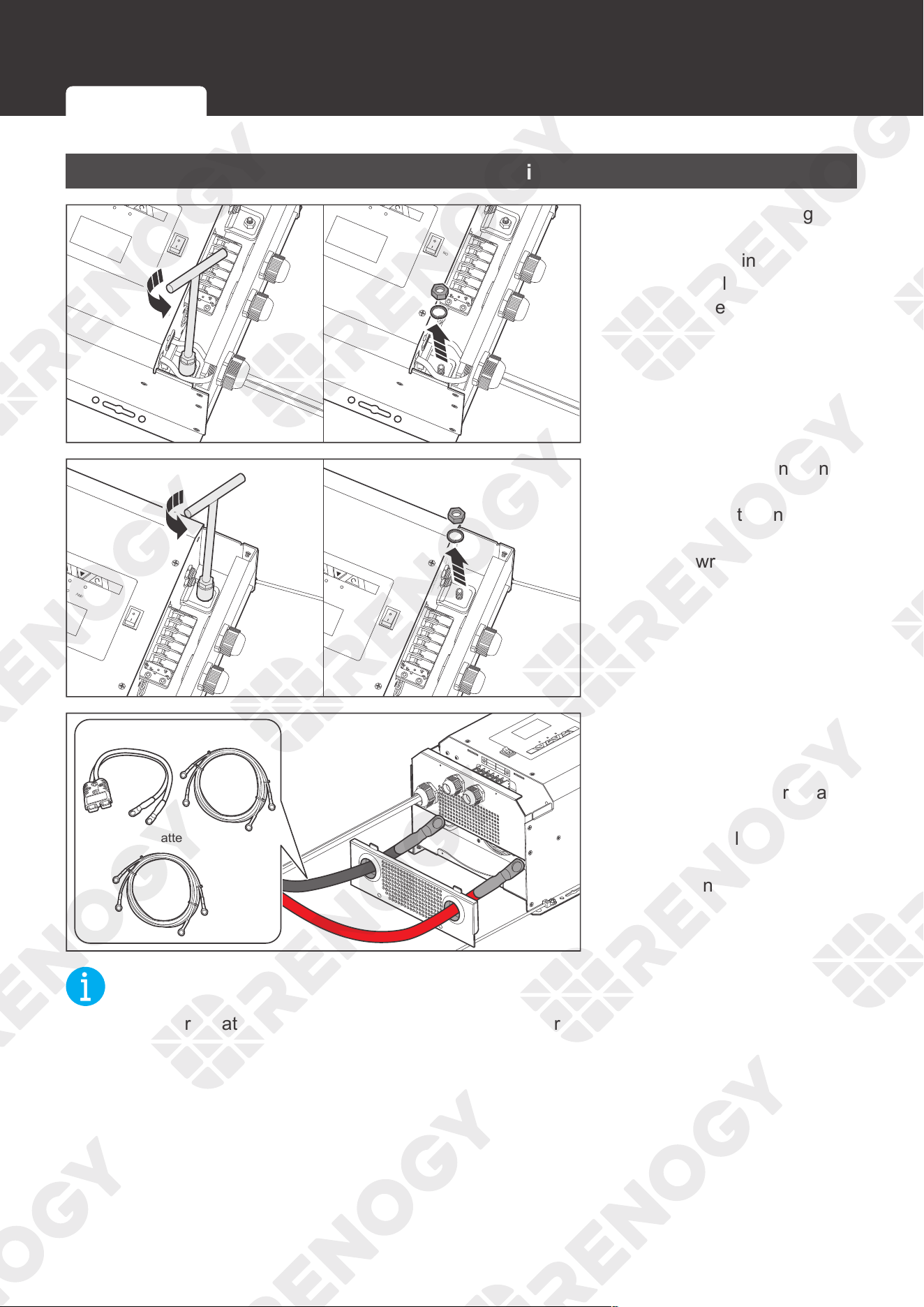
Do not overtighten the cable retainer screws. Otherwise it will lead to stripped screws or
screw bending.
AC
/INV
ON
OFF
CHG
please read the instructions carefully
Before working on this product.
WARNI NG
please read the instructions carefully
Before working on this product.
High volt
age,in order to avoid risks,
NO
NC
C
DRY
CONTACT
BTS
CAN
NO
4. Plug the harness connector into the BTS Port of the inverter
charger.
+
-
5. Place the temperature sensor near the battery and fix it with
a cable tie or insulation tape if necessary.
30
Battery Wiring
Battery Wiring
Device-side Wiring
AC/INV
ON
OFF
CHG
FAULT
WA
RNING
please r
ead the instructions carefully
Before wor
king on this product.
High voltage,in order to avoid risks,
WARNI NG
please read the instructions ca
refully
Before working on this product.
High voltage,in order to av
oid risks,
CHARGER INPUT
PROTECT
INVERTER OUTPUT
PROTECT
NO
NC
C
DRY
CONTACT
AC/INV
ON
OFF
CHG
FAULT
WARNI NG
please read the instructions carefully
Bef
ore working on this product.
High voltage,in order to avoid risks,
WARNI NG
please read the instruct
ions carefully
Before working on this product.
High voltage,in order
to avoid risks,
CHARGER INPUT
PROTECT
INVERTER OUTPUT
PROTECT
NO
NC
C
DRY
CONTACT
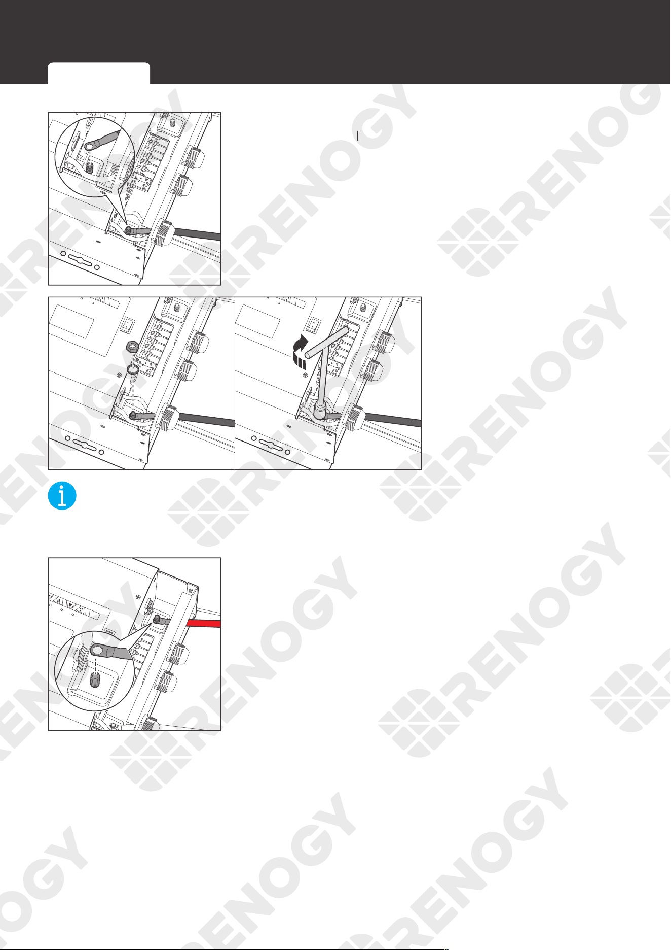
1. Remove the retaining
nut of the DC Negative
Battery Terminal by turning
it counterclockwise with a
socket wrench and then
remove the gasket.
AC/INV
ON
OFF
CHG
FAULT
WARNI NG
please read the instructions carefully
Before working on this product.
High voltage,in order to avoid risks,
WARNI NG
please read the instructions carefully
Before working on this product.
High voltage,in order to avoid risks,
CHARGER INPUT
PROTECT
INVERTER OUTPUT
PROTECT
NC
C
AC/INV
ON
OFF
CHG
WARNI NG
please read the instructions carefully
Before working on this product.
High voltage,in order to avoid risks,
WARNI NG
please read the instructions carefully
Before working on this product.
High voltage,in order to avoid risks,
CHARGER INPUT
PROTECT
INVERTER OUTPUT
PROTECT
NC
C
2. Remove the retaining nut
of the DC Positive Battery
Terminal by turning it
counterclockwise with a
socket wrench and then
remove the gasket.
AC / INV
CHC
FAULT
REMOTE
DRY
CAN
NO
NC
C
CONTACT
CHARCER W
PROT
WARNING
please read the instructions carefully
Before working on this product.
High voltage,in order to avoid risks,
L
L
N
OUTPUT
INPUT
N
NEGATIVE
WARNING
please read the instructions carefully
Before working on this product.
High voltage,in order to avoid risks,
REGO Battery Kit
Normal Battery Kit
OFF
ON
3. Insert the positive ring
terminal of the battery
adapter cable through the
DC Positive Battery Cable
Entry, and the negative
ring terminal through
the DC Negative Battery
Cable Entry.
NOT
E
z
Select appropriate battery adapter cables based on your needs.
Device-side Wiring Battery-side Wiring
31
Battery Wiring
AC/INV
ON
OFF
CHG
FAULT
WARNI NG
please read the instructions carefully
Before working on this product.
High voltage,in order to avoid risks,
WARNI NG
please read the instructions carefully
Before working on this product.
High voltage,in order to avoid risks,
CHARGER INPUT
PROTECT
INVERTER OUTPUT
PROTECT
NO
NC
C
DRY
CONTACT
NO
NC
C
DRY
CONTACT
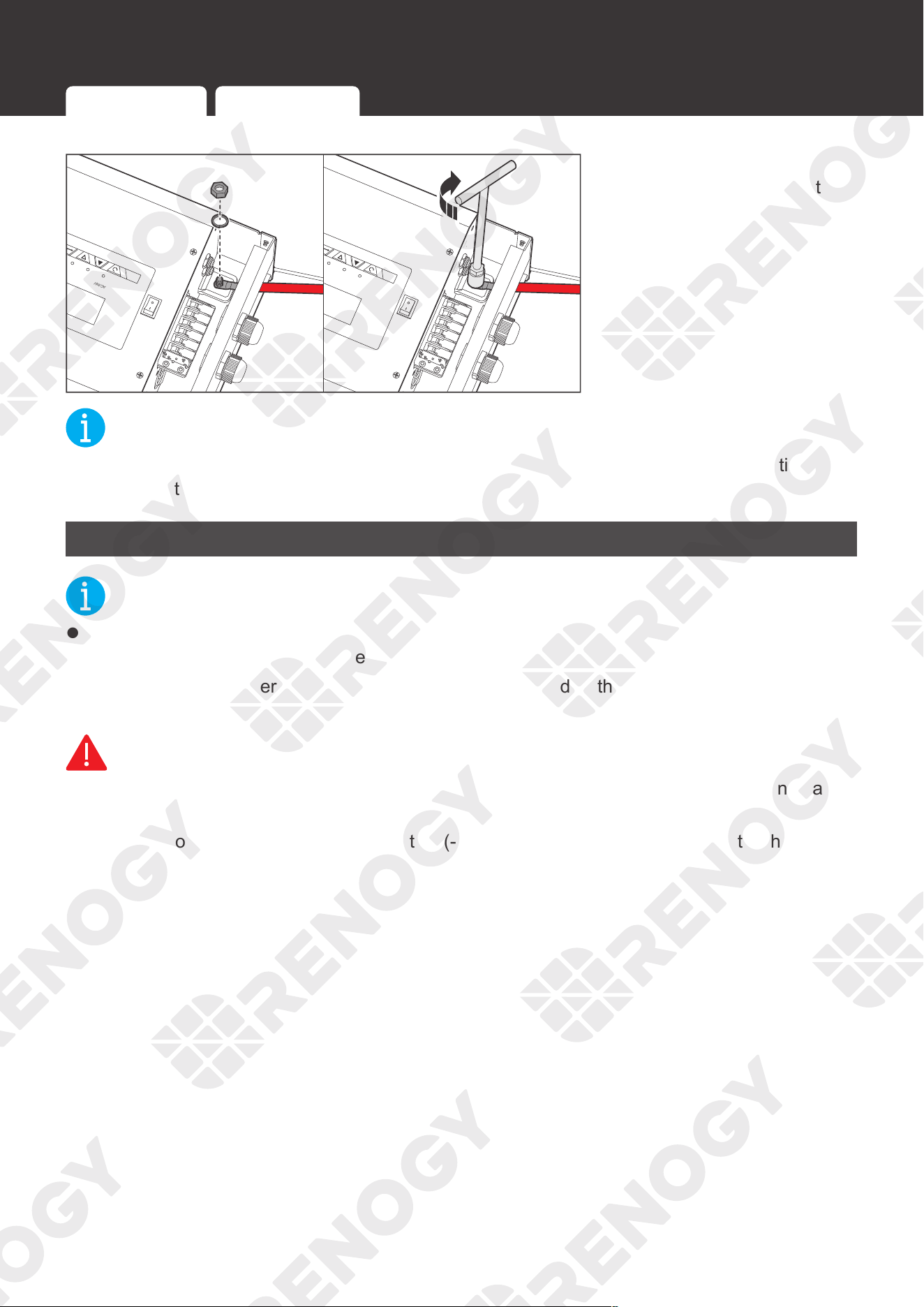
4. Connect the negative ring terminal to the DC Negative
Battery Terminal.
AC/INV
ON
OFF
CHG
FAULT
WARNI NG
please read the instructions carefully
Before working on this product.
High voltage,in order to avoid risks,
WARNI NG
please read the instructions carefully
Before working on this product.
High voltage,in order to avoid risks,
CHARGER INPUT
PROTECT
INVERTER OUTPUT
PROTECT
NO
NC
C
DRY
CONTACT
AC/INV
ON
OFF
CHG
FAULT
WARNI NG
please read the instructions carefully
Before working on this product.
High voltage,in order to avoid risks,
WARNI NG
please read the instructions carefully
Before working on this product.
High voltage,in order to avoid risks,
CHARGER INPUT
PROTECT
INVERTER OUTPUT
PROTECT
NO
NC
C
DRY
CONTACT
5. Install the gasket and the
retaining nut, and tighten
the nut clockwise with a
socket wrench.
NOT
E
z
The retaining nut torque of the DC Negative Battery Terminal is 26 N·m. Do not overtighten it
to prevent damage.
AC/INV
ON
OFF
CHG
FAULT
WARNI NG
please read the instructions carefully
Before working on this product.
High voltage,in order to avoid risks,
WARNI NG
please read the instructions carefully
Before working on this product.
High voltage,in order to avoid risks,
CHARGER INPUT
PROTECT
INVERTER OUTPUT
PROTECT
NO
NC
C
DRY
CONTACT
WARNING
please read the instructions carefully
Before working on this product.
High voltage,in order to avoid risks,
WARNING
please read the instructions carefully
Before working on this product.
High voltage,in order to avoid risks,
CHARGER INPUT
PROTECT
INVERTER OUTPUT
PROTECT
6. Connect the positive ring terminal to the DC Positive Battery
Cable Entry.
Device-side Wiring Battery-side Wiring
32
Battery Wiring
AC/INV
ON
OFF
CHG
FAULT
WARNI NG
please read the instructions carefully
Before working on this product.
High voltage,in order to avoid risks,
WARNI NG
please read the instructions carefully
Before working on this product.
High voltage,in order to avoid risks,
CHARGER INPUT
PROTECT
INVERTER OUTPUT
PROTECT
NO
NC
C
DRY
CONTACT
AC/INV
ON
OFF
CHG
FAULT
WARNI NG
please read the instructions carefully
Before working on this product.
High voltage,in order to avoid risks,
WARNI NG
please read the instructions carefully
Before working on this product.
High voltage,in order to avoid risks,
CHARGER INPUT
PROTECT
INVERTER OUTPUT
PROTECT
NO
NC
C
DRY
CONTACT
7. Install the gasket and
retaining nut, and tighten
the nut clockwise
with a socket wrench.
NOT
E
z
The retaining nut torque of the DC Positive Battery Terminal is 26 N·m. Do not overtighten it
to prevent damage.
Battery-side Wiring
NOT
E
z
Identify the polarities (positive and negative) on the cables used for the batteries. A reverse
polarity contact may damage the inverter charger.
z
Ensure that the Anderson connectors are fully seated and/or the ring terminals are securely
connected.
WARNIN
G
z
Do not touch the positive and negative terminals of the battery directly with your hands at
the same time.
z
Do not allow the positive (+) and negative (-) terminals of the battery to contact with each
other.
Device-side Wiring Battery-side Wiring
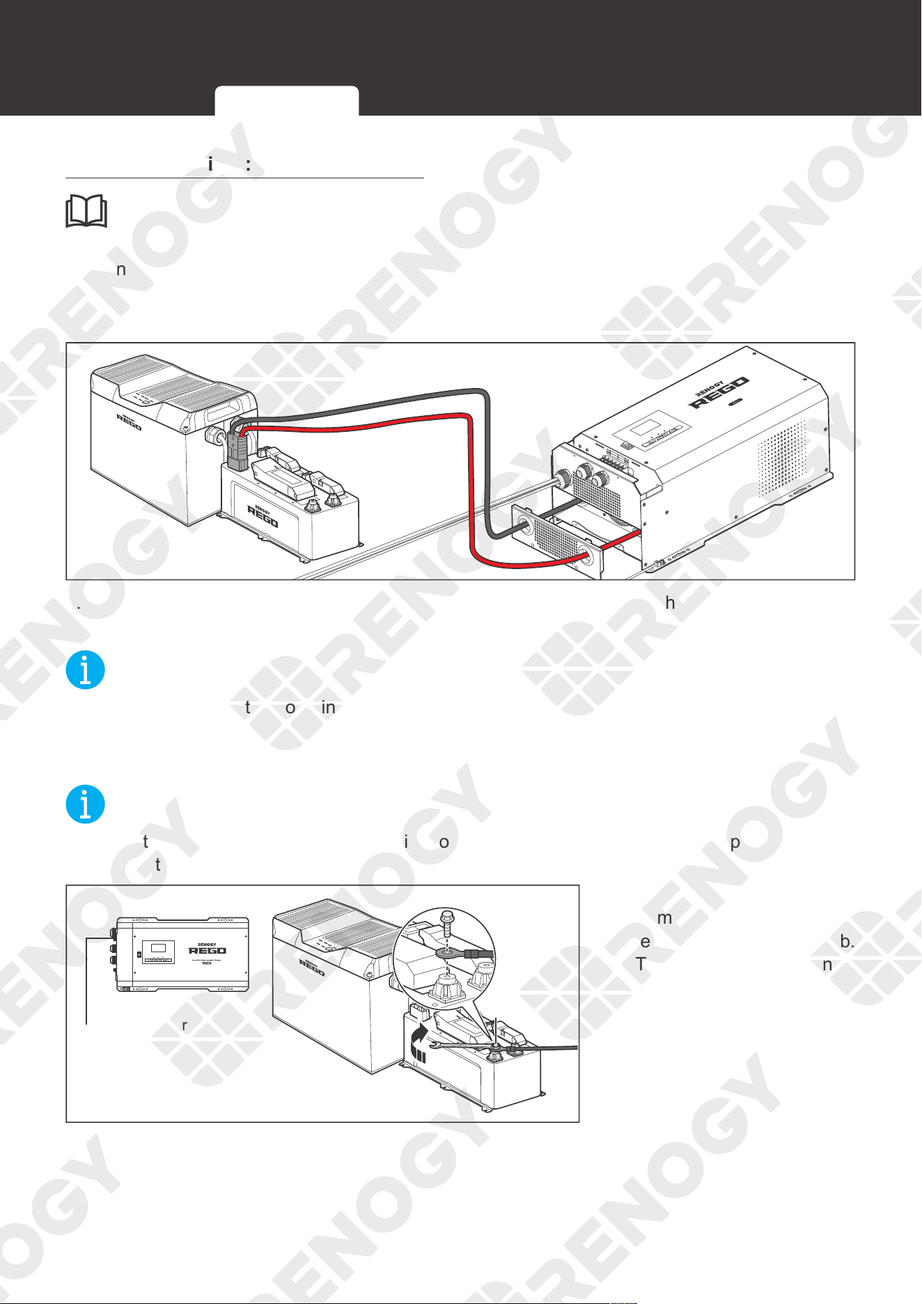
33
Battery Wiring
Battery Scenario A: REGO Battery Kit
INF
O
z
Read the REGO 4 Ports 400A System Combiner Box User Manual carefully before
connection.
█
Using Battery Adapter Cable (Anderson 350 Connector to Ring Terminal Adapter
Cable)
AC / INV
CHC
FAULT
Pure Sine Wave Inverter Charger
REMOTE
DRY
CAN
NO
NC
C
CONTACT
CHARCER W
PROT
WARNING
please read the instructions carefully
Before working on this product.
High voltage,in order to avoid risks,
L
L
N
OUTPUT
INPUT
N
NEGATIVE
WARNING
please read the instructions carefully
Before working on this product.
High voltage,in order to avoid risks,
OFF
ON
1. Connect the Anderson 350 connector of the battery adapter cable to the System Combiner
Box.
NOT
E
z
When connecting the combiner box to the inverter charger via the system hub of Anderson
connector, install a 400A NH fuse in the top disconnection switch.
█
Using Battery Adapter Cable (Ring Terminal Adapter Cable)
NOT
E
z
Select the appropriate wrench according to positive/negative wire fixing bolt specifications of
the system hub.
-
ON
OFF
AC/INV CHG FAULT
DC Negative
Battery Terminal
1. Connect the negative ring
terminal to the negative
terminal of the system hub.
Tighten the wire retaining
bolt with a wrench.
Device-side Wiring Battery-side Wiring
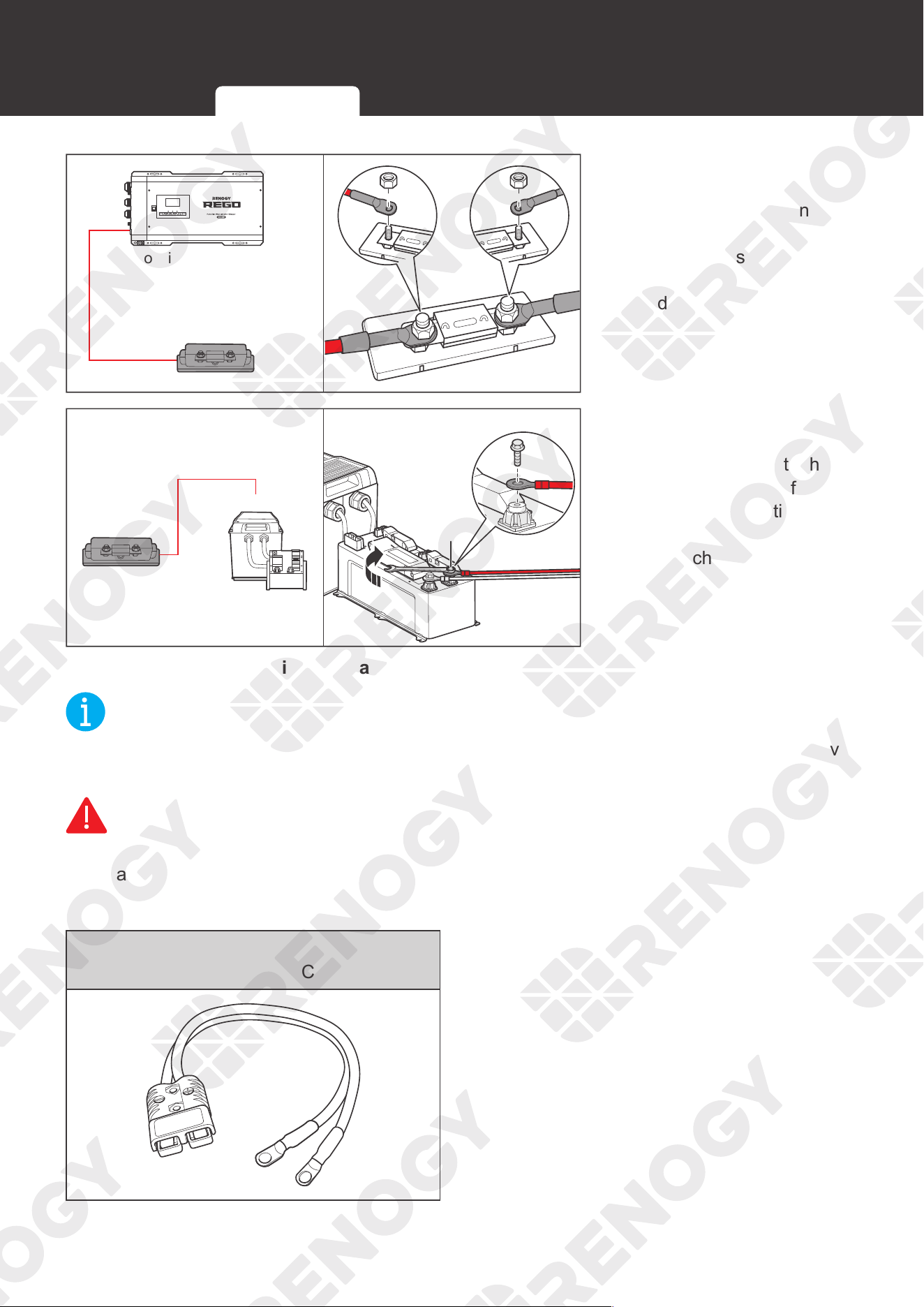
34
Battery Wiring
ON
OFF
AC/INV CHG FAULT
DC Positive Battery Terminal
2. For your safety, it is
recommended to use a
DC fuse (400A). Connect
the positive ring terminal
to the DC fuse. Install the
fuse cable on the other
end of the fuse.
+
+
3. Attach the other ring
terminal of the other
end of fuse cable to the
poisitive terminal of the
system hub and tighten
the wire retaining bolt with
a wrench.
█
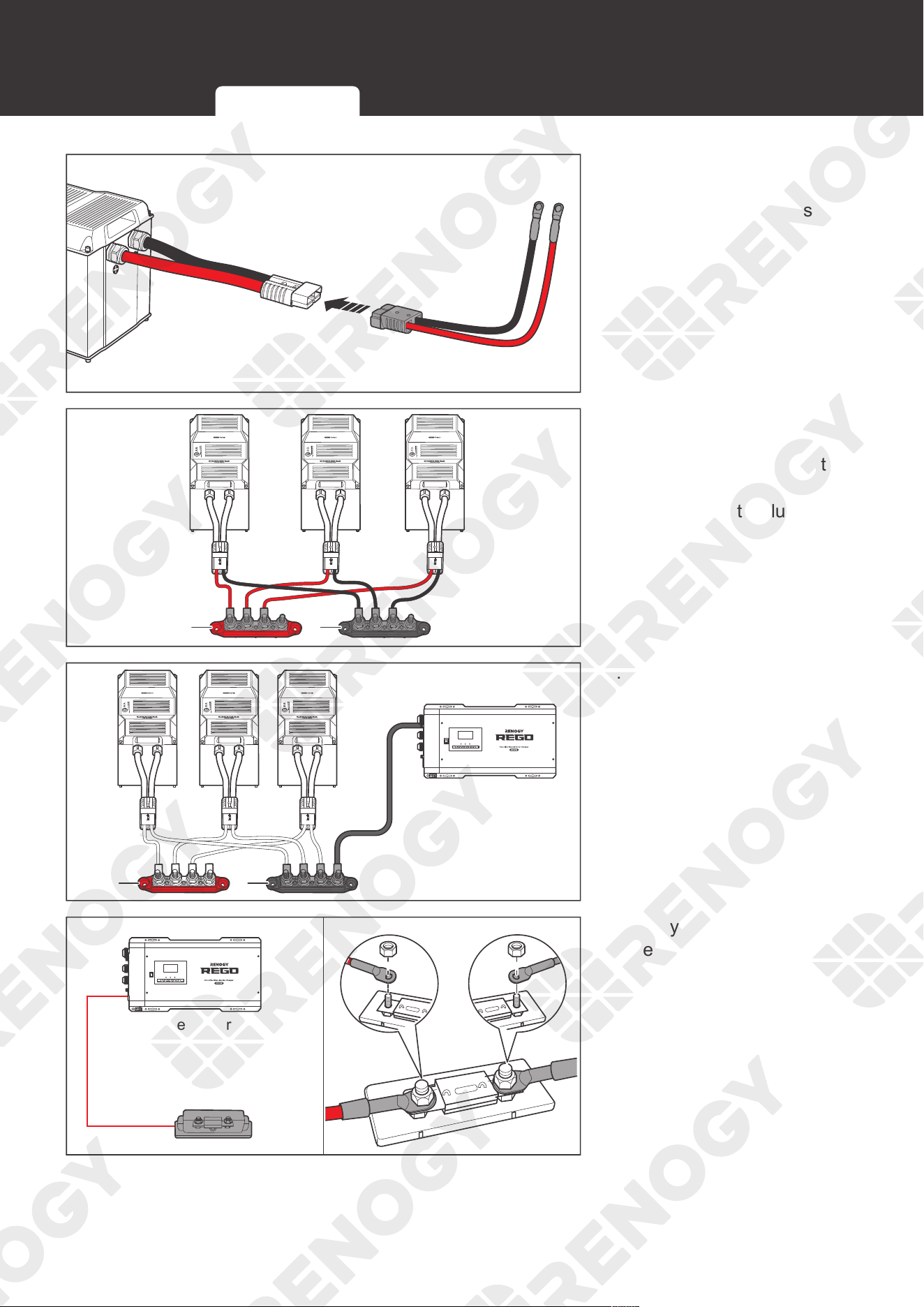
Using Positive/Negative Busbars Accessory Set
NOT
E
z
Select the applicable wrench according to wire fixing bolt specifications of Positive/Negative
Busbars.
WARNIN
G
z
Select the right size of positive/negative sink according to the maximum continuous
charging/discharging current of the battery operation.
Essential Accessories
Gray Anderson 350 Connector to Ring
Terminal Adapter Cable
Device-side Wiring Battery-side Wiring
35
Battery Wiring
1. Connect the Anderson
Connectors of the batteries
to the Adapter Cables (sold
separately).
+
-
2. Connect the positive and
negative ring terminals
of the Adapter Cables to
the Positive and Negative
Busbars (not included)
respectively.
-
+
DC Negative
Battery Terminal
ON
OFF
AC/INV CHG FAULT
3. Attach the negative ring
terminal to the Negative
Busbar and tighten the
wire retaining bolt with a
wrench.
ON
OFF
AC/INV CHG FAULT
DC Positive Battery Terminal
4. For your safety, it is
recommended to use a
DC fuse (400A). Connect
the positive ring terminal
to the DC fuse. Install the
fuse wire on the other end
of the fuse.
Device-side Wiring Battery-side Wiring
36
Battery Wiring
-
DC Positive
Battery Terminal
+
ON
OFF
AC/INV CHG FAULT
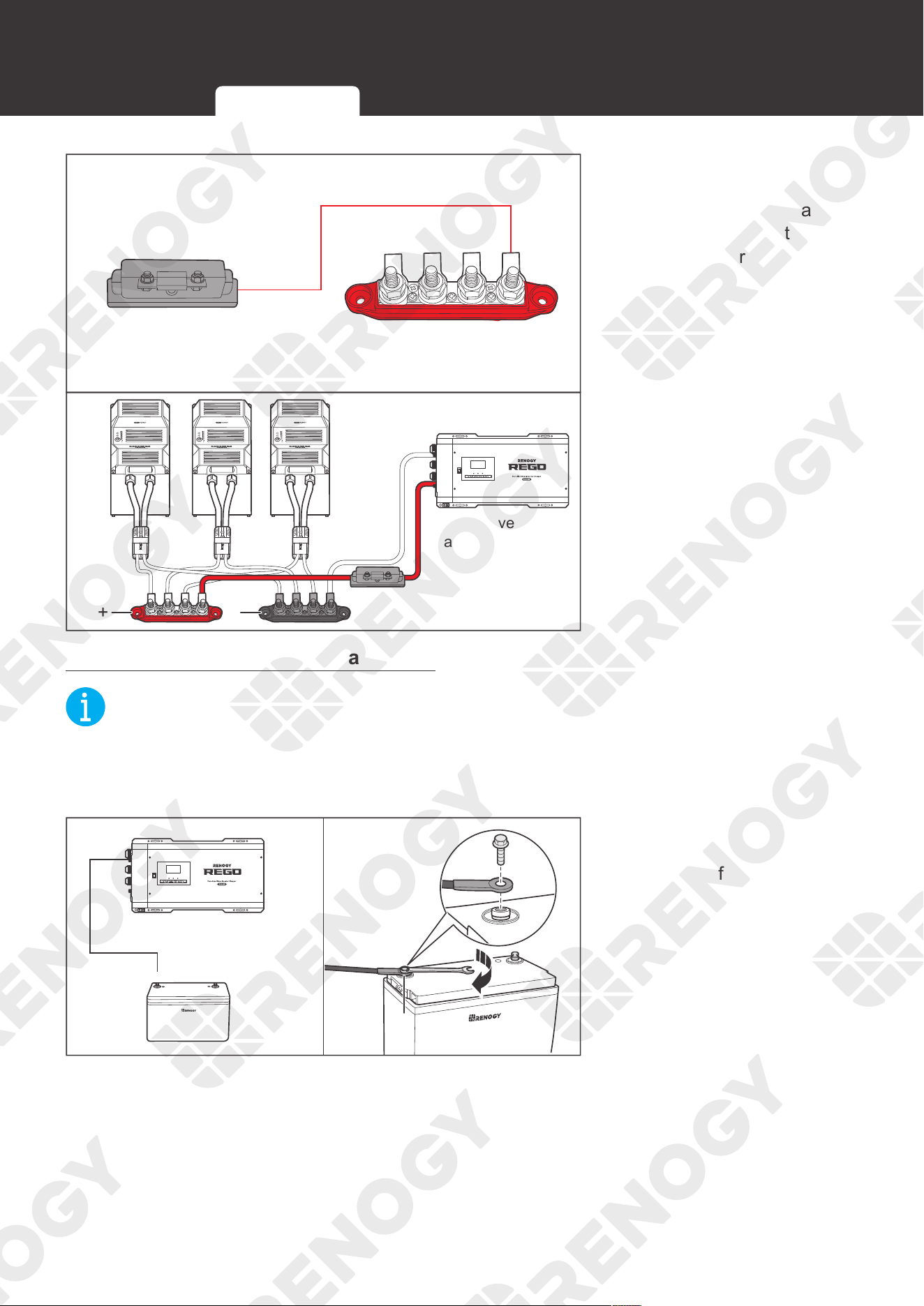
5. Attach the ring terminal of
the other end of fuse cable
to the Positive Busbar and
tighten the wire retaining
bolt with a wrench.
Battery Scenario B: Normal Battery Kit
NOT
E
z
Select the appropriate wrench according to the specification of the positive/negative wire
retaining bolt of the system hub.
z
Ensure that the ring terminals are securely connected.
+
-
12
12
-
-
ON
OFF
AC/INV CHG FAULT
DC Negative Battery Terminal
+
-
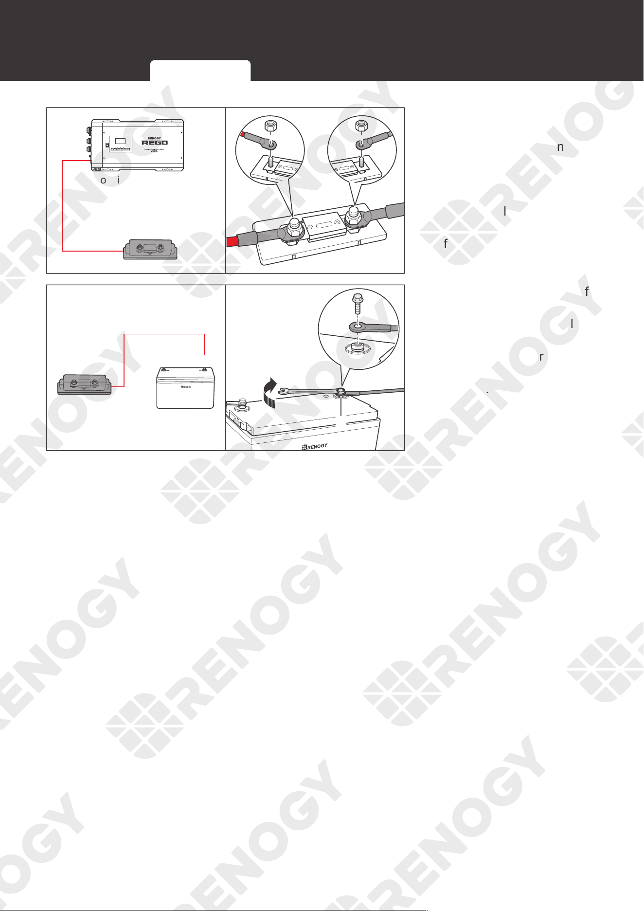
1. Connect the negative ring
terminal to the negative
terminal of a Normal
Battery. Tighten the
wire retaining bolt with a
wrench.
Device-side Wiring Battery-side Wiring
37
Battery Wiring
ON
OFF
AC/INV CHG FAULT
DC Positive Battery Terminal
2. For your safety, it is
recommended to use a
DC fuse (400A). Connect
the positive ring terminal
of the inverter charger
adapter cable to the DC
fuse. Install the fuse wire
on the other end of the
fuse.
+
-
+
+
+
+
3. The other ring terminal of
the fuse wire is connected
to the positive terminal
of the Normal Battery.
Tighten the wire retaining
bolt clockwise with a
wrench.
Device-side Wiring Battery-side Wiring
38
AC Output Wiring
AC Output Wiring
Device-side Wiring
AC / INV
CHC
OFF
ON
FAULT
REMOTE
DRY
CAN
NO
NC
C
CONTACT
CHARCER W
PROT
WARNING
please read the instructions carefully
Before working on this product.
High voltage,in order to avoid risks,
L
L
N
OUTPUT
INPUT
N
NEGATIVE
WARNING
please read the instructions carefully
Before working on this product.
High voltage,in order to avoid risks,
OFF
ON
REMOTE
DRY
CAN
NO
NC
C
CONTACT
L
L
N
OUTPUT
INPUT
N
NEGATIVE
WARNING
please read the instructions carefully
Before working on this product.
High voltage,in order to avoid risks,
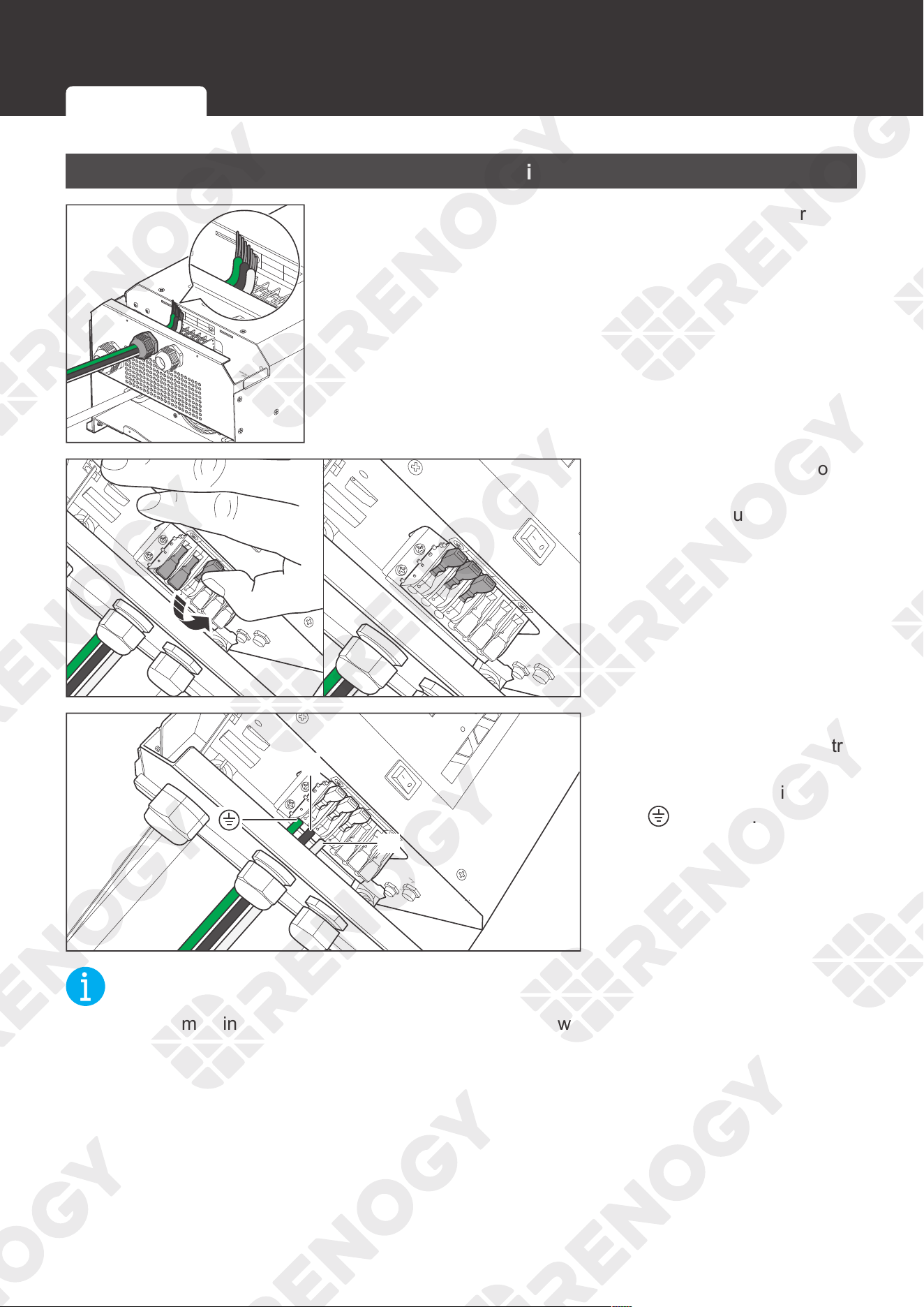
1. Run three bare wires through the AC Output Lever Terminal
Block.
INPUT
N
L
OUTPUT
L
N
ON
DRY CONTACT
NC
C
BTS
CHARGER INPUT
PROTECT
INVERTER OUTPUT
PROTECT
ON
OFF
INPUT
N
L
OUTPUT
L
N
ON
DRY CONTACT
NC
C
BTS
CHARGER INPUT
PROTECT
INVERTER OUTPUT
PROTECT
ON
OFF
2. Push up the switches of
the wire harness retainer
of the AC Output Lever
Terminal Block.
INPUT
N
L
OUTPUT
L
N
ON
DRY CONTACT
NC
C
BTS
CHARGER INPUT
PROTECT
INVERTER OUTPUT
PROTECT
AC/INV
L
N
ON
OFF
3. Connect the live wire to
the (L) terminal, the neutral
wire to the (N) terminal,
and the ground wire to the
(
) terminal.
NOT
E
z
Strip 10 mm of insulation off the AC Output cable with a wire stripper.
Device-side Wiring Load Wiring
39
AC Output Wiring
ON
DRY CONTACT
NC
C
AC/INV
CHG
CHARGER INPUT
PROTECT
BTS
INPUT
N
L
OUTPUT
L
N
INVERTER OUTPUT
PROTECT
CAN
REMOTE
ON
OFF
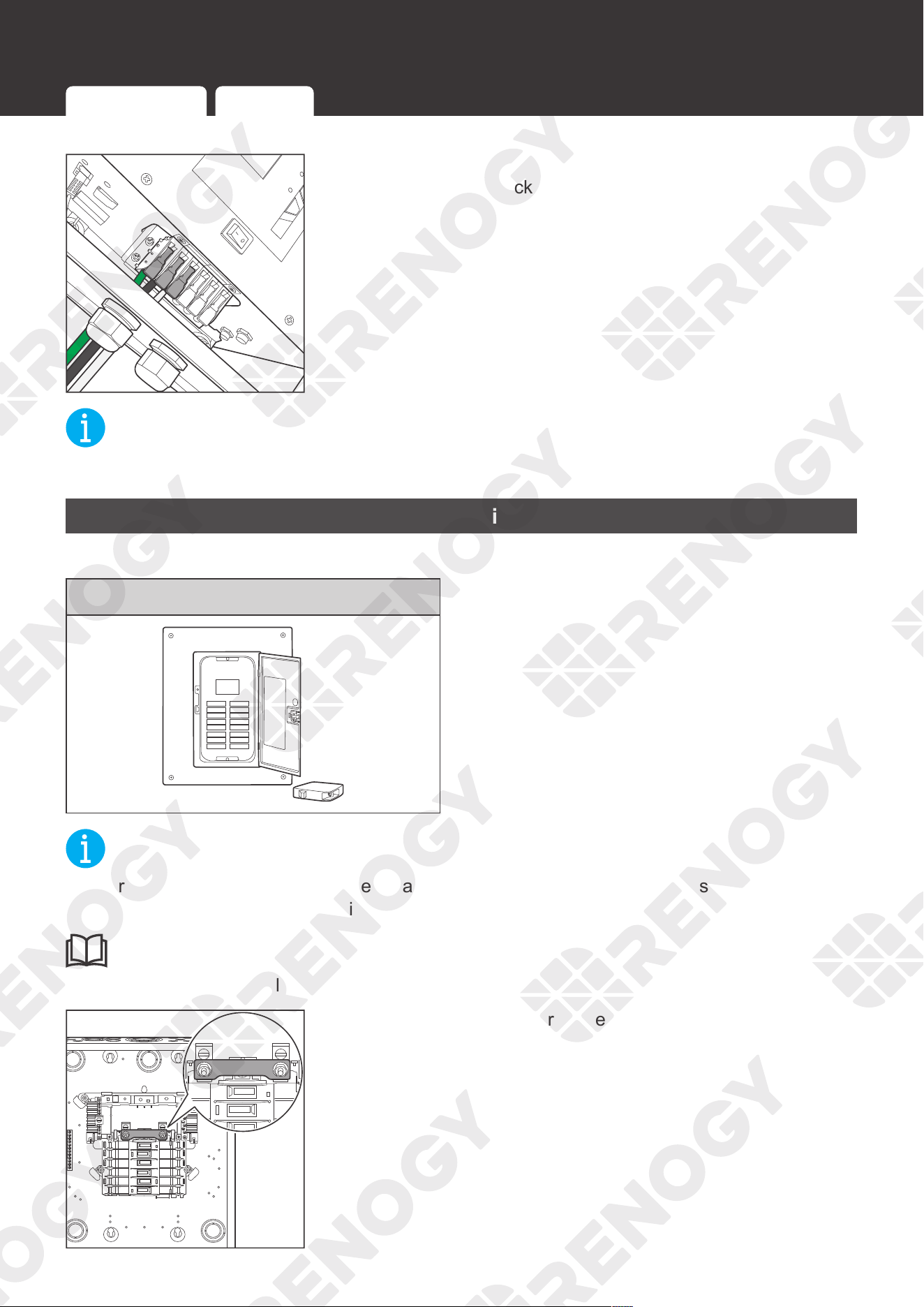
4. Press down the wire harness retainer of the AC Output
Lever Terminal Block.
NOT
E
z
Tug at the wire to ensure a firm connection.
Load Wiring
Recommended Accessories
AC Load Center
NOT
E
z
For your safety, it is recommended that qualified electricians familiar with safety codes of
electrical systems perform the installation.
INF
O
z
Read the user manual of the AC load center carefully before installation.
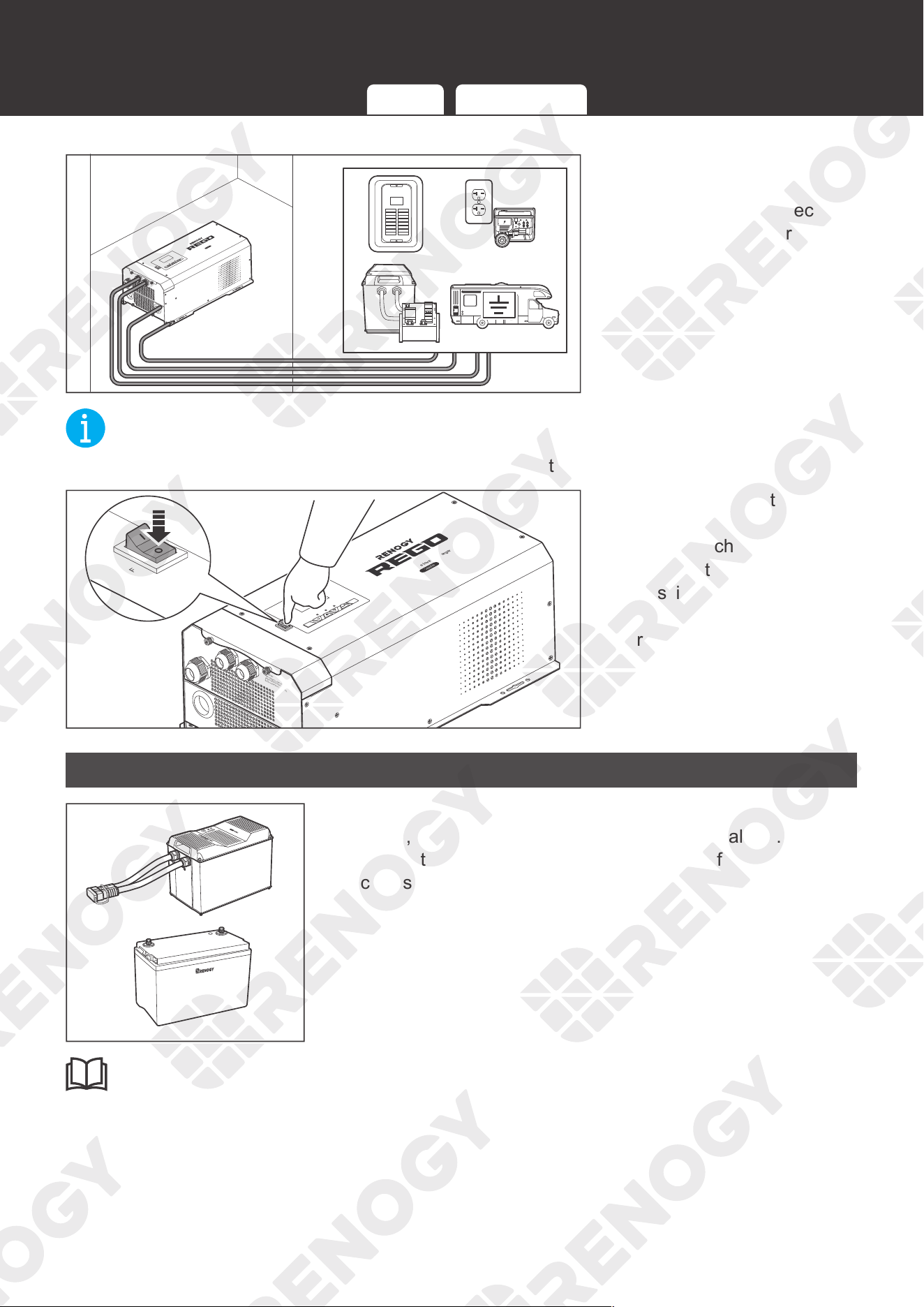
1. Remove the front cover of the AC load center and connect
the two live wire busbars with a copper strip.
Device-side Wiring Load Wiring
40
AC Output Wiring
AC / INV
CHC
FAULT
Pure Sine Wave Inverter Charger
REMOTE
DRY
CAN
NO
NC
C
CONTACT
CHARCER W
PROT
WARNING
please read the instructions carefully
Before working on this product.
High voltage,in order to avoid risks,
L
L
N
OUTPUT
INPUT
N
NEGATIVE
WARNING
please read the instructions carefully
Before working on this product.
High voltage,in order to avoid risks,
PE
N
N
L
OFF
ON
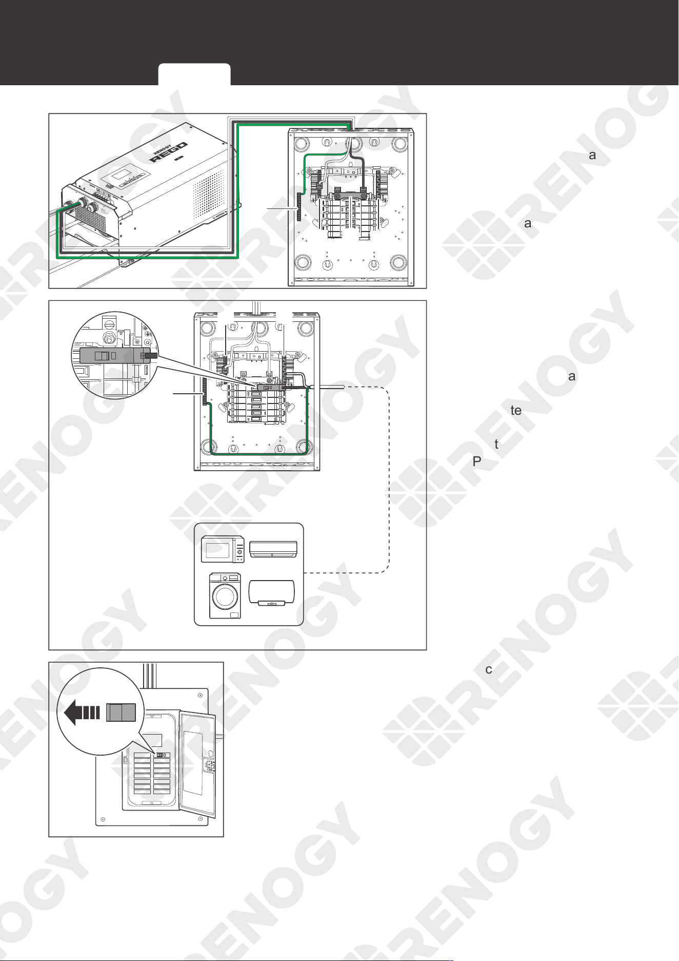
2. Connect the AC Output
cable of the inverter
charger to the AC load
center. Connect the live
wire to the (L) terminal,
the neutral wire to the (N)
terminal, and the ground
wire to the (PE) busbar.
N N
PE
I/ON
O/OFF
I/ON
O/OFF
3. Select an appropriate
circuit breaker according
to the operating load
current, and connect the
load to the AC load center.
Connect the live wire to
the (L) terminal, the neutral
wire to the (N) terminal,
and the ground wire to the
(PE) busbar.
I/ON
O/OFF
I/ON
O/OFF
4. Install the front cover of the AC load center and turn on all
the circuit breakers in the AC load center.
Device-side Wiring Load Wiring
41
AC Input Wiring
AC Input Wiring
The AC input is optionally installed on demand.
AC / INV
CHC
OFF
ON
FAULT
REMOTE
DRY
CAN
NO
NC
C
CONTACT
CHARCER W
PROT
WARNING
please read the instructions carefully
Before working on this product.
High voltage,in order to avoid risks,
L
L
N
OUTPUT
INPUT
N
NEGATIVE
WARNING
please read the instructions carefully
Before working on this product.
High voltage,in order to avoid risks,
AC Input Lever Terminal Block
OFF
ON
REMOTE
DRY
CAN
NO
NC
C
CONTACT
L
L
N
OUTPUT
INPUT
N
NEGATIVE
WARNING
please read the instructions carefully
Before working on this product.
High voltage,in order to avoid risks,
ON
OFF
AC/INV CHG FAULT
Shore Power or Generator
(120V Single Phase, 40A Max.)
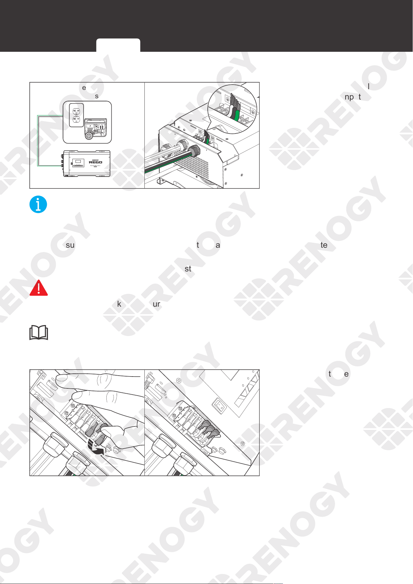
1. Run the AC power cable
through the AC Input
Cable Grommet.
NOT
E
z
The AC Input Cable Grommet has an inner diameter of 13 mm. Properly select the AC cable
size and ensure that three bare wires can run through the grommet at the same time.
z
Make sure the AC input current is no greater than 40A. Otherwise, the inverter charger
cannot work.
z
The size of the AC input cable is at least 8 AWG.
WARNIN
G
z
Risk of electric shock! Make sure the shore power or the generator is disconnected during
AC input wiring.
INFO
z
When connecting the inverter charger to an AC Input, read the user manual of the AC Input
for wiring instructions.
ON
ON
DRY CONTACT
CAN
REMOTE
NC
C
OFF
CHARGER INPUT
PROTECT
BTS
INPUT
N
L
OUTPUT
L
N
INVERTER OUTPUT
PROTECT
INPUT
N
L
OUTPUT
L
N
ON
DRY CONTACT
CAN
REMOTE
NC
C
AC/INV
CHG
CHARGER INPUT
PROTECT
BTS
INVERTER OUTPUT
PROTECT
ON
OFF
2. Push up on the lever of the
AC Input Terminal Block.
Device-side Wiring Load Wiring
42
AC Input Wiring
INPUT
N
L
OUTPUT
L
N
ON
DRY CONTACT
NC
C
CHARGER INPUT
PROTECT
BTS
INVERTER OUTPUT
PROTECT
L
N
ON
OFF
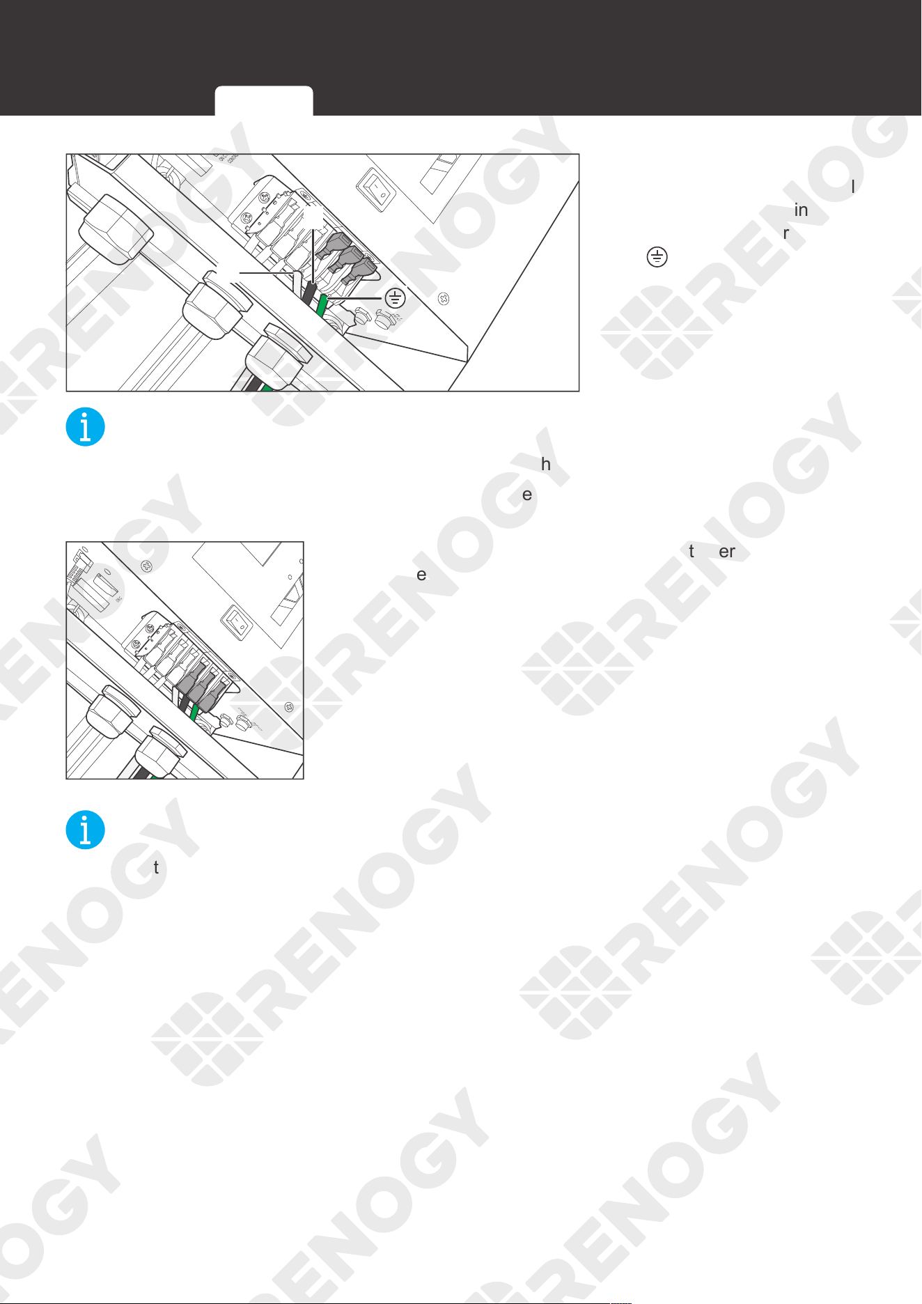
3. Connect the live wire to
the (L) terminal, the neutral
wire to the (N) terminal,
and the ground wire to the
(
) terminal.
NOT
E
z
Strip 10 mm of the insulation off the AC input cable with a wire stripper.
z
You can only connect the AC input to the AC Input Lever Terminal Block. Otherwise the
inverter charger will be damaged.
ON
DRY CONTACT
NC
C
AC/INV
CHG
CHARGER INPUT
PROTECT
BTS
INPUT
N
L
OUTPUT
L
N
INVERTER OUTPUT
PROTECT
CAN
REMOTE
ON
OFF
4. Press down the switch of the harness retainer of the AC
Input Lever Terminal Block.
NOT
E
z
Tug at the wire to ensure a firm connection.
Device-side Wiring Load Wiring
43
Automatic Generator Start
Automatic Generator Start
If the inverter charger is connected to an AC Power Supply (AC Input) and the generator can
automatically start or stop. It is recommended to connect the generator to the Dry Contact Relay
Terminal Block with a signal cable.
When the voltage of the inverter charger is lower than the set voltage in Program 96, the inverter
charger will automatically start the generator and charge the battery while the load is supplied by
the generator. When the voltage of the inverter charger is higher than the set value, the inverter
charger will automatically shut down the generator.
INF
O
z
Read the user manual of the AC Input carefully before connection. Make sure the generator
can automatically start or stop. Identify NC (normally closed contact), NO (normally open
contact), and C (common static contact) of the generator and ensure signal lines are
connected properly.
NOT
E
z
You can set the voltage of the inverter charger in Program 96. The voltage should be set
after the inverter charger is turned on. Finish the installation of the inverter charger first. For
more instructions, read Program Codes in the user manual.
z
Do not store the inverter charger with automatic generator start feature enabled. Generators
exhaust dangerous fumes in operation.
WARNIN
G
z
Risk of electric shock! Make sure the AC Input is turned off during connection.
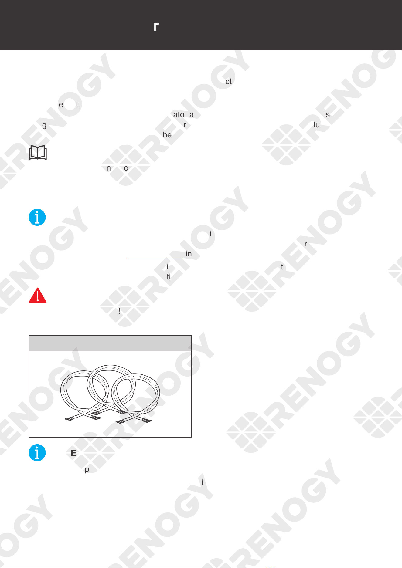
Essential Accessories
Signal Line X 3
NOT
E
z
There is no polarity requirement for the signal line.
z
Strip some insulation off the signal line by using a wire stripper according to the depth of the
wiring hole.
44
Automatic Generator Start
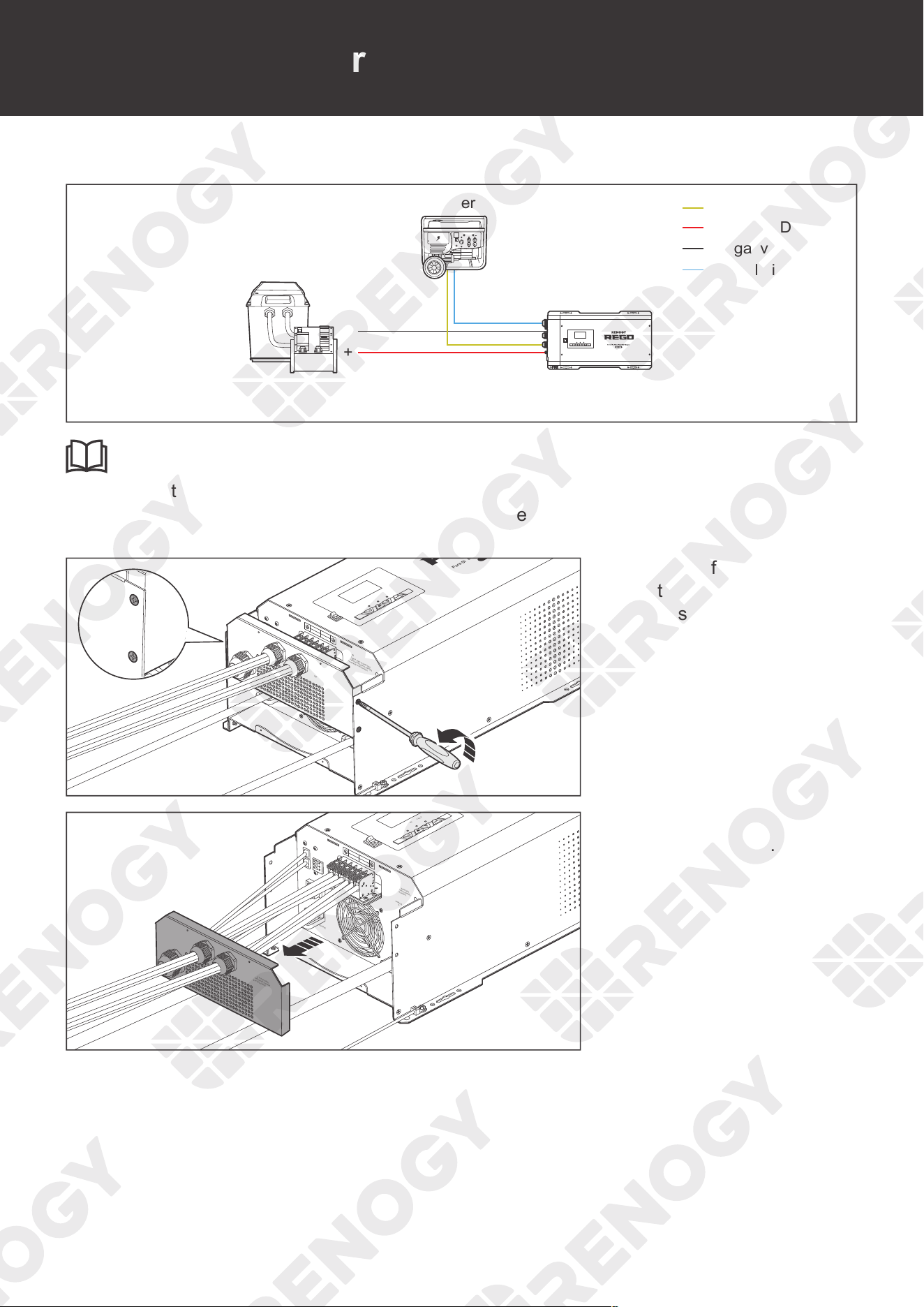
Wiring Diagram
AC Generator
AC Input
Dry Contact Relay
Terminal Block
Battery System (12V)
+
-
Positive (DC)
Negative (DC)
Signal Line
ON
OFF
AC/INV CHG FAULT
INF
O
z
Connect three signal lines to NC (normally closed contact), NO (normally open contact), and
C (common static contact) of the AC Input. For more instructions, read the user manual of
AC Input.
AC / INV
CHC
FAULT
Pure Sine Wave Inverter Charger
REMOTE
DRY
CAN
NO
NC
C
CONTACT
CHARCER W
PROT
WARNING
please read the instructions carefully
Before working on this product.
High voltage,in order to avoid risks,
L
L
N
OUTPUT
INPUT
N
NEGATIVE
WARNING
please read the instructions carefully
Before working on this product.
High voltage,in order to avoid risks,
OFF
ON
CHARCER W
PROT
NEGATIVE
please read the instructions carefully
Before working on this product.
High voltage,in order to avoid risks,
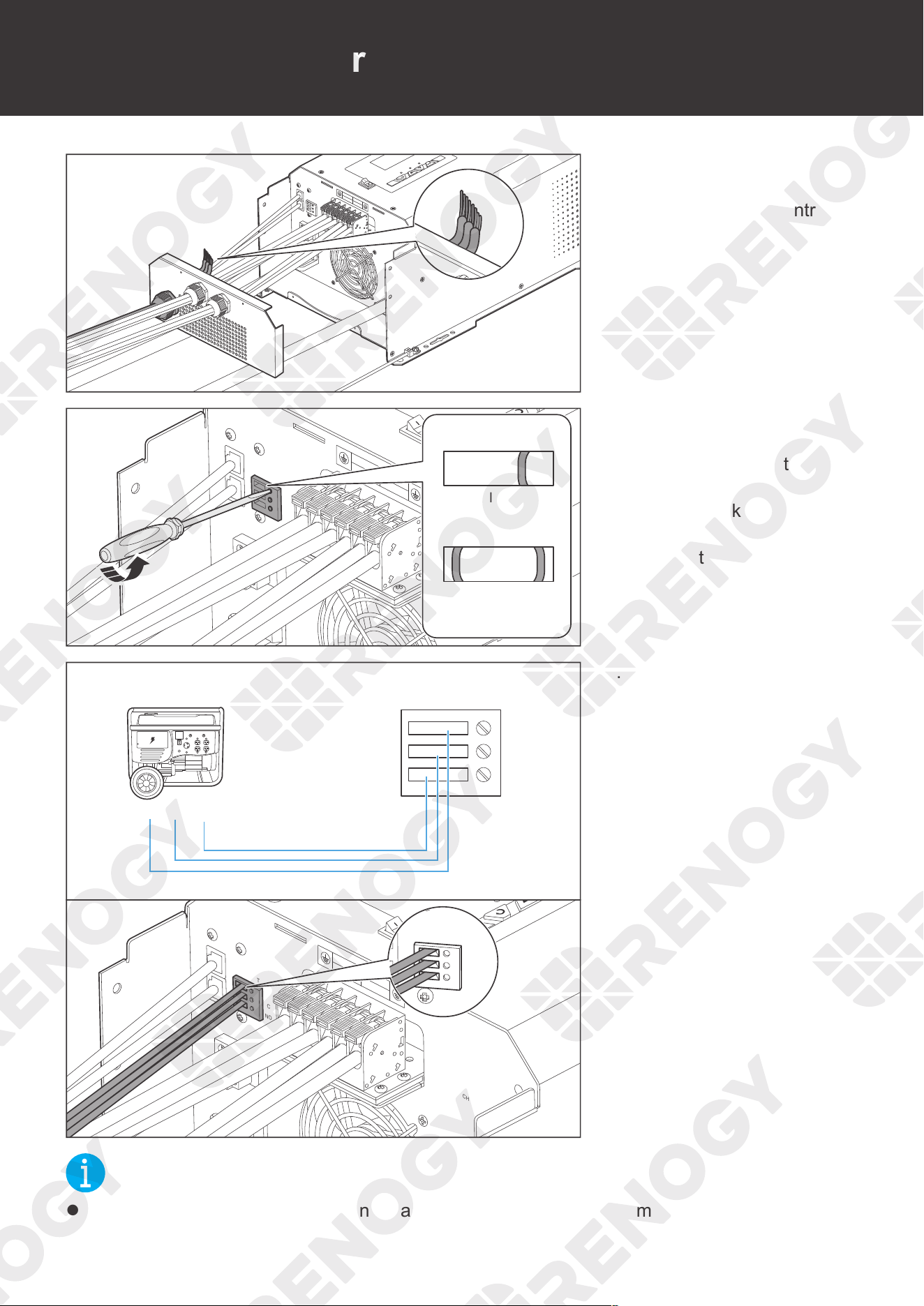
1. Remove four retaining
nuts of the AC Cable &
Accessory Plate by turning
them counterclockwise
with a Phillips screwdriver.
AC / INV
CHC
FAULT
REMOTE
DRY
CAN
NO
NC
C
CONTACT
CHARCER W
PROT
WARNING
please read the instructions carefully
Before working on this product.
High voltage,in order to avoid risks,
L
L
N
OUTPUT
INPUT
N
NEGATIVE
WARNING
please read the instructions carefully
Before working on this product.
High voltage,in order to avoid risks,
OFF
ON
2. Remove the AC Cable &
Accessory Plate.
45
Automatic Generator Start
AC / INV
CHC
FAULT
REMOTE
DRY
CAN
NO
NC
C
CONTACT
CHARCER W
PROT
WARNING
please read the instructions carefully
Before working on this product.
High voltage,in order to avoid risks,
L
L
N
OUTPUT
INPUT
N
NEGATIVE
WARNING
please read the instructions carefully
Before working on this product.
High voltage,in order to avoid risks,
OFF
REMOTE
DRY
CAN
NO
NC
C
CONTACT
WARNING
please read the instructions carefully
Before working on this product.
High voltage,in order to avoid risks,
NEGATIVE
WARNING
please read the instructions carefully
Before working on this product.
High voltage,in order to avoid risks,
OFF
ON
3. Run three signal lines
through the Remote &
Accessory Cable Entry.
OFF
ON
REMOTE
DRY
CAN
NO
NC
C
CONTACT
CHARCER W
PROT
WARNING
please read the instructions carefully
Before working on this product.
High voltage,in order to avoid risks,
L
L
N
OUTPUT
INPUT
N
Close
Open
4. Turn the cable retainer
screws of NC, C and
NO of Dry Contact
Relay Terminal BLock
counterclockwise with
a slotted screwdriver to
ensure that the cable
retainers are open.
OFF
ON
AC / INV
CHC
FAULT
REMOTE
DRY
CAN
NO
NC
C
CONTACT
CHARCER W
PROT
WARNING
please read the instructions carefully
Before working on this product.
High voltage,in order to avoid risks,
L
L
N
OUTPUT
INPUT
N
BTS
NO
NC
DRY
CONTACT
REMOTE
C
CAN
NC
NC
C
C
NO
NO
5. Connect three signal lines
to the corresponding NC,
C, and NO wiring holes.
NOT
E
z
Some generators only have NC (normally closed contact) and C (common static contact) or NO
(normally open contact) and C (common static contact). You can connect them on demand.
46
Automatic Generator Start
REMOTE
DRY
CAN
NO
NC
C
CONTACT
CHARCER W
PROT
WARNING
please read the instructions carefully
Before working on this product.
High voltage,in order to avoid risks,
L
L
N
OUTPUT
INPUT
N
OFF
ON
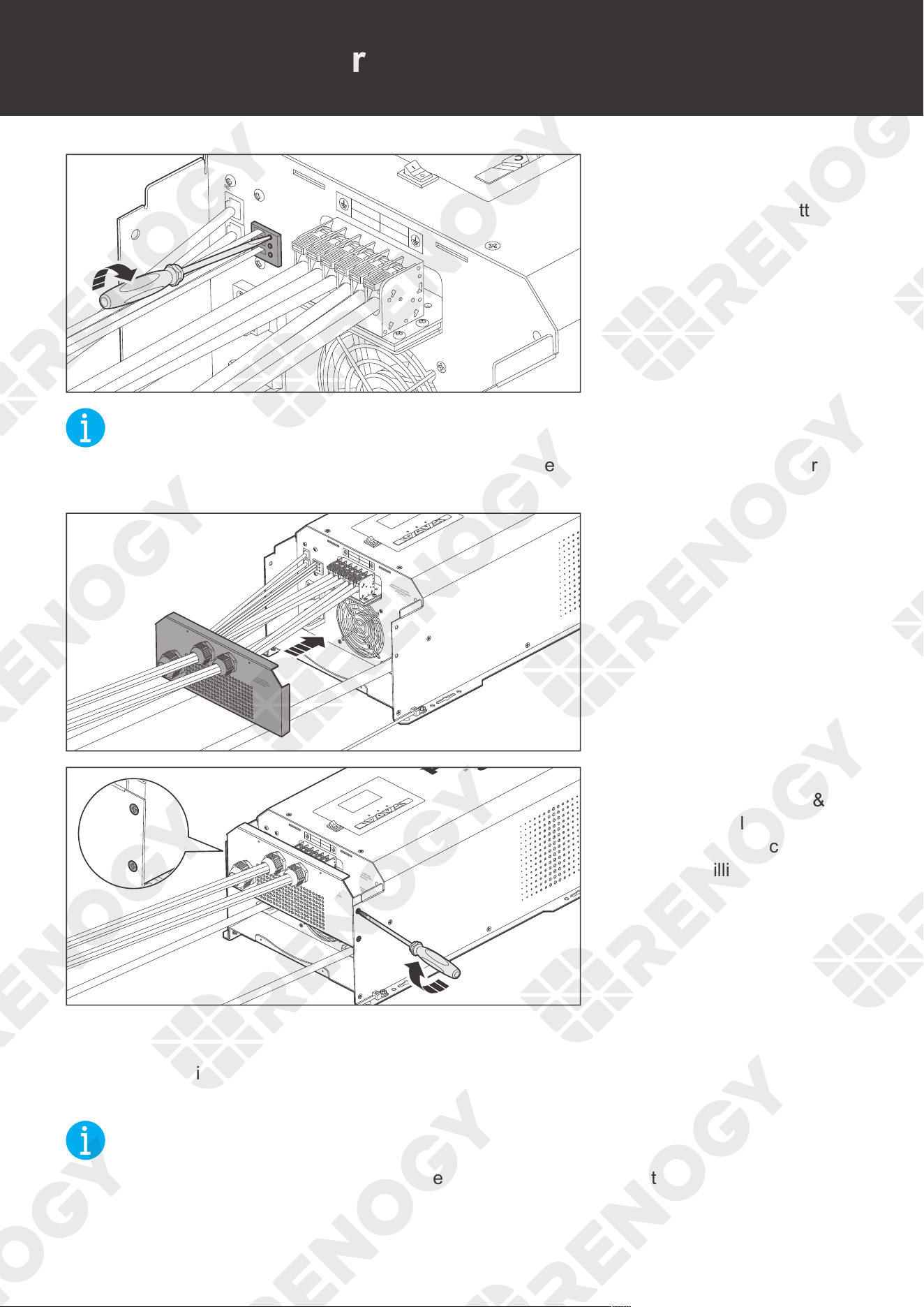
6. Turn the cable retainer
screws of NC, C and NO
clockwise with a slotted
screwdriver to fasten the
cable.
NOT
E
z
Do not overtighten the cable retainer screws. Otherwise it will lead to stripped screws or
screw bending.
AC / INV
CHC
FAULT
REMOTE
DRY
CAN
NO
NC
C
CONTACT
CHARCER W
PROT
WARNING
please read the instructions carefully
Before working on this product.
High voltage,in order to avoid risks,
L
L
N
OUTPUT
INPUT
N
NEGATIVE
WARNING
please read the instructions carefully
Before working on this product.
High voltage,in order to avoid risks,
OFF
ON
7. Install the AC Cable &
Accessory Plate.
AC / INV
CHC
FAULT
Pure Sine Wave Inverter Charger
REMOTE
DRY
CAN
NO
NC
C
CONTACT
CHARCER W
PROT
WARNING
please read the instructions carefully
Before working on this product.
High voltage,in order to avoid risks,
L
L
N
OUTPUT
INPUT
N
NEGATIVE
WARNING
please read the instructions carefully
Before working on this product.
High voltage,in order to avoid risks,
CHARCER W
PROT
NEGATIVE
please read the instructions carefully
Before working on this product.
High voltage,in order to avoid risks,
OFF
ON
8. Install four retaining
nuts of the AC Cable &
Accessory Plate by turning
them counterclockwise
with a Phillips screwdriver.
If your inverter charger uses the DC Generator as the power supply and the DC Generator can
automatically start or stop, you can connect the DC Generator to the inverter charger via the
signal line. The inverter charger will automatically start and stop the generator according to the
voltage you set. The signal line is connected in the same way as the AC Input.
NOT
E
z
Make sure that the DC Generator is properly connected to the inverter charger.
47
Communication
Communication
The communication connection is optional. The REGO Inverter Charger can communicate with
other REGO devices and monitoring devices, enabling safe operation, smart control, remote
monitoring, and programmable settings.
WARNIN
G
z
Risk of electric shock! Turn off the inverter charger and the power supply devices connected
to the inverter charger before connection.
z
Wear proper protective equipment and use insulated tools during operation. Be careful when
touching bare terminals of capacitors as they may retain high lethal voltages even after the
power is removed.
Inter-Device Communication
Depending on the installation condition, the RV-C communication connections between the
inverter charger and other REGO devices can be established with backbone or daisy chain
topology. The inter-device communication allows the inverter charger to dynamically adjust the
charging profile for an optimal and safe charge.
Backbone Topology
The backbone topology applies to RVs that are integrated with RV-C buses with built-in 120Ω
resistors on both ends. Check the RV user manual for details or contact the RV manufacturer if
necessary.
For technical support from Renogy, please contact us through renogy.com/contact-us/.
CAUTIO
N
z
Connect devices to the inverter charger according to the wiring diagram provided by the RV
manufacturer.
Choose proper communication cables according to your specific demands.
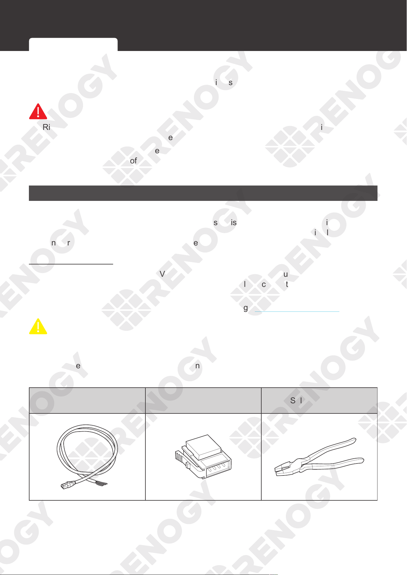
Recommended Accessories
LP16 Plug (7-Pin) to Bare
Drop Cables
Drop Plugs Split Joint Pliers
Inter-Device Communication Monitoring Device Communication
48
Communication
NOT
E
z
The drop cable shall not exceed 19.6 feet (6 m), and the RV-C bus shall not exceed 98.4
feet (30 m).
z
Different drop sockets are used on the RV-C bus by different RV manufacturers. Select the
Drop Plugs that match the drop sockets for the inter-device communication connections. If
you are not sure about the Drop Plug selection, check with the RV manufacturer
. This user
manual takes the Mini-Clamp II plug (4-Pin) as an example.
z
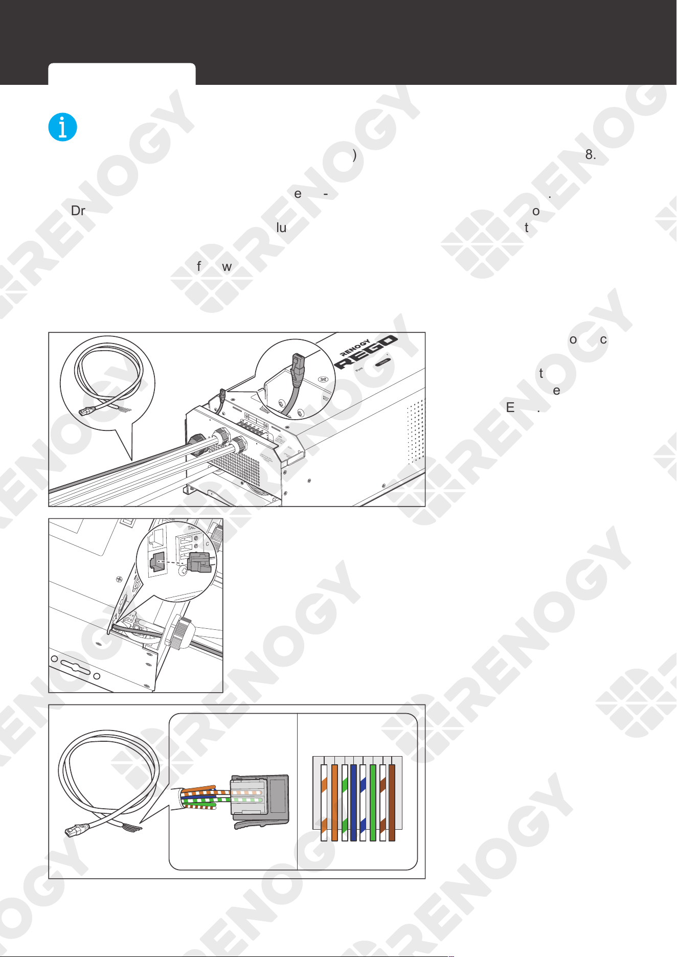
Different Drop Plugs follow different pinouts. Crimp the Drop Plugs on the Drop Cables
following the correct pinout. If you are not sure about the Drop Plug pinout, check with the
RV manufacturer. This user manual takes the pinout of the Mini-Clamp II plug (4-Pin) as an
example.
AC / INV
CHC
FAULT
Pure Sine Wave Inverter Charger
REMOTE
DRY
CAN
NO
NC
C
CONTACT
CHARCER W
PROT
WARNING
please read the instructions carefully
Before working on this product.
High voltage,in order to avoid risks,
L
L
N
OUTPUT
INPUT
N
NEGATIVE
WARNING
please read the instructions carefully
Before working on this product.
High voltage,in order to avoid risks,
OFF
ON
OFF
ON
REMOTE
DRY
CAN
NO
NC
C
CONTACT
WARNING
please read the instructions carefully
Before working on this product.
High voltage,in order to avoid risks,
L
L
N
OUTPUT
INPUT
N
WARNING
please read the instructions carefully
Before working on this product.
High voltage,in order to avoid risks,
1. Insert the RJ45 connector
of RJ45 Plug to the Bare
Drop Cable through the
Remote & Accessory
Cable Entry.
ON
OFF
NO
NC
C
DRY
CONTACT
BTS
CAN
REMOTE
DRY
CONTACT
NC
C
NO
2. Connect the RJ45 connector to the Communication Port
(CAN Bus).
4321
12345678
3. The white green CAN_H
wire goes to pin 2 and the
white orange CAN_L wire
goes to pin 3. Leave pin 1
and pin 4 empty.
Inter-Device Communication Monitoring Device Communication
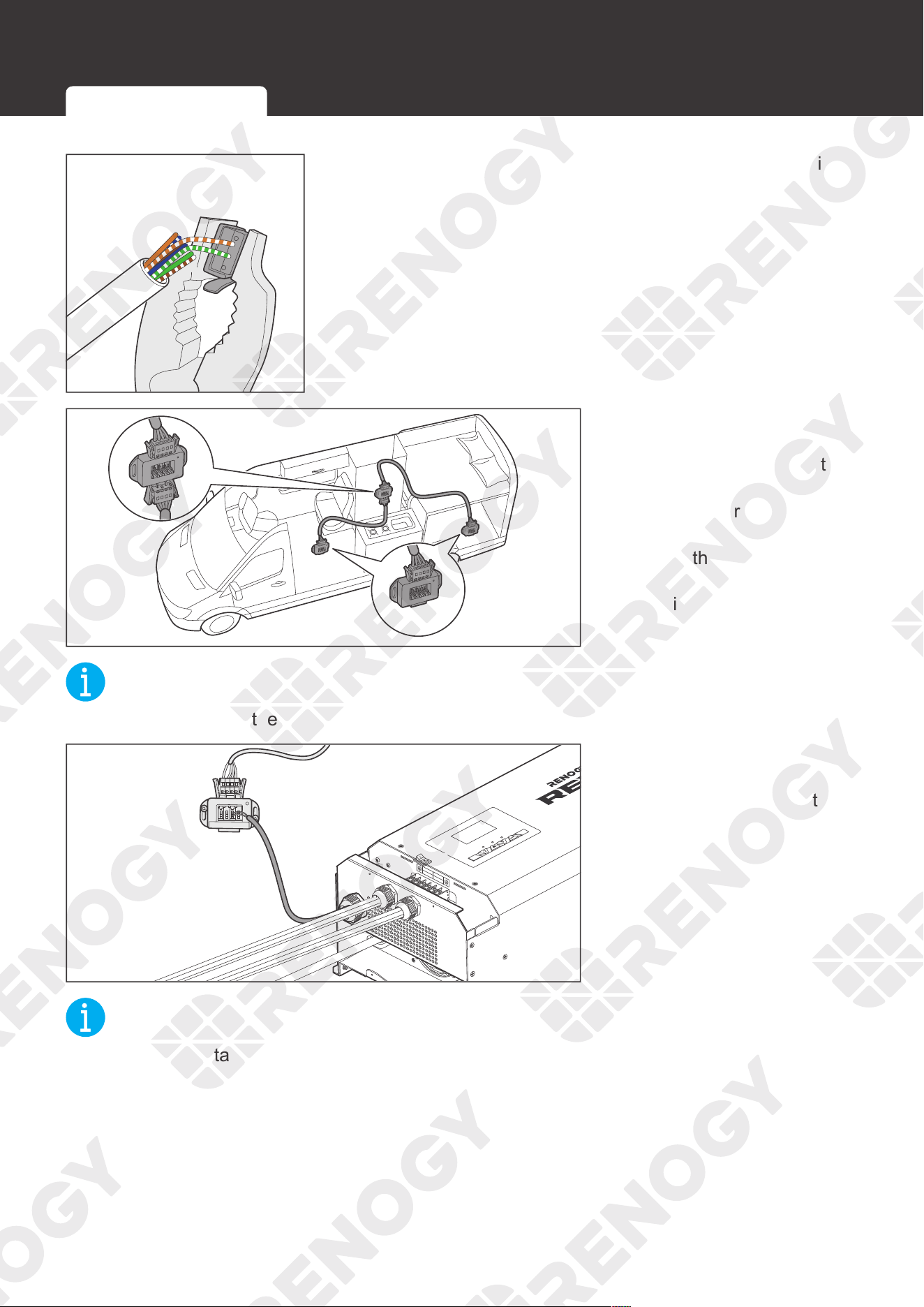
49
Communication
4. Squeeze the crimp areas of the Drop Plugs with the Split
Joint Pliers.
5. Locate the drop tap (not
included) on the RV-C
bus that is the closest to
the installation site of the
inverter charger. The drop
taps are usually located
above the entry door, in
the bathroom, or under the
bed in the RV.
NOT
E
z
If you fail to locate the drop taps, please contact the RV manufacturer for help.
AC / INV
CHC
FAULT
Pure Sine Wave Inverter Charger
REMOTE
DRY
CAN
NO
NC
C
CONTACT
CHARCER W
PROT
WARNING
please read the instructions carefully
Before working on this product.
High voltage,in order to avoid risks,
L
L
N
OUTPUT
INPUT
N
NEGATIVE
WARNING
please read the instructions carefully
Before working on this product.
High voltage,in order to avoid risks,
OFF
ON
6. Connect the Drop Plugs
on the drop cables and
other REGO devices to
the drop sockets on the
drop tap.
NOT
E
z
Different drop taps are used on the RV-C bus by different RV manufacturers. This user
manual takes the 4-socket drop tap as an example.
Inter-Device Communication Monitoring Device Communication
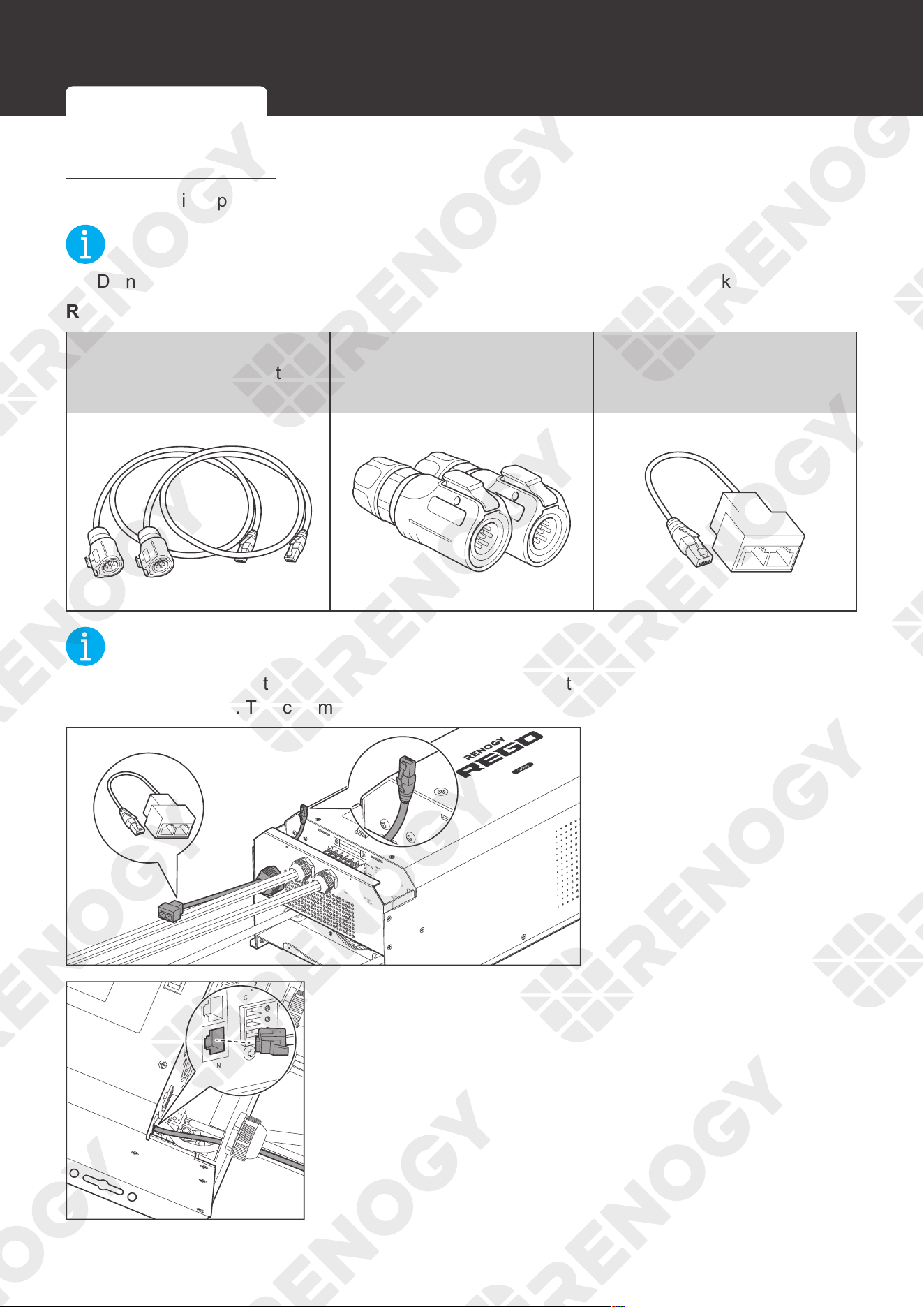
50
Communication
Daisy Chain Topology
The daisy chain topology applies to RVs that are not integrated with RV-C buses.
NOT
E
z
Do not place the inverter charger at the first or last of the daisy chain network.
Recommended Accessories
LP16 Plug (7-Pin) to RJ45
Communication Adapter
Cable
LP16 Terminator Plug (7-Pin)
RJ45 Network 1 to 2 Port
Ethernet Adapter Splitter
NOT
E
z
Select the appropriate communication cable (sold separately) according to the distance
between devices. The communication cable should be less than 19.6 feet (6 m).
AC / INV
CHC
FAULT
Pure Sine Wave Inverter Charger
REMOTE
DRY
CAN
NO
NC
C
CONTACT
CHARCER W
PROT
WARNING
please read the instructions carefully
Before working on this product.
High voltage,in order to avoid risks,
L
L
N
OUTPUT
INPUT
N
NEGATIVE
WARNING
please read the instructions carefully
Before working on this product.
High voltage,in order to avoid risks,
OFF
ON
OFF
ON
REMOTE
DRY
CAN
NO
NC
C
CONTACT
WARNING
please read the instructions carefully
Before working on this product.
High voltage,in order to avoid risks,
L
L
N
OUTPUT
INPUT
N
WARNING
please read the instructions carefully
Before working on this product.
High voltage,in order to avoid risks,
1. Insert the RJ45 connector
of RJ45 Network 1 to 2
Port Ethernet Adapter
Splitter through the
Remote & Accessory
Cable Entry.
ON
OFF
NO
NC
C
DRY
CONTACT
BTS
CAN
REMOTE
DRY
CONTACT
NC
C
NO
2. Connect the RJ45 connector to the Communication Port
(CAN Bus).
Inter-Device Communication Monitoring Device Communication
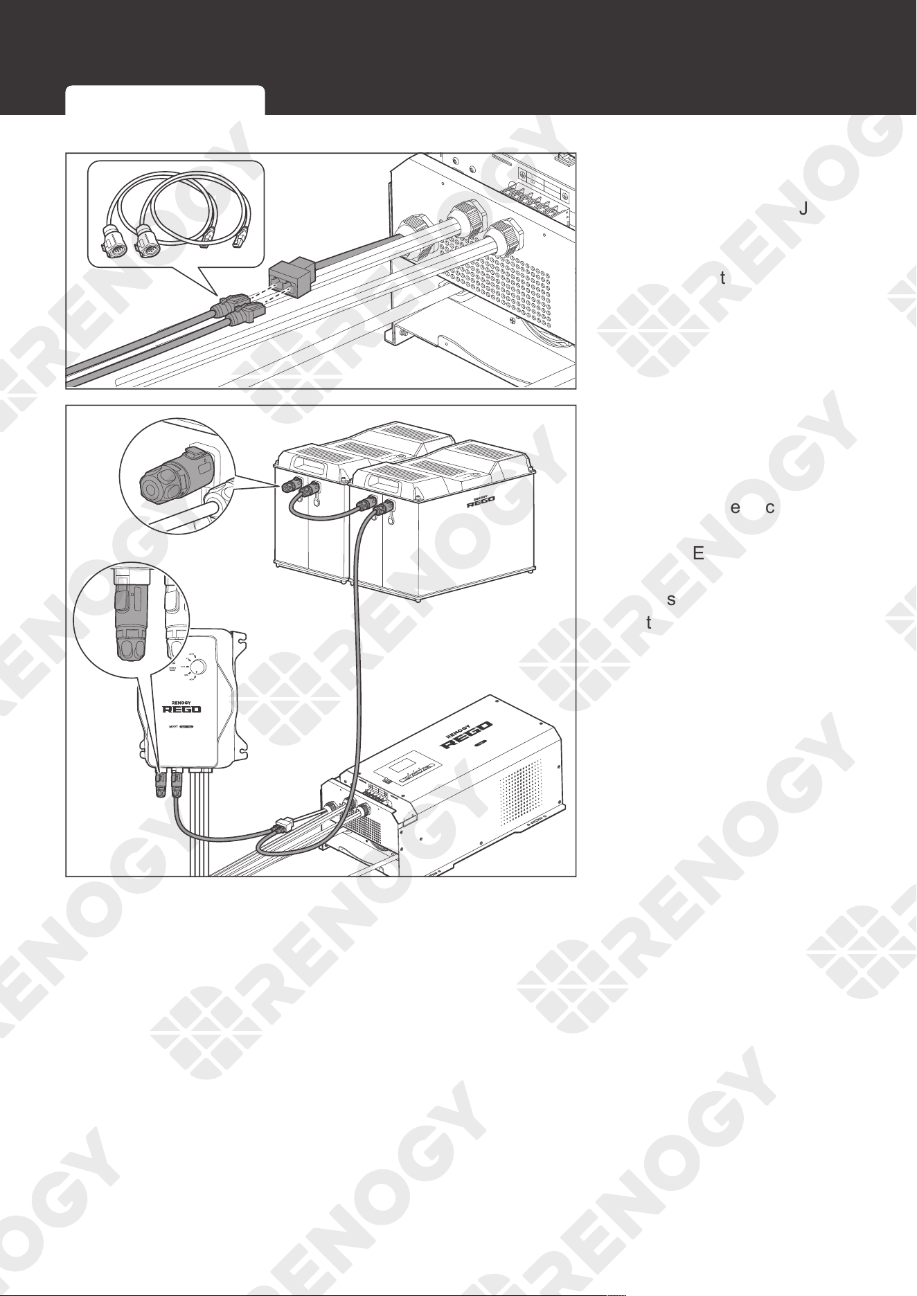
51
Communication
REMOTE
DRY
CAN
NO
NC
C
CONTACT
L
L
N
OUTPUT
INPUT
N
NEGATIVE
WARNING
please read the instructions carefully
Before working on this product.
High voltage,in order to avoid risks,
OFF
ON
3. Connect the two RJ45
connectors of LP16
Plug (7-Pin) to the RJ45
Communication Adapter
Cables to the RJ45
Network 1 to 2 Port
Ethernet Adapter Splitter.
AC / INV
CHC
FAULT
Pure Sine Wave Inverter Charger
REMOTE
DRY
CAN
NO
NC
C
CONTACT
CHARCER W
PROT
WARNING
please read the instructions carefully
Before working on this product.
High voltage,in order to avoid risks,
L
L
N
OUTPUT
INPUT
N
NEGATIVE
WARNING
please read the instructions carefully
Before working on this product.
High voltage,in order to avoid risks,
OFF
ON
4. Connect the other
ends of the LP16
Plug (7-Pin) to RJ45
Communication Adapter
Cables to the vacant CAN
communication ports of
other REGO devices.
Insert the terminal
plugs (sold separately)
into the vacant CAN
communication port of
the first and last REGO
devices.
Inter-Device Communication Monitoring Device Communication
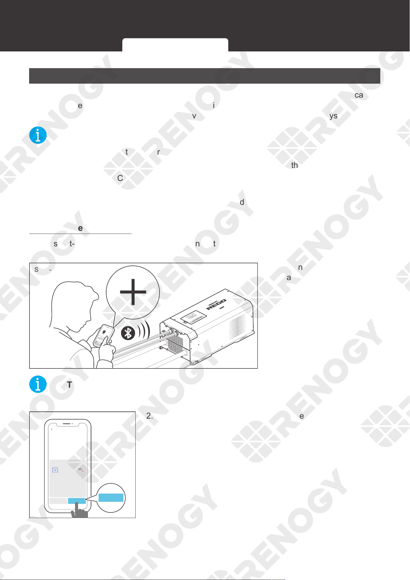
52
Communication
Monitoring Device Communication
Depending on the application, the short-range or long-range communication connections can be
established between the inverter charger and monitoring devices. The monitoring device allows
for the monitoring and programming of the inverter charger or even the complete system.
NOT
E
z
Make sure the Bluetooth of your phone is turned on.
z
Scan the QR code on the last page of the user manual to download the DC Home app.
z
The version of the DC Home app might have been updated. Illustrations in the user manual
are for reference only. Follow the instructions based on the current app version.
z
Make sure that the inverter charger is properly installed and powered on before it is paired
with the DC Home app.
Short-Range Monitoring
If only short-range monitoring is required, connect the inverter charger to the DC Home app
directly through the Bluetooth of your phone.
AC / INV
CHC
OFF
ON
FAULT
ARNING
please read the instructions carefully
Before working on this product.
High voltage,in order to avoid risks,
Pure Sine Wave Inverter Charger
CHARGING
LI
OUTPUTBATT
INPUTBATT
100%
25%
BYPASS
Short-Range Monitoring
My Renogy
75%
A
Device
Devices
Battery
RBT12400LFPL-
...
Controller
Scene Community Personal
Commonly
RCC60RVRU
%
25
A
0
0
W
0
10
h left
Security
Night
1. Open the DC Home app.
Tap + to search for new
devices.
NOT
E
z
Keep the phone within 10 feet (3 m) of the inverter charger.
Cancel Confirm
BT-TH-161CFF52
RIV1230RCL-1SS
Found Devices
ConfirmConfirm
2. Tap Confirm to add the newly found device to the device
list.
Inter-Device Communication Monitoring Device Communication
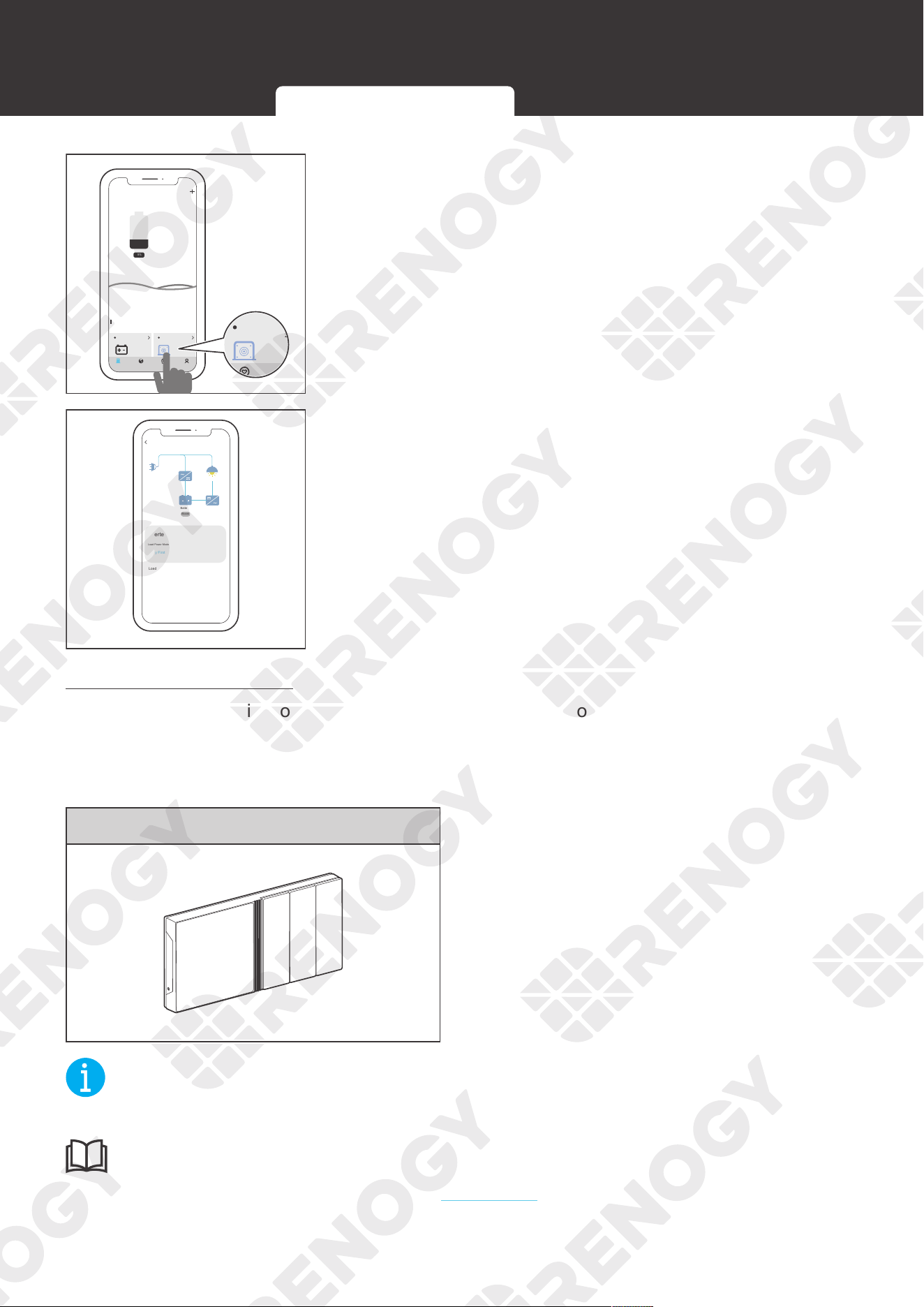
53
Communication
My Renogy
25%
A
Device
Device
Battery
RBT12400LFPL-...
Inverter
Scene Community Me
RIV1230RCL-1SS
BT-TH-161CFF52
%
25
A
0 12.0 V
W
0
25%
A
Device
Device
Battery
RBT12400LFPL-...
Inverter
Scene Community Me
RIV1230RCL-1SS
BT-TH-161CFF52
%
25
A
0 12.0 V
W
0
3. Tap the inverter icon to enter the device information
interface.
RIV1230RCL-1SS
Shore Power
Battery
Load
Boost
Inverter/Solar Charging Screen
Load Power Mode
Load Watts
Load Volts
Load Amps
Inveter Output Hz
Battery Charging Watts
Battery Vots
Charge Priority
BULK ChargeUtility First Utility First
1000
120
10
A
60
Hz
200
W
12
V
V
W
Status
4. Check the operation status of the inverter charger in this
interface.
Long-Range Monitoring
If long-range communication and programming are required, connect the inverter charger to
Renogy ONE through Bluetooth or wires, and the Renogy ONE to the DC Home app through
Wi-Fi.
Recommended Accessories
Renogy ONE
NOT
E
z
Make sure that the Renogy ONE is powered on before the connection.
INF
O
z
Read the user manual of Renogy ONE at renogy.com before the connection.
Inter-Device Communication Monitoring Device Communication
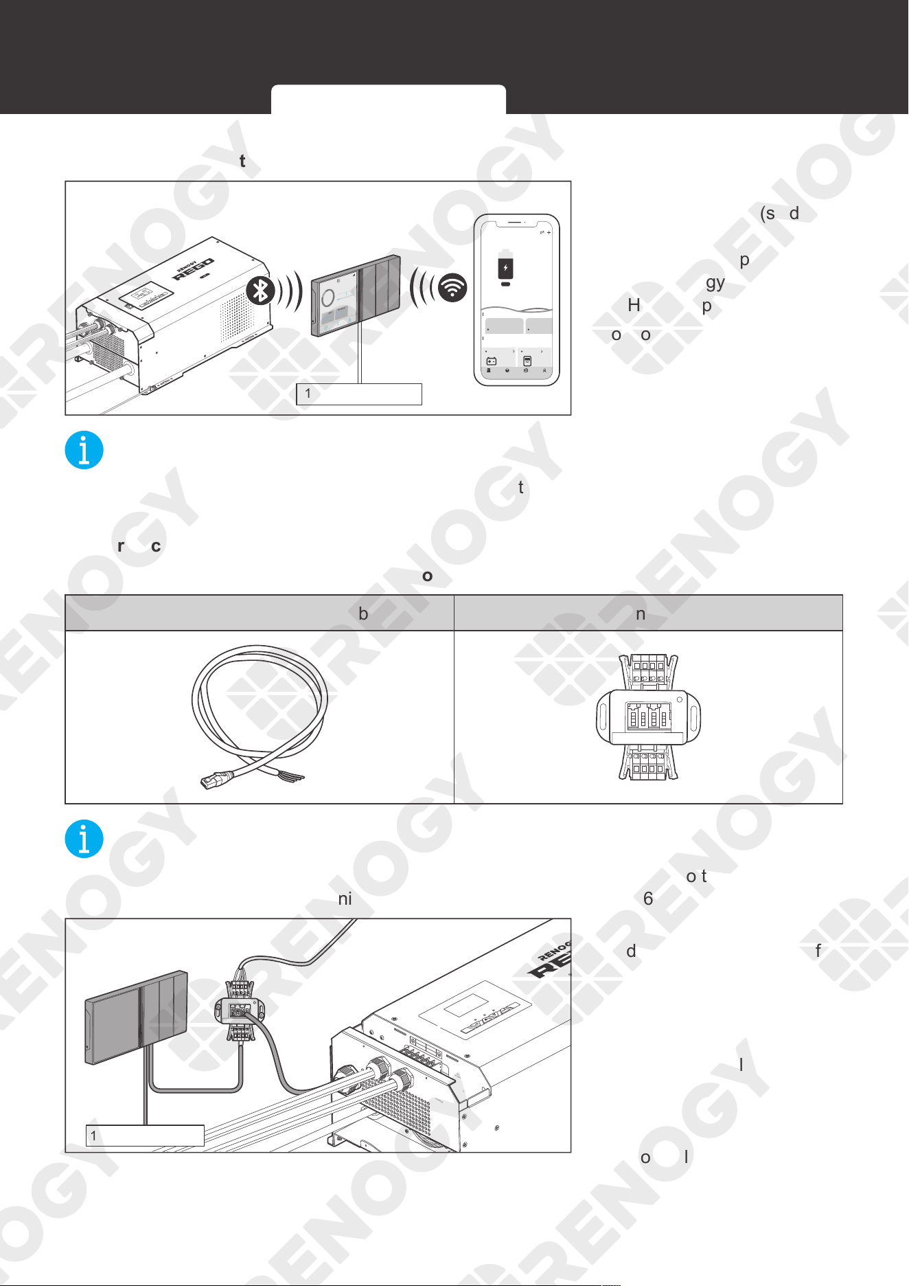
54
Communication
█
Wireless connection
AC / INV
CHC
OFF
ON
FAULT
ARNING
please read the instructions carefully
Before working on this product.
High voltage,in order to avoid risks,
Pure Sine Wave Inverter Charger
CHARGING
LI
OUTPUTBATT
INPUTBATT
100%
25%
BYPASS
12V Power Supply
12:33
12/23
FULLY
2d13h
2.33A
CHARED IN
80
%
CURRENT
RBT1000HJD
80%
1000
HOME
Device
Setting
Ah
RBT1000HJD
0W
0
My Renogy
75%
A
Device
Devices
Battery
RBT12400LFPL-...
Controller
Scene Community Personal
Commonly
RCC60RVRU
%
25
A
0 0
W
0
10h left
Security Night
Connect the inverter charger
to the Renogy ONE (sold
separately) through the
Bluetooth of your phone, and
pair the Renogy ONE with the
DC Home app through Wi-Fi.
Monitor the inverter charger
on the Renogy ONE or the DC
Home app.
NOT
E
z
Make sure the inverter charger does not communicate with any other device.
z
Keep the phone within 10 feet (3 m) of the inverter charger.
█
Wired connection
Recommended Accessories (Backbone Topology)
RJ45 Plug to Bare Drop Cable Common Drop Tap
NOT
E
z
Select the appropriate communication cable (sold separately) according to the distance
between devices. The communication cable should be less than 19.6 feet (6 m).
Backbone Topology
AC / INV
CHC
FAULT
Pure Sine Wave Inverter Charger
REMOTE
DRY
CAN
NO
NC
C
CONTACT
CHARCER W
PROT
WARNING
please read the instructions carefully
Before working on this product.
High voltage,in order to avoid risks,
L
L
N
OUTPUT
INPUT
N
NEGATIVE
WARNING
please read the instructions carefully
Before working on this product.
High voltage,in order to avoid risks,
12V Power Supply
1. Replace the terminated
drop tap at either end of
the RV-C bus with the
Common Drop Tap (not
included). Secure the
bare wires of the Drop
Cable (not included) onto
the terminal block plug of
the Common Drop Tap
following the terminal
block plug pinout. Plug the
Drop Cable to the RJ45
port of Renogy ONE.
Inter-Device Communication Monitoring Device Communication
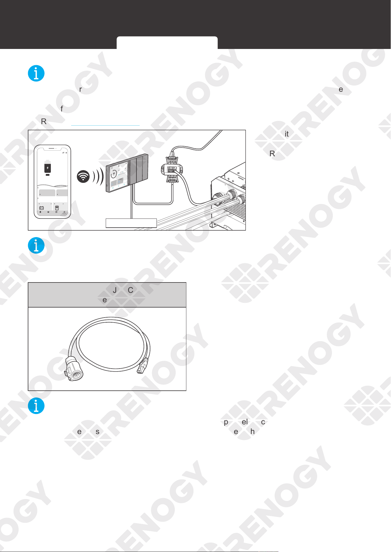
55
Communication
NOT
E
z
Different terminal block plugs are used on different Common Drop Taps and follow different
pinouts. If you are unsure about the pinout of the terminal block plug, contact the RV
manufacturer.
z
Refer to Backbone Topology for more instructions.
12:33
12/23
FULLY
2d13h
2.33A
CHARED IN
80
%
CURRENT
RBT1000HJD
80%
1000
HOME
Device
Setting
Ah
RBT1000HJD
0W
0
REMOTE
DRY
CAN
NO
NC
C
CONTACT
NEGATIVE
12V Power Supply
My Renogy
75%
A
Device
Devices
Battery
RBT12400LFPL-...
Controller
Scene Community Personal
Commonly
RCC60RVRU
%
25
A
0 0
W
0
10h left
Security Night
2. Monitor and program
the complete system on
Renogy ONE or the DC
Home app.
NOT
E
z
Keep the phone within 10 feet (3 m) of the inverter charger.
Recommended Accessories (Daisy Chain Topology)
LP16 Plug (7-Pin) to RJ45 Communication
Adapter Cable
NOT
E
z
Select the appropriate communication cable (sold separately) according to the distance
between devices. The communication cable should be less than 19.6 feet (6 m).
Inter-Device Communication Monitoring Device Communication
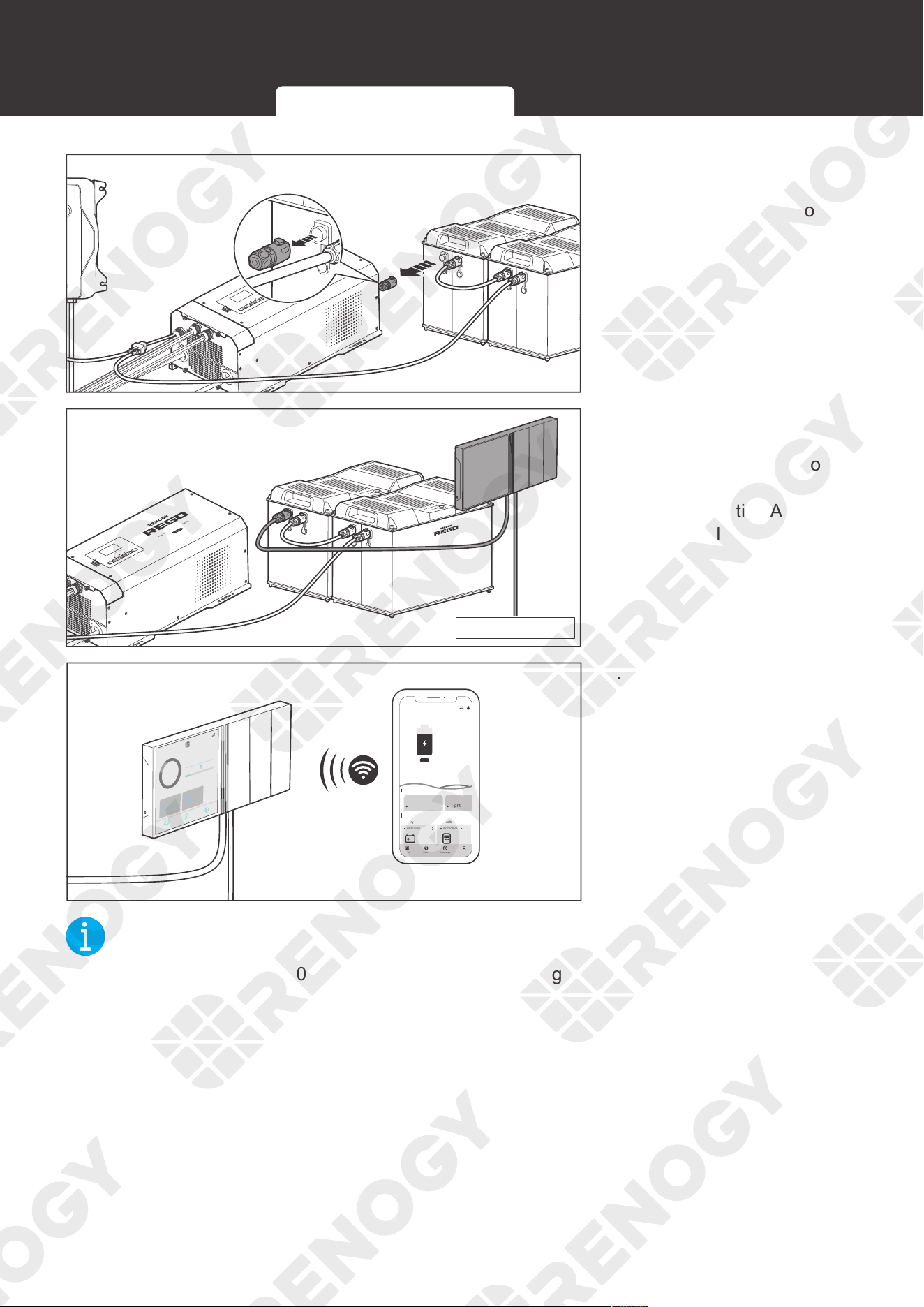
56
Communication
AC / INV
CHC
FAULT
Pure Sine Wave Inverter Charger
REMOTE
DRY
CAN
NO
NC
C
CONTACT
CHARCER W
PROT
WARNING
please read the instructions carefully
Before working on this product.
High voltage,in order to avoid risks,
L
L
N
OUTPUT
INPUT
N
NEGATIVE
WARNING
please read the instructions carefully
Before working on this product.
High voltage,in order to avoid risks,
Daisy Chain Topology
OFF
ON
1. Remove the Terminator
Plug from the REGO
device at either end of the
daisy chain.
AC / INV
CHC
FAULT
Pure Sine Wave Inverter Charger
DRY
NO
NC
C
CONTACT
CHARCER W
PROT
WARNING
please read the instructions carefully
Before working on this product.
High voltage,in order to avoid risks,
L
L
N
OUTPUT
INPUT
N
NEGATIVE
WARNING
please read the instructions carefully
Before working on this product.
High voltage,in order to avoid risks,
12V Power Supply
OFF
ON
2. Connect the Renogy
ONE to the free CAN
Communication Port on
the REGO device with the
Communication Adapter
Cable (sold separately).
My Renogy
75%
A
Device
Devices
Battery
RBT12400LFPL-...
Controller
Scene Community Personal
Commonly
RCC60RVRU
%
25
A
0 0
W
0
10
h left
Security Night
12:33
12/23
FULLY
2d13h
2.33A
CHARED IN
80
%
CURRENT
RBT1000HJD
80%
1000
HOME
Device
Setting
Ah
RBT1000HJD
0W
0
3. Pair Renogy ONE with the
DC Home app. Monitor
and program the complete
system on the Renogy
ONE or the DC Home app.
NOT
E
z
Keep the phone within 10 feet (3 m) of the inverter charger.
Inter-Device Communication Monitoring Device Communication
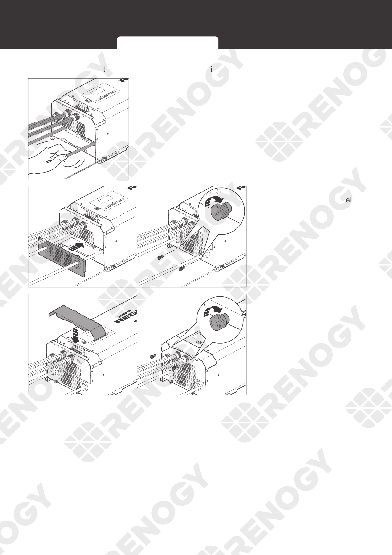
57
Putting Plates Back
Putting Plates Back
Reinstall the plates into the inverter charger after wiring.
AC / INV
CHC
FAULT
Pure Sine Wave Inverter Charger
REMOTE
DRY
CAN
NO
NC
C
CONTACT
CHARCER W
PROT
WARNING
please read the instructions carefully
Before working on this product.
High voltage,in order to avoid risks,
L
L
N
OUTPUT
INPUT
N
NEGATIVE
WARNING
please read the instructions carefully
Before working on this product.
High voltage,in order to avoid risks,
OFF
ON
1. Check and make sure all cable connections are tight and
secure.
AC / INV
CHC
OFF
ON
FAULT
Pure Sine Wave Inverter Charger
REMOTE
DRY
CAN
NO
NC
C
CONTACT
CHARCER W
PROT
WARNING
please read the instructions carefully
Before working on this product.
High voltage,in order to avoid risks,
L
L
N
OUTPUT
INPUT
N
NEGATIVE
WARNING
please read the instructions carefully
Before working on this product.
High voltage,in order to avoid risks,
AC / INV
CHC
FAULT
Pure Sine Wave Inverter Charger
REMOTE
DRY
CAN
NO
NC
C
CONTACT
CHARCER W
PROT
WARNING
please read the instructions carefully
Before working on this product.
High voltage,in order to avoid risks,
L
L
N
OUTPUT
INPUT
N
NEGATIVE
WARNING
please read the instructions carefully
Before working on this product.
High voltage,in order to avoid risks,
OFF
ON
2. Install the DC Cable Plate
and drive the two panel
screws clockwise to fix the
plate.
AC / INV
CHC
FAULT
Pure Sine Wave Inverter Charger
REMOTE
DRY
CAN
NO
NC
C
CONTACT
CHARCER W
PROT
WARNING
please read the instructions carefully
Before working on this product.
High voltage,in order to avoid risks,
L
L
N
OUTPUT
INPUT
N
NEGATIVE
WARNING
please read the instructions carefully
Before working on this product.
High voltage,in order to avoid risks,
AC / INV
CHC
FAULT
Pure Sine Wave Inverter Charger
REMOTE
DRY
CAN
NO
NC
C
CONTACT
CHARCER W
PROT
WARNING
please read the instructions carefully
Before working on this product.
High voltage,in order to avoid risks,
L
L
N
OUTPUT
INPUT
N
NEGATIVE
WARNING
please read the instructions carefully
Before working on this product.
High voltage,in order to avoid risks,
OFF
ON
OFF
ON
3. Install the Top Plate. Drive
the two panel screws
clockwise to fix the plate.
Inter-Device Communication Monitoring Device Communication
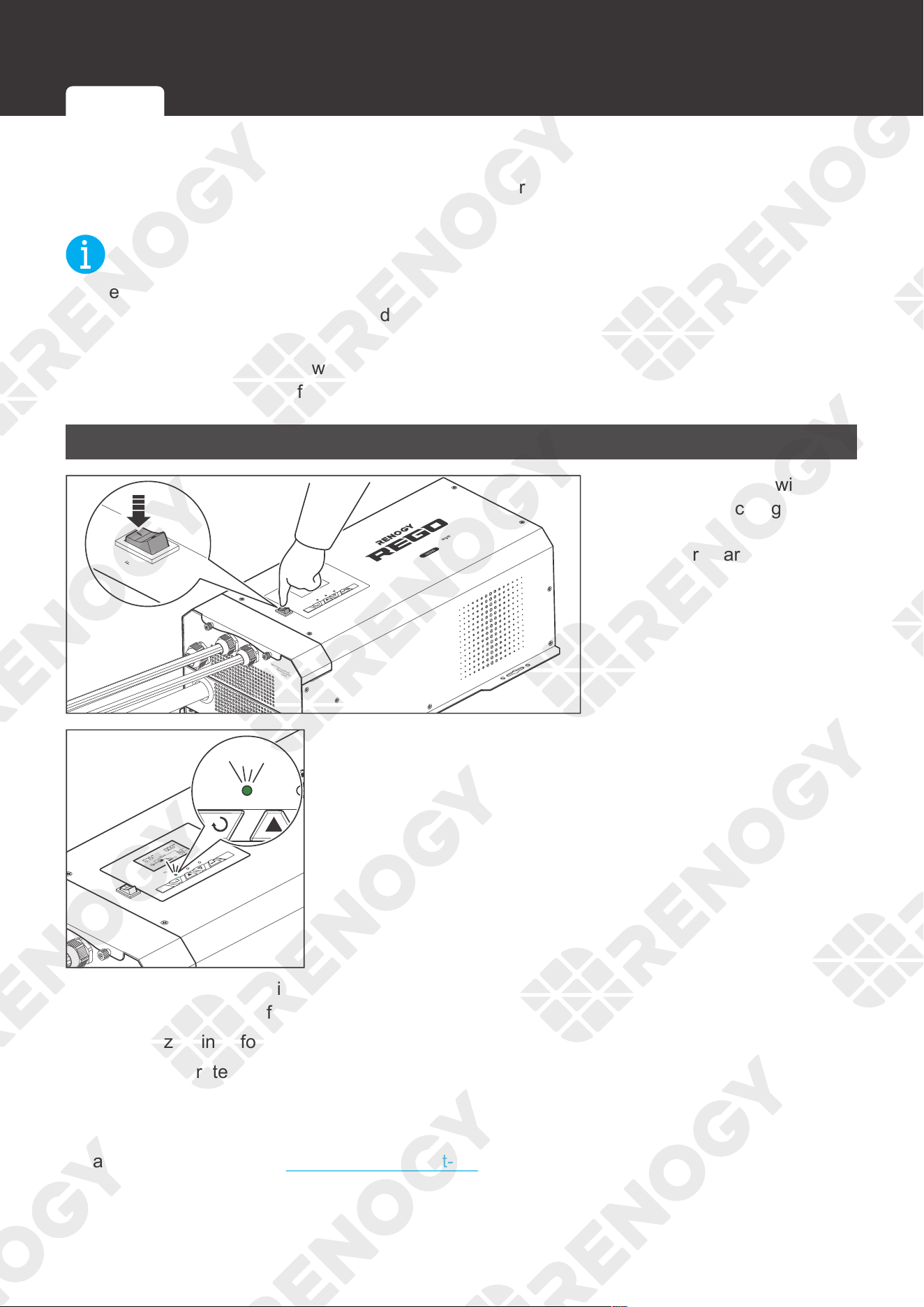
58
Power on
Power on
After installation, power on the battery and the AC input connected to the inverter charger, then
turn on the inverter charger. REGO 12V 3000W Inverter Charger can be powered on via the
main switch or wired remote control.
NOT
E
z
Before the inverter charger is powered on, ensure that the load is turned off. Otherwise the
inverter charger may be overloaded.
z
After the inverter charger is turned on, it will enter the self-test mode. The buzzer will sound
for 7 seconds and the fan will turn automatically at the same time. The self-test takes about
one minute. After the self-test, the sound disappears, and the fan stops running.
Main Switch
AC / INV
CHC
OFF
ON
FAULT
ARNING
please read the instructions carefully
Before working on this product.
High voltage,in order to avoid risks,
Pure Sine Wave Inverter Charger
AC / INV
CHC
OFF
ON
1. Press the main switch of
the inverter charger to the
"ON" position to power the
inverter charger on.
AC / INV
CHC
OFF
ON
FAULT
ARNING
please read the instructions carefully
Before working on this product.
High voltage,in order to avoid risks,
Pure Sine Wave Inverter Charger
CHARGING
LI
OUTPUTBATT
INPUTBATT
100%
25%
BYPASS
AC/INV CHG
2. The screen lights up and displays the status after the
inverter charger is powered on. The AC/INV indicator will
light up based on the usage.
After the inverter charger is properly installed and powered on, the inverter charger works
normally when all of the following conditions are met:
z
The buzzer rings for 7 seconds
z
The fan operates with the sound
z
The screen lights up
z
The indicator lights up
Please contact us through renogy.com/contact-us/.
Main Switch Wired Remote Control
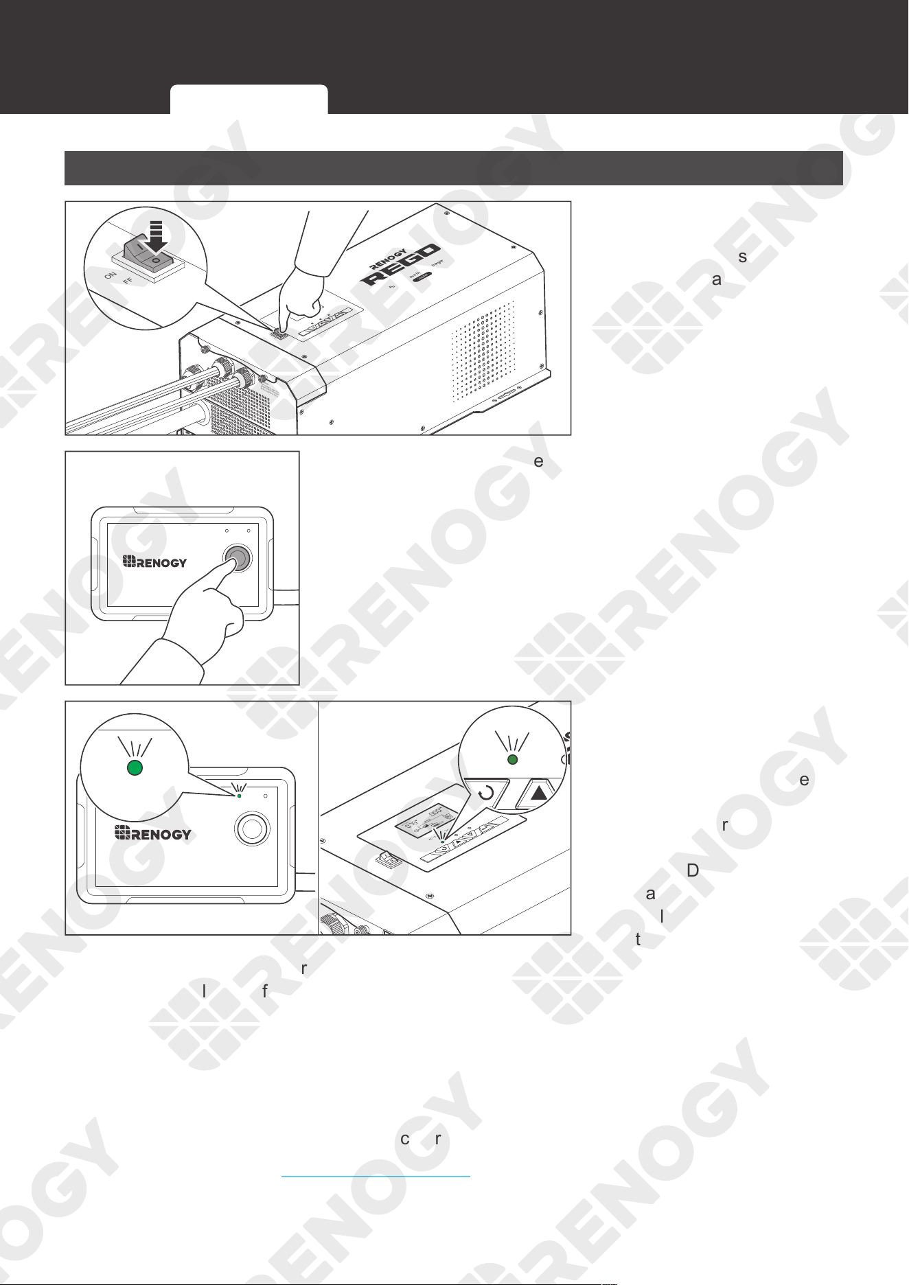
59
Power on
Wired Remote Control
AC / INV
CHC
OFF
ON
FAULT
ARNING
please read the instructions carefully
Before working on this product.
High voltage,in order to avoid risks,
Pure Sine Wave Inverter Charger
AC / INV
OFF
ON
1. If you use the wired
remote control, please
turn the main switch of the
inverter charger to "OFF"
first.
ON ERR
RMS-P2
2. Press the button on the wired remote control.
ON ERR
RMS-P2
ON ERR
AC / INV
CHC
OFF
ON
FAULT
ARNING
Pure Sine Wave Inverter Charger
CHARGING
LI
OUTPUTBATT
INPUTBATT
100%
25%
BYPASS
AC/INV CHG
3. After the inverter charger
is powered on, the ON
indicator of the wired
remote control and the
AC/INV indicator of the
inverter charger will light
up based on the usage.
The LCD of the inverter
charger lights up and
displays the operation
status.
After the inverter charger is properly installed and powered on, the inverter charger works
normally when all of the following conditions are met:
z
The buzzer rings for 7 seconds
z
The fan operates with the sound
z
The screen lights up
z
The indicator lights up
z
The ON indicator of the wired remote control lights up
Please contact us through renogy.com/contact-us/.
Main Switch Wired Remote Control
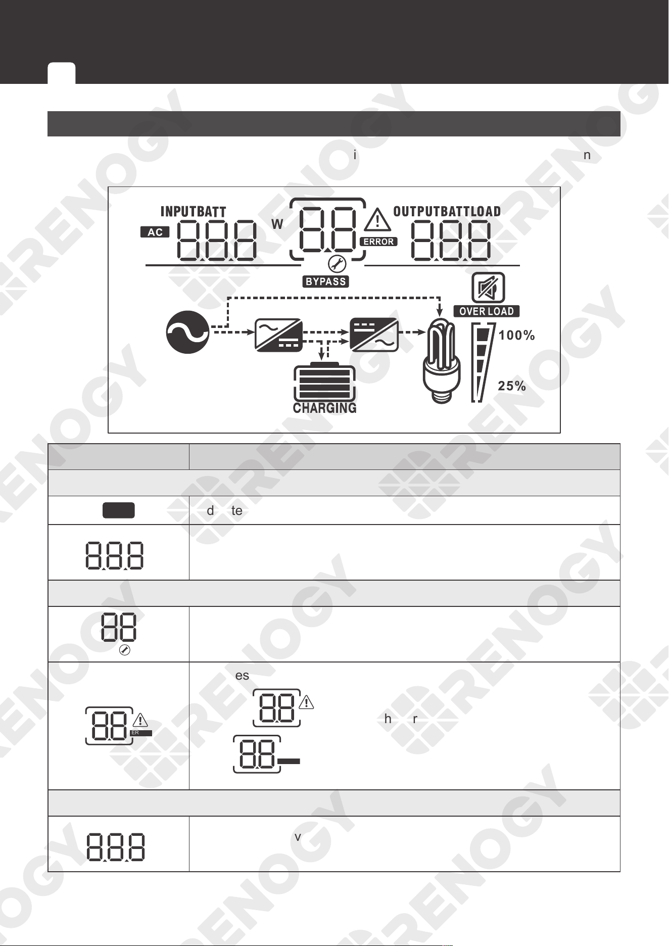
60
Operation
Operation
LCD
You can view the current operation status and warning messages of the inverter charger on the
LCD.
KW
VA
Hz
%
KW
VA
Hz
C
%
Icon Function Description
Input Source Information
AC
Indicates the AC input.
VA
%
C
KW
Hz
INPUTBATT
Indicates input voltage, input frequency, battery voltage, and charger
current.
Configuration Program and Fault Information
Indicates setting programs.
ERROR
Indicates the warning and fault codes.
Warning:
flashing with warning code.
Fault:
ERROR
lighting with fault code.
Output Information
VA
%
KW
Hz
OUTPUTBATTLOAD
Indicates output voltage, output frequency, load percent, load in VA,
load in Watt, and discharging current.
LCD Button Setting Battery Type User Mode
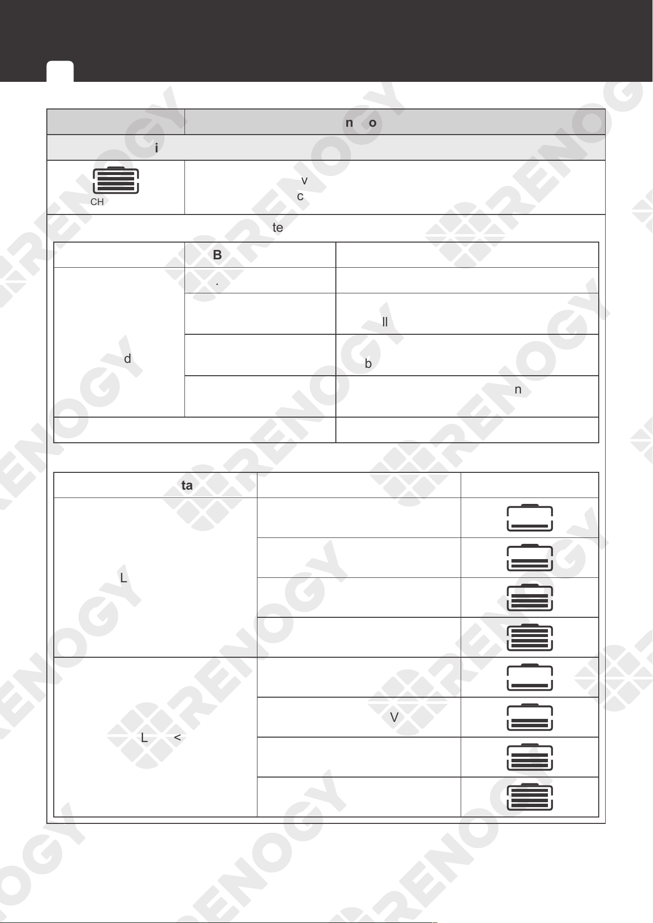
61
Operation
Icon Function Description
Battery Information
CHARGING
Indicates battery level by 0-24%, 25-49%, 50-74%, and 75-100% in
battery mode and charging status in line mode.
In AC mode, the LCD displays the battery charging status.
Status Battery voltage LCD Display
Constant Current
mode / Constant
Voltage mode
< 12.0V Four bars will flash in turn.
12.0V - 12.5V
Bottom bar will be on and the other three
bars will flash in turn.
12.5V - 13.0V
Bottom two bars will be on and the other
two bars will flash in turn.
> 13.0V
Bottom three bars will be on and the top
bar will flash.
Floating mode. Batteries are fully charged. Four bars will be on.
In battery mode, the LCD displays the battery capacity.
Load Percentage Battery Voltage LCD Display
Load > 50%
< 10.3V
10.3V - 10.8V
10.8V - 11.3V
> 11.3V
20% < Load < 50%
< 10.9V
10.9V - 11.4V
11.4V - 11.9V
> 11.9V
LCD Button Setting Battery Type User Mode
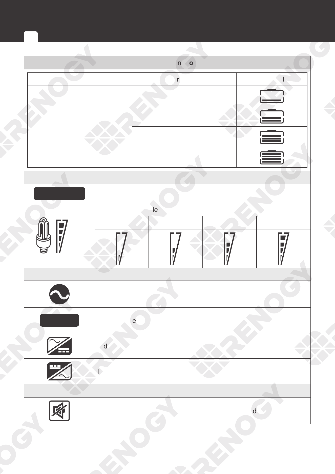
62
Operation
Icon Function Description
Load Percentage Battery Voltage LCD Display
Load < 20%
< 11.2V
11.2V - 11.7V
11.7V - 12.2V
> 12.2V
Load Information
OVER LOAD
Indicates overload.
100%
25%
Indicates the load level by 0-24%, 25-49%, 50-74%, and 75-100%.
0-24% 25-49% 50-74% 75-100%
Mode Operation Information
Indicates the inverter charger is connected to the shore power.
BYPASS
Indicates the load is supplied by the utility power.
Indicates the utility charger circuit is working.
Indicates the DC / AC inverter circuit is working.
Indicates the alarm of the inverter charger is disabled.
LCD Button Setting Battery Type User Mode
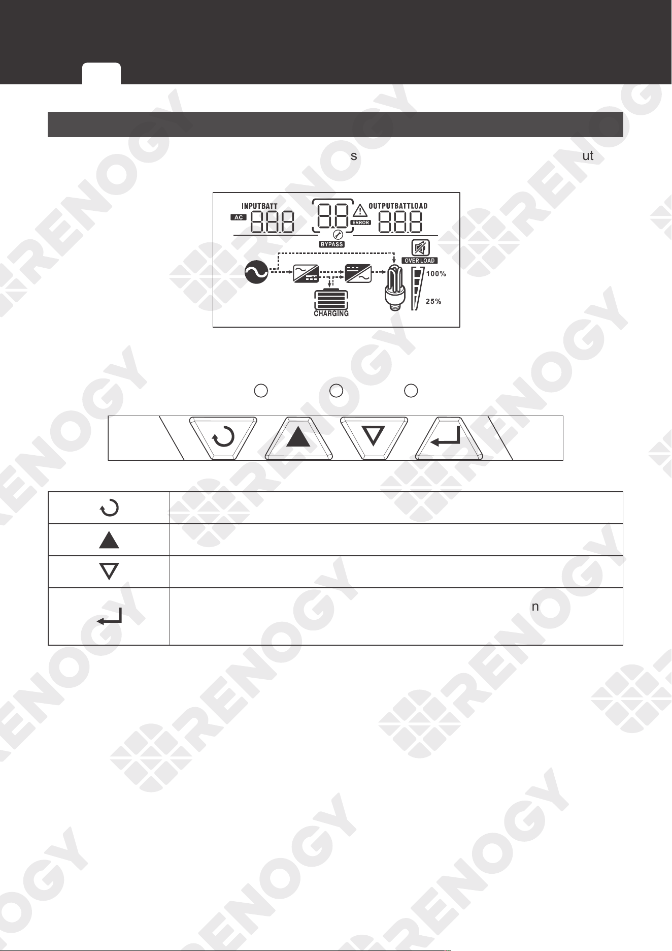
63
Operation
Button
You can turn to the display pages or set parameters of the inverter charger with the four buttons.
AC/INV CHG FAULT
KW
VA
Hz
%
KW
VA
Hz
C
%
Exit the settings and go back to the menu.
Menu key.
Menu key.
1. Long press the button to enter the parameter setting menu.
2. Short press to change / confirm setting in the parameter setting menu.
LCD Button Setting Battery Type User Mode
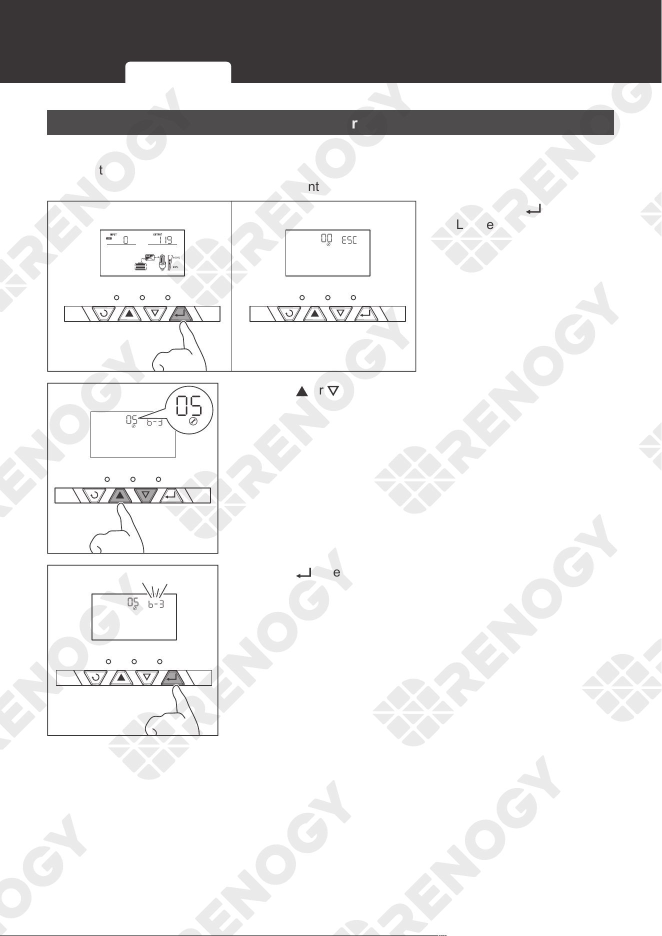
64
Operation
Setting Battery Type
Set the battery type immediately after the inverter charger is powered on. Refer to the
specifications provided by the battery manufacturer when choosing a preset battery. Damage
caused by incorrect battery type voids warranty.
AC/INV CHG FAULT
VV
AC/INV CHG FAULT
1. Long press until the
LCD enters setting mode.
AC/INV CHG FAULT
2. Press or to display Program 05.
AC/INV CHG FAULT
3. Press to enter 05 settings.
LCD Button Setting Battery Type User Mode
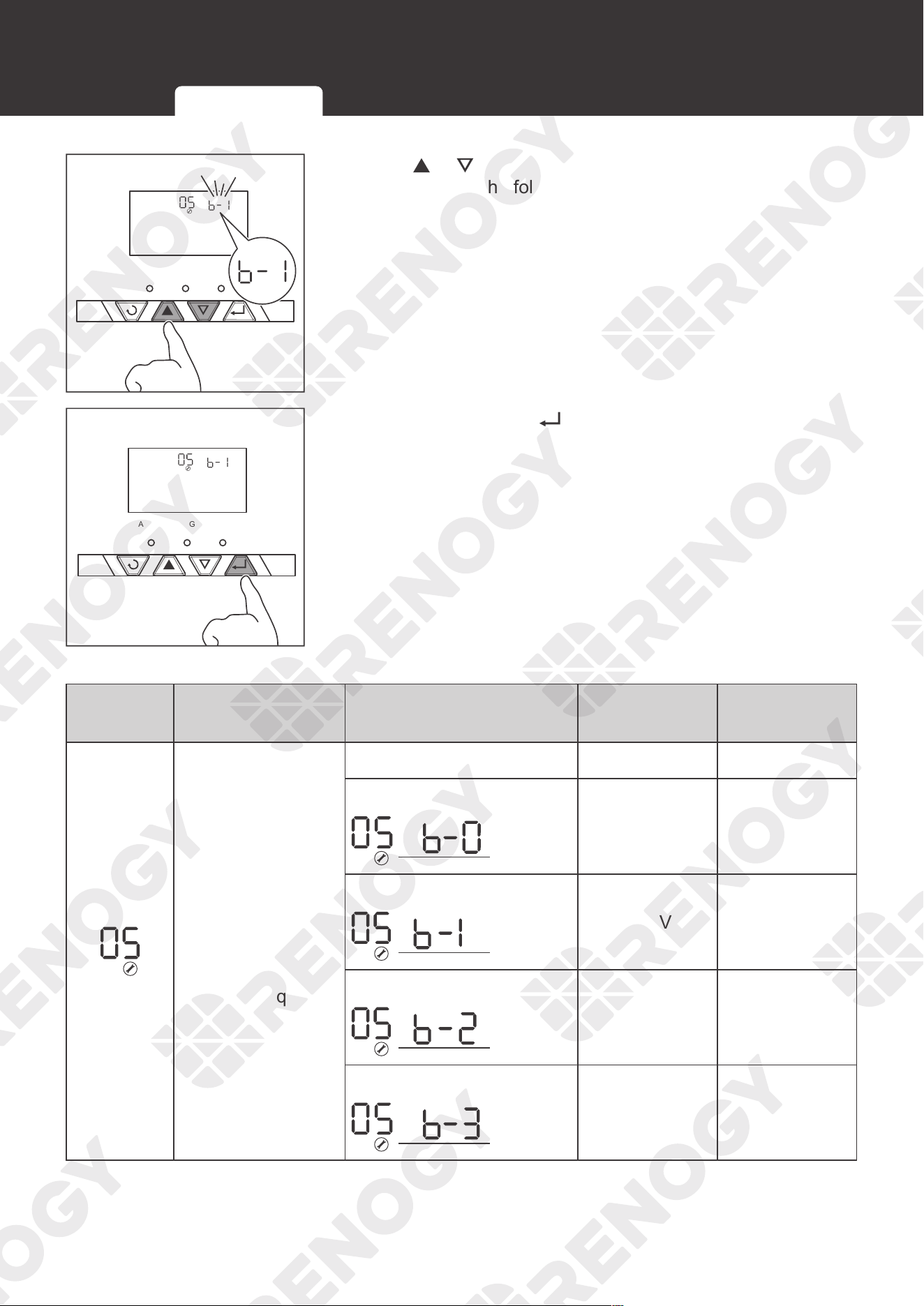
65
Operation
AC/INV CHG FAULT
4. Press or and select a battery type on demand in
accordance to the following table.
AC/INV CHG FAULT
5. After selection, press to save settings.
Program
Code
Description Parameter Setting Boost Voltage Float Voltage
For accurate
charging,
connection to
a temperature
sensor is required.
Type of battery
User Mode
— —
Gel 1
14.0V 13.7V
A.G.M.1
14.1V 13.4V
A.G.M.2
14.6V 13.7V
LCD Button Setting Battery Type User Mode
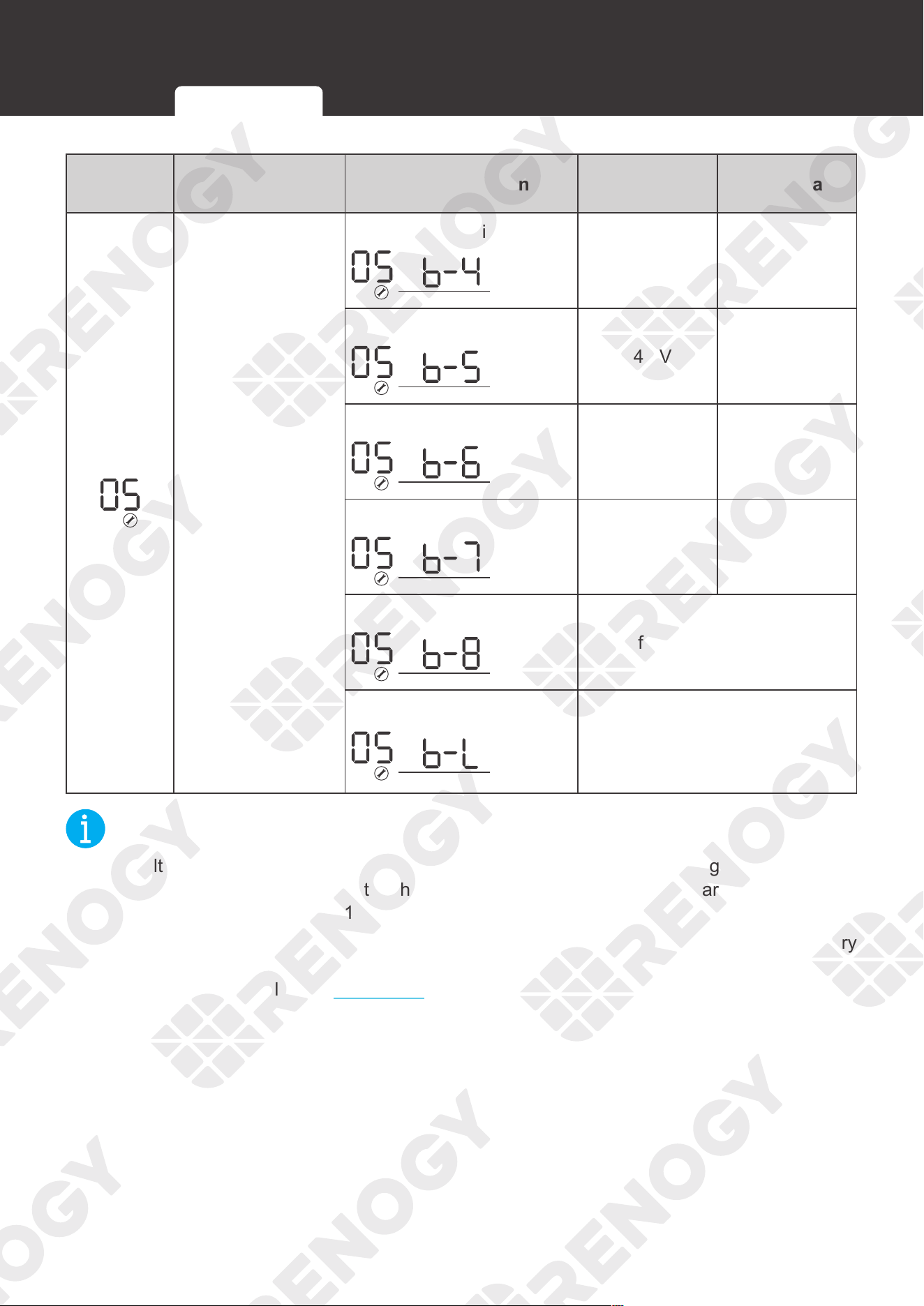
66
Operation
Program
Code
Description Parameter Setting Boost Voltage Float Voltage
For accurate
charging,
connection to
a temperature
sensor is required.
Sealed Lead Acid
14.4V 13.6V
Gel 2
14.4V 13.8V
Open Lead Acid / Flooded
14.8V 13.8V
Calcium
15.1V 13.6V
De-sulphation
15.5V for 4 hours
LI
When the voltage reaches
14.7V, the charging will stop.
When the voltage drops below
12.9V, the charging will resume.
NOT
E
z
The voltage of lithium charging is preset to 14.7V. When the charging voltage reaches the
preset threshold 14.7V, the inverter charger stops charging. It resumes charging when the
charging voltage drops below 12.9V.
z
If the preset battery parameters are not compatible with your system, you can set the battery
type to b-0 to enter the User mode. You can also use the DC Home app to customize the
parameters. For details, see User Mode below.
LCD Button Setting Battery Type User Mode
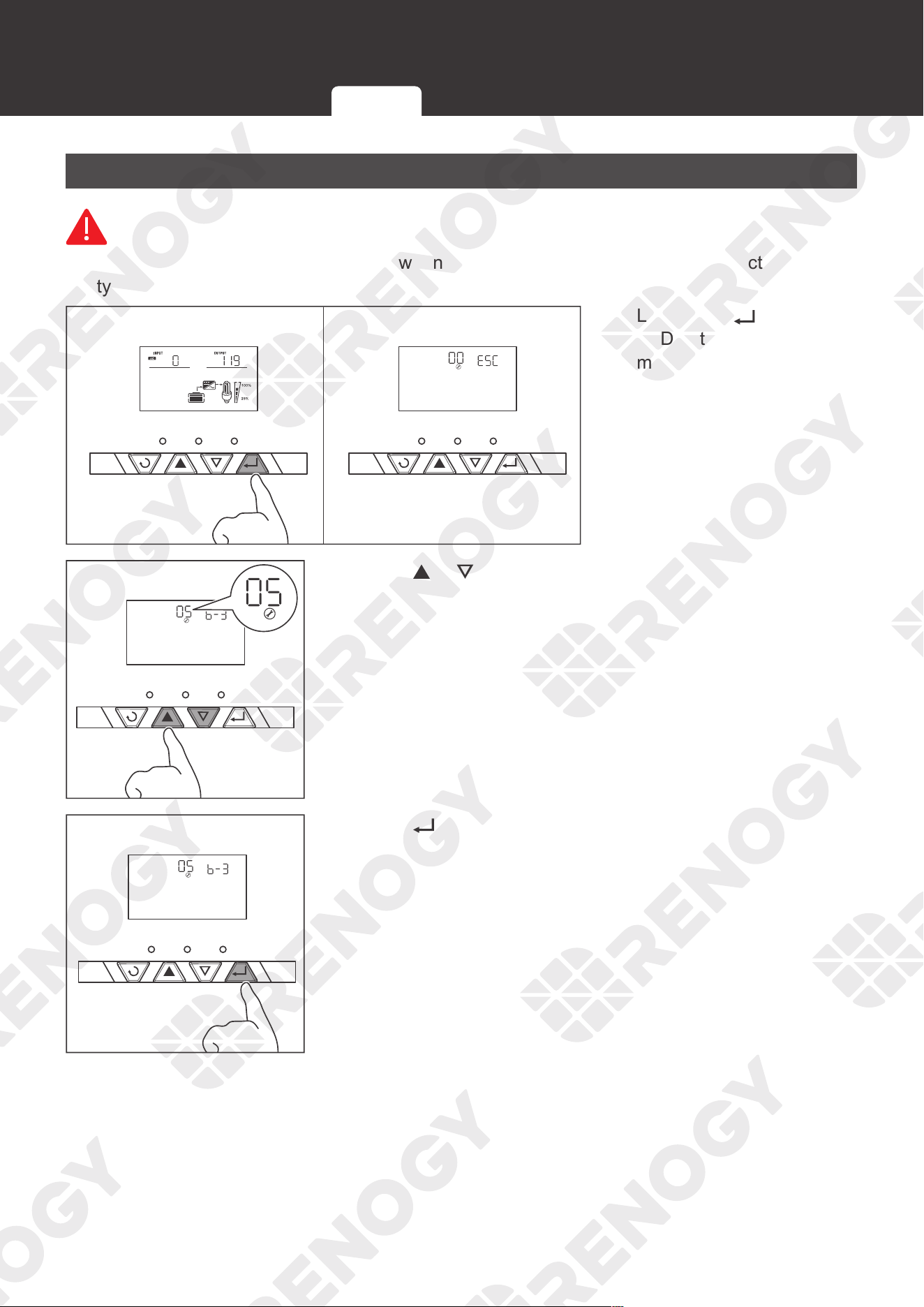
67
Operation
User Mode
WARNIN
G
z
Read the user manual of the battery when customizing a preset battery. Incorrect battery
type selection damages the inverter charger and voids the warranty.
AC/INV CHG FAULT
VV
AC/INV CHG FAULT
1. Long press until the
LCD enters the setting
mode.
AC/INV CHG FAULT
2. Press or until the LCD enters Program 05.
AC/INV CHG FAULT
3. Press to enter 05 settings.
LCD Button Setting Battery Type User Mode
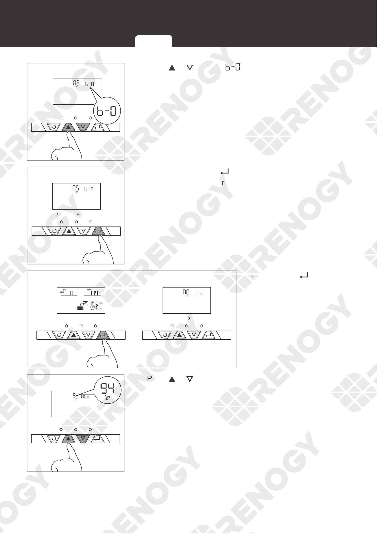
68
Operation
AC/INV CHG FAULT
4. Press or to select 。
AC/INV CHG FAULT
5. After selection, press to save settings.
By default, this inverter charger is preset to Boost at 14.3V
and Float at 13.7V.
AC/INV CHG FAULT
VV
AC/INV CHG FAULT
6. Long press until the
LCD enters the setting
mode.
AC/INV CHG FAULT
7. Press or to enter Program 94.
You can set the battery type in the user mode in Program
94.
LCD Button Setting Battery Type User Mode
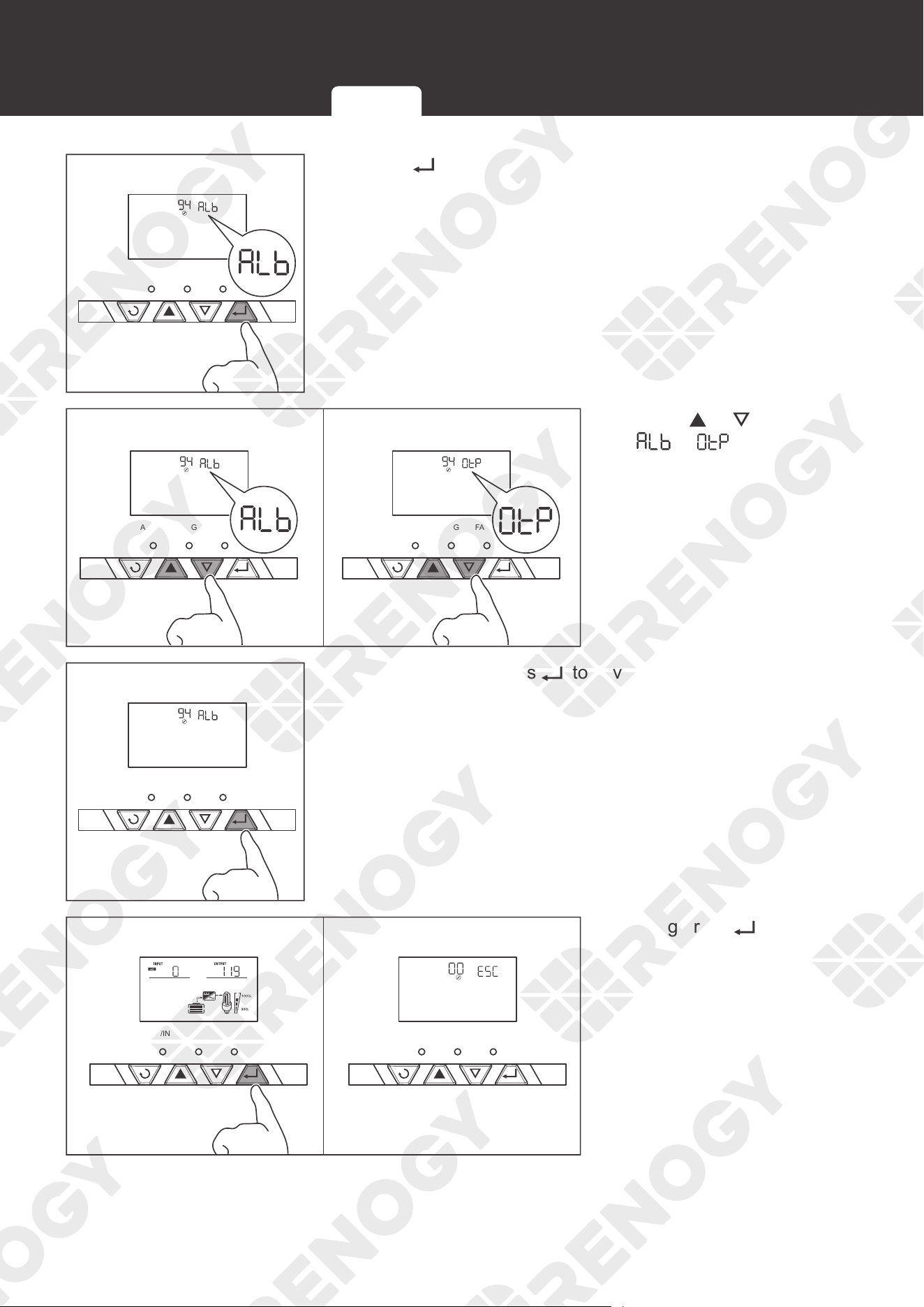
69
Operation
AC/INV CHG FAULT
8. Press to enter 94 settings.
Lithium Battery
Non-lithium Battery
AC/INV CHG FAULT AC/INV CHG FAULT
9. Press or to select
or according to
the battery type.
AC/INV CHG FAULT
10. After selection, Press to save settings.
AC/INV CHG FAULT
VV
AC/INV CHG FAULT
11. Long press until the
LCD enters the setting
mode.
LCD Button Setting Battery Type User Mode
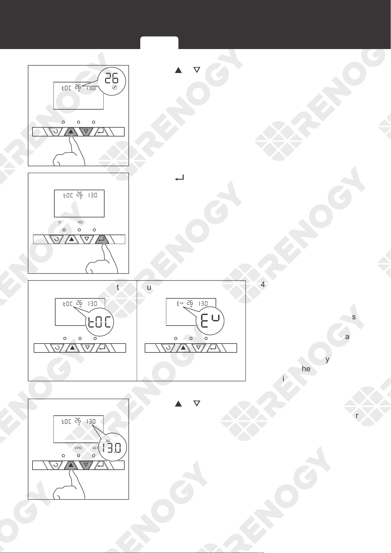
70
Operation
V
BATT
AC/INV CHG FAULT
12. Press or to enter Program 26.
AC/INV CHG FAULT
V
BATT
13. Press to enter 26 settings.
Maximum Charging Voltage Bulk Charging Voltage
AC/INV CHG FAULT AC/INV CHG FAULT
V
BATT
V
BATT
14. For lithium battery, set the
maximum charging voltage
in Program 26.
For non-lithium battery, set
the bulk charging voltage
(C.V voltage) in Program
26.
When the battery voltage
reaches the preset value,
the inverter charger will
stop charging the battery.
V
BATT
AC/INV CHG FAULT
V
BATT
15. Press or to set the voltage.
For lithium battery, set the voltage from 13.0V to 15.5V. For
non-lithium battery, set the voltage from 13.0V to 15.0V.
LCD Button Setting Battery Type User Mode
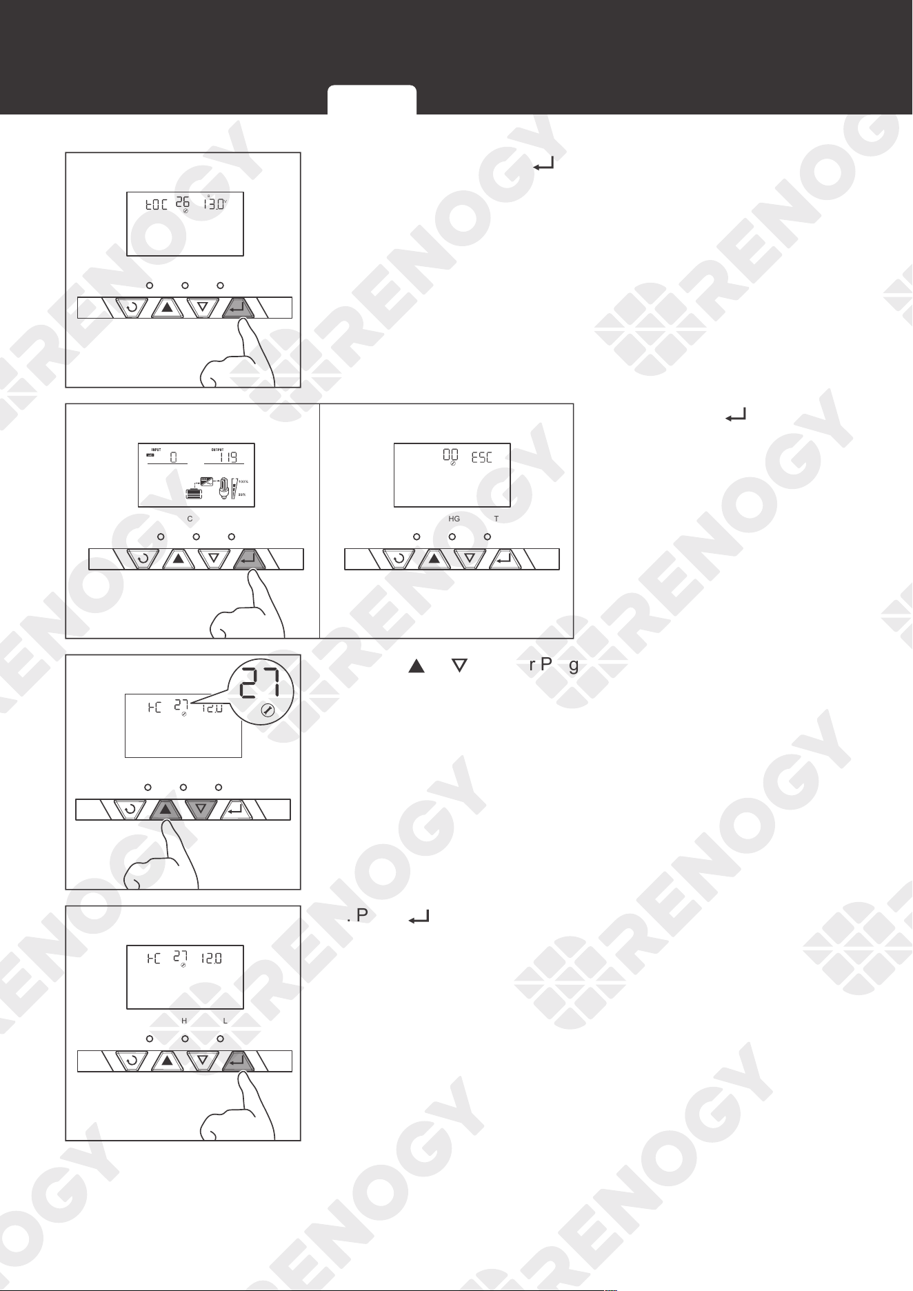
71
Operation
AC/INV CHG FAULT
V
BATT
16. After selection, press to save settings.
AC/INV CHG FAULT
VV
AC/INV CHG FAULT
17. Long press until the
LCD enters the setting
mode.
V
BATT
AC/INV CHG FAULT
18. Press or to enter Program 27.
V
BATT
AC/INV CHG FAULT
19. Press to enter 27 settings.
LCD Button Setting Battery Type User Mode
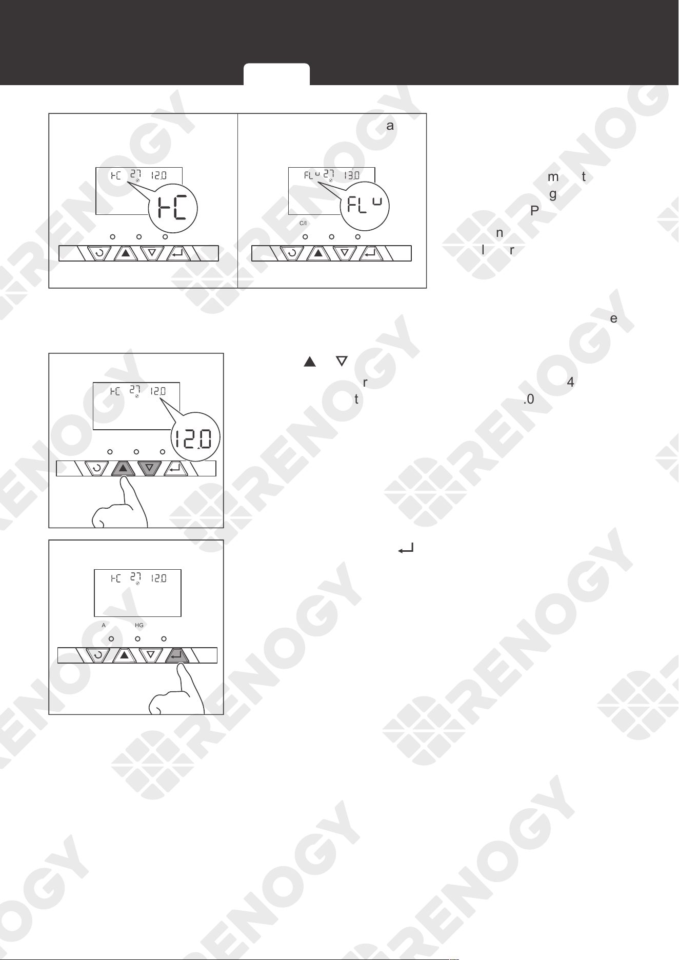
72
Operation
Battery Low Voltage Open
Charging
Floating Charging Voltage
AC/INV CHG FAULT AC/INV CHG FAULT
V
BATT
V
BATT
20. For lithium battery, set the
battery low voltage open
charging in Program 27.
For non-lithium battery,
set the floating charging
voltage in Program 27.
When the battery voltage
is lower than the preset
value, the inverter charger
starts to charge the battery
until the battery voltage
reaches the preset value
of Program 26.
AC/INV CHG FAULT
V
BATT
V
BATT
21. Press or to set the voltage.
For lithium battery, set the voltage from 12.0V to 14.0V. For
non-lithium battery, set the voltage from 13.0V to 15.0V.
AC/INV CHG FAULT
V
BATT
22. After selection, Press to save settings.
LCD Button Setting Battery Type User Mode
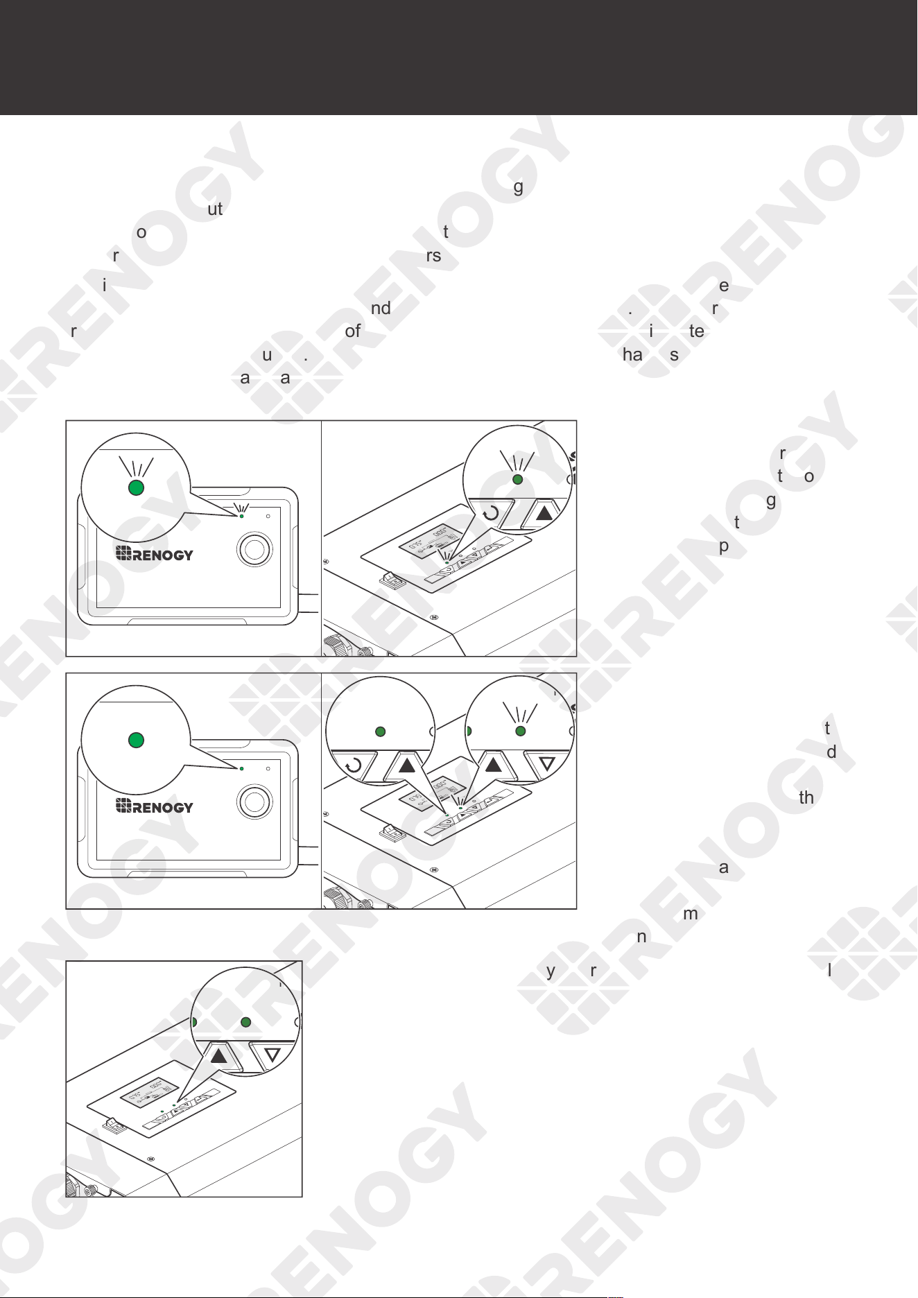
73
Working
Working
REGO 12V 3000W Inverter Charger combines an inverter charger with an automatic transfer
switch into one complete system. Featuring a three-stage battery charging mode when
connected to the utility AC input, the inverter charger can meet powerful needs as well as
charge your battery bank. As a power supply, it is capable of producing cleaner, smoother, and
more reliable electricity to address your diverse needs.
The inverter charger is equipped with a 30A transfer relay switch that switches between the
charging and the standby mode depending on availability of AC input. If AC is present, the
transfer relay bypasses up to 30A of the incoming AC input through the inverter to power the AC
loads on the invert
er’s
output. Simultaneously, the inverter charger charges the battery up to 75
Amps. In the event that charger charges the battery up to 75 Amps will power the loads through
the battery bank.
ON ERR
RMS-P2
ON ERR
AC / INV
CHC
OFF
ON
FAULT
ARNING
Pure Sine Wave Inverter Charger
CHARGING
LI
OUTPUTBATT
INPUTBATT
100%
25%
BYPASS
AC/INV CHG
1. The ON indicator of the
wired remote control and
the AC/INV indicator of
the inverter charger flash
green when the inverter
charger is powering loads
from the battery.
ON ERR
RMS-P2
ON ERR
AC / INV
CHC
OFF
ON
FAULT
ARNING
Pure Sine Wave Inverter Charger
CHARGING
LI
OUTPUTBATT
INPUTBATT
100%
25%
BYPASS
AC/INV CHG FAULT
AC/INV CHG FAULT
2. The ON indicator of the
wired remote control and
the AC/INV indicator of the
inverter charger are solid
green when the inverter
charger is powering the
loads through an AC Input
Source, and when the
inverter charger starts
to charge the battery at
the same time. The CHG
indicator flashes green.
AC / INV
CHC
FAULT
ARNING
High voltage,in order to avoid risks,
Pure Sine Wave Inverter Charger
CHARGING
LI
OUTPUTBATT
INPUTBATT
100%
25%
BYPASS
AC/INV CHG FAULT
OFF
ON
3. When the battery is fully charged, the CHG indicator is solid
green.
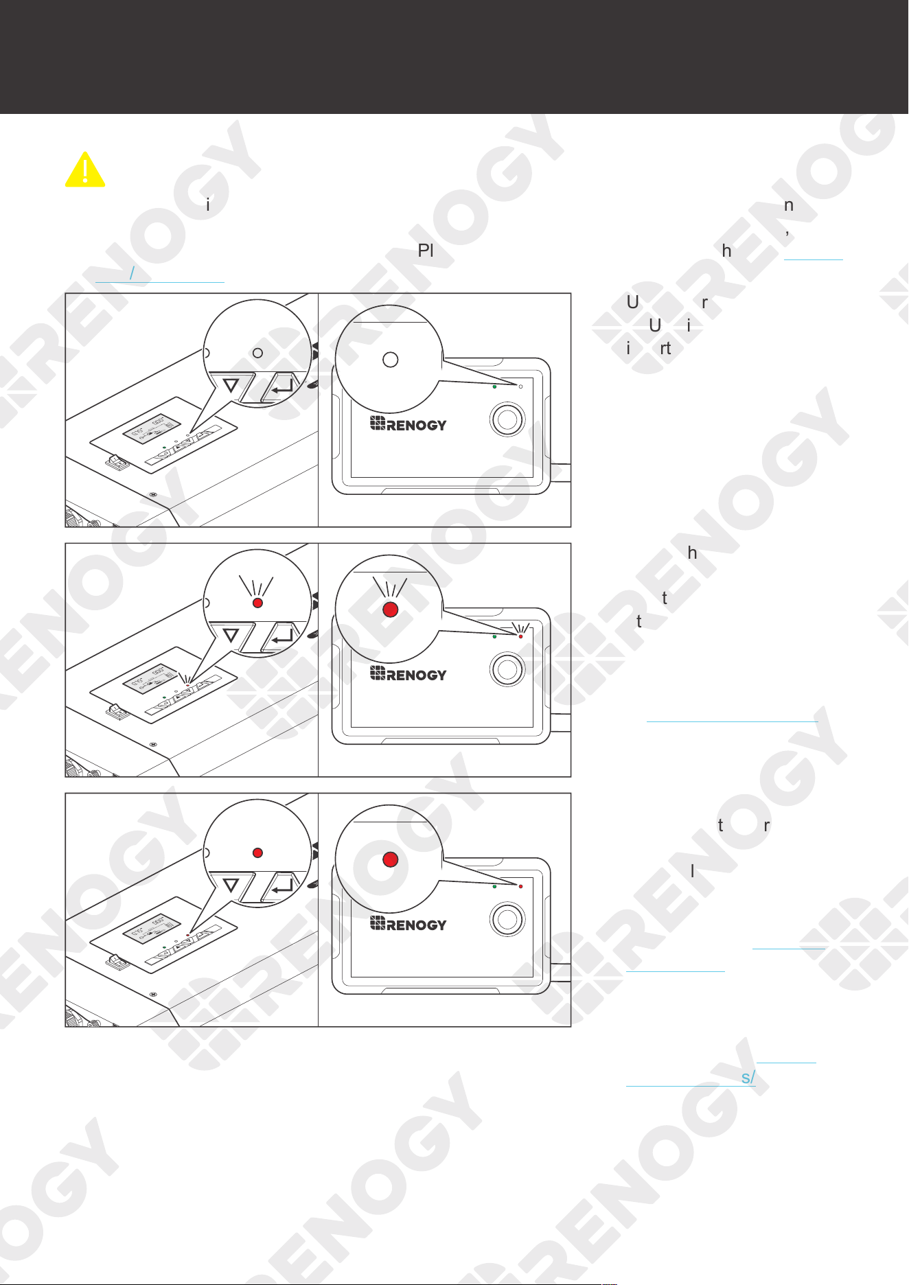
74
Working
CAUTIO
N
z
If the AC/INV indicator and CHG indicator do not light up as described in this user manual,
but the power supply equipment (batteries and AC input source) is operating normally, the
inverter charger needs troubleshooting. Please contact our customer service through renogy.
com/contact-us/.
ON ERR
RMS-P2
ON ERR
AC / INV
CHC
FAULT
ARNING
Pure Sine Wave Inverter Charger
CHARGING
LI
OUTPUTBATT
INPUTBATT
100%
25%
BYPASS
AC/INV CHG FAULT
OFF
ON
4. Under normal conditions,
FAULT indicator of the
inverter charger and the
ERR indicator of the wired
remote control will not light
up.
ON ERR
RMS-P2
ON ERR
AC / INV
CHC
FAULT
ARNING
Pure Sine Wave Inverter Charger
CHARGING
LI
OUTPUTBATT
INPUTBATT
100%
25%
BYPASS
AC/INV CHG FAULT
OFF
ON
5. If both the FAULT and
ERR indicators flash red,
and the buzzer sounds
at the same time (0.5s),
it means warnings are
provided by the inverter
charger. For details, refer
to Warning/Fault Codes in
this user manual.
ON ERR
RMS-P2
ON ERR
AC / INV
CHC
FAULT
ARNING
Pure Sine Wave Inverter Charger
CHARGING
LI
OUTPUTBATT
INPUTBATT
100%
25%
BYPASS
AC/INV CHG FAULT
OFF
ON
6. If both the FAULT and
ERR indicators are always
in red, and the buzzer
sounds long, it means
that the inverter charger
needs troubleshooting. For
details, refer to Warning/
Fault Codes in this
user manual. For more
technical instructions,
contact our customer
service through renogy.
com/contact-us/.
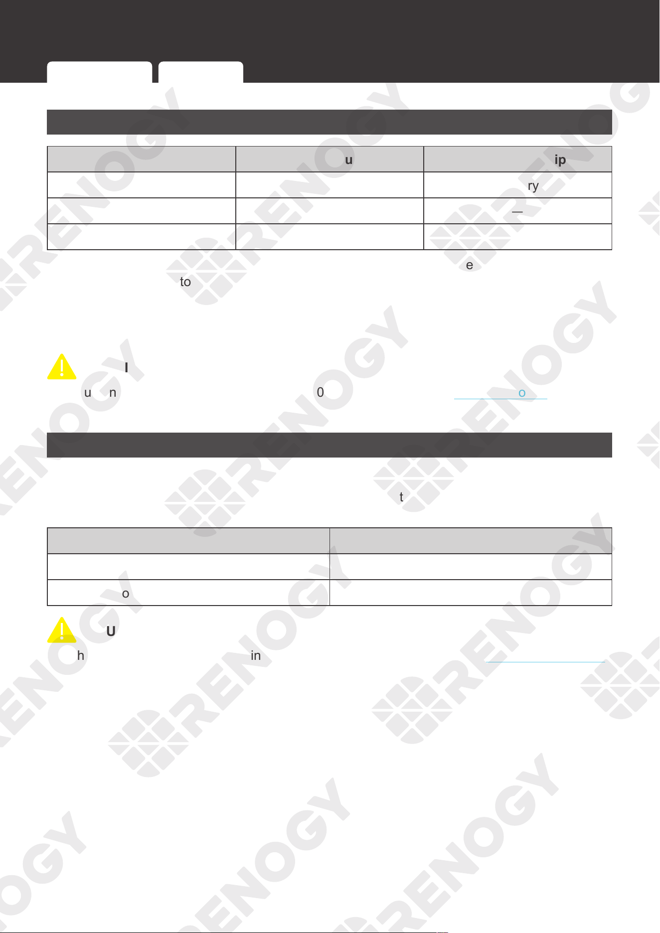
75
Working Logic
Working Logic
Power Supply Logic
Battery Voltage AC Input Power Supply Equipment
10.5V to 16V (
±
0.3V) OFF Battery
< 10.5V (
±
0.3V) OFF —
— ON AC Input
If the inverter charger is connected to the battery or the AC input is powered off, the battery
starts to supply power to the load when the battery voltage ranges from 10.5V to 16V (
±
0.3V). If
the battery voltage is less than 10.5V (
±
0.3V), the battery stops supplying power to the load.
If the inverter charger has been connected to the AC input and is in the power supply state, the
AC input starts to supply power to the load.
CAUTIO
N
z
You can set the output priority in Program 01. For details, refer to Program Codes in this
user manual.
Charging Logic
█
Working conditions
If the inverter charger is connected to the AC input and is in the power supply state, the inverter
charger will automatically recognize the battery voltage and charge the battery.
Battery Voltage Charging Status
Less than the preset value Start charging
Equal to or greater than the preset value Stop charging
CAUTIO
N
z
The preset value varies according to battery types. For details, refer to Setting Battery Type
in this manual.
Power Supply Logic Charging Logic Heat Dissipation Logic
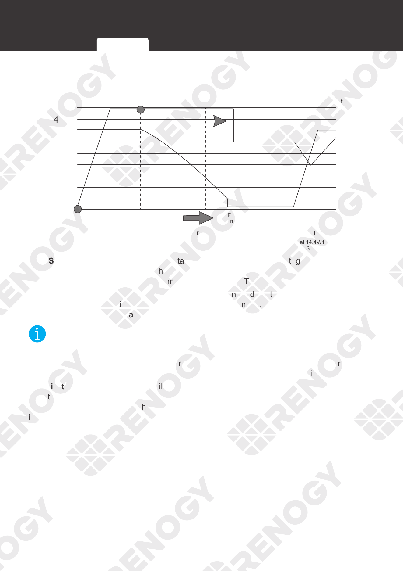
76
Working Logic
█
Battery Charging Stages
1
1
2
2
3
3
4
4
Time
Float 13.5v
100
50
0
10.5
11
11.5
12
12.5
13
13.5
14
14.5
15
Adjustable Time Depending on
Battery Bank Size
Full Current Available on Float for
on Board Supply in Power Pack Mode
Step 2 = Absorption Charge at 14.4V/14.8V
Step 4 = Low Voltage Reset to Step 1
Step 1 = Constant Current Charge
The New Battery Chargers And Boosters Offer The Fastest Charge Rate Currently Available
Step 3 = Constant Voltage at 13.5V
Charging
Current %
Volts
Bulk Stage: The charger will supply constant current until the battery voltage reaches the boost
voltage. The software will calculate the time to start charging until the battery voltage drops
below the boost voltage of 0.3V. This time is referred as T0. T0 x 10 = T1.
Boost Stage: The charger will supply constant voltage and reduce the current slowly through
this stage. The charger will stay in this stage until T1 has run out. After this time the charger will
enter the float stage. This stage will last between 1 hour and 12 hours depending on T1.
NOT
E
z
The stage is determined by internal software in the inverter charger.
Float Stage: During this stage the charger will supply a constant voltage which is determined by
the battery selected and will keep current at a minimum. This stage acts as a trickle charger.
Equalization: This stage is only available for batteries with equalization, such as flooded. During
this stage the batteries are charged at a higher voltage than normal and for most batteries this
could cause damage. Refer to the user manual of the battery or contact the manufacturer to see
if this stage is needed.
Power Supply Logic Charging Logic Heat Dissipation Logic
77
Working Logic
Heat Dissipation Logic
The inverter charger uses the fan for heat dissipation. The working logic of the fan is as follows:
Inverter Charger Fan
Working properly The fan works for 1 minute every 30 minutes.
AC output current
When AC output current ≥ 35% of rated current of the AC load,
the fan starts working.
When AC output current < 35% of rated current of the AC load,
the fan stops working.
DC input current
When DC input current ≥ 10A, the fan starts working.
When DC input current < 10A, the fan stops working.
Temperature
When the temperature of the inverter charger ≥ 50
°C
, the fan
starts working.
When the temperature of the inverter charger < 50
°C
, the fan
stops working.
Power Supply Logic Charging Logic Heat Dissipation Logic

78
Power off
Power off
Main Switch
AC / INV
CHC
OFF
ON
FAULT
ARNING
please read the instructions carefully
Before working on this product.
High voltage,in order to avoid risks,
Pure Sine Wave Inverter Charger
AC / INV
OFF
ON
1. Press the main switch of
the inverter charger to
"OFF" to turn it off.
AC / INV
CHC
OFF
ON
FAULT
2. The LCD and the LED indicators go out when the inverter
charger is powered off.
Wired Remote Control
ON ERR
RMS-P2
1. When using a wired remote control, press the button on the
wired remote control to turn off the power.
Main Switch Wired Remote Control
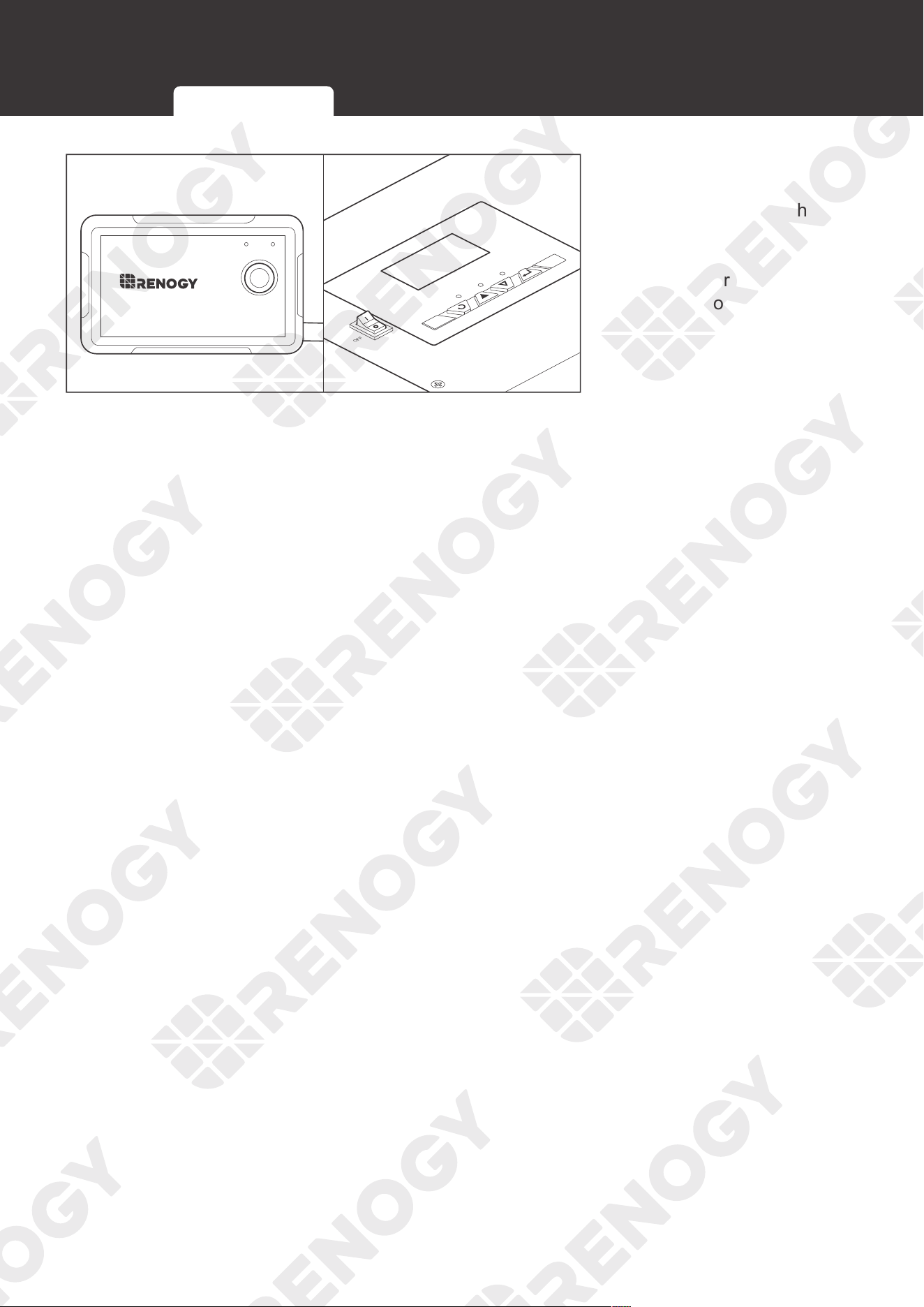
79
Power off
AC / INV
CHC
OFF
ON
FAULT
ON ERR
RMS-P2
2. The LCD and LED
indicators of the inverter
charger as well as the
ON indicator of the wired
remote control go off when
the inverter charger is
powered off.
Main Switch Wired Remote Control
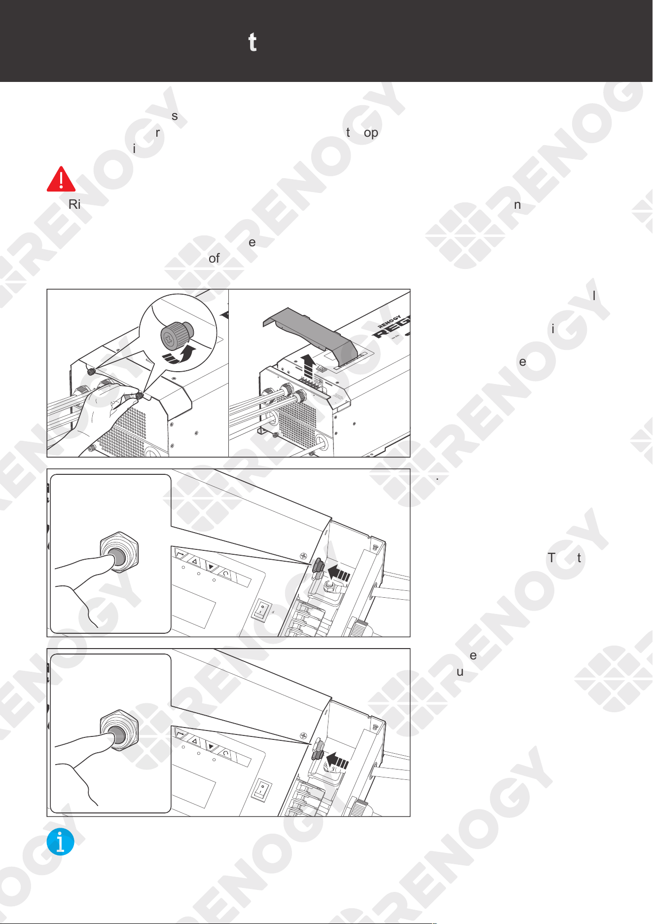
80
Overcurrent Protection
Overcurrent Protection
The inverter charger is integrated with two circuit breakers which ensure that the inverter
charger keeps operating even when the input/output stops working. When the input/output
circuit breaker is activated, a manual reset is required to resume operation.
WARNIN
G
z
Risk of electric shock! Turn off the inverter charger and the power devices connected to it
when the circuit breaker is reset.
z
Wear proper protective equipment and use insulated tools during operation. Be careful when
touching bare terminals of capacitors as they may retain high lethal voltages even after the
power is removed.
AC / INV
CHC
FAULT
Pure Sine Wave Inverter Charger
REMOTE
DRY
CAN
NO
NC
C
CONTACT
CHARCER W
PROT
WARNING
please read the instructions carefully
Before working on this product.
High voltage,in order to avoid risks,
L
L
N
OUTPUT
INPUT
N
NEGATIVE
WARNING
please read the instructions carefully
Before working on this product.
High voltage,in order to avoid risks,
AC / INV
CHC
OFF
ON
FAULT
Pure Sine Wave Inverter Charger
REMOTE
DRY
CAN
NO
NC
C
CONTACT
CHARCER W
PROT
WARNING
please read the instructions carefully
Before working on this product.
High voltage,in order to avoid risks,
L
L
N
OUTPUT
INPUT
N
NEGATIVE
WARNING
please read the instructions carefully
Before working on this product.
High voltage,in order to avoid risks,
ON
ARNING
High voltage,in order to avoid risks,
OFF
ON
1. Turn the two upper panel
screws counterclockwise
by hand or a Phillips
screwdriver, and remove
the Top Plate.
AC/INV
ON
OFF
CHG
FAULT
WARN ING
please read the instructions carefully
Before working on this product.
High voltage,in order to avoid risks,
WARNING
please read the instructions carefully
Before working on this product.
High voltage,in order to avoid risks,
CHARGER INPUT
PROTECT
INVERTER OUTPUT
PROTECT
CHARGER INPUT
PROTECT
2. When the AC input
current exceeds 40A, the
Input Circuit Breaker will
automatically pop out.
Press the CHARGER
INPUT PROTECT button
to reset the circuit breaker.
AC/INV
ON
OFF
CHG
FAULT
WARNING
please read the instructions carefully
Before working on this product.
High voltage,in order to avoid risks,
WARNING
please read the instructions carefully
Before working on this product.
High voltage,in order to avoid risks,
CHARGER INPUT
PROTECT
INVERTER OUTPUT
PROTECT
INVERTER OUTPUT
PROTECT
3. When the AC output
current exceeds 30A, the
Output Circuit Breaker
will automatically pop out.
Press the INVERTER
OUTPUT PROTECT
button to reset the circuit
breaker.
NOT
E
z
After resetting, install the Top Plate back to the inverter charger.
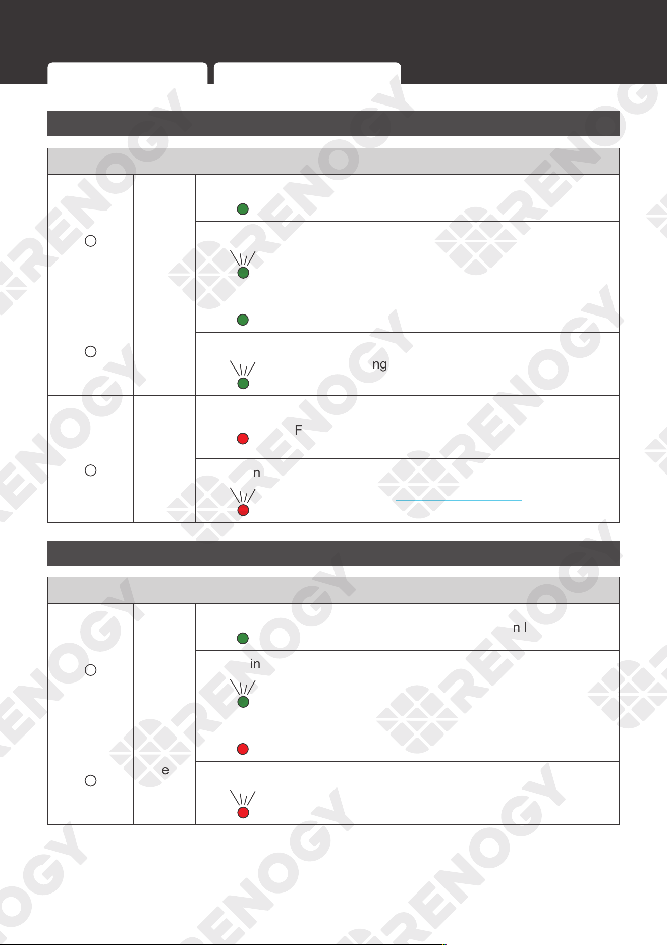
81
LED Indicators
LED Indicators
Indicator of the Inverter Charger
LED Indicator Parameter
AC/INV
Green
Solid
Output is powered by an AC source in line mode.
Flashing
Output is powered by battery or in invert mode.
CHG
Green
Solid
Battery is fully charged.
Flashing
Battery is being charged.
FAULT
Red
Solid
Fault
For details, read Warning/Fault Codes in the user
manual.
Flashing
Warning
For details, read Warning/Fault Codes in the user
manual.
Indicator of the Wired Remote Control
LED Indicator Parameter
ON
Green
Solid
Output is powered by an AC source in line mode.
Flashing
Output is powered by battery or in invert mode.
ERR
Red
Solid
Fault
Flashing
Warning
Indicator of the Inverter Charger Indicator of the Wired Remote Control
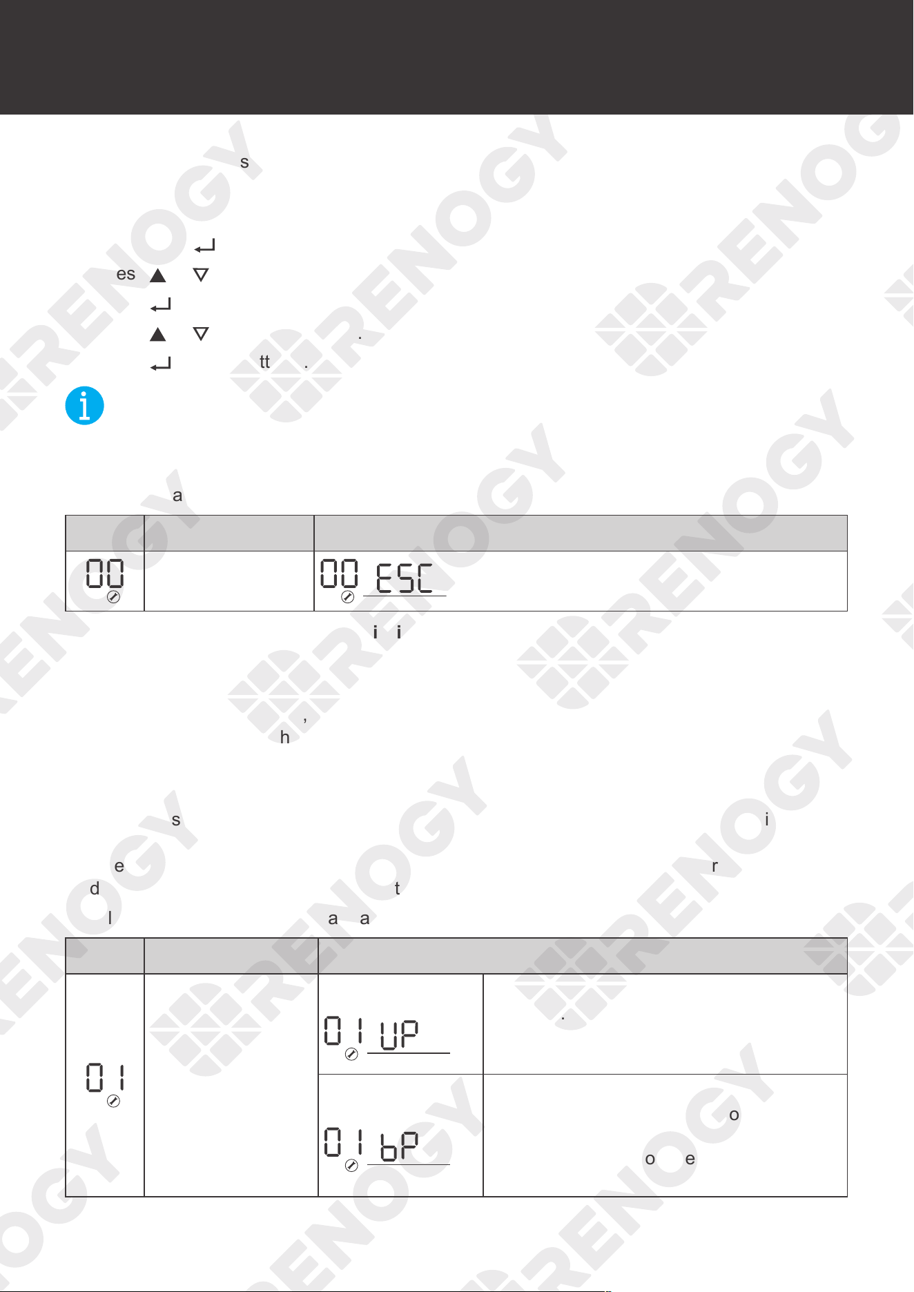
82
Program Codes
Program Codes
The inverter charger is fully programmable. You may change the respective parameter by going
to the Program Code listed below.
█
Operation Methods
(1). Long press
until the LCD enters the setting mode.
(2). Press
or to select programs.
(3). Press
to enter settings.
(4). Press
or to set parameters.
(5). Press
to save settings.
NOT
E
z
Restarting the inverter controller is required if changes are made to frequency, output
voltage, charging current, and AC input voltage.
Setting Programs:
Icon Description Details
Exit setting mode Escape
█
01 Utility Priority and Battery Priority
Utility Priority
The default setting is Utility Priority (Ut1). Under this setting, once the inverter charger is
connected to the utility power, it will power the loads using the electricity from shore supply. The
inverter charger will start charging the battery bank using the AC source, if necessary
. In case of
power outage, the system automatically switches to battery-powered mode.
Battery Priority
The optional setting is Battery Priority (SbU). Under this setting, the inverter charger will provide
power using the connected battery bank even when it detects an AC source. When the battery
voltage reaches the low voltage setting point in Program 12, the inverter charger will power the
loads using the connected AC source but will not charge the battery bank.
Detailed settings of Program 01 are as follows:
Icon Description Details
Output source
priority for the load
Utility Priority
Utility is the preferred power source
for loads. Battery will provide power to
the loads only when utility power is not
available.
Battery priority
Battery is the preferred power source for
loads. Utility provides power to the loads
only when battery voltage drops to either
low-level warning voltage or the setting
point in Program 12.
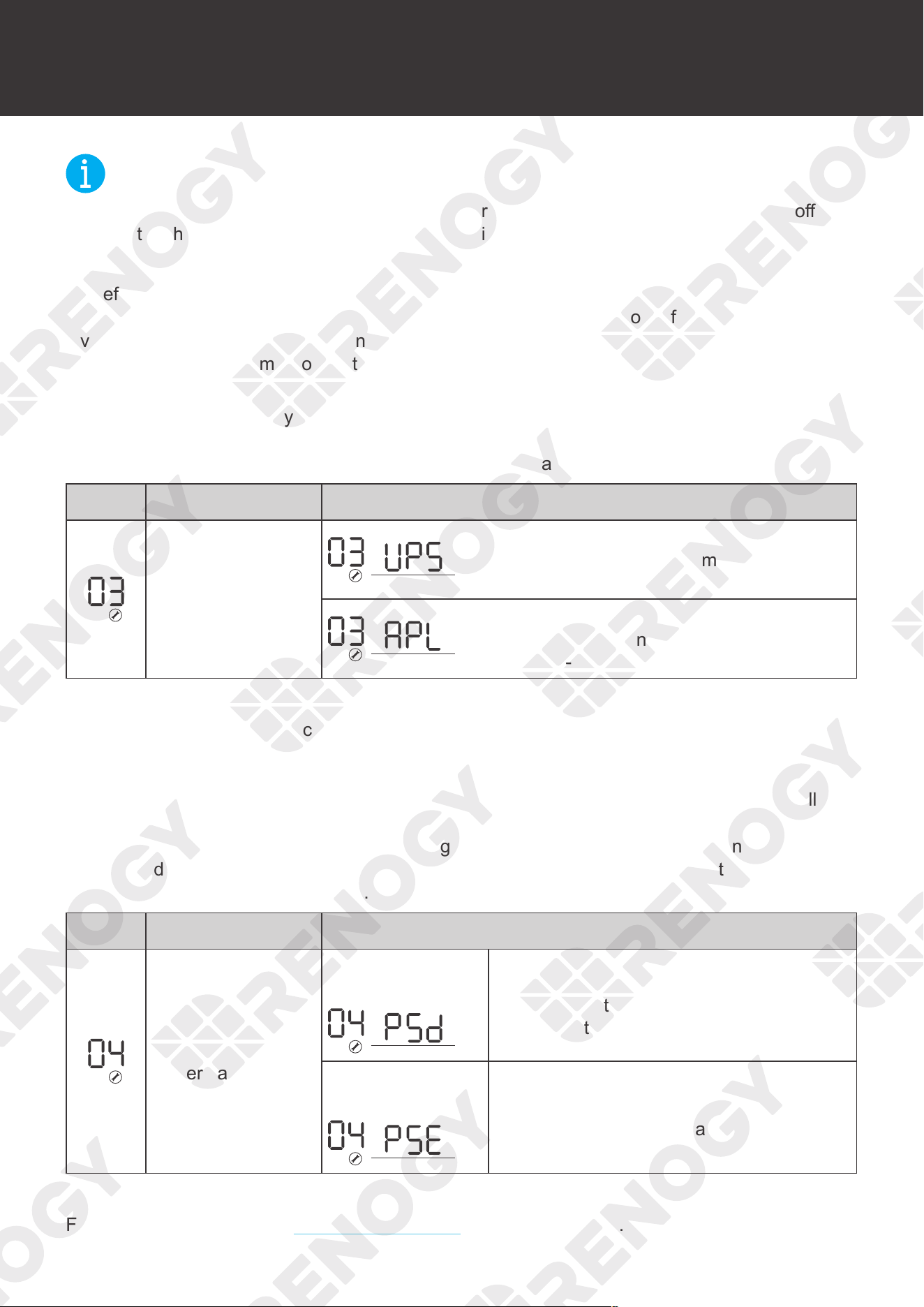
83
Program Codes
NOT
E
z
After settings, disconnect the inverter charger from the AC source/shore power. Turn off the
inverter charger and wait for 10 seconds. Turn it on and settings will take effect.
█
03 AC Input Voltage Range
By default, the inverter charger is set to a narrow input voltage range for which the inverter
charger will work in Utility mode. It is recommended to keep in this mode if connecting the
inverter charger to sensitive electronic devices such as computers and TVs as the narrow mode
reduces the switching time from external power to battery.
Selecting a wide input voltage range is recommended when you need power and might be
running a generator as they tend to have wider tolerance for a disturbed waveform or are having
issues with the stability of the main utility line. This will have a wider range to prevent switching
to backup battery mode if utility power is within the wider range.
Icon Description Details
Input voltage range
Wide
Utility effective range: Nominal output
voltage: -23% to +15%
Narrow (default)
Utility effective range: Nominal output
voltage: -15% to +15%
█
04 Power Saving Mode
Power saving is designed to conserve battery power when AC input is not or rarely required by
the loads. In this mode, the inverter charger pulses the AC output looking for an AC load (i.e.,
appliance). Whenever an AC load (greater than 50 watts) is turned on, the inverter charger
recognizes the need for power and automatically starts inverting, and the output goes to full
voltage. When there is no load (or less than 50 watts) detected, the inverter automatically
goes back into search mode to minimize energy consumption from the battery bank. In Power
Saving Mode, the inverter charger will draw power mainly in sensing moments, thus the idle
consumption is significantly reduced.
Icon Description Details
Enable or disable
power saving mode
Saving mode
disabled (default)
If the power saving mode is disabled,
the output of the inverter charger will be
available at all times.
Saving mode
enabled
If the power saving mode is enabled,
the output of the inverter charger will be
off until a load greater than 50 watts is
detected.
█
05 Setting battery Type
For more instructions, read Setting Battery Type in the user manual.
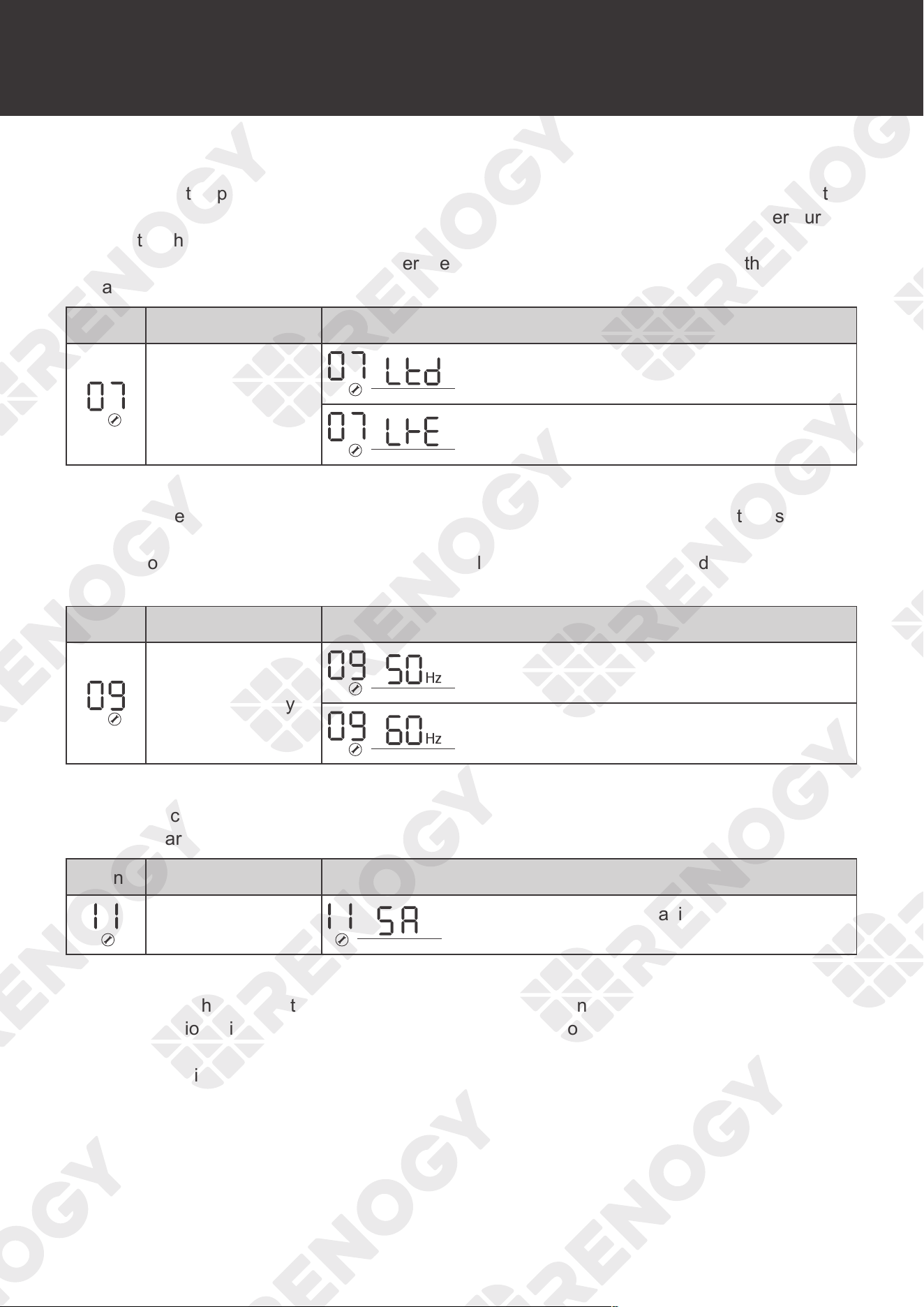
84
Program Codes
█
07 Auto Restart Temperature Fault
The operating temperature range for the inverter charger is 32
°
F to 104
°
F or 0
°
C to 40
°
C. If the
temperatures of internal power components begin to exceed their safe operating temperature,
the inverter charger shuts down to protect itself from damage. This setting controls whether the
inverter charger automatically restarts after the inverter charger cools down or whether you have
to manually restart the inverter charger.
Icon Description Details
Auto restart upon
overtemperature
Restart disabled (default)
Restart enabled
█
09 Output Frequency
The factory default frequency for the inverter charger is 60 Hz. Normally, manufacturers build
electrical devices for a certain amount of Current, Voltage and Hertz (Cycles) as shown in the
specifications. The Current is dependent of the Voltage and the Hertz supplied to an electric
motor or appliance.
Icon Description Details
Output frequency
50 Hz
60 Hz (default)
█
11 Maximum Utility Charging
The inverter charger can operate like the battery charger, converting the incoming AC input into
the DC recharging power.
Icon Description Details
Maximum utility
charging current
The default is the maximum value
(75A-3KW), with a 5A minimum.
█
12 Low Battery Voltage Setpoint
The purpose of this setpoint is to protect the batteries from being overdischarged. It assumes
that Battery Priority is set on Program 01. When the battery voltage reaches the preset value
in Program 12, the inverter charger will stop supplying power to loads. Once the utility power is
detected, the utility power/generator will supply power to the loads.
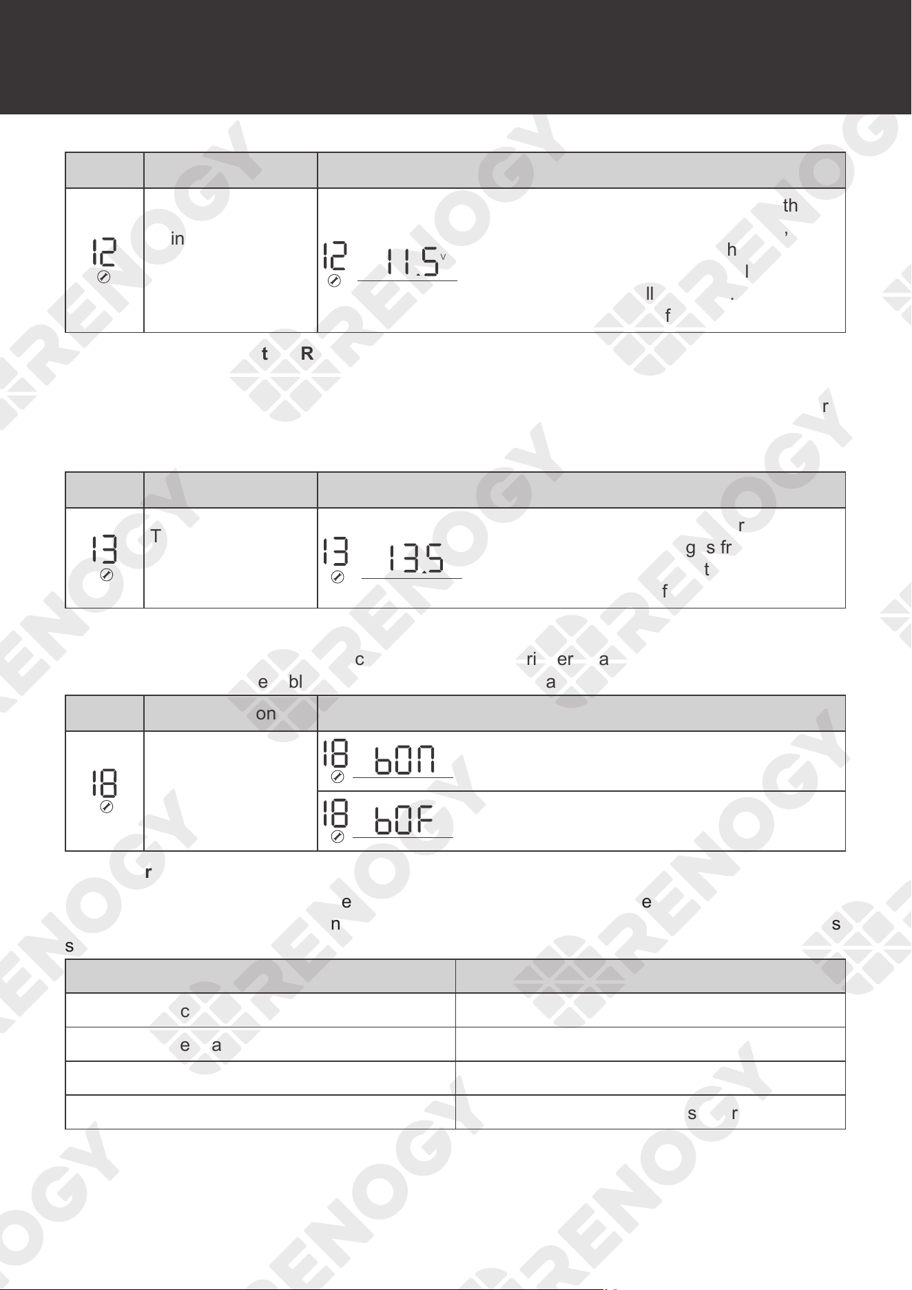
85
Program Codes
Icon Description Details
Low battery voltage
point when the
power source
switches from
battery to utility
V
BATT
The range is from 10.5V to 12.5V. If the
battery voltage is below this setpoint, no
power is given to loads from the battery. By
default this is the low battery voltage in the
charging table for all batteries. Increment
of each press is 0.1V for 12V.
█
13 Overvoltage Battery Recovery
This setpoint indicates that the voltage returns to normal value when a battery has been
overcharged or is over the voltage limit. The inverter charger will be in a fault state if the battery
voltage is above this designated setpoint and resume normal battery operation when reaching
this setpoint.
Icon Description Details
Threshold to trigger
overvoltage battery
recovery
V
BATT
Range: 13.0V and 15.5V. Otherwise,
the output of bypass ranges from 13.0V
to 15.5V. The voltage is set by you on
demand. Increment of each press is 0.1V.
█
18 Alarm Control / Behavior
When a fault occurs on the inverter charger, an alarm is triggered and the inverter charger and
stops working. You can enable or disable the alarm on demand.
Icon Description Details
Beeps while
function keys are
pressed
Alarm on (default)
Alarm off
Alarm Parameters:
The buzzer beeps when the inverter charger encounters any of the following: low voltage
shutdown, high voltage shutdown, overheating protection, and overload protection. For details,
see the table below:
Action & Alarm Buzzer
Pressing Function Keys The buzzer will beep for 0.5s
Working Mode Transfer The buzzer will beep for 0.5s
Overheating / Overload Alarm The buzzer will beep for 0.3s every 1s
Low-voltage / High-voltage Alarm The buzzer will beep for 0.2s every 0.5s
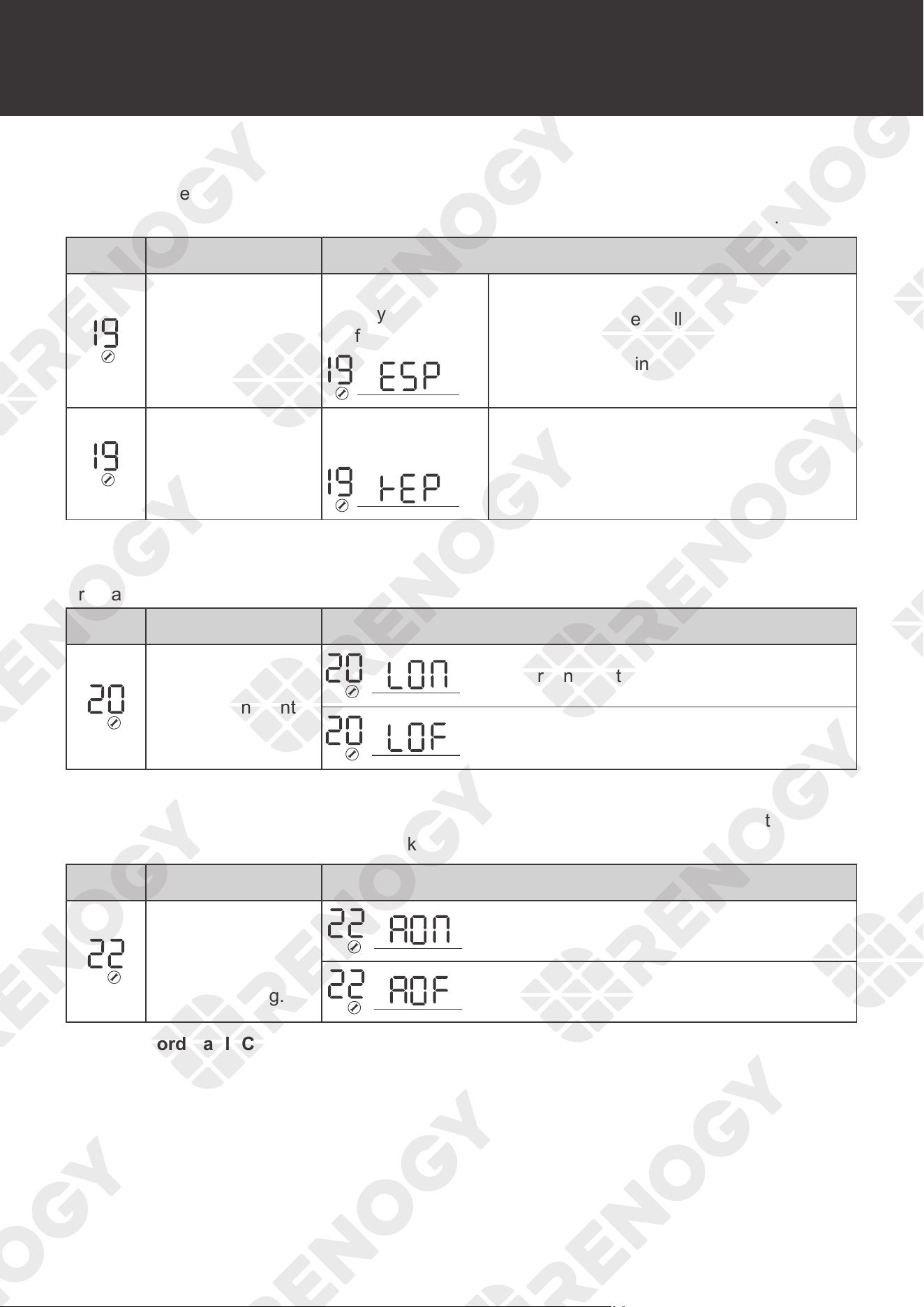
86
Program Codes
█
19 Screen Mode
By default, after 1 minute of inactivity, the inverter charger will return to the screen displayed at
startup. You can change this mode to continue viewing the last screen before inactivity.
Icon Description Details
Auto return to
default display
screen
Return to default
display screen
(default)
The display screen will return to default
screen (Input voltage / Output voltage)
after 1 minute of inactivity.
Auto return to
default display
screen
Stay at latest
screen
Display screen will stay on current screen
until you change it.
█
20 LCD Screen Mode
The LCD on the inverter charger will always stay on by default. Y
ou can change the mode in
Program 20.
Icon Description Details
LCD Screen Control
LCD screen will stay on (default)
LCD screen will turn off after inactivity.
█
22 Normal Mode Sound
By default, the inverter charger will emit an audible noise when toggling any of the buttons. This
mode disables the sound for a quitter working mode.
Icon Description Details
The beeps when
pressing any button
can be disabled
with this setting.
Alarm on (default)
Alarm off
█
25 Record Fault Code
The inverter charger will demonstrate the fault code.
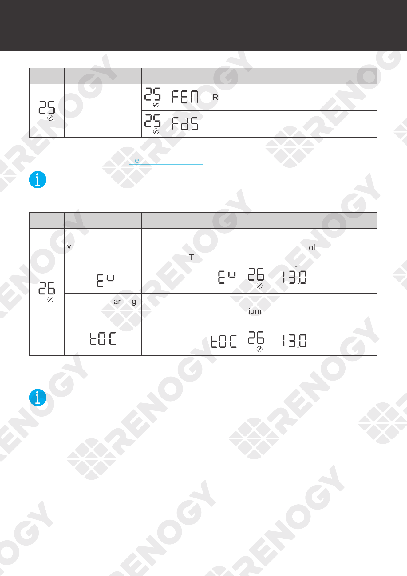
87
Program Codes
Icon Description Details
Record Fault code
Record enabled
Record disabled (default)
█
26 Boost Charging
For more instructions, read Setting Battery Type in the user manual.
NOT
E
This setting will not be modifiable if you choose a preset battery voltage. When the voltage
reaches the preset voltage, the charging will stop.
Icon Description Details
Bulk charging
voltage (C.V
voltage)
Set the bulk charging voltage after selecting the user mode in
Program 94. For non-lithium battery, set the voltage from 13.0V
to 15.0V. BATT
V
BATT
Maximum charging
voltage
Set the maximum charging voltage after selecting the user
mode in Program 94. For lithium battery, set the voltage from
13.0V to 15.5V.
V
BATT
█
27 Float Charging
For more instructions, read Setting Battery Type in the user manual.
NOT
E
z
This setting will not be modifiable if you choose a preset battery voltage.
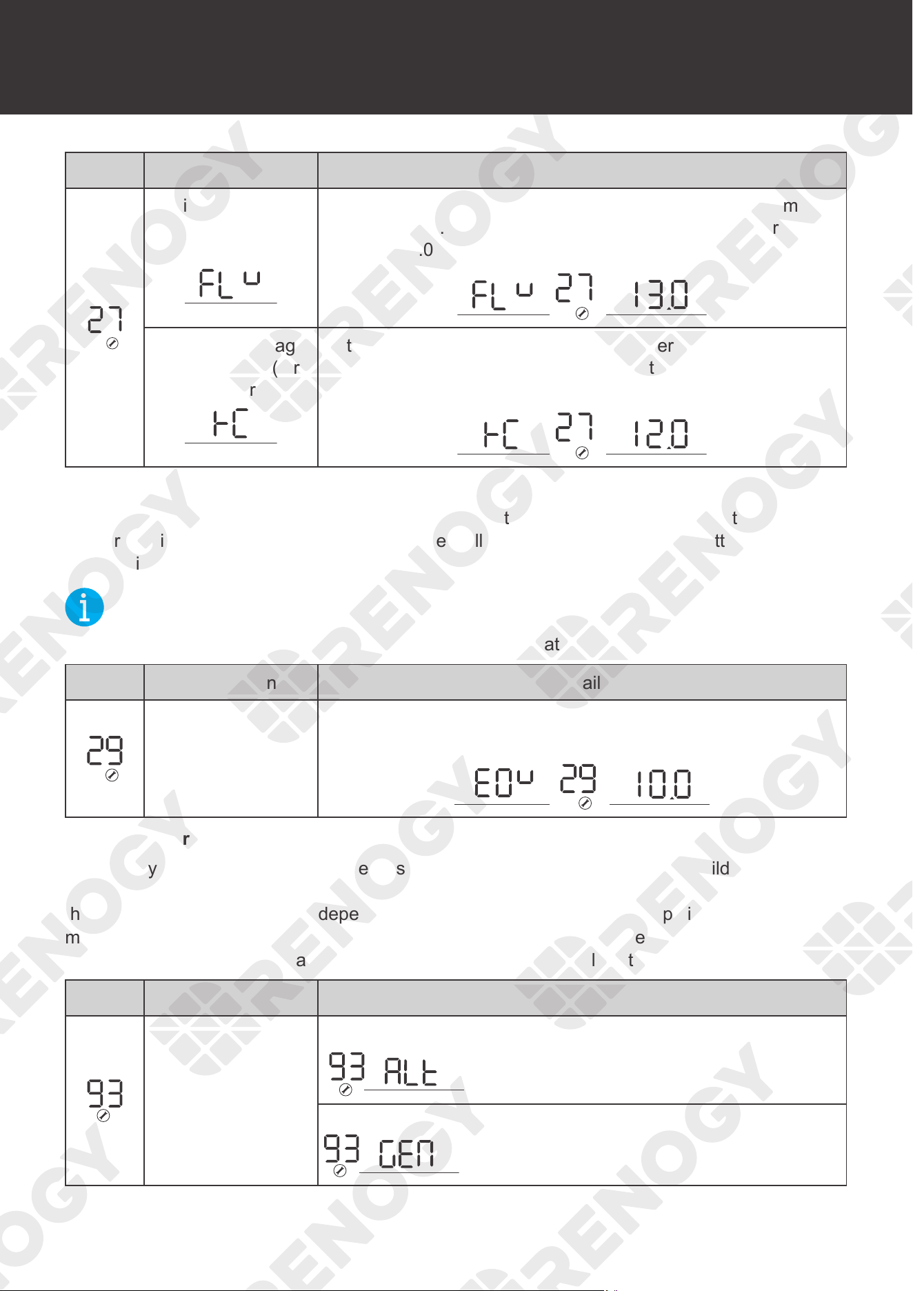
88
Program Codes
Icon Description Details
Setting Battery
Type
Set the floating charging voltage after selecting the user mode
in Program 94. For non-lithium battery, set the voltage from
13.0V to 15.0V. BATT
V
BATT
Battery low voltage
open charging (for
lithium battery)
Set battery low voltage open charging after selecting the user
mode in Program 94. For non-lithium battery, set the voltage
from 12.0V to 14.0V.
V
BATT
█
29 Low DC Cut-off Voltage
This program determines the cut-off voltage range for the battery input of the inverter charger.
Upon reaching this voltage, the inverter charger will cut off operation until the battery can go
above this voltage level.
NOT
E
z
This setting must be at least 0.5V lower than the Low Battery Voltage Alarm in Program 98.
Icon Description Details
Low DC cut-off
voltage
The default setting is 10.0V. Setting range is from 10.0V
to 12.0V with increments of 0.1V.
V
BATT
█
93 Input Frequency Range
The factory default frequency for inverters is 60 Hz. Normally, manufacturers build electrical
devices for a certain amount of Current, Voltage and Hertz (Cycles) which is mentioned on
the name plate. The Current is dependent of the Voltage and the Hertz supplied to an electric
motor or appliance. This program allows you to set the frequency range of the AC input source.
Special cases might require a wider frequency range than normal utility and generator outputs.
Icon Description Details
Frequency Range
Special 40 Hz-70 Hz
General 50 Hz 45 Hz-55 Hz / 60 Hz 55 Hz-65 Hz
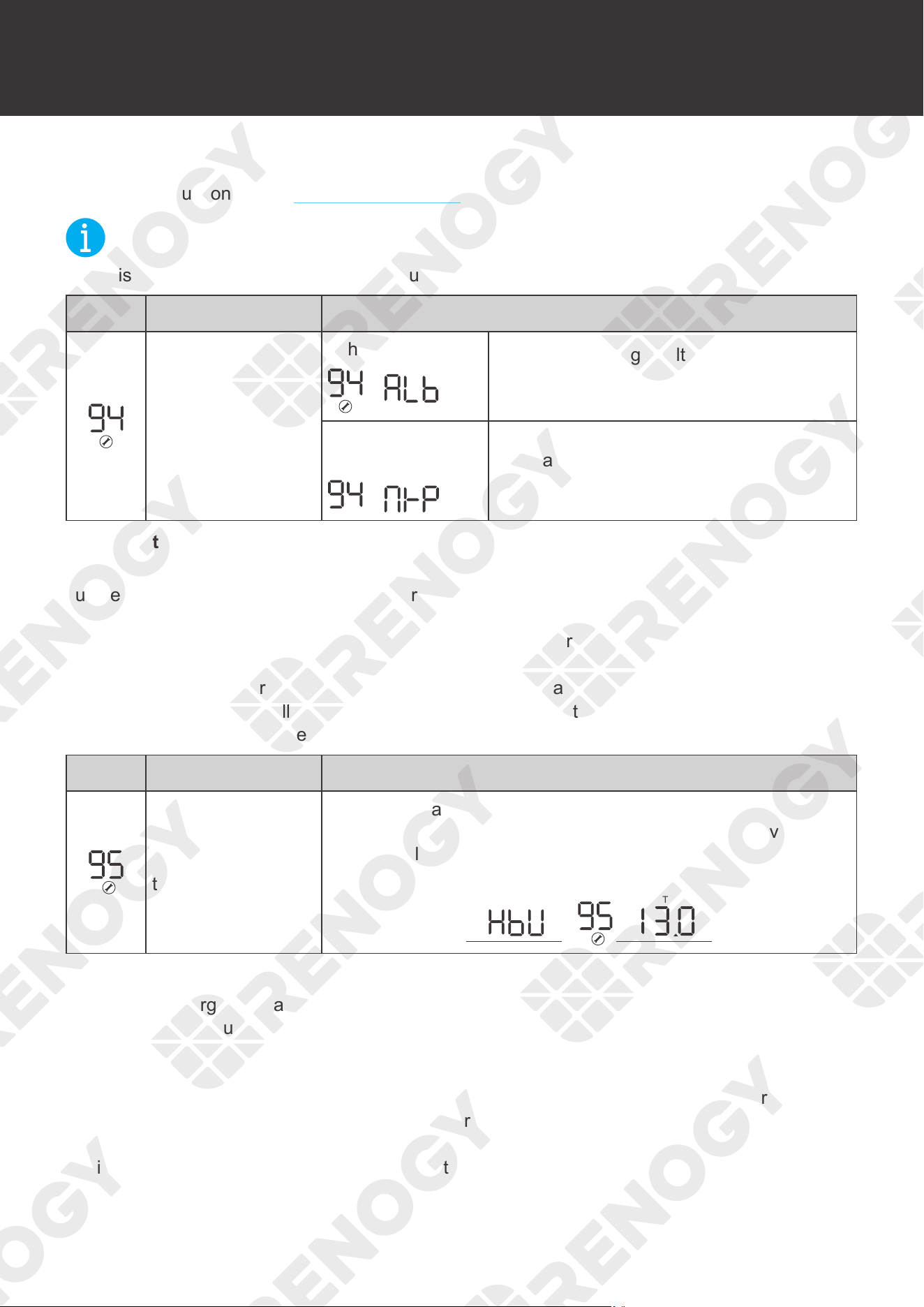
89
Program Codes
█
94 Selection of Battery Type Custom
For more instructions, read Setting Battery Type in the user manual.
NOT
E
z
This setting will not be modifiable if you choose a preset battery voltage.
Icon Description Details
Selection of battery
type
Lithium battery
The battery charge voltage and battery low
open charging can be set up in Program
26, 27
Non-lithium
battery
The battery charge voltage can be set up
in Program 26, 27
█
95 Battery High Voltage for Dry Contacts
The inverter charger have functions to automatically start and stop a generator for
supplementing charge. The auto generator feature starts the generator with the use of
Normally Closed (NC) contacts of the relay that
“opens” when the battery voltage drops to the
programmed value of Program 96. The Normally Open (NO) relay “closes”,
and the generator
starts to charge the battery bank. When the battery is recharged and its voltage rises to the
programmed value of Program 95, the NC (close) contacts and NO (open) contacts of relay
reset and the generator will stop / shut down the generator automatically.
The inverter charger
will then transfer back to Inverting Mode.
Icon Description Details
Battery high voltage
trip
The dry contacts will switch from NO to NC when the battery
voltage reaches the preset value in Program 95. This value
cannot be lower than fast charge voltage. Set the voltage from
13.0V to 15.5V.
V
BATT
█
96 Low Voltage Trip for Dry Contacts
The inverter charger can automatically start and stop a generator for supplementing charge. The
auto generator feature starts the generator with the use of Normally Closed (NC) contacts of the
relay that
“opens” when the battery voltage drops to the programmed value of Program 96, Low
Battery Voltage Setpoint. The Normally Open (NO) relay “closes”,
and the auto generator start
function enables the generator to charge the battery bank. When the battery is recharged and
its voltage rises to the programmed value of Program 95, the NC (closes) contacts and NO (open)
contacts of relay reset. Dry contacts trigger when the low voltage setpoint is reached and trigger
again when upper voltage limit is reached to stop. The inverter charger will then transfer back to
Inverting Mode.
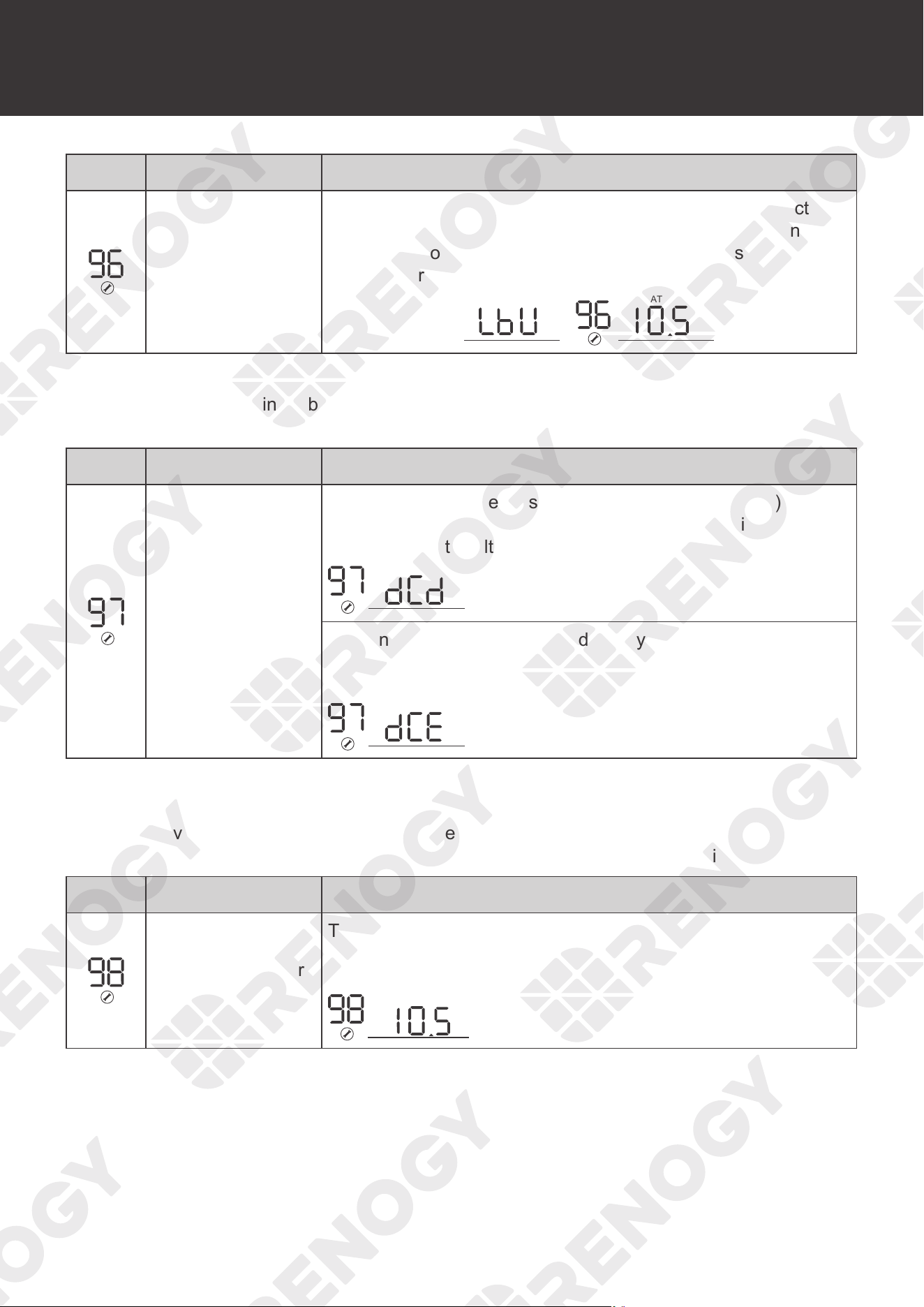
90
Program Codes
Icon Description Details
Battery low voltage
trip
When battery voltage reaches the setpoint, the dry contact
switches from NC to NO. This value cannot be lower than the
cut-off point of the low battery. The setting range is from 10.5V
to 12.5V for 12V. Increment of each press is 0.1V for 12V.
V
BATT
█
97 Dry Contacts Control
To modify the setting point of battery in Program 95 and Program 96, enable dry contact control.
This allows control over the auto generator function.
Icon Description Details
Dry contacts control
If the inverter charger is set in dcd (dry contact disable) mode,
dry contact function is disabled, When this setting is enabled,
the dry contacts voltages are set.
If the inverter charger is set in dce (dry contact enable) mode,
dry contact function is enabled and 95, 96 can be set up in
program.
█
98 Low Battery Voltage Alarm
Users can select to have the inverter charger sound an alarm at a programmable battery
voltage. The value set in Program 98 should be higher than Program 29, Low DC Cut-off
Voltage, as it will warn users that the battery is discharging before ultimately being disconnected.
Icon Description Details
Low voltage battery
alarm
The default is 10.5V. The setting range is 10.5V to 12.5V with
an increment of 0.1V. This setting will be at least 0.5V greater
than setting Program 29.
V
BATT
█
99 AC output Voltage
Allows users to customize AC output voltages for devices that might need to meet a very
specific AC input criteria.
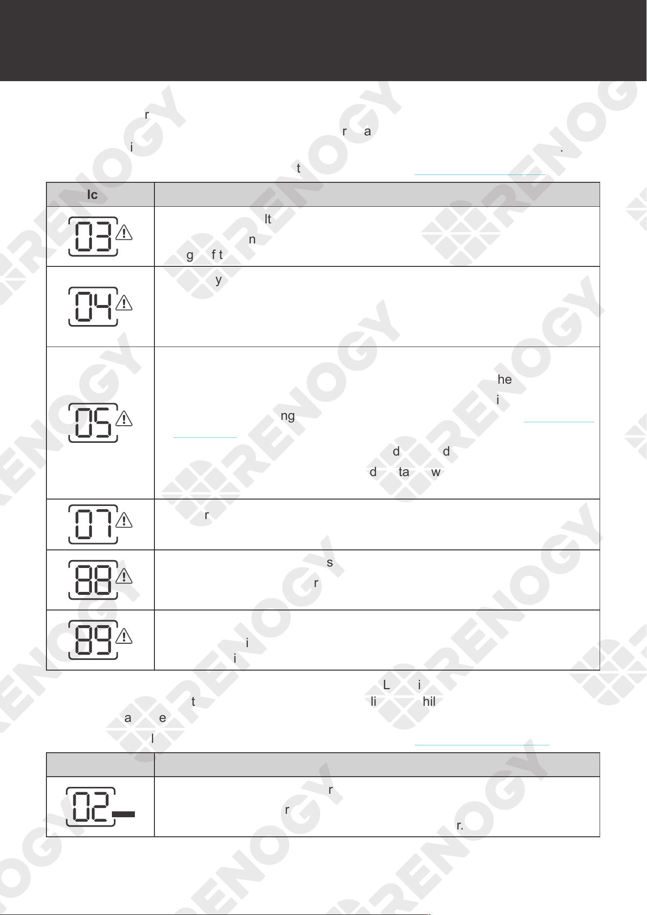
91
Warning/Fault Codes
Warning/Fault Codes
When the inverter charger needs troubleshooting, the FAULT indicator of the inverter charger
and the ERR indicator of the wired remote control are flashing red, while the buzzer beeps long
and the LCD displays the FAULT code. Troubleshoot typo according to the following table.
For more technical support, contact our custom service through renogy.com/contact-us.
Icon Warning Event
03: Battery overvoltage alarm
Shut down the inverter charger. Disconnect all cables. Check the battery
voltage. If the battery is damaged, replace it.
04: Battery low voltage alarm
1. Charge the battery immediately.
2. Check the battery voltage to conform whether the battery is damaged. If
the battery is damaged, replace it.
05: Over-temperature alarm
1. Check whether fan thermal control is blocked and affect heat dissipation.
2. Check whether the fans are running. If they are not running, the fans
need troubleshooting. Contact our customer service through renogy.com/
contact-us/.
3. Decrease the ambient temperature and the load power.
4. Shut down the inverter charger and restart it when its temperature
decreases.
07: Overload alarm
Reduce the quantity and power of the load.
88: The inverter transformer is phased in reverse
Shut down the inverter charger. Disconnect the AC input, and check
whether the AC input wiring is correct.
89: The frequency of main power is out of range
Shut down the inverter charger. Disconnect the AC input power. Check that
the AC input is within the rated frequency range of 40 Hz to 70 Hz.
When the inverter charger needs troubleshooting, the FAULT indicator of the inverter charger
and the ERR indicator of the wired remote control are solid red, while the buzzer beeps long and
the LCD displays the FAULT code. Troubleshoot faluts according to the following table.
For more technical support, contact our custom service through renogy.com/contact-us/.
Icon Warning Event
ERROR
02: Short circuit of the inverter charger
Shut down the inverter charger. Check whether the load is short-circuited. If
it is, replace the load and restart the inverter charger.
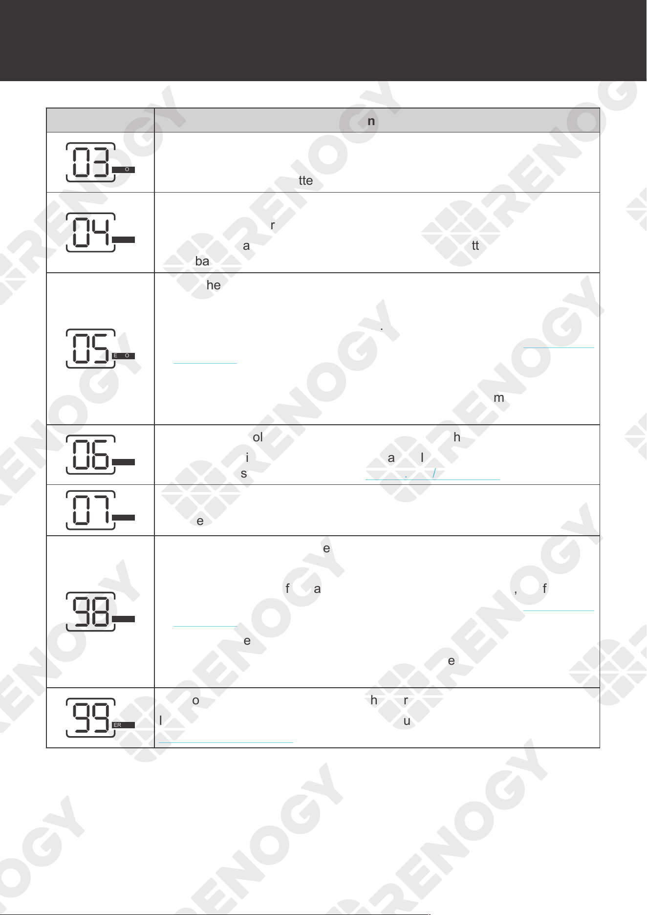
92
Warning/Fault Codes
Icon Warning Event
ERROR
03: Battery high voltage
Shut down the inverter. Disconnect all cables connected to it. Check the
battery voltage. If the battery is damaged, replace it.
ERROR
04: Battery low voltage
1. Charge the battery immediately.
2. Check the battery voltage to confirm whether the battery is damaged. If
the battery is damaged, replace it.
ERROR
05: The heat sink of inverter charger is overheated
1. Check whether fan thermal control is blocked and affect heat dissipation.
2. Check whether the fans are running. If they are not running, the fans
need troubleshooting. Contact our customer service through renogy.com/
contact-us/.
3. Decrease the ambient temperature and the load power.
4. Shut down the inverter charger and restart it when its temperature
decreases.
ERROR
06: The output voltage of inverter charger is too high or too low
Shut down the inverter charger and restart it. If the fault still persists,
contact our custom service through renogy.com/contact-us/.
ERROR
07: Inverter charger overloaded
Reduce the quantity and power of the load.
ERROR
98: The transformer of inverter charger is overheated
1. Check whether fan thermal control is blocked and affect heat dissipation.
2. Check whether the fans are running. If they are not running, the fans
need troubleshooting. Contact our customer service through renogy.com/
contact-us/.
3. Decrease the ambient temperature and the load power.
4. Shut down the inverter charger and restart it when its temperature
decreases.
ERROR
99: Slow start failure of the inverter charger
If the inverter fails to start slowly, contact our custom service through
renogy.com/contact-us/.

93
Technical Specifications
Technical Specifications
Inverter Specifications
Rated Output Power 3000W
Surge Power (1 second) 9000W
Surge Power (3 seconds) 4500W
Surge Power (10 seconds) 3600W
Nominal Output Voltage RMS 120V AC (100V to 120V AC, 5V intervals)
Outuput Frequency 50 Hz (
±
0.3 Hz) or 60 Hz (
±
0.3 Hz)
Output Wave Form Pure Sine Wave
Output Overload
105% < Load < 120%
(±
10%)
Fault (Turn off output after 10 seconds)
120% < Load < 150% (
±
10%)
Fault (Turn off output after 3 seconds)
150% < Load (
±
10%)
Fault (Turn off output after 1 seconds)
Nominal Input Voltage 12V DC
Input Voltage Range 11V to 16V DC (
±
0.3V)
Low DC Warning Voltage 11V DC (
±
0.3V)
Low DC Cut-off Voltage 10.5V DC (
±
0.3V)
Short Circuit Protection Software Protection
Nominal Efficiency > 90% Peak
No Load Power Consumption Normal: < 30W
Charger Specifications
Nominal Input Voltage 120V AC
Input Voltage Range 90V to 138V AC
Input Frequency Range 40 Hz to 70 Hz
Input Wave Form Sine Wave (Utility or Generator)
Power Factor 0.9 to 1
Optimal Efficiency > 85%
Output Current
5A to 75A
Configurable, 5A intervals
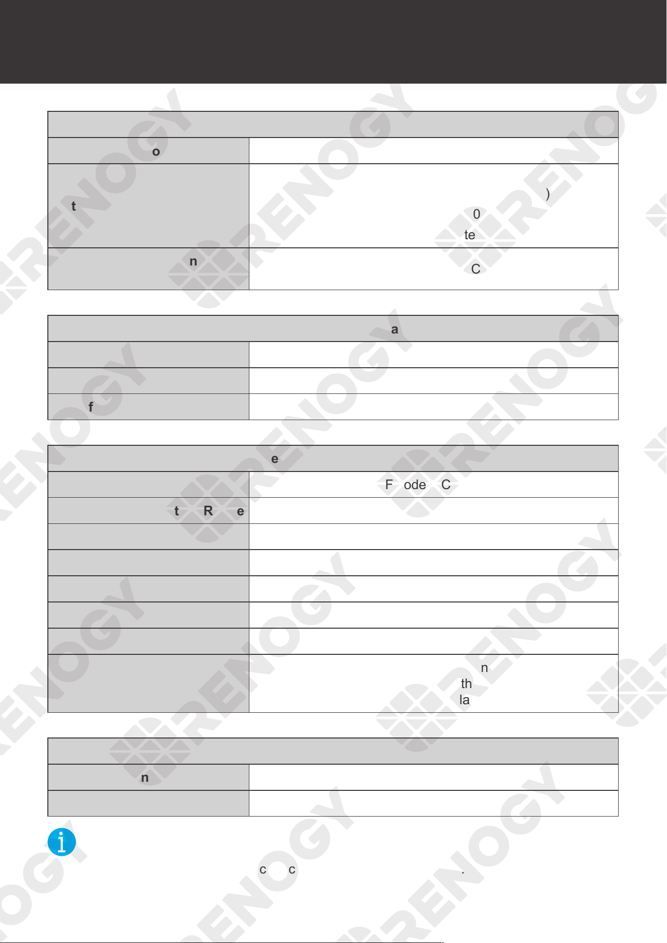
94
Technical Specifications
Charger Specifications
Short Circuit Protection Circuit Breaker
Output Overload
120% < Load < 150% (
±
10%)
Fault (Turn off output after 60 seconds)
150% < Load (
±
10%)
Fault (Turn off output after 1 second)
Overcharge Protection
Shutdown
16V for 12V DC
Transfer Switch Specifications
Transfer Time 10 ms
Line Mode Efficiency > 95%
Transfer Relay Rating 40A Maximum Bypass
General Specifications
Battery Types Gel, AGM, SLA, Flooded, Calcium, Li, User Mode
Operating Temperature Range -20
°
F to 104
°
F or -20
°C
to 40
°C
Storage Temperature -22
°
F to 158
°
F or -30
°C
to 70
°C
Humidity 0% to 95%
Noise < 50 dB
Dimensions 20.1 x 11.2 x 7.6 in / 510 x 285 x 193 mm
Weight 63.5 lbs / 28.8 Kg
Certifications
ETL listed to CSA Standard
C22.2 No. 107.1 and UL458 with marine supplement
FCC part 15 Class A
Wired Remote Control
List Dimensions 2.8 x 4.3 x 1.3 in / 70 x 110 x 31.8 mm
Wire Length Approx 16.4 ft
NOT
E
z
Product specifications are subject to change without further notice.
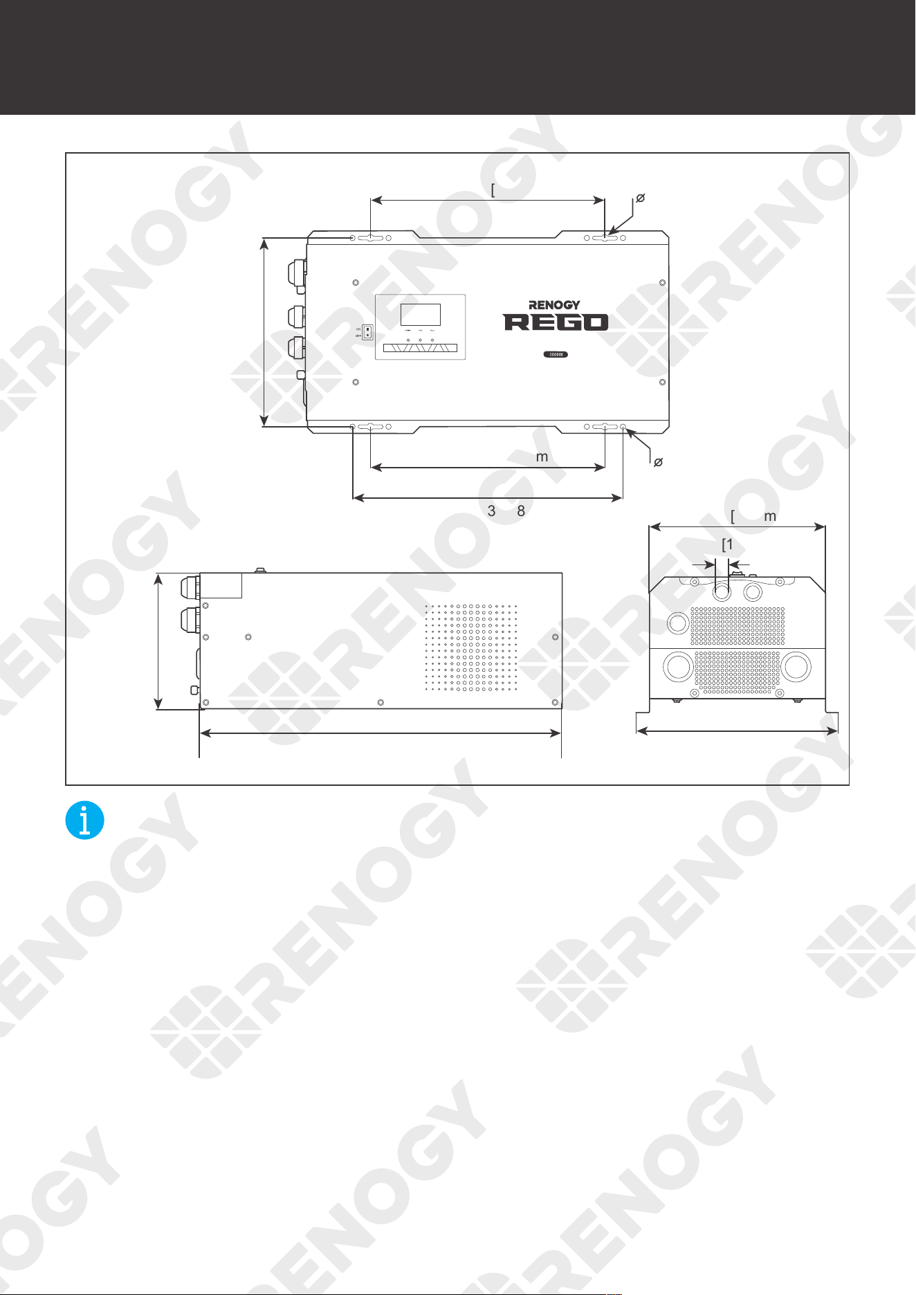
95
Dimensions
Dimensions
12.99 in [330 mm]
0.35 in [9 mm]
12.99 in [330 mm]
20.07 in [510 mm]
11.22 in [285 mm]
9.76 in [248 mm]
0.51 in [13 mm]
14.99 in [380.8 mm]
8.89 in
[266 mm]
7.58 in
[192.7 mm]
0.28 in [7 mm]
Pure Sine Wave Inverter Charger
NOT
E
z
Dimension tolerance: ±0.2 in (0.5 mm)
96
Maintenance
Maintenance
Inspection
For optimum performance, it is recommended to perform these tasks regularly.
z
Ensure the inverter charger is installed in a clean, dry and ventilated area.
z
Ensure there is no damage or wear on the cables.
z
Ensure the firmness of the connectors and check if there are any loose, damaged or burnt
connections.
z
Make sure the AC/INV indicator, CHG indicator and FAULT indicator are in proper condition.
z
Ensure there is no corrosion, insulation damage, or discoloration marks of overheating or
burning.
z
If the inverter charger is dirty, use a damp cloth to clean the outside of the device to prevent
dust and dirt from accumulating. Before the inverter charger is powered on, make sure it is
completely dry after cleaning.
z
Make sure the ventilation holes are not blocked.
WARNIN
G
z
Risk of electric shock! Make sure that all power supplies are turned off before touching
terminals on the inverter charger.
Cleaning
Follow the steps below to clean the inverter charger regularly.
z
Disconnect all cables connected to the inverter charger.
z
Wear proper protective equipment and use insulated tools during operation. Be careful when
touching bare terminals of capacitors as they may retain high lethal voltages even after
power is removed.
z
Wipe the housing of the inverter charger and connector contacts with a dry cloth or non-
metallic brush. If it is still dirty, you can use household cleaners.
z
Make sure the ventilation holes are not blocked.
z
Dry the inverter charger with a clean cloth and keep the area around the inverter charger
clean and dry.
z
Make sure the inverter charger is completely dry before reconnecting it to the battery and AC
input.
Storage
Follow the tips below to ensure that the inverter charger is stored well.
z
Disconnect all cables connected to the inverter charger.
z
By applying dielectric grease to each connector contact, the dielectric grease repels
moisture and protects the connector contacts from corrosion.
z
Store the inverter charger in a well-ventilated, dry, and clean environment with the
temperature between 22
°
F to 158
°
F or 30
°C
to 70
°C
.
Inspection Cleaning Storage
97
Emergency Responses
Emergency Responses
In the event of any threat to health or safety, always begin with the steps below before
addressing other suggestions.
z
Immediately contact the fire department or other relevant emergency response team.
z
Notify all people who might be affected and ensure that they can evacuate the area.
WARNIN
G
z
Only perform the suggested actions below if it is safe to do so.
Fire
1. Disconnect all cables connected to the inverter charger.
2. Put out the fire with a fire extinguisher. Acceptable fire extinguishers include water, CO
2
, and
ABC.
WARNIN
G
z
Do not use type D (flammable metal) fire extinguishers.
Flooding
1. If the inverter charger is submerged in water, stay away from the water.
2. Disconnect all cables connected to the inverter charger.
Smell
1. Disconnect all cables connected to the inverter charger.
2. Ensure that nothing is in contact with the inverter charger.
3. Ventilate the room.
Noise
1. Disconnect all cables connected to the inverter charger.
2. Make sure no foreign objects are stuck in the fan of the inverter charger or the ring terminal.
NOT
E
z
The normal noise value of the inverter charger is less than 50dB during operation.
Fire Flooding Smell Noise
98
Technical Support
For additional support, contact the Renogy technical support team through renogy.com/contact-
us. Have the following information available when contacting Renogy.
z
Owner name
z
Contact information
z
Order number
z
Purchase channel
z
Serial number
z
Brief description of the issue
Renogy offers premium services worldwide:
North America US
www.renogy.com
CN
www.renogy.cn
Asia/Pacific
UK
uk.renogy.com
CA
ca.renogy.com
AU
au.renogy.com
JP
renogy.jp
Europe
FR
fr.renogy.com
DE
de.renogy.com
ES
es.renogy.com
KR
kr.renogy.com
Technical Support
99
FCC Statement
This device complies with Part 15 of the FCC Rules. FCC ID: 2ANPBRSMLP4-G2. Operation is
subject to the following two conditions:
(1) This device may not cause harmful interference.
(2) This device must accept any interference received, including interference that may cause
undesired operation.
This equipment has been tested and found to comply with the limits for a Class A
digital
device, pursuant to Part 15 of the FCC Rules. These limits are designed to provide reasonable
protection against harmful interference in a residential installation. This equipment generates,
uses and can radiate radio frequency energy and, if not installed and used in accordance with
the instructions, may cause harmful interference to radio communications. However, there is no
guarantee that interference will not occur in a particular installation. If this equipment does cause
harmful interference to radio or television reception, which can be determined by turning the
equipment off and on, the user is encouraged to try to correct the interference by one or more of
the following measures:
(1) Orient or relocate the receiving antenna.
(2) Increase the separation between the equipment and receiver.
(3) Connect the equipment into an outlet on a circuit different from that to which the receiver is
connected.
(4) Consult the dealer or an experienced radio/TV technician for help.
FCC Radiation Exposure Statement
This equipment complies with FCC radiation exposure limits set forth for an uncontrolled
environment. This equipment should be installed and operated with minimum distance 20 cm
between the radiator & your body.