VERSION A0
HF Inverter Charger
REGO
12V 30 0 0 W
RIV1230 RCH- SPS
USER MANUAL
Before Getting Started
The user manual provides important operation and maintenance instructions for REGO 12V 3000W HF
Inverter Charger (hereinafter referred to as inverter charger).
Read the user manual carefully before operation and save it for future reference. Failure to observe the
instructions or precautions in the user manual can result in electrical shock, serious injury, or death, or
can damage the inverter charger, potentially rendering it inoperable.
z
Renogy ensures the accuracy, sufficiency, and the applicability of information in the user manual
at the time of printing due to continual product improvements that may occur.
z
Renogy assumes no responsibility or liability for personal and property losses, whether directly and
indirectly, caused by the user’s failure to install and use the product in compliance with the user
manual.
z
Renogy is not responsible or liable for failures, damages, or injuries resulting from repair attempted
by unqualified personnel, improper installation, and unsuitable operation.
z
The illustrations in the user manual are for demonstration purposes only. Details may appear
slightly different depending on product revision and market region.
z
Renogy reserves the right to change the information in the user manual without notice. For the
latest user manual, visit
renogy.com.
Disclaimer
REGO 12V 3000W HF Inverter Charger User Manual © 2023 Renogy. All rights reserved.
RENOGY
and
are registered trademarks of Renogy.
z
All information in the user manual is subject to copyright and other intellectual property rights of
Renogy and its licensors. The user manual may not be modified, reproduced, or copied, in whole or
in part, without the prior written permissions of Renogy and its licensors.
z
The registered trademarks in the user manual are the property of Renogy. The unauthorized use of
the trademarks is strictly prohibited.
Online Manual
Quick Guide User Manual
DC Home App
DC Home App
Download on the

1. General Information ........................................................................................................................... 1
1.1. Symbols Used .............................................................................................................................................. 1
1.2. Qualified Personnel.....................................................................................................................................1
1.3. Introduction .................................................................................................................................................1
1.4. Key Features ................................................................................................................................................ 1
1.5. SKU ................................................................................................................................................................ 2
2. Get to Know REGO 12V 3000W HF Inverter Charger .......................................................................3
2.1. What’s In the Box? ...................................................................................................................................... 3
2.2. Recommended Tools ................................................................................................................................. 3
2.3. Product Overview ....................................................................................................................................... 4
2.4. System Setup ............................................................................................................................................. 5
3. Preparation .........................................................................................................................................6
3.1. Plan a Mounting Site ................................................................................................................................. 6
3.2. Check the Inverter Charger ....................................................................................................................... 7
3.3. Check the Battery ...................................................................................................................................... 8
3.4. Check the AC Loads (Appliances) ..........................................................................................................10
3.5. Check the AC Generator or the Grid (Optional) ................................................................................... 11
3.6. How to Properly Install Cable Clamps? ................................................................................................. 12
4. Installation ........................................................................................................................................ 13
4.1. Wear Insulating Gloves ............................................................................................................................. 13
4.2. Mount the Inverter Charger ....................................................................................................................13
4.3. Remove the Cover .....................................................................................................................................14
4.4. Ground the Inverter Charger ..................................................................................................................14
4.5. Install a Wired Remote Control ...............................................................................................................15
4.6. Install a Battery Voltage Sensor ............................................................................................................. 16
4.7. Install a Battery Temperature Sensor ...................................................................................................18
4.8. Connect the Inverter Charger to a Battery .......................................................................................... 19
4.9. Connect the Inverter Charger to AC Loads (Appliances) .................................................................. 21
4.10. Connect the Inverter Charger to the Grid ........................................................................................... 24
4.11. CAN Communication Wiring (Optional) ................................................................................................ 29
4.12. Inspection .................................................................................................................................................. 32
4.13. Install the Cover .......................................................................................................................................32
5. Configuration ....................................................................................................................................33
5.1. N-G Bonding Relay ................................................................................................................................... 33
5.2. Configuration Panel .................................................................................................................................34
5.3. Set a Battery Type ....................................................................................................................................34
5.4. USER Mode ................................................................................................................................................ 35
5.5. Enable/Disable the Buzzer..................................................................................................................... 37
5.6. Set an AC Output Frequency ................................................................................................................. 37
5.7. Set an AC Output Priority ....................................................................................................................... 37
Table of Contents

6. Power On/Off and LED Indicators ...................................................................................................38
6.1. Power On/Off ............................................................................................................................................38
6.2. LED Indicators .......................................................................................................................................... 39
7. Monitor the Inverter Charger ......................................................................................................... 40
7.1. Short-Range Monitoring via DC Home App ........................................................................................40
7.2. Wireless Long-Range Monitoring ..........................................................................................................41
7.3. Wired Long-Range Monitoring (Backbone Network) ........................................................................ 42
7.4. Wired Long-Range Monitoring (Daisy Chain Network) .....................................................................43
8. Working Logic ................................................................................................................................... 44
8.1. Power Supply Logic .................................................................................................................................44
8.2. Charging Logic..........................................................................................................................................45
8.3. Battery Charging Stages ........................................................................................................................ 46
8.4. Heat Dissipation Logic ............................................................................................................................ 47
8.5. Activation Logic for Lithium Battery .................................................................................................... 47
8.6. Heating Module Activation Logic for Lithium Battery ...................................................................... 47
9. Troubleshooting............................................................................................................................... 48
10. Dimensions & Specifications ...........................................................................................................49
10.1. Dimensions ................................................................................................................................................49
10.2. Technical Specifications .........................................................................................................................49
11. Maintenance ...................................................................................................................................... 51
11.1. Inspection .................................................................................................................................................. 51
11.2. Cleaning ......................................................................................................................................................51
11.3. Storage ........................................................................................................................................................ 51
12. Emergency Responses .....................................................................................................................52
12.1. Fire ..............................................................................................................................................................52
12.2. Flooding ..................................................................................................................................................... 52
12.3. Smell ........................................................................................................................................................... 52
12.4. Noise ........................................................................................................................................................... 52
Renogy Support
........................................................................................................................................53

— 1 —
1. General Information
1.1. Symbols Used
The following symbols are used throughout the user manual to highlight important information.
WARNING: Indicates a potentially hazardous condition that could result in personal injury or
death.
CAUTION: Indicates a critical procedure for safe and proper installation and operation.
NOTE: Indicates an important step or tip for optimal performance.
1.2. Qualified Personnel
The installation and service of the inverter charger must be carried out by qualified personnel. Qualified
personnel refer to trained and licensed electricians or installers with all the following skills and expertise:
z
Knowledge of the functional principles and operation of on-grid and off-grid energy storage system.
z
Knowledge of the risks and dangers associated with the installation and service of electrical devices
and acceptable mitigation methods.
z
Knowledge of the installation and service of electrical devices.
z
Knowledge of and adherence to the user manual and all safety precautions and best practices.
z
Knowledge of local installation regulations.
z
Electrical license for the installation and service of energy storage system required by the county or
state.
1.3. Introduction
REGO 12V 3000W HF Inverter Charger is your off-grid smart living center that revolutionizes comfort
when you live in your off-grid home or RV. The inverter charger can invert DC to AC and directly supply
power to the load, and charge the battery when it is connected to the utility power.
In addition, it supports different types of batteries such as lithium, GEL, flooded, SLD, and AGM
batteries. The inverter charger can switch power supply from the grid power to batteries within 10
milliseconds, ensuring a smooth mode switch without powering off the load. The lever style connectors
make AC IN/OUT connections simply and easy. They simplify installation and shorten the installation
time.
The inverter charger can be connected to Renogy devices and smart accessories via Bluetooth or RV-
C. When the inverter charger works in association with the DC Home app or Renogy ONE, you will have
the same system monitoring wherever you go on your smartphone. With advanced pure sine wave
technology, the inverter charger can protect and extend the life of your electronic equipment and loads.
1.4. Key Features
z
Battery versatility and easy-to-configure settings
Compatible with four preset battery types and allows custom parameter settings. Provides simple
switch setup for battery type, output frequency, and input priority setting.
z
Multi-stage battery charging and customizable charging
Offers up to three-stage charging for various battery types and supports adjustable charging current
(up to 150A) to suit your daily power needs.
z
Dual voltage support and high-current output
Compatible with single-phase 120V and split-phase 120V/240V.
Integrates a 50A AC Transfer Relay for continuous 50A current to AC output when connected to both
the grid and battery.
z
Built-in Bluetooth
Connects to DC Home app for energy data monitoring, control, and configuration and supports OTA
firmware upgrades.

— 2 —
z
High conversion efficiency thanks to quality pure sine wave
Achieves peak conversion efficiency of over 90%, reducing energy loss thanks to the smooth AC
power with minimal harmonic distortion, equivalent to grid power quality.
z
Automatic generator start
Equipped with dry contacts for automatic generator start and stop function, facilitating battery
charging.
z
Multiple protections
Provides undervoltage, overvoltage, overcurrent, overload, overtemperature, and short circuit
protections for enhanced safety.
1.5. SKU
REGO 12V 3000W HF Inverter Charger RIV1230RCH-SPS
— 3 —
2. Get to Know REGO 12V 3000W HF Inverter Charger
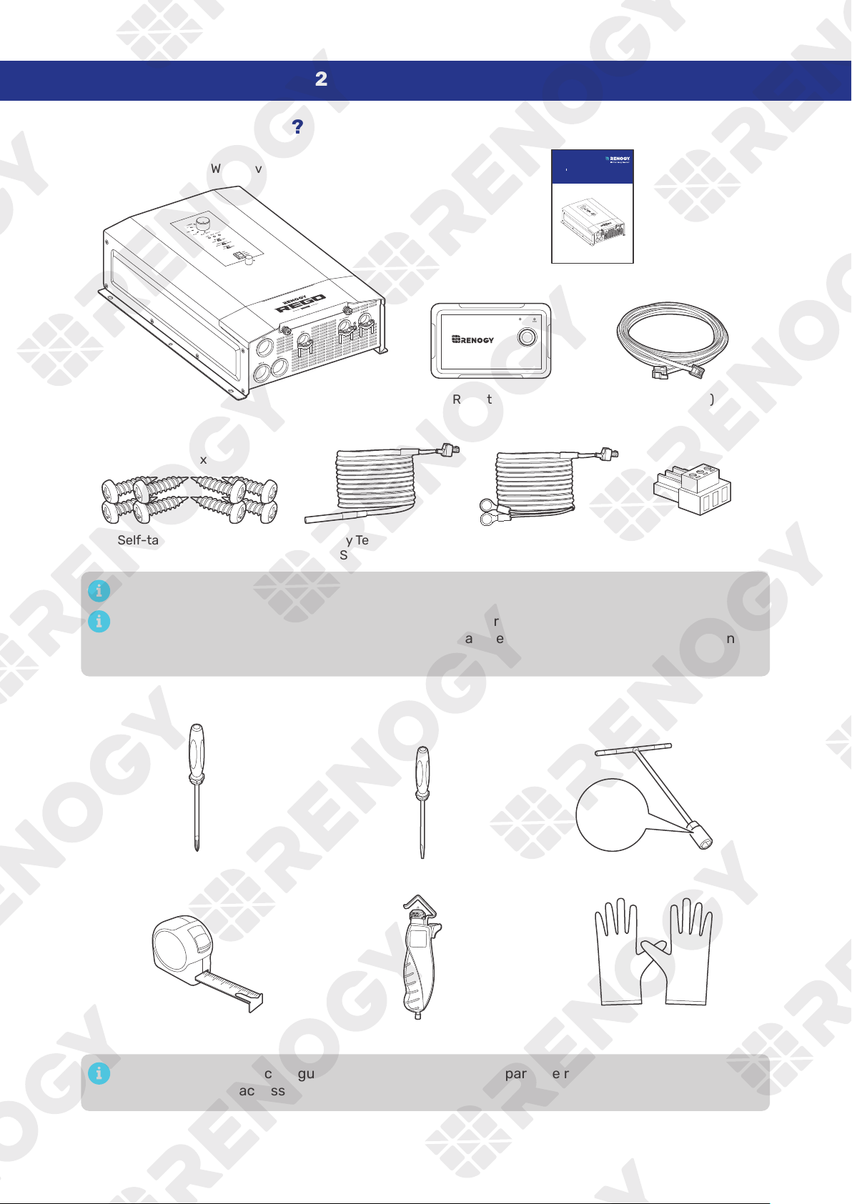
2.1. What’s In the Box?
REGO 12V 3000W HF Inverter Charger × 1
Quick Guide × 1
VERSION A0
HF Inv ert er Charg er
REGO
12V 30 00 W
RIV1230RCH- SPS
QU ICK GUID E
Self-tapping Screws x 8
(2 extra)
ST6.3 x 1.8 x 13 mm
Dry Contact Relay
Connector × 1
Wired Remote Control x 1
ON ERR
RMS-P2
RJ12 Cable (5m) x 1
Battery Voltage
Sensor × 1
Battery Temperature
Sensor x 1
Make sure that all accessories are complete and free of any signs of damage.
The accessories and product manual listed are crucial for the installation, excluding warranty
information and any additional items. Please note that the package contents may vary depending
on the specific product model.
2.2. Recommended Tools
Phillips Screwdriver (#2) Socket Wrench (17/32 in)
13 mm
Measuring Tape
3
4
5
6
Wire stripper
Slotted Screwdriver (1 mm)
Insulating Gloves
13 mm
Prior to installing and configuring the inverter charger, prepare the recommended tools,
components, and accessories.
— 4 —
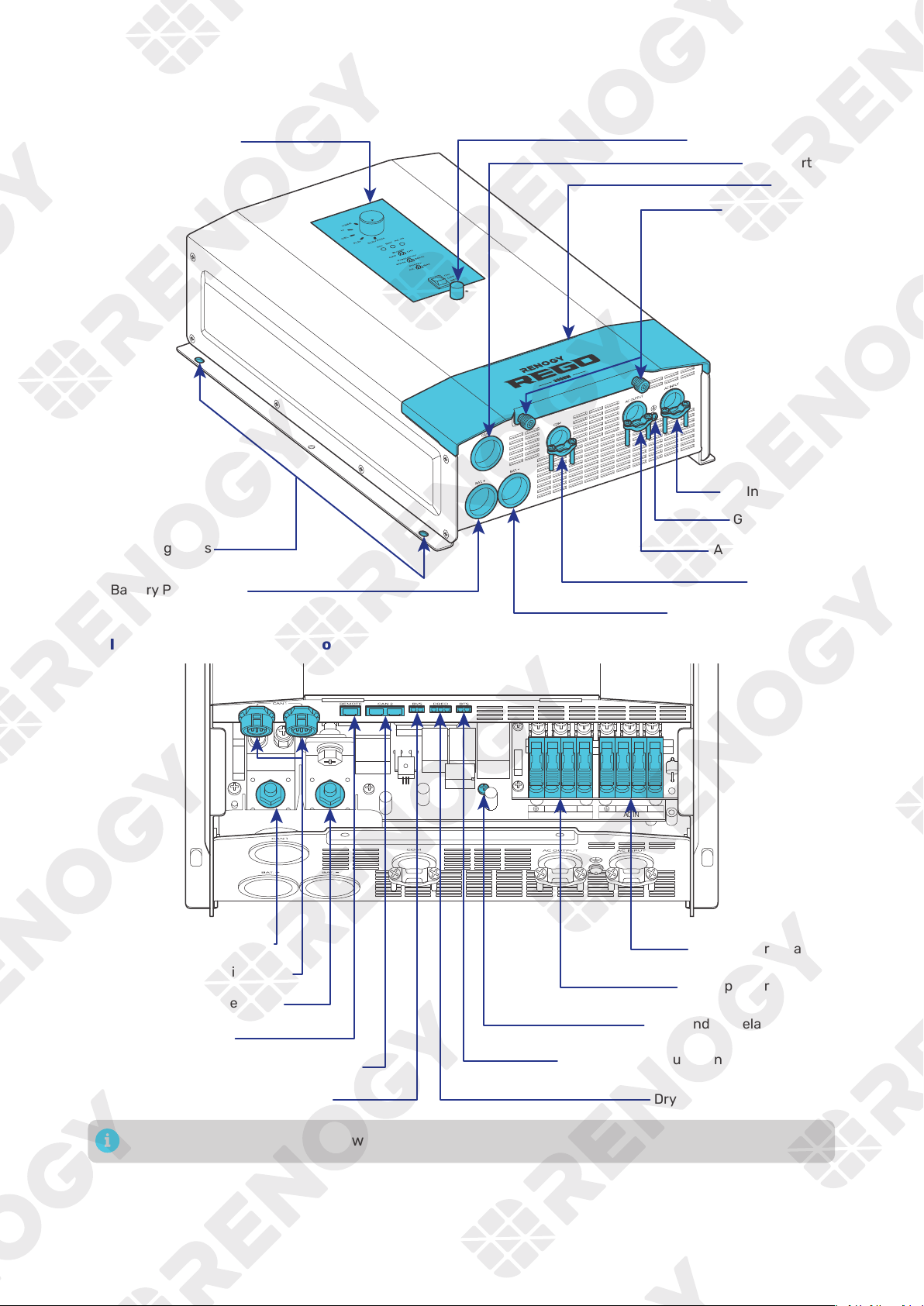
2.3. Product Overview
█
Exterior
Bluetooth Antenna
█
Interior (with the cover removed)
N L2
AC OUT
L1 N L2
AC IN
L1
Battery Positive Terminal
Battery Negative Terminal
Wired Remote Port
AC Input Terminals
AC Output Terminals
Battery Temperature Sensor (BTS) Port
Dry Contact Port (DRED)
N-G Bonding Relay Screw
CAN1 Communication Ports
CAN2 Communication Ports (reserved)
Battery Voltage Sensor (BVS) Port
The BTS port can only be used with lead-acid batteries.
— 5 —
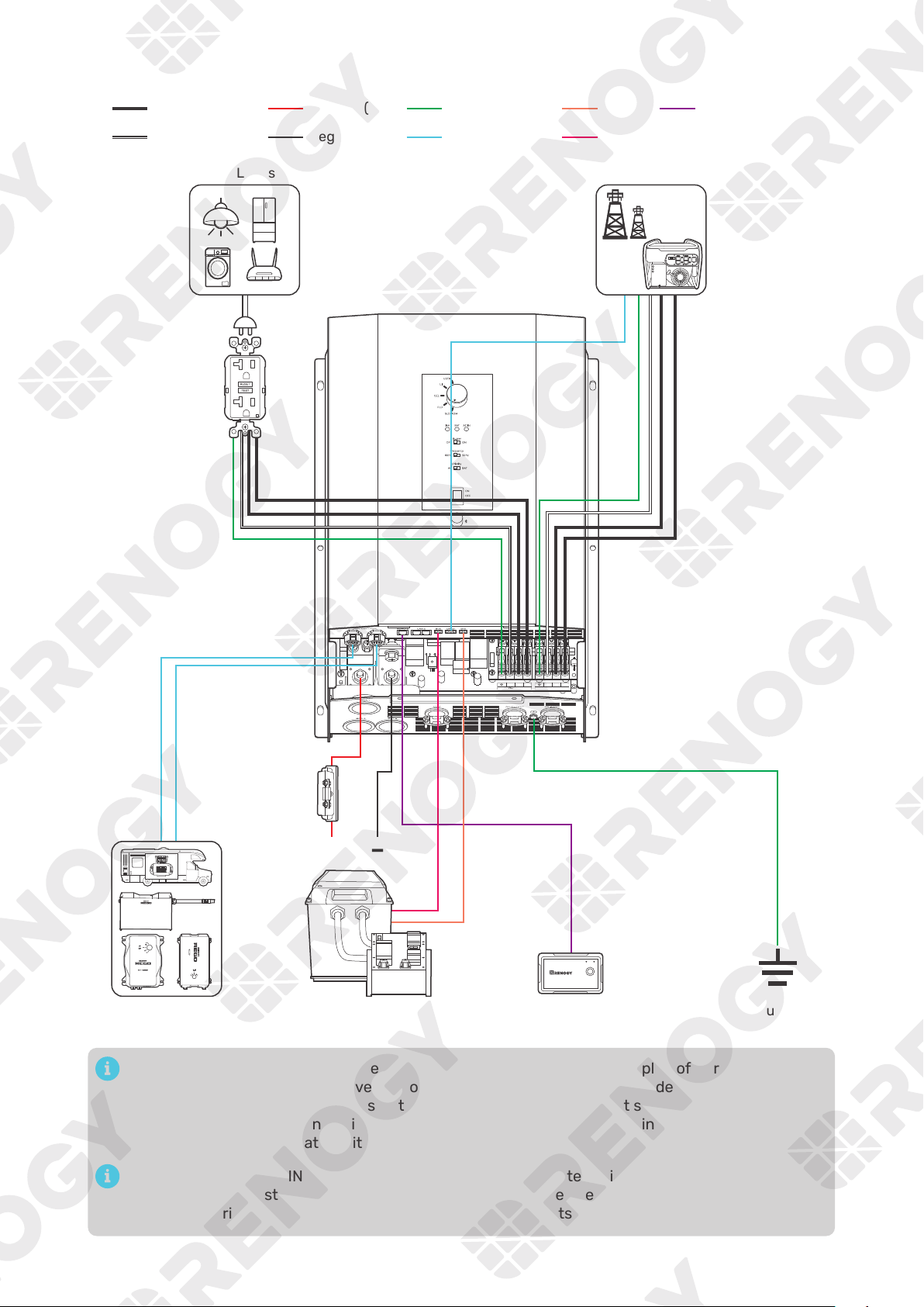
2.4. System Setup
N L2
AC OUT
L1 N L2
AC IN
L1
BAT-
BAT+
Communication
BTSGround Remote control
BVSNegative (DC)
Positive (DC)
Neutral wire (AC)
Live wire (AC)
Grounding
Battery System
(12V)
Fuse
(400A)
RV-C or REGO
Series Devices
+
-
AC Loads
Ground
Fault
Circuit
Interrupter
(GFCI)
Wired Remote
Control
ON ERR
RMS-P2
DC-DC Battery Charger
Grid Power
The wiring diagram only shows the key components in a typical DC-coupled off-grid energy
storage system for the illustrative purpose. The wiring might be different depending on the
system configuration. Additional safety devices, including disconnect switches, emergency
stops, and rapid shutdown devices, might be required. Wire the system in accordance with the
regulations at the installation site.
The connection of AC IN ports vary depending on the connected grid systems. For single-
phase 120V grid systems, only AC IN L1 and AC IN N ports are used for the input. For split-phase
120V/240V grid systems, AC IN L1, AC IN L2, and AC IN N ports are used for the input.
— 6 —
3. Preparation
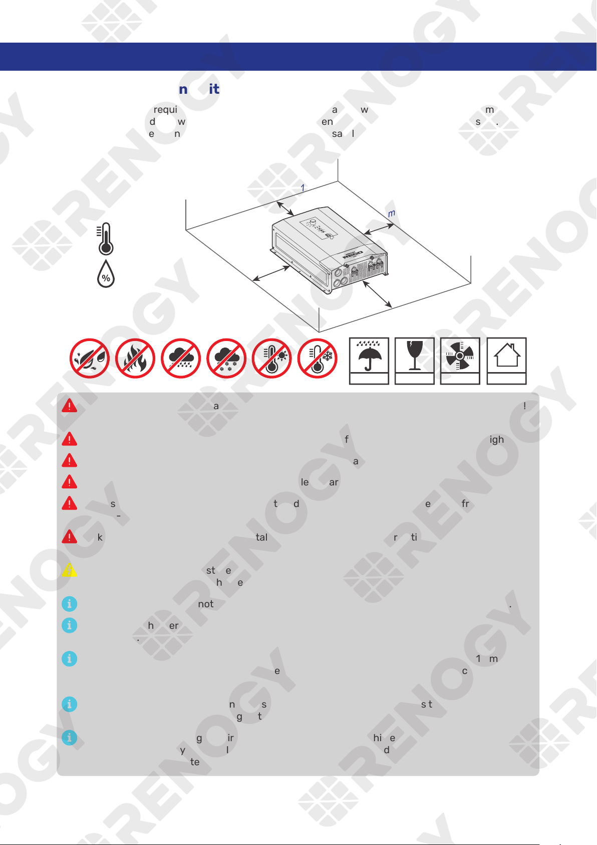
3.1. Plan a Mounting Site
The inverter charger requires adequate clearance for installation, wiring and ventilation. The minimum
clearance is provided below. Ventilation is highly recommended if it is mounted in an enclosure. Select a
proper mounting site to ensure the inverter charger can be safely connected to the battery and grid/AC
generator with the relevant cables.
KEEP DRY FRAGILE
VENTILATION
-4°F to 140°F
-20°C to 60°C
0% to 95%
INDOOR
7 in
[178 mm]
7 in
[178 mm]
10 in
[254 mm]
10 in
[254 mm]
Risk of explosion! Never install the inverter charger in a sealed enclosure with flooded batteries!
Do not install the inverter charger in a confined area where battery gases can accumulate.
The inverter charger should be installed on a vertical surface protected from direct sunlight.
Keep the inverter charger out of the reach of children and animals.
Do not expose the inverter charger to flammable or harsh chemicals or vapors.
Make sure that the inverter charger is installed in a place at ambient temperature from -4°F to
140°F (-20°C to 60°C).
Make sure that inverter charger is installed in an environment with relative humidity between 0%
and 95% and no condensation.
If the inverter charger is installed improperly on a boat, it may cause damage to components of
the boat. Have the inverter charger by a qualified electrician.
The inverter charger cannot operate at full load in ambient temperatures above 113°F (45°C).
The inverter charger should be as close to the battery as possible to avoid voltage drop due to
long cables.
It is recommended that all cables (except communication cables) should not exceed 10 meters
(32.8 feet) because excessively long cables result in a voltage drop. The communication cables
should be shorter than 6 m (19.6 feet).
The cable specifications listed in the user manual account for critical, less than 3% voltage drop
and may not account for all configurations.
Ensure the inverter charger is firmly grounded to a building, vehicle, or earth grounded. Keep the
inverter charger away from EMI receptors such as TVs, radios, and other audio/visual electronics
to prevent damage / interference to the equipment.
— 7 —
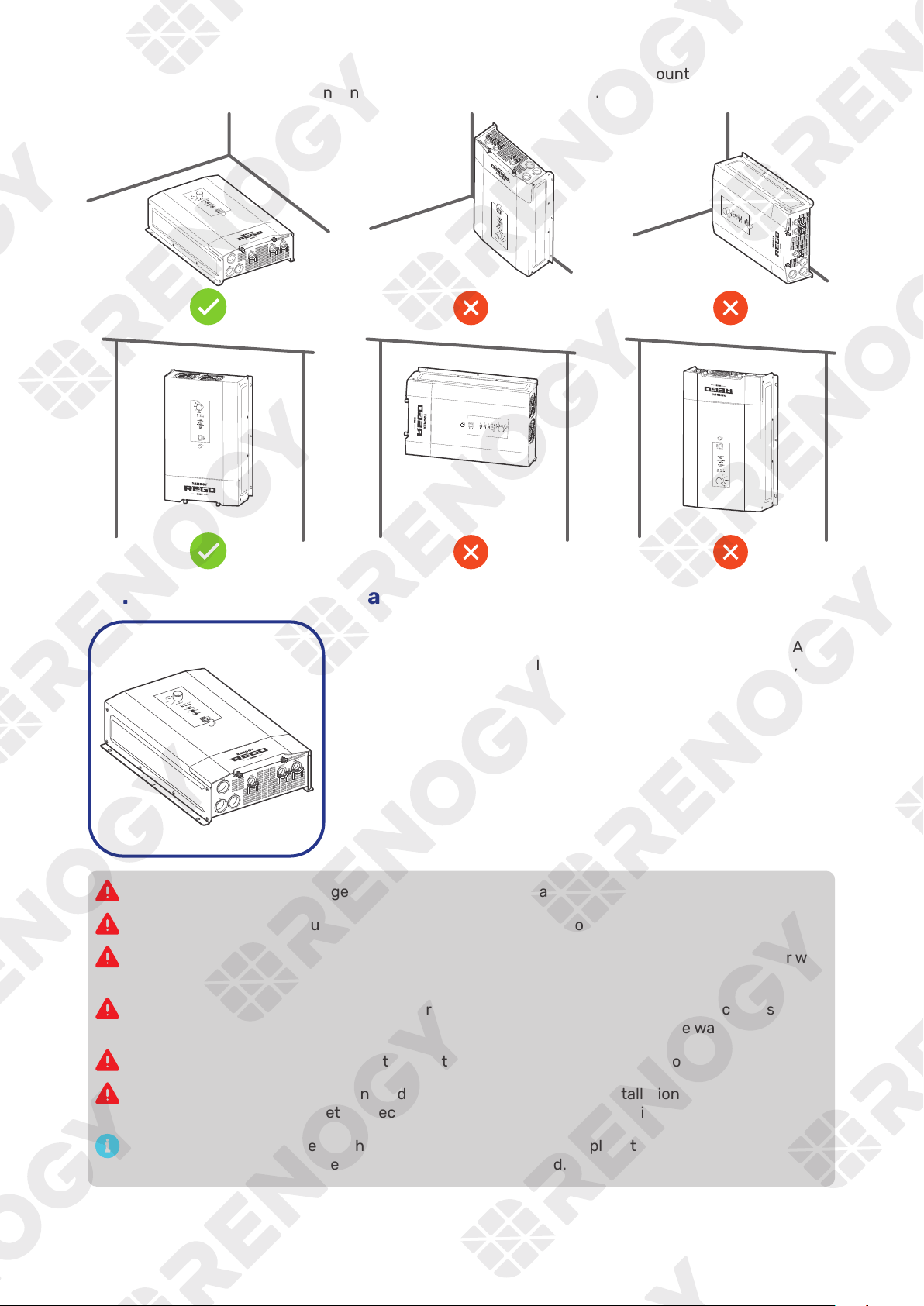
To ensure good ventilation and optimal system performance, we recommend mounting the inverter
charger vertically (terminals down) on a wall or horizontally on the floor.
3.2. Check the Inverter Charger
1. Inspect the inverter charger for any visible damage including
cracks, dents, deformation, and other visible abnormalities. All
connector contacts shall be clean, free of dirt and corrosion, and
dry.
Do not use the inverter charger if there is any visible damage.
Do not puncture, drop, crush, penetrate, shake, strike, or step on the inverter charger.
There are no serviceable parts in the inverter charger. Do not open, dismantle, repair, tamper with,
or modify the inverter charger.
damage to the inverter charger and other connected devices, thus voiding the warranty.
Do not touch the connector contacts while the inverter charger is in operation.
Wear proper protective equipment and use insulated tools during installation and operation. Do
not wear jewelry or other metal objects when working on or around the inverter charger.
Do not dispose of the inverter charger as household waste. Comply with local, state, and federal
laws and regulations and use recycling channels as required.
— 8 —
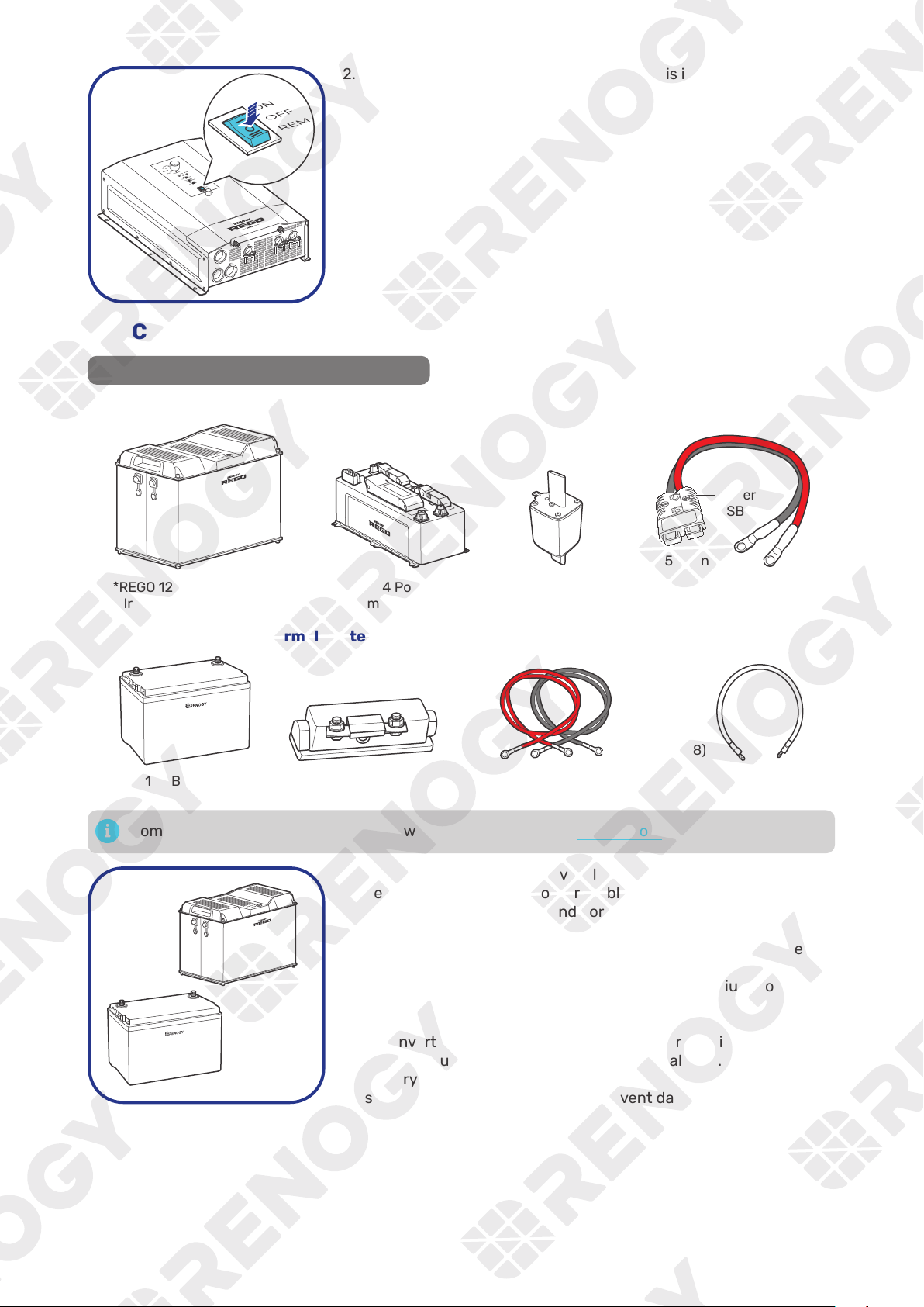
2. Ensure the On/Off/Remote Power Switch is in the OFF position.
3.3. Check the Battery
Recommended Components & Accessories
█
Battery Scenario A: REGO Battery Kit
*REGO 4 Ports 400A
System Combiner Box
*REGO 12V 400Ah Lithium
Iron Phosphate Battery
*NH2 Fuse
(400A)
*Anderson Adapter
Cable (4/0 AWG)
Anderson
SB350
5/16 in (M8)
DC- DC Char ger
Inv ert er
█
Battery Scenario B: Normal Battery Kit
+
-
*ANL Fuse (400A)
Fuse Cable
(4/0 AWG)
*12V Battery
Battery Adapter Cables
(4/0 AWG) × 2
5/16 in (M8)
Components and accessories marked with “*” are available on renogy.com.
+
-
1. Inspect the battery for any visible damage including cracks,
dents, deformation, and other visible abnormalities. All terminals
shall be clean, free of dirt and corrosion, and dry.
The inverter charger can only be connected to deep-cycle gel-
sealed lead-acid batteries (GEL), flooded lead-acid batteries
(FLD), sealed lead-acid batteries (SLD/AGM) or lithium iron
phosphate batteries (LI).
The inverter charger provides overcurrent protection by detecting
the DC input current from the battery in real time. When the
battery input reaches 400A, the inverter charger automatically
shuts down the battery input to prevent damage caused by
excessively high current.
— 9 —
Do not use the battery if there is any visible damage. Do not touch the exposed electrolyte or
powder if the battery housing is damaged.
When being charged, the battery may give off explosive gas. Make sure there is good ventilation.
Take care to use a high-capacity lead-acid battery. Be sure to wear protective goggles. If
Combine batteries in parallel or in series as needed. Prior to installing the inverter charger, ensure
all battery groups are installed properly.
Read the user manual of the battery in use carefully.
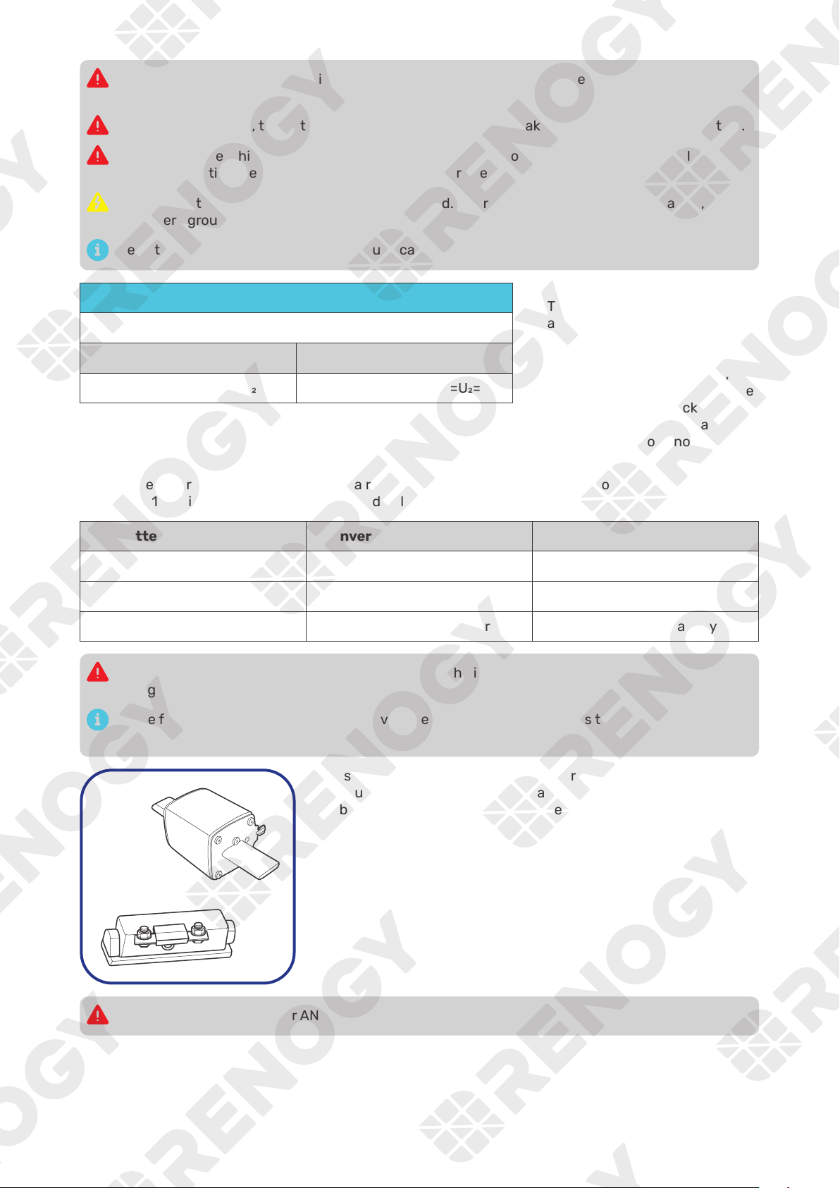
Battery or Battery Bank System Voltage
Battery or Battery Bank System Voltage = System Voltage U
Batteries in Series Batteries in Parallel
System Voltage U: U+U+U System Voltage U: U=U=U
2. Check battery system voltage.
This inverter charger supports
a maximum system voltage
of 17V. Read the user manual
of the specific battery for
battery voltage parameters,
and calculate the voltage of the
battery or battery pack system
according to the formula to
ensure that it does not exceed
17V.
The inverter charger operates normally at a range between 11V and 15.8V and allows a battery input
from 9V to 17V with operating status specified below:
Battery Input Voltage Inverter Charger Status Solution
9V < Voltage < 11V May fails to detect the battery Charge the battery immediately
Operates normally N/A
15.8V < Voltage < 17V Trigger overvoltage alarm Discharge the battery
Do not connect batteries rating higher than 17V to the inverter. Doing so will damage the inverter
charger.
In the formula, U represents the battery voltage, and 1, 2, or 3 represents the battery number
respectively.
3. Inspect the NH2 Fuse or ANL Fuse for any visible damage
including cracks, dents, deformation, and other visible
abnormalities. All terminals shall be clean, free of dirt and
corrosion, and dry.
Do not use the NH2 Fuse or ANL Fuse if there is any visible damage.
— 10 —
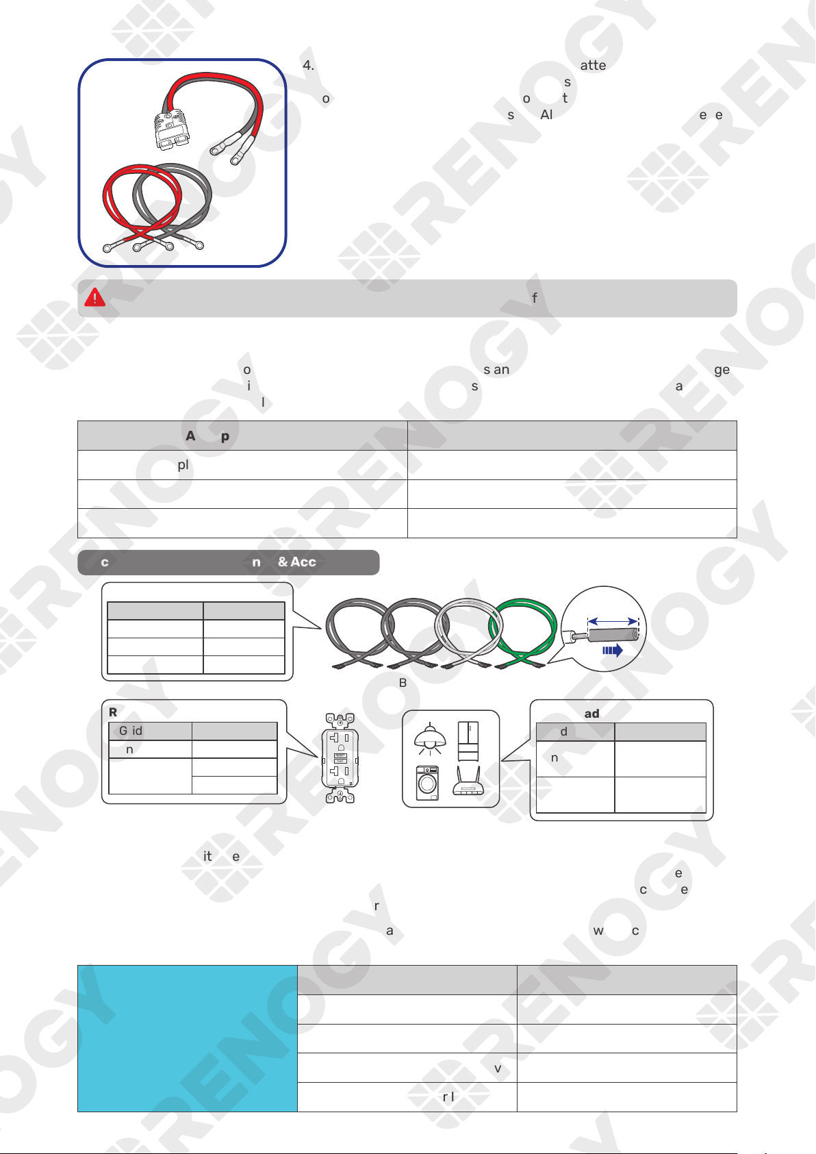
4. Inspect the Anderson Adapter Cable or Battery Adapter Cables
for any visible damage including cracks, dents, deformation, and
other visible abnormalities. All connector contacts shall be clean,
dry, and free of dirt and corrosion. All ring terminals are fastened
to the cables.
Do not use the Anderson adapter cable or battery adapter cables if there is any visible damage.
3.4. Check the AC Loads (Appliances)
It works seamlessly with both 120V and 240V grid power systems and outputs 120V or 240V AC voltage
in accordance with the AC input voltage. Choose proper accessories and cables based on the rated
voltage of the connected AC loads (appliances).
AC Input Voltage AC Output Voltage
Split-phase 120V/240V 120V/240V
Single-phase 120V 120V
0V (when grid power is unavailable) 120V
Recommended Components & Accessories
Ground Fault Circuit
Interrupter (GFCI)
AC Loads
Recommended GFCI Spec
Grid Power Ratings
Unavailable
Available
Total Load Power
Grid Power Ratings
Unavailable
Available
Recommended Cable Size
Cable Length Cable Size
A ground fault circuit interrupter, or GFCI, is a device that helps protect people from electric shock
by de-energizing a circuit or part of a circuit within a specified time if a current to ground exceeds a
predetermined value that is less than that required to operate the overcurrent device (circuit breaker or
fuse) on the service circuit. GFCIs are typically required in wet or damp locations.
The following table lists GFCIs that meet specifications and will function properly when connected to
the AC Outlets of the inverter charger.
Tested GFCI Models
Manufacturer Model Number
Cooper Wiring Devices SGF20
Leviton Mfg Co lnc GFNT2
Hubbell Inc Wiring Device Dev GFRST20
Pass & Seymour Inc 2097
— 11 —
Risk of electrical shock. Use only ground-fault circuit interrupters [receptacle(s) or circuit
breaker(s)] compatible with your inverter charger.
GFCIs shall be installed in a recreational vehicle’s wiring system to protect all branch circuits.
For details on how to connect loads and the inverter charger to the GFCI, read the user manual of
the specific GFCI.
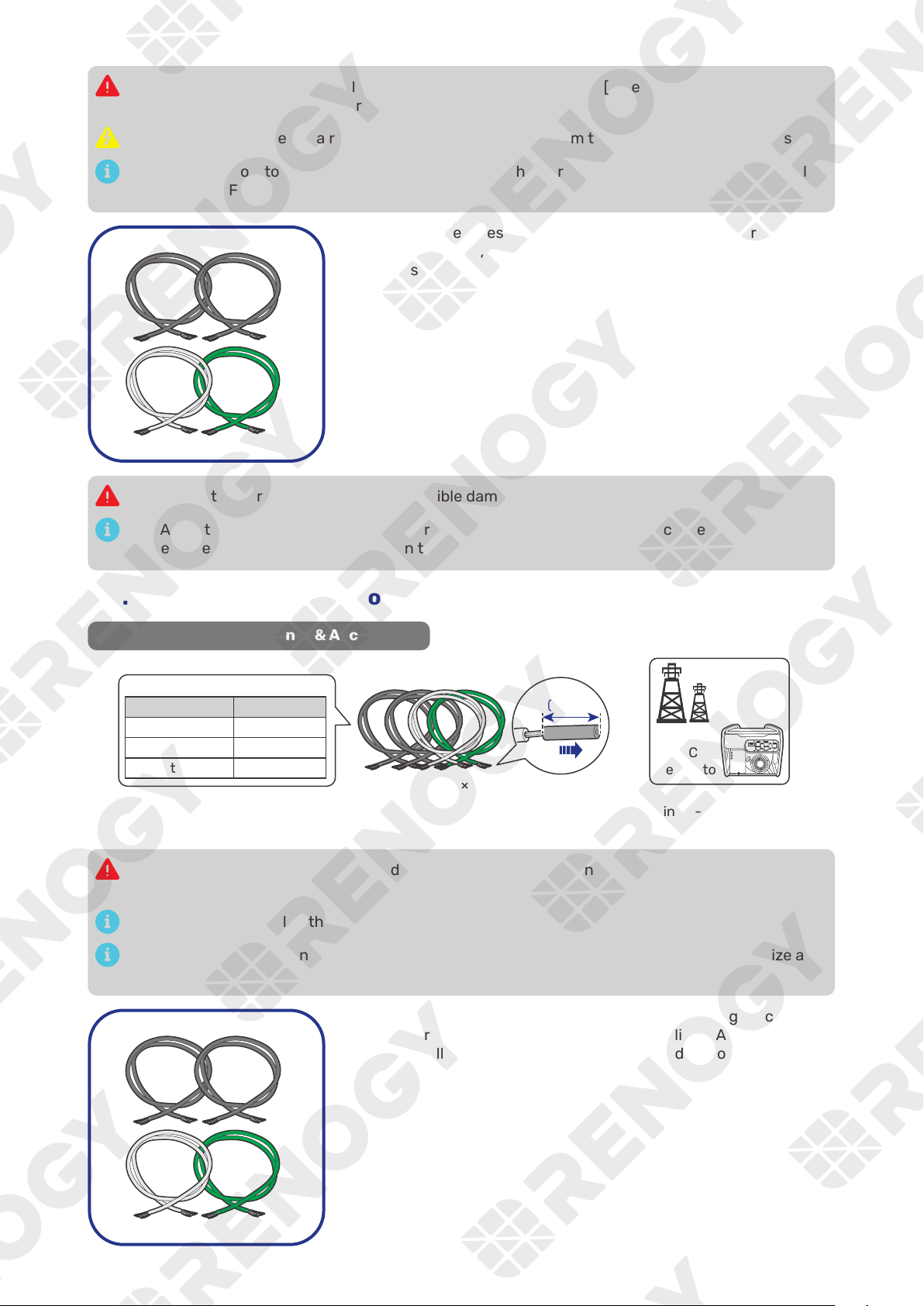
Inspect the Bare Wires for any visible damage including cracks,
dents, deformation, and other visible abnormalities. All connector
contacts shall be clean, dry, and free of dirt and corrosion.
Do not use the bare wires if there is any visible damage.
The AC Output Port has an inner diameter of 0.79 in (20 mm). Properly select the AC cable size
and ensure that four bare wires can run through the grommet at the same time.
3.5. Check the AC Generator or the Grid (Optional)
Recommended Components & Accessories
Bare Wires × 4
(10 mm)
0.39 in
Grid Power
(Single-phase 120V or
Split-phase 120V/240V)
Recommended Cable Size
Cable Length Cable Size
0 ft to 10 ft 6 AWG
11 ft to 20 ft 4 to 6 AWG
21 ft to 30 ft 4 AWG
AC
Generator
Risk of electric shock! Ensure the grid or the AC generator is turned off before connecting them
to the inverter charger.
Read the user manual of the AC generator before the installation.
The AC Input Port has an inner diameter of 0.79 in (20 mm). Properly select the AC cable size and
ensure that four bare wires can run through the grommet at the same time.
Inspect the Bare Wires for any visible damage including cracks,
dents, deformation, and other visible abnormalities. All connector
contacts shall be clean, dry, and free of dirt and corrosion.
— 12 —
Do not use the bare wires if there is any visible damage.
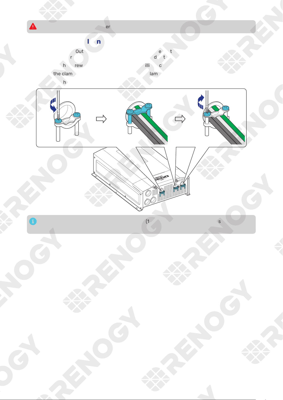
3.6. How to Properly Install Cable Clamps?
The AC Input Port, AC Output Port, and COM Port are equipped with cable clamps to ensure that the
wiring connections remain secure and do not come loose due to vibrations.
Step 1: Loosen the screws on a cable clamp with a Phillips Screwdriver.
Step 2: Lift the clamp, and run the cables through the clamp.
Step 3: Secure the clamp by fastening the screws.
14.16 in·lbs
(1.6 N·m)
The screw torque of a cable clamp is 14.16 in·lbs (1.6 N·m). Do not overtighten the screws to
prevent damage.
— 13 —
4. Installation
To ensure safe and efficient operation of the inverter charger and to avoid potential damage or hazards,
always follow the installation instructions in the sequence described in this manual.
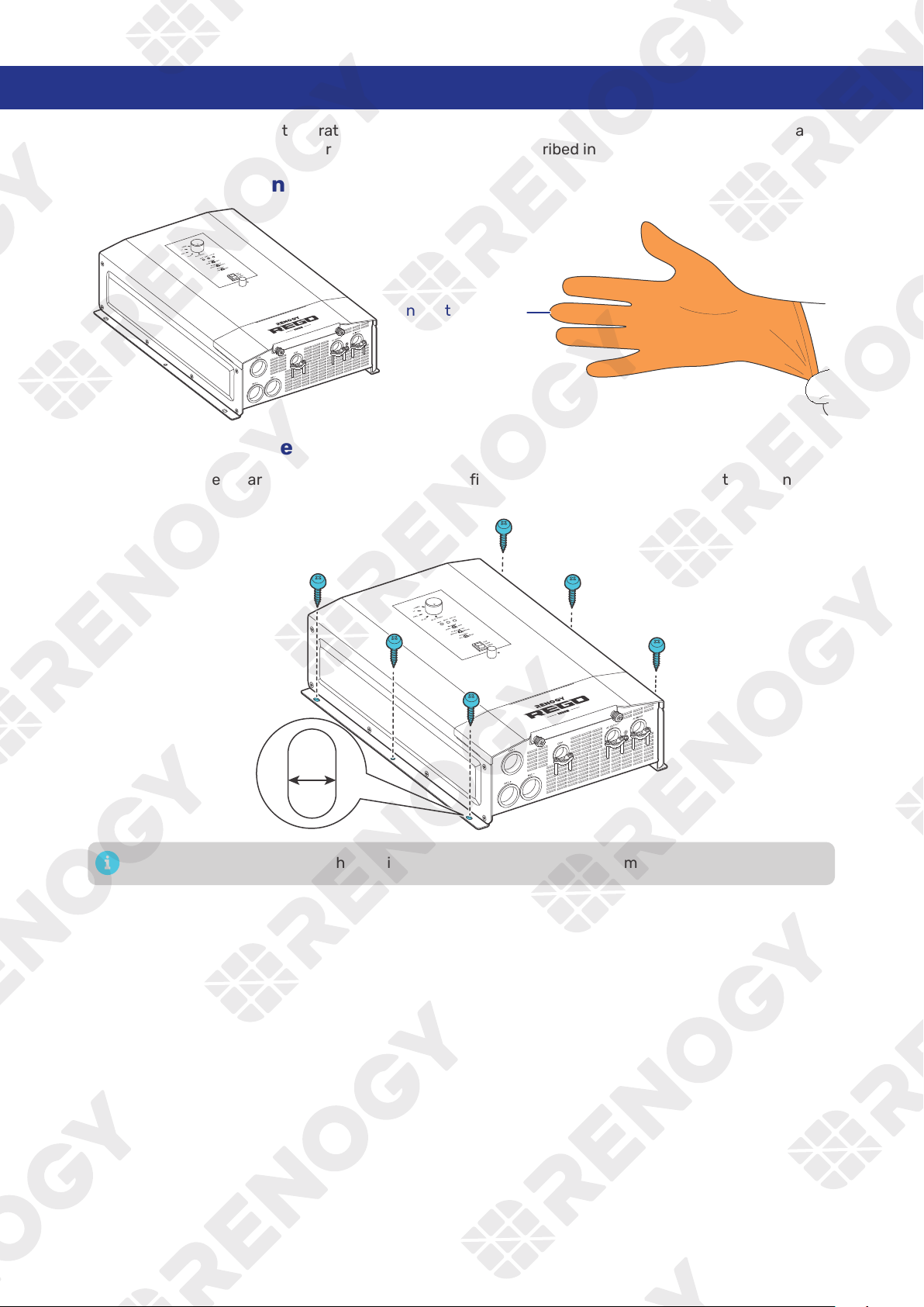
4.1. Wear Insulating Gloves
Insulating Gloves
4.2. Mount the Inverter Charger
Secure the inverter charger to the installation site by fixing self-tapping screws through the mounting
holes.
0.27 in
(7 mm)
Make sure that the inverter charger is installed firmly to prevent it from falling off.
— 14 —
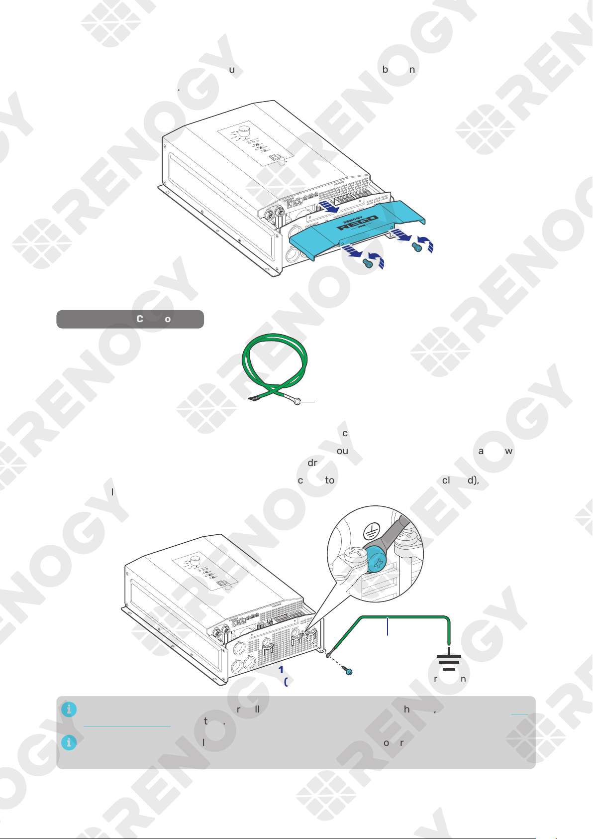
4.3. Remove the Cover
Step 1: Turn the two Cover Screws counterclockwise either by hand or by using a Phillips screwdriver.
Step 2: Remove the Cover.
4.4. Ground the Inverter Charger
Recommended Components
3/16 in (M4)
Grounding Cable (6 AWG)
Step 1: Remove the screw on the Ground Port with a Phillips Screwdriver.
Step 2: Connect the Grounding Cable Ring Terminal to the grounding port of the inverter charger with
the removed screw by using the Phillips Screwdriver.
Step 3:
Connect the bare wire end of the grounding cable to a grounding rod (not included), if
applicable.
Grounding
Grounding Cable
14.16 in·lbs
(1.6 N·m)
When the GFCI fails to operate normally after grounding the inverter charger, please refer to “5.1.
N-G Bonding Relay” for details.
The screw torque of a cable clamp is 14.16 in·lbs (1.6 N·m). Do not overtighten the screws to
prevent damage.
— 15 —
The DC Grounding system is sometimes referred to as the earth ground or another designated
ground. In an RV Setting, the metal frame of the RV could be the designated ground. A common
ground should be used to bond the inverter charger, negative bus bar, and negative battery
terminal together, if applicable.
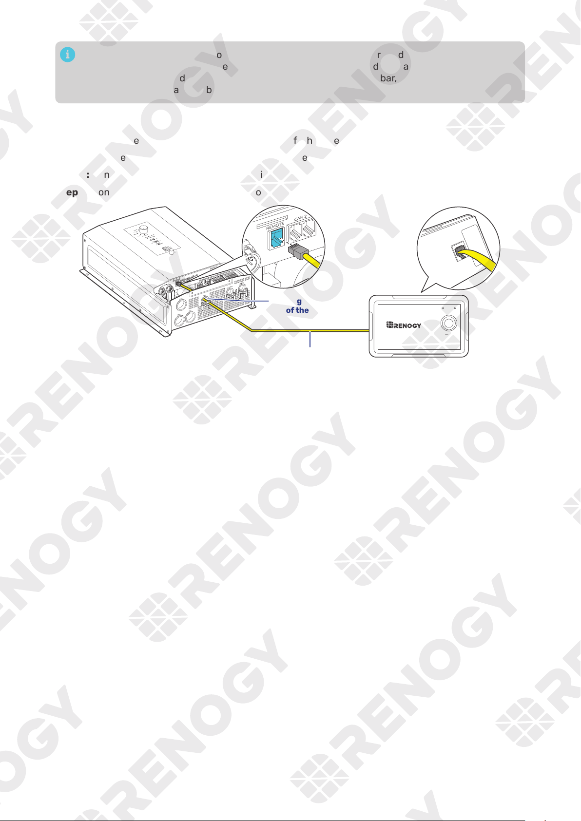
4.5. Install a Wired Remote Control
You can use a Wired Remote Control to power on or off the inverter charger remotely.
Step 1:
Run the RJ12 Cable through the grommet of the COM Port.
Step 2: Connect the RJ12 connector to the Wired Remote Port on the inverter charger.
Step 3: Connect the other end of the cable to the Wired Remote Control.
RJ12 Cable
ON ERR
RMS-P2
Through the grommet
of the COM Port
— 16 —
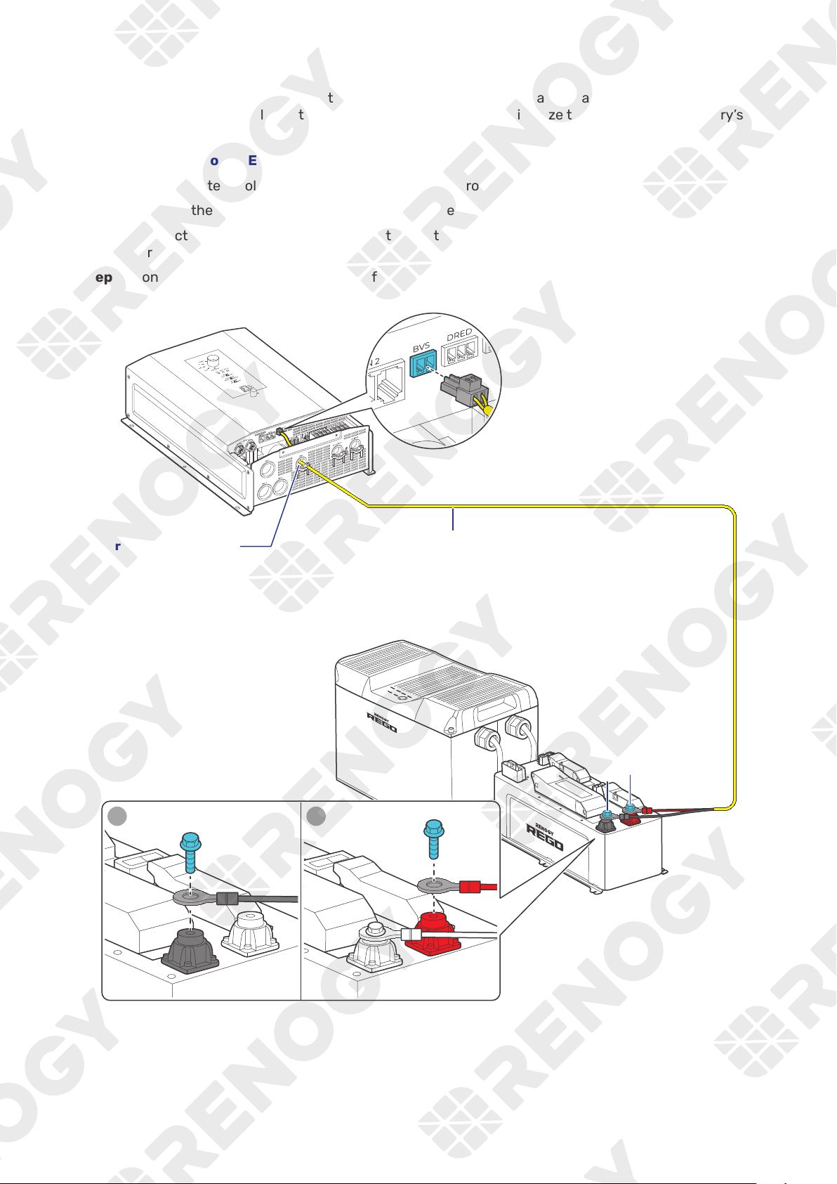
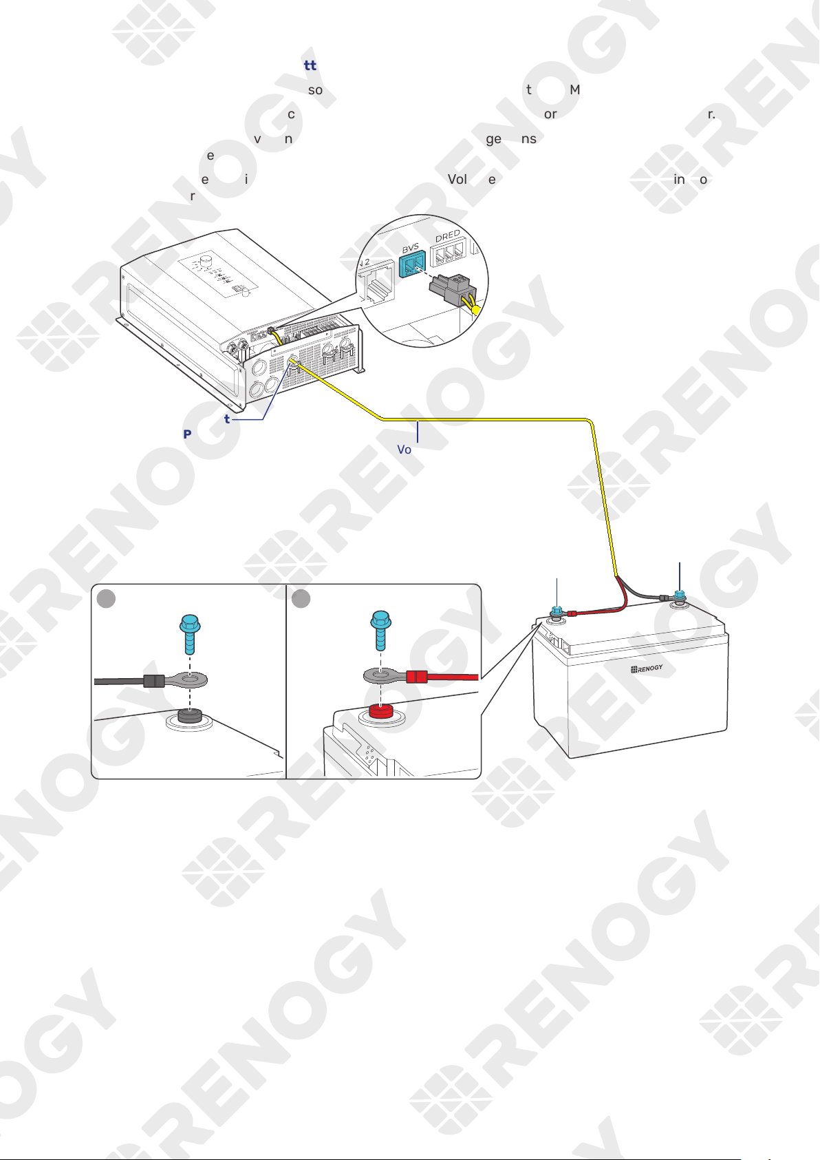
4.6. Install a Battery Voltage Sensor
The Battery Voltage Sensor measures the battery voltage during discharging and compensates for any
voltage drop across the cables at the battery terminal. This helps minimize the impact on the battery’s
operational voltage.
█
Battery Scenario A: REGO Battery Kit
Step 1:
Run the Battery Voltage Sensor cable through the grommet of the COM Port.
Step 2: Connect the terminal block to the Battery Voltage Sensor (BVS) Port on the inverter charger.
Step 3: Connect the Negative Ring Terminal of the Battery Voltage Sensor to the Negative Insert
Terminal on the REGO 4 Ports 400A System Combiner Box.
Step 4:
Connect the Positive Ring Terminal of the Battery Voltage Sensor to the Positive Insert Terminal
on the REGO 4 Ports 400A System Combiner Box.
+
-
Battery Voltage Sensor
Through the grommet
of the COM Port
1 2
— 17 —
█
Battery Scenario B: Normal Battery Kit
Step 1:
Run the Battery Voltage Sensor cable through the grommet of the COM Port.
Step 2: Connect the terminal block to the Battery Voltage Sensor (BVS) Port on the inverter charger.
Step 3: Connect the Negative Ring Terminal of the Battery Voltage Sensor to the Negative Terminal on
the 12V battery.
Step 4:
Connect the Positive Ring Terminal of the Battery Voltage Sensor to the Positive Terminal on the
12V battery.
+
-
+
-
Battery Voltage Sensor
Through the grommet
of the COM Port
1 2
-
+
— 18 —
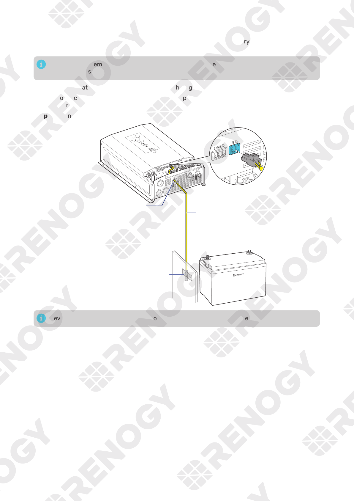
4.7. Install a Battery Temperature Sensor
The temperature sensor measures the surrounding temperature of the battery and compensates the
floating charge voltage when the battery temperature is low.
Do not use the temperature sensor on a LiFePO4 (LFP) battery which comes with a battery
management system (BMS).
Step 1:
Run the Battery Temperature Sensor cable through the grommet of the COM Port.
Step 2: Connect the terminal block to the Battery Temperature Sensor (BTS) Port on the inverter
charger.
Step 3:
Mount the sensor securely at a suitable location in close proximity to the battery.
+
-
Battery Temperature Sensor
Mount the sensor securely
at a suitable location in
close proximity to the battery.
Through the grommet
of the COM Port
Never mount the temperature sensor on the battery to prevent false overtemperature alarms.
— 19 —
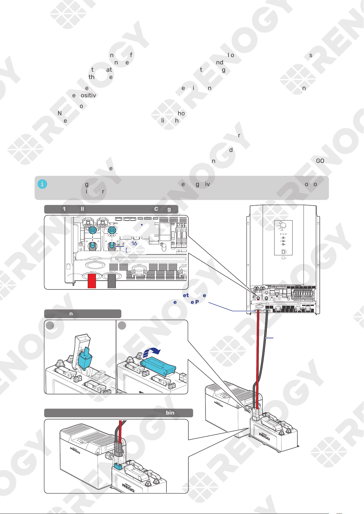
4.8. Connect the Inverter Charger to a Battery
█
Battery Scenario A: REGO Battery Kit
Step 1:
Remove the retaining nut from the Battery Negative Terminal on the inverter charger by using
a Socket Wrench. Run the negative lug (in black) of the Anderson Adapter Cable through the
grommet of the Battery Negative Port, and connect the negative lug to the Battery Negative
Terminal with the retaining nut.
Step 2:
Repeat the actions on the Battery Positive Terminal on the inverter charger to finish connection
on the positive end.
Step 3: Lift the operating handle to open the cover of the REGO 4 Ports 400A System Combiner Box
NH2 Fuse Switch Disconnector, press and hold the release tab on the inside of the cover, locate
the slots on the inside of the cover, slide the gripping lugs of the NH2 Fuses into the slots, and
release the release tab.
Ensure the NH2 Fuse is installed tightly prior to closing the cover of the NH2 Fuse Switch
Disconnector.
Press the cover firmly to ensure that the NH2 Fuse is engaged.
Step 4:
Insert the Anderson SB350 connectors to the Anderson 350 Connector (Inverter) on the REGO
4 Ports 400A System Combiner Box.
The retaining nut torque of the Battery Positive/Negative Terminal is 70.8 in·lbs (8 N·m). Do not
overtighten it to prevent damage.
N L2
AC OUT
L1 N L2
AC IN
L1
BAT-
BAT+
STEP-1 Install the Cable on the Inverter Charger
STEP-3 Install the Cable on the System Combiner Box
Through the grommet of the
Battery Positive Port and Battery Negative Port
N
AC OUT
BAT-
BAT+
STEP-2 Install an NH2 Fuse
Anderson
Adapter
Cable
1
Inv ert er
Syst
Inv ert er
System C
om bine r Bo
2
5/16 in
(M8)
70.8 in·lbs
(8 N·m)
— 20 —
█
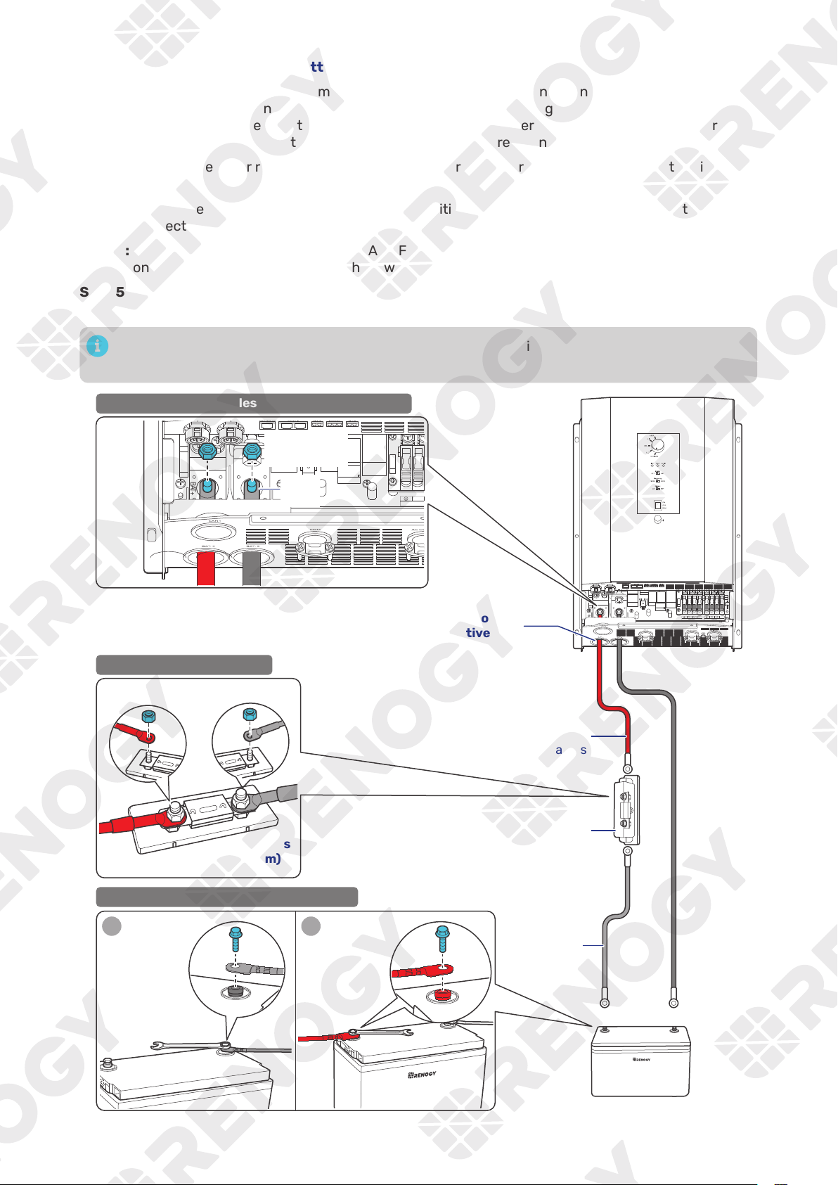
Battery Scenario B: Normal Battery Kit
Step 1:
Remove the retaining nut from the Battery Negative Terminal on the inverter charger by using
a Socket Wrench. Run the Negative Battery Adapter Cable through the grommet of the Battery
Negative Port of the inverter charger, and connect the ring terminal of the Negative Battery
Adapter Cable to the Battery Negative Terminal with the retaining nut.
Step 2:
Connect the other ring terminal of Negative Battery Adapter Cable to the negative terminal of
the battery.
Step 3:
Repeat the actions in Step 1 on the Battery Positive Terminal on the inverter charger to finish
connection on the positive end.
Step 4:
Remove the retaining nuts from the ANL Fuse, connect the Positive Battery Adapter Cable to
one end of the ANL Fuse, and fix them with one retaining nut.
Step 5:
Connect the ANL Fuse to the positive terminal of the battery via the Fuse Cable, and fix the fuse
cable on the ANL Fuse with the other retaining nut.
The retaining nut torque of the Battery Positive/Negative Terminal is 70.8 in·lbs (8 N·m). Do not
overtighten it to prevent damage.
N L2
AC OUT
L1 N L2
AC IN
L1
BAT-
BAT+
STEP-1 Install the Cables on the Inverter Charger
STEP-2 Install an ANL Fuse
+
-
12V Battery
Battery
Adapter
Cables
Fuse
Cable
ANL
Fuse
(400A)
-
+
1
2
12
+
-
+
-
1 2
STEP-3 Install the Cables on the Battery
N
AC OUT
BAT-
BAT+
5/16 in
(M8)
Through the grommet of the
Battery Positive Port and Battery Negative Port
70.8 in·lbs
(8 N·m)
70.8 in·lbs
(8 N·m)
+
-
— 21 —
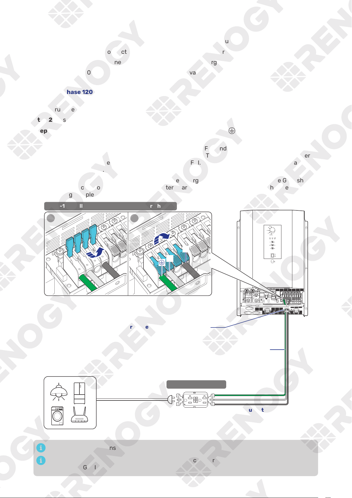
4.9. Connect the Inverter Charger to AC Loads (Appliances)
For split-phase 120V/240V grid systems where AC IN L1, L2, and N are used:
z
When the AC output is connected to L1, L2, and N, the inverter charger outputs 240V.
z
When the AC output is connected to L1 and N, the inverter charger outputs 120V.
For single-phase 120V grid systems or when there is no available grid power, the inverter charger
outputs 120V.
█
Single-phase 120V
Step 1:
Strip some insulation (0.39 in/10 mm) off each of the three bare wires with a wire stripper, and
run the three bare wires through the grommet of the AC Output Port on the inverter charger.
Step 2:
Push up the switches of the wire harness retainer of the AC Output Terminals.
Step 3: Connect the bare wires to the live (L1), neutral (N) and ground (
) terminals respectively on
the inverter charger.
Step 4:
Locate the live, neutral, and ground terminals on the GFCI, and connect the other ends of
the bare wires to the respective terminals on the GFCI. The L1 terminal of the inverter charger
should be connected to the live terminal on the GFCI. The same rules apply to the neutral and
ground terminals.
Step 5:
To ensure optimal performance of the inverter charger, it is recommended that the GFCI should
be connected to AC loads after the inverter charger is securely powered on with necessary
wiring completed.
N L2
AC OUT
L1 N L2
AC IN
L1
BAT-
BAT+
AC Loads (120V)
1 2
STEP-1 Install Bare Wires on the Inverter Charger
STEP-2 Install a GFCI
L1
N
Bare Wires
Through the grommet of the AC Output Port
120V Output
Tug on bare wires to ensure firm connection.
For details on how to connect loads and the inverter charger to the GFCI, read the user manual of
the specific GFCI.
— 22 —
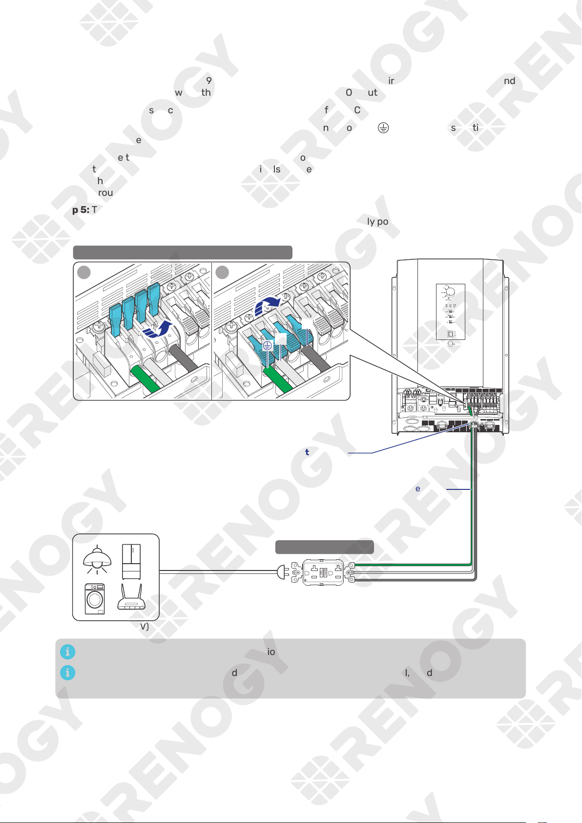
█
Split-phase 120V/240V
120V output wiring:
Step 1:
Strip some insulation (0.39 in/10 mm) off each of the three bare wires with a wire stripper, and
run the three bare wires through the grommet of the AC Output Port on the inverter charger.
Step 2:
Push up the switches of the wire harness retainer of the AC Output Terminals.
Step 3: Connect the bare wires to the live (L1), neutral (N) and ground (
) terminals respectively on
the inverter charger.
Step 4:
Locate the live, neutral, and ground terminals on the GFCI, and connect the other ends of
the bare wires to the respective terminals on the GFCI. The L1 terminal of the inverter charger
should be connected to the live terminal on the GFCI. The same rules apply to the neutral and
ground terminals.
Step 5:
To ensure optimal performance of the inverter charger, it is recommended that the GFCI should
be connected to AC loads after the inverter charger is securely powered on with necessary
wiring completed.
N L2
AC OUT
L1 N L2
AC IN
L1
BAT-
BAT+
AC Loads (120V)
1 2
STEP-1 Install Bare Wires on the Inverter Charger
STEP-2 Install a GFCI
L1
N
Bare Wires
Through the grommet of the AC Output Port
120V Output
Tug on bare wires to ensure firm connection.
For details on how to connect loads and the inverter charger to the GFCI, read the user manual of
the specific GFCI.
— 23 —
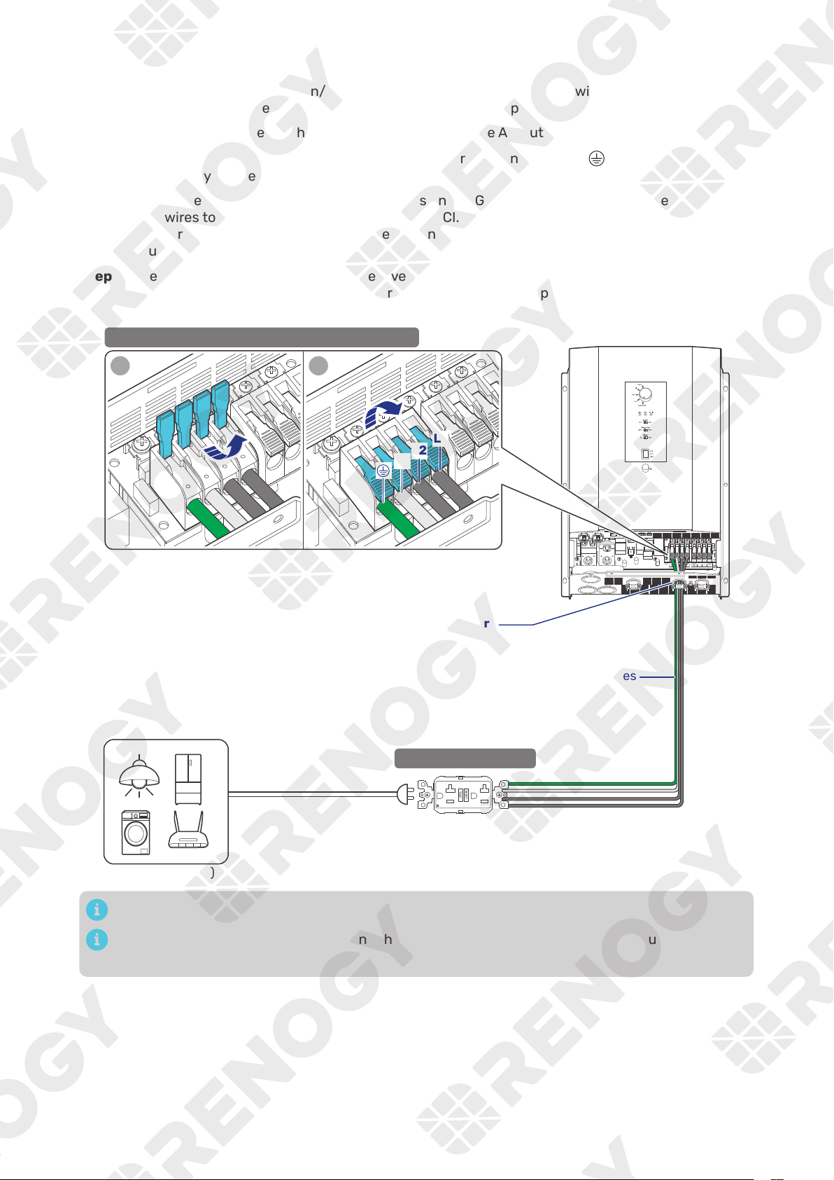
240V output wiring:
Step 1:
Strip some insulation (0.39 in/10 mm) off each of the four bare wires with a wire stripper, and
run the four bare wires through the grommet of the AC Output Port on the inverter charger.
Step 2:
Push up the switches of the wire harness retainer of the AC Output Terminals.
Step 3: Connect the bare wires to the live (L1 and L2), neutral (N) and ground (
) terminals
respectively on the inverter charger.
Step 4:
Locate the live, neutral, and ground terminals on the GFCI, and connect the other ends of the
bare wires to the respective terminals on the GFCI. The L1 and L2 terminals of the inverter
charger should be connected to the live terminal on the GFCI. The same rules apply to the
neutral and ground terminals.
Step 5:
To ensure optimal performance of the inverter charger, it is recommended that the GFCI should
be connected to AC loads after the inverter charger is securely powered on with necessary
wiring completed.
N L2
AC OUT
L1 N L2
AC IN
L1
BAT-
BAT+
AC Loads (240V)
1 2
STEP-1 Install Bare Wires on the Inverter Charger
STEP-2 Install a GFCI
L1
N
L2
Bare Wires
Through the grommet of the AC Output Port
240V Output
Tug on bare wires to ensure firm connection.
For details on how to connect loads and the inverter charger to the GFCI, read the user manual of
the specific GFCI.
— 24 —
4.10. Connect the Inverter Charger to the Grid
The connection of AC IN ports vary depending on the connected grid systems. For single-phase 120V
grid systems, only AC IN L1 and N ports are used for the input. For split-phase 120V/240V grid systems,
AC IN L1, L2, and N ports are used for the input.
Do not parallel the inverter charger with other AC input sources to avoid damage.
The inverter charger provides overcurrent protection by detecting the AC input current from
the grid or a generator in real time. When the AC input reaches 30A, the inverter charger
automatically shuts down the AC input to prevent damage caused by excessively high current.
You can customize the overcurrent protection threshold on the DC Home app. Maximum allowed
threshold: 50A.
█
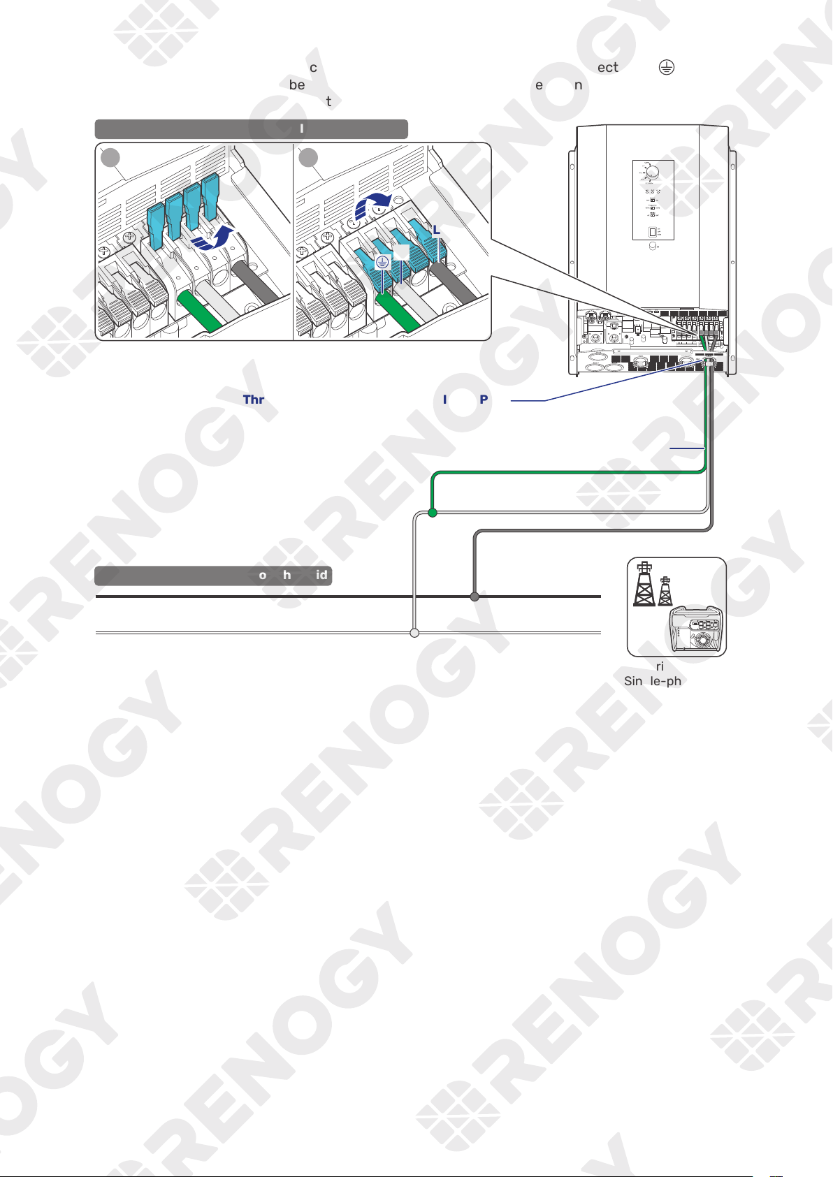
Single-phase 120V
Step 1:
Strip some insulation (0.39 in/10 mm) off each of the three bare wires with a wire stripper, and
run the three bare wires through the grommet of the AC Input Port on the inverter charger.
Step 2:
Push up the switches of the wire harness retainer of the AC Input Terminals.
Step 3: Connect the bare wires to the live (L1), neutral (N) and ground (
) terminals respectively on
the inverter charger.
Step 4:
Locate the live, neutral, and ground terminals on the grid, and connect the other ends of the
bare wires to the respective terminals on the grid. The L1 terminal of the inverter charger should
be connected to the live terminal on the grid. The same rules apply to the neutral and ground
terminals.
Grid Power
(Single-phase 120V)
L
N
PE
STEP-2 连接信号线.
STEP-2 Install Bare Wires on the Grid
N L2
AC OUT
L1 N L2
AC IN
L1
BAT-
BAT+
120V Input
Through the grommet of the AC Input Port
STEP-1 Install Bare Wires on the Inverter Charger
1 2
L1
N
Bare Wires
Tug on bare wires to ensure firm connection.
— 25 —
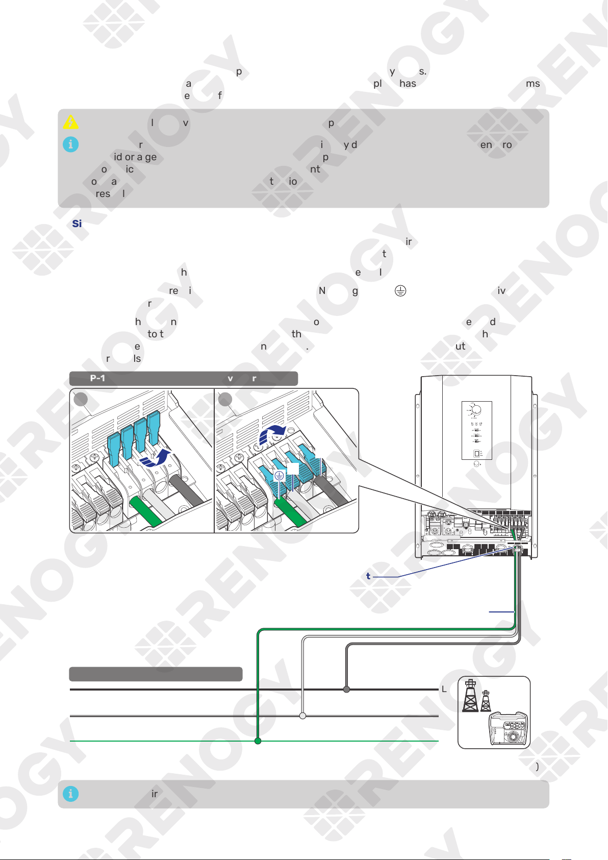
If there is no available grid contact, connect the ground bare wire (one end connecting to
) to the N
bare wire as shown in the figure below. Failure to follow this step may result in charging/discharging
issues with grid power, along with fault alarms.
Grid Power
(Single-phase 120V)
L
N
STEP-2 连接信号线.
STEP-2 Install Bare Wires on the Grid
N L2
AC OUT
L1 N L2
AC IN
L1
BAT-
BAT+
120V Input
Through the grommet of the AC Input Port
STEP-1 Install Bare Wires on the Inverter Charger
1 2
L1
N
Bare Wires
— 26 —
█
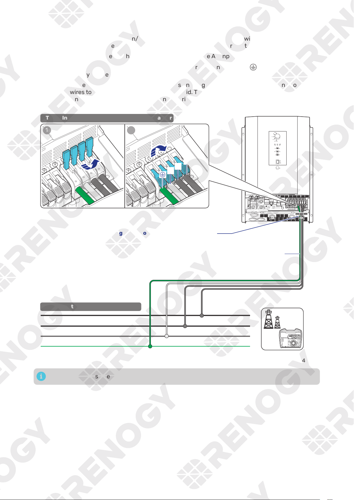
Split-phase 120V/240V
Step 1:
Strip some insulation (0.39 in/10 mm) off each of the four bare wires with a wire stripper, and
run the four bare wires through the grommet of the AC Input Port on the inverter charger.
Step 2:
Push up the switches of the wire harness retainer of the AC Input Terminals.
Step 3: Connect the bare wires to the live (L1 and L2), neutral (N) and ground (
) terminals
respectively on the inverter charger.
Step 4:
Locate the live, neutral, and ground terminals on the grid, and connect the other ends of the
bare wires to the respective terminals on the grid. The L1 terminal of the inverter charger should
be connected to the live terminal (L1) on the grid. The same rules apply to the L2, neutral, and
ground terminals.
Grid Power
(Split-phase 120V/240V)
L1
N
PE
STEP-2 连接信号线.
STEP-2 Install Bare Wires on the Grid
L2
N L2
AC OUT
L1 N L2
AC IN
L1
BAT-
BAT+
Through the grommet of the AC Input Port
STEP-1 Install Bare Wires on the Inverter Charger
1 2
L1
N
L2
Bare Wires
Tug on bare wires to ensure firm connection.
— 27 —
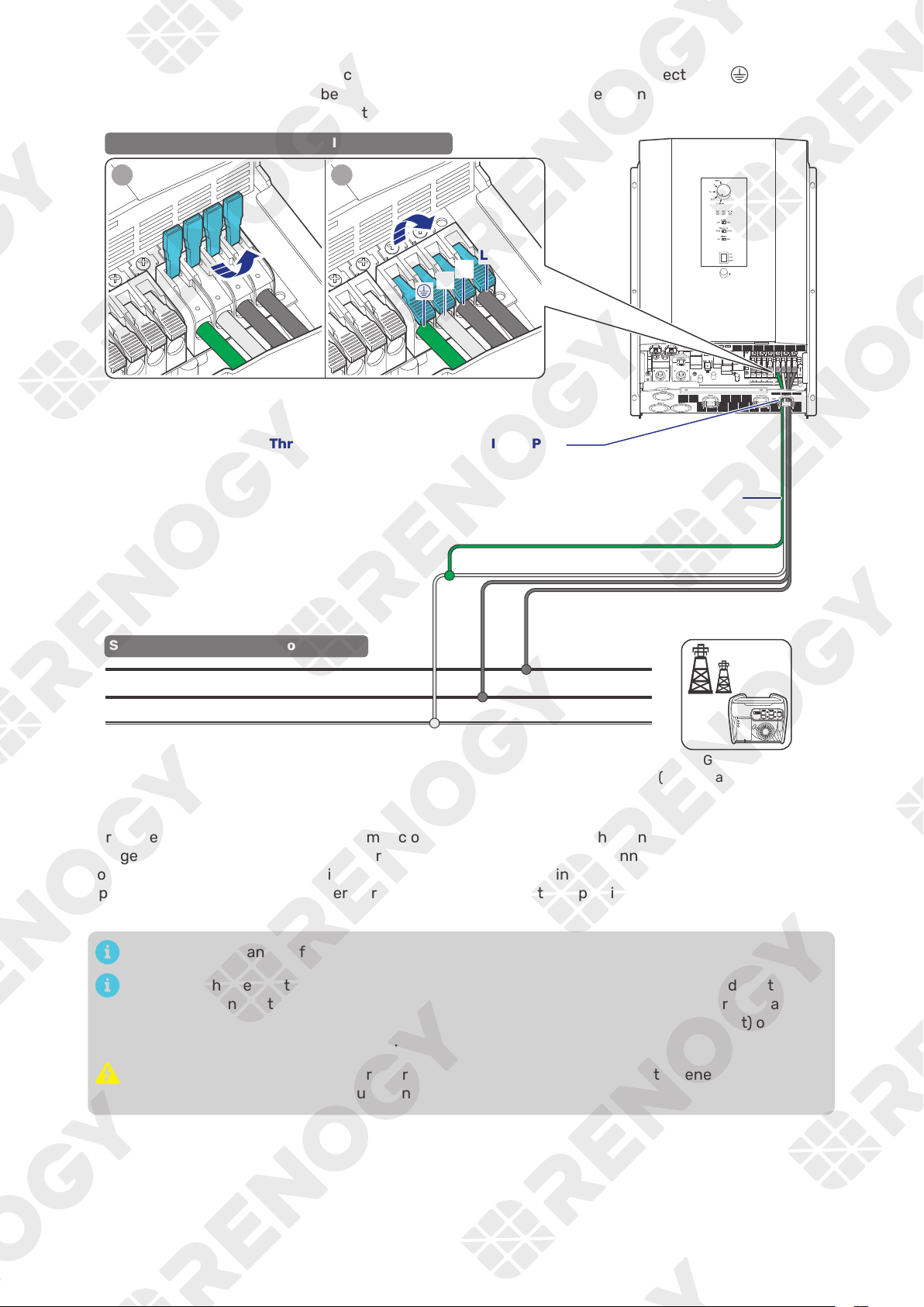
If there is no available grid contact, connect the ground bare wire (one end connecting to
) to the N
bare wire as shown in the figure below. Failure to follow this step may result in charging/discharging
issues with grid power, along with fault alarms.
Grid Power
(Split-phase 120V/240V)
L1
N
STEP-2 连接信号线.
STEP-2 Install Bare Wires on the Grid
L2
N L2
AC OUT
L1 N L2
AC IN
L1
BAT-
BAT+
Through the grommet of the AC Input Port
STEP-1 Install Bare Wires on the Inverter Charger
1 2
L1
N
L2
Bare Wires
█
Automatic Generator Start
For AC Generators supporting the automatic on/off function, connect the generator to the inverter
charger. If the battery voltage reaches or falls below the Low Voltage Reconnect value (when a Battery
Voltage Sensor are involved), the inverter charger will send a 5-minute start signal to the generator.
Upon receiving the signal, the generator will automatically start and provide power to the battery and
loads.
Read the user manual of the AC Input source carefully before connection.
Make sure the generator can automatically start or stop. Identify NC (normally closed contact), NO
(normally open contact), and C (common static contact) of the generator and ensure signal lines
are connected properly. Some generators only have NC and C (common static contact) or NO and
C. You can connect them on demand.
Do not install the inverter charger near any generator supporting automatic generator on/off
because these generators exhaust dangerous fumes in operation.
— 28 —
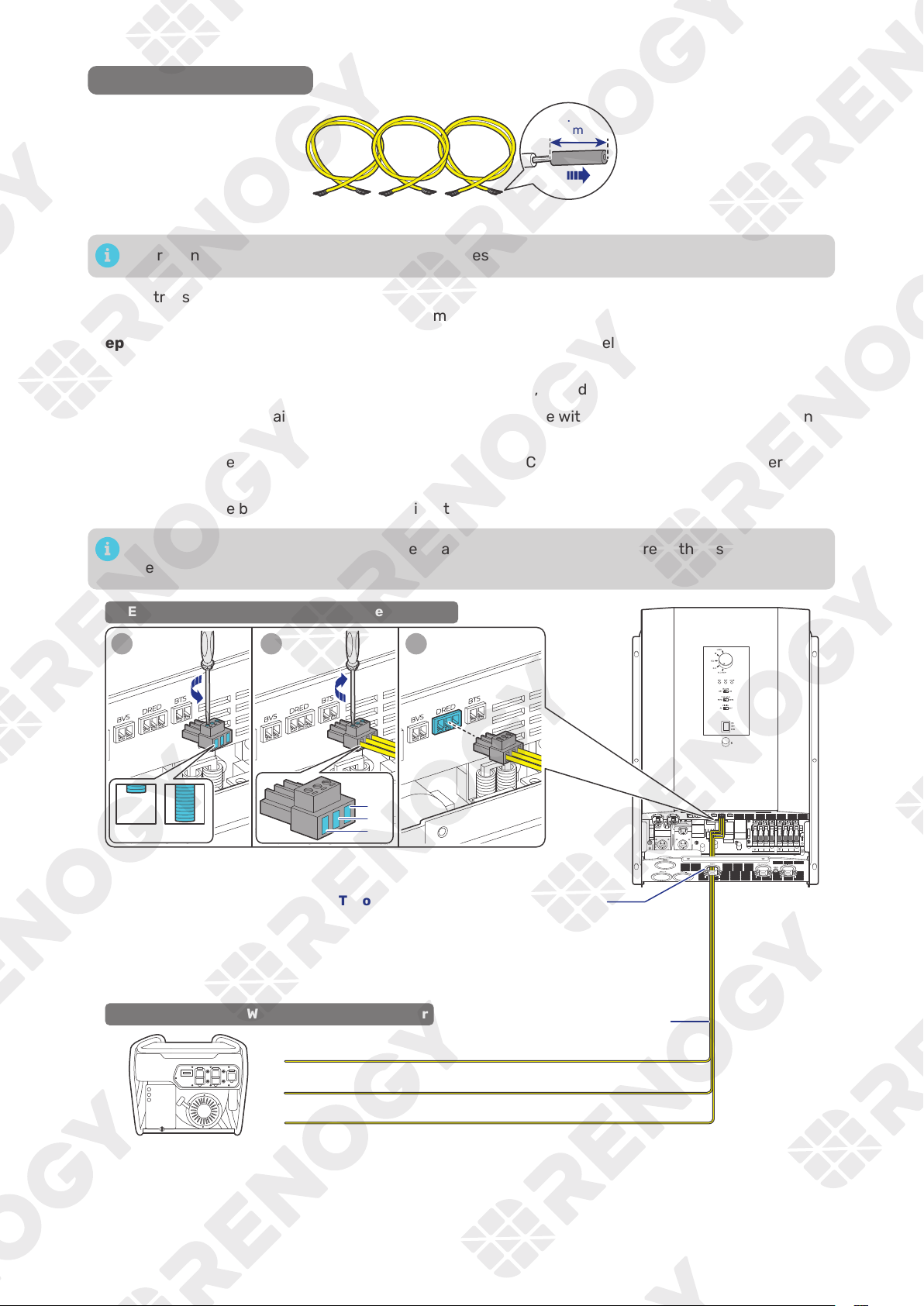
Recommended Accessories
Bare Wires × 3
(8 mm)
0.31 in
There is no polarity requirement for the bare wires.
Step 1: Strip some insulation (0.31 in/8 mm) off each of the three bare wires with a wire stripper, and
run the three bare wires through the grommet of the COM Port on the inverter charger.
Step 2:
Turn the cable retainer screws of NC, C and NO of Dry Contact Relay Connector
counterclockwise with a slotted screwdriver to ensure that the cable retainers are open.
Step 3:
Connect the three bare wires to the corresponding NC, C, and NO wiring holes.
Step 4: Turn the cable retainer screws of NC, C and NO clockwise with a slotted screwdriver to fasten
the cable.
Step 5:
Connect the Dry Contact Relay Connector to the Dry Contact Port (DRED) on the inverter
charger.
Step 6: Connect the bare ends of the three wires to the AC generator.
For details on how to connect the AC Generator to the inverter charger, read the user manual of
the specific generator.
N L2
AC OUT
L1 N L2
AC IN
L1
BAT-
BAT+
AC Generator
1 2 3
Open Close
STEP-2 Install Bare Wires on the AC Generator
C
NC
N0
Through the grommet of the COM Port
NC
C
NO
STEP-1 Install Bare Wires on the Inverter Charger
Bare Wires
— 29 —
4.11. CAN Communication Wiring (Optional)
The REGO 12V 3000W HF Inverter Charger can communicate with other REGO devices and monitoring
devices, enabling safe operation, smart control, remote monitoring, and programmable settings.
You can connect the inverter charger to other REGO devices for real-time inter-device data
communication through any of the CAN1 Port.
The wiring details vary depending on the wiring schemes. This user manual elaborates on inter-device
wiring in two schemes: backbone and daisy chain.
For technical support from Renogy, please contact us through renogy.com/contact-us/.
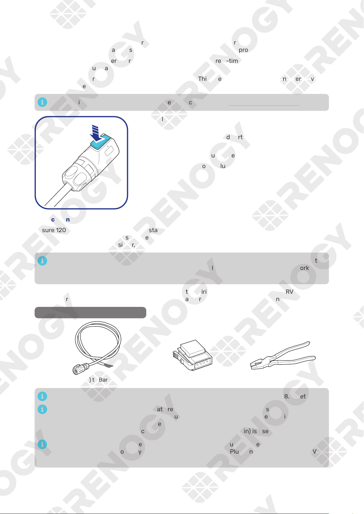
To properly connect or disconnect the LP16 Terminal Plug to or from
the inverter charger, you should
1. Ensure that the plug is oriented vertically toward the CAN1
Communication Port.
2. Press and hold the snap until the process is complete.
Shaking while plugging or unplugging is not allowed.
█
Backbone Network
Ensure 120
Ω
terminating resistors are installed at both ends of the RV-C bus for successful
communication with REGO series devices. If the RV user manual does not determine if the RV-C bus has
a built-in 120
Ω
termination resistor, call the RV manufacturer to confirm.
If the RV-C bus does not have a built-in 120
Ω
termination resistor, the inverter charger will not
communicate properly with other REGO series devices. Please use the Daisy Chain Network for
communication connections.
Connect devices to the inverter charger according to the wiring diagram provided by the RV
manufacturer. Choose proper communication cables according to your specific demands.
Recommended Tools & Accessories
LP16 Plug (7-Pin) to Bare Drop Cable(s) Drop Plugs Split Joint Pliers
The drop cable shall not exceed 19.6 feet (6 m), and the RV-C bus shall not exceed 98.4 feet (30 m).
Choose the appropriate drop plugs that are compatible with the drop sockets used on the
RV-C bus. Different RV manufacturers may use different types of drop sockets for inter-device
communication connections. If you are unsure about the correct drop plug selection, consult with
the RV manufacturer. In this quick guide, the Mini-Clamp II plug (4-pin) is used as an example.
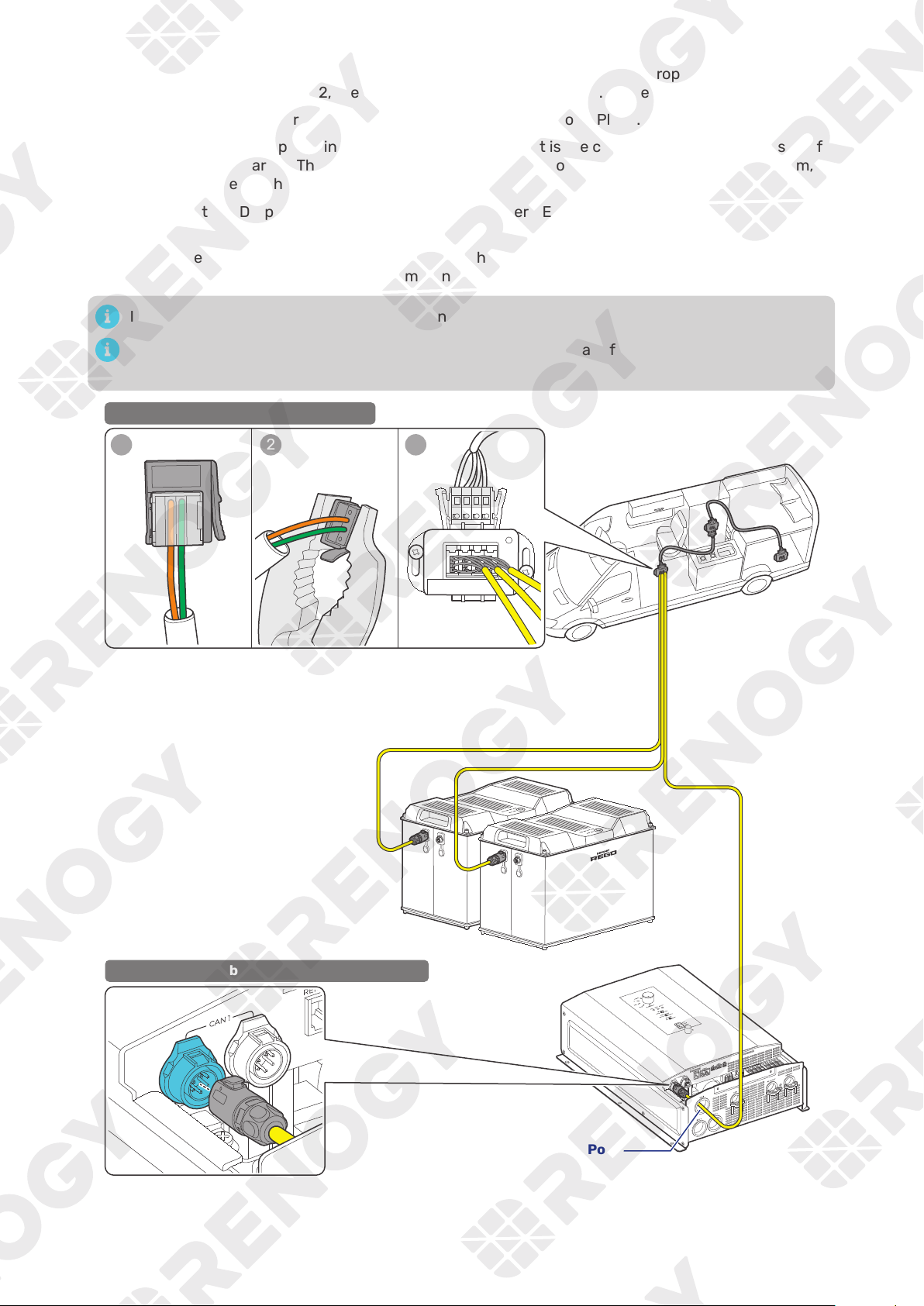
Different Drop Plugs follow different pinouts. Crimp the Drop Plugs on the Drop Cables
following the correct pinout. If you are not sure about the Drop Plug pinout, check with the RV
manufacturer.
— 30 —
Step 1:
Install the Drop Plugs on the bare end of the LP16 Plug (7-Pin) to Bare Drop Cable. The green
CAN_H wire goes to pin 2, the orange CAN_L wire goes to pin 3. Leave pin 1 and pin 4 empty.
Step 2: Squeeze the crimp areas of the Drop Plugs with the Split Joint Pliers.
Step 3: Locate the drop tap (not included) on the RV-C bus that is the closest to the installation site of
the inverter charger. The drop taps are usually located above the entry door, in the bathroom, or
under the bed in the RV.
Step 4:
Connect the Drop Plugs on the drop cables and other REGO devices to the drop sockets on the
drop tap.
Step 5:
Run the LP16 Plug (7-Pin) to Bare Drop Cable through the grommet of the CAN1 Port, and insert
the LP16 Plug to one of the CAN1 Communication Ports.
If you fail to locate the drop taps, please contact the RV manufacturer for help.
Different drop taps are used on the RV-C bus by different RV manufacturers. This user manual
takes the 4-socket drop tap as an example.
1 2 3
4 3 2 1
STEP-1 Install Cables on the RV-C bus
Through the grommet of the CAN1 Port
STEP-2 Install Cables on the Inverter Charger
— 31 —
█
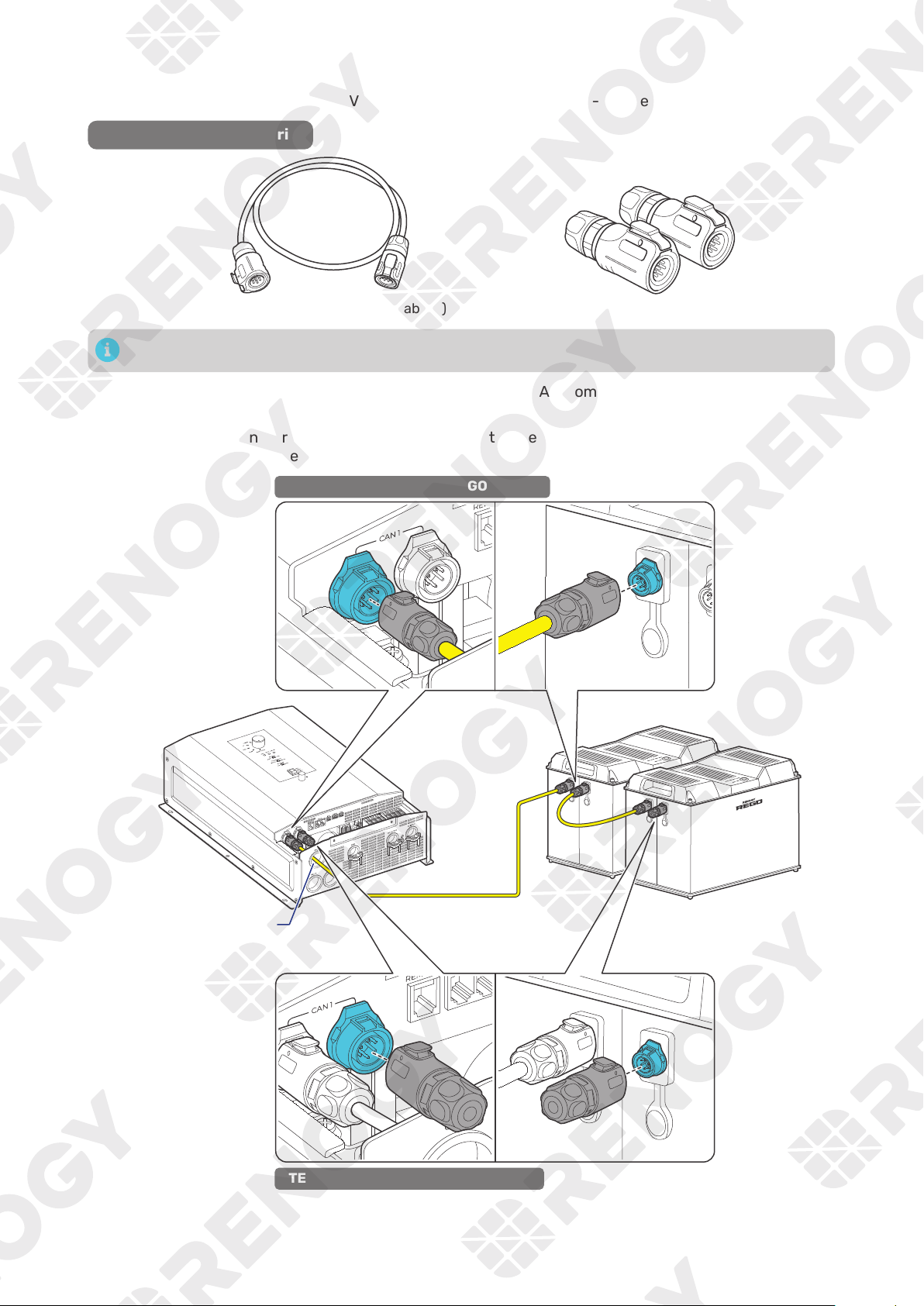
Daisy Chain Network
The daisy chain network applies to RVs that are not integrated with RV-C buses.
Recommended Accessories
LP16 Plug (7-Pin) Communication Cable(s) LP16 Terminator Plugs (7-Pin)
The communication cable should be less than 19.6 feet (6 m).
Step 1: Connect REGO devices in series through either of the CAN Communication Ports with the
Communication Cable(s) (sold separately).
Step 2:
Plug the Terminator Plugs (sold separately) into the free CAN Communication Ports on the first
and last REGO devices.
STEP-1 Install Cables on REGO devices
STEP-2 Install Plugs on REGO devices
Through the grommet
of the CAN1 Port
— 32 —
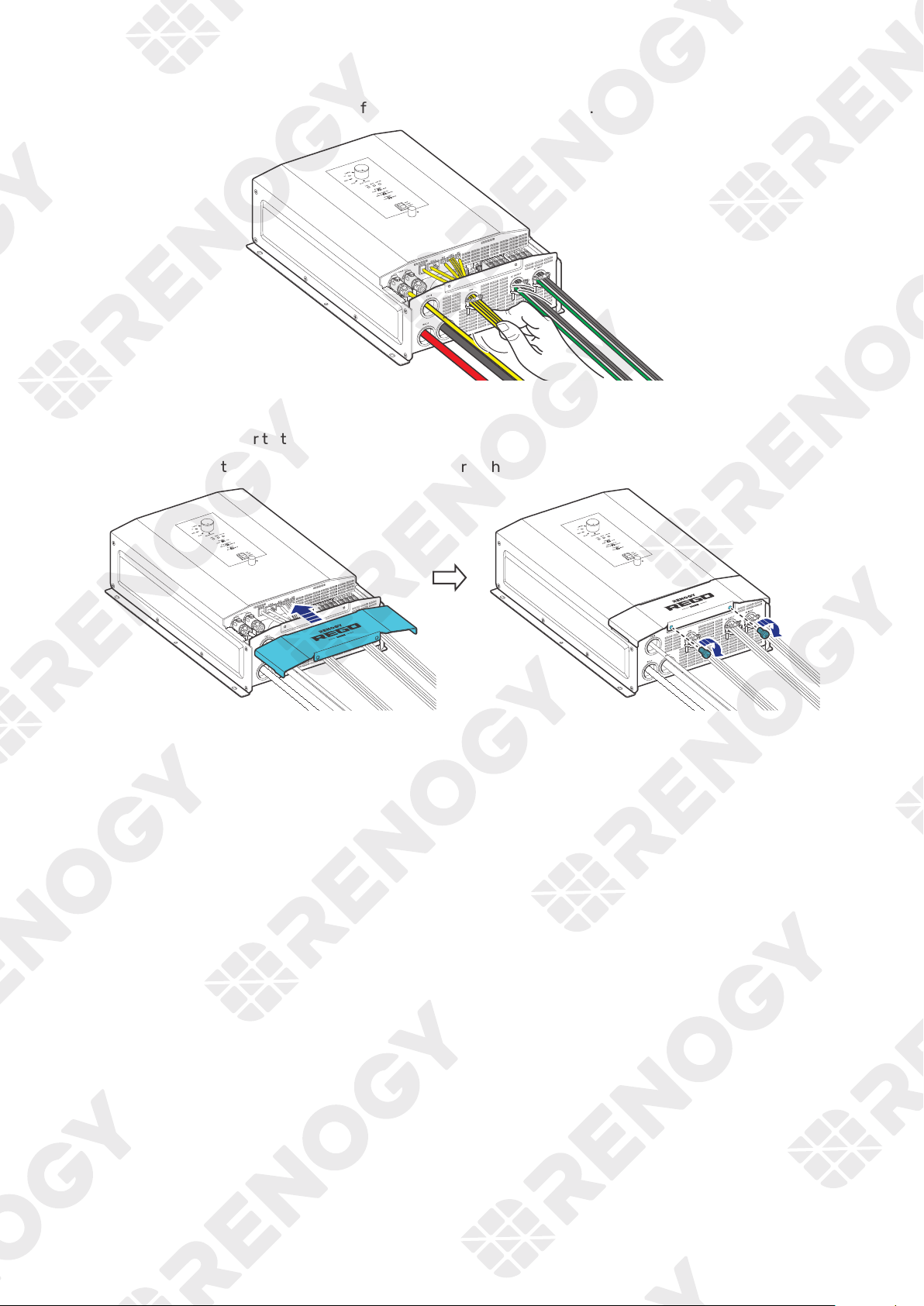
4.12. Inspection
Check and confirm all wires are firmly fastened to the inverter charger.
4.13. Install the Cover
Step 1: Install the cover to the inverter charger.
Step 2: Install the two cover screws clockwise either by hand or by using a Phillips screwdriver.
— 33 —
5. Configuration
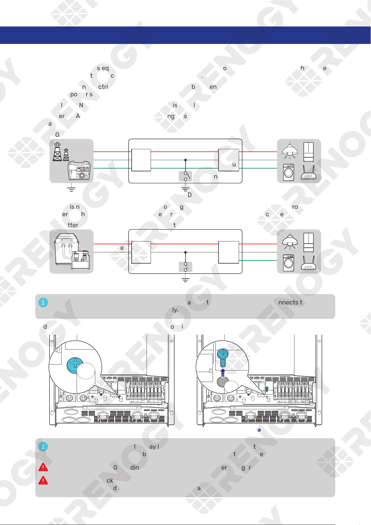
5.1. N-G Bonding Relay
The inverter charger is equipped with a Neutral to Ground (N-G) bonding relay that ensures that either
the neutral in or out contact of the RV is always grounded.
This helps prevent electrical shock caused by contact between the neutral contacts of the RV and
external AC power sources.
By default, the Neutral to Ground bonding relay is enabled when the inverter is shipped from the factory.
When there is AC input current, the N-G bonding relay automatically connects to the grid ground
contact.
Inverter Charger
GND
L
N
PE
L
N
PE
AC
input
AC
output
AC LoadsGrid Power
GND
N-G Bonding
When there is no AC input current, the N-G bonding relay automatically connects to the ground contact
of the inverter charger. In this case, the inverter charger supplies loads with the connected battery.
Inverter Charger
Positive
Negative
L
N
PE
DC
AC
output
Battery
AC Loads
GND
N-G Bonding
In scenarios where the N-G bonding relay is disabled, the N-G bonding relay connects to the
ground contact of the inverter charger only.
To disable the relay function, remove the N-G bonding relay screw.
N L2
AC OUT
L1 N L2
AC IN
L1
BAT-
BAT+
N L2
AC OUT
L1 N L2
AC IN
L1
BAT-
BAT+
Enabled Disable
Enabling the N-G bonding relay may lead to failure of the GFCI connected to the AC loads. In such
case, remove the ground cable between the GFCI and the inverter charger.
In scenarios when N-G bonding relay is disabled, the inverter charger must be grounded.
Risk of electric shock! Ensure the inverter charger is powered off and all connected supplies are
off when enabling or disabling the N-G bonding relay.
— 34 —
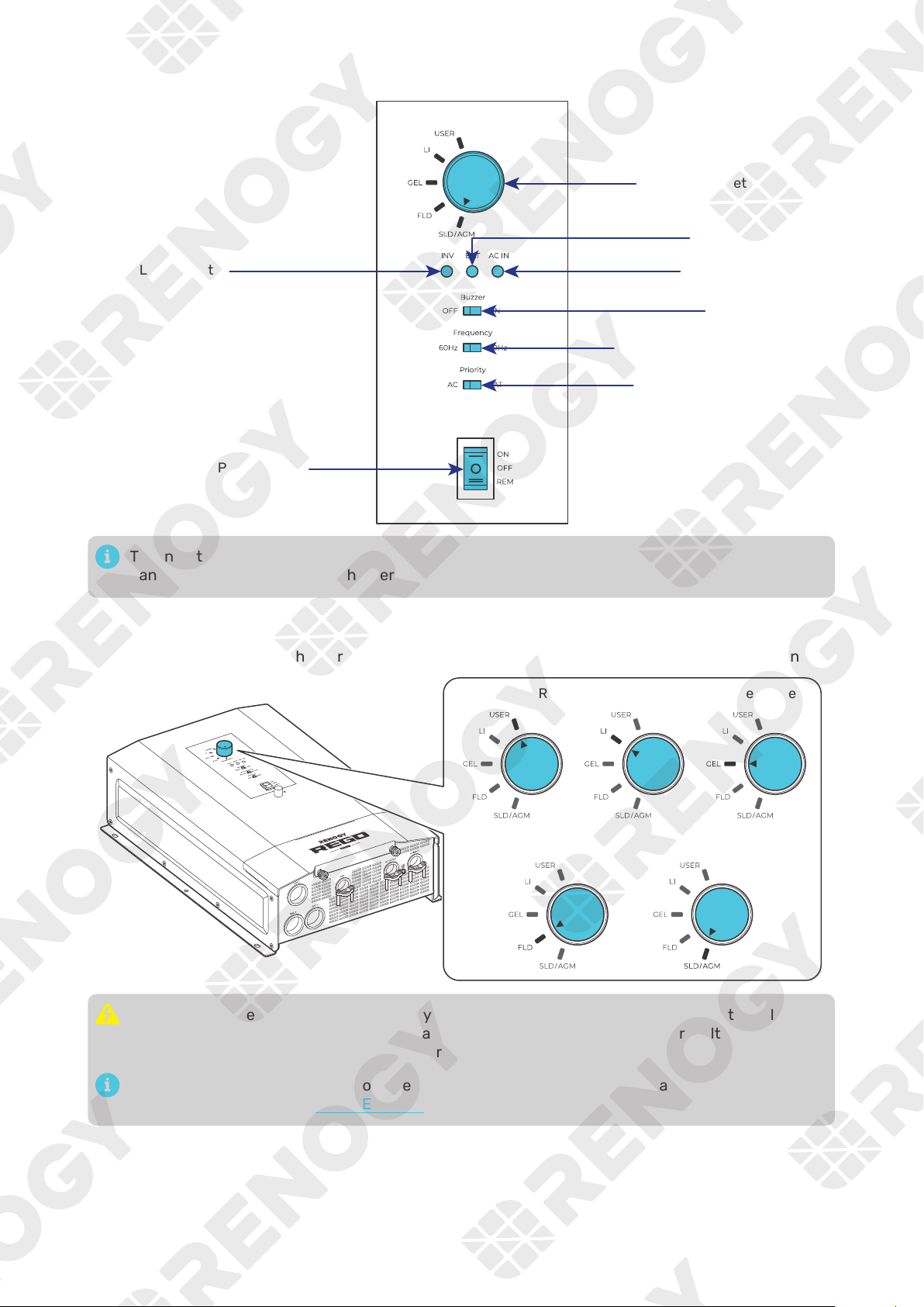
5.2. Configuration Panel
INV LED Indicator
Battery Type Setting Knob
AC IN LED Indicator
BAT LED Indicator
AC Output Priority Setting
AC Output Frequency Setting
Buzzer ON/OFF
The inverter charger generates heat when working. To prevent burns, touch the configuration
panel only when the inverter charger is working.
5.3. Set a Battery Type
Upon installing the inverter charger, set a correct battery type by using the Battery Type Setting Knob.
Lithium Battery
Flooded Battery SLD/AGM Battery
USER Gel Battery
It is essential to ensure that the battery type is configured correctly to avoid any potential
damage to the inverter charger because any damage to the inverter charger resulting from an
incorrect battery type setting voids the warranty.
After entering the USER mode, you need to use the DC Home app to program the battery
parameters. Refer to the “5.4 USER Mode” for details.
— 35 —
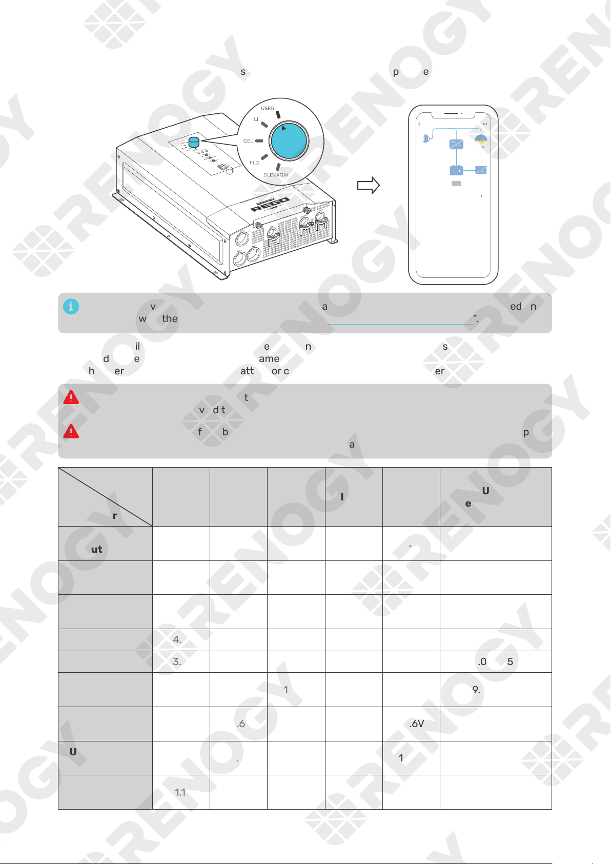
5.4. USER Mode
Setting the battery type to USER allows you to customize your battery parameters. You can modify the
parameters in the DC Home app.
RIV1230RCH-SPS
Shore Power
Load
Battery
Battery Output Setting Available
Output Current
10
A
Output Voltage
4.5
V
lnput Frequency
120
Hz
Input Voltage
120
V
Line Charging Current
10
A
60
Hz
Load Power
Output Frequency
12
V
Battery Voltage
200
W
Boost
Setting the inverter charger to USER Mode is available when the inverter charger is powered on
and paired with the DC Home app. For details, see “7. Monitor the Inverter Charger”.
The table below illustrates the default and recommended parameters for batteries that can be
connected to the inverter charger. The parameters may vary depending on the specific battery you use.
Read the user manual of the specific battery or contact the battery manufacturer for help if necessary.
Before modifying battery parameters, check the table below first. Incorrect parameter setting will
damage the device and void the warranty.
Read the user manual of the battery when customizing a preset battery. Incorrect battery type
selection damages the inverter charger and voids the warranty.
Battery
Type
Parameters
SLD/AGM GEL FLOODED LI (LFP)
USER
(Default)
USER
(Recommended)
Overvoltage
Shutdowm
15.8V 15.8V 15.8V 15.8V 15.8V 9.0—16.0V
Overvoltage
Limt
15.5V 15.5V 15.5V 14.8V 15.5V 9.0—16.0V
Equalization
Volatge
— — 14.8V — 14.8V 9.0—15.5V
Boost Voltage
14.6V 14.2V 14.6V 14.4V 14.2V 9.0—15.5V
Float Voltage
13.8V 13.8V 13.8V — 13.8V 9.0—15.5V
Boost Return
Voltage
13.2V 13.2V 13.2V 13.6V 13.2V 9.0—15.5V
Low Voltage
Reconnect
12.6V 12.6V 12.6V 12.8V 12.6V 9.0—16.0V
Under Voltage
Warning
12.0V 12.0V 12.0V 12.0V 12.0V 9.0—15.5V
Low Voltage
Shutdown
11.1V 11.1V 11.1V 11.5V 11.1V 9.0—15.5V
— 36 —
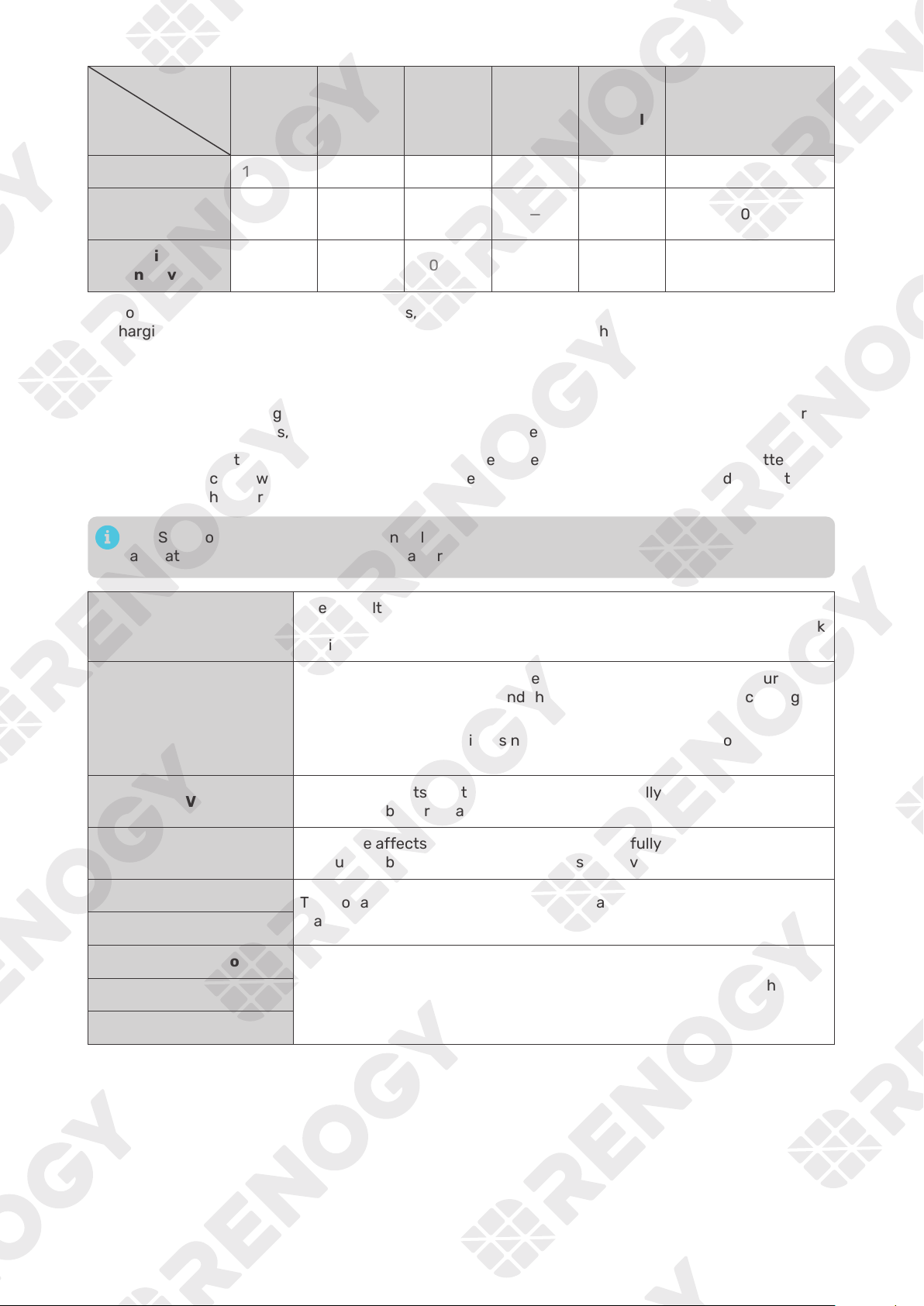
Battery
Type
Parameters
SLD/AGM GEL FLOODED LI (LFP)
USER
(Default)
USER
(Recommended)
Boost Duration
120 min* 120 min* 120 min* — 120 min* 10—600 min
Equalization
Duration
— — 120 min — 120 min 0—600 min
Equalization
Interval
0 day** 0 day** 30 days — 30 days 0—255 days
z
*For SLD/AGM, GEL, and Flooded batteries, the inverter charger automatically switches to float
charging when the charging current drops below the tail current of the battery for 30 seconds.
z
**No equalized charging.
z
Parameters in grey cannot be configured manually.
z
When the battery voltage reaches the Low Voltage Shutdown value, the BAT LED is solid yellow or
red. Disconnect all loads, and charge the battery immediately.
Before modifying battery parameters in USER mode, check the table below and consult the battery
manufacturer to check whether modification is allowed. Incorrect parameter setting will damage the
device and void the warranty.
In USER mode, when the Equalization Voltage matches the Boost Voltage and Float Voltage, the
activation mechanism for the lithium battery is initiated.
Overvoltage Shutdown
The default protection voltage is 15.8V. Improper setting may affect the
safety of the battery. Please consult the battery manufacturer and check
if this voltage value needs to be reset.
Equalization Voltage
1. For lead-acid batteries, please consult your battery manufacturer to
obtain the voltage value and then complete the settings according to
the feedback.
2. If equalization charging is not required, set the voltage to boost
voltage.
Boost Voltage
This value affects whether the battery can be fully charged. Please
consult the battery manufacturer and set the value properly.
Float Voltage
This value affects whether the battery can be fully charged. Please
consult the battery manufacturer and set the value properly.
Under Voltage Warning
This voltage value affects the life of the battery. Consult the battery
manufacturer and check if this voltage value needs to be set.
Low Voltage Shutdown
Boost Duration
Please consult the battery manufacturer if it is necessary to set this
parameter value.
Equalization Duration
Equalization Interval
— 37 —
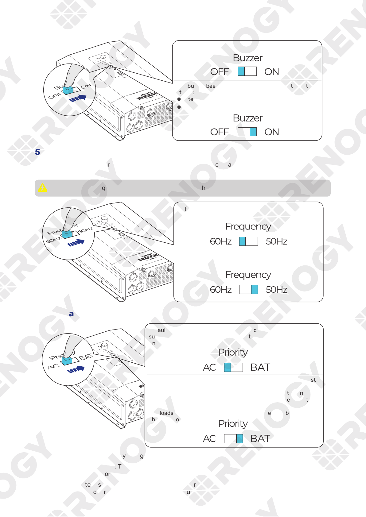
5.5. Enable/Disable the Buzzer
5.6. Set an AC Output Frequency
Configure the AC output frequency of the inverter charger in accordance with the frequency of the
connected AC loads.
The AC output frequency should be consistent with the input source frequency.
Default: 60 Hz
Option 2: 50 Hz
5.7. Set an AC Output Priority
supplied by the grid and then by the battery when the grid power is
unavailable.
supplied by the battery.
When the battery voltage drops below low voltage shutdown
(±0.3V), the grid charges the battery and supplies the connected
loads.
The loads are again supplied by the battery when the battery
charging completes.
How to check whether a battery charging process completes?
z
For non-lithium batteries: The battery charging is considered complete when the battery stays in the
float charging stage for 2 hours.
z
For lithium batteries: The battery charging is considered complete when the battery stays in the
constant voltage charging stage with a charging current less than the battery tail current for 2
hours.
— 38 —
6. Power On/Off and LED Indicators
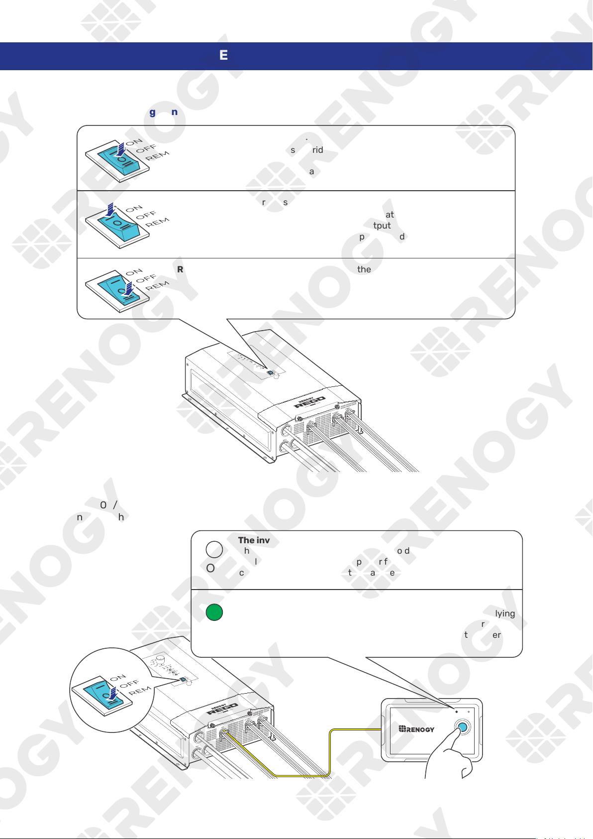
6.1. Power On/Off
█
Method 1: Through On/Off/Remote Power Switch
OFF:
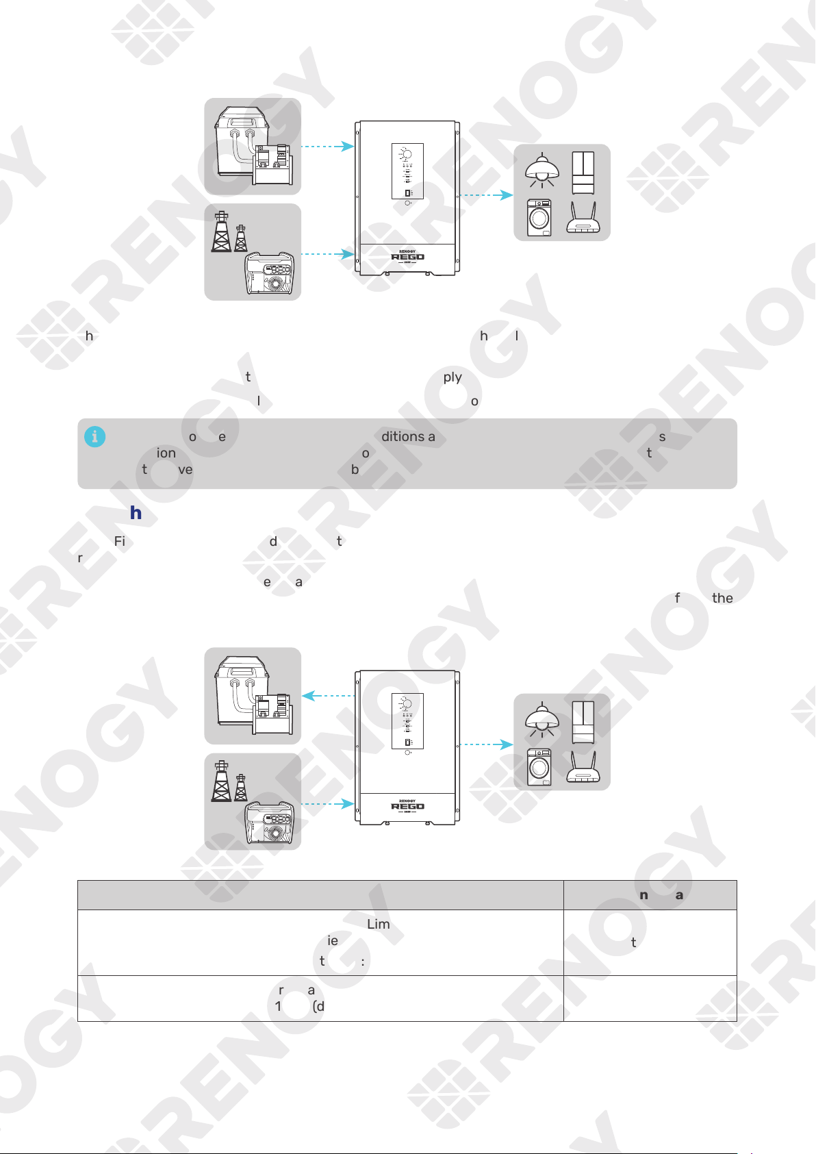
ON:
The inverter charger uses grid power to directly power AC loads or
The inverter charger prioritizes charging the batteries or supplying power to
grid and batteries can work together to power loads up to a combined load
REM:
█
Method 2: Through Wired Remote Control
Push the On/Off/Remote Power Switch to the REM position. Press the RMS-P button to power on or off
the inverter charger.
ON ERR
RMS-P2
The inverter charger is o.
The inverter charger uses grid power to directly power AC loads or
appliances without drawing power from the batteries. The grid
charges the connected battery at the same time.
The inverter charger is on.
The inverter charger prioritizes charging the batteries or supplying
power to the loads from the grid based on the AC Output Priority.
In this mode, the grid and batteries can work together to power
loads up to a combined load of 6000W.
ON
ON
— 39 —
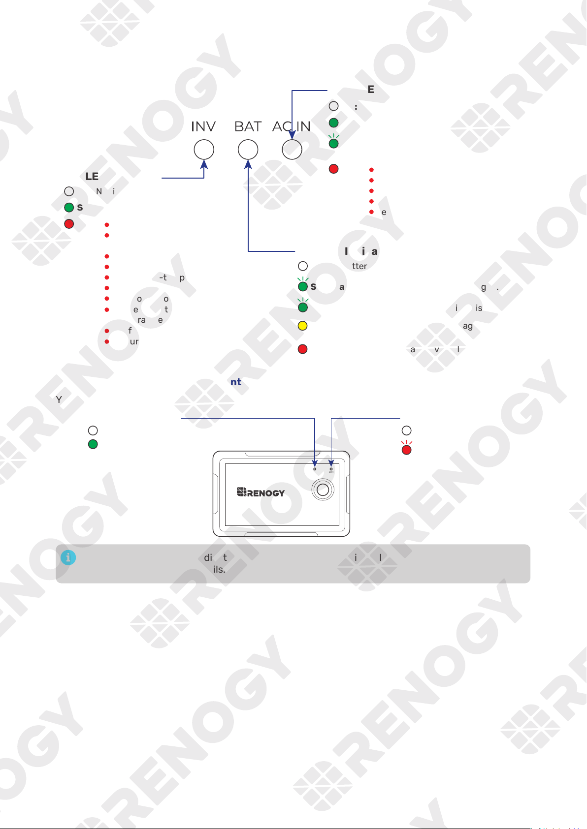
6.2. LED Indicators
█
Indicator of the Inverter Charger
O: No AC input detected
AC IN LED Indicator
INV LED Indicator
Solid:
Solid:
Solid:
O:
BAT LED Indicator
O: No battery detected
Not in inverter mode
The output voltage is normal
Solid:
Flash:
Slow flash (2s): The battery is being charged.
Fast flash (0.5s):
Solid: The grid voltage is normal
The grid is supplying the loads
and/or charging the battery.
Voltage error on AC IN L1
Voltage error on AC IN L2
Grid current error
Input frequency error
Reverse AC input and output
The battery is being discharged.
Battery undervoltage/overvoltage
warning
Battery undervoltage/overvoltage
error
Solid:
Inverter overcurrent protection
Inverter output voltage
protection
Inverter over-temperature
Internal over-temperature
DC-DC over-temperature
DC protection
Transformer over-temperature
Low temperature/Internal
temperature sensor error
Fan failure
AC current protection
█
Indicator of the Wired Remote Control
You can also check the operating status of the inverter charger on the Wired Remote Control.
ON ERR
RMS-P2
O: No fault
Flash: System fault
O:
On:
ERR LED Indicator
ON LED Indicator
A solid yellow or red LED indicates that the inverter charger is faulty. Please login to the DC Home
app for troubleshooting details.
— 40 —
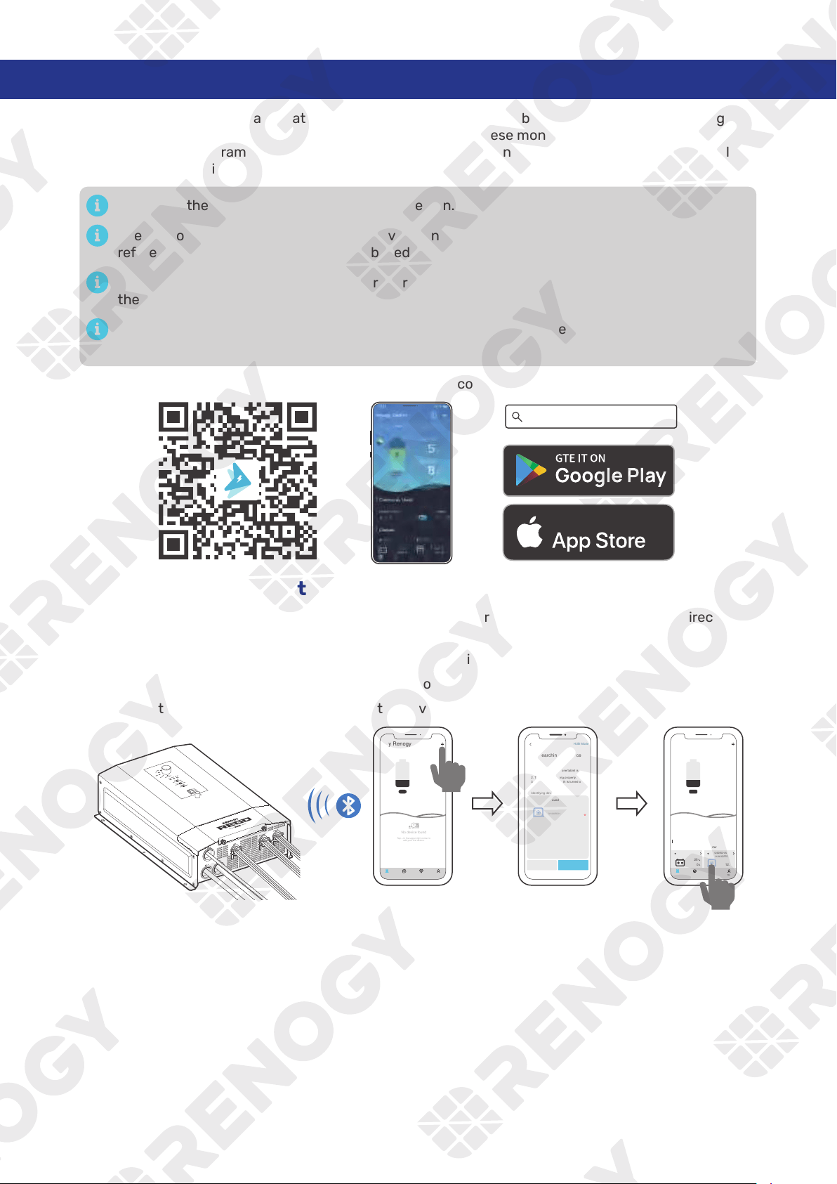
7. Monitor the Inverter Charger
Depending on the specific application, the inverter charger can establish either short-range or long-
range communication connections with monitoring devices. These monitoring devices facilitate real-
time monitoring, programming, and complete system management, offering comprehensive control
and enhanced flexibility.
Make sure the Bluetooth of your phone is turned on.
The version of the DC Home app might have been updated. Illustrations in the user manual are for
reference only. Follow the instructions based on the current app version.
Make sure that the inverter charger is properly installed and powered on before it is paired with
the DC Home app.
To ensure optimal system performance, keep the phone within 10 feet (3 m) of the inverter
charger.
Download the DC Home app. Login to the app with your account.
DC Home App
Download on the
7.1. Short-Range Monitoring via DC Home App
If only short-range monitoring is required, connect the inverter charger to the DC Home app directly
through the Bluetooth of your phone.
Step 1:
Open the DC Home app. Tap + to search for new devices.
Step 2:
Tap Confirm to add the newly found device to the device list.
Step 3:
Tap the inverter charger icon to enter the device information interface.
My Renogy
25%
A
Device
Device
Battery
RBT12400LFPL-...
Inverter
Scene Community Me
RIV1230RCH-SPS
BT-TH-161CFF52
%
25
A
0 12.0 V
W
0
Cancel Confirm
RIV1230RCH-SPS
Inverter Charger
Found Devices
HUB Mode
Searching for device
Please make sure:
1. Bluetooth on this phone/tablet is
turned on.
2. The device is running properly.
3. The device's Bluetooth is turned on.
Identifying device...
No device found
Tap + in the upper-right corner to
add your first device.
---
My Renogy
Time remaining
--
CommunityDevice Select Me
— 41 —
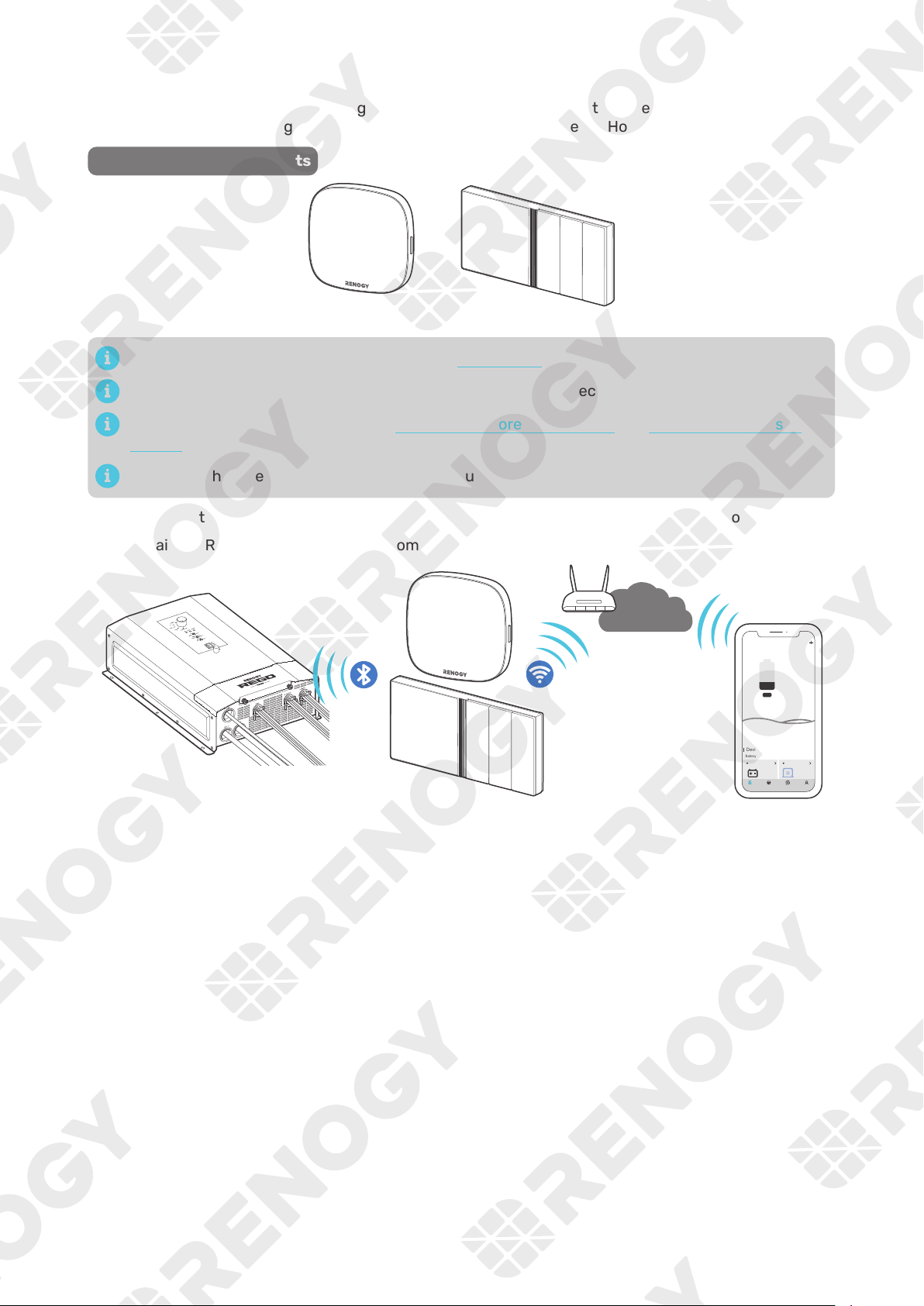
7.2. Wireless Long-Range Monitoring
If long-range communication and programming are required, connect the inverter charger to Renogy
ONE (sold separately) through Bluetooth, and the Renogy ONE to the DC Home app through Wi-Fi.
Recommended Components
*RENOGY ONE Core or Renogy ONE M1
Components marked with “*” are available on renogy.com.
Make sure that the Renogy ONE is powered on before the connection.
For instructions on Renogy ONE, see Renogy ONE Core User Manual and Renogy ONE M1 User
Manual.
Make sure the inverter charger does not communicate with any other device.
Step 1: Connect the inverter charger to the Renogy ONE through the Bluetooth of your phone.
Step 2: Pair the Renogy ONE with the DC Home app through Wi-Fi.
My Renogy
25%
A
Device
Devices
Battery
RBT12400LFPL-...
Controller
Scene Community Me
RIV1230RCH-SPS
%
25
A
0 12
W
V
0
Internet
— 42 —
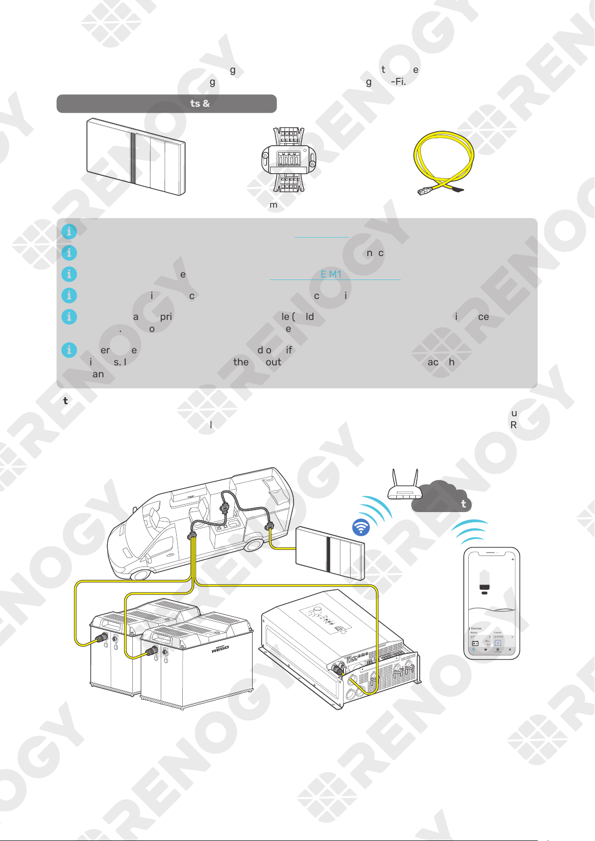
7.3. Wired Long-Range Monitoring (Backbone Network)
If long-range communication and programming are required, connect the inverter charger to Renogy
ONE through wires, and the Renogy ONE to the DC Home app through Wi-Fi.
Recommended Components & Accessories
RJ45 Plug to Bare Drop CableCommon Drop Tap*Renogy ONE M1
Components marked with “*” are available on renogy.com.
Make sure that the Renogy ONE is powered on before the connection.
For instructions on Renogy ONE M1, see Renogy ONE M1 User Manual.
Make sure the inverter charger does not communicate with any other device.
Select the appropriate communication cable (sold separately) according to the distance between
devices. The communication cable should be less than 19.6 feet (6 m).
Different terminal block plugs are used on different Common Drop Taps and follow different
pinouts. If you are unsure about the pinout of the terminal block plug, contact the RV
manufacturer.
Step 1:
Replace the terminated drop tap at either end of the RV-C bus with the Common Drop Tap (not
included). Secure the bare wires of the Drop Cable (not included) onto the terminal block plug of
the Common Drop Tap following the terminal block plug pinout. Plug the Drop Cable to the RJ45
port of Renogy ONE.
Step 2:
Monitor and program the complete system on Renogy ONE or the DC Home app.
My Renogy
25%
A
Device
Devices
Battery
RBT12400LFPL-...
Controller
Scene Community Me
RIV1230RCH-SPS
%
25
A
0 12
W
V
0
Internet
— 43 —
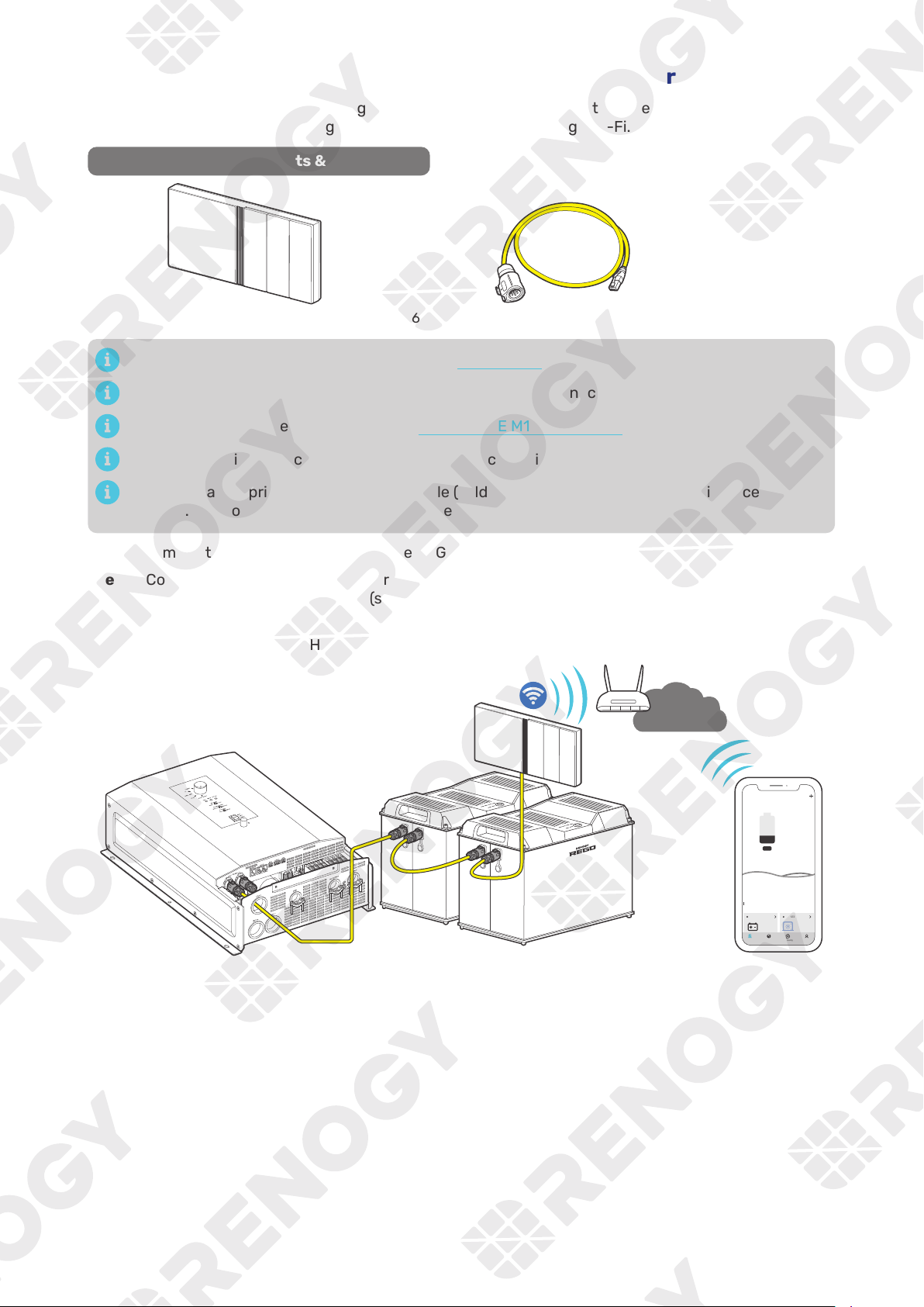
7.4. Wired Long-Range Monitoring (Daisy Chain Network)
If long-range communication and programming are required, connect the inverter charger to Renogy
ONE through wires, and the Renogy ONE to the DC Home app through Wi-Fi.
Recommended Components & Accessories
LP16 Plug (7-Pin) to RJ45 Communication Adapter Cable
*Renogy ONE M1
Components marked with “*” are available on renogy.com.
Make sure that the Renogy ONE is powered on before the connection.
For instructions on Renogy ONE M1, see Renogy ONE M1 User Manual.
Make sure the inverter charger does not communicate with any other device.
Select the appropriate communication cable (sold separately) according to the distance between
devices. The communication cable should be less than 19.6 feet (6 m).
Step 1:
Remove the Terminator Plug from the REGO device at either end of the daisy chain.
Step 2: Connect the Renogy ONE to the free CAN Communication Port on the REGO device with the
Communication Adapter Cable (sold separately).
Step 3:
Pair Renogy ONE with the DC Home app. Monitor and program the complete system on the
Renogy ONE or the DC Home app.
My Renogy
25%
A
Device
Devices
Battery
RBT12400LFPL-...
Controller
Scene Community Me
RIV1230RCH-SPS
%
25
A
0 12
W
V
0
Internet
— 44 —
8. Working Logic
REGO 12V 3000W HF Inverter Charger combines an inverter charger with an automatic transfer switch
into one complete system.
Featuring a three-stage battery charging mode when connected to the AC grid input, the inverter
charger is capable of producing cleaner, smoother, and more reliable electricity to address your diverse
needs.
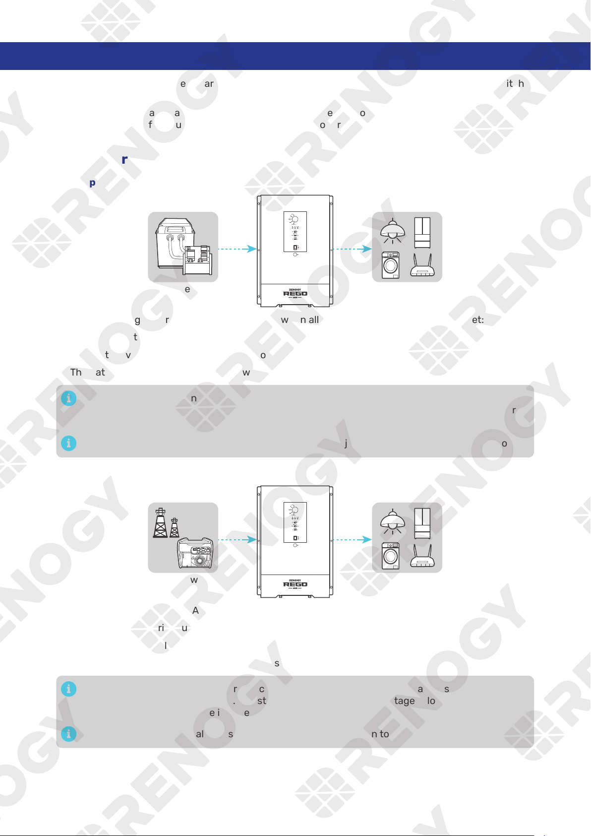
8.1. Power Supply Logic
█
Supply by Battery First
Battery AC Loads
The inverter charger works in Battery First mode when all of the following conditions are met:
z
The AC Output Priority button is toggled to BAT.
z
The battery voltage is no lower than the Low Voltage Shutdown value.
z
The battery current is sufficient to power the connected loads.
When none of the designated working conditions are met, the inverter charger seamlessly
transitions to AC First mode. In instances where grid power is unavailable, the inverter charger
ceases its operation.
If the battery fails to supply all loads, the grid seamlessly joins in to provide the necessary power.
█
Supply by AC First
Grid Power AC Loads
The inverter charger works in AC First mode when all of the following conditions are met:
z
The AC Output Priority button is toggled to AC.
z
Grid power is available.
z
The grid power is sufficient to supply all loads.
When none of the designated working conditions are met, the inverter charger seamlessly
transitions to Battery First mode. In instances where the battery voltage is lower than the Low
Voltage Shutdown value, the inverter charger ceases its operation.
If the grid fails to supply all loads, the battery seamlessly joins in to provide the necessary power.
— 45 —
█
Supply by Both Battery and AC
Grid Power
AC Loads
Battery
The inverter charger uses both battery and grid as the supply when all of the following conditions are
met:
z
Neither the battery nor the grid can independently supply all loads.
z
The battery voltage is no lower than the Low Voltage Shutdown value.
When none of the designated working conditions are met, the inverter charger seamlessly
transitions to AC First mode. Powering off some loads to ensure the grid can supply the rest loads
and the inverter charger charges the battery.
8.2. Charging Logic
In AC First mode where the grid power is the only supply source, the inverter charger automatically
recognizes the battery voltage and charges the battery.
By default, the inverter charger charges the battery at 150A. You can customize the charging current to
a value between 5A and 150A on the DC Home app. For the recommended charging current, refer to the
user manual of the specific battery.
Grid Power
AC Loads
Battery
Battery Voltage Charging Status
Drops to the Overvoltage Limt value:
z
For lithium batteries: 14.8V (default)
z
For non-lithium batteries: 15.5V (default)
Start charging
Rises to Overvoltage Shutdown value:
15.8V (default)
Stop charging
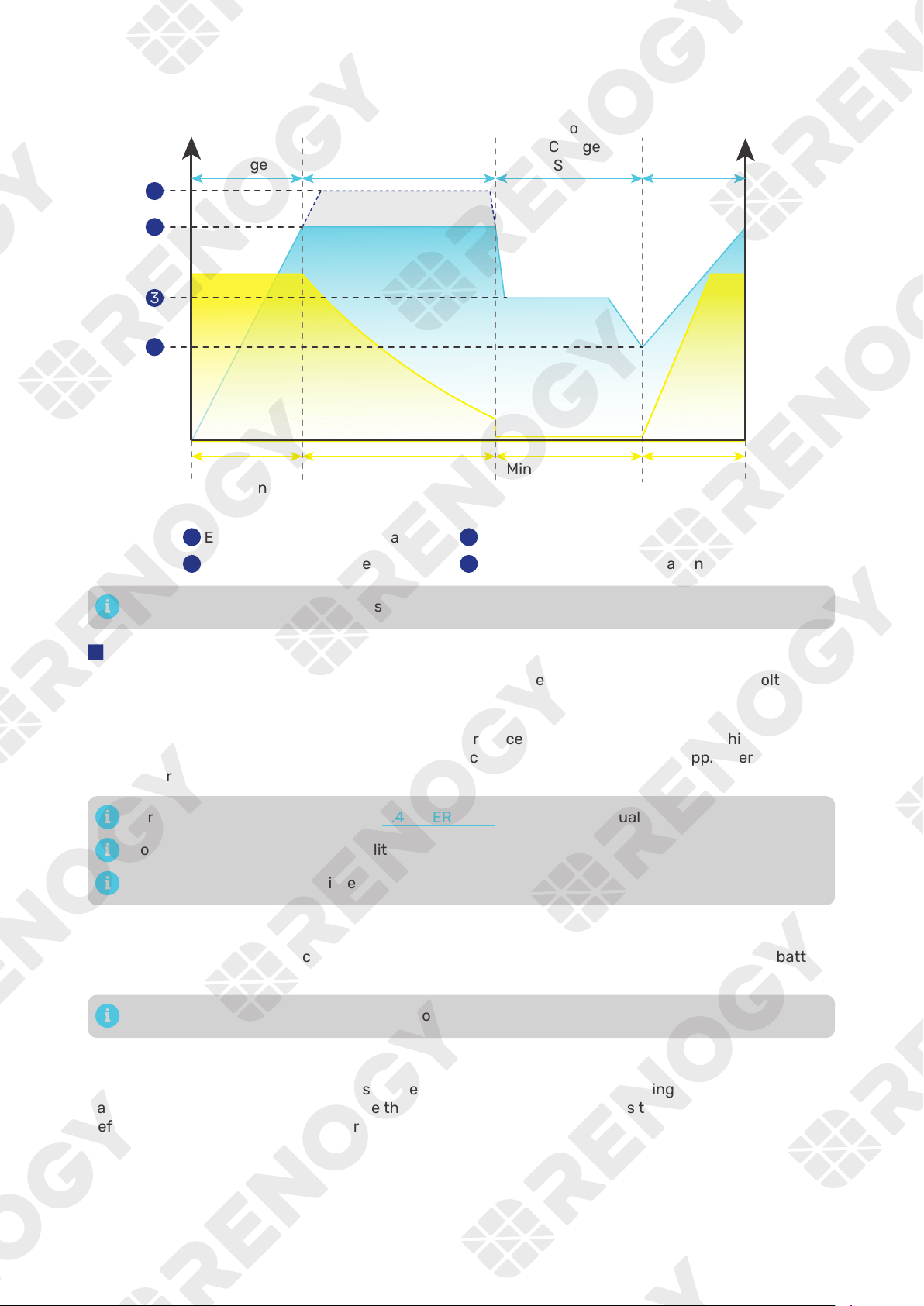
— 46 —
8.3. Battery Charging Stages
U/V
Current
Voltage
I/A
Bulk
Charge
Stage
Reset to
Bulk
Charge
Stage
Boost Charge Stage
(Constant Voltage)
Float
Charge
Stage
Maximum
Current
Reduce Current Minimum Current Increase to
Maximum
Current
Equalization charging voltage
Boost charging voltage
Equalization
1
2
Float charging voltage
Low voltage reconnect charging voltage
3
4
1
2
3
4
Adjust the time depending on the specific battery bank size.
█
Bulk Charge Stage
The inverter charger will supply constant current until the battery voltage reaches the boost voltage.
█
Boost Charge Stage
The inverter charger will supply constant voltage and reduce the current slowly through this stage. By
default, the Boost Duration is set to 2 hours. You can customize it on the DC Home app. After this time
the charger will enter the float stage.
For details on Boost Duration, see “5.4. USER Mode” in this user manual.
Boost Duration is not required for lithium batteries.
The stage is determined by internal software in the inverter charger.
█
Float Charge Stage
During this stage the inverter charger will supply a constant voltage which is determined by the battery
selected and will keep current at a minimum level. This stage acts as a trickle charger.
The float charge stage is not applicable to lithium batteries.
█
Equalization
This stage is only available for batteries with equalization, such as flooded. During this stage the
batteries are charged at a higher voltage than normal and for most batteries this could cause damage.
Refer to the user manual of the battery or contact the battery manufacturer to see if this stage is
needed.
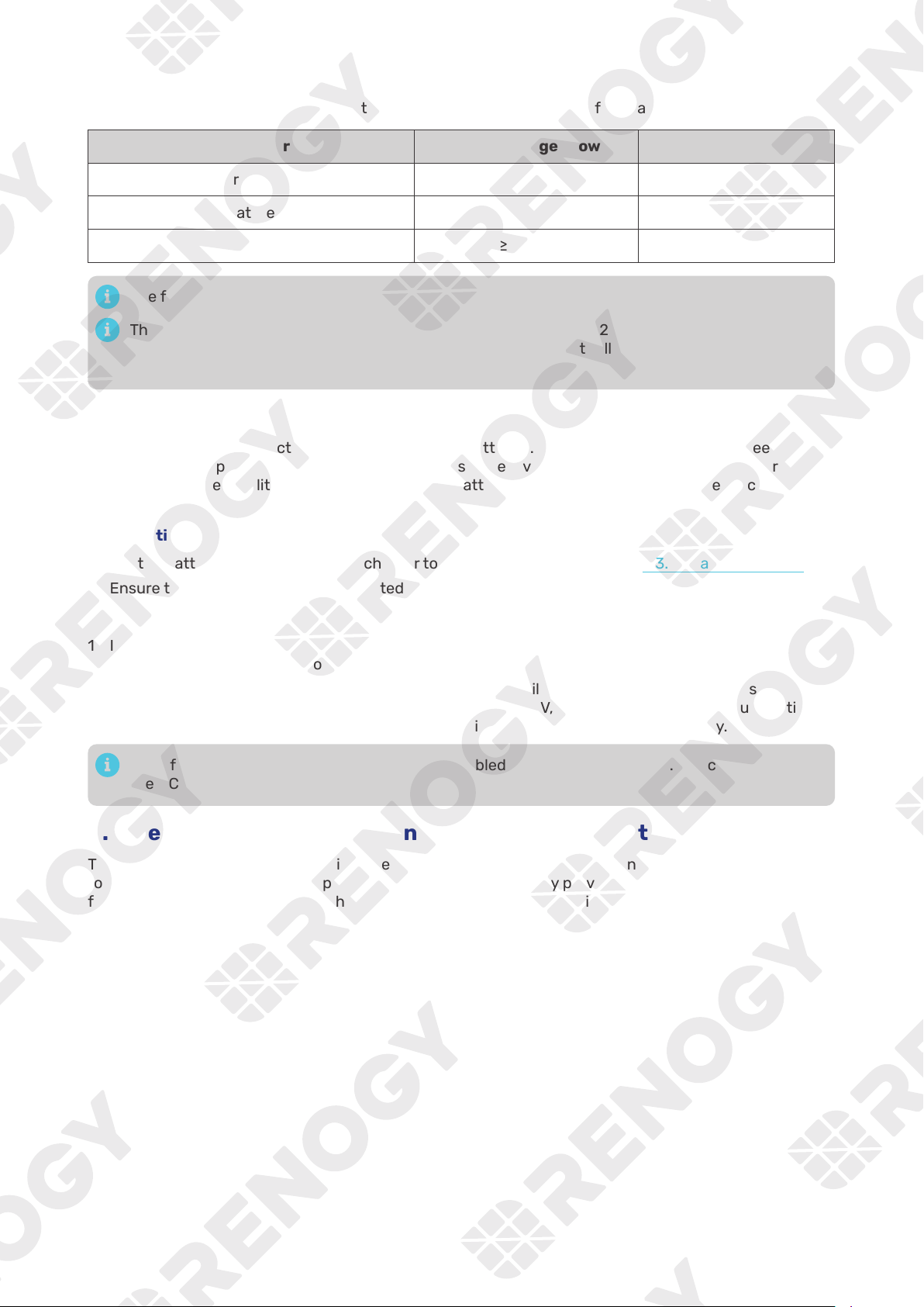
— 47 —
8.4. Heat Dissipation Logic
The inverter charger uses fans for heat dissipation. The working logic of the fans is as follows:
Inverter Charger Inverter Charger Power Fan
— ON
— ON
— ON
The fans start working when any of the above condition is met.
The inverter charger fans start working when the output reaches 200W or higher, with the fan
speed increasing as the output power rises. The fans operate at full speed when the output power
reaches 2700W.
8.5. Activation Logic for Lithium Battery
The inverter charger can activate connected lithium batteries. Lithium batteries may enter sleep mode
when the in-built protection is triggered. In such case, the inverter charger provides a small current to
reactivate the sleeping lithium battery. The lithium battery can be charged normally after successful
activation.
█
Operation Conditions
1. Set the battery type of the inverter charger to LI or USER. For details, see “5.3. Set a Battery Type”.
2. Ensure the inverter charger is connected to the grid and the grid power is accessible.
█
Operation Logic
1. In lithium battery mode, the inverter charger automatically enables the activation function and
provides a constant voltage of over 14.0V to 14.4V to activate the lithium battery.
2. After activation for 1 minute, the inverter charger temporarily stops activation and detects the
battery voltage again. If the battery voltage is no less than 9V, the inverter charger will automatically
turn off the activation mode. Otherwise, it will continue to activate the lithium battery.
By default, the lithium activation function is enabled in the inverter charger. You can disable it in
the DC Home app.
8.6. Heating Module Activation Logic for Lithium Battery
The inverter charger is equipped with a heating module that enables the connected lithium battery
to function normally even at temperatures as low as 32°F (0°C) by providing heat to the battery. This
feature ensures that the inverter charger can operate smoothly even in extremely cold conditions down
to -4°F (-20°C).
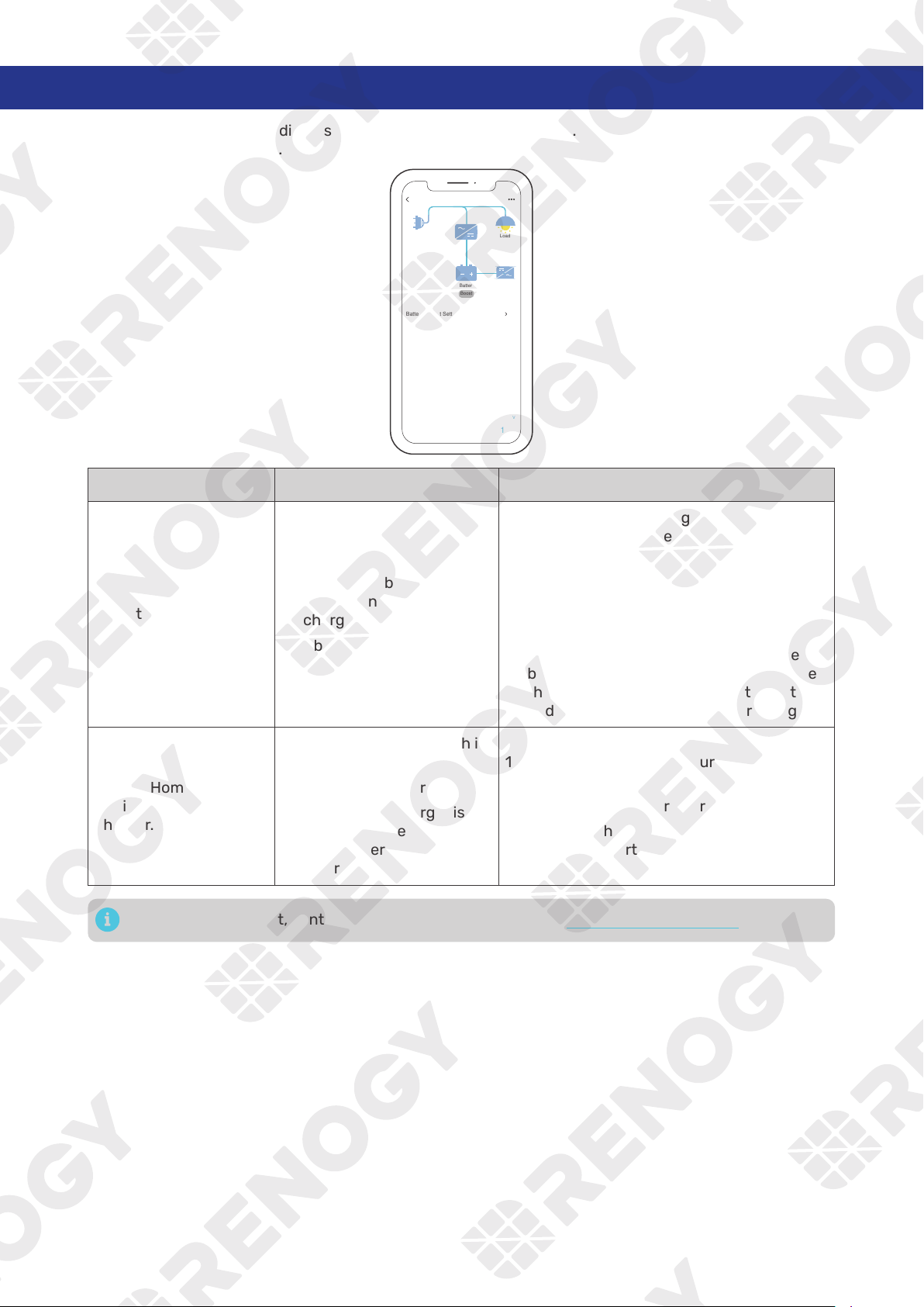
— 48 —
9. Troubleshooting
A solid yellow or red LED indicates that the inverter charger is faulty. Please login to the DC Home app
for troubleshooting details.
RIV1230RCH-SPS
Shore Power
Load
Battery
Battery Output Setting Available
Output Current
10
A
Output Voltage
4.5
V
lnput Frequency
120
Hz
Input Voltage
1000
V
Line Charging Current
10
A
60
Hz
Load Power
Output Frequency
12
V
Battery Voltage
200
W
Boost
Problem Possible Causes Solution
No battery is detected.
1. The cables between the
battery and the inverter
charger are loose.
2. Abnormal battery voltage
1. Check the cable wiring between the
battery and the inverter charger, and
ensure the cables are correctly and firmly
installed.
2. Measure the battery voltage with a
multimeter. A normal battery voltage
should range from 11V to 15.8V. The
inverter charger may fail to detect the
battery when the battery voltage is lower
than 11V. In such case, charge the battery,
and reconnect it to the inverter charger.
The DC Home app fails
to discover the inverter
charger.
1. Your phone’s Bluetooth is
off.
2. The inverter charger is off.
3. The inverter charger is far
away from the phone of
tablet where the DC Home
app runs.
1. Turn on Bluetooth on your phone or
tablet.
2. Turn on the inverter charger.
3. Keep the phone or tablet within 10 feet (3
m) of the inverter charger.
For technical support, contact our technical service through renogy.com/contact-us.
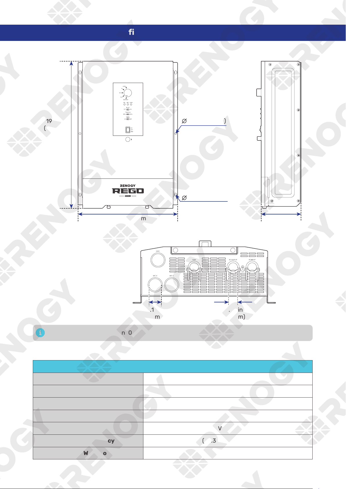
— 49 —
10. Dimensions & Specifications
10.1. Dimensions
19.37 in
(492 mm)
13.11 in (333 mm)
1.18 in
(30 mm)
0.79 in
(20 mm)
5.31 in
(135 mm)
0.28 in (7 mm)
0.28 in (7 mm)
Dimension tolerance: ±0.2 in (0.5 mm)
10.2. Technical Specifications
Inverter Specifications
Rated Output Power 3000W @113°F (45°C)
Surge Power (100 ms) 9000VA
Surge Power (5 seconds) 4500VA
Surge Power (10 seconds) 3600W
Nominal Output Voltage RMS 120V AC (±3%)
Output Frequency 50Hz (±0.3Hz) / 60Hz (±0.3Hz)
Output Wave Form Pure Sine Wave
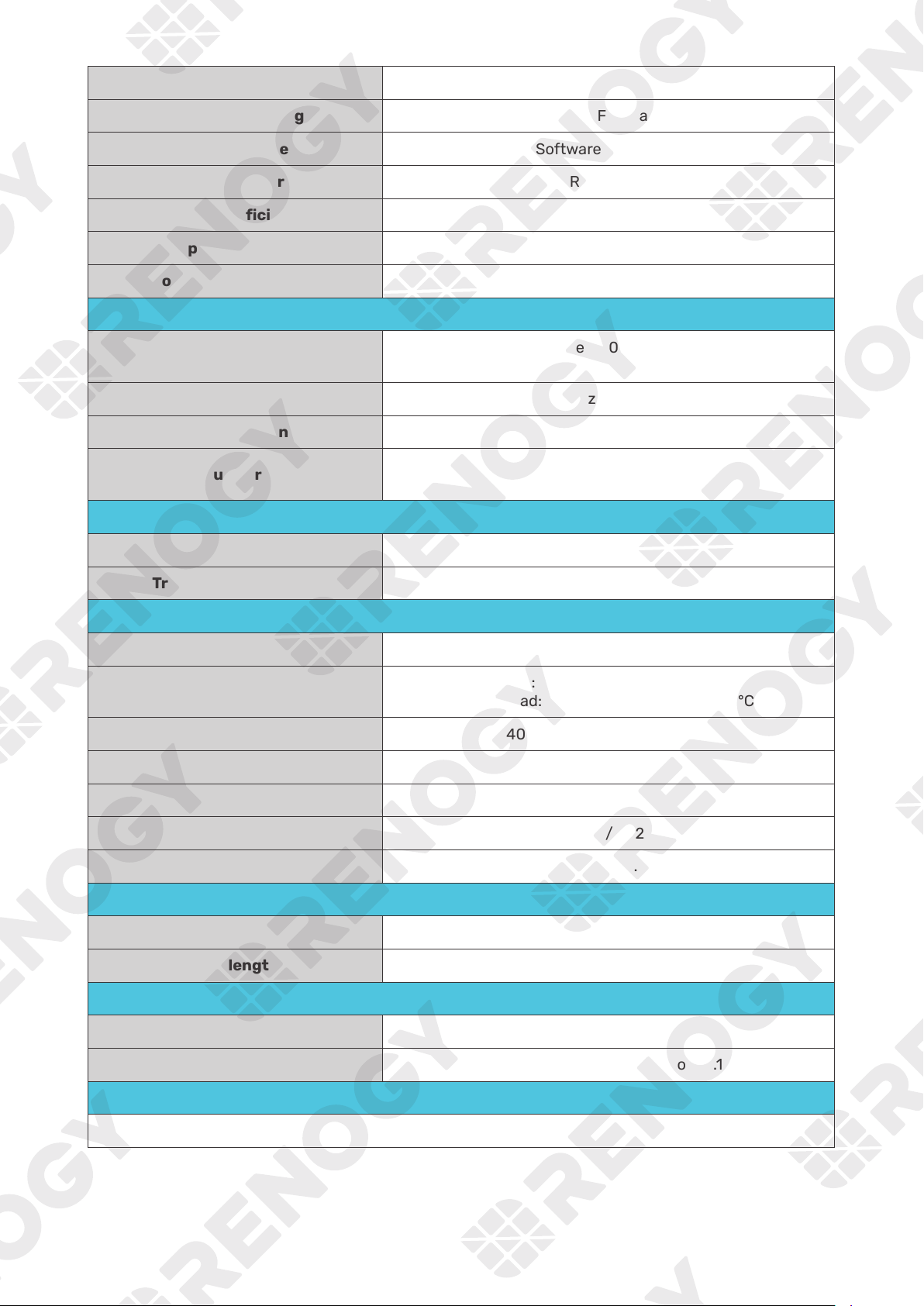
— 50 —
Nominal Input Voltage 12V DC
Input Voltage Range 9V to 17V DC (±0.3V) (Full load 11V to 15.8V DC)
Short Circuit Protection Software Protection
Total Harmonics Distortion (THD) < 3% (Resistance load)
Nominal Efficiency > 91% peak
No load power Consumption < 20W (Normal)
Short Circuit Protection Circuit Breaker
Charger Specifications
Nominal Input Voltage
Split phase: 180V to 280V AC
Single phase: 90V to 140V AC
Input Frequency Range 50Hz (±5Hz) / 60Hz (±5Hz)
Optimal Efficiency > 90%
Output Current
150A @25°C, 5A to 150A adjustable,
5A intervals, default 150A
Transfer Switch Specifications
Transfer Time 10 ms
Transfer Relay Rating 50A Maximum Bypass @120V AC
General Specifications
Battery Types SLD, AGM, GEL, FLD, LI and USER
Operating Temperature Range
Full load: -4°F to 113°F / -20°C to 45°C
Down load: 113°F to 140°F / 45°C to 60°C
Storage Temperature -40°F to 158°F / -40°C to 70°C
Humidity 0% to 95%, RH
Noise < 54dB
Dimensions 19.37 x 13.11 x 5.31 in / 492 x 333 x 135 mm
Weight 22.7 lbs / 10.3 Kg
Wired Remote Control
Dimensions 2.8 x 4.3 x 1.3 in / 70 x 110 x 31.8 mm
Wire length Approx 16.4ft
Certifications
EMC certification FCC Prat15 Class B
Safety UL-485 and CSA-C22.2 No 107.1
Warranty
5 Years
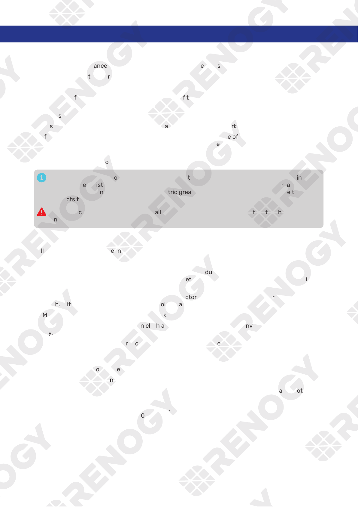
— 51 —
11. Maintenance
11.1. Inspection
For optimum performance, it is recommended to perform these tasks regularly.
z
Ensure the inverter charger is installed in a clean, dry, and ventilated area.
z
Ensure there is no damage or wear on the cables.
z
Ensure the firmness of the connectors and check if there are any loose, damaged or burnt
connections.
z
Make sure the indicators are in proper condition.
z
Ensure there is no corrosion, insulation damage, or discoloration marks of overheating or burning.
z
If the inverter charger is dirty, use a damp cloth to clean the outside of the device to prevent dust
and dirt from accumulating. Before the inverter charger is powered on, make sure it is completely dry
after cleaning.
z
Make sure the ventilation holes are not blocked.
In some applications, corrosion may exist around the terminals. Corrosion can loosen springs
and increase resistance, leading to premature connection failure. Apply dielectric grease to
each terminals contact periodically. Dielectric grease repels moisture and protects the terminals
contacts from corrosion.
Risk of electric shock! Make sure that all power supplies are turned off before touching terminals
on the inverter charger.
11.2. Cleaning
Follow the steps below to clean the inverter charger regularly.
z
Disconnect all cables connected to the inverter charger.
z
Wear proper protective equipment and use insulated tools during operation. Be careful when
touching bare terminals of capacitors as they may retain high lethal voltages even after power is
removed.
z
Wipe the housing of the inverter charger and connector contacts with a dry cloth or nonmetallic
brush. If it is still dirty, you can use household cleaners.
z
Make sure the ventilation holes are not blocked.
z
Dry the inverter charger with a clean cloth and keep the area around the inverter charger clean and
dry.
z
Make sure the inverter charger is completely dry before reconnecting it to the battery and AC input.
11.3. Storage
Follow the tips below to ensure that the inverter charger is stored well.
z
Disconnect all cables connected to the inverter charger.
z
By applying dielectric grease to each terminals, the dielectric grease repels moisture and protects
the connector contacts from corrosion.
z
Store the inverter charger in a well-ventilated, dry, and clean environment with the temperature
between -40°F to 158°F (-40°C to 70°C).
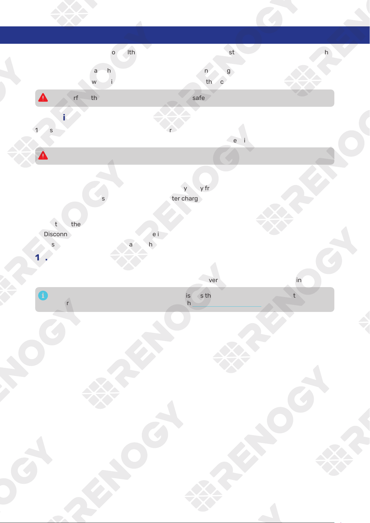
— 52 —
12. Emergency Responses
In the event of any threat to health or safety, always begin with the steps below before addressing other
suggestions.
z
Immediately contact the fire department or other relevant emergency response team.
z
Notify all people who might be affected and ensure that they can evacuate the area.
Only perform the suggested actions below if it is safe to do so.
12.1. Fire
1. Disconnect all cables connected to the inverter charger.
2.
Do not use type D (flammable metal) fire extinguishers.
12.2. Flooding
1. If the inverter charger is submerged in water, stay away from the water.
2. Disconnect all cables connected to the inverter charger.
12.3. Smell
1. Ventilate the room.
2. Disconnect all cables connected to the inverter charger.
3. Ensure that nothing is in contact with the inverter charger.
12.4. Noise
1. Disconnect all cables connected to the inverter charger.
2. Make sure no foreign objects are stuck in the fan of the inverter charger or the ring terminal.
The normal noise value of the inverter charger is less than 54dB during operation. If the noise is
abnormal, contact our technical service through renogy.com/contact-us.
— 53 —
Renogy Support
To discuss inaccuracies or omissions in this quick guide or user manual, visit or contact us at:
renogy.com/support/downloads
contentservice@renogy.com
Questionnaire Investigation
To explore more possibilities of solar systems, visit Renogy Learning Center at:
renogy.com/learning-center
For technical questions about your product in the U.S., contact the Renogy technical support team
through:
renogy.com/contact-us
1(909)2877111
For technical support outside the U.S., visit the local website below:
Canada ca.renogy.com China www.renogy.cn
Australia
au.renogy.com Japan renogy.jp
South Korea kr.renogy.com Germany de.renogy.com
United Kingdom uk.renogy.com Other Europe eu.renogy.com

— 54 —
FCC
FCC Statement
This device complies with Part 15 of the FCC Rules. Operation is subject to the following two conditions:
(1) This device may not cause harmful interference.
(2) This device must accept any interference received, including interference that may cause undesired
operation.
Any Changes or modifications not expressly approved by the party responsible for compliance could
void the user’s authority to operate the equipment.
This equipment has been tested and found to comply with the limits for a Class B digital device,
pursuant to Part 15 of the FCC Rules. These limits are designed to provide reasonable protection against
harmful interference in a residential installation. This equipment generates, uses and can radiate radio
frequency energy and, if not installed and used in accordance with the instructions, may cause harmful
interference to radio communications. However, there is no guarantee that interference will not occur in a
particular installation. If this equipment does cause harmful interference to radio or television reception,
which can be determined by turning the equipment off and on, the user is encouraged to try to correct
the interference by one or more of the following measures:
(1) Reorient or relocate the receiving antenna.
(2) Increase the separation between the equipment and receiver.
(3) Connect the equipment into an outlet on a circuit different from that to which the receiver is
connected.
(4) Consult the dealer or an experienced radio / TV technician for help.
FCC Radiation Exposure Statement
This equipment complies with FCC radiation exposure limits set forth for an uncontrolled environment.
This equipment should be installed and operated with minimum distance 20 cm between the radiator &
your body.
— 55 —
RENOGY.COM
Renogy aims to empower people around the world through education and distribution of DIY-friendly
renewable energy solutions.
Renogy Power Plus allows you to stay in the loop with upcoming solar energy innovations, share your
experiences with your solar energy journey, and connect with like-minded people who are changing
the world in the Renogy Power Plus community.
We intend to be a driving force for sustainable living and energy independence.
footprint by reducing the need for grid power.
Renogy Empowered
Live Sustainably with Renogy
Did you know? In a given month, a 1kW solar energy system will...
Save 170 pounds of coal from being burned
Save 300 pounds of CO from being released into the atmosphere
Save 105 gallons of water from being consumed
@Renogy Solar @Renogy
Renogy Power
PLUS
Renogy reserves the right to change the contents of this manual without notice.
5016367
IC: 23590-RIV1230RCH
Contains TX FCC ID: 2ANPB-RIV1230RCH
