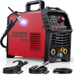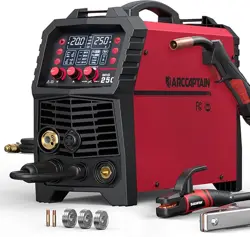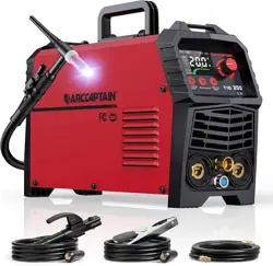

Dear Valued Customer,
Thank you very much for being our valued customer. ARCCAPTAIN welder was built by high quality
components, every single unit machine was passed multiple industry leading
laboratory tests to provide a great welding experience and performance.
For your safety, please read and understand this manual carefully before using this product. Your satisfaction
is our priority! For any question or concerns, please do not hesitate to contact ARCCAPTAIN for SUPPORT :
service@arccaptain.com
www.arccaptain.com

Contents
1. Safety Precautions ...........................................................................................................................................1
1.1 Installation Precautions ............................................................................................................................ 1
1.2 Operation Precautions ..............................................................................................................................2
1.3 Scrap Disposal ..........................................................................................................................................3
2. Product Overview .............................................................................................................................................3
2.1 Product Model Description ....................................................................................................................... 3
2.2 Product Feature ........................................................................................................................................ 3
3. Technical Parameters ...................................................................................................................................... 4
3.1 Technical Parameters ............................................................................................................................... 5
3.2 External (Static) Characteristic Curve ......................................................................................................5
4. Function and Description ................................................................................................................................6
4.1 Panel Structure and Description .............................................................................................................. 6
4.2 TIG200PACDC Panel ............................................................................................................................... 6
4.3 Functional Description .............................................................................................................................. 9
5. Installation and connection .......................................................................................................................... 16
5.1 Connection of Power Cord ..................................................................................................................... 16
5.2 Connection of power distribution box .....................................................................................................17
5.3 Welder Installation .................................................................................................................................. 17
6. Function and Operation ................................................................................................................................ 19
6.1 TIG Introduction ...................................................................................................................................... 19
6.2 MMA Introduction ....................................................................................................................................23
6.3 MMA Welding ..........................................................................................................................................23
7. Precautions & Maintenance ..........................................................................................................................26
7.1 Precautions .............................................................................................................................................26
7.2 Maintenance ........................................................................................................................................... 28
8. Trouble shooting ............................................................................................................................................28
8.1 Common Malfunction Analysis and Solution ..........................................................................................28
8.2 TIG Problems and Elimination ................................................................................................................29
8.3 Welding Procedure Checklist (for reference only) ................................................................................. 30
8.4 SMAW Process Parameters ...................................................................................................................30
https://www.arccaptain.com/
1
1. Safety Precautions
1.1 Installation Precautions
Warning: It is important that operators of this machine protect yourselves and others
from harm or even death. For details, please refer to the operator's safety protection
guide that meets the manufacturer's accident prevention requirements.
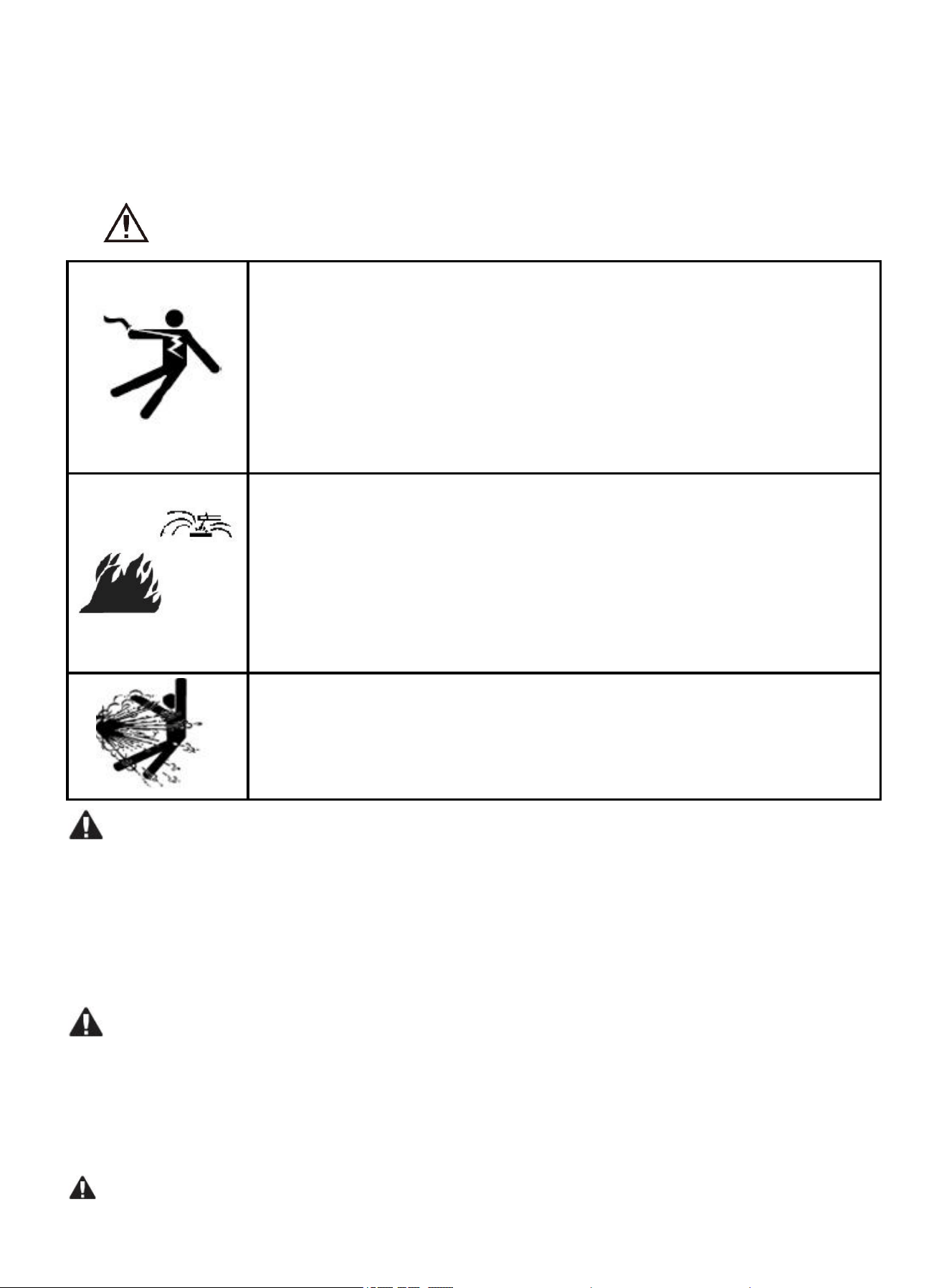
Electric shock!
Install the grounding device according to the applicable standards.
Do not touch live parts when the skin is exposed, wearing wet gloves or
wearing wet clothes.
Make sure you are insulated from the ground and the weldment.
Do not use the machine with the covers removed.
Make sure your station is safe.
Fire!
Install the welder in a dry indoor environment, and ensure that the machine is
at least 30 cm away from walls or other objects.
Ensure that there is no flammable material near the welding station; otherwise,
there will be a fire hazard.
Ensure that there are fire extinguishing devices nearby and that a trained
person can skillfully use the fire extinguisher.
Explosion!
The welder can be installed in the environment with waste gas and dust
generated by general welding, but cannot be installed in the environment with
flammable gas or metal dust; otherwise, welding sparks may cause explosion.
Moving the welder may be dangerous
Please turn off the power of distribution box before moving the welder.
When moving the welder with lifting device, please ensure the lifting eye screws are tightened and the
welder cover is installed properly.
When the welder is damaged or missing parts, do not open or use it; otherwise, it may cause fire or
personal injury.
Changing parts can be dangerous
Only professional personnel can change the machine parts. When replacing parts, do not to drop foreign
objects such as conductor trace lines, screws, washers, metal rods, etc. into the inside of the machine.
When replacing the circuit board, ensure that the wiring is correct and the machine works normally;
otherwise, it may cause property damage.
Installation environment.
https://www.arccaptain.com/
2
Avoid installing the machine in an environment with dust or metal powder;
Avoid installing the machine in an environment with corrosive or explosive gas;
Ensure that the working environment is between -10°C and 40°C. If it is used in an environment higher
than +40℃, additional forced cooling measures or derating should be taken;
It should be used in an environment where the humidity is less than 90% and there are no condensation
water beads;
Please make sure that there is no wind on the welding side. Use a windshield if necessary; otherwise, it
will affect the welding quality.
Please consult and confirm with experienced personnel first for any special Installation requirements.
1.2 Operation Precautions
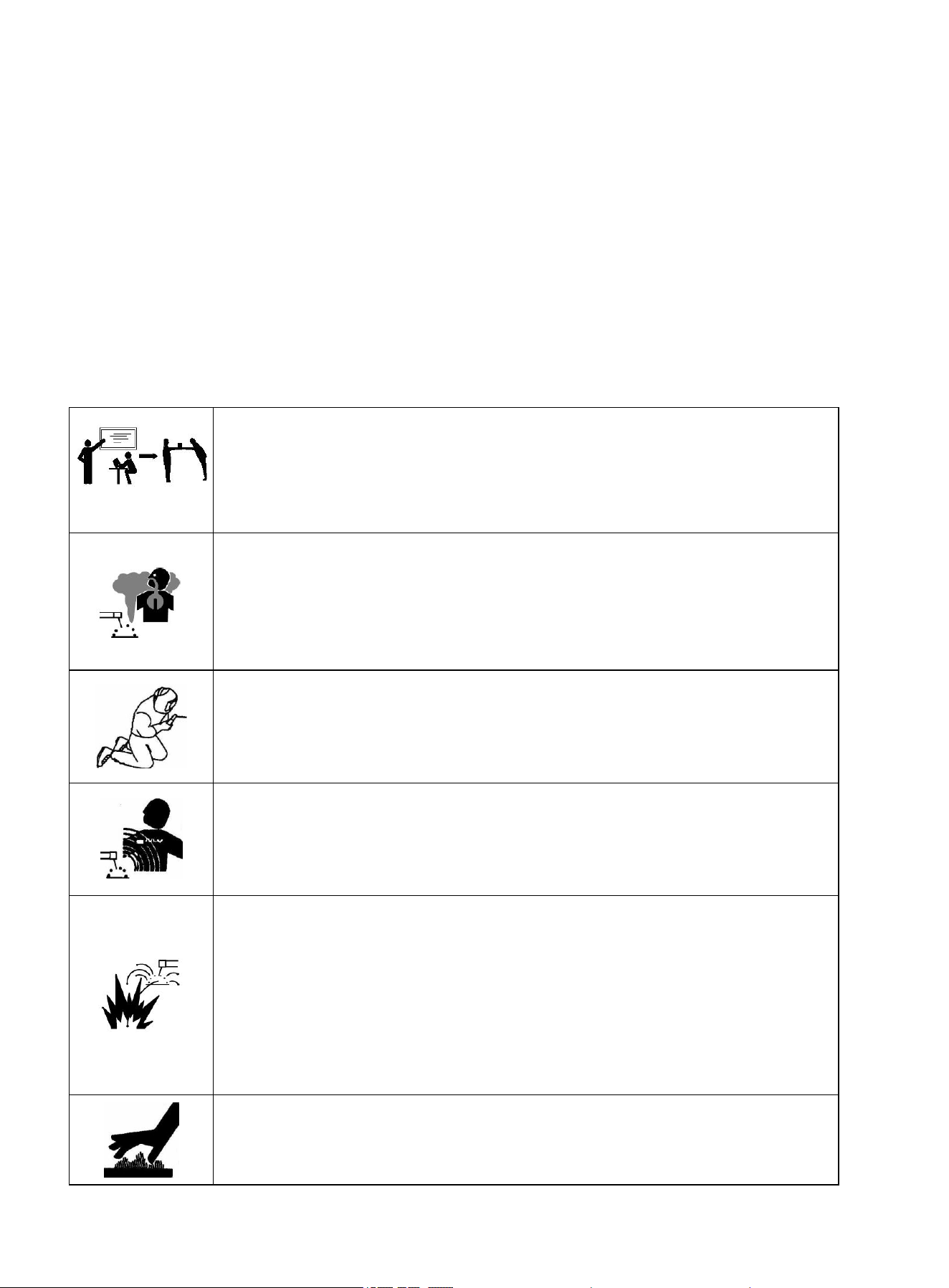
Only qualified personnel should operate this machine!
Always use the appropriate personal protective equipment.
The operator shall be a special operator with a valid "Metal Welding (Oxygen
Cutting) Operation" certificate.
Do not carry out any maintenance with the power on the machine
Fumes and gases may be hazardous to your health!
Welding may produce hazardous fumes and gases. Do not breathe the
welding fume.
Keep your head out of the welding fume, and ensure the welding zone is
provided with ventilation or fume extraction system.
Arc rays may injure the eyes and burn the skin!
Use a suitable welding helmet and wear protective clothing to protect your
eyes and body.
Use adequate helmet or protective screens to protect others from injury.
Magnetic field affects cardiac pacemaker
Pacemaker users should consult a doctor before performing welding
operations.
Stay away from welding power source to reduce electromagnetic interference.
Improper use and operation may cause fire or explosion
Welding sparks may cause fire. Please confirm that there are no combustibles
near the welding station and pay attention to safety and fire prevention.
Ensure that there are fire extinguishers nearby and that a trained person can
skillfully use the fire extinguisher.
Do not weld closed containers.
It is forbidden to use the machine for pipeline thawing.
Hot weldments can cause severe burns
Do not touch any hot surfaces or parts bare handed.
Always allow the welding gun to cool down when using it continuously.
https://www.arccaptain.com/

3
Pulse / AC / DC
Rated welding current
Gas tungsten arc welding
Moving parts may cause personal injury
Keep away from moving parts (such as fans).
Protective devices such as doors, panels, covers and baffles shall be tightly
closed and in place.
Seek professional help when encountering problems
If you still do not fully understand or cannot solve the problem after reading
the instructions in this manual, you should contact the supplier service
center immediately for professional help.
1.3 Scrap Disposal
Please pay attention to the following when scraping the welder:
Igniting electrolytic capacitors on the main circuit or circuit board can cause an explosion;
The machine belongs to industrial waste.
2. Product Overview
2.1 Product Model Description
TIG 200PACDC
2.2 Product Feature
2.2.1 Machine Overview
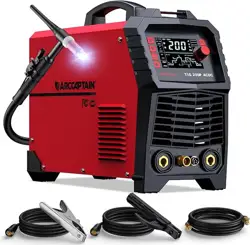
TIG200PACDC is a fully digital 7 in 1 inverter AC/DC welder with complete functions, excellent performance
and advanced technology. It supports AC TIG (square wave/triangular wave), AC pulse TIG, DC TIG, DC pulse
TIG, SMAW (DC), argon arc spot welding (DC/AC), etc.
It can be widely used in precise welding of carbon Steel, Stainless Steel, Aluminum etc, good performance in
thin Aluminum plate.
The unique “Dash-Arc” technology patent improve arc striking speed from 200ms to 40ms, 99.99% arc striking
success rate.
Digital control system makes TIG200PACDC more reliability and stability, it could adjust more parameter to
promote good performance within one LED display, such as adjustable pre-flow\Initial current\ Up-slope\ Peak
current\ Down-slope\ Crater current \ Post-flow\ AC frequency\ AC balance\ Pulse frequency. LED display
show real-time dynamic output current, easily know the output state of welder.
Automatically Parameters storage: parameters saved even after the welder is turned off and on again.
New electrical structure and “Dust free” air passage can effectively prevent damage to power devices and
control circuits from dust drawn in by the fan, thus greatly improving the reliability of the machine. Support
remote control function, could match foot pedal/analog TIG torch.
https://www.arccaptain.com/

4
2.2.3 Performance Features
Advanced IGBT inverter technology
The inverter frequency is 43KHz, which significantly reduces the loss of copper and iron, improves the
efficiency of the whole machine, and saves energy.
The main power electronics use spike withstanding IGBT, smaller volume and high reliability.
Leading digital control method
Adopt the internationally-leading MCU intelligent digital control technology, welding functions,
performance and welding procedure requirements all have been greatly improved.
New software controlled, easy to upgrade and maintain.
Excellent welding ability in TIG&MMA
Achievable high-quality MMA welding: easier arc ignition, stable welding current, little spatter, and
well-formed weld, support acid/alkaline electrodes.
The unique “Dash-Arc” technology patent improve arc striking speed from 200ms to 40ms, 99.99% arc
striking success rate. Digital constant current regulation technology ensures low noise and high stable arc
quality in the full specification.
TIG weld supports three typical TIG operation methods: two-step, four-step and spot welding, providing a
good way for users to meet special process requirements.
AC TIG can be widely used in welding of various aluminum alloys, magnesium alloys and other
non-ferrous metals, and has various waveform options.
DC TIG welding can be used for welding of various stainless steels and carbon steels.
Friendly human-computer interface and beautiful structure design
Big size LED display provide a simple, intuitive and understandable human-computer interface. The layout
of the operation panel is convenient to operation.
TIG200PACDC’s front and back panels are made of high-strength engineering plastics, to ensure the
machine works efficiently under harsh conditions such as high impact and drop.
Enjoy excellent insulation performance.
Adopt moisture-proof, dust-proof, and anti-static design and have good corrosion resistance.
Perfect automatic protection function
The machine has a perfect protection function which provides a corresponding code prompt when
providing protection.
When the ambient temperature is too high or the machine is used overloaded, the overheat protection can
prevent the high temperature from damaging the welder.
Support remote control
The machine provides gun control and foot switch options for users to select as required.
3. Technical Parameters
https://www.arccaptain.com/
5
3.1 Technical Parameters
SN Project Name Unit Value
1 Power voltage VAC AC110V±15% AC220V±15%
2 Input frequency Hz 50
3 Rated input current A 33@TIG 35@MMA
4 Capacity of power supply KVA
6.0@TIG 7.5@MMA
5 Output current range (TIG) A 10~120 10~200
6 Output current range (MMA) A 10~110 10~160
7 Arc force range A 0~40
8 Hot start current range A
0~80
9 No-load voltage V
60
10 Rated working voltage V
18@TIG 26.4@MMA
11 AC output frequency Hz 20~250
12 AC balance % 20~60
13 Background level A 10~200
14 Pulse frequency
Hz
0.5~200 (DC) 0.5~25(AC)
15 Pulse duty factor
%
5~95
16 Pre-flow time S 0~5
17 Post-flow time S 0~15
18 Rising time S 0~15
19 Fall time S 0~15
20 Remote control -
Yes
21 Arc start mode
- HF arc starter
22 Efficiency (%) %
80
23 Duty cycle (%) % TIG: 200@25% - MMA: 160@25%
24 Power factor - 0.70
25 Type of cooling - Air cooled
26 Working temperature range °C —10~+40
27 Storage temperature range °C —25~+55
28 Protection class - IP21S
29 Insulation class - B
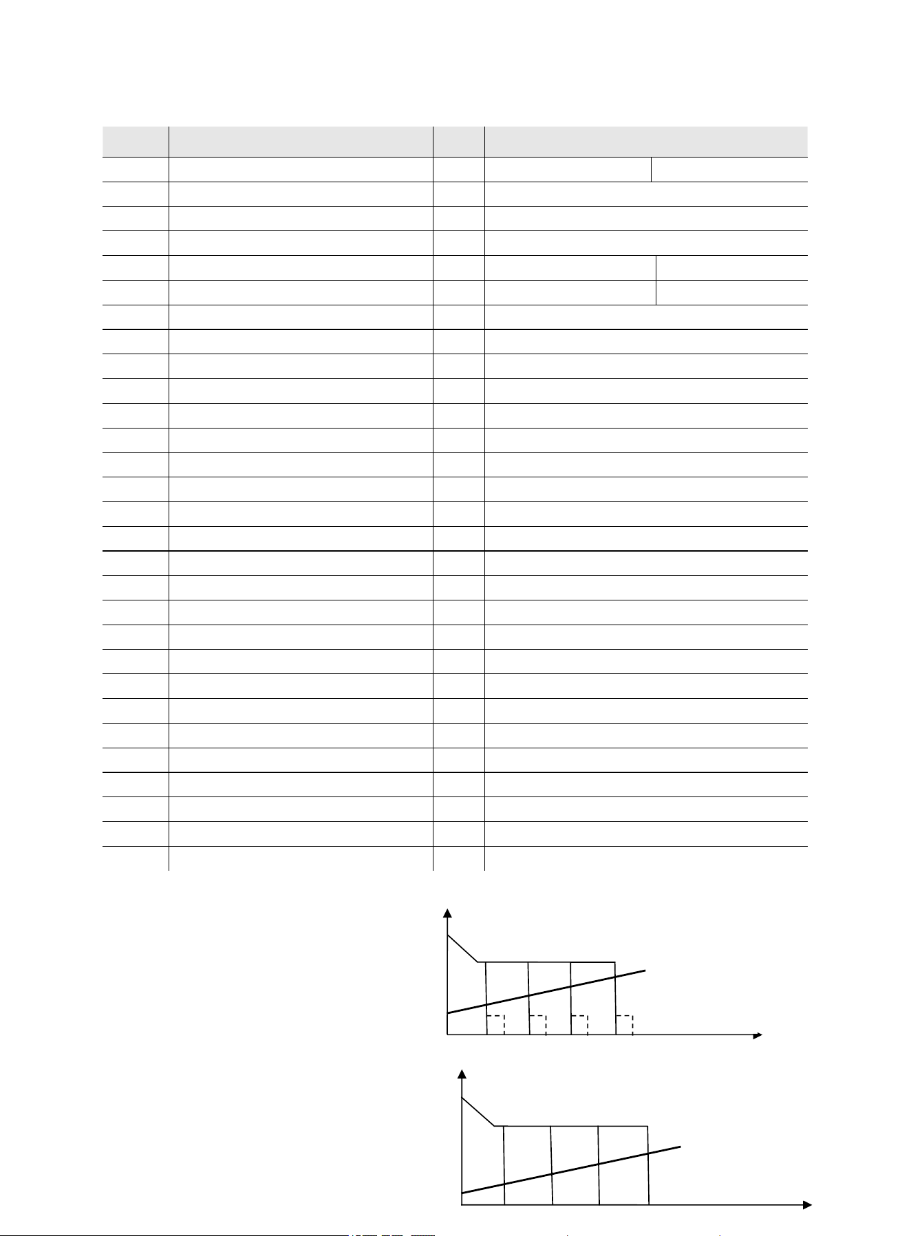
3.2 External (Static) Characteristic Curve
MMA electrode welding
has drop characteristic, and outputs
the external (static) characteristic
curve as shown in the right figure:
Simple TIG has drop characteristic,
and outputs the external (static)
characteristic curve as shown in the right figure:
MMA: U
2
=20+0.04I
2
(≦44V
)
TIG: U
2
=10+0.04I
2
(≦34V
)
U
0
I(
U(V)
U
0
I(A)
https://www.arccaptain.com/
6
4.FUNCTION AND DESCRIPTION
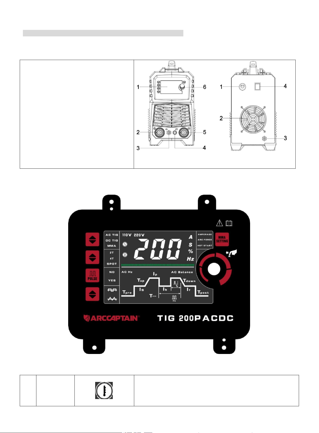
4.1 Panel Structure and Description
Pic1:
1. Digital plastic display panel
2.Positive output fast socket
3.TIG outlet interface
4.Gun control aviation socket
5. Negative output fast socket
6. Encoder
Pic2:
1. Input power cord
2.Cooling fan
3. TIG inlet nozzle
4.Power switch
Pic 1 Pic 2
4.2 TIG200PACDC Panel
Pic 3 Plastic display panel
Function table of plastic display panel
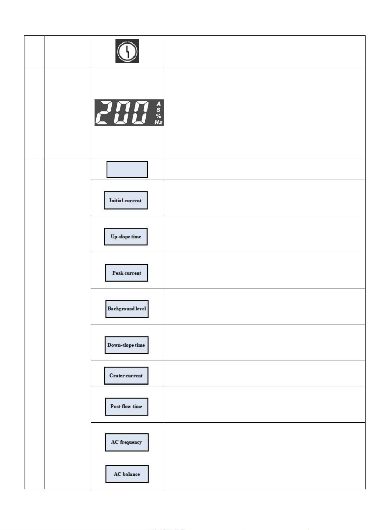
1 Protection
indicator
Overheat indicator, indicating that the temperature of internal
components is too high and the welder displays overheat
protection.
https://www.arccaptain.com/
7
Alarm indicator, indicating that the welder works abnormally.
2 Data display
The table header shows the specific value of the parameters;
"A" is current unit indicator. The indicator will flash when there is
current;
"S" is time unit indicator. The indicator will be on when the time
is displayed.
"%" is percentage indicator. The indicator will be on when the
percentage is displayed.
"Hz" is frequency unit indicator. The indicator will be on when the
frequency is displayed;
3
TIG
Parameters
Pre-flow time indicator. When the indicator is on, it indicates the
pre-flow protection time.
Initial current indicator. When the indicator is on, it indicates
the initial current.
Up-slope time indicator. When the indicator is on, it indicates
the time when the initial current reaches the peak current.
Peak current indicator. When the indicator is on, it indicates the
welding current.
Background level indicator. When the indicator is on, it
indicates the background level if there is pulse.
Down-slope time indicator. When the indicator is on, it indicates
the time when the peak current drops to the crater current.
Crater current indicator. When the indicator is on, it indicates
the current when stopping arc.
Post-flow time indicator. When the indicator is on, it indicates
the delayed air-off time.
AC frequency indicator. When the indicator is on, it indicates
the AC frequency.
AC balance indicator. When the indicator is on, it indicates the
ratio of tungsten anode time to AC cycle.
Pre-flow time
https://www.arccaptain.com/
8
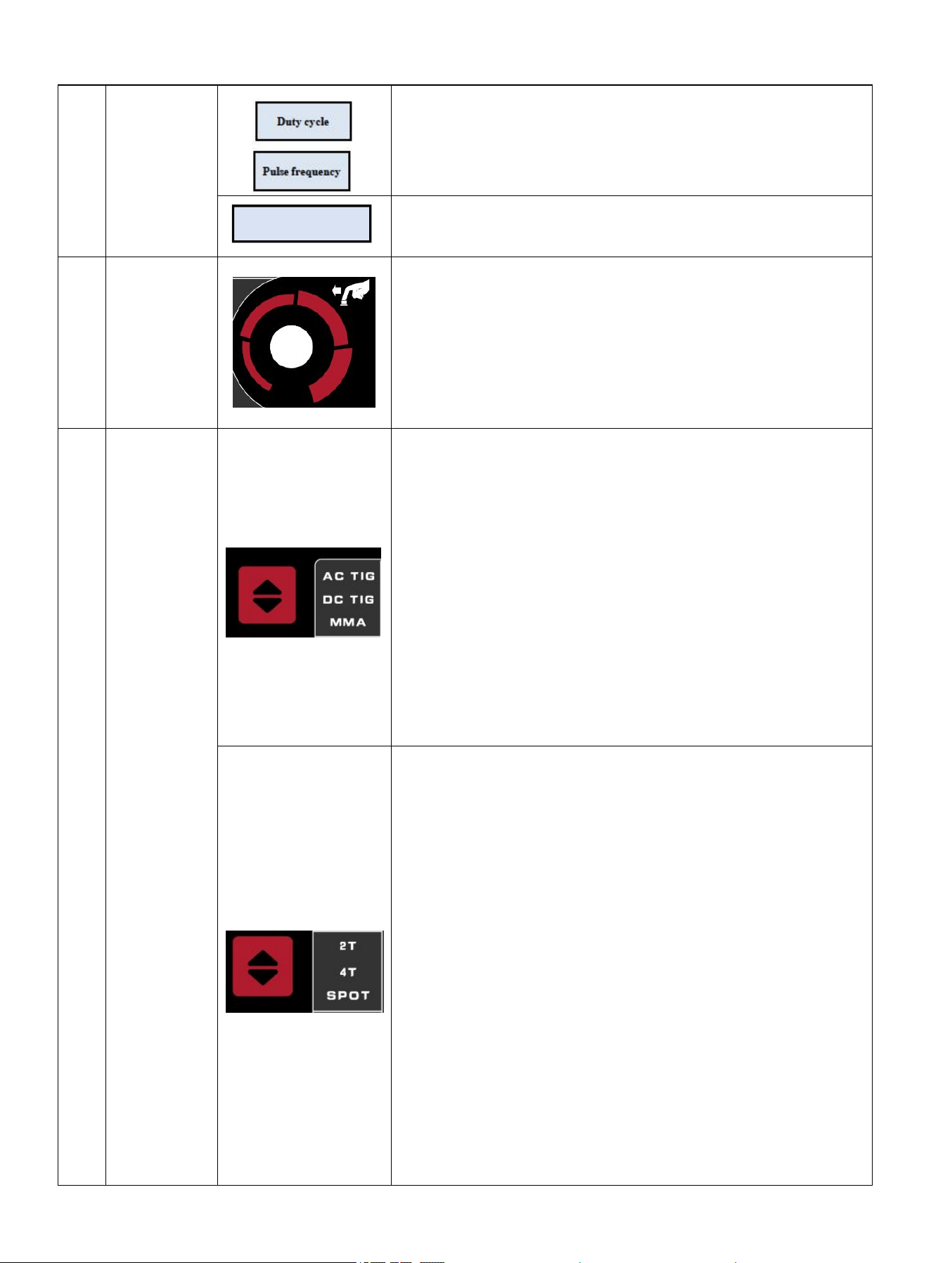
Duty-cycle indicator. When the indicator is on, it indicates the
ratio of peak current time to pulse period.
Pulse frequency indicator. When the indicator is on, it indicates
the pulse frequency.
Spot welding time indicator. When the indicator is on, it
indicates the spot welding time.
4 Encoder
Parameter setting function.
1. Rotate encoder to select the parameter to be set.
2. After pressing the encoder, the selected parameter indicator
flashes, and rotate encoder to set the parameter.
3. After setting, press the encoder to exit settings.
5 Function
Selection
1. Press the welding mode button to switch the welding mode.
2. MMA indicator. When the indicator is on, it indicates that the
machine is in MMA mode.
3. DC TIG indicator. When the indicator is on, it indicates that
the machine is in DC TIG mode.
DC output is suitable for welding carbon steel, copper and
stainless steel.
4. AC TIG indicator. When the indicator is on, it indicates that
the machine is in AC TIG mode.
AC output is suitable for welding aluminum, magnesium and
their alloys.
1. Press the operation mode key to switch the operation mode.
Spot welding indicator. When the indicator is on, it indicates that
the machine is in spot welding mode.
In spot welding mode, press the torch trigger will reach the
preset current state after the pre-flow time. Spot welding will turn
off the output after the set running time.
2. Four-step indicator. When the indicator is on, it indicates that
the machine is in four-step mode.
In four-step mode, press the torch trigger, the machine will stop
at the initial current phase after the pre-flow time; release the
torch trigger, the machine will reach the peak current phase after
the up-slope time from initial current to peak current; press the
torch trigger again, the machine will stop at the final current
phase after the down-slope time from peak current to crater
current; and then release the torch trigger, the machine will start
gas supply after the crater current extinguishes.
3. Two-step indicator. When the indicator is on, it indicates that
Spot welding time
https://www.arccaptain.com/
9
the machine is in two-step mode.
In two-step mode, press the torch trigger, the machine will reach
the peak current after the pre-flow time and up-slope time from
initial current to preset current; release the torch trigger, the
machine will start gas supply after the preset current drops to
crater current and then extinguishes.
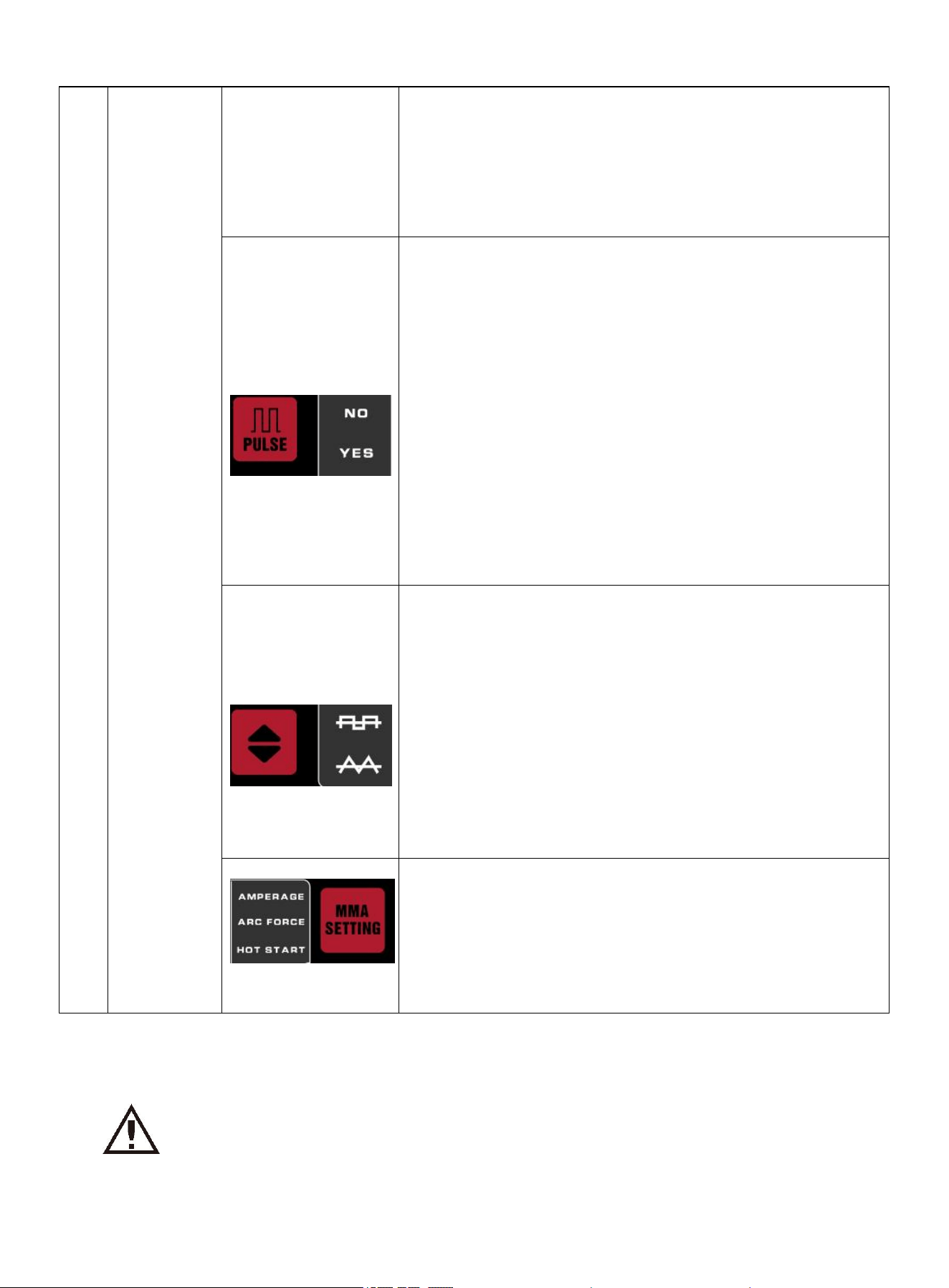
1. Press pulse key to switch between pulse and no pulse.Pulse
indicator. When the indicator is on, it indicates the pulse state.
2.Generally, the low-frequency pulse frequency is 0.5-10Hz. The
interactive effect of heating and cooling can reduce deformation
by reducing the average current. Low-frequency pulse current,
coupled with proper welding speed, can form fish-scale welds.
Besides, it is convenient to use wire filling device under
low-frequency pulse to optimize the weld formation. Pulse can
oscillate the molten pool and improve the microstructure of weld.
High-frequency pulse can enhance the concentration and
stiffness of the arc. Stable arc can increase the depth of molten
pool and improve welding speed.
3. No-pulse indicator. When the indicator is on, it indicates there
is no pulse.
1. Press the waveform selection key to switch the output
waveform in AC mode.
2. Triangular wave indicator. When the indicator is on, it
indicates that triangular wave is selected.
The triangular wave reduces the heat input, so the weld can
form rapidly, reducing the welding deformation. It is suitable for
thin-plate welding.
3. Square wave indicator. When the indicator is on, it indicates
that the machine selects square wave.
Standard AC square wave can quickly switch the polarity,
enjoying high arc stability, good dynamic characteristics, and
strong ability to clean aluminum oxide film. It is suitable for a
wide range of aluminum and aluminum alloy welding.
1. Press the MMA parameter key to switch the function
selection.
2. Hot start indicator. When the indicator is on, it indicates that
hot start current of MMA is selected.
3. Arc-force current indicator. When the indicator is on, it
indicates that the arc-force current of MMA is selected.
4. Welding current indicator. When the indicator is on, it
indicates that the welding current of MMA is selected.
4.3 Functional Description
Warning! Select the welding function according to requirements. The welding
mode and parameters should be selected according to the technical
requirements of the weldment. If the welding mode or parameters are not
appropriate, there will be unstable arc, big spatter, sticking electrode, etc.
https://www.arccaptain.com/

10
4.3.1 TIG200PACDC Function Table
Rotate the encoder to select different welding parameters according to actual requirements. Regardless in
no-load or welding mode, the parameter selection and adjustment can be carried out without affecting the
welding. The mode is switched by rolling mode. "●" indicates that the parameter is optional, and "×" means that
the parameter is not optional.
Welding mode Torch trigger mode MMA current Hot start current Arc-force current
MMA None ● ● ●
Welding
mode
Torch
trigger
mode
Pre-flo
w
time
Initial
current
Up-sl
ope
time
Peak
current
Backgro
und
level
Down-
slope
time
Crater
curren
t
Post-fl
ow
time
Spot
welding
time
AC
freque
ncy
AC
balance
Pulse
frequency
Pulse
duty
factor
DC TIG
Two-ste
p
● ● ● ● × ● ● ● × × × × ×
Four-st
ep
● ● ● ● × ● ● ● × × × × ×
Spot
welding
● × × ● × × × ● ● × × × ×
DC
pulse
TIG
Two-ste
p
● ● ● ● ● ● ● ● × × × ● ●
Four-st
ep
● ● ● ● ● ● ● ● × × × ● ●
Spot
welding
× × × × × × × × × × × × ×
AC TIG
Two-ste
p
● ● ● ● × ● ● ● × ● ● × ×
Four-st
ep
● ● ● ● × ● ● ● × ● ● × ×
Spot
welding
● × × ● × × × ● ● × × × ×
AC TIG
pulse
Two-ste
p
● ● ● ● ● ● ● ● × ● ● ● ●
Four-st
ep
● ● ● ● ● ● ● ● × ● ● ● ●
Spot
welding
× × × × × × × × × × × × ×
https://www.arccaptain.com/
11
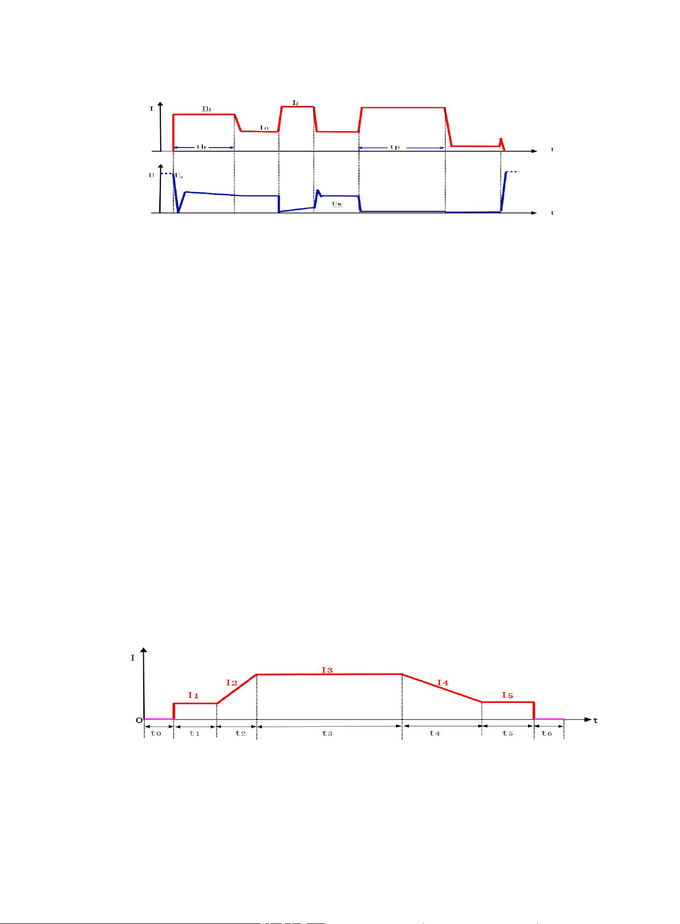
4.3.2 MMA Function
Pic 4 Welding process of manual electrode
1. I
h
(hot start current) = I
Δh
(arc ignition current)+ I
a
(welding current); the hot start time is fixed at t
h
, which is
conducive to arc starting, and reduce the sticking tendency of welding electrode and weldment during arc
ignition.
The magnitude of hot start current is generally determined based on the type, specification, and welding
current of welding electrode. For welding rods with sound arc start performance and small diameter, generally
select small hot start current; large welding current also has little requirement for hot start current.
The hot start time is correlated with the arc starting current. The greater the hot starting current is, the shorter
the arc start time will be.
2. I
f
(plus arc-force current) = I
Δf
(arc-force current)+I
a
(welding current); the arc-force current shall be
determined according to electrode diameter, set current and process requirements. High arc force settings
lead to a faster metal transfer and non-sticking electrode but with some spatter. Lower arc force settings
provide a smooth arc with lower spatter and a good weld seam formation, but sometimes the arc is soft or the
welding rod can stick. In particular, heavy welding electrodes shall be welded at low currents with increased
arc force. Generally, the arc force is 2070A when welding.
3. After the short-circuit time exceeds Tp, it will enter the anti-sticking electrode current, which is small current
until the electrode is separated from the weldment.
4. U
0
is open circuit voltage and Uw is working voltage. When MMA is not working, the welder outputs the open
circuit voltage is U
0
.
4.3.3 TIG Function
1) DC TIG
Pic 5 Current change waveform of DC TIG
t0-Pre-flow time
I1-Initial current t1-Initial current period
I2-Current corresponding to the up-slope time t2-Up-slope time
https://www.arccaptain.com/
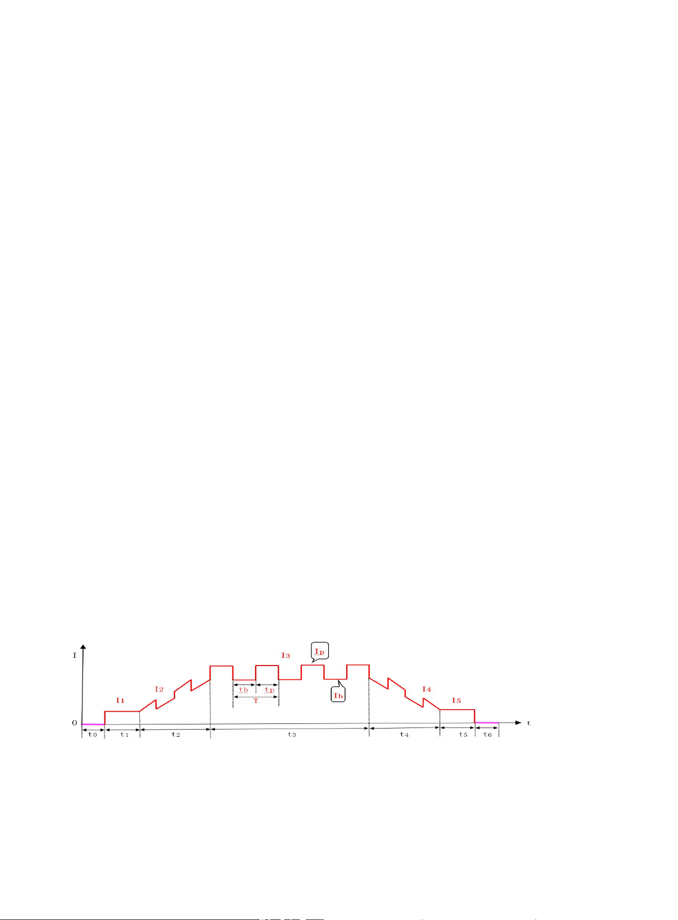
12
I3-Peak current t3-Peak current period
I4-Current corresponding to down-slope time t4-Down-slope time
I5-Crater current t5-Crater current period
t6-Post-flow time
● Initial current (I1): The initial current is the current after the gun torch trigger is pressed to ignite the arc,
which should be determined according to the process requirements. Large initial current is easy to ignite
the arc, but it should not be too large when welding the thin plate; otherwise, it is easy to burn through the
weldment. After the arc is ignited in some operations, the current stays at the initial current and does not
go upslope to achieve the purpose of preheating the workpiece or lighting.
● Up-slope time (t2): The up-slope time refers to the time when the current slowly rises from the initial
current to the peak current, which can be determined according to the use and process requirements.
● Peak current (I3): The parameter is set by the user according to the process requirements.
● Down-slope time (t4): Down-slope time refers to the time when the current drops from the peak current to
the crater current, which can be determined according to the use and process requirements.
● Crater current (I5): In some operating modes, the arc is not extinguished after down-slope of current and
maintains in a state of continuous arc. The operating current in this state is called the crater current, which
can avoid weld defect or large crater caused by immediate cutting off the output. The current shall be
determined according to the process requirements.
● Pre-flow time (t0): It refers to the time from pressing the torch trigger to send argon gas to arc ignition.
Generally, it should be greater than 0.5s to ensure that the argon gas has been sent to the welding gun at
normal flow when discharging arc initiation, especially when the gas pipe is long, the pre-flow time should
be increased.
● Post-flow time (t6): It refers to time from cutting off welding current to turning off gas valve in welder. Too
long time will cause waste of argon gas, but too short time will cause oxidation of weld. The time shall be
longer for AC TIG and special material welding.
2) DC Pulse TIG
Pic 6 Current change waveform of DC Pulse TIG
I1-Initial current t0-Pre-flow time
I2-Current corresponding to the up-slope time t1-Initial current period tb-Pulse base time
I3-Set pulse current t2-Up-slope time tp-Pulse peak time
https://www.arccaptain.com/
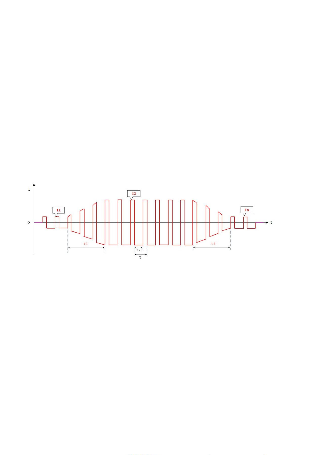
13
I4-Current corresponding to down-slope time t3-Peak current running period T-Pulse period
I5-Crater current t4-Down-slope time
IP-Pulse peak current t5-Crater current period
Ib-Pulse background level t6-Post-flow time
Pulse TIG includes all parameters of DC TIG, except that the parameters are set differently. The same
parameters will not be repeated here. In addition, there are 4 adjustable parameters, which are explained
separately in conjunction with the figure:
● Peak current (Ip): It is adjusted according to the process requirements.
● Background level (Ib): It is adjusted according to the process requirements.
● Pulse frequency (1/T): T=tp+tb, adjusted according to the process requirements.
● Duty cycle (100%*tp/T): Duty cycle is the percentage of peak current duration in the pulse cycle, which is
adjusted according to the process requirements.
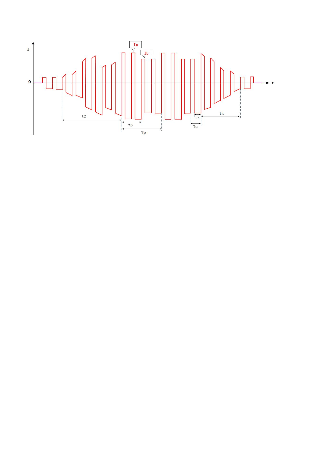
3) AC TIG
Pic 7 Current change waveform of AC TIG
I1-Initial current t2-Up-slope time
I3-Set AC peak current t4-Down-slope time
I5-Crater current tc-Clearing current time
T-AC period
AC TIG supports square wave, triangular wave and sine wave, but the output waveforms are different.
Except for the same pre-flow time and post-flow time for AC TIG and DC TIG, other parameters are explained
separately in conjunction with the figure:
● Initial current (I1), peak current (I3) and crater current (I5): The set values of these three parameters are
approximately equal to the effective values of the actual welding current, which can be adjusted according to
the process requirements.
● AC frequency (1/T): It can be adjusted according to the process requirements.
● Ac balance (100%*tc/T): Generally, the current of positive tungsten electrode in AC welding is called the
cleaning current. Its main function is to break the dense oxide layer of the workpiece, and the AC balance
represents the proportion of the cleaning current. The parameter is generally 10-40%. When the value is small,
the arc is concentrated, the fusion depth is large, and the fusion width is small, vice versa.
https://www.arccaptain.com/
14
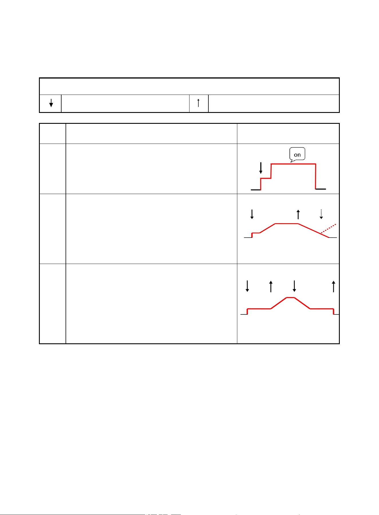
4) AC Pulse TIG
Pic 8 Current change waveform of AC pulse TIG
tc-Clearing current time Tc-AC period
tp-Pulse peak time Tp-Pulse period
t2-Up-slope time t4-Down-slope time
Ip-Peak current Ib-Background level
● AC frequency (1/Tc): It is adjusted according to the process requirement.
● Pulse frequency (1/Tp): It is adjusted according to the process requirement.
● Duty cycle (100%*tp/Tp): It is adjusted according to the process requirement.
● AC balance (100%*tc/Tc): It is adjusted according to the process requirement.
● AC pulse TIG supports square wave, triangular wave and sine wave, but the output waveforms are
different. AC pulse TIG is basically same as the AC square wave TIG, but its welding current is controlled
by a low-frequency pulse. Therefore, the welding current changes with pulse value to form peak and
background current, and the set peak and background current are the peak value (average value) and
background value (average value) of low-frequency pulse.
● In AC pulse mode, the pulse frequency range is affected by AC frequency and frequency division factor.
The minimum frequency division factor is 10, and the maximum value is 2 times the AC frequency.
Therefore, the pulse frequency range is 0.5Hz to AC frequency/10Hz, and the user can choose any
frequency in the range. When the AC frequency changes, the AC frequency/actual frequency of the
current pulse is equal to the frequency division factor and updated. When the frequency division factor is
determined, the current AC frequency/frequency division factor is equal to the actual frequency of the
current pulse and saved, so the pulse frequency does not change. After setting the AC frequency and
pulse frequency, the frequency division factor is determined, which is equal to AC frequency/pulse
frequency. For example: When AC frequency is set to 100Hz, the pulse frequency range is 0.5-10Hz. If the
AC frequency is set to 100Hz and the pulse frequency is set to 5Hz for the first time, the current frequency
division factor is 100/5=20. When the AC frequency is changed to 70Hz, the frequency division factor is
70/5=14, that is, the frequency division factor is variable, but the pulse frequency is constant. In other
words, the AC frequency affects the pulse frequency range. But when the pulse frequency is
determined, it will no longer be affected by the AC frequency.
5) Welding Mode Description of TIG Welding Gun
TIG operation mode has a special convention, which specifies the mode or method of controlling the
welding current change by different operations of torch trigger during TIG (DC, pulse, AC TIG, mixed TIG)
https://www.arccaptain.com/
15
welding. The introduction of TIG operation strengthens the application of torch trigger remote control function,
so users can obtain a practical welder remote control without increasing investment.
TIG mode should be determined according to the process requirements and users' operation habit. The
symbols in the diagram are described as follows:
Mode
No.
Agreed Operation
Torch trigger operation and
typical DC TIG current curve
1
Spot welding mode:
1. Press the torch trigger to start the arc to the set
value
2. The arc extinguishes after the spot welding finishes
the set running time
2
"Two-step" mode:
1. Press the torch trigger to start the arc slowly to the
set peak value
2. Release the torch trigger to slowly drop to the
quenching of arc
3. If the gun switch is pressed again before quenching
of arc, it will slowly rise to the peak value
3
"Four-step" mode:
1. Press the torch trigger to start the arc to the initial
value
2. Release the torch trigger to slowly rise to the peak
value
3. Press the torch trigger to slowly drop to the
stopping arc
4. Release the torch trigger to extinguish the arc
Operation legend of commonly used torch trigger
Press the torch trigger Release the torch trigger
https://www.arccaptain.com/
16
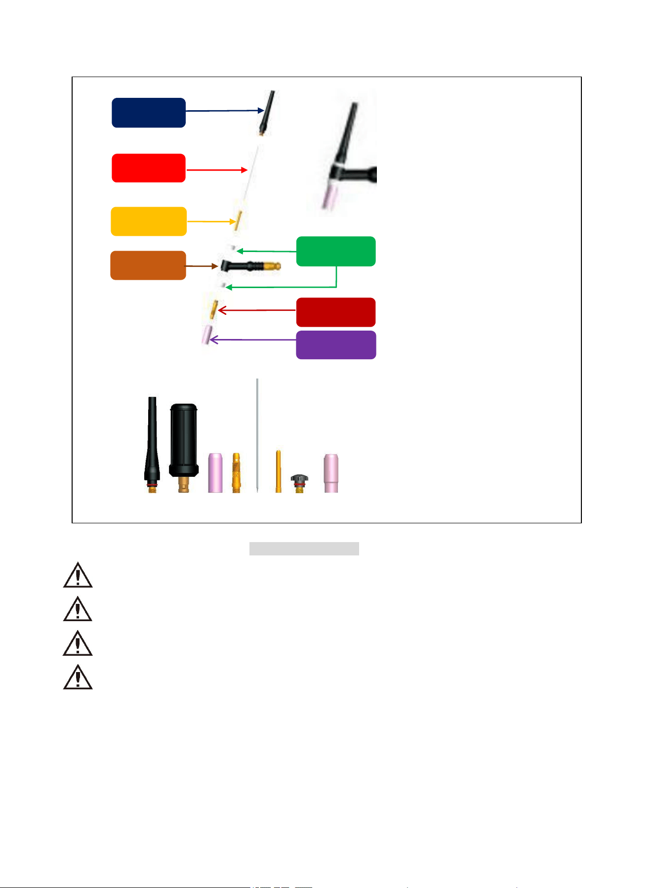
6) TIG Welding Gun Description
Long handle
ca
p
Tungsten
needle
Connecting
needle
Gun head
Insulating cap
of
g
un head
Tungsten clamp
Ceramic nozzle
Standard welding gun
parameters
Gun type: gas-electric
integrated
Maximum current: 200A
Rated current: 200A
Type of cooling: Air cooled
Gas connector: M16.5
5.INSTALLATION AND CONNECTION
Warning! Electric shock may cause death! After power failure, there is still a high
voltage on the equipment, do not touch the live parts on the equipment.
Warning! The power supply connection of the machine must be operated by
experienced and qualified electricians.
Warning! Do not ground the live wire (blue, brown, black) of the power cord, and do
not connect the earth lead (yellow-green) to the live wire.
Warning! Incorrect input voltage may damage the equipment.
5.1 Connection of Power Cord
1) This machine is equipped with a power voltage compensation system. Therefore, it can be used in the
range of rated voltage ±15%.
2) Connect the power source to the suitable power distribution box according to the voltage grade of welder.
Meanwhile, ensure that the supply voltage deviation is within the allowable range.
3) When extension cord is required, it is recommended to use cables with larger cross-sectional area to
Pic 9 Accessories
Assemble the welding gun
according to the figure
https://www.arccaptain.com/
17
reduce the voltage drop. An excessively long cable may affect arc starting performance and normal operation
of system. Therefore, please use the recommended cable length.
4) YZ 3X2.5mm² 300/500V power cord is recommended for TIG200PACDC.
Ensure that the switch of the power distribution box is turned off when connecting the input power cord.
Connect the input power cord of the welder to the output of the power distribution box reliably.
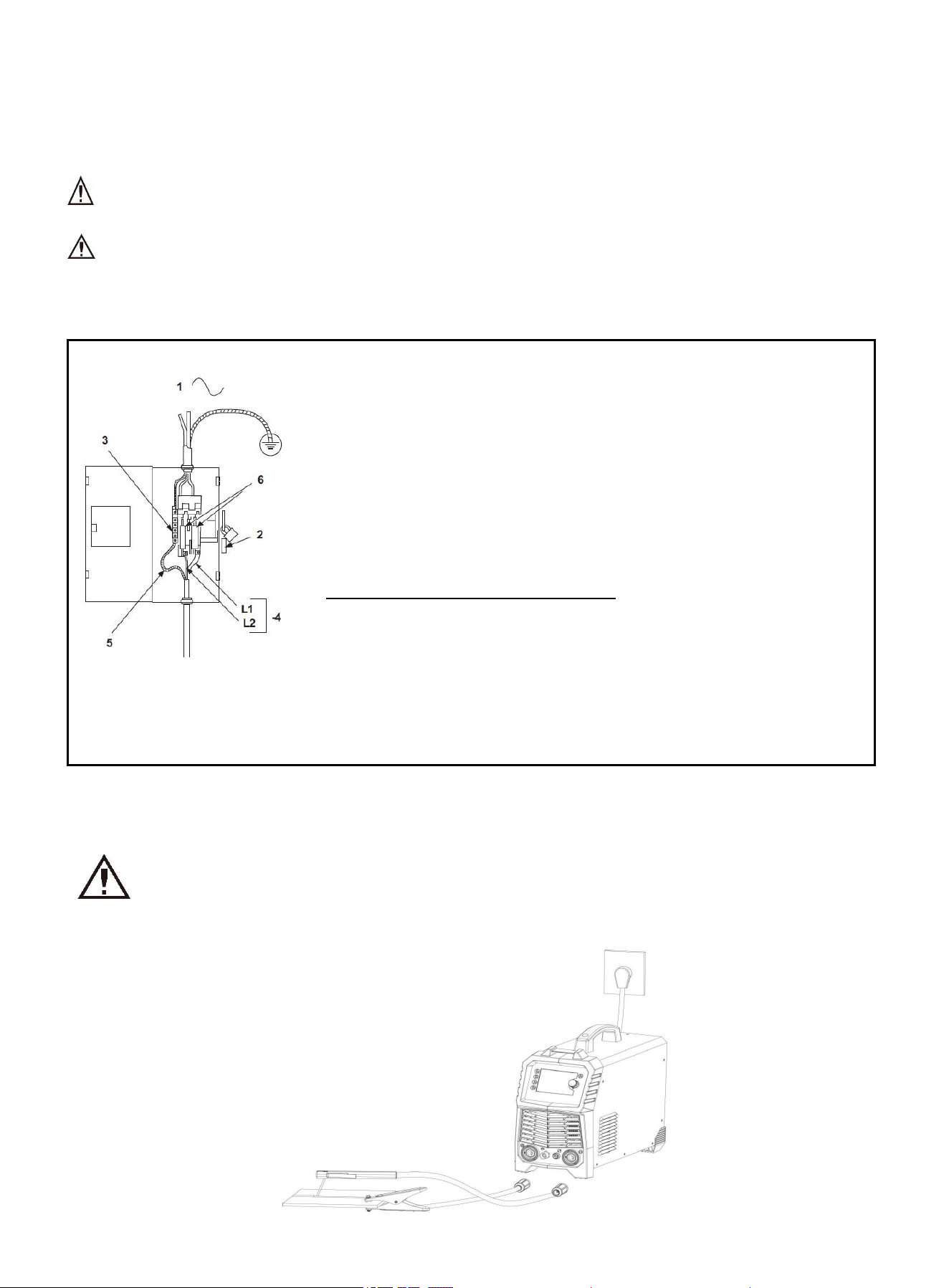
5.2 Connection of power distribution box
Wiring diagram of
single-phase power
distribution box
1. Single-phase AC power input: 110V/220V;
2. Power switch of power distribution box;
3. Earth terminal strip;
4. Welder power cable or socket adapter cable: 200A machine shall use
cable of 3*2.5mm2 or above;
5. Yellow-green earth lead (connect to the ground);
6. Fuse: 200A machine shall use fuse of no less than 60A.
Please connect the cables according to the way shown or other correct ways
with the main power switch being turned off.
Note: Do not operate with electricity.
The wiring of the machine can only be carried out by professional
electricians.
Please distinguish the input voltage 380V and 220V for single-phase
machine.
Do not connect two welders to the same distribution box.
If the enclosure is grounded, line 5 is not grounded.
5.3 Welder Installation
Warning! All connections shall be made with the power supply being turned off. The
correct steps are: first, ground the welder reliably and ensure correct wiring without
missing correction; and then connect the input power cable.
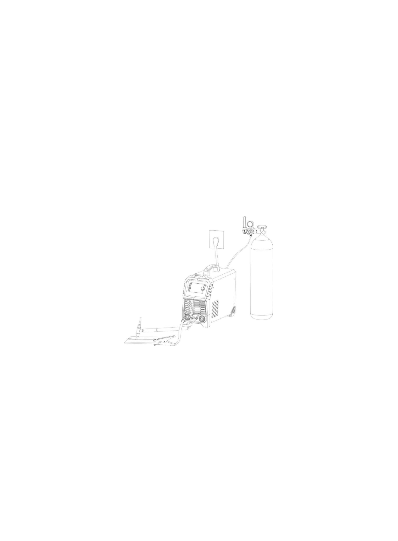
1)MMA Installation
https://www.arccaptain.com/
18
Pic 10 MMA Installation diagram
How to use:
Turn the power switch to "ON" position after correct Installation. At this time, the panel indication is on, the
fan starts rotation (which is controlled by temperature and may stop after rotation), and then the fan starts
to work normally.
Pay attention to the polarity of wiring before MMA. Generally, there are two connection methods of DC
welder: Electrode positive and electrode negative connection.
Positive connection: the welding electrode holder is connected to the negative polarity, and the weldment
is connected to the positive polarity;
Negative connection: the electrode holder is connected to the positive polarity, and the weldment is
connected to the negative polarity.
The connection method is selected according to the process requirements of the weldment. If the
selection is wrong, it will result in unstable arc, large spatter and sticking electrode, etc. At this time, the
operators can easily exchange the fast plug to change the polarity.
Select the corresponding electrode according to the current, clamp the electrode, and start welding by
short-circuit arc starting.
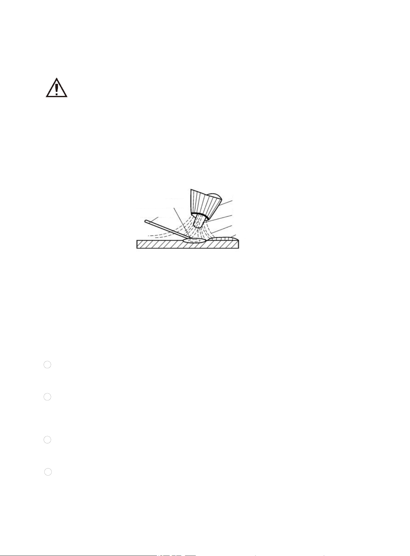
2)TIG Installation
Pic 11 TIG Installation diagram
How to use:
Connect the earth clamp to the positive polarity of welder and joint of welding gun to the negative polarity
of welder before TIG. The welding cannot be started if connected wrongly; connect the control cable of
welding gun to the control interface; select the proper welding mode according to the material of weldment
and check whether the selected tungsten electrode matches the panel parameters and whether the
current parameters match the requirements. In AC welding mode, improper AC balance parameter may
cause abnormal welding.
If the workpiece is far away from the welder. The secondary wire (welding cable and ground wire) used is
relatively long, so it is suggested that the cross-sectional area of the wire should be appropriately larger to
reduce the voltage drop of the cable.
The welding output line cannot be coiled, as this will cause the machine to work abnormally.
Select the corresponding tungsten electrode according to the current, and start welding by lift TIG or
high-frequency arc starting.
https://www.arccaptain.com/
19
6.Function and Operation
6.1 TIG Introduction
Warning! Do not disconnect the plug or cable in use during welding, otherwise
it will cause electric shock or damage to the machine!
6.1.1 TIG Overview and Characteristics
TIG is a gas shielded arc welding that uses argon as the protective gas. TIG welding process is as shown
in the figure. It uses the argon gas flow ejected from the nozzle of the welding gun to form a tightly closed
protector in the arc area to isolate the metal molten pool from the air, so as to prevent air intrusion. Besides, it
uses the heat generated by the arc to melt the filler wire and base metal, and the liquid metal molten pool will
form weld after cooling.
Pic 12 TIG diagram
Argon is an inert-gas and does not react chemically with metal, so it will not burn the alloy elements in the
metal being welded and can fully protect the metal molten pool from oxidation. Moreover, argon is insoluble in
liquid metal at high temperature, so it is not easy to cause gas pores in the weld. Therefore, argon can provide
effective and reliable protection effect, thus obtaining higher welding quality.
6.1.2 TIG Characteristics
Compared with other stud arc welding methods, TIG enjoys the following characteristics:
1 Argon has excellent protection performance, and there is no need to prepare corresponding flux during
welding. It is basically a simple process of metal melting and crystallization, which can obtain relatively pure
and high-quality welds.
2 Because the arc is compressed and cooled by the argon gas flow, the heat of arc is concentrated, and
the temperature of the argon arc is very high. Therefore, the heat-affected zone is very narrow, the welding
deformation and stress are small, and the crack tendency is small. It is especially suitable for welding of thin
plates.
3 TIG is open arc welding, which is convenient to operate and observe, making it easy to realize the
mechanization and automation of the welding process. In addition, welding in various spatial positions can be
performed under certain conditions.
4 TIG supports a wide range of weldable materials, including almost all metal materials, especially
suitable for welding chemically active metals and alloys.
It is generally used for welding aluminum, titanium, copper and their low alloy steels, stainless steels and
heat resistant steels, etc.
Because of these outstanding characteristics of TIG, with the increasing product structure of non-ferrous
Molten pool
Filler wire
N
ozzle
Tungsten
Gas
Weld
https://www.arccaptain.com/
20
metals, high alloy steels and rare metals, and unattainable welding quality requirements by the common gas
welding or arc welding methods, TIG welding is more and more widely used.
6.1.3 TIG Welding Gun
The TIG welding gun is used to clamp the electrode, conduct electricity and transport argon gas flow,
which are controlled by the start and stop buttons on the holder. The welding gun comprises three types, the
maximum welding current for small type is 100A, and for large type is 400-600A, all adopting water cooling.
The welding gun body is pressed by nylon, featuring with light weight, small volume, good insulation and heat
resistance.
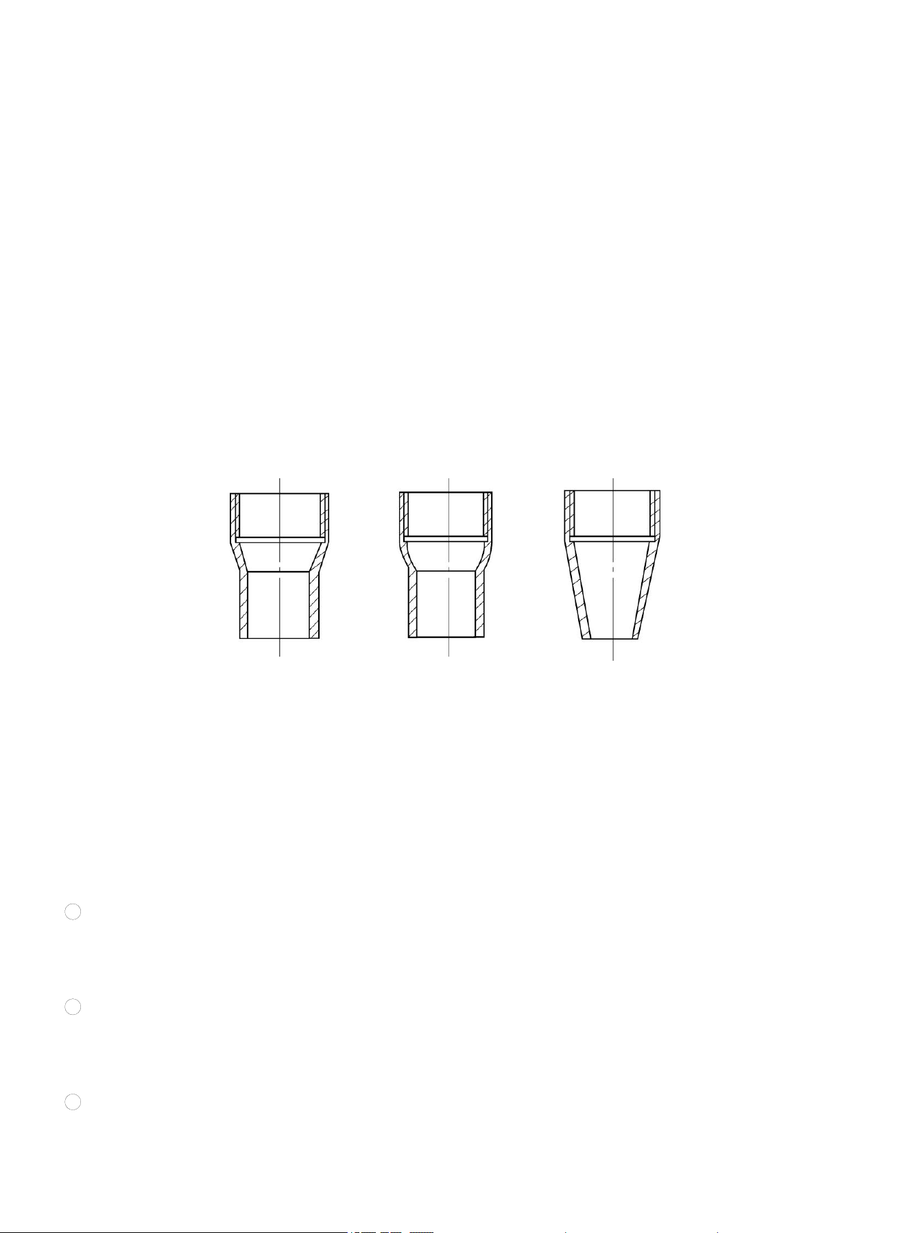
The welding gun nozzle serves as an important component that determines the gas shield protection
performance, and the common nozzle shapes are as shown in the figure. The cylindrical nozzle with conical or
spherical tail has the best protection effect, as the argon gas flow rate is uniform, which makes it easy to
maintain laminar flow. The conical nozzle has poorer protection effect because of the rapid argon airflow speed,
but it is easy to operate and has good visibility of molten pool, and is often used in welding.
Pic 13 Welding gun nozzle diagram
6.1.4 TIG Process
1) Cleaning before welding
Before carrying out TIG, the joint of the welded material and the welding wire must be cleaned to remove
the oxide film and oil stains on the metal surface to ensure the quality of the weld. The cleaning methods
include mechanical cleaning, chemical cleaning, and chemical mechanical cleaning.
1 Mechanical cleaning: This method is simple and effective. It is suitable for cleaning weldments with large
size and long welding cycle. Usually use a stainless steel wire brush and other tools with a small diameter for
polishing, or use a spatula to remove the surface oxide film to expose the metal luster of the welding part, and
then use an organic solvent to remove oil stains to clean the vicinity of the weldment joints.
2 Chemical cleaning: This method is often used for cleaning filler wire and small weldments. Compared with
the mechanical cleaning method, this method has the characteristics of high cleaning efficiency, stable and
uniform quality, and long retention time. The chemical solution and process used in the chemical cleaning
should be determined according to the material to be welded and welding requirements
3 Chemical mechanical cleaning: First use chemical cleaning, and then use mechanical cleaning at the
welding parts before welding. This combined cleaning method is suitable for weldments with higher quality
requirements.
(a) Cylinder mixed
with conical shape
(b) Cylinder mixed
with spherical shape
(c) Cone
https://www.arccaptain.com/

21
2)Gas protection effect
Argon is an ideal protective gas, with a boiling point of -186℃, between the boiling points of oxygen and helium.
It is a by-product of fractional distillation of liquid air in an oxygen plant to produce oxygen. In China, bottled
argon is used for welding, and its filling pressure is 15MPa at room temperature. The cylinder is painted gray
and marked with the word "Argon". The chemical composition requirements of pure argon are: Ar ≥ 99.99%;
He ≤ 0.01%; O2 ≤ 0.0015%; H2 ≤ 0.0005%; total carbon content ≤ 0.001%; moisture ≤ 30mg/m3.
It is beneficial to protect welding arc and reduce the consumption of protective gas during flat position welding.
Argon is a chemically inactive gas and does not chemically react with metals even at high temperatures, so
there is no oxidation and burning of alloying elements and a series of problems caused by it. Argon is also
insoluble in liquid metal, so it does not cause gas pores. Argon is a monatomic gas that exists in atomic state
and has no molecular decomposition or atomic endothermic phenomena at high temperatures. Argon has
small specific heat capacity and heat conduction capacity, that is, small heat absorption and less heat transfer.
Therefore, the heat in the arc is not easy to lose, making the welding arc combustion stable and the heat
concentrated, which are conducive to welding.
The disadvantage of argon is its high ionization potential. When the arc space is filled with argon, it is
difficult to ignite the arc, but the arc is very stable once ignited.
In the process of welding, the protection effect of argon is affected by many technological factors.
Therefore, it is necessary to pay attention to the effective protection of argon during TIG welding to prevent
interference and damage to the protection effect of argon; otherwise, it is difficult to obtain required welding
quality.
The welding technology factors affecting the argon protection effect include gas flow rate, nozzle shape and
diameter, distance between nozzle and weldment, welding speed, welding joint form, etc., which should be
considered comprehensively and selected correctly.
The quality of the argon protection effect is often evaluated by the welding spot test method by measuring
the range of effective argon protection zone. For example, use AC manual tungsten electrode TIG to conduct
spot welding on the aluminum plate, and the welding process conditions remain the same during welding; after
striking arc, hold the welding gun for 5-10s before turning off the power. At this time, a melting point will be left
on the aluminum plate. The "cathode crushing" around the welding spot will remove the oxide film on the
surface of the aluminum plate, and a grayish-white area with metallic luster will appear. This part where the
oxide film is removed is the effective argon protection zone, as shown in the figure. The larger the diameter of
the effective protection zone, the better the protection effect.
Effective protection zone
Melting zone
Oxidation zone
(a) Good protection effect (b) Bad protection effect
https://www.arccaptain.com/

22
Pic 14 Argon protection effect diagram
In addition, the argon protection effect can be evaluated by directly observing the color of the weld face.
Taking welding on stainless steels as an example, if the weld metal surface is silvery white or golden yellow, it
means that the protection effect is good; if the color is grey or black, it means that the protection effect is bad.
6.1.5 Welding Parameters
The gas protection effect, welding process stability and weld quality of TIG are directly related to welding
parameters. Therefore, reasonable selection of welding parameters is an important guarantee for obtaining
high-quality welded joints.
The welding parameters for TIG include: current type and polarity, tungsten electrode diameter, welding
current, argon flow, welding speed and process factors, etc.
① Current type and polarity: The current type and polarity of TIG should be selected according to the material
to be welded and the operation method.
② Tungsten electrode diameter: It is mainly selected according to the thickness of the weldment. In addition,
when the thickness of the material to be welded is equal, the allowable current of the tungsten electrode is
different due to the different types and polarities of the current used, so the diameter of the tungsten electrode
used is also different. If the diameter of the tungsten electrode is not selected properly, it will cause unstable
arc, severe burnout and tungsten inclusion in the weld.
③ Welding current: After the diameter of the tungsten electrode is selected, select the applicable welding
current. Too large or too small welding current will cause poor weld formation or welding defects.
④ Argon flow: It is mainly selected according to the tungsten electrode diameter and the nozzle diameter. For
nozzles with a certain aperture, the selected argon flow rate should be appropriate.
If the flow rate is too large, the gas flow rate will increase, and it will be difficult to maintain a stable laminar flow,
which is not good for the protection of the welding zone. Besides, it will take away a lot of heat from the arc
zone, which will affect the stable combustion of the arc. However, if the flow rate is too small, it is easy to be
interfered by the outside air flow, so as to reduce the argon protection effect. Usually the flow of argon is in the
range of 3-20L/min.
⑤ Welding speed: Under certain conditions of tungsten electrode diameter, welding current and argon gas
flow, too fast welding speed will cause the shielding gas flow to deviate from the tungsten electrode and the
molten pool, thereby affecting the argon protection effect. Moreover, the welding speed significantly affects the
shape of the weld. Therefore, an appropriate welding speed should be selected.
⑥ Process factors: Mainly include the shape and diameter of the nozzle, the distance from the nozzle to the
weldment, the length of the tungsten electrode, the diameter of the filler wire, etc. These process factors do not
change much, but they have different degrees of influence on the welding process and argon protection effect.
Therefore, they should be selected according to specific welding requirements.
Generally, the nozzle diameter can be selected within 5-20 mm; the distance from the nozzle to the weldment
shall not exceed 15 mm; the length of tungsten electrode out of the nozzle shall be 3-4 mm; and the diameter
of filler wire shall be selected according to the thickness of weldment.
6.1.6 General Requirements of TIG
1. Control requirements of gas: It is required that the gas is supplied first and exhausted last. Argon is an
inert-gas which is easy to be broken down. First fill argon between the workpiece and the electrode needle,
which is conducive to arc starting; after welding, keeping on supplying argon can prevent the workpiece from
https://www.arccaptain.com/
23
oxidation due to rapid cooling and ensure good welding effect.
2. Current manual switch control requirements: When the manual switch is pressed, the current is delayed
compared to the gas. After the manual switch is turned off (after the welding is completed), and the gas supply
current is cut off first according to the requirements.
3. High-voltage generation and control requirements: TIG adopts the high-voltage arc starting mode, which
requires to have high voltage when arcing, and no high voltage after arcing.
4. Interference protection requirements: High frequency is accompanied by high voltage of arcing in TIG, which
causes serious interference to the whole circuit and requires the circuit to have good anti-interference ability.
6.2 MMA Introduction
Warning! Do not disconnect the plug or cable in use during welding, otherwise
it will cause electric shock or damage to the machine!
The arc welding in which the welding electrode is manually operated is called manual electric arc welding, or
MMA for short. The MMA machine is simple, easy to operate, flexible and adaptable. It is suitable for welding of
various metal materials of various shapes and structures with a thickness of more than 2mm, especially for
weldments with complex structure shapes, short or curved welds and welds of different spatial positions.
6.3 MMA Welding
First, connect the output polarities of the welder with the weldment and the electrode holder respectively,
and then hold the electrode with the electrode holder. When welding, it will generate arc between the welding
electrode and weldment, and high-temperature arc will melt the electrode end and the weldment locally and
form a molten pool. The pool is then cooled and solidified rapidly to form a weld, so that the two separated
weldments are firmly connected as a whole. The covering of the electrode melts to form molten slag covering
the molten pool, and the slag cools to form a slag shell to protect the weld. Finally, the slag shell is removed,
and the welding of the joint is completed.
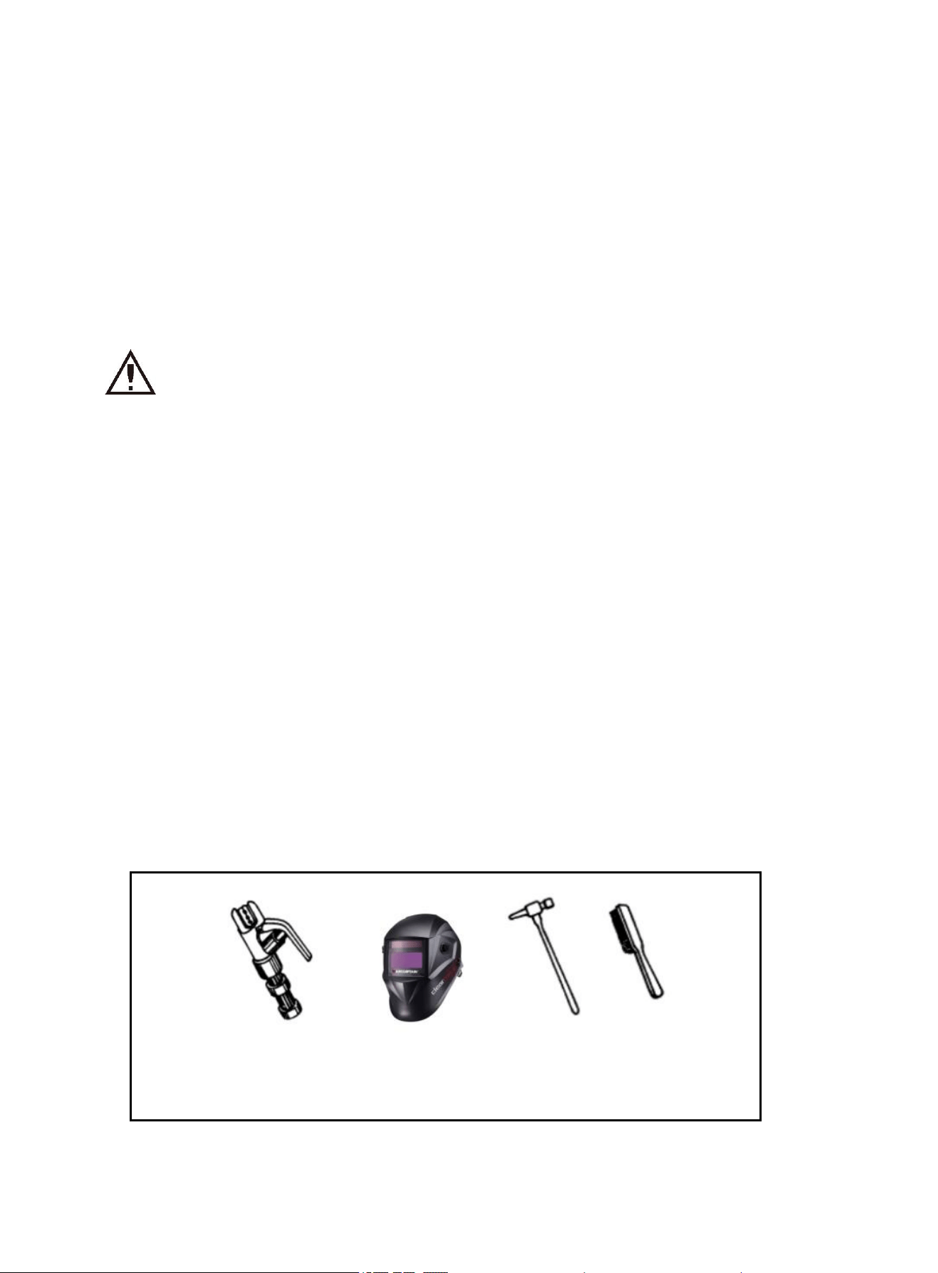
6.3.1 MMA Tools
The commonly used MMA tools include electrode holder, helmet, slag removal hammer and wire brush, etc.,
as well as welding cables and labor protection products.
a) electrode holder b) welding helmet c) slag hammer d) wire
brush
Pic 15 Common MMA tools
a) Electrode holder: It is a tool holding the electrode and conducting current. 300A and 500A are the most
https://www.arccaptain.com/
24
commonly used two types.
b) Helmet: It is a shielding tool that protects your eyes and face from arcs and metal spatters, including
hand-held and helmet-mounted types. The observation window of the helmet is equipped with colored
chemical glass, which can filter ultraviolet and infrared rays Therefore, the users can observe the arc burning
and molten pool through the observation window, which is convenient for operation.
c) Slag removal hammer (pointed hammer): It is a tool used to remove the slag shell on the weld face.
d) Wire brush: It is a tool used to remove the dirt and rust from weldment joints prior to welding, and weld face
and welding spatter after welding.
e) Welding cable: Multi-strand fine copper cable is often used. YHH type electric welding rubber sheathed
cable or THHR type electric welding rubber sheathed flexible cable can be used. A cable connecting the
electrode holder and the welder is called the welding cable (live wire). Another cable (earth lead) is used to
connect the welder and weldment. The outside of electrode holder is made of insulating material, which has
the function of insulation and heat insulation.
6.3.2 Basic MMA Operations
a. Cleaning of welding joint
Before welding, the joint should be removed from rust and oil, so as to facilitate arc initiation, arc stability and
ensure the quality of welds. When the rust removal requirements are not strict, wire brushes can be used;
when the requirements are strict, grinding wheels should be used.
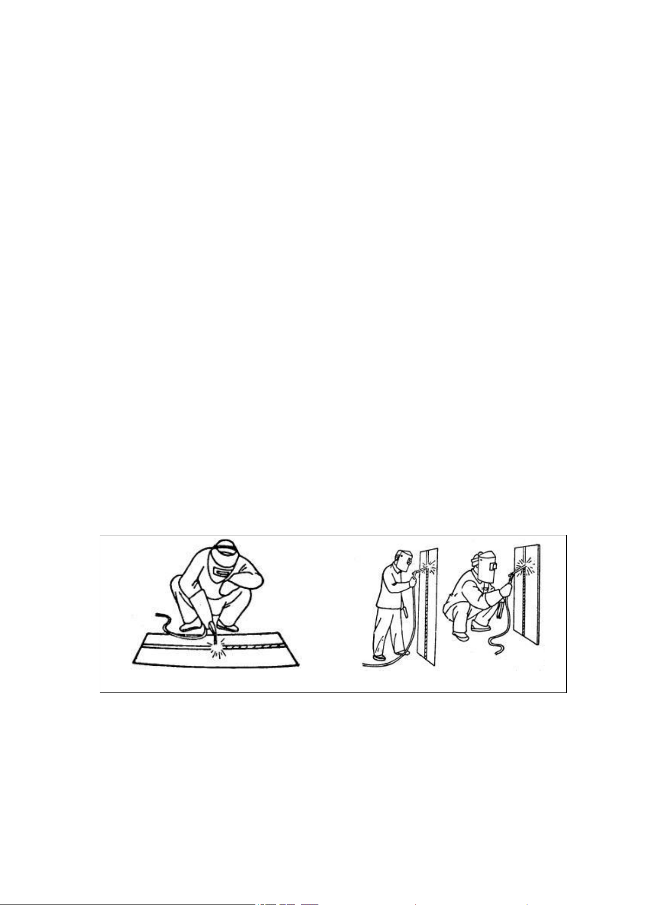
b. Operation posture
Take the flat position welding of butt joint and t-joint from left to right as an example, as shown in the figure.
The operator should stand on the right side of the weld's forward direction; hold the helmet in the left hand and
the electrode holder in the right hand; place the left elbow on the left knee to control the upper part of the body
not to follow downward movement; the forearm must be away from the ribs without support, and should be
stretched freely.
Flat position welding Vertical position welding
Pic 16 Welding posture
c. Striking arc
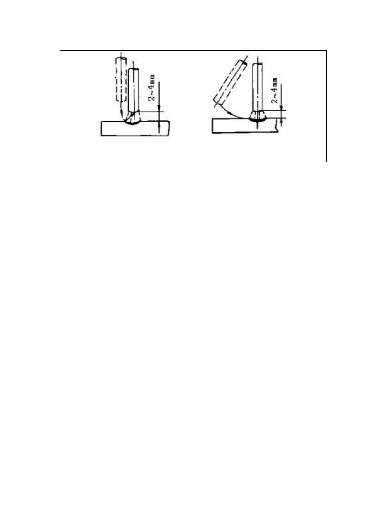
Striking arc is the process of generating a stable arc between the electrode and the weldment to heat the
electrode and the weldment for welding. There are two commonly used striking arc methods: scratch method
and hammering method, as shown in the figure. During welding, the end of the welding electrode contacts the
weldment face through scratching or hammering to form short circuit, and then lift the welding electrode quickly
for a distance of 2 to 4 mm, and the arc is ignited. If the welding electrode contacts the weldment face without
arcing, it is often that the end of the welding electrode has a covering that hinders the conduction. At this time,
https://www.arccaptain.com/
25
you can hit a few times to remove these insulators until the metal surface of the core wire is exposed.
Hammering method Scratching method
Pic 17 MMA striking arc method
d. Tacking
In order to fix the relative position of the two welds for welding, during welding assembly, short welds of
30 ~ 40mm are welded every certain distance so that the weldments are fixed in each other's position,
which is called tacking.
e. Electrode manipulation
The operation movement of electrode is called electrode manipulation. It is actually a combined
movement, that is, the electrode completes the movement in three directions simultaneously: the electrode
moves gradually along the welding direction; the electrode is gradually fed to the molten pool direction; the
electrode swings laterally, as shown in figure. After striking arc, manipulate the electrode in three directions
and put forward operation requirements for the most widely used butt welding to master the welding angle,
arc length and welding speed.
(1) Welding angle: As shown in the figure, the electrode shall be tilted forward 70-80º.
(2) Arc length: Generally, a reasonable arc length is approximately equal to the core diameter.
(3) Welding speed: The proper welding speed should make the weld width of the welding bead
approximately equal to twice the core diameter, with a smooth surface and fine ripples. When the welding
speed is too high, the welding bead is narrow and high, the ripple is rough, and the fusion is bad. When the
welding speed is too low, the weld width is too large and the weldment is easy to burn through. Also note
that the current should be appropriate, the welding electrode must be aligned, the arc must be low, the
welding speed must be even rather than too fast.
https://www.arccaptain.com/
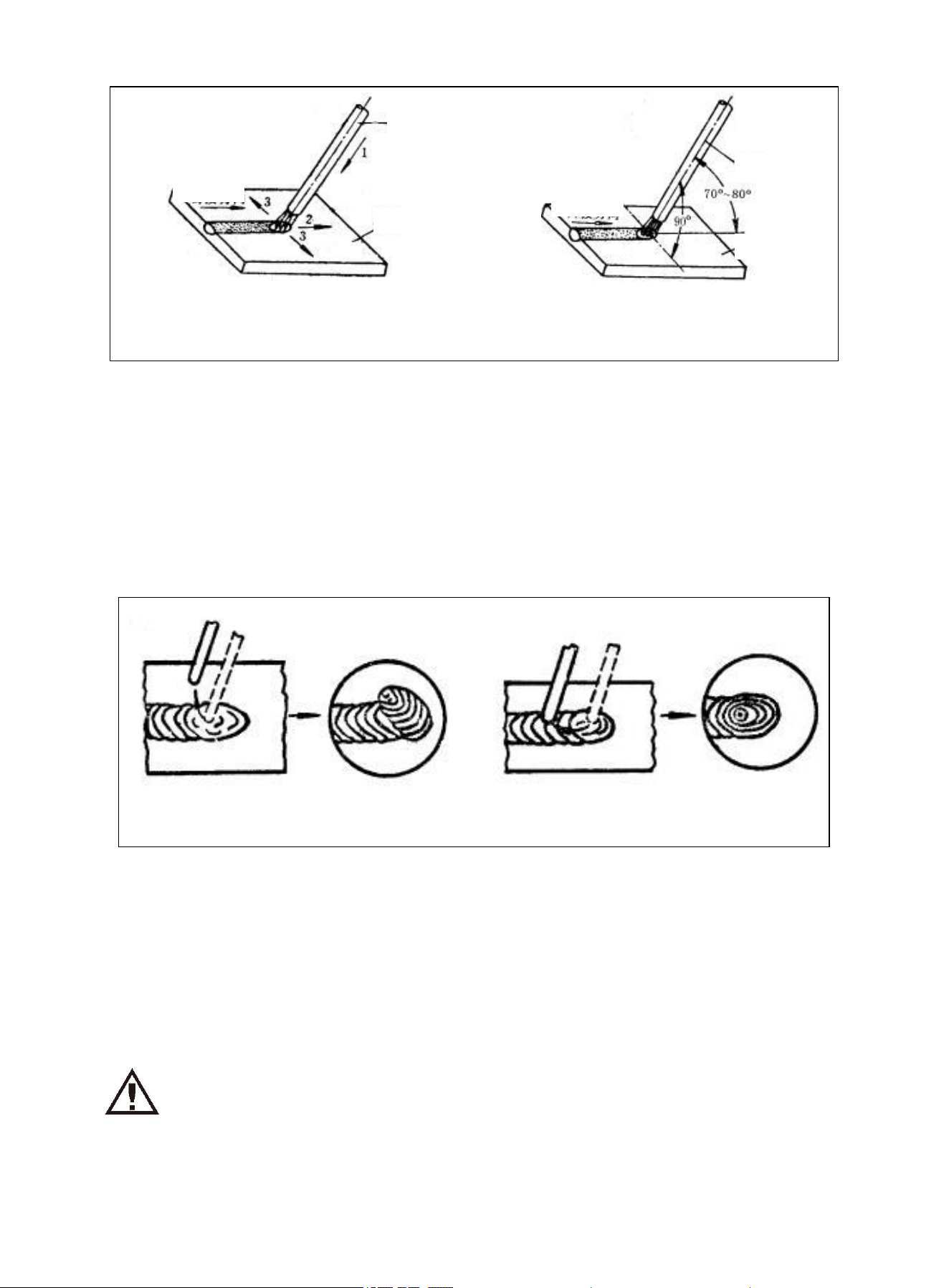
26
1. Feed down 2. Move along the welding
direction 3. Swing laterally
Welding electrode angle in flat position welding
Pic 18 MMA electrode manipulation diagram
f. Quenching of arc
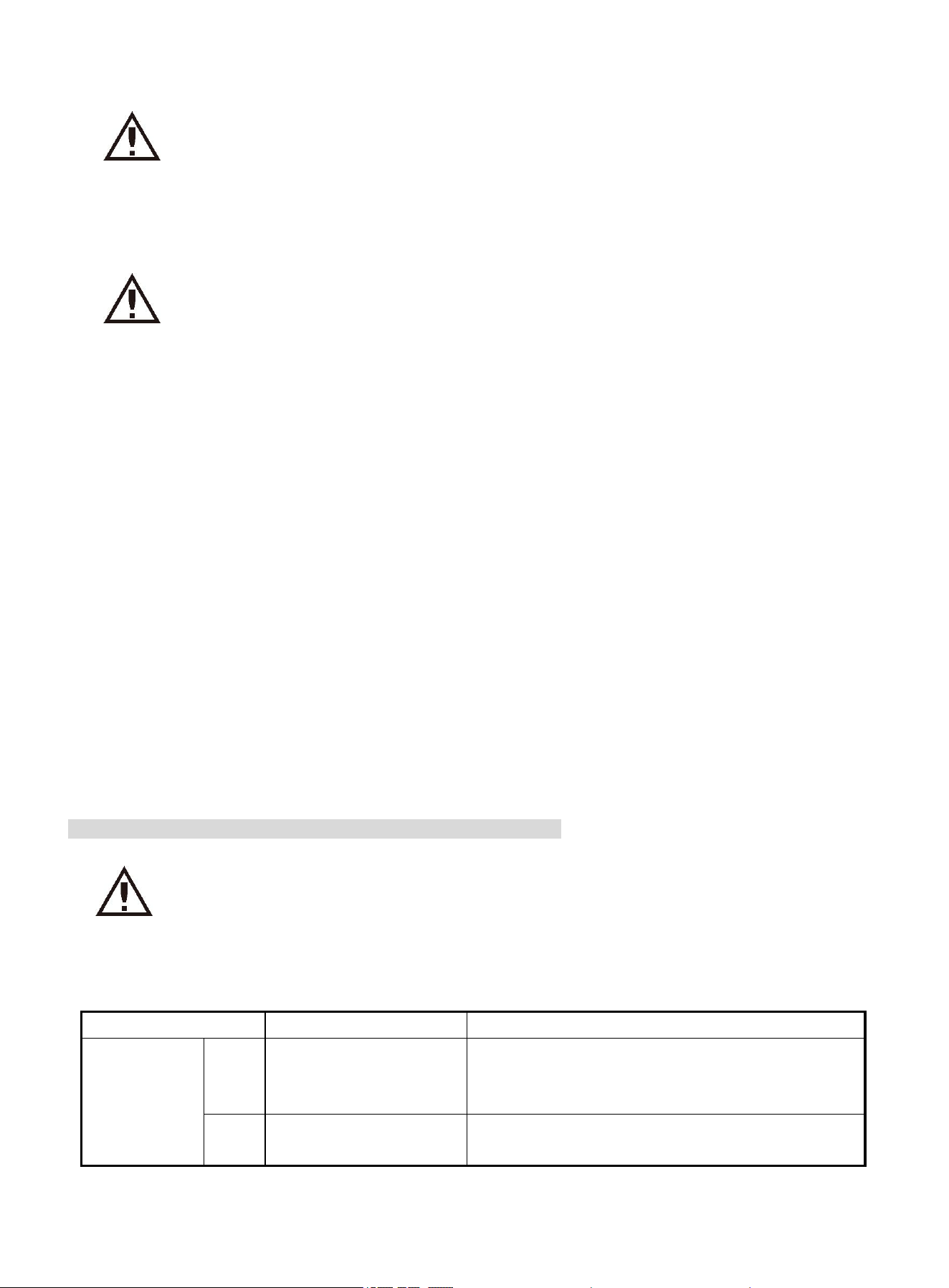
During welding, quenching of arc is inevitable. If the quenching of arc is poor, it will form a very shallow molten
pool, and the density and strength of the weld metal are poor, so it is easy to form such defects as cracks,
pores and slag inclusion. When the arc is quenching, gradually pull up the end of the electrode to the groove,
and raise the arc to narrow the molten pool and reduce the amount of metal and heat, so that quenching of arc
does not cause defects such as cracks and pores; besides, pile up the weld metal of the crater to smoothly
pass the molten pool. After welding, file or shovel off the excess part. The arc quenching operation method is
shown in the figure.
Quenching of arc outside the bead Quenching of arc on the bead
Pic 19 MMA arc quenching diagram
g. Cleaning of weldment
After welding, use wire brush and other tools to clean up solidified slag and spatter.
7. Precautions & Maintenance
7.1 Precautions
Warning! Dropping may cause machine damage or personal injury. Please
operate in accordance with the transportation and placement labels on the
machine, and use a cart or similar tools with corresponding load-bearing
capacity for transportation.
1. Welder lifting method: The welder can be lifted by fork lift or crane. As the welder is not equipped with
lifting rings, special attention should be paid to fixing method when using crane for lifting.
Electrode
Electrode
Weldment
Weldment
Welding
direction
Welding
direction
https://www.arccaptain.com/

27
2. Input cable specification: Adopt 3×2.5 mm 2 cable to connect the power distribution box and welder, and
the power distribution box must be equipped with breaker or fuse of no less than 60A.
3. Protective earth lead connection: Be sure to connect the yellow-green wire in input cable of the welder to
the protective ground of the welding place.
4. Welder cooling type: The welder adopts air cooling, and the air inlet and outlet of the welder cannot be
blocked when using to ensure smooth ventilation.
5. Protection class of the welder: IP21S.
6. Duty cycle of the welder: The duty cycle of MMA is 30%, and of TIG is 25%. The welder has the overheat
protection function, which will automatically cut off the output in case of overheat protection.
7. Inclination of welding power source: The inclination should not exceed 15°, otherwise it is easy to tip.
8. Using environment of welder: It should meet the following requirements:
a. Ambient air temperature range: -10℃~+40℃ during welding, and -25℃~+55℃ during transportation and
storage
Note: When using a water cooler, pay attention to prevent it from being used or stored at the solidification
temperature of the coolant; when storing at a low temperature, the coolant should be drained first!
b. Relative air humidity: no more than 50% at 40°C, no more than 90% at 20°C
c. The dust, acid, corrosive gas or substances in the surrounding air shall not exceed the normal content,
except for these substances produced in the welding process.
9. Do not use welding power source for thawing of pipes.
10. Do not put hands, hair, tools, etc. near the live devices in the machine when it is energized, such as fans,
so as to avoid personal injury or damage to the machine.
11. Avoid water or water vapor from entering the inside of the welder. If such condition occurs, the inside of the
welder should be dried. Then, the insulation of the welder (including between the connection nodes and
between the connection points and the enclosure. shall be measured with a megohmmeter. Only when it is
confirmed that there is no abnormal situation can the welding work be continued.
12. The welder and welding gun can only be operated according to their duty cycle.
13. Use proper welding cable: When the cable is thin, the current is insufficient, the arc stability is poor, the
rated output power cannot be obtained, and the cable is easily burned.
14. Correct connection is the premise to ensure good welding effect. Do not connect the positive and negative
output ends of the welder inversely.
15. Use water-cooled welding gun: To prevent the welding gun from burning out, cooling water with a water
pressure of 1-2kg/cm
2
is required. Even when the water-cooled welding gun is used under low current, the
water must be cooled; otherwise, the gun cannot be used.
16. Unobstructed air hose and water hose: When a heavy object is placed on the air hose or water hose or the
hose is bent, the flow of gas and water may stop, which can cause the welding gun to burn out and cause weld
defects.
17. Protect welding gun: rough operation of welding gun is easy to cause wire breakage, water leakage (air
leakage., and nozzle damage.
18. Poor flow meter or gas hose connection will lead to gas leakage or reduced gas flow at the front of the
nozzle, so the gas protection effect will be reduced, and the weld gas pores are prone to appear. Please use
soapy water to check for gas leakage.
19. Reliable connection: The connection between the welder and power supply, welding gun, electrode holder,
or earth lead as well as various control cables shall be reliable. If the connection is improper and the contact is
poor, it will cause malfunction, resulting in abnormal welder status, or burnout, etc.
20. Connection with weldment: If someone uses the steel plate and rebar to replace the cable of weldment, it
will cause large resistance and unstable welding current. Besides, overheating may lead to fire. Therefore,
please connect the base metal with regular insulated cables reliably.
21. There should be windproof measures in windy workplaces, otherwise it will blow away the protective gas
and form gas pores.
22. Clean the oil, rust, paint, water and other conductive substances attaching on the base metal surface to be
welded; otherwise, it will become pores and cracks, and cannot obtain good welding effect.
https://www.arccaptain.com/
28
Warning! The machine is provided with overcurrent and overheat protection
circuit. When the grid voltage, output current or internal temperature exceed
the limit, the machine will stop operation automatically. In addition, high input
grid voltage will cause welder damage.
7.2 Maintenance
Warning! All operations can only be carried out with the welder power source being
turned off. Check and confirm that the input cable of the welder is disconnected from
the power system before open the machine cover.
1. Regularly clean the dust inside the power source: Excessive dust inside the power source will reduce the
insulation performance of the welder, which directly threatens the safety of the human body and the welder.
The power source must be cleaned at least twice a year. If the welder is used in an environment with serious
smoke and air pollution, the welder should be dusted daily. Before cleaning, turn off the power switch first,
remove the side and top covers, and blow off the dust with dry compressed air from top down. The pressure of
compressed air shall be at a reasonable level so as not to damage the small components in the welder. Wipe
with a cloth if it is attached with grease.
2. Regularly check the internal circuit connection of the welder, make sure that the circuit connection is correct
and the connector is firm (especially the inserted connector or component. If rust and looseness are found,
grind off the rust layer or oxide film with sand paper, reconnect and tighten it.
3. Periodically check whether the insulating skin of all cables of the welder is damaged, and wrap it or replace
the cable.
4. Regularly check the insulation resistance of welder: Mainly check the insulation resistance between the
power input and output of the welder, and the power input and the enclosure, which should be greater than 10
megohm.
5. If the welder is not used for a long time, the welder shall be put back in the original packing box and stored in
a dry environment.
8. Troubleshooting
Warning! The following operations can only be carried out by operators with sufficient
electrical expertise and comprehensive safety knowledge, and with valid qualification
documents to demonstrate their ability and expertise. Check and confirm that the input
cable of the welder is disconnected from the power system before open the machine cover.
8.1 Common Malfunction Analysis and Solution
Symptom Reasons Measures taken by users
The LED
display shows
"EXX"
E30
· Power input phase
loss;
· Check if the power cord is connected well. If the
problem still exists, please contact the after-sales
department of the company.
E60 · Overheat protection
· It will automatically recover after the welder is
cooled
https://www.arccaptain.com/

29
8.2 TIG Problems and Elimination
Symptom Analysis Corrective Action
The panel has no
display after startup
The power cord is not
connected properly
The welder fails
· Check again and connect the power cord properly
· Contact the customer-service personnel of the
company and seek professional help
No arc is started in
MMA mode
· The welding circuit is
abnormal
· The output port of the
welder has no output
voltage
· Check whether the earth clamp and electrode
holder are properly connected
· Contact the customer-service personnel of the
company and seek professional help
The arc is difficult
to start in MMA
mode
· The hot start parameter is
set too small
· Reset the hot start parameter
Arc is easily
interrupted in MMA
mode
· The mains voltage is too
low
· Use after the mains voltage is normal
No arc is started
after pressing the
gun in TIG mode
· The welding gun does not
release the high frequency
· The welding circuit is
abnormal
· Start the arc again after replacing the welding gun
· Check whether the earth clamp and welding gun
are connected well
The tungsten
needle burns out in
TIG mode
· The welding gun polarity
is connected wrongly
· The AC balance is too
large
· Connect the welding gun to the negative polarity
of the machine
· Reduce the AC balance appropriately
The TIG arc is
unstable
· The tungsten needle
clamp of the welding gun
deforms and the gas flow is
unstable
· The gas hose of welding
gun is abnormal
· Replace the tungsten needle clamp of the TIG
welding gun
· Sort out the welding gun circuit to avoid blockage
and squeeze of the gas hose
The weld is not
bright
· The tungsten needle
clamp of the welding gun
deforms and the gas flow is
unstable
· The gas hose of welding
gun is abnormal
· There are impurities on
the workpiece surface
· Replace the tungsten needle clamp of the TIG
welding gun
· Sort out the welding gun circuit to avoid blockage
and squeeze of the gas hose
· Clean the surface impurities of workpiece
The tungsten
needle becomes
black after
quenching of arc
· The tungsten needle is
burnt out
· Delay the post-flow time
https://www.arccaptain.com/
30
Note: The phenomena listed here may be related to the accessories you use, gas, environmental factors and
power supply. Please try to improve the environment and avoid such situations.
Warning! Inexperienced or careless maintenance can lead to greater failure of
the machine, making formal inspection and maintenance more difficult. After
the welder is energized, there will be life-threatening voltage in the exposed
parts of the welder. Any direct or indirect contact will cause electric shock, and
serious electric shock can even be fatal.
8.3 Welding Procedure Checklist (for reference only.
The selection of welding current and arc voltage directly affects the stability, welding quality and
productivity of the welding process. To guarantee welding quality, it is required that the welding current and arc
voltage match each other well. They are usually selected according to the diameter of the used, the required
form of metal transfer and the requirements of productivity.
8.4 SMAW Process Parameters
Welding
line space
position
Weldment
thickness or
leg dimension
Weld in gline of layer
Welding line of other
layers
Back sealing welding
line
Core
diameter
Welding
current/A
Core
diameter
Welding
current/A
Core
diameter
Welding
current/A
mm inch mm inch mm inch mm inch
Flat butt
weld
2 0.08 2 0.08 55~60 ~ ~ ~ 2 0.08 55~60
2.5~3.5 0.1-0.14 3.2 0.12 90~120 ~ ~ ~ 3.2 0.12 90~120
4~5 0.16-0.2
3.2 0.12 100~130
~ ~ ~
3.2 0.12 100~130
4 0.16 160~200 4 0.16 160~210
5 0.2 200~260 5 0.2 220~250
5~6 0.2-0.24 4 0.16 160~210
~ ~ 3.2 0.12 100~130
4 0.16 180~210
≥6 ≥0.24 4 0.16 160~210
4 0.16 160~210 4 0.16 180~210
5 0.2 220~280 5 0.2 220~260
0.12
0.47
4 0.16 160~210
4 0.16 160~210 ~ ~ ~
5 0.2 220~280 ~ ~ ~
Vertical
butt weld
2 0.08 2 0.08 50~55 ~ ~ 2 0.08 50~55
2.5~4 0.1-0.16 3.2 0.12 80~110 ~ ~ 3.2 0.12 80~110
5~6 0.2-0.24 3.2 0.12 90~120 ~ ~ 3.2 0.12 90~120
7~10 0.28-0.4
3.2 0.12 90~120
4 0.16 120~160 3.2 0.12 90~120
4 0.16 120~160
≥11
≥0.43
3.2 0.12 90~120 4 0.16 120~160
3.2 0.12 90~120
4 0.16 120~160 5 0.2 160~200
12~18
0.48-0.71
3.2 0.12 90~120
4 0.16 120~160 ~ ~ ~
4 0.16 120~160
≥19 ≥0.75 3.2 0.12 90~120 4 0.16 120~160 ~ ~ ~
https://www.arccaptain.com/
31
4 0.16 120~160 5 0.2 160~200
Horizontal
butt weld
2 0.08 2 0.08 50~55 ~ ~ ~ 2 0.08 50~55
2.5 0.1 3.2 0.12 80~110 ~ ~ ~ 3.2 0.12 80~110
3~4 0.12-0.16
3.2 0.12 90~120 ~ ~ ~ 3.2 0.12 90~120
4 0.16 120~160 ~ ~ ~ 4 0.16 120~160
5~8 0.2-0.31 3.2 0.12 90~120
3.2 0.12 90~120 3.2 0.12 90~120
4 0.16 140~160 4 0.16 120~160
≥9 ≥0.36
3.2 0.12 90~120
4 0.16 140~160
3.2 0.12 90~120
4 0.16 140~160 4 0.16 120~160
14~18 0.55-0.71
3.2 0.12 90~120
4 0.16 140~160 ~
4 0.16 140~130
≥19 ≥0.75 4 0.16 140~160 4 0.16 140~160 ~
Overhead
butt weld
2 0.08 ~ ~ ~ ~ ~ ~ 2 0.08 50-65
2.5 0.1 ~ ~ ~ ~ ~ ~ 3.2 0.12 80-110
3~5 0.12-0.2 ~ ~ ~ ~ ~ ~
3.2 0.12 90-110
4 0.16 120-100
5~8 0.2-0.31 3.2 0.12 90-120
3.2 0.12 90~120 ~ ~ ~
4 0.16 140~160
≥9 ≥0.36
3.2 0.12 90-120
4 0.16 140~160 ~ ~
4 0.16 140-160
12~18
0.48-0.71
3.2 0.12 90-120
4 0.16 140~160 ~ ~
4 0.16 140-160
≥19 ≥0.75 4 0.16 140-160 4 0.16 140~160
Fillet weld
in the
horizontal
position
2 0.08 2 0.08 55-65 ~ ~ ~
3 0.12 3.2 0.12 100~120 ~ ~ ~
4 0.16
3.2 0.12 100~120 ~ ~ ~
4 0.16 160~200 ~ ~ ~
5~6 0.2-0.24
4 0.16 160~200 ~ ~ ~
5 0.2 220~280 ~ ~ ~
≥7
≥0.28
4 0.16 160~200
5 0.2 220~230
5 0.2 220~280
~ ~ 4 0.16 160~200
4 0.16 160~200
4 0.16 160~220
5 0.2 220~280
Fillet weld
in th
evertical
position
2 0.08 2 0.08 50~60 ~ ~ ~
3~4 0.12-0.16 3.2 0.12 90~120 ~ ~ ~
5~8 0.2-0.31
3.2 0.12 90~120 ~ ~ ~
4 0.16 120~160
9~12
0.36-0.48
3.2 0.12 90~120
4 0.16 120~160
4 0.16 12~0160
~ ~
3.2 0.12 90~120
4 0.16 120~160 3.2 0.12 90~120
4 0.16 120~160
Fillet weld 2 0.08 2 0.08 50~60 ~ ~ ~
https://www.arccaptain.com/
32
in the
overhead
position
3~4 0.12-0.16 3.2 0.12 90~120 ~ ~ ~
5~6 0.2-0.24 4 0.16 120~160 ~ ~ ~
≥7
≥0.28
4 0.16 140~160 4 0.16 140~160
~ ~
3.2 0.12 90~120
4 0.16 140~160
3.2 0.12 90~120
4 0.16 140~160 4 0.16 140~160
Current range of thorium (cerium) tungsten electrode of various diameters
Tungsten diameter DC positive polarity DC negative polarity AC
mm inch A A A
1 0.04 15~80 — 20~60
1.6 0.06 70~150 10~20 60~120
2.4 0.09 150~250 15~30 100~180
3.2 0.12 250~400 25~40 160~250
4 0.16 400~500 40~55 200~320
When the welding conditions do not meet the requirements, the phenomenon described in the following table
will occur.
Common welding problems
Unsuitable
Welding
Conditions
Influence
Unsuitable Welding
Conditions
Influence
The welding
gun is far
away from the
workpiece
The arc becomes long
The welding gun is
too close to the
workpiece
The arc becomes shorter
The welding bead becomes narrow Welding spatter will occur
The gas protection effect is reduced
The welding
current is too
large
The welding bead becomes narrow
The welding speed is
too fast
The bead becomes short
The depth of penetration and excess
weld metal becomes greater
The depth of penetration
and excess weld metal
becomes smaller
https://www.arccaptain.com/