Inverter Welding Machine
TIG200
User Manual
www.arccaptain.com


Dear Valued Customer,
Thank you very much for being our valued customer. ARCCAPTAIN welder was built by
high quality components, every single unit machine was passed multiple industry leading
laboratory tests to provide a great welding experience and performance.
For your safety, please read and understand this manual carefully before using this
product. Your satisfaction is our priority! For any question or concerns, please do not
hesitate to contact ARCCAPTAIN for SUPPORT :
www.arccaptain.com
https://www.arccaptain.com/

CONTENTS
1. SAFETY GUIDANCE..............................................................................................1
1.1 Precautions for Operations and Installation
.....................................................................
1
1.2 Preparation before welding................................................................................................ 3
1.3 Precautions for discard
.......................................................................................................
4
2. PRODUCT DESCRIPTION....................................................................................4
2.1 Function and Features
........................................................................................................
4
2.2 Technical Parameters.......................................................................................................... 5
2.3 Dimension and weight
.........................................................................................................
5
2.4 Composition and Picture of the welding machine system............................................. 6
2.5 System characteristics
........................................................................................................
7
3. FUNCTION............................................................................................................... 8
3.1 Panel of TIG200
...................................................................................................................
8
3.2 Panel functions of TIG200.................................................................................................. 8
4. INSTALLATION AND CONNECTION
.................................................................
9
4.1 Installation requirements.....................................................................................................9
4.2 Electrical connection
..........................................................................................................
11
4.3 Installation and Commission............................................................................................ 11
4.4 Strap Installation
................................................................................................................
15
5. WELDING PARAMETERS TABLE................................................................... 16
6. MAINTENANCE
....................................................................................................
18
7. FAILURE DIAGNOSIS AND TROUBLESHOOTING.....................................21
https://www.arccaptain.com/
1
1. SAFETY GUIDANCE
1.1 Precautions for Operations and Installation
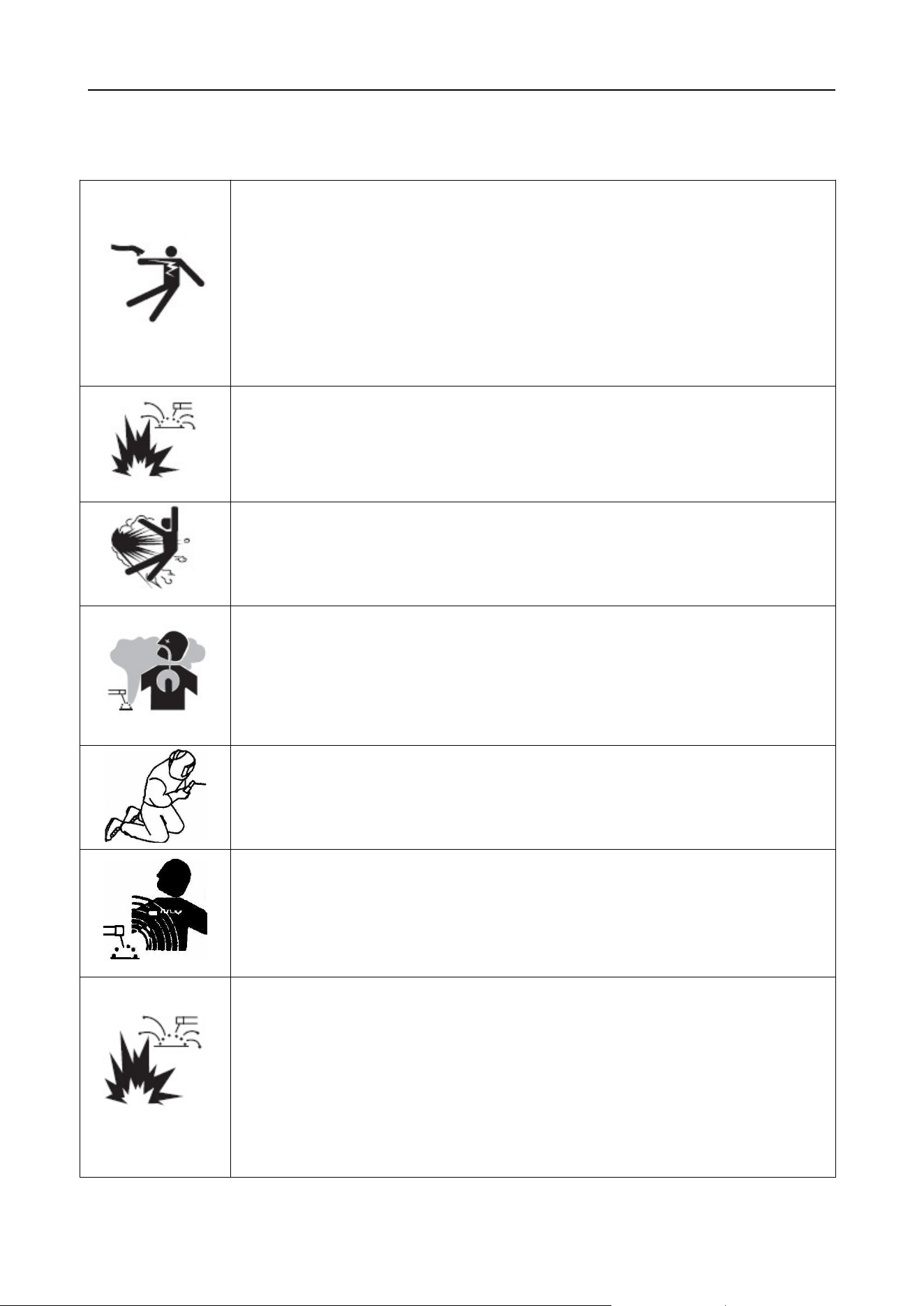
Beware of electric shock!
Install grounding devices according to application standard.
Do not touch live parts with naked skin, wet gloves or wet clothes.
Be sure you are insulated from ground and workpiece.
Cover the cover plate of the machine before power on to avoid an electric
shock.
Confirm the safety of your working position.
Beware of fire hazard!
To avoid fire hazard, please install the machine on non-combustible
materials;
To avoid fire hazard, please make sure there are no inflammables nearby.
Beware of explosion!
To avoid explosion, please do not install the machine in an explosive gas
environment.
Smoke-may be harmful to your health!
Keep your head away from the smoke to avoid inhalation of waste gas in
welding.
Keep the working environment well ventilated with exhaust or ventilation
equipment when welding.
Arc radiation-may hurt your eyes and burn your skin!
Use proper mask and wear protective clothing to protect your eyes and body.
Use proper mask or curtain to protect onlooker from being injured.
Magnetic field can make cardiac pacemaker a bit wonky.
People with cardiac pacemaker should consult the doctor before carrying out
welding.
Stay away from the power source to reduce the affect of magnetic filed.
Improper use and operation may result in a fire or an explosion.
Welding spark may result in a fire, so please make ensure there are no
inflammables near the welding position, and pay attention to fire safety.
Ensure there is fire extinguisher nearby, and make sure someone has been
trained to operate the fire extinguisher.
Do not weld closed container.
Do not use this machine for pipe thawing.
https://www.arccaptain.com/
2
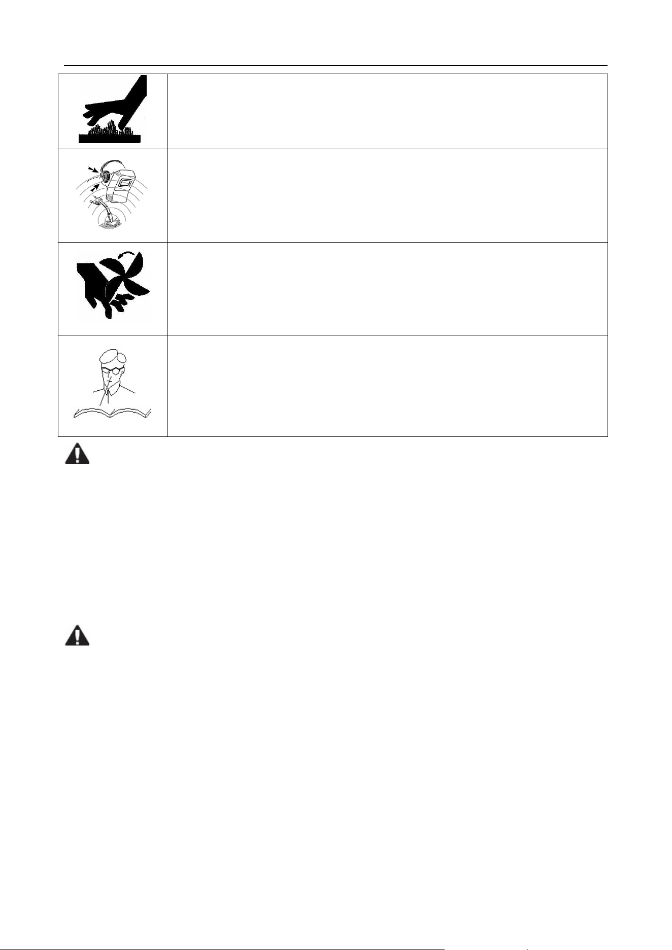
Hot workpiece can cause severe scald.
Do not touch hot workpiece with bare hands.
Cool the welding torch for a while after continuously working.
Excessive noise can be harmful to hearing.
Wear ear covers or other hearing protectors when welding.
Give warning to nearby personnel that noise may be potentially hazardous to
hearing.
Moving parts may injure your body.
Please keep away from moving parts (such as fan).
All doors, panel, cover, baffle plate, and other protective device should be closed
and well located.
Asking for professional support while trouble strikes.
When trouble strikes in installation and operation, please resort to this
manual for according contents.
If you are still in lost, or you still cannot solve the problem, please contact the
dealer or the service center for professional support.
Moving the machine can be dangerous.
Please make sure the input power switch is turned off before moving the machine.
Do not stress the operation panel and cover plate while moving the machine so that to avoid falling
items hurting others.
Please fix the wheels tightly while moving the machine with a forklift.
To avoid possible fire hazard or other damages, please do not install and operate this machine if it’s
found damaged or lack of components.
Replacing machine components can be dangerous.
Only qualified personnel can replace the machine components. Make sure there are no foreign
bodies such as wire leads, screws, gaskets and metal bars falling into the machine when replacing
the components.
Make sure the connecting wires inside the machine are correctly connected after replacing the
PCBs, and then the machine can be run. Otherwise, there is a risk of damage to property.
https://www.arccaptain.com/

3
Other Precautions
1) Make sure the place to install the machine can bear the weight of welding machine.
2) Do not install the machine at places where water droplet splash may occur, such as near water
pipes.
3) Welding should be carried out in dry environment with humidity less than 90%.
4) Avoid welding in the open air unless sheltered from sunlight and rain. Keep it dry and do not place it
on wet ground or in puddles.
5) Do not carry out welding with the welding machine placed on a platform with a pitch greater than 10°.
This product is equipped with over current/over voltage/overheating protection circuit. When the mains
voltage, output current or inner temperature exceeds the set standard, the machine will stop
automatically. However, excessive use of machine may also damage the machine; therefore, please pay
attention to the following:
Good ventilation
A working welder will generate big current and has strict cooling requirements that cannot be met
with natural ventilation. Therefore the built-in fan is very important in enabling the machine to work
stable with effective cooling. Operator should make sure that the louvers be uncovered and
unblocked.
Over voltage is forbidden.
This machine is of automatic mains voltage compensation, which ensures that the welding current
varies within the given range. In case that the input mains voltage exceeds the tolerance value, it
would possibly damage the machine; therefore, operators should understand take relevant
precautions in advance.
Overload is forbidden.
Please observe the max load current at any moment (refer to the corresponding duty cycle). Make
sure that welding current not exceeding the maximum load current. Overload could obviously
shorten the machine's lifespan, or even damage the machine.
Suddenly the “E61” code may appear on the digital screen while the machine is of over-load status.
Under this circumstance, it is unnecessary to restart the machine. Keep the built-in fan working to
lower the temperature inside the machine. Welding can be continued after the inner temperature falls
into the standard range and the “E61” code is disappeared.
1.2 Preparation before welding
1)
Safety devices
To avoid gas poisoning, suffocation, dust poisoning, please use air discharge equipment as
required and wear respiratory protection devices.
Please wear safety goggles or other protection devices which are of sufficient shading when
welding or guiding welding.
https://www.arccaptain.com/

4
To avoid eyes being hurt by spatters, please wear protective goggles.
Please wear welding specialized protective clothing, such as leather protective gloves, long-sleeved
clothes, welding spats, aprons, etc.
Please install protective barrier to protect standbys from hurting by arc light.
Please wear sound insulation devices when noise is too huge.
Please use ventilator for air exchanging; please take anti-wind measures so that to avoid poor
welding performances resulted from direct blowing to arc.
2) Cable connection check
Fix welder—place welders on dry, flat position which is of good ventilation.
Please make sure the correct and tight connection of grounding cable, power input cable, welding cable
and workpiece side cable.
3) Other items’ check
Please check the shielding gas, welding environment, welding torch and make sure they are all in good
condition.
1.3 Precautions for discard
Pay attention to the following when discarding welding machine:
Burning the electrolytic capacitors in the main circuit or on the PCBs may cause an explosion.
Burning the plastic parts such as the front panel may produce poisonous gas.
Dispose it as industrial waste.
2. PRODUCT DESCRIPTION
2.1 Function and Features
TIG welder is of constant current external characteristic. Welding current will not be changed per arc
length but being kept at a very stable level. It adopts PWM technology and high-power switching
element IGBT (discrete) to rectify AC110V/AC220V (50Hz/60Hz) voltage to DC310V, after inverting
it to 45KHz, there is a voltage step-down and rectification again, stable welder current is obtained by
output current feedback and adjustment.
Built-in MCU technology and IGBT inverter Welder, totally digital control, which ensures great and
stable welding performance.
TIG200 is TIG and MMA 2 in 1 Multi-Process welding machine.
MMA/Stick welding features: hot start, arc force and an-stick.
TIG welding features: 2T/4T Operation, current regulation, post-flow adjustable, down-slope.
Fan-On-Demand power source cooling system operates only when needed, reducing noise, energy
use and the amount of contaminants pulled through the machine.
Portable and Lightweight: 11.68lb, carry with handle or shoulder strap.
https://www.arccaptain.com/
5
Safety protection: over current/over voltage/overheating protection circuit.
Unique Design & LED Display Panel, read data more clear, concise distribution and convenient
operation. Warning indicator for normal working and abnormal working.
Remote control function available: support foot pedal & analog torch (purchase additional if need).
2.2 Technical Parameters
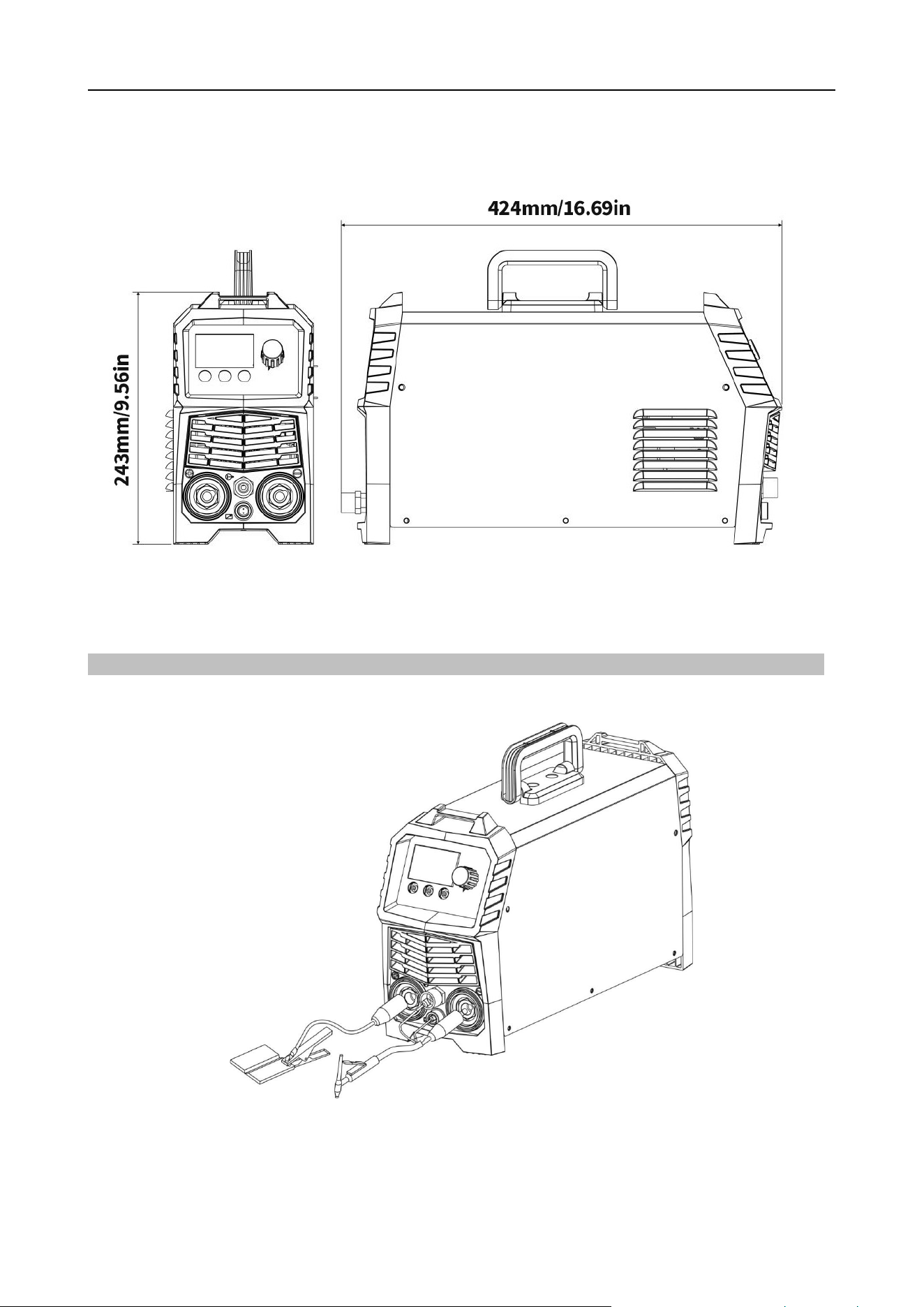
2.3 Dimension and weight
Model TIG200
Dimension(L*W*H) 424*135*243mm/16.69*5.3*9.56in
Weight 5.3kg/11.68lb
Items TIG200
Rated Input Power Single Phase AC220V/AC110V ±15% 50Hz/60Hz
Rated Input Capacity
(
kVA
)
7.8
Rated Input Current
(
A
)
TIG:28 MMA:35
Rated Output
Current/Voltage
(
A/V
)
TIG:200A/18V
MMA:170A/26.8V
@220V
TIG:140A/15.6V
MMA:120A/24.8V
@110V
Rated Duty Circle 40%
No-load voltage (V) DC 62
Output Current Range
(
A
)
TIG:10-200
MMA:10-170
@220V
TIG:10-140
MMA:10-120
@110V
Post-flow Time
(
s
)
0--10
Down slope(s) 0--10
Arc Ignition Type HF
Enclosure Protection Class IP21S
Insulation Grade H
Power Factor
0.73
Efficiency (%)
80
https://www.arccaptain.com/
6
Pic 1 Welder Appearance and Dimension
(
Unit
:
mm/in
)
2.4 Composition and Picture of the welding machine system
1) Welding system composition
Pic 2 Welding System Composition
https://www.arccaptain.com/
7
2) Ordering and Packing List
Name Specification Quantity (pcs)
TIG welder TIG200 1
TIG torch & accessories WP-17 (13ft/4m) 1
Electrode Holder
200A-16mm
2
(
9ft/ 3m
)
DKJ 35-50
1
Earth clamp
300A-16mm
2
(
9ft/ 3m
)
DKJ 35-50
1
Operator’s manual Operator’s manual of TIG200 1
Gas hose Gas hose with gas connector 1
Conversion adapter American adapter plug 1
Strap 0.1*4.3ft (30mm*1500mm), Black 1
Tungsten electrode
φ
1/16”, 6”
(
1.6mm, 150mm)
1
2.5 System characteristics
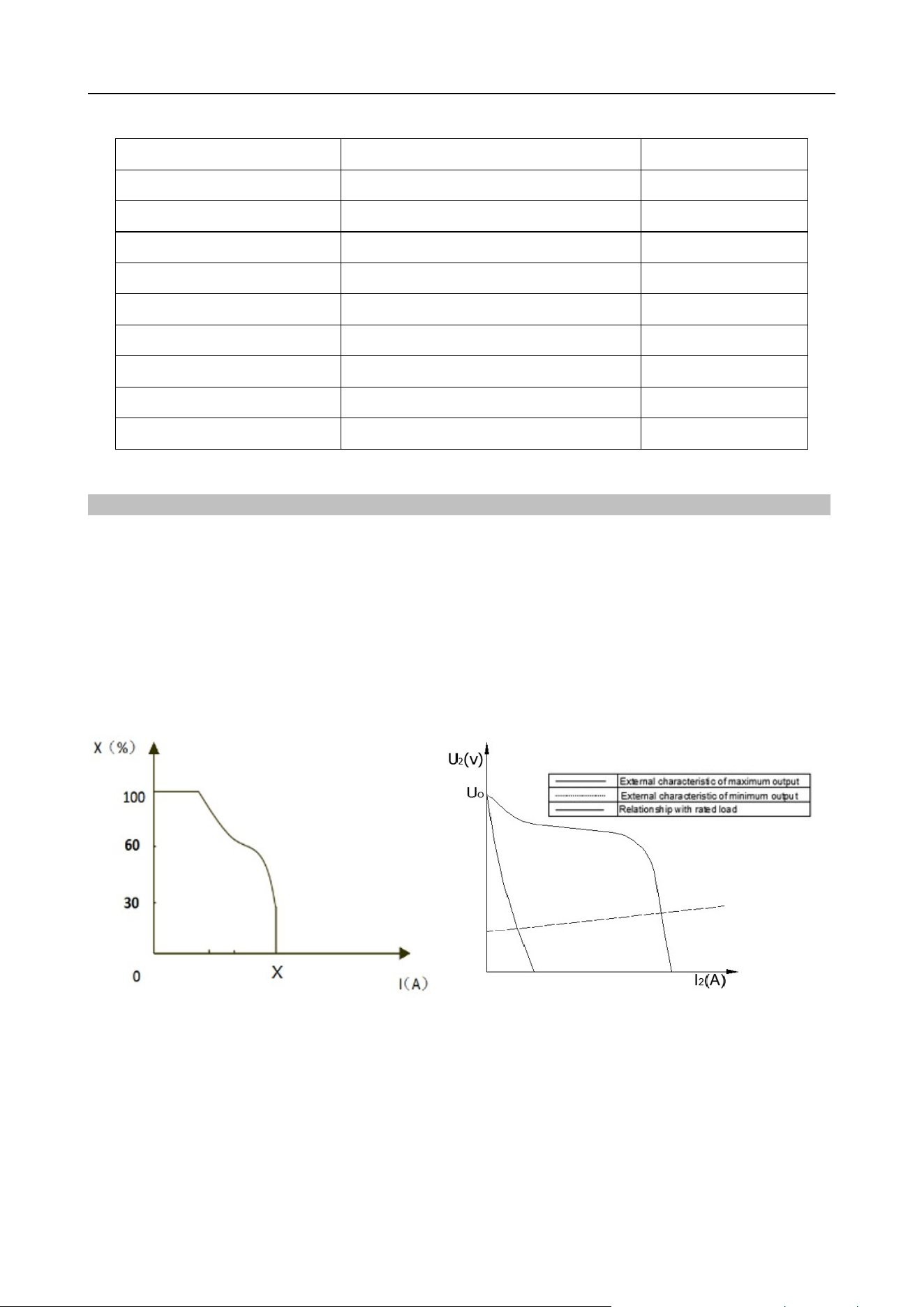
Duty Circle
Rated duty circle means: Taking 10 min as a time cycle, the ratio of rated output time is taking in that
time cycle, as shown in Pic 3.
Static External Characteristics
TIG series welders’ power output is of dropping characteristics (constant current characteristics), as
shown in Pic 4. Picture is only for reference.
Pic 3 Duty Circle Sketch Map Pic 4 Output characteristic curves
https://www.arccaptain.com/
8
3. FUNCTION
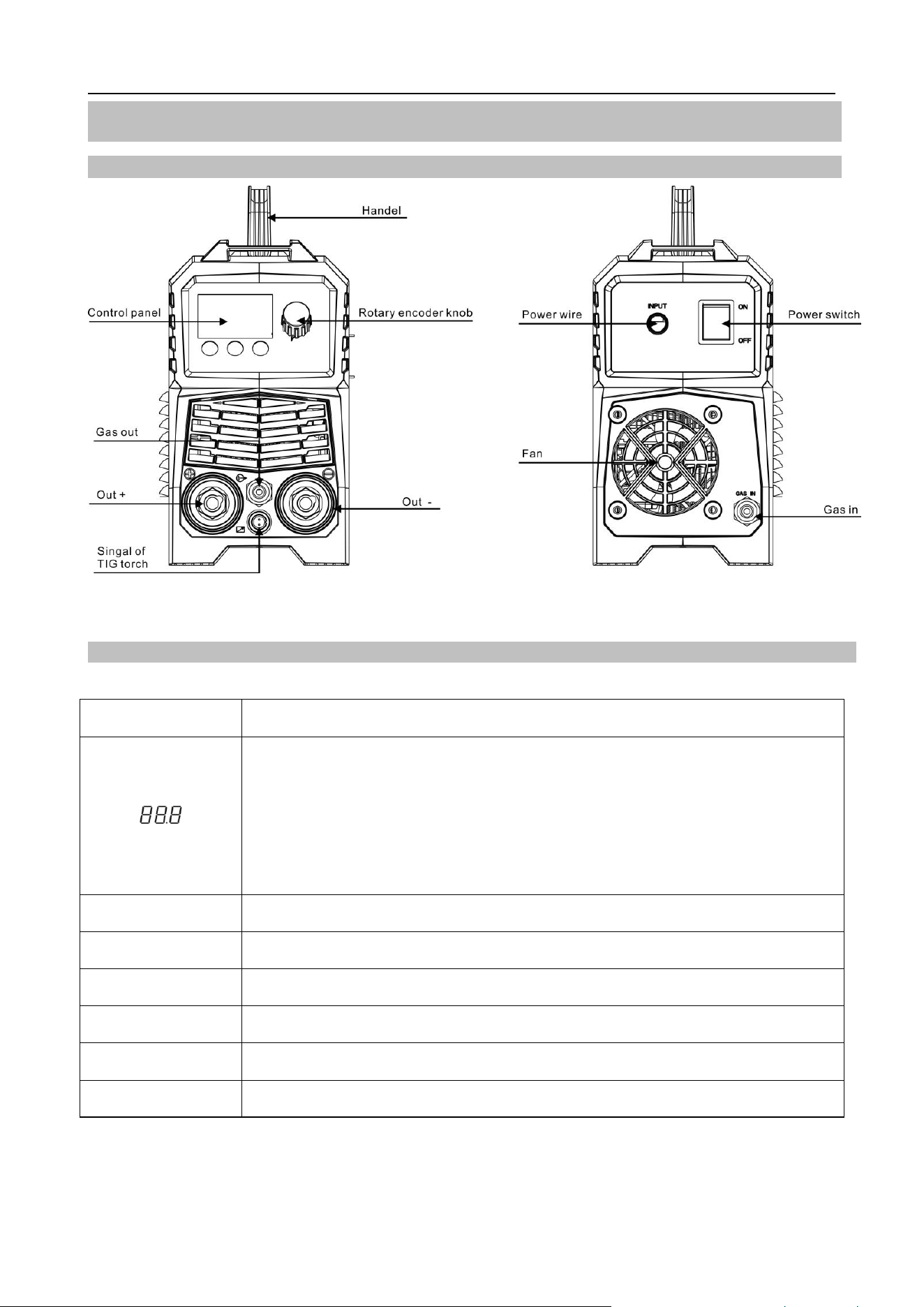
3.1 Panel of TIG200
Pic 5 Front panel of TIG200 Pic 6 Back panel of TIG200
3.2 Panel functions of TIG200
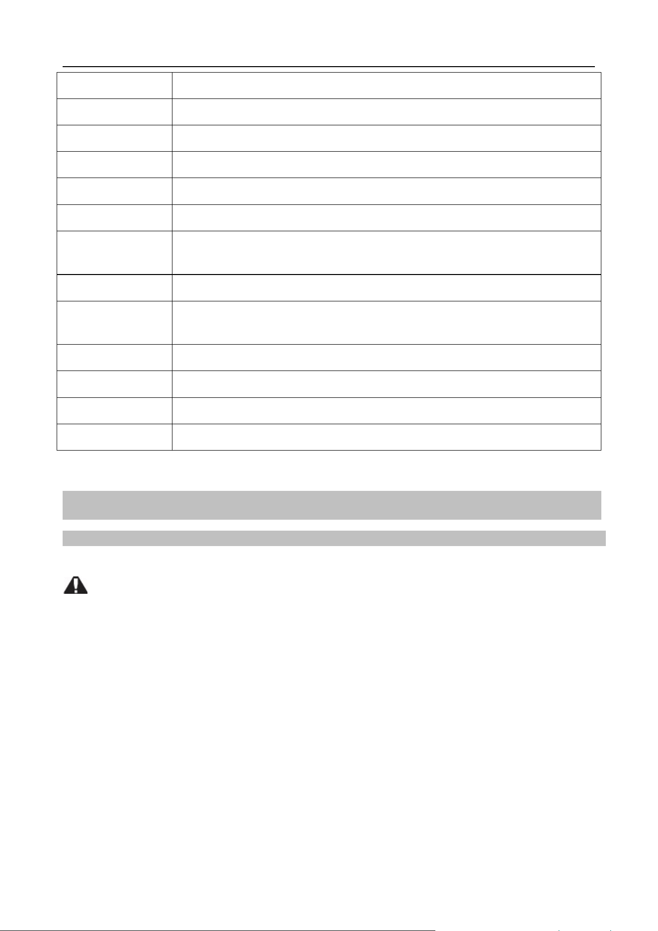
Part name Function
1.It displays parameters value which is set currently;
2.It displays setting value of Down Slope;
3.It displays setting value of Post Gas;
4.It displays “E61” code while the machine is of over-load status;
5.It displays “E10” code while the machine is over current.
~110V The input voltage is AC110V when it is blinking.
~220V The input voltage is AC110V when it is blinking.
Panel The welder can only be used by panel control when it is blinking.
Remote The welder can only be used by remote control when it is blinking.
MMA MMA Welding mode.
TIG 2T 2T Welding mode.
https://www.arccaptain.com/
9
TIG 4T 4T Welding mode.
DownSlope This indicates the time taken from the peak current to the arc striking current.
PostGas This indicates the shielding gas post-flow time.
Current This indicates the value of output current.
A Unit of current.
s Unit of time.
Welding mode
button
For MMA/2T/4T welding mode conversion.
Preference button For Down slope/Post Gas/Current conversion.
Control mode
button
For Panel/Remote conversion.
Power wire For power supply input.
Power switch To control the ON/OFF of the input power of the machine.
Fan For heat dissipation through forced air cooling.
Gas nut Used to connect external gas.
4. INSTALLATION AND CONNECTION
4.1 Installation requirements
Environment requirements
Please pay attention to the following when choosing installation site:
Please avoid environment which contains too much dusts or metal powder.
Avoid installation in area which is with corrosive or explosive gases.
Ambient temperature should be within
-
10
℃~+
40
℃
;Please reinforce radiation or lessen
power machine operation when temperature is over 40
℃
.
Installation should be carried out in dry environment with humidity less than 90%.
Avoid welding in the open air with strong wind; please install windscreen if necessary, or else
welding performances may be affected.
Please consult and confirm in advance if there is any special installation requirement.
If the Welding power is paced on tilt plane, pay attention to avoid it topple over.
The Welding power is forbidden to use thaw pipe.
https://www.arccaptain.com/

10
Installation space requirements
Distance between welder and wall should be more than 20cm
(
7.87
”)
; distance between two abreast
welders should be more than 30cm
(
11.82”
)
. You may refer to the below suggested reserved installation
space to confirm the installation position.
Department Front Left Side Right Side Back
Reserved Space ≥20cm/7.87
”
≥20cm/7.87
”
≥20cm/7.87
”
≥20cm/7.87
”
4.2 Electrical connection
Precautions:
All connection should be carried out by qualified professional electric operators.
All connection should be carried out when distribution box is switched off and safety is 100%
confirmed.
Cable section area of the distribution box should withstand welder’s max output.
Don’t touch with bare hands.
Don’t place heavy items on cables.
Water pipe, building metal may not be fully grounded; please don’t use them as safe earth
connection.
Every welder’s yellow/green cable should be reliably grounded.
https://www.arccaptain.com/
11
4.3 Installation and Commission
4.3.1 Welder operation description for TIG function
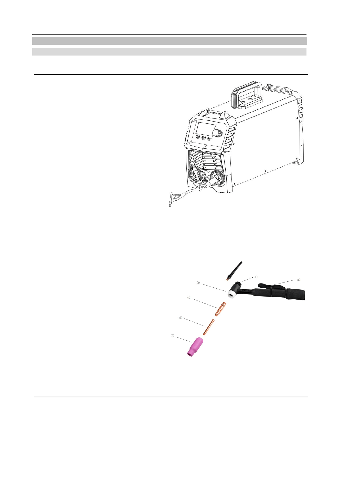
A. Connection
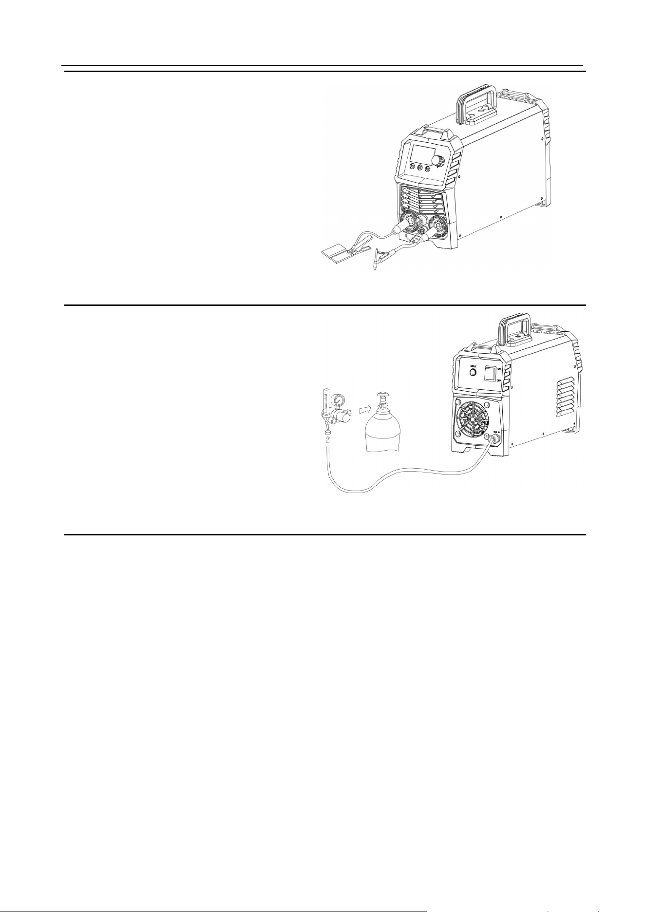
1. Please connect TIG torch correctly according
to Pic 7. Connect the gas & electric connector of
the TIG torch to the corresponding connector on
the machine panel, and tighten it clockwise.
2. Connect the aviation plug on the TIG torch to
the corresponding socket on the machine
panel. (See Pic 7.)
3. Connection of TIG torch’s components.
①
Torch trigger
②
Short/Long Back cap
③
Gasket
④
Collet Body
⑤
Collet
⑥
Ceramic nozzle
Pic 7 Installation of TIG torch
Pic 8: Connection of TIG torch
https://www.arccaptain.com/
12
B. Operation for TIG function
1) power switch
Turn on the power switch on the back panel and fan starts rotating; panel display is normal and power
supply indicator is light on; welder is successfully started.
2) TIG available:
Connect well the argon cylinder and turn on cylinder valve; adjust the flow meter to the according value;
Connect welding torch and earth clamp;
Pull the torch trigger and solenoid valve starts working; there will be argon out, also HF discharging at
the same time.
Please set welding current according to workpiece thickness.
Keep the distance between torch tungsten and workpiece at 2-4mm/0.08-0.16in; pull the torch trigger
and welder’s HF discharging noise will disappear as long as arc is successfully ignited; welding can be
4. Insert the quick plug on the earth cable into
the “+” quick socket on the machine panel, and
tighten it clockwise. Clamp the workpiece with
the earth clamp at the other end of the earth
cable. (See Pic 9.)
Pic 9 Installation of Earth cable
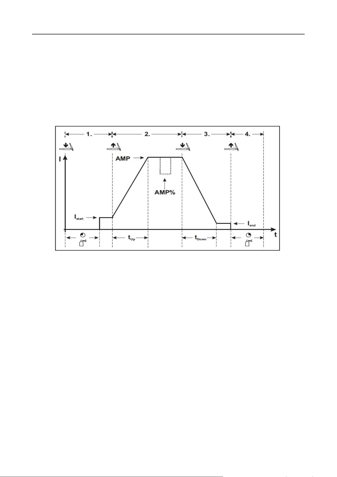
5. Gas connection: connect argon tube with
welder back panel’s brass mouthpiece tightly.
Air supply passage should include argon
decompressed flowmeter, gas hose; please use
a hose clamp or other fixing items to crew the
hose connection part so that to avoid poor
welding spot protection which is caused by gas
leakage or air admission. (Pic 10)
Pic 10 Gas connection
https://www.arccaptain.com/
13
started;
3) Current regulation
Operators can choose according to welding current per workpiece thickness.(current range:10-200A)
4) Post-flow time
Post-flow time is the time between arc ending and post-flow. Post-time can be adjusted between
1-10seconds.
5) down slope time
:
to adjust the output current down slope time.
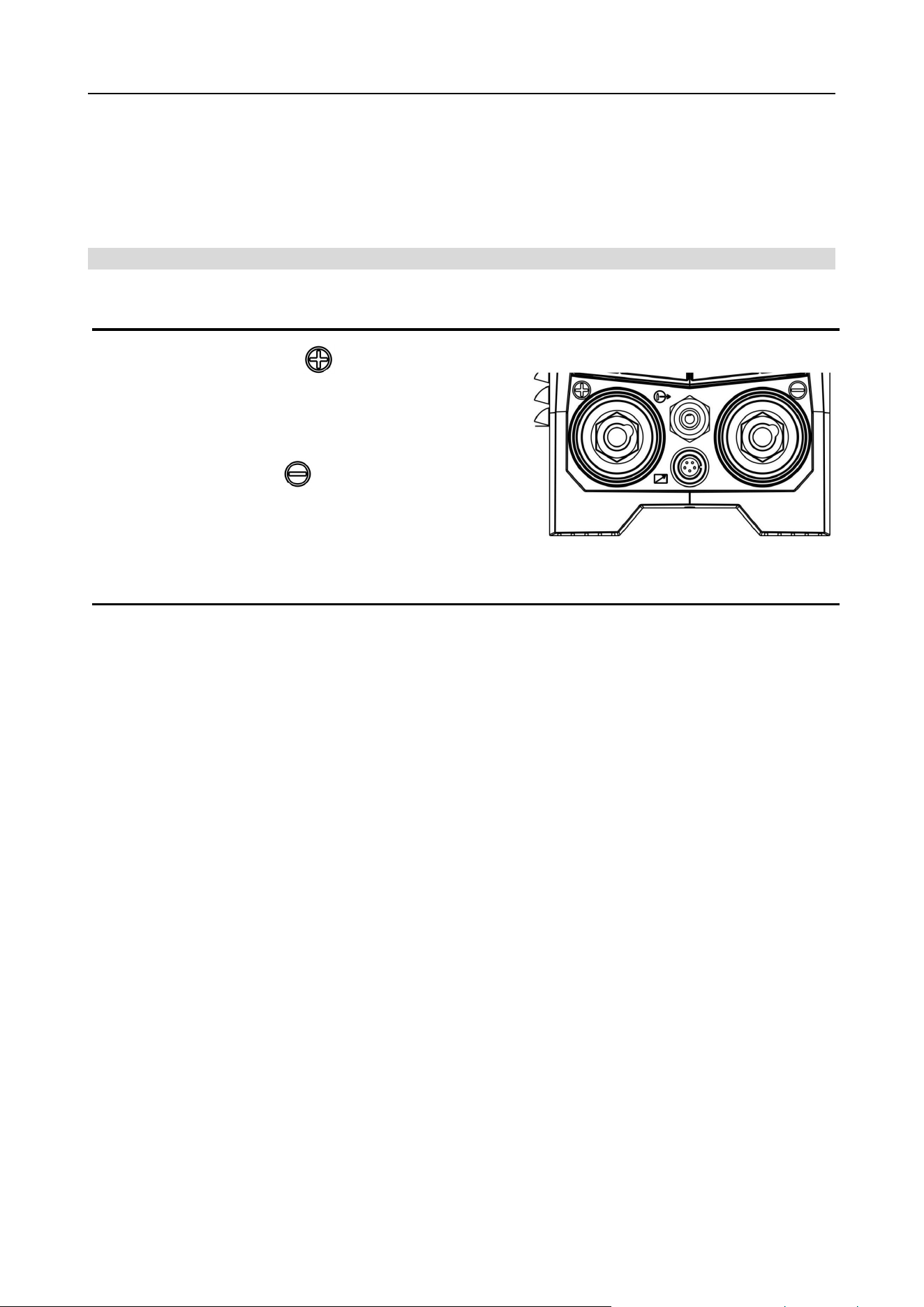
6) 2T/4T :select 4T
【
The up- and down-slopes are switched off
】
.
Pic 11 4T welding logic
Step 1
• Press torch trigger 1, there is gas pre-flow time
(
150ms).
• HF ignition pulses from the electrode to the workpiece, the arc ignites.
• Welding current flows and immediately the ignition. HF is switched off.
Step 2
• Release torch trigger 1.
• The welding current increases with the set up-slope time( built-in 0 second) to the main current AMP.
Switching from main current AMP to secondary current AMP%:
Press torch trigger 2 or Tap torch trigger 1 *
Step 3
• Press torch trigger 1.
• The main current drops with the set down-slope time to the end-crater current Iend (minimum current).
Step 4
• Release torch trigger 1, the arc extinguishes.
• The set gas post-flow time begins.
Immediate termination of the welding process in the downslope by releasing torch trigger 1.
https://www.arccaptain.com/
14
7) pulse frequency adjust
:
to adjust the output current pulse frequency.
8) remote control
Adjustable welding current depending on the TIG torch of potentiometer/or foot pedal. (not included in
basic package)
4.3.2 Welder operation description for MMA function
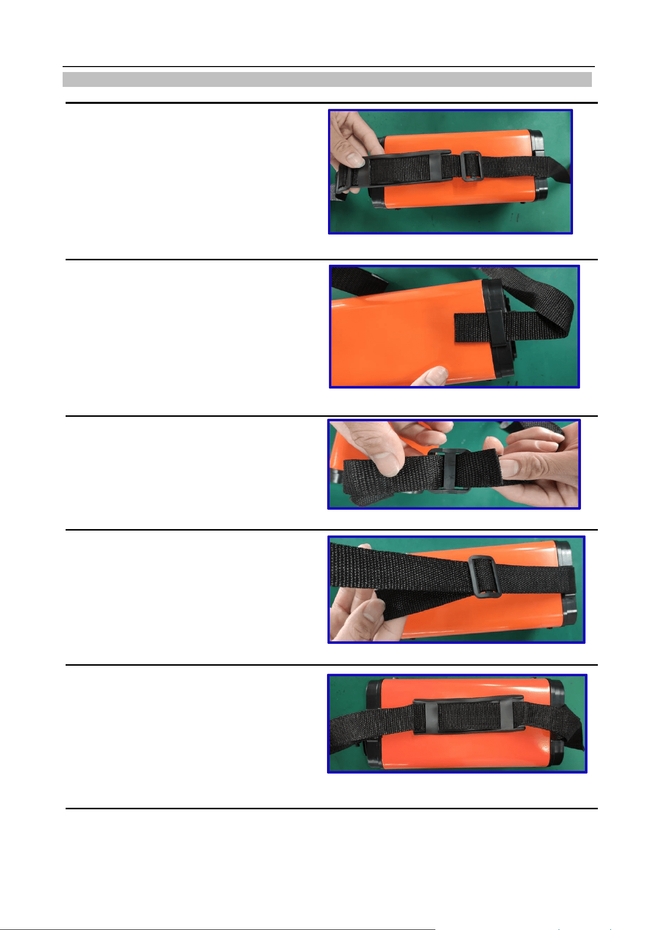
Connecting the electrode holder and workpiece lead
• Insert cable plug of the electrode holder into either the "+" or "-" welding current connection socket and
lock by turning to the right.
• Insert cable plug of the workpiece lead into either the "+" or "-" welding current connection socket and
lock by turning to the right.
Polarity depends on the instructions from the electrode manufacturer given on the electrode packaging.
1. Connection socket for " " welding current
Electrode holder or workpiece lead connection
2. Connection socket, “ ” welding current
Workpiece lead or electrode holder connection
Pic12 Lower part of front panel
https://www.arccaptain.com/
15
4.4 Strap Installation
Step 1: Separate the velcro.(See Pic 13)
Pic 13
Step 2: Pull out one side through the strap hole
on the front panel with hook side of the velcro
up.(See Pic 14)
Pic 14
Step 3: Pull out it to well stick hook side of the
velcro to loop side and across the nylon buckle.
Repeat it on the other side.(See Pic 15)
Pic 15
Step 4: Adjust the length by pulling the nylon
buckle (as shown in the picture).(See Pic 16)
Pic 16
Step 5: Proper state after installation:
1. Strap does not twist;
2. Buckle side of shoulder pad is up, while its
flat side faces the machine (as shown in the
picture);
3. Straps are well locked.(See Pic 17)
Pic 17
https://www.arccaptain.com/
16
5. WELDING PARAMETERS TABLE
Parameters for TIG electrode
Electrode diameter
Amperage range
on DCEN Straight
polarity
Amperage range on
DCEP Straight polarity
Amperage range on AC
mm inch
1
.040" 15-80 / 20-60
1.6 1/16 70-150 10-20 60-120
2.4 3/32" 150-250 15-30 100-180
3.2 1/8" 250-400 15-40 160-250
4 5/32" 400-500 40-55 200-320
Parameters for TIG welding on stainless steel sheet (for reference only)
Electrode diameter mm
(inch)
Plate thickness mm
(inch)
Welding current(A) Gas flow(L/min)
1~2mm
(0.040”-5/64”)
1~3mm
(0.040”- 0.12”)
50 5
50~80 6
2~4mm
(5/64”-5/32 “)
3~6mm
(0.12”-0.24”)
80~120 7
121~160 8
161~200 9
201~300 10
https://www.arccaptain.com/

17
Parameters for TIG welding on titanium and its alloy (for reference only)
Plate
thickness
mm (inch)
Weldin
g
layers
Electrode
diameter mm
(inch)
Wire
diameter mm
(inch)
Welding
current(
A)
Gas flow (L/min)
Nozzle
diameter
mm (inch)
Square
groove
Single V
groove
with root
face
Double V
groove
with root
face
0.5(0.020") 1 1.5(0.059") 1 (0.040") 30~50 8~10 6~8 14~16 10(0.393")
1 (0.040") 1 2(0.079")
1.0~2.0
(0.040"-0.079")
40~60 8~10 6~8 14~16 10(0.393")
1.5(0.060") 1 2(0.079")
1.0~2.0
(0.040"-0.079")
60~80 10~12 8`10 14~16
10~12
(0.393"-0.472)
2(0.079") 1
2.0~3.0
(0.079"-0.118")
1.0~2.0
(0.040"-0.079")
80~110 12~14 10~12 16~20
12~14
(0.472"-0.551")
2.5(0.098") 1
2.0~3.0
(0.079"-0.118")
2 (0.079") 110~120 12~14 10~12 16~20
12~14
(0.472"-0.551")
3(0.118") 1~2 3(0.12")
2.0~3.0
(0.079"-0.118")
120~140 12~14 10~12 16~20
14~18
(0.551"-0.708")
4(0.157") 2
3.0~4.0
(0.12~5/32")
2.0~3.0
(0.079"-0.118")
130~150 14~16 12~14 20~25
18~20
(0.708"-0.787")
5(0.197") 2~3 4.0(5/32”) 3(0.118") 130~150 14~16 12~14 20~25
18~20
(0.708"-0.787")
6(0.236") 2~3 4.0(5/32”)
3.0~4.0
(0.118"-5/32”)
140~180 14~16 12~14 25~28
18~20
(0.708"-0.787")
7(0.257") 2~3 4.0(5/32”)
3.0~4.0
(0.118"-5/32”)
140~180 14~16 12~14 25~28
20~22
(0.787"-0.866")
8(0.315") 3~4 4.0(5/32”)
3.0~4.0
(0.118"-5/32”)
140~180 14~16 12~14 25~28
20~22
(0.787"-0.866")
10(0.394") 4~6 4.0(5/32”)
3.0~4.0
(0.118"-5/32”)
160~200 14~16 12~14 25~28
20~22
(0.787"-0.866")
20(0.787") 12 4.0(5/32”) 4(5/32”) 200~240 12~14 10~12 20 18(0.708")
22(0.866") 12 4.0(5/32”)
4.0~5.0
(5/32”-0.197")
230~250 15~18 18~20 18~20 20(0.787")
25(0.984") 15~16 4.0(5/32”)
3.0~4.0
(0.118"-5/32”)
200~220 16~18 20~26 26~30 22(0.866")
https://www.arccaptain.com/
18
30(1.181") 17~18 4.0(5/32”)
3.0~4.0
(0.118"-5/32”)
200~220 16~18 20~26 26~30 22(0.866")
6.MAINTENANCE
6.1 Daily maintenance
Tips:
1) Daily checking is very important in keeping the high performance and safe operation of this welding
machine.
2) Do daily checking according to the table below, and clean or replace components when necessary.
3)
In order to ensure the high performance of the machine, please choose components provided or
recommended by dealer when replacing components.
Daily checking of the welding machine
Item Checking requirements Remark
Front panel
Whether any of the components are damaged or
loosely connected;
Whether the output quick sockets are tightened;
Whether the abnormity indicator illuminates.
Front panel quick socket is a
required checking item.
If
unqualified, check the
interior of the machine, and
tighten or replace the
components.
Back panel
Whether the input power cable and buckle are in
good condition;
Whether the air intake is unobstructed.
Cover
Whether the bolts are loosely connected.
If unqualified, tighten or
replace the components.
Chassis
Whether the side plate is loosely fixed.
Side plates
Whether the screws are loosely connected.
Routine
Whether the machine enclosure has color fading or
overheating problems;
Whether the fan sounds normal when the machine is
running;
Whether there is abnormal smell, abnormal vibration
or noise when the machine is running.
If abnormal, check the
interior of the machine.
Warning
The following operation requires professional knowledge on electric application and comprehensive
safety knowledge. Operators should be licensed with related qualification certificates (still in validation)
which can prove their skills and knowledge. To avoid personal injury accidents such as electric shock
and burns, please make sure the power supply is cut off before uncovering the welding machine.
https://www.arccaptain.com/
19
Daily checking of other items
Item Checking requirements Remark
Earth cable
Whether the grounding wires (including workpiece
GND wire and welding machine GND wire) are
loosened.
If unqualified, tighten or
replace the components.
Welding cable
Whether the insulating layer of the cable is worn, or
the conductive part of the cable is exposed;
Whether the cable is drawn by an external force;
Whether the cable connected to the workpiece is well
connected.
Use appropriate methods
according to the work site
situation to ensure safety
and normal welding.
Gas hose
Whether gas hose is tightly connected;
Whether hose clamp is tightly connected;
Whether hose pipe is worn out or has any leakage.
If unqualified, tighten or
replace the components.
6.2 Periodic maintenance
Warning
1. To ensure your safety, periodic check can only be carried out by qualified professionals.
2. Please shut down the switching box and the welding machine before periodic check to
avoid personal injury accidents such as electric shock and burns.
3. Due to capacitors’ discharge, all checking should be carried out 5 minutes after the machine
is powered off.
Tips Remarks
Safety
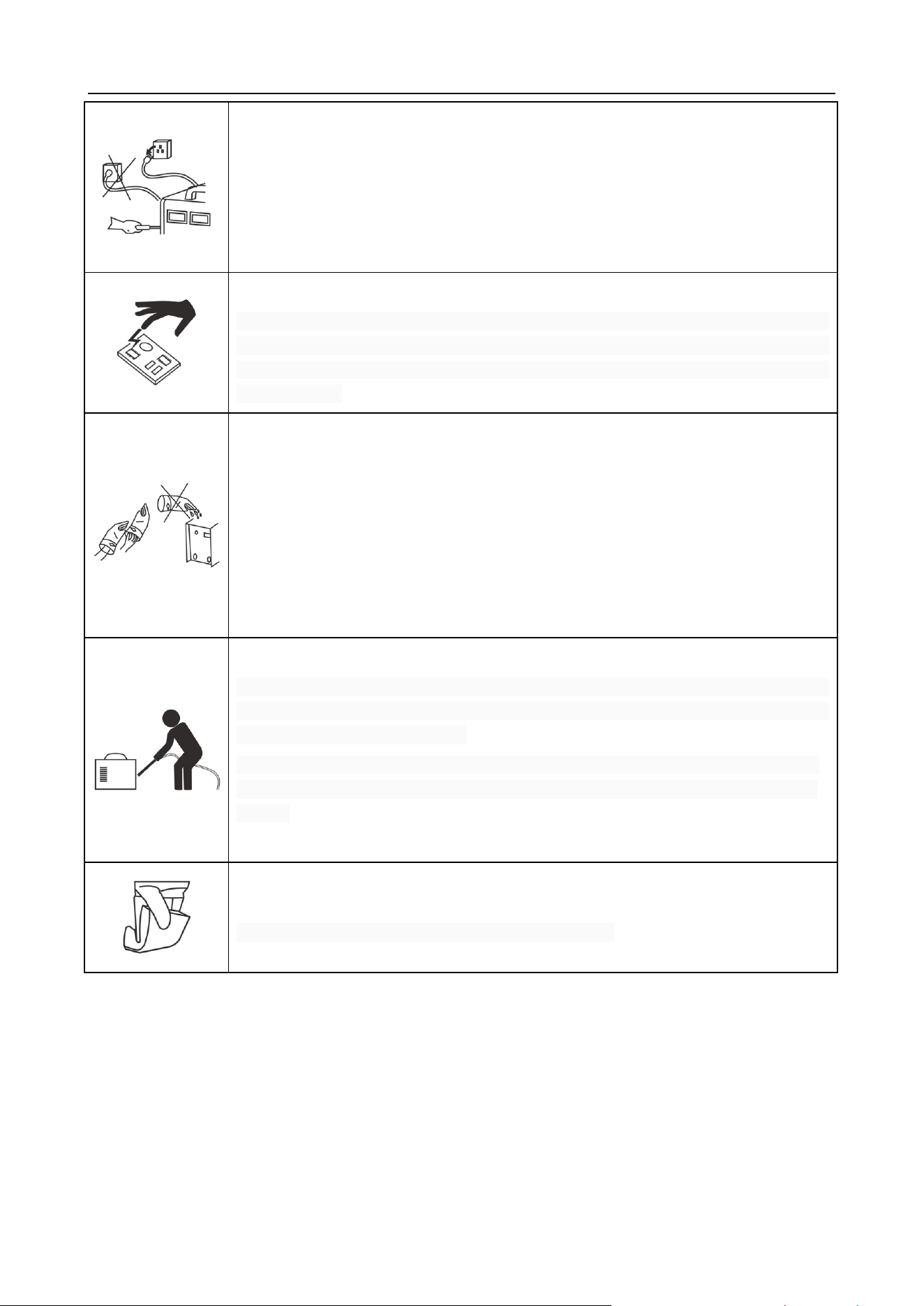
All maintenance and checking should be carry out after the power is completely cut
off. Make sure the power plug of the machine is pulled out before uncovering the
welding machine.
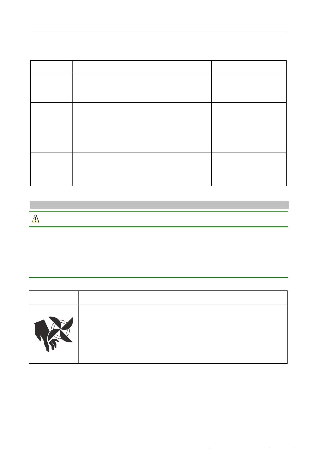
When the machine is powered on, keep hands, hair and tools away from the
moving parts such as cooling fan, to avoid personal injury or machine damage.
https://www.arccaptain.com/
20
Periodic check
Check periodically whether inner circuit connection is in good condition (esp. input
plugs or other components). Tighten the loose connection. If there is any
oxidization, remove it with sandpaper before reconnect them.
Check periodically whether the insulating layer of all cables is in good condition. If
there is any dilapidation, rewrap it or replace it.
Beware of static
In order to protect the semiconductor components and PCBs from the static
damage, please wear antistatic device or touch the metal part of the enclosure to
remove static before any contacting with the conductors and PCBs of the machine
internal wiring.
Keep it dry
Avoid rain, water and vapor infiltrating the machine. If there is any damp, dry it and
check the insulation of the welding machine (including all wires connections and
connections with the enclosure) with an ohmmeter. Only after the confirmation of
no abnormity, w, can the machine be used.
Put the machine into the original packing in dry places if will not be used for a long
time.
Pay attention to maintenance
Periodic check should be carried out to ensure the long-time well operation of the
machine. Be careful when doing the periodic check, including the inspection and
cleaning of the machine interior.
Generally, periodic check should be carried out every 6 months, and it should be
carried out every 3 months if the welding environment is dusty or with heavy oily
smoke.
Beware of corrosion
Please clean the plastic parts with neutral detergent.
https://www.arccaptain.com/
21
7.FAILURE DIAGNOSIS AND TROUBLESHOOTING
Warning
All welder maintenance should be carried out by qualified professional operators; any wrong
connection or installation will damage to PCB or components. To avoid electric shock, burning or
other personal injuries, please do maintenance 5 minutes after welder is powered off.
Please do the following inspection before maintenance:
1) Please check if welder input voltage is within 220V/110V±15%.
2) Please make sure the correct and tight connection of input cable.
3) Please make sure the correct and tight connection of welding cable.
4) Please make sure gas circulation is normal; please use pure argon gas and adjust gas flow per
actual welding demands.
5) Please make sure all PCB terminals are correctly and tightly connected.
Error code and welding processing problems
Welder failure and welding process problems
Malfunction phenomena
Solutions
Power supply indicator doesn’t light
Fan doesn’t work and there is no
current output
1.Please make sure power switch is on.
2.Please make sure there is electricity input.
Power supply indicator lights
Fan doesn’t work and there is no
current output
1.Under-powered DC24V supply or main replay is not closed.
2.Check if DC15V power supply is normal or not.
Fan works; but output current is not
stable or can’t be controlled by
potentiometer;
1. front panel potentiometer is not working.
2. electrolytic capacitor is failed.( replace a capacitance).
3. Poor connection.
https://www.arccaptain.com/

22
Fan works; abnormity light doesn’t
light, but with no welding output;
1.Make sure operator has pulled the torch trigger and make sure
it’s in good contact.
2.Check whether DC15V power supply is normal;
3.Check whether drive wire is tightly connected.
4.Check whether panel potentiometer is open-circuited.
5.Output terminal connection is in poor connection.
Fan is working; abnormity indicator
lights, but with no welding output;
1.Might be over-current protection; please turn off the machine;
restart the machine when abnormity indicator stop lighting, and
welder will go back to normal operation;
2.Might be over-heat protection; waif for 5-7 minutes and machine
will go back to normal operation automatically;
3.Might be caused by a failed thermistor on radiator; replace it with
a new one;
4. Might be caused by a failed IGBT on inverter PCB.
Black welding spot
1.Please make sure argon outlet from welding torch nozzle is
normal.
2.Argon flow is too small; generally argon flow should be 5L/min
;
3.Please check whether air circulation is in good sealing condition
and please check gas purity;
4.Please make sure there is no strong airflow in the welding site.
Poor protection for welding bead in
the end of welding processing.
1. Don’t move the welding torch immediately after welding is
finished, so that to retain the shielding gas’s protection for high
temperature welding bead.
2. Prolong post-flow time.
Hard to achieve successful arc
ignition; frequent current interruption.
1.Change a new tungsten;
2.Remove tungsten oxidation layer.
3.Prolong post-flow time;
4.Adjust tungsten electrode discharge distance(around0.8mm)
https://www.arccaptain.com/

23
Unstable welding current
1.Please make sure power network is normal.
2.Connect different power input cables if there are other
equipments of strong interferences.
No HF discharge when pull the torch
trigger
1.Please check whether OCV is normal
(
DC62V
);
2.Please make sure torch trigger control loop is normal
(
LED3 will
light up when pull torch trigger
);
3.Please check whether HF control loop is normal;
Display indicates E10
1.Restart machine.
2.Check if flat cable between front PCB and top PCB is well
connected.
3.If it is not fixed, the circuit fails. Please contact your distributor.
Display indicates E61
1.The thermistor is not well connected to control board.
2.The thermistor is damaged. Please replace it.
https://www.arccaptain.com/

24
https://www.arccaptain.com/