
Dear Valued Customer,
Thank you for going with ARCCAPTAIN! We're all about making welders superior for you.
ARCCAPTAIN was built by high quality components, every single unit machine was passed
multiple industry leading laboratory tests to provide a great welding experience and
performance.
Two-year warranty service is provide to yours! When unpacking, make sure that the
product is intact and undamaged. DO NOT return directly before contact our customer
service.
Six ways to connect us and join in ARCCAPTAIN Community:
Email: [email protected]
Online: www.arccaptain.com/pages/contact-us
Facebook: arccaptainwelder
Instagram: arccaptain_welder
Youtube: arccaptain-weld
Whatsapp: +19892449456
This manual is designed to help you get the most out of your ARCCAPTAIN products.
Please save this manual and take time to read the safety warnings and precautions,
assembly, operating, inspection, maintenance. They will help you protect yourself against
potential hazards on the worksite. Failure to do so can result in serious injury!
www.arccaptain.com
Save for future reference:
Product:
Date Purchased:
Serial Number:
Product Feedback:

User Manual
1.SAFETY ----------------------------------------------------------------------------------------------------------------- 1
1.1 General Safety ------------------------------------------------------------------------------------------------- 1
1.2 Electrical Safety ------------------------------------------------------------------------------------------------1
1.3 Fire Safety -------------------------------------------------------------------------------------------------------2
1.4 Fumes and Gases Safety ----------------------------------------------------------------------------------- 2
1.5 Arc Rays and Notice Safety ---------------------------------------------------------------------------------2
1.6 Gas Shielded Welding – Cylinder Safety ---------------------------------------------------------------- 3
1.7 Additional Safety Information ------------------------------------------------------------------------------- 3
2.PRODUCT DESCRIPTION ----------------------------------------------------------------------------------------- 3
2.1 Product Overview ----------------------------------------------------------------------------------------------3
2.2 Package --------------------------------------------------------------------------------------------------------- 4
2.3 Technical Parameters ---------------------------------------------------------------------------------------- 5
2.4 Nameplate -------------------------------------------------------------------------------------------------------6
3.FUNCTION --------------------------------------------------------------------------------------------------------------7
3.1Panel of TIG200P ---------------------------------------------------------------------------------------------- 7
3.2 Panel functions of TIG200P ---------------------------------------------------------------------------------8
4.INSTALLATION AND CONNECTION -------------------------------------------------------------------------- 11
4.1 Installation requirements ----------------------------------------------------------------------------------- 11
4.2 TIG Welder Cable Connection ----------------------------------------------------------------------------12
4.3 LIFT TIG Welder Cable Connection --------------------------------------------------------------------- 13
4.4 Input Power Connection ------------------------------------------------------------------------------------15
4.5 TIG Welder Operation -------------------------------------------------------------------------------------- 16
4.6 TIG Welding Mode -------------------------------------------------------------------------------------------18
4.7 Installation for MMA function ------------------------------------------------------------------------------ 19
4.8 MMA Welding Mode -----------------------------------------------------------------------------------------20
4.9 MMA Welding Parameters Table ------------------------------------------------------------------------- 20
5. STRAP INSTALLATION ------------------------------------------------------------------------------------------ 21
6. WELDING PARAMETERS TABLE -----------------------------------------------------------------------------22
6.1 Parameters for TIG electrode ----------------------------------------------------------------------------- 22

6.2 Parameters for TIG welding on stainless steel sheet ----------------------------------------------- 22
6.3 Parameters for TIG welding ------------------------------------------------------------------------------- 23
7. BASIC KNOWLEDGE OF TIG WELDING ------------------------------------------------------------------- 24
7.1 TIG Overview and Characteristics ----------------------------------------------------------------------- 24
7.2 TIG Characteristics ------------------------------------------------------------------------------------------ 24
7.3 TIG Welding Gun -------------------------------------------------------------------------------------------- 25
7.4 TIG Process --------------------------------------------------------------------------------------------------- 26
7.5 Welding Parameters ---------------------------------------------------------------------------------------- 28
7.6 General Requirements of TIG ---------------------------------------------------------------------------- 29
8. BASIC KNOWLEDGE OF MMA -------------------------------------------------------------------------------- 29
8.1 Welding Process Of MMA --------------------------------------------------------------------------------- 29
8.2 Tools For MMA ----------------------------------------------------------------------------------------------- 30
8.3 Basic Operation Of MMA ---------------------------------------------------------------------------------- 30
9. TROUBLESHOOTING -------------------------------------------------------------------------------------------- 33
9.1 Error code and welding processing problems -------------------------------------------------------- 34
10. MAINTENANCE --------------------------------------------------------------------------------------------------- 35
https://www.arccaptain.com/
1
1.SAFETY
! WARINING READ ALL SAFETY WARNINGS BEFORE WORKING!
Failure to follow the warnings and instructions may result in electric shock, fire and/or serious injury.
Save all warnings and instructions for future reference!
If you encounter any issues during installation or operation, refer to the relevant sections in this manual
for inspection. If you're still unsure or unable to resolve the problem, please contact ARCCAPTAIN
professional support.
1.1 General Safety
Do NOT use the welder if the switch does not turn it on and off.
Disconnect the plug from the power source before making any adjustments, changing accessories,
or storing the welder.
Ensure the switch is off before connecting to power or moving the welder to prevent accidental
starting.
Always maintain and use safety guards, covers, and devices properly.
Keep hands, hair, clothing, and tools away from moving parts like V-belts, gears, and fans.
Follow these instructions and consider working conditions when using the welder and accessories.
This manual may not cover every possible situation. It's important for the operator to use common
sense and caution while using this product.
1.2 Electrical Safety
! WARINING BEWARE OF ELECTRIC SHOCK!
DO NOT weld in a damp area or come in contact with a moist or wet surface.
DO NOT modify any wiring, ground connections, switches, or fuses in this welding equipment.
DO NOT come into physical contact with any part of the welding current circuit, including the
workpiece, ground clamp, electrode or welding wire, and metal parts on the electrode holder or MIG
gun.
DO NOT connect the ground clamp to electrical conduit, and DO NOT weld on electrical conduit.
NEVER leave the Welder unattended while energized. Turn off the power if you have to leave.
DO NOT attempt to plug the welder into the power source if the ground prong on INPUT POWER
CABLE plug is bent over, broken off, or missing.
DO NOT alter INPUT POWER CABLE or plug in any way.
People with pacemakers should consult their physicians before use. Magnetic field can make
cardiac pacemaker a bit wonky.
https://www.arccaptain.com/
2
! WARINING REPLACING COMPONENTS CAN BE DANGEROUS!
Only experts should replace machine parts. Avoid dropping foreign objects into the machine during
component replacement. Ensure correct wire connections after replacing PCBs to prevent property
damage.
1.3 Fire Safety
! WARINING BEWARE OF FIRE HAZARD!
Place the machine on non-combustible surfaces to prevent fires.
Ensure no flammable materials are near the working area to reduce fire risk.
Avoid installing the machine near water sources to prevent water damage.
Always weld/cut materials in a dry environment with humidity below 90% and maintain a working
temperature between -10°C and 40°C.
When welding/cutting outdoors, ensure shelter from sunlight and rain, keeping the machine dry at
all times.
Do not operate the machine in dusty or chemically corrosive environments.
Remove or secure all combustible materials within a 35 feet (10 meters) radius of the work area.
Use fire-resistant material to cover or seal open doorways, windows, cracks, and other openings.
Improper use can lead to fire or explosion. Avoid flammable materials near the working area, keep a
fire extinguisher nearby with trained personnel, refrain from cutting closed containers, and do not
use the machine for pipe thawing.
1.4 Fumes and Gases Safety
! WARINING SMOKE CAN BE HARMFUL TO YOUR HEALTH!
Keep your head away from the smoke while cutting to avoid breathing in harmful gases.
Ensure the working area is well-ventilated with exhaust or ventilation equipment during cutting.
Only work in a confined area if it's well-ventilated, or wear an air-supplied respirator.
1.5 Arc Rays and Notice Safety
! WARINING
Arc radiation can harm eyes and skin; excessive noise can damage hearing.
Use certified welding eye protection with at least a number 10 shade lens rating.
Wear leather leggings and fire-resistant shoes or boots; avoid clothing that can catch sparks or
EXCESSIVE NOISE DOES GREAT HARM TO HEARING!
ARC RADIATION MAY HURT YOUR EYES AND BURN YOUR SKIN!
https://www.arccaptain.com/

3
molten metal. Do not touch hot workpiece with bare hands.
Keep clothing free of flammable substances and wear dry, insulating gloves and protective clothing.
Wear an approved head covering and use appropriate welding attire.
When welding overhead or in confined spaces, use flame-resistant ear plugs or ear muffs.
Wear ear covers or other hearing protectors when cutting.
1.6 Gas Shielded Welding – Cylinder Safety
! WARINING CYLINDERS CAN EXPLODE WHEN DAMAGED!
Never weld on a pressurized or closed cylinder.
Avoid letting the electrode holder, electrode, welding torch, or welding wire touch the cylinder.
Keep cylinders away from all electrical circuits, including welding circuits.
Always keep the protective cap on the valve except when the cylinder is in use.
Use only the correct gas shielding equipment designed for your specific type of welding, and
maintain it properly.
Protect gas cylinders from heat, physical damage, slag, flames, sparks, and arcs.
Always follow proper procedures when moving cylinders.
Do not install the machine in an environment with explosive gas to avoid an explosion.
1.7 Additional Safety Information
Use only the supplied power cord for this welder or an identical replacement cord. Do not install a
thinner or longer cord on this Welder.
Maintain labels and nameplates on the Welder. These carry important information.
Ensure the ground clamp is securely connected to the workpiece during welding.
Pressing the gun switch when welding or cutting.
When disposing of the cutting machine, please note the following:
Burning electrolytic capacitors on the main circuit or PCB board may cause explosions. Burning
plastic components such as the front panel may produce toxic gases. Dispose of it as industrial
waste.
2.PRODUCT DESCRIPTION
2.1 Product Overview
TIG welder is of constant current external characteristic. Welding current will not be changed per arc
length but being kept at a very stable level. It adopts PWM technology and high-power switching
element IGBT (discrete) to rectify AC110V/AC220V (50Hz/60Hz) voltage to DC310V, after inverting
it to 45KHz, there is a voltage step-down and rectification again, stable welder current is obtained by
output current feedback and adjustment.
Built-in MCU technology and IGBT inverter Welder, totally digital control, which ensures great and
stable welding performance.
https://www.arccaptain.com/
4
Supports DC TIG, DC pulse TIG , Lift TIG and MMA.
MMA/Stick welding features: hot start, arc force and anti-stick.
Multiple TIG operation modes: 2T, 4T and spot welding.
Smart fan control: Saves energy, reduces noise, reduces dust entry, and prolongs the service life of
the fan.
TIG arc starting mode: Supports HF and lift arc starting with a high success rate.
Portable and Lightweight: ??.??lb(unknown), carry with handle or shoulder strap.
Safety protection: over current/over voltage/overheating protection circuit.
Unique Design & LED Display Panel, read data more clear, concise distribution and convenient
operation. Warning indicator for normal working and abnormal working.
Remote control function available: support foot pedal & analog torch (purchase additional if need).
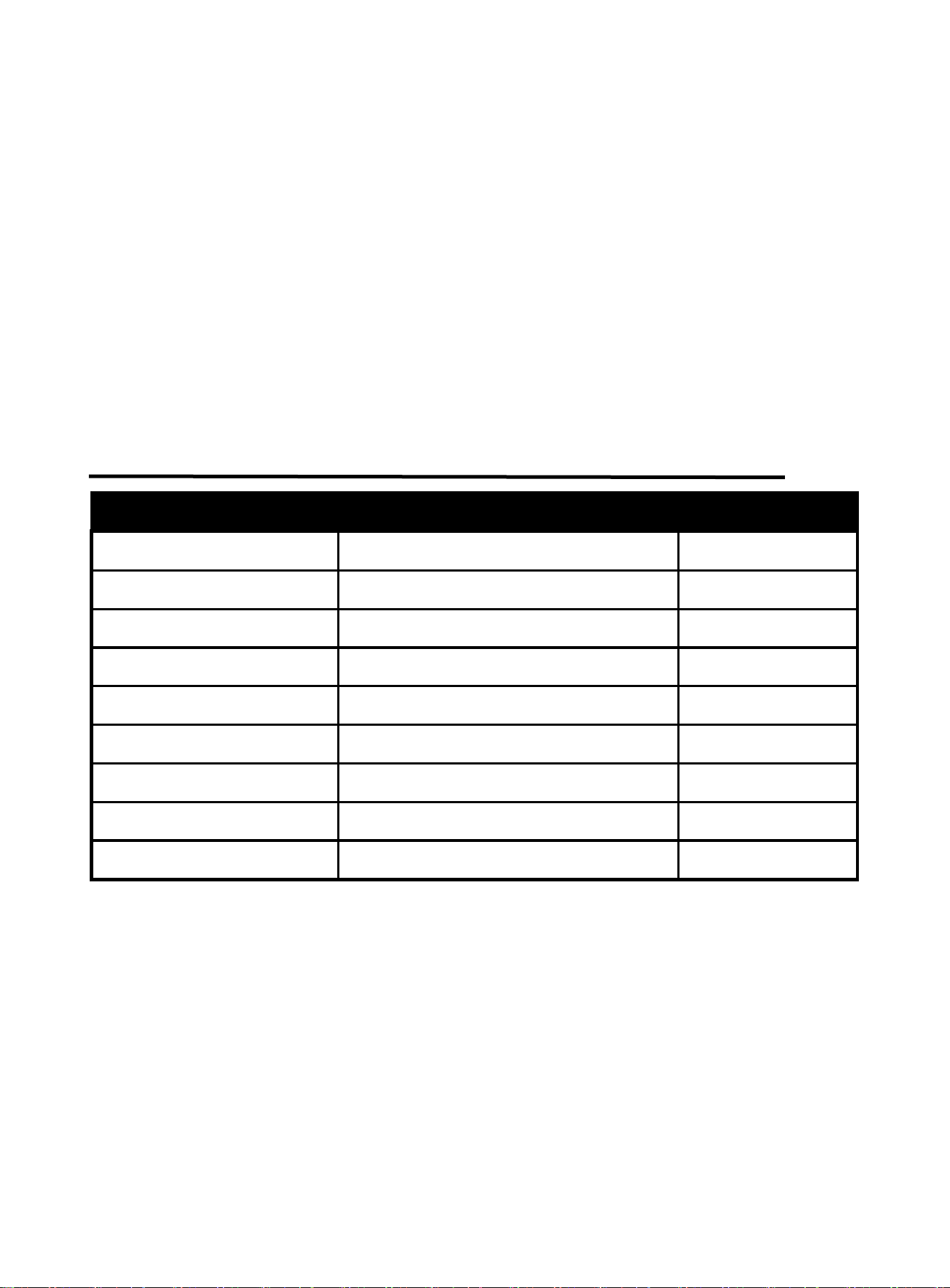
2.2 Package
Name Specification Quantity (pcs)
TIG welder TIG200P AC 1
TIG torch & accessories WP-26 (13ft/4m) 1
Electrode Holder 200A-16mm2 (9ft/ 3m)DKJ 35-50 1
Earth clamp 300A-16mm2(9ft/ 3m)DKJ 35-50 1
Operator’s manual Operator’s manual of TIG200P 1
Gas hose Gas hose with gas connector 1
Conversion adapter American adapter plug 1
Strap 0.1*4.3ft (30mm*1500mm), Black 1
Tungsten electrode φ1/16”, 6”(1.6mm, 150mm) 1
https://www.arccaptain.com/
5
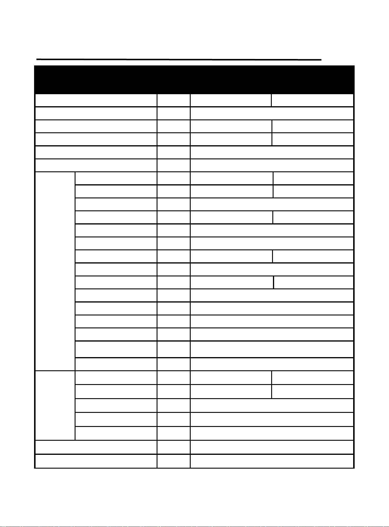
2.3 Technical Parameters
TECHNICAL PARAMETERS Units
Model
TIG200P AC
Input voltage VAC AC220V ±15% AC110V ±15%
Input frequency Hz 50/60
Rated input current A 29.2@TIG 36@MMA 31@TIG 39.4@MMA
Rated input power kVA 6.4@TIG 7.9@MMA 3.4@TIG 4.3@MMA
No-load voltage V 60
VRD voltage V
15
TIG
Welding current A
10~200 10~140
Welding voltage V 10.4~18.0 10.4~15.6
Pre-flow time S 0~5
Initial current A
10~200 10~140
Up-slope time S
0~15
Down-slope time S 0~15
Finish current A 10~200 10~140
Post-flow time S
0~15
Base current A
10~200 10~140
Pulse frequency Hz 0.5~200
Pulse duty factor % 5~95
Spot welding time S
0.5~5
Operation method
-
2T, 4T, spot welding
Arc start mode
-
HF arc starting
Lift arc starting
Duty cycle
-
60%
MMA
Welding current A
10~200 10~140
Welding voltage V
20.4~28.0 20.4~25.6
Hot start current A
0~60
Arc-force current A
0~60
Duty cycle
-
60%
Power factor
-
0.73
Insulation class
-
H
https://www.arccaptain.com/
6
Protection class
-
IP21S
Power supply efficiency (at maximum
input current)
% 80
Dimension(L*W*H)
Inch
15.1*5.3*9.56
mm
383*135*243mm
Weight
lb
10.3
kg
4.7
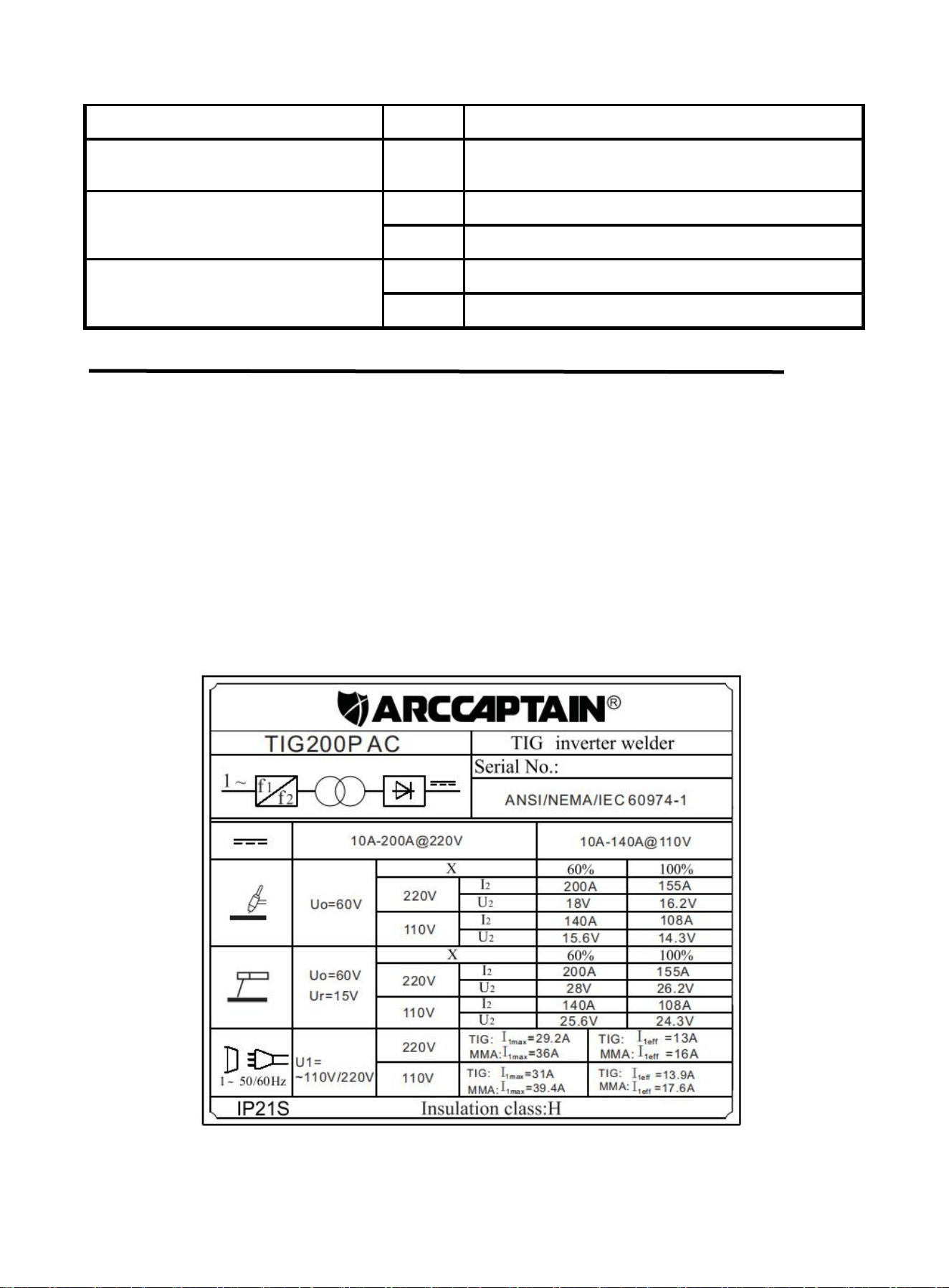
2.4 Nameplate
On the machine, there is a plate that includes all the operating specifications for your new unit. The serial
number of the product is also found on this plate.
The duty cycle rating of a welder defines how long the operator can weld and how long the welder must
rest and be cooled. Duty cycle is expressed as a percentage of 10 minutes and represents the maximum
welding time allowed. The balance of the 10-minute cycle is required for cooling.
For example, a welder has a duty cycle rating of 60% at the rated output of 200A. This means with that
machine: you can weld at 200A output for six (6) minutes out of 10 with the remaining four (4) minutes
required for cooling. The duty cycle of your new welder can be found on the data plate affixed to the
machine. It looks like the diagram below.
Figure 1
https://www.arccaptain.com/
7
3.FUNCTION
3.1Panel of TIG200P
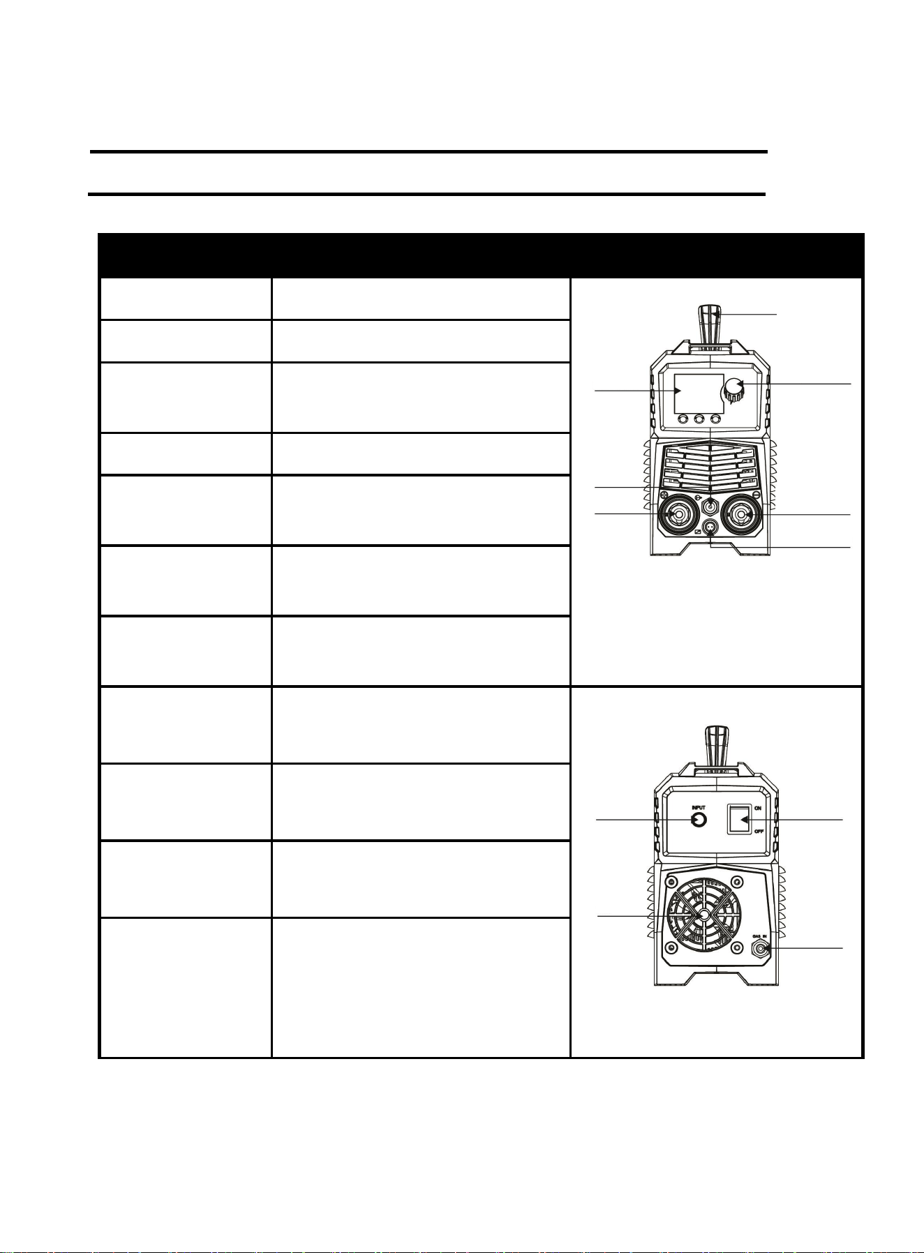
Part name Function Picture
1.Handel For translation and storage
Figure 2 Front panel of TIG200P
2.Control panel To display the welding information
3.Parameter
adjustment knob
Rotary buttons for adjusting welding
parameters
4.Gas out For conveying shielding gas
5.Output “+” terminal
To connect the Electrode
Holder/Ground Clamp
6.Output “-” terminal
To connect the Welding torch/Ground
Clamp/Electrode Holder
7.Aviation socket
To connect the switch of torch/Foot
pedal
8.Power wire For power supply input
Figure 3 Back panel of TIG200P
9.Cooling fan
For heat dissipation through forced air
cooling
10.Power switch For power supply input
11.Gas in Used to connect shielding gas
1
2
4
5
3
6
7
8
9
10
11
https://www.arccaptain.com/
8
3.2 Panel functions of TIG200P
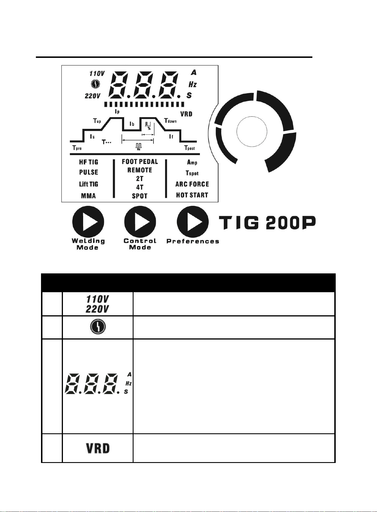
Figure 4 digital panel
No. Part name Function
1
The input voltage is AC110V when indicator is on.
The input voltage is AC220V when indicator is on.
2
When the indicator is on, it indicates that the welder is in
overcurrent protection and has stopped output
3
The table header shows the specific value of the parameters;
"A" is current unit indicator. The indicator will flash when there is
current;
"S" is time unit indicator. The indicator will be on when the time is
displayed;
"Hz" is frequency unit indicator. The indicator will be on when the
frequency is displayed;
An error code is displayed when the product is abnormal.
4
VRD function indicator.When the indicator is on, it indicates the
VRD function is enabled.
https://www.arccaptain.com/
9
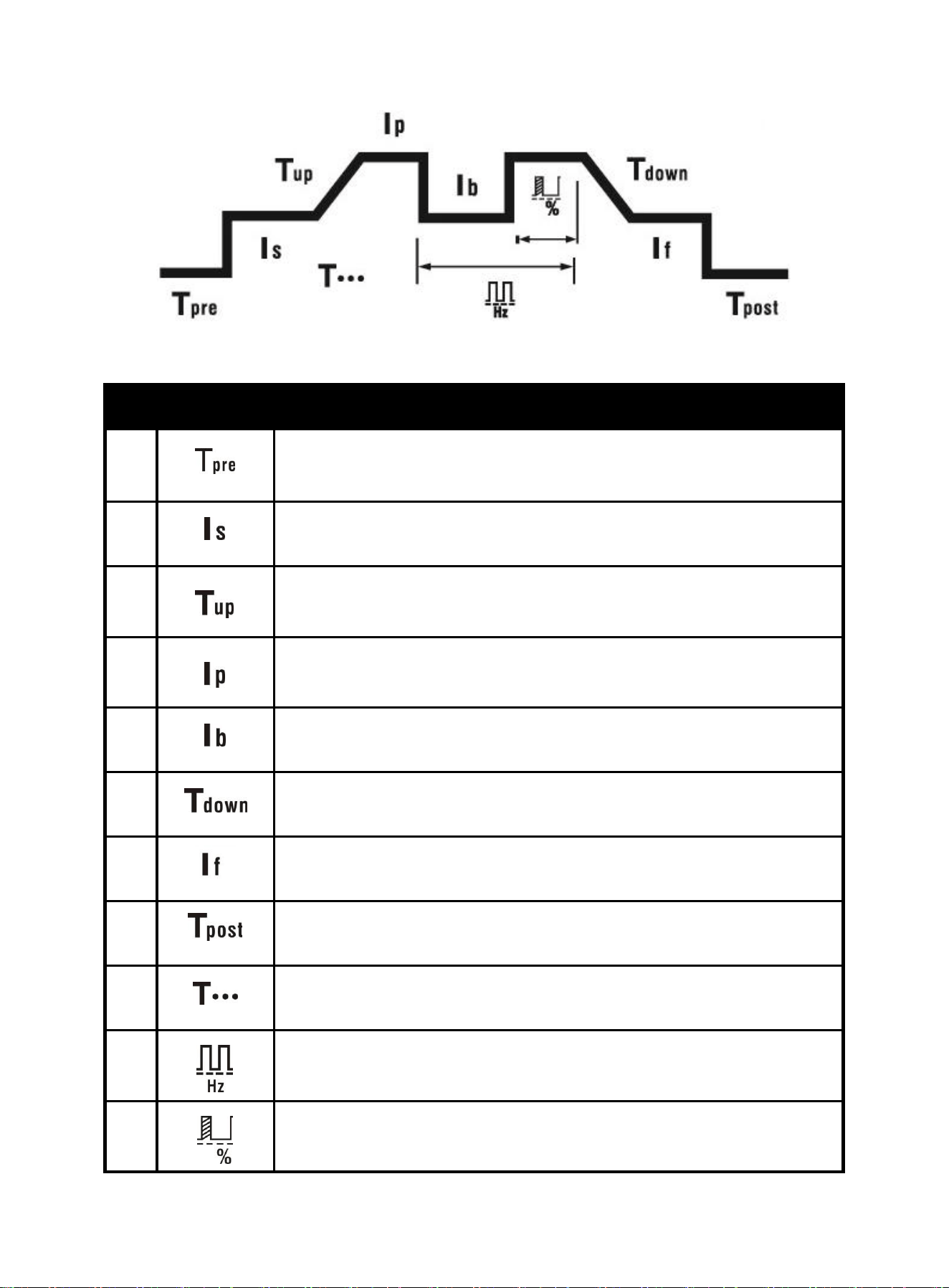
Figure 5
No. Part name Function
1
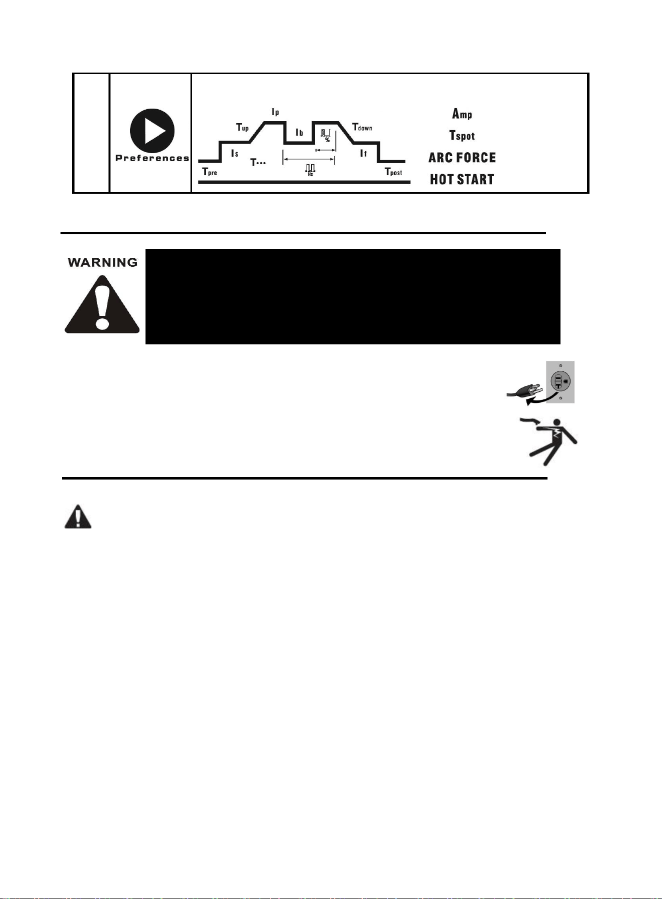
Pre-flow time indicator. When the indicator is on, it indicates the pre-flow
protection time
2
Initial current indicator. When the indicator is on, it indicates the initial
current
3
Up-slope time indicator. When the indicator is on, it indicates the time until
the initial current reaches the peak current
4
Peak current indicator. When the indicator is on, it indicates the welding
current
5
Base current indicator. When the indicator is on, it indicates the pulse base
current
6
Down-slope time indicator. When the indicator is on, it indicates the time
until the peak current drops to the finish current
7
Finish current indicator. When the indicator is on, it indicates the finish
current
8
Post-flow time indicator. When the indicator is on, it indicates the post-flow
time
9
Spot welding time indicator. When the indicator is on, it indicates the spot
welding time
10
Pulse frequency indicator. When the indicator is on, it indicates the pulse
frequency
11
1) Duty-cycle indicator. When the indicator is on, it indicates the ratio of
peak current time to pulse period
https://www.arccaptain.com/
10
No. Part name Function
1
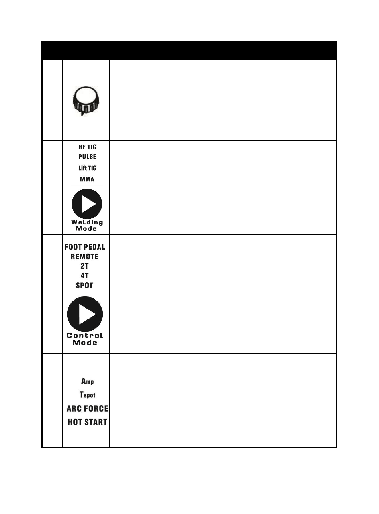
Parameter adjustment knob
1. Rotate the adjustment knob to adjust the parameter.
2. Rotate the knob clockwise to increase the value, and counterclockwise
to decrease the value.
3. When the knob is rotated, the adjustment is displayed in the parameter
display area. The progress bar on the left side of the knob is adjusted
proportionally with the value.
2
1. Press the Welding Mode button to switch the welding mode.
2. HF TIG indicator.When the indicator is on, it indicates the HF TIG mode
is selected.
3. PULSE indicator. When the indicator is on, it indicates the Pulse TIG
mode is selected.
4. Lift TIG indicator.When the indicator is on, it indicates the Lift TIG mode
is selected.
5. MMA indicator. When the indicator is on, it indicates the MMA mode is
selected.
3
1. Press the Control Mode button to switch the control mode.
2. FOOT PEDAL indicator.When the indicator is on, it indicates the Foot
pedal mode is selected.
3. REMOTE indicator. When the indicator is on, it indicates the analog TIG
torch remote mode is selected.
4. 2T indicator.If the indicator is on, it indicates the machine is in 2T
welding mode.
5. 4T indicator. If the indicator is on, it indicates the machine is in 4T
welding mode.
6. SPOT indicator.If the indicator is on, it indicates the machine is in spot
welding mode.
4
1. Amp indicator. When the indicator is on, it indicates the welding current.
2. Tspot indicator. When the indicator is on, it indicates the spot welding
time.
3. ARC FORCE indicator. When the indicator is on, it indicates the MMA
arc-force current.
4. HOT START indicator. When the indicator is on, it indicates the MMA
hot start current.
https://www.arccaptain.com/
11
The following operation requires sufficient professional knowledge on electric
aspect and comprehensive safety knowledge. Operators should be holders of
valid qualification certificates which can prove their skills and knowledge. Make
sure the input cable of the machine is disconnected from the electricity utility
before uncovering the welding machine.
4.INSTALLATION AND CONNECTION
Note:
Turn off the power supply switch before any electric connection operation.
The housing protection grade of this machine is IP21S, so do not use it in rain.
Place the Welder on a level surface that can bear its weight near the work area.
4.1 Installation requirements
Environment requirements
Please pay attention to the following when choosing installation site:
Please avoid environment which contains too much dusts or metal powder.
Avoid installation in area which is with corrosive or explosive gases.
Ambient temperature should be within-10℃~+40℃;Please reinforce radiation or lessen
power machine operation when temperature is over 40℃.
Installation should be carried out in dry environment with humidity less than 90%.
Avoid welding in the open air with strong wind; please install windscreen if necessary, or else
welding performances may be affected.
Please consult and confirm in advance if there is any special installation requirement.
If the Welding power is paced on tilt plane, pay attention to avoid it topple over.
The Welding power is forbidden to use thaw pipe.
5
Press the Preferences mode button to switch the following parameters..
https://www.arccaptain.com/
12
Installation space requirements
Distance between welder and wall should be more than 20cm(7.87”); distance between two abreast
welders should be more than 30cm(11.82”). You may refer to the below suggested reserved installation
space to confirm the installation position.
Department
Front Left Side Right Side Back
Reserved Space ≥20cm/7.87" ≥20cm/7.87" ≥20cm/7.87" ≥20cm/7.87"
4.2 TIG Welder Cable Connection
Description
Picture
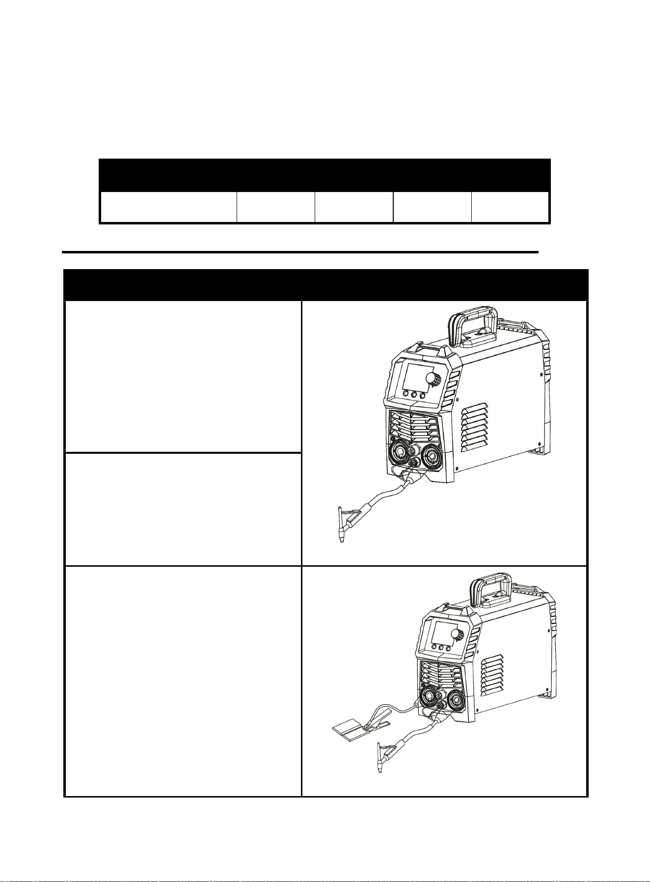
1.Please connect TIG torch correctly
according to Figure 6. Connect the gas &
electric connector of the TIG torch to the
corresponding connector on the machine
panel, and tighten it clockwise.
NOTE: Make sure the link is partially
tightened.
Figure 6
2.Connect the aviation plug on the TIG torch
to the corresponding socket on the machine
panel. (Figure 6.)
NOTE: Make sure the link is partially
tightened.
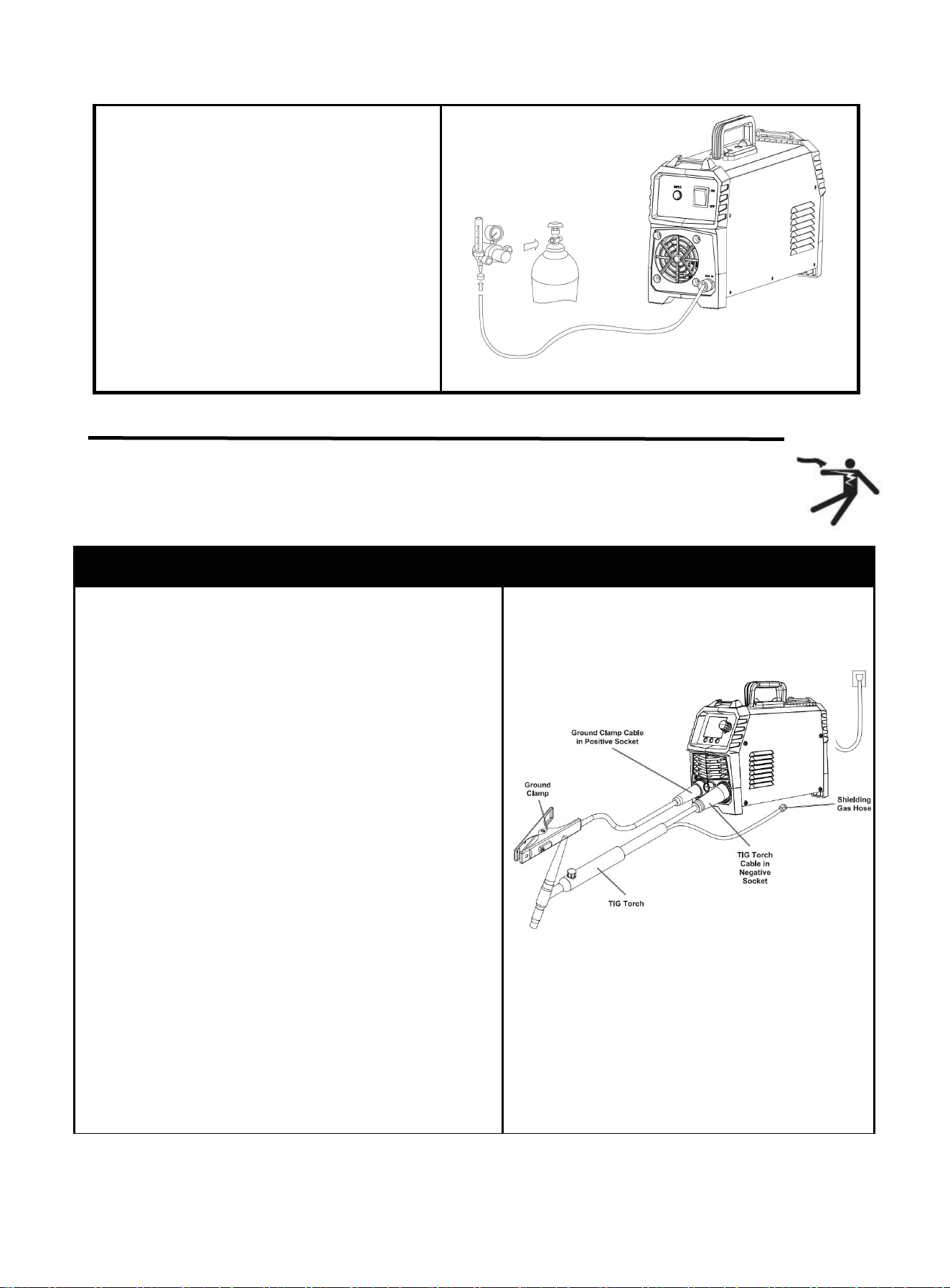
3.Insert the quick plug on the earth cable
into the “+” quick socket on the machine
panel, and tighten it clockwise. Clamp the
workpiece with the earth clamp at the other
end of the earth cable. (Figure 7.)
NOTE: Make sure the link is partially
tightened.
Figure 7 Installation of Earth cable
https://www.arccaptain.com/
13
4.3 LIFT TIG Welder Cable Connection
NOTICE: Before setting up or using this product for new function, make
sure to read the entire Important Safety Information section at the
beginning of this manual !
4.Gas connection: connect argon tube with
welder back panel’s brass mouthpiece
tightly. Air supply passage should include
argon decompressed flowmeter, gas hose;
Be sure to secure the hose connections to
avoid poor solder joint protection due to gas
leakage or air intrusion. (Figure 8)
NOTE: Make sure the link is partially
tightened.
Figure 8 Gas connection
Description
Picture
Step 1: Connect cables.
1.Insert the ground clamp cable into the positive socket
and twist it all the way clockwise to lock it in place.
NOTICE:
The ground clamp connector MUST be tightly
connected to the socket to avoid power short
circuit.
Ensure the ground clamp is connected on clean,
bare metal (not rusty or painted)
2.Plug the Lift-TIG torch cable into the negative socket
and twist it clockwise to lock it in place.
4. For instructions on connecting a shielded gas hose,
refer to the 'Connecting Shielded Gas' section on the
following page.
NOTICE:
The Lift-TIG torch cable MUST be tightly
connected to the socket to avoid power short
circuit.
Set Lift-TIG torch cable down on
nonconductive, nonflammable surface away from
any grounded objects.
Figure 9
https://www.arccaptain.com/
14
More information:
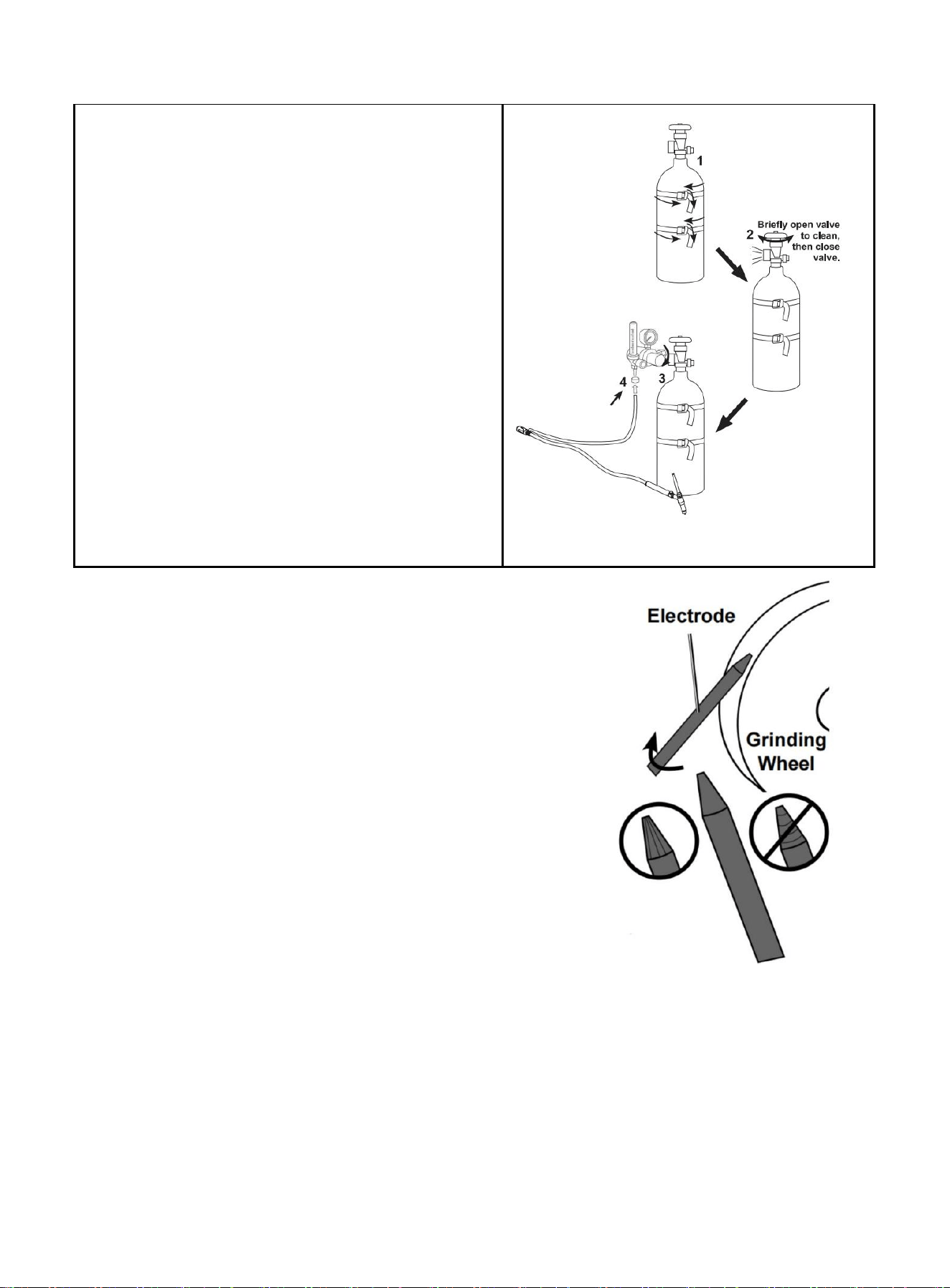
Sharpen tungsten Electrode
To avoid Electrode contamination, dedicate a fine grit grinding wheel
exclusively to Electrode grinding.
1.Shut off the welder and wait until Electrode and Torch have cooled
enough to handle.
2.Remove Back Cap to release Collet’s grip on Electrode.
3.Pull Electrode out from front of Torch. (Pulling it from rear will
damage Collet and create burrs on Electrode).
4.If Electrode has dulled or been otherwise contaminated, use pliers
or a suitable tool to grip the Electrode above the contaminated
section and snap off the end of the Electrode.
5.Lightly press Electrode tip against the surface of the grinding wheel
at an angle. Rotate Electrode tip until a blunt point is formed.
NOTE: Grinding direction must be parallel to length of Electrode.
6.The conical portion of the ideal tip will be 2-1/2 times as long as the Electrode diameter.
7.Re-insert Electrode into Collet with tip protruding 1/8"-1/4" beyond the Ceramic Nozzle, then re-tighten
the Back Cap to secure the Electrode in place.
Step 2: connect Shielding gas
1.With assistance, place a 100% Argon cylinder (not
included) onto a cabinet or cart near the welder.
Secure the cylinder in place with two straps (not
included) to prevent tipping.
2.Remove the cylinder's cap. Stand to the side of the
valve opening, then briefly open the valve to blow
dust and dirt from the valve opening. Close the
cylinder valve.
3.Locate the regulator (not included) and loosen its
valve. Thread the regulator onto the cylinder and
tighten the connection with a wrench.
4.Connect the shielding gas hose on the TIG torch
cable connector to the regulator's outlet and tighten
the connection with a wrench.
Figure 10
Figure 11
https://www.arccaptain.com/
15
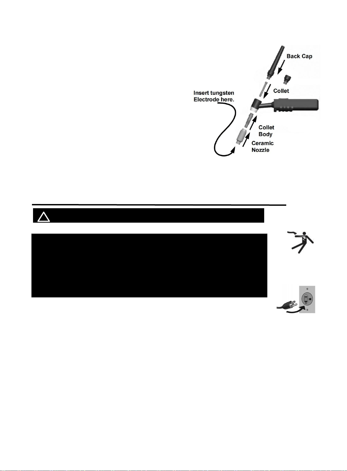
Assemble tig torch
1. Consult Settings Chart, on top of Welder, to determine
proper Tungsten Electrode size to be used with
thickness of material to be welded.
2. Match Collet and Collet Body sizes to Tungsten
Electrode size.
3. Thread Collet Body into the front of the Torch.
4. Make sure Ceramic Nozzle size is appropriate for
application.
5. Thread Ceramic Nozzle onto Collet Body.
6. Insert Collet into back of Torch and into Collet Body.
7. Insert Tungsten Electrode into Collet on front of Torch.
8. Lock Electrode in place with Back Cap. Electrode should protrude 1/8" to 1/4" beyond
the Ceramic Nozzle.
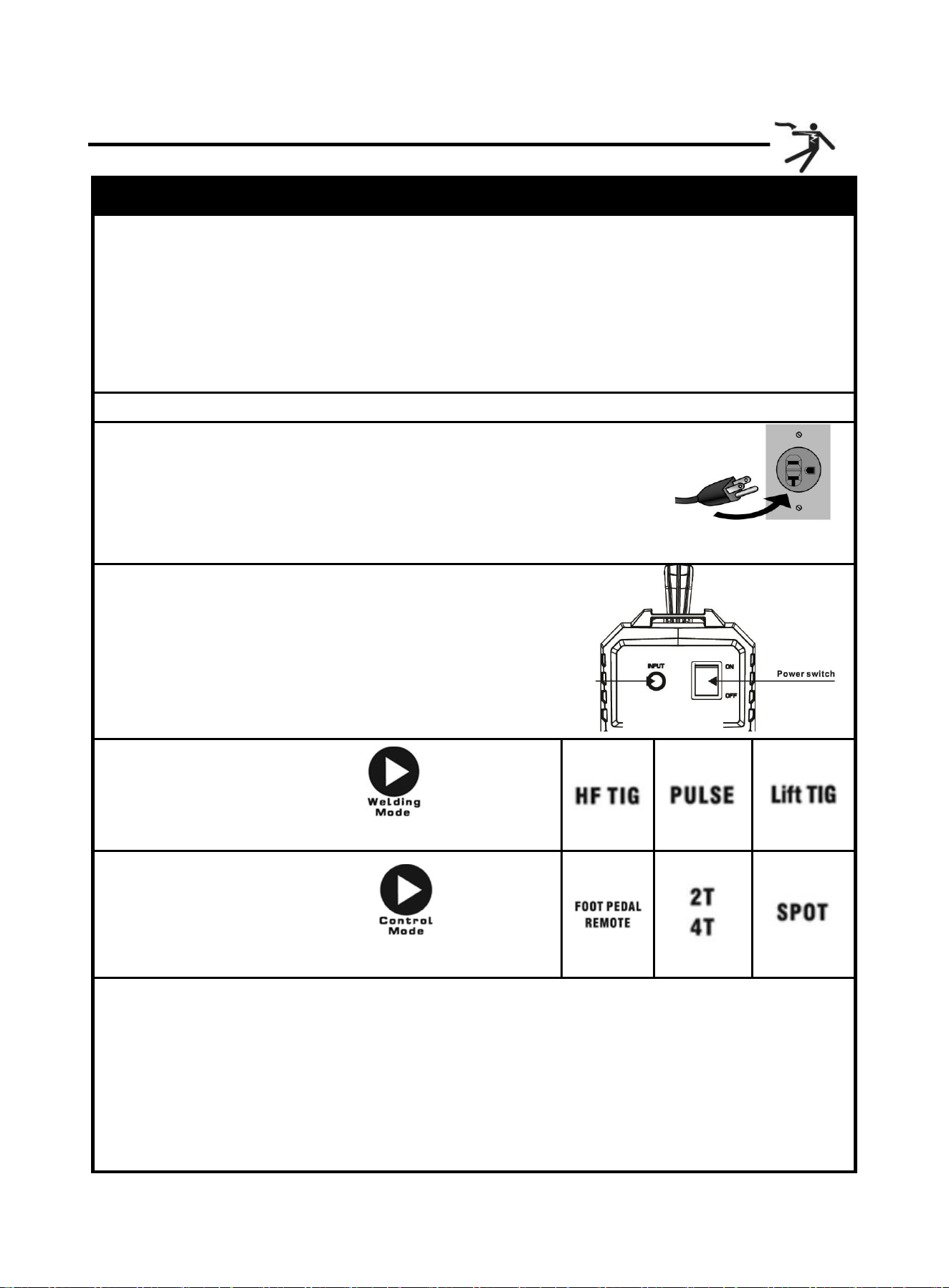
4.4 Input Power Connection
! WARINING BE WARE OF ELECTRIC SHOCK!
The TIG200P operates with a 110V or 220V power supply.
Turn the Power Switch to the OFF position, then plug the Welder into a properly
grounded 220V receptacle that matches the plug. Use the included 110V power adaptor if plugging
the Welder into a 110V receptacle.
Plug the Power Cord into a properly grounded. Set Electrode Holder down on nonconductive,
nonflammable surface away from any grounded objects. And then turn the Power Switch ON.
NOTE:
For optimal performance, connect the TIG200P to a 50A branch circuit. If connected to a
circuit with lower capacity, expect reduced welding current and duty cycle. The circuit must
be equipped over 50A with delayed action-type circuit breaker or fuse.
NOTICE: The following steps require applying power to the Welder
with the cover open.
To prevent serious injury from fire or electric shock:
1. DO NOT touch anything, especially not the ground clamp, with the
gun or welding wire or an arc will be ignited.
2. DO NOT touch internal Welder Components while it is plugged in.
Figure 12
https://www.arccaptain.com/
16
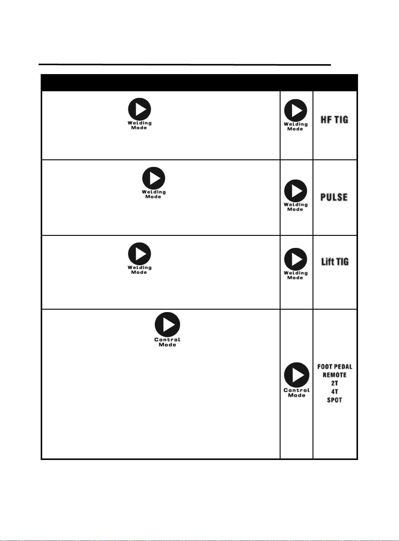
4.5 TIG Welder Operation
Operation step
1.Open gas cylinder’s valve all the way.
NOTE: TO PREVENT DEATH FROM ASPHYXIATION:
Do not open gas without proper ventilation. Fix gas leaks immediately. Shielding gas can
displace air and cause rapid loss of consciousness and death. Shielding gas without carbon
dioxide can be even more hazardous because asphyxiation can start without feeling
shortness of breath.
2.Set Flow Gauge to SCFH VALUE.
3.connect power cord.
NOTE: Turn the Power Switch off before connecting Power Cord. Plug
the Power Cord into a properly grounded and rated receptacle that
matches the plug. The circuit must be equipped with delayed
action-type circuit breaker or fuses.
4.Turn the Power Switch ON.
NOTE: Set TIG Torch down on nonconductive,
nonflammable surface away from any grounded objects.
The Operation interface will light up and the Cooling fan will
rotate.
5.Press the Welding Mode button , for TIG welding
mode changeover.
6.Press the Control Mode button , for operation
mode changeover.
7.Hold TIG Torch in one hand and the TIG Rod (sold separately) in other hand. Both hands need to
wear protective gloves.
WARNING! TO PREVENT SERIOUS INJURY: Metalwork bench must be grounded when TIG
welding.
NOTE: Maintain a constant distance between the Tungsten Electrode and the workpiece: between 1
and 1.5 times the diameter of the Electrode.
Figure 14
Figure 13
https://www.arccaptain.com/

17
8.The initial settings may need to be adjusted after stopping and carefully inspecting the weld. Please
refer to 6. WELDING PARAMETERS TABLE, Proper welding takes experience.
9.When welding puddle is hot enough, tilt Torch backward about 10-15 degrees from vertical and
move it back slightly. Add TIG Rod material as needed to the front end of the weld puddle.
10.Alternate between pushing the torch/weld puddle and adding the TIG Rod material.
NOTE: Remove the TIG Rod each time the Electrode is advanced, but do not remove it from the gas
shield. This prevents oxidation from contaminating the weld.
11.When finished welding, pull Torch away from work piece until welding arc is broken, then return the
gas coverage until weld solidifies.
12.Close valve on TIG Torch and turn Right Knob to OFF to turn off power.
13.Set TIG Torch down on nonconductive, nonflammable surface away from any grounded object.
14.Turn the Power Switch OFF.
15.To prevent accidents, after use:
Allow Welder to cool down.
Remove Ground Clamp from workpiece or table.
Disconnect TIG Torch and Ground Cables.
Close gas cylinder’s valve securely, remove regulator and replace cap.
Disconnect Gas.
If Electrode has dulled or been otherwise contaminated, use pliers or a suitable tool to grip the
Electrode above the contaminated section and snap off the end of the Electrode.
https://www.arccaptain.com/
18
4.6 TIG Welding Mode
Describe Part Select
Press the Mode button , for HF-TIG welding mode changeover.
rotate the knob to adjust the current. Adjustment range is 10-200
amps.
Press the Mode button , for Pulse-TIG welding mode
changeover. rotate the knob to adjust the current. Adjustment range is
10-200 amps.
Press the Mode button , for Lift-TIG welding mode changeover.
rotate the knob to adjust the current. Adjustment range is 10-200
amps.
Press the Control Mode button to switch the control mode.
FOOT PEDAL indicator.When the indicator is on, it indicates the Foot
pedal mode is selected.
REMOTE indicator. When the indicator is on, it indicates the analog TIG
torch remote mode is selected.
2T indicator.If the indicator is on, it indicates the machine is in 2T
welding mode.
4T indicator. If the indicator is on, it indicates the machine is in 4T
welding mode.
SPOT indicator.If the indicator is on, it indicates the machine is in spot
welding mode.
https://www.arccaptain.com/
19
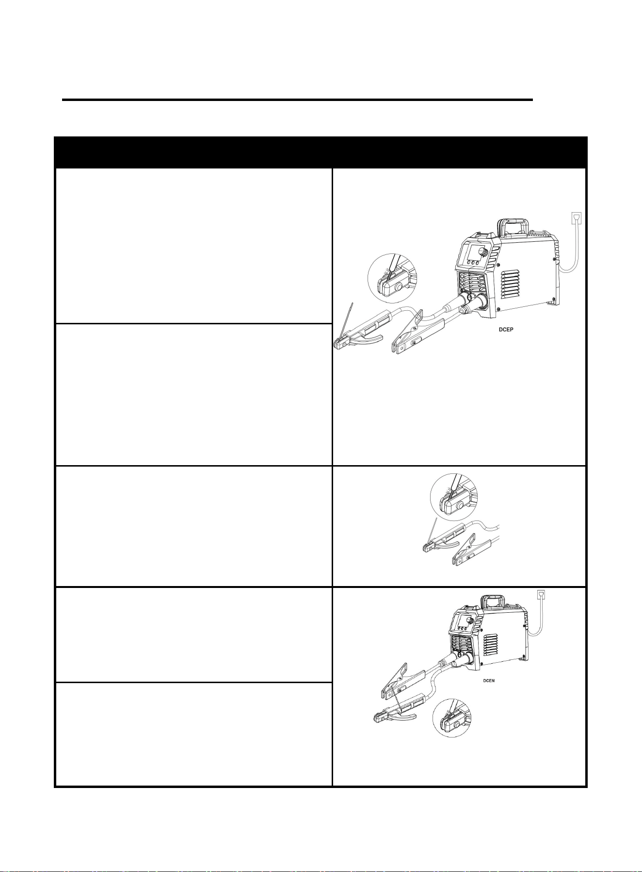
4.7 Installation for MMA function
Please install the machine strictly according to the following steps.
Description
Picture
1. Insert the cable plug with electrode holder into the
“+” socket on the front panel of the welding machine,
and tighten it clockwise.
NOTICE:
The holder connector MUST be tightly connected
to the socket to avoid power short circuit.Set
Electrode Holder down on
nonconductive,nonflammable surface away from
any grounded objects.
Figure 15 DCEP Schematic Diagram of
MMA Welding
2. Insert the cable plug with ground clamp into the“-”
socket on the front panel of the welding machine, and
tighten it clockwise.
NOTICE:
The ground clamp connector MUST be tightly
connected to the socket to avoid power short
circuit.Ensure the ground clamp is connected on
clean, bare metal.(not rusty or painted)
3. Place the bare metal end of the Stick Electrode
inside the jaws of the Electrode Holder.
NOTICE:
Ensure that the clip is on the conductive side of
the electrode. Ensure that it is securely clamped.
Figure 16
4. When you use Alkaline rods (E7018), need to
DCEP, that is connect the holder and ground clamp
as mentioned above in above 1. and 2.
Figure 17 DCEN Schematic Diagram of MMA
Welding
5. If you use Acidic rods(E6013), need to DCEN, that
is connect the holder to “-”and ground clamp to “+” .
NOTICE:
Incorrect connecting can affect welding results.
https://www.arccaptain.com/
20
4.8 MMA Welding Mode
4.9 MMA Welding Parameters Table
Note: This table is suitable for mild steel welding. For other materials, consult related materials
and welding process for reference.
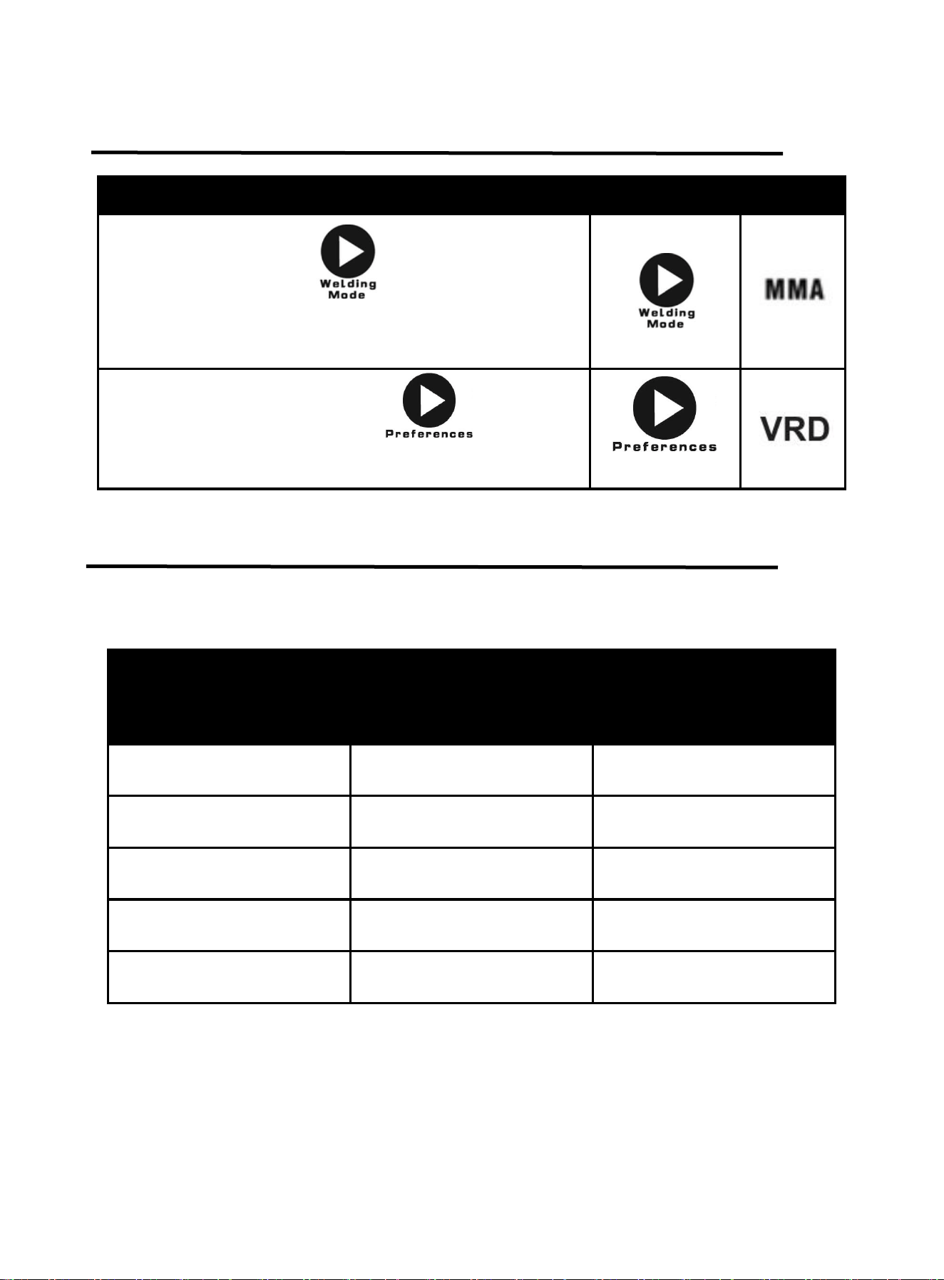
Describe Part Select
Press the Mode button , for MMA welding mode
changeover. rotate the knob to adjust the current. Adjustment
range is 10-200 amps
In MMA mode, press and hold the for 5 seconds
to turn VRD on/off. VRD is not enabled by default.
Electrode Diameter
mm(inch)
Plate thickness
mm
(inch)
Recommended Welding
Current(A)
1.6mm
1/16
1~2.5mm
0.04~0.11
30~65
2mm
2/25
2.3~4mm
0.09~0.16
49~94
2.4mm
3/32
3.5~4.5mm
0.14~0.18
78~123
3.2mm
1/8
4.8~8.3mm
0.19~0.33
99~177
4.0mm
5/32
8.6~10mm
0.34~0.39
178~200
https://www.arccaptain.com/
21
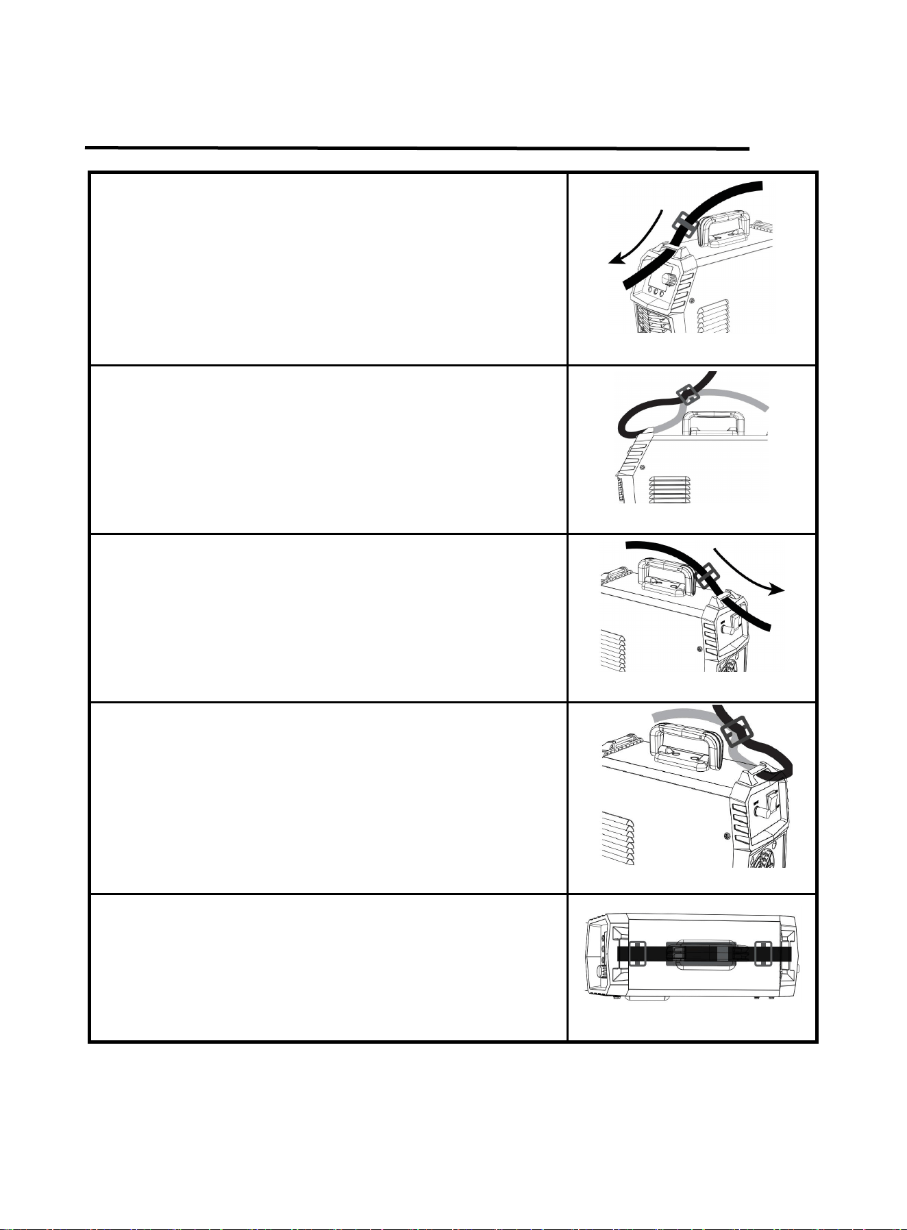
5. STRAP INSTALLATION
Step 1: Thread the strap through the strap hole in front of the
welder.
Figure 18
Step 2: Thread the strap through the nylon buckle as shown in the
diagram.
Figure 19
Step 3: Thread the strap through the strap hole in back of the
welder.
Figure 20
Step 4: Thread the strap through the nylon buckle as shown in the
diagram.
Figure 21
Step 5: The strap installation is complete.
Figure 22
https://www.arccaptain.com/
22
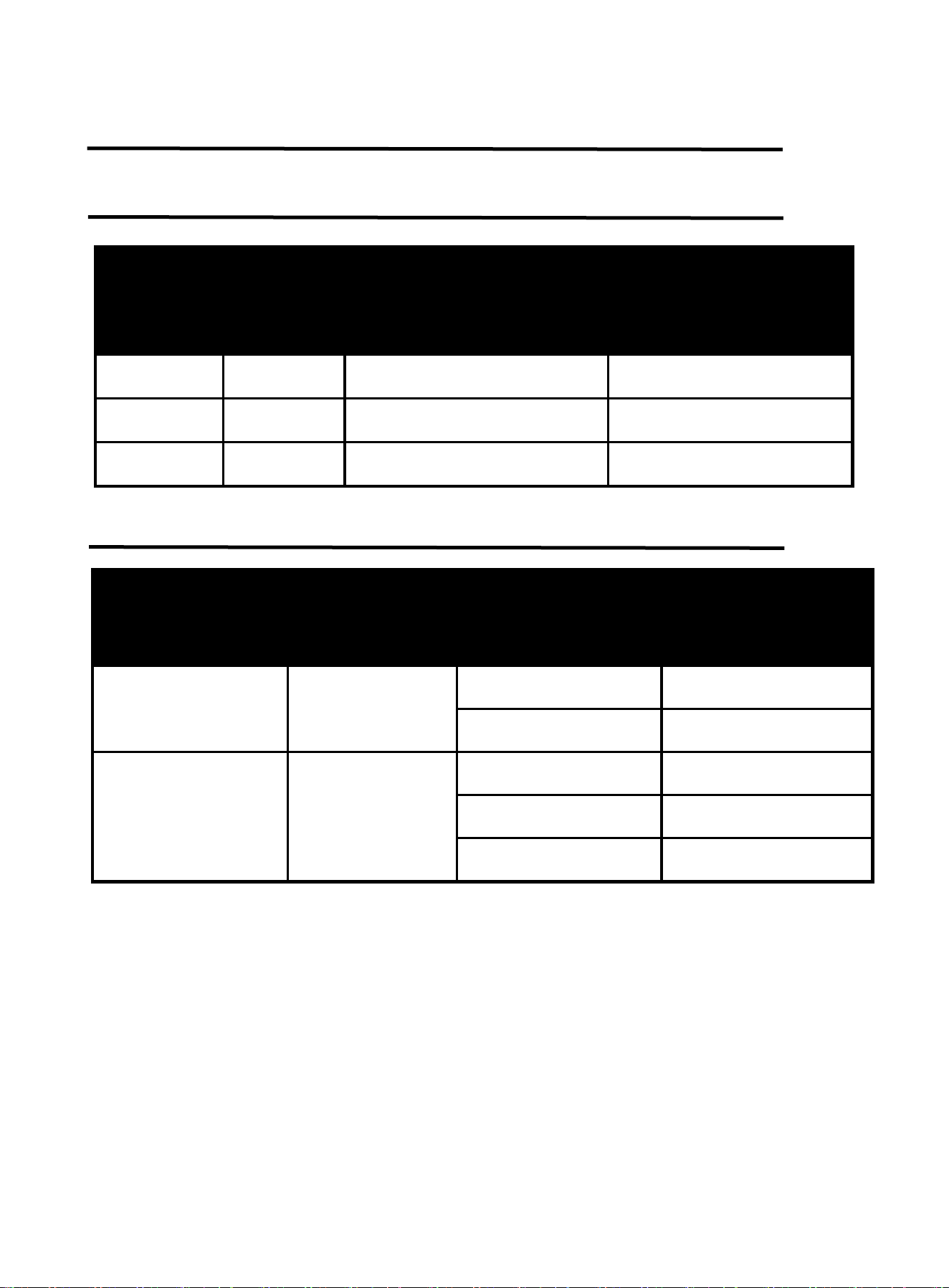
6. WELDING PARAMETERS TABLE
6.1 Parameters for TIG electrode
Electrode diameter
Amperage range on DCEN
Straight polarity
Amperage range on DCEP
Straight polarity
mm inch
1
.040" 15-80 /
1.6 1/16" 70-150 10-20
2.4 3/32" 150-200 15-30
6.2 Parameters for TIG welding on stainless steel sheet
Electrode diameter
mm
(inch)
Plate thickness
mm
(inch)
Welding current(A) Gas flow(L/min)
1~2mm
(0.040”-5/64”)
1~3mm
(0.040”- 0.12”)
50 5
50~80 6
2~4mm
(5/64”-5/32 “)
3~6mm
(0.12”-0.24”)
80~120 7
121~160 8
161~200 9
https://www.arccaptain.com/

23
6.3 Parameters for TIG welding
Plate
thickness
mm (inch)
Welding
layers
Electrode
diameter mm
(inch)
Wire diameter
mm (inch)
Welding
current(
A)
Gas flow (L/min)
Nozzle
diameter
mm (inch)
Square
groove
Single V
groove
with root
face
Double V
groove
with root
face
0.5(0.020") 1 1.5(0.059") 1 (0.040") 30~50 8~10 6~8 14~16 10(0.393")
1 (0.040") 1 2(0.079")
1.0~2.0
(0.040"-0.079")
40~60 8~10 6~8 14~16 10(0.393")
1.5(0.060") 1 2(0.079")
1.0~2.0
(0.040"-0.079")
60~80 10~12 8`10 14~16
10~12
(0.393"-0.472)
2(0.079") 1
2.0~3.0
(0.079"-0.118")
1.0~2.0
(0.040"-0.079")
80~110 12~14 10~12 16~20
12~14
(0.472"-0.551")
2.5(0.098") 1
2.0~3.0
(0.079"-0.118")
2 (0.079") 110~120 12~14 10~12 16~20
12~14
(0.472"-0.551")
3(0.118") 1~2 3(0.12")
2.0~3.0
(0.079"-0.118")
120~140 12~14 10~12 16~20
14~18
(0.551"-0.708")
4(0.157") 2
3.0~4.0
(0.12~5/32")
2.0~3.0
(0.079"-0.118")
130~150 14~16 12~14 20~25
18~20
(0.708"-0.787")
5(0.197") 2~3 4.0(5/32”) 3(0.118") 130~150 14~16 12~14 20~25
18~20
(0.708"-0.787")
6(0.236") 2~3 4.0(5/32”)
3.0~4.0
(0.118"-5/32”)
140~180 14~16 12~14 25~28
18~20
(0.708"-0.787")
7(0.257") 2~3 4.0(5/32”)
3.0~4.0
(0.118"-5/32”)
140~180 14~16 12~14 25~28
20~22
(0.787"-0.866")
8(0.315") 3~4 4.0(5/32”)
3.0~4.0
(0.118"-5/32”)
140~180 14~16 12~14 25~28
20~22
(0.787"-0.866")
10(0.394") 4~6 4.0(5/32”)
3.0~4.0
(0.118"-5/32”)
160~200 14~16 12~14 25~28
20~22
(0.787"-0.866")
20(0.787") 12 4.0(5/32”) 4(5/32”) 200~240 12~14 10~12 20 18(0.708")
22(0.866") 12 4.0(5/32”)
4.0~5.0
(5/32”-0.197")
230~250 15~18 18~20 18~20 20(0.787")
25(0.984") 15~16 4.0(5/32”)
3.0~4.0
(0.118"-5/32”)
200~220 16~18 20~26 26~30 22(0.866")
30(1.181") 17~18 4.0(5/32”)
3.0~4.0
(0.118"-5/32”)
200~220 16~18 20~26 26~30 22(0.866")
https://www.arccaptain.com/

24
7. BASIC KNOWLEDGE OF TIG WELDING
7.1 TIG Overview and Characteristics
TIG is a gas shielded arc welding that uses argon as the protective gas. TIG welding process is as
shown in the figure. It uses the argon gas flow ejected from the nozzle of the welding gun to form a tightly
closed protector in the arc area to isolate the metal molten pool from the air, so as to prevent air intrusion.
Besides, it uses the heat generated by the arc to melt the filler wire and base metal, and the liquid metal
molten pool will form weld after cooling.
Figure 23 TIG diagram
Argon is an inert-gas and does not react chemically with metal, so it will not burn the alloy elements
in the metal being welded and can fully protect the metal molten pool from oxidation. Moreover, argon is
insoluble in liquid metal at high temperature, so it is not easy to cause gas pores in the weld. Therefore,
argon can provide effective and reliable protection effect, thus obtaining higher welding quality.
7.2 TIG Characteristics
Compared with other stud arc welding methods, TIG enjoys the following characteristics:
Argon has excellent protection performance, and there is no need to prepare corresponding flux
during welding. It is basically a simple process of metal melting and crystallization, which can obtain
relatively pure and high-quality welds.
Because the arc is compressed and cooled by the argon gas flow, the heat of arc is concentrated, and
the temperature of the argon arc is very high. Therefore, the heat-affected zone is very narrow,
the welding deformation and stress are small, and the crack tendency is small. It is especially suitable
for welding of thin plates.
TIG is open arc welding, which is convenient to operate and observe, making it easy to realize the
mechanization and automation of the welding process. In addition, welding in various
spatial positions can be performed under certain conditions.
Molten pool
Filler wire
Gas
Nozzle
Tungsten
Weld
https://www.arccaptain.com/
25
TIG supports a wide range of weldable materials, including almost all metal materials, especially
suitable for welding chemically active metals and alloys.
It is generally used for welding aluminum, titanium, copper and their low alloy steels, stainless steels
and heat resistant steels, etc.
Because of these outstanding characteristics of TIG, with the increasing product structure of non-ferrous
metals, high alloy steels and rare metals, and unattainable welding quality requirements by the common
gas welding or arc welding methods, TIG welding is more and more widely used.
7.3 TIG Welding Gun
The TIG welding gun is used to clamp the electrode, conduct electricity and transport argon gas flow,
which are controlled by the start and stop buttons on the holder. The welding gun comprises three types,
the maximum welding current for small type is 100A, and for large type is 400-600A, all adopting water
cooling. The welding gun body is pressed by nylon, featuring with light weight, small volume, good
insulation and heat resistance.
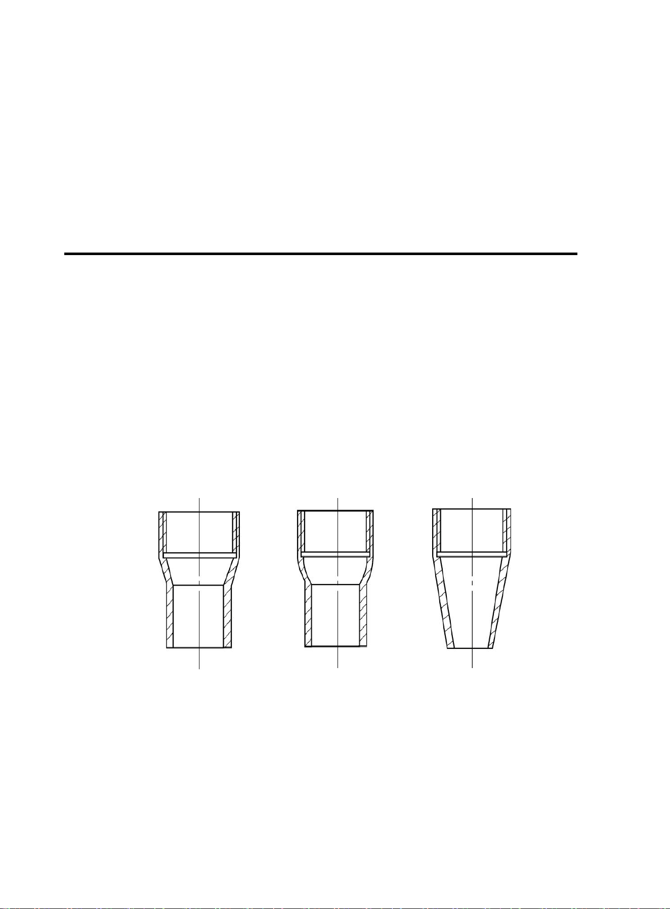
The welding gun nozzle serves as an important component that determines the gas shield
protection performance, and the common nozzle shapes are as shown in the figure. The cylindrical
nozzle with conical or spherical tail has the best protection effect, as the argon gas flow rate is uniform,
which makes it easy to maintain laminar flow. The conical nozzle has poorer protection effect because of
the rapid argon airflow speed, but it is easy to operate and has good visibility of molten pool, and is often
used in welding.
Figure 24 Welding gun nozzle diagram
(a) Cylinder mixed with
conical shape
(b) Cylinder mixed with
spherical shape
(c) Cone
https://www.arccaptain.com/

26
7.4 TIG Process
Cleaning before welding
Before carrying out TIG, the joint of the welded material and the welding wire must be cleaned to
remove the oxide film and oil stains on the metal surface to ensure the quality of the weld. The cleaning
methods include mechanical cleaning, chemical cleaning and chemical mechanical cleaning.
Mechanical cleaning: This method is simple and effective. It is suitable for cleaning weldments
with large size and long welding cycle. Usually use a stainless steel wire brush and other tools
with a small diameter for polishing, or use a spatula to remove the surface oxide film to expose
the metal luster of the welding part, and then use an organic solvent to remove oil stains to
clean the vicinity of the weldment joints.
Chemical cleaning: This method is often used for cleaning filler wire and small weldments.
Compared with the mechanical cleaning method, this method has the characteristics of high
cleaning efficiency, stable and uniform quality, and long retention time. The chemical solution
and process used in the chemical cleaning should be determined according to the material to
be welded and welding requirements.
Chemical mechanical cleaning: First use chemical cleaning, and then use mechanical cleaning
at the welding parts before welding. This combined cleaning method is suitable for weldments
with higher quality requirements.
Gas protection effect
Argon is an ideal protective gas, with a boiling point of -186℃, between the boiling points of oxygen
and helium. It is a by-product of fractional distillation of liquid air in an oxygen plant to produce oxygen. In
China, bottled argon is used for welding, and its filling pressure is 15MPa at room temperature. The
cylinder is painted gray and marked with the word "Argon". The chemical composition requirements of
pure argon are: Ar ≥ 99.99%; He ≤ 0.01%; O2 ≤ 0.0015%; H2 ≤ 0.0005%; total carbon content ≤ 0.001%;
moisture ≤ 30mg/m3.
It is beneficial to protect welding arc and reduce the consumption of protective gas during flat
position welding. Argon is a chemically inactive gas and does not chemically react with metals even at
high temperatures, so there is no oxidation and burning of alloying elements and a series of problems
caused by it. Argon is also insoluble in liquid metal, so it does not cause gas pores. Argon is a
monatomic gas that exists in atomic state and has no molecular decomposition or atomic endothermic
phenomena at high temperatures. Argon has small specific heat capacity and heat conduction capacity,
that is, small heat absorption and less heat transfer. Therefore, the heat in the arc is not easy to lose,
making the welding arc combustion stable and the heat concentrated, which are conducive to welding.
https://www.arccaptain.com/

27
The disadvantage of argon is its high ionization potential. When the arc space is filled with argon, it
is difficult to ignite the arc, but the arc is very stable once ignited.
In the process of welding, the protection effect of argon is affected by many technological factors.
Therefore, it is necessary to pay attention to the effective protection of argon during TIG welding to
prevent interference and damage to the protection effect of argon; otherwise, it is difficult to obtain
required welding quality.
The welding technology factors affecting the argon protection effect include gas flow rate, nozzle shape
and diameter, distance between nozzle and weldment, welding speed, welding joint form, etc., which
should be considered comprehensively and selected correctly.
The quality of the argon protection effect is often evaluated by the welding spot test method by
measuring the range of effective argon protection zone. For example, use AC manual tungsten electrode
TIG to conduct spot welding on the aluminum plate, and the welding process conditions remain the
same during welding; after striking arc, hold the welding gun for 5-10s before turning off the power. At
this time, a melting point will be left on the aluminum plate. The "cathode crushing" around the welding
spot will remove the oxide film on the surface of the aluminum plate, and a grayish-white area with
metallic luster will appear. This part where the oxide film is removed is the effective argon protection
zone, as shown in the figure. The larger the diameter of the effective protection zone, the better the
protection effect.
Figure 25 Argon protection effect diagram
In addition, the argon protection effect can be evaluated by directly observing the color of the weld
face. Taking welding on stainless steels as an example, if the weld metal surface is silvery white or
golden yellow, it means that the protection effect is good; if the color is grey or black, it means that the
protection effect is bad.
Effective protection zone
Meltin
g
zone
Oxidation zone
(a) Good protection effect
(b) Bad protection effect
https://www.arccaptain.com/

28
7.5 Welding Parameters
The gas protection effect, welding process stability and weld quality of TIG are directly related to
welding parameters. Therefore, reasonable selection of welding parameters is an important guarantee
for obtaining high-quality welded joints.
The welding parameters for TIG include: current type and polarity, tungsten electrode diameter, welding
current, argon flow, welding speed and process factors, etc.
Current type and polarity: The current type and polarity of TIG should be selected according to the
material to be welded and the operation method.
Tungsten electrode diameter: It is mainly selected according to the thickness of the weldment. In
addition, when the thickness of the material to be welded is equal, the allowable current of the
tungsten electrode is different due to the different types and polarities of the current used, so the
diameter of the tungsten electrode used is also different. If the diameter of the tungsten electrode is
not selected properly, it will cause unstable arc, severe burnout and tungsten inclusion in the weld.
Welding current: After the diameter of the tungsten electrode is selected, select the applicable welding
current. Too large or too small welding current will cause poor weld formation or welding defects.
Argon flow: It is mainly selected according to the tungsten electrode diameter and the nozzle diameter.
For nozzles with a certain aperture, the selected argon flow rate should be appropriate.
If the flow rate is too large, the gas flow rate will increase, and it will be difficult to maintain a stable
laminar flow, which is not good for the protection of the welding zone. Besides, it will take away a lot
of heat from the arc zone, which will affect the stable combustion of the arc. However, if the flow rate
is too small, it is easy to be interfered by the outside air flow, so as to reduce the argon protection
effect. Usually the flow of argon is in the range of 3-20L/min.
Welding speed: Under certain conditions of tungsten electrode diameter, welding current and argon
gas flow, too fast welding speed will cause the shielding gas flow to deviate from the tungsten
electrode and the molten pool, thereby affecting the argon protection effect. Moreover, the welding
speed significantly affects the shape of the weld. Therefore, an appropriate welding speed should
be selected.
Process factors: Mainly include the shape and diameter of the nozzle, the distance from the nozzle to
the weldment, the length of the tungsten electrode, the diameter of the filler wire, etc. These
process factors do not change much, but they have different degrees of influence on the welding
process and argon protection effect. Therefore, they should be selected according to specific
welding requirements.
Generally, the nozzle diameter can be selected within 5-20 mm; the distance from the nozzle to the
weldment shall not exceed 15 mm; the length of tungsten electrode out of the nozzle shall be 3-4
mm; and the diameter of filler wire shall be selected according to the thickness of weldment.
https://www.arccaptain.com/

29
7.6 General Requirements of TIG
Control requirements of gas: It is required that the gas is supplied first and exhausted last. Argon is an
inert-gas which is easy to be broken down. First fill argon between the workpiece and the electrode
needle, which is conducive to arc starting; after welding, keeping on supplying argon can prevent
the workpiece from oxidation due to rapid cooling and ensure good welding effect.
Current manual switch control requirements: When the manual switch is pressed, the current is
delayed compared to the gas. After the manual switch is turned off (after the welding is completed),
and the gas supply current is cut off first according to the requirements.
High-voltage generation and control requirements: TIG adopts the high-voltage arc starting mode,
which requires to have high voltage when arcing, and no high voltage after arcing.
Interference protection requirements: High frequency is accompanied by high voltage of arcing in TIG,
which causes serious interference to the whole circuit and requires the circuit to have good
anti-interference ability.
8. BASIC KNOWLEDGE OF MMA
Manual metal arc welding, MMA for short, is an arc welding mode by manually operating electrode.
Equipment for MMA is simple, convenient and flexible to operate, and with high adaptability. MMA is
applied to various metal materials with thickness more than 0.08inch and various structures, in particular
to weldment with complex structure and shape, short weld joint or bending shape, as well as weld joints
in various spatial locations.
8.1 Welding Process Of MMA
Connect the two output terminals of the welder to the weldment and electrode holder respectively,
and then clamp the electrode by the electrode holder. When welding, arc is ignited between the
electrode and the weldment, and the end of the electrode and part of the weldment are fused to form a
weld crater under the high-temperature arc. The weld crater is quickly cooled and condensed to form
weld joint which can firmly connect two separate pieces of weldement as a whole. The coating of the
electrode is fused to produce slag to cover the weld crater. The cooled slag can form slag crust to protect
the weld joint. The slag crust is removed at last, and the joint welding is finished.
https://www.arccaptain.com/
30
8.2 Tools For MMA
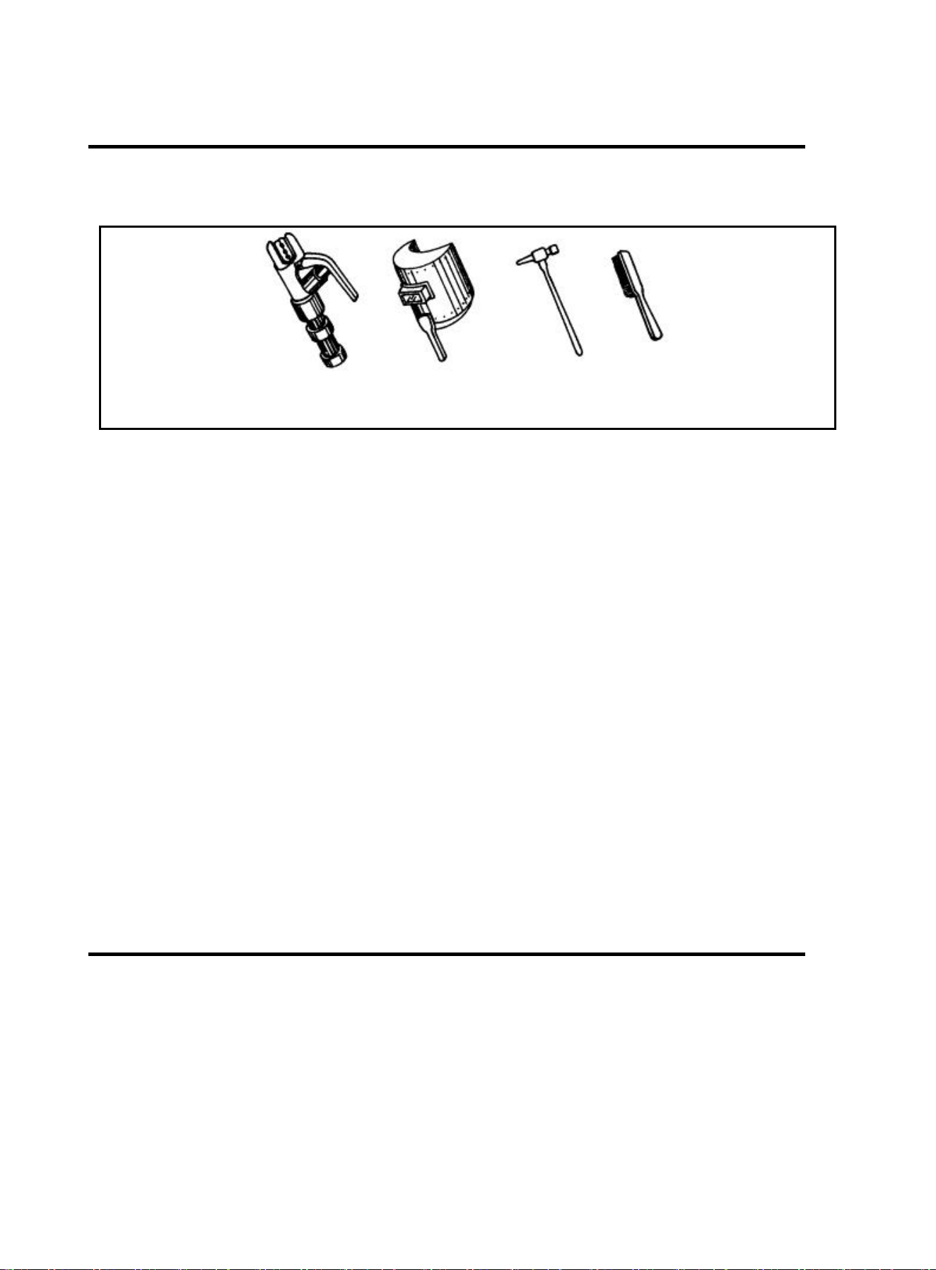
Common tools for MMA include electrode holder, welding mask, slag hammer, wire brush (see
Figure 26), welding cable and labor protection supplies.
a) electrode holder b) welding mask c) slag hammer d) wire brush
Figure 26 Tools for MMA
Electrode holder: a tool for clamping electrode and conducting current, mainly including 300A type
and 500A type.
Welding mask: a shielding tool for protecting eyes and face from injuring due to arc and spatter,
including handholding type and helmet type. Colored chemical glass is installed on the viewing
window of the mask to filter ultraviolet ray and infrared ray. Arc burning condition and weld crater
condition can be observed from the viewing window during arc burning. Thus, welding can be
carried out by operators conveniently.
Slag hammer (peen hammer): for the use of removing slag crust on the surface of weld joint.
Wire brush: for the use of removing dirt and rust at the joints of the weldment before welding, as well
as cleaning the surface of weld joint and the spatter after welding.
Welding cable: generally cables formed from many fine copper wires. Both YHH type arc welding
rubber sleeve cable and THHR type arc welding rubber sleeve extra-flexible cable can be used.
Electrode holder and welding machine are connected via a cable, and this cable is named as
welding cable (live wire). Welding machine and workpiece are connected via another cable (earth
wire). The electrode holder is covered with insulating material performing insulation and heat
insulating.
8.3 Basic Operation Of MMA
Welding joint cleaning
Rust and greasy dirt at the joint should be removed completely before welding in order to implement arc
igniting and arc stabilizing conveniently as well as ensure the quality of weld joint. Wire brush can be
used for condition with low requirement on dust removal; grinding wheel can be used for condition with
high requirement on dust removal.
https://www.arccaptain.com/
31
Posture in operating
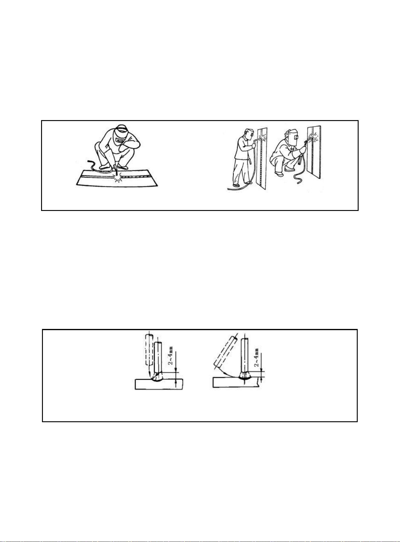
Take flat welding of butt joint and T-shaped joint from left to right as an example. (See Figure 27) The
operator should stand at the right side of the working direction of weld joint with mask in the left hand and
electrode holder in the right hand. The left elbow of the operator should be put on his left knee to prevent
his upper body from following downwards, and his arm should be separated from the costal part so as to
stretch out freely.
`
a) flat welding b) vertical welding
Figure 27 Posture in welding
Arc Igniting
Arc igniting is the process for producing stable arc between electrode and weldment in order to heat
them to implement welding. Common arc ignition mode includes scraping mode and striking mode. (See
Figure 28) During welding, touch the surface of the weldment with the end of the electrode by scraping
or light striking to form short circuit, and then quickly lift the electrode 0.08-0.16inch away to ignite arc. If
arc ignition fails, it is probably because there is coating at the end of the electrode, which affects the
electric conduction. In this case, the operator can strongly knock the electrode to remove the insulation
material until the metal surface of the core wire can be seen.
a)striking mode b) scraping mode
Figure 28 Arc ignition modes
Tack weld
For fixing the relative positions of the two pieces of weldment and welding conveniently, 1.2-1.6inch
short weld joints are welded every certain distance in order to fix the relative positions of the weldment
during welding assembly. This process is named as tack weld.
https://www.arccaptain.com/
32
Electrode manipulation
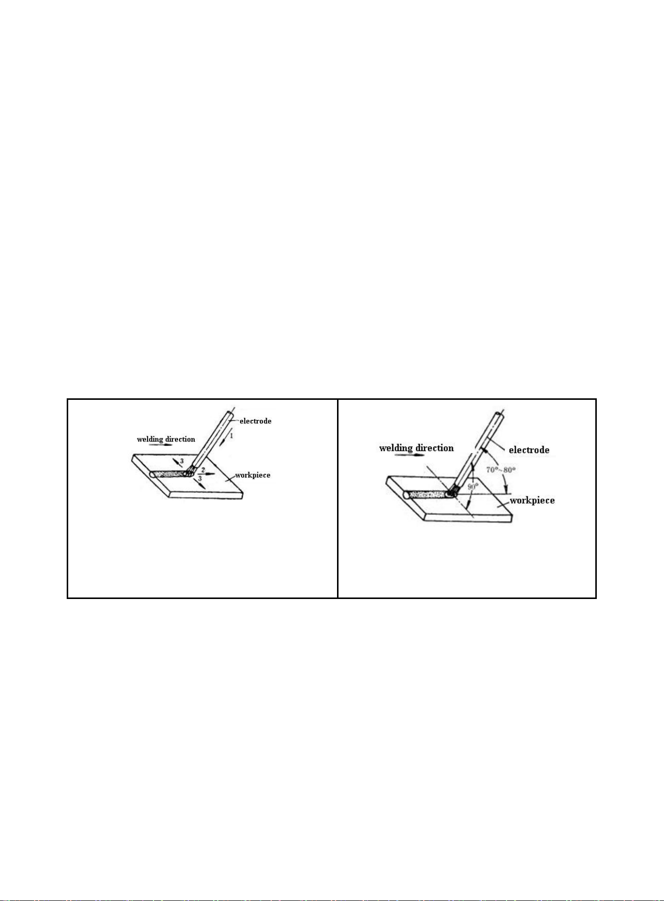
The electrode manipulation actually is a resultant movement in which the electrode simultaneously
moves in three basic directions: the electrode gradually moves along the welding direction; the electrode
gradually moves toward the weld crater; and the electrode transversely swings. (See Figure 29)
Electrode should be correctly manipulated in three movement directions after arc is ignited. In butt
welding and flat welding, the most important is to control the following three aspects: welding angle, arc
length and welding speed.
Welding angle: the electrode should be inclined in 70~80º forwards. (See Figure 30)
Arc length: the proper arc length is equal to the diameter of electrode in general.
Welding speed: proper welding speed should make the crater width of the weld bead about twice the
diameter of the electrode, and the surface of the weld bead should be flat with fine ripples. If the
welding speed is too high, and the weld bead is narrow and high, the ripples are rough, and the
fusion is not well implemented. If the welding speed is too low, the crater width is excessive, and the
workpiece is easy to be burned through. Besides, current should be proper, electrode should be
aligned, arc should be low, and welding speed should not be too high and should be kept uniform
during the whole welding process.
1-downwards feed
2-move toward welding direction
3-transversely swing
Figure 29 basic movement directions of
electrode
Figure 30 Angles of electrode in flat welding
Arc extinguishing
Arc extinguishing is unavoidable during welding. Poor arc extinguishing may bring shallow weld crater
and poor density and strength of weld metal by which cracks, air holes, slag inclusion and shortage the
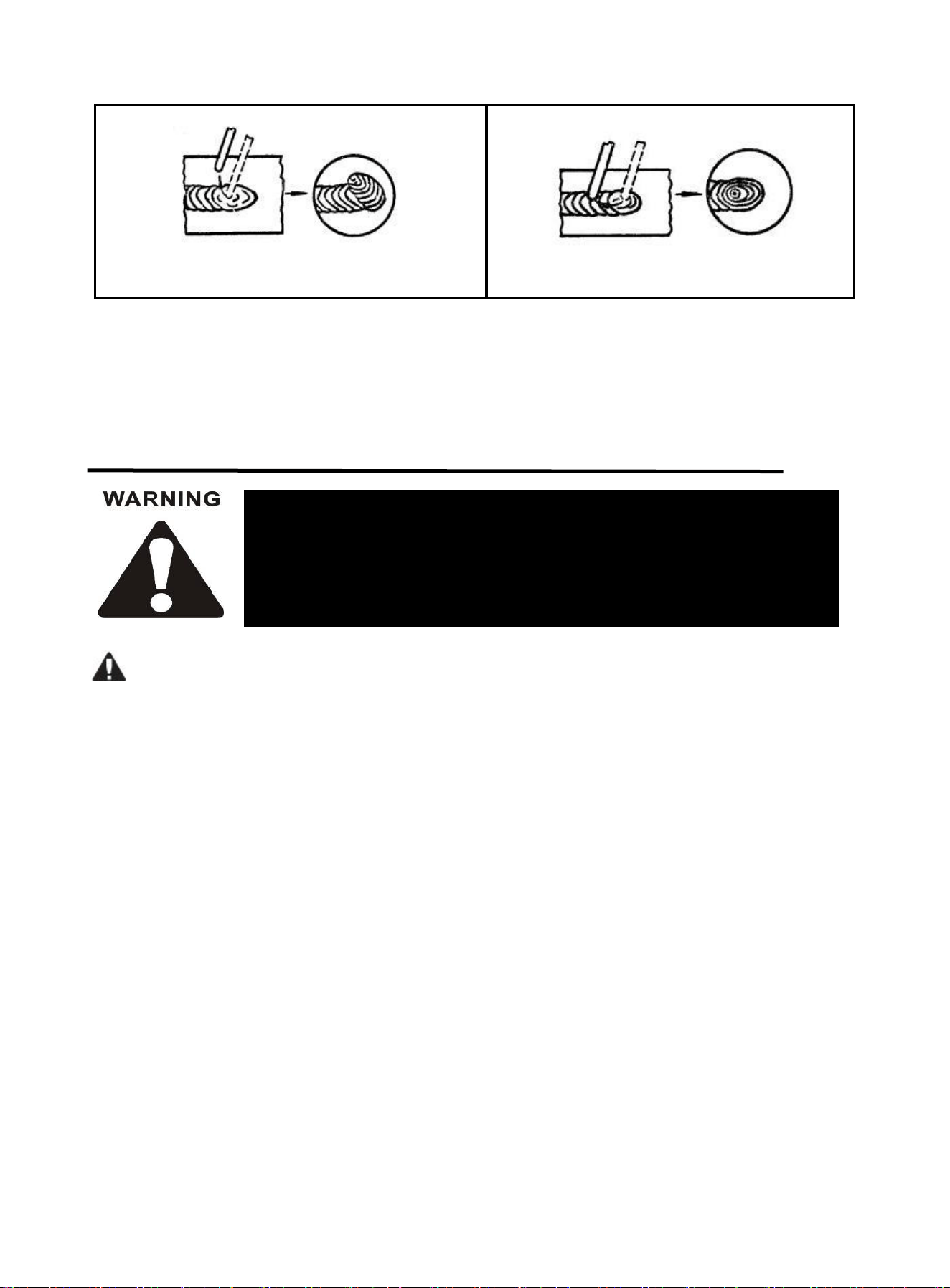
like are easy to be produced. Gradually pull the end of the electrode to the groove and raise the arc
when extinguishing arc, in order to narrow the weld crater and reduce the metal and heat. Thus, defects
such as cracks and air holes can be avoided. Pile up the weld metal of the crater to make the weld crater
sufficiently transferred when extinguishing arc. Then, remove the excessive part after welding. The
operation modes of arc extinguishing are shown in the figure below.
https://www.arccaptain.com/
33
All welder maintenance should be carried out by qualified professional
operators; any wrong connection or installation will damage to PCB or
components. To avoid electric shock, burning or other personal injuries,
please do maintenance 5 minutes after welder is powered off.
a) arc extinguishing at the outside of weld bead b) arc extinguishing on the weld bead
Figure 31 Arc extinguishing modes
Weldment cleaning
Clean welding slag and spatter with wire brush, etc after welding.
9. TROUBLESHOOTING
Please do the following inspection before maintenance:
1) Please check if welder input voltage is within 220V/110V±15%.
2) Please make sure the correct and tight connection of input cable.
3) Please make sure the correct and tight connection of welding cable.
4) Please make sure gas circulation is normal; please use pure argon gas and adjust gas flow per actual
welding demands.
5) Please make sure all PCB terminals are correctly and tightly connected.
https://www.arccaptain.com/
34
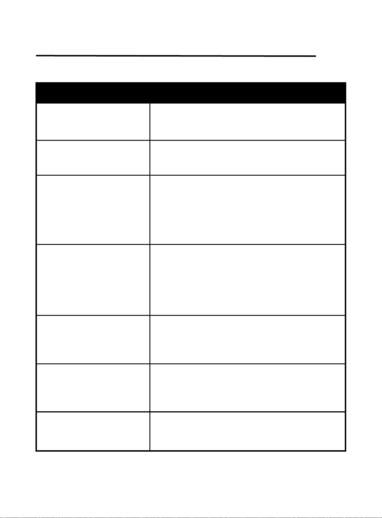
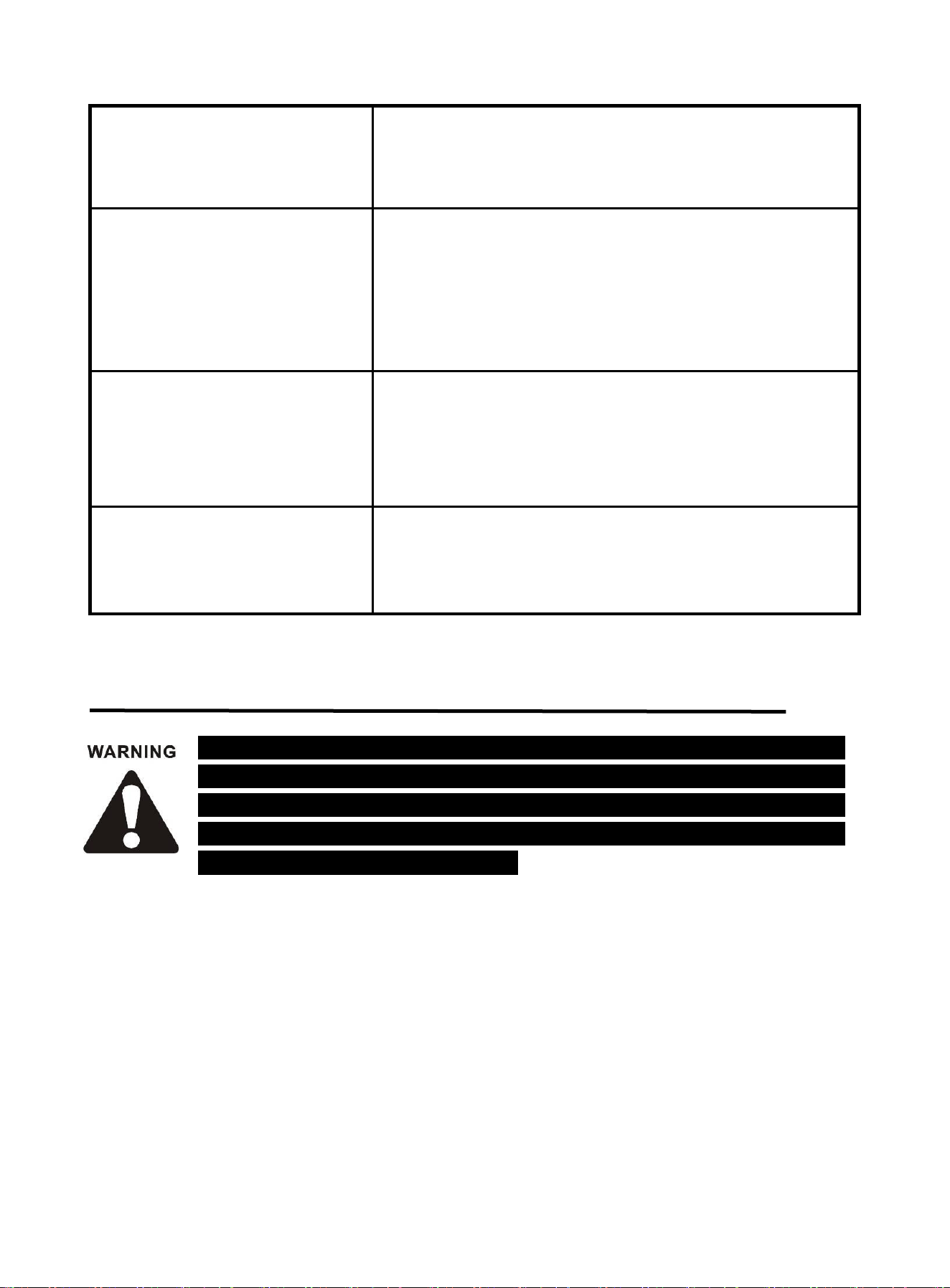
9.1 Error code and welding processing problems
Welder failure and welding process problems
Malfunction phenomena
Solutions
Power supply indicator doesn’t light
Fan doesn’t work and there is no
current output
Please make sure power switch is on.
Please make sure there is electricity input.
Power supply indicator lights Fan
doesn’t work and there is no
current output
Under-powered DC24V supply or main replay is not closed.
Check if DC15V power supply is normal or not.
Fan works; abnormity light doesn’t
light, but with no welding output;
Make sure operator has pulled the torch trigger and make sure
it’s in good contact.
Check whether DC15V power supply is normal;
Check whether drive wire is tightly connected.
Check whether panel potentiometer is open-circuited.
Output terminal connection is in poor connection.
Black welding spot
Please make sure argon outlet from welding torch nozzle is
normal.
Argon flow is too small; generally argon flow should be 5L/min;
Please check whether air circulation is in good sealing condition
and please check gas purity;
Please make sure there is no strong airflow in the welding site.
Poor protection for welding bead in
the end of welding processing.
Don’t move the welding torch immediately after welding is
finished, so that to retain the shielding gas’s protection for
high temperature welding bead.
Prolong post-flow time.
Hard to achieve successful arc
ignition; frequent current interruption.
Change a new tungsten;
Remove tungsten oxidation layer.
Prolong post-flow time;
Adjust tungsten electrode discharge distance(around0.8mm)
Unstable welding current
Please make sure power network is normal.
Connect different power input cables if there are other
equipments of strong interferences.
https://www.arccaptain.com/
35
The following operation requires sufficient professional knowledge on electric
aspect and comprehensive safety knowledge. Operators should be holders of
valid qualification certificates which can prove their skills and knowledge. Make
sure the input cable of the machine is disconnected from the electricity utility
before uncovering the welding machine.
No HF discharge when pull the torch
trigger
Please check whether OCV is normal(DC65V);
Please make sure torch trigger control loop is normal;
Please check whether HF control loop is normal;
Display indicates E10
Over-current protection
Restart machine.
Check if flat cable between front PCB and top PCB is well
connected.
If it is not fixed, the circuit fails. Please contact your distributor.
Display indicates E61
Over-heat protection
Wait for 5-7 minutes and machine will go back to normal
operation automatically;
The thermistor is damaged. Please replace it.
Display indicates E34
Under-voltage protection for 15V
Turn off the machine and restart it. If this the alarm cannot be
eliminated, please contact professional maintenance personnel.
10. MAINTENANCE
Check periodically whether inner circuit connection is in good condition, connector is fastened (esp.
plugs or components). Tighten the loose connection. If there is oxidization, remove it with
sandpaper and then reconnect.
Keep hands, hair and tools away from the charged parts such as the fan to avoid personal injury or
machine damage when the machine is energized.
Clean the dust periodically with dry and clean compressed air. If welding environment with heavy
smoke and pollution, the machine should be cleaned daily. The pressure of compressed air should
be at a proper level in order to avoid the small parts inside the machine being damaged.
https://www.arccaptain.com/

36
Avoid water and vapor infiltrating the machine. If there is, dry it and use tramegger to check the
insulation of the equipment (including that between the connections and that between the
connection and the enclosure). Only when there are no abnormal phenomena anymore, can the
machine be used.
Check periodically whether the insulation cover of all cables is in good condition. If there is any
dilapidation, rewrap it or replace it.
Put the machine into the original packing in dry location if it is not to be used for a long time.
https://www.arccaptain.com/