EAD50 EAD20 User Guide
1
EN
Electronic Acoustic Drum Module
User Guide
V1.10
V1.00
EAD50
Main changes from V1.00 to V1.10
Applicable
Page(s)
• Now added the Preset Scene “P071 Dry,” which lets you output the microphone dry sound.
96
• Now expanded the setting range for the input gain to the microphone.
[MIC/TRIG]
g
[F3] Setting
g
Mic
g
Mic In
g
Gain
109
• Now improved the operation of automatic gain adjustment for the microphone.
[MIC/TRIG]
g
[F3] Setting
g
Mic
g
Mic In
g
Gain Auto Setup
110
• Now improved the operation of the Noise Gate which lets you set also the Threshold and
Release.
[MIC/TRIG]
g
[F3] Setting
g
Mic
g
Mic In
g
Noise Gate
111
• Now improved the operation of the Voice Layer settings which can be made more visually
and easily.
[MIC/TRIG]
g
[F3] Setting
g
Kit
g
Voice
g
Voice
g
Layer Mix
136
• Now you can audition the sound of the currently selected User Voice on the following screen.
[MIC/TRIG]
g
[F3] Setting
g
Kit
g
User Voice
g
Sort Wave
144
• Now improved the behavior and screen display for the Looper and the Sampling.
174, 180
• Fixed other minor problems.
--
©2026 Yamaha Corporation
Published 09/2026
IP-A0
From time to time, Yamaha may update product firmware without prior notice.
The latest firmware and corresponding manuals can be downloaded from the following
website:
https://download.yamaha.com/
You can check the firmware version of this unit by going to [Menu]
"
Version (Page 208).
EAD50 EAD20 User Guide
2
Contents
Introduction ....................................................................................................................4
About the Manuals ................................................................................................................... 4
Included Accessories
.............................................................................................................. 4
How to Search for Parameters (from Page 76)
......................................................................... 4
Model Indication in the User Guide
......................................................................................... 4
Panel Controls and Functions ......................................................................................5
EAD50
Top Panel ................................................................................................................. 5
EAD50
Rear Panel ............................................................................................................... 8
EAD20
Top Panel ............................................................................................................... 10
EAD20
Rear Panel ............................................................................................................. 12
Sensor Unit
............................................................................................................................. 13
Precautions for Using USB terminals
..................................................................................... 14
Precautions for Using SD Cards (
EAD50
only) ................................................................. 15
Glossary ....................................................................................................................... 16
What is “EAD”?
............................................................................................................18
Acoustic Drum Section (with Microphone Inputs) .................................................................. 19
Electronic Drum Section (with Trigger Inputs)
........................................................................ 21
How to Configure Trigger Inputs ................................................................................23
Generating Trigger Sounds (Kits, Insts, and Voices) ............................................................. 23
How to Configure Trigger Signal Inputs
................................................................................. 24
Trigger Input Mode
................................................................................................................. 27
Configuring Effects ......................................................................................................28
Diagram of Effects .................................................................................................................. 28
Configuring Effects
................................................................................................................. 29
Equalizer Shape
..................................................................................................................... 32
Internal Memory Structure ..........................................................................................33
Details of User Voice .............................................................................................................. 34
Composition of Scenes
.......................................................................................................... 35
Composition of Live Sets (
EAD50
only) ............................................................................ 36
Preparation ................................................................................................................... 37
Basic Setups .......................................................................................................................... 37
Connections to External Devices—Inputs
............................................................................. 41
Connections to External Devices—Outputs
........................................................................... 45
Connections to External Devices— I/O
.................................................................................. 49
Setting examples for Specific Use Cases
.............................................................................. 52
Turning the Power On and Off
................................................................................................ 58
Checking the Version
............................................................................................................. 58
Auto Power Off (Automatically Turns Off the Power)
.............................................................. 58
Restoring Default Factory Settings (Factory Reset)
............................................................... 59
EAD50 EAD20 User Guide
3
Basic Operations .........................................................................................................60
Basic Screen Operations ...................................................................................................... 60
Selecting and Basic Settings for Input Sources—Mic Sounds (
EAD50
only) ................... 62
Selecting Input Sources and Basic Settings—Trigger Signals
.............................................. 63
Naming Data
.......................................................................................................................... 66
Changing the Data Order
....................................................................................................... 67
Function Tree Diagram ................................................................................................68
Settings in Screens (Parameters)
............................................................................... 76
Modifier Knob Operations ................................................................................................... 76
Operating LED Rotary Faders (
EAD50
only) .................................................................. 87
[SCENE]
................................................................................................................................ 90
[STORE]
............................................................................................................................ 95
EAD50
List of Preset Scenes ......................................................................................... 96
EAD20
List of Preset Scenes ....................................................................................... 102
[MIC/TRIG]
.......................................................................................................................... 106
[F3] Setting
"
Mic/Kit Vol
................................................................................................. 108
[F3] Setting
"
Mic
........................................................................................................... 108
[F3] Setting
"
Trigger
...................................................................................................... 118
[F3] Setting
"
Kit
............................................................................................................. 126
[F3] Setting
"
Effect
........................................................................................................ 147
[CLICK]
............................................................................................................................... 157
Setting the Tempo, Playing, and Stopping Clicks
.......................................................... 157
Click Settings
.................................................................................................................. 159
[RECORDER]
..................................................................................................................... 164
[RECORDER]-Recorder
.................................................................................................. 164
[RECORDER]-Looper
.................................................................................................... 174
[RECORDER]-Sampling
................................................................................................ 180
[LIVE SET]
(
EAD50
only) ......................................................................... 185
[MENU]
..................................................................................................... 187
Utility
............................................................................................................................... 188
Output
............................................................................................................................. 190
Aux In
.............................................................................................................................. 192
USB Audio
...................................................................................................................... 196
Bluetooth (
EAD50
only) .............................................................................................. 200
File
.................................................................................................................................. 205
Factory Reset.................................................................................................................. 208
Version
............................................................................................................................ 208
Appendix ....................................................................................................................209
Troubleshooting .................................................................................................................... 209
Message List
........................................................................................................................ 219
Content List
.......................................................................................................................... 221
EAD50
Block Diagram ..................................................................................................... 222
EAD20
Block Diagram ..................................................................................................... 226
Specifications
....................................................................................................................... 230
EAD50 EAD20 User Guide
4
The electronic acoustic drum module is a product used to acquire sounds from acoustic drums or percussion
performances via the included Sensor Unit, modify them with Effects and sound quality processing, and then output
the modified sounds to speakers or headphones. In addition to the microphone sound, the Sensor Unit can detect
the Trigger Signals which produce electronic drum sounds (Voices). That means it can blend the natural resonance
of acoustic drums with the powerful sounds of electronic drums to create performances with a wide range of
expression.
About the Manuals
This product is shipped with the following instruction manuals.
z
Quick Guide (paper sheet included with product)
Mainly intended to help users get started using the product quickly, this guide includes only a limited amount of key
information. Be sure to read the “Precautions,” “Notice,” and “Information” sections before using the product.
z
User Guide (this file, only released via the website)
This guide explains all the other information about the product that is not included in the Quick Guide.
z
Data List (only available via the website)
The Data List lists all contents included in the product and MIDI-related specifications.
All three manuals indicated above, including the Quick Guide, are available from the Yamaha Download website. Open the
website indicated below, select your country or region, select “Manual Library,” enter the model name (such as “EAD”), and
then click “Search.”
Yamaha Download Site: https://download.yamaha.com/
Included Accessories
For a list of accessories, refer to the Quick Guide (paper sheet included with product).
How to Search for Parameters (from Page 76)
If viewing this document on a computer, the link function can be used to jump to the desired section by
clicking on the section or the terminology search function can be used. Also use the function for jumping
to the beginning of any chapter by clicking on the corresponding tab shown on the right side of each
page.
Model Indication in the User Guide
This document includes information for two models, the EAD50 and EAD20.
Information that differs depending on the model is indicated with the corresponding color-coded label below.
EAD50
Only applies to the EAD50 model
EAD20
Only applies to the EAD20 model
Introduction
EAD50 EAD20 User Guide
5
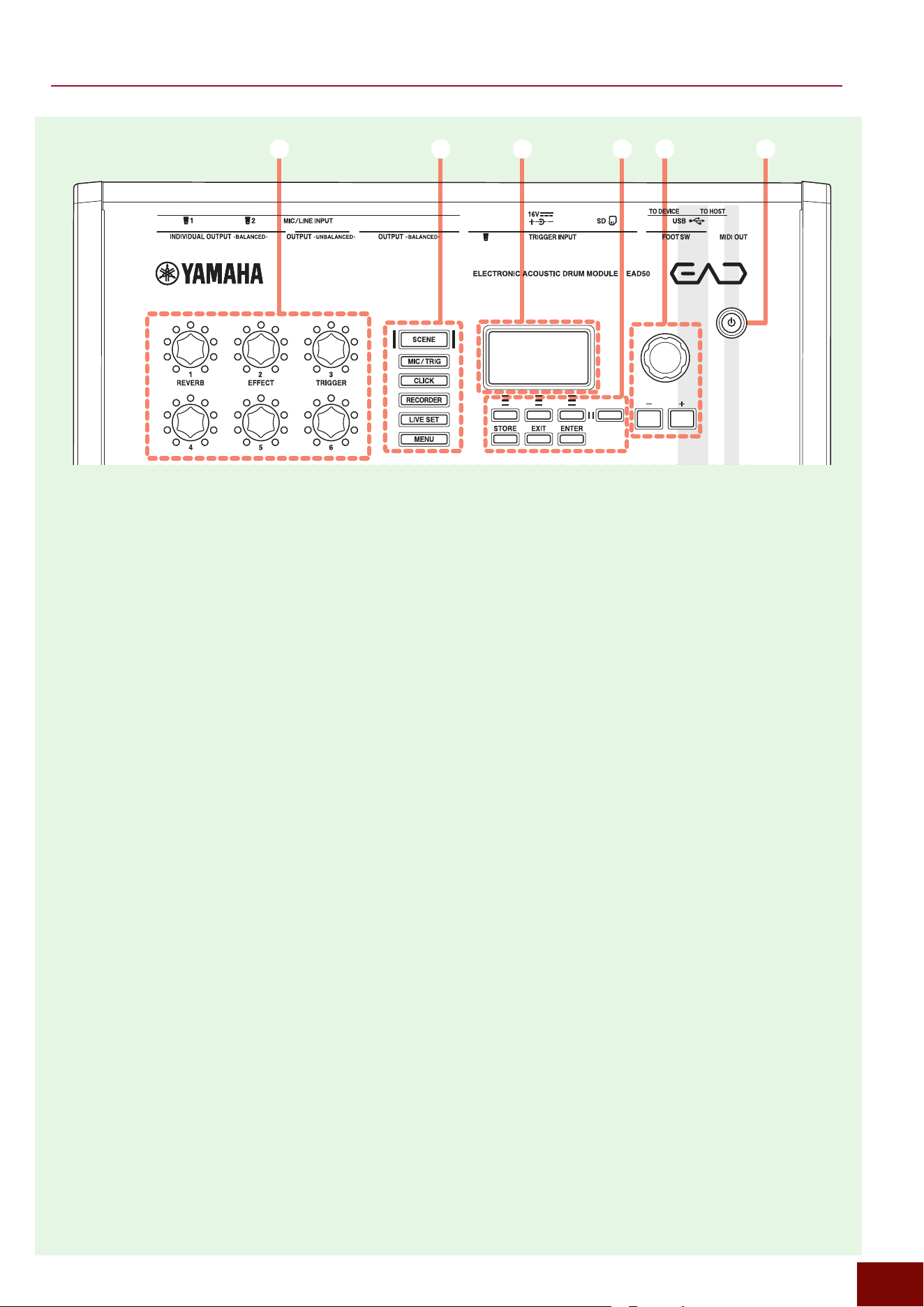
EAD50
Top Panel
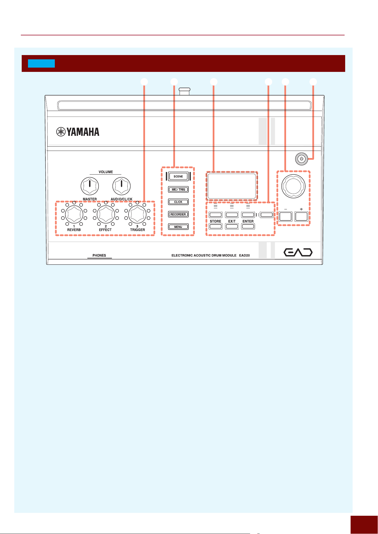
12 3 56
h 9
4
jk
7
Panel Controls and Functions
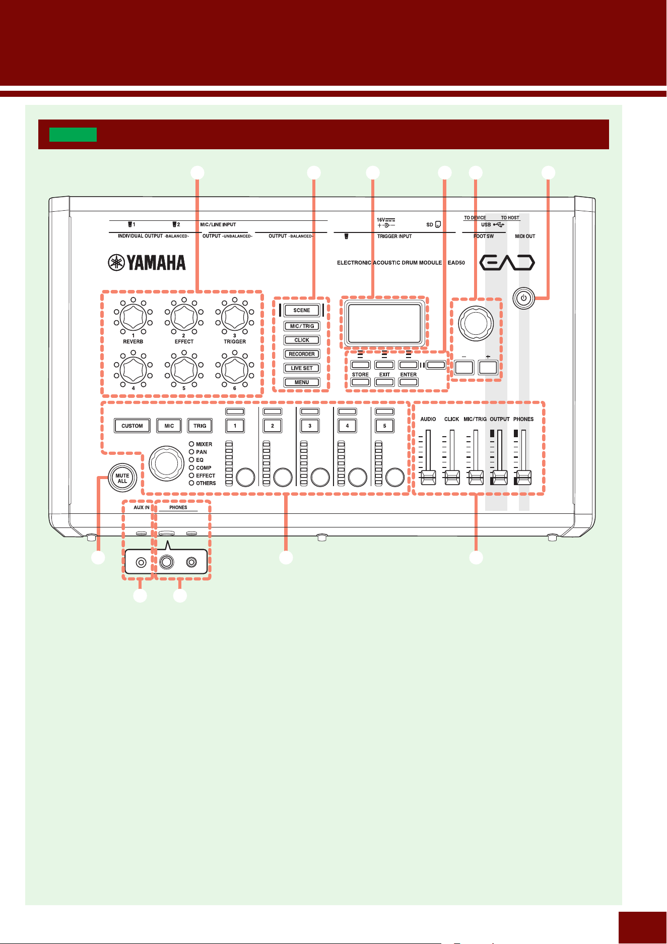
1
Standby/On Button
2
Display Screen
3
Screen Operation Buttons
4
Mode Buttons
5
Knob and [+]/[−] Buttons
(for specifying setting values)
6
Modifier Knobs
7
[MUTE ALL] Button
8
LED Rotary Faders and Related Buttons/Knobs
9
Volume Sliders
j
[PHONES] Jacks
k
[AUX IN] Jack
EAD50 EAD20 User Guide
6
Panel Controls and Functions
12 3 56
h 9
4
jk
7
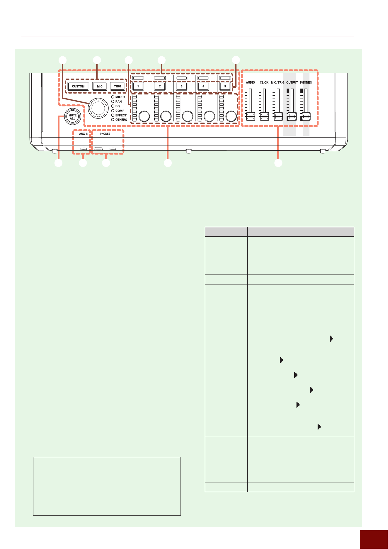
4
Mode Buttons
These buttons cover various functions of this product,
which lets you enter the desired mode by pressing any of
them. The currently selected mode button is lit.
• SCENE
_
Page 90
• MIC/TRIG
_
Page 106
• CLICK
_
Page 157
• RECORDER
_
Page 164
• LIVE SET
_
Page 185
• MENU
_
Page 187
5
Knob and [+]/[−] Buttons
(for specifying setting values)
Both the knob and buttons operate the same functions.
They are mostly used to set numeric values for the various
parameters on the screen.
6
Modifier Knobs .......................... Page 76
These knobs can be operated to change various tone
characteristics or switch between functions during
performances. Though many parameters are located
deep within the screen hierarchy, frequently used ones
can be assigned to these knobs.
1
Standby/On Button
Turns this product on or off.
2
Display Screen ........................... Page 60
This display is used to indicate the current status of this
product, the status of each parameter setting, and other
information. The screen contrast level can be adjusted by
tapping [MENU]
"
Utility
"
LCD Contrast (Page 188).
3
Screen Operation Buttons
The first row of buttons is for switching between functions
linked to the display screen. Though the names of these
buttons are not specifically printed on the panel, for
explanatory purposes they are referred to as F1, F2, F3,
and Alt. For more information, refer to Page 60.
The second row includes the following buttons.
• [STORE] Button
Used to save Scenes (Page 90) and Live Sets
(Page 185). For more information, refer to Page
95.
• [EXIT] button
Used to exit the current screen or display a screen
that is 1 level higher in the screen hierarchy. The top
screen of a Scene (Scene Selection screen) also
includes a function (All Sound Off) for muting all
Triggers currently being expressed.
• [ENTER] button
Used to display the screen that is 1 level lower in the
screen hierarchy or to execute functions.
EAD50 EAD20 User Guide
7
Panel Controls and Functions
h 9
jk
7
h
–
4 h
–
2h
–
1h
–
5
h
–
3
7
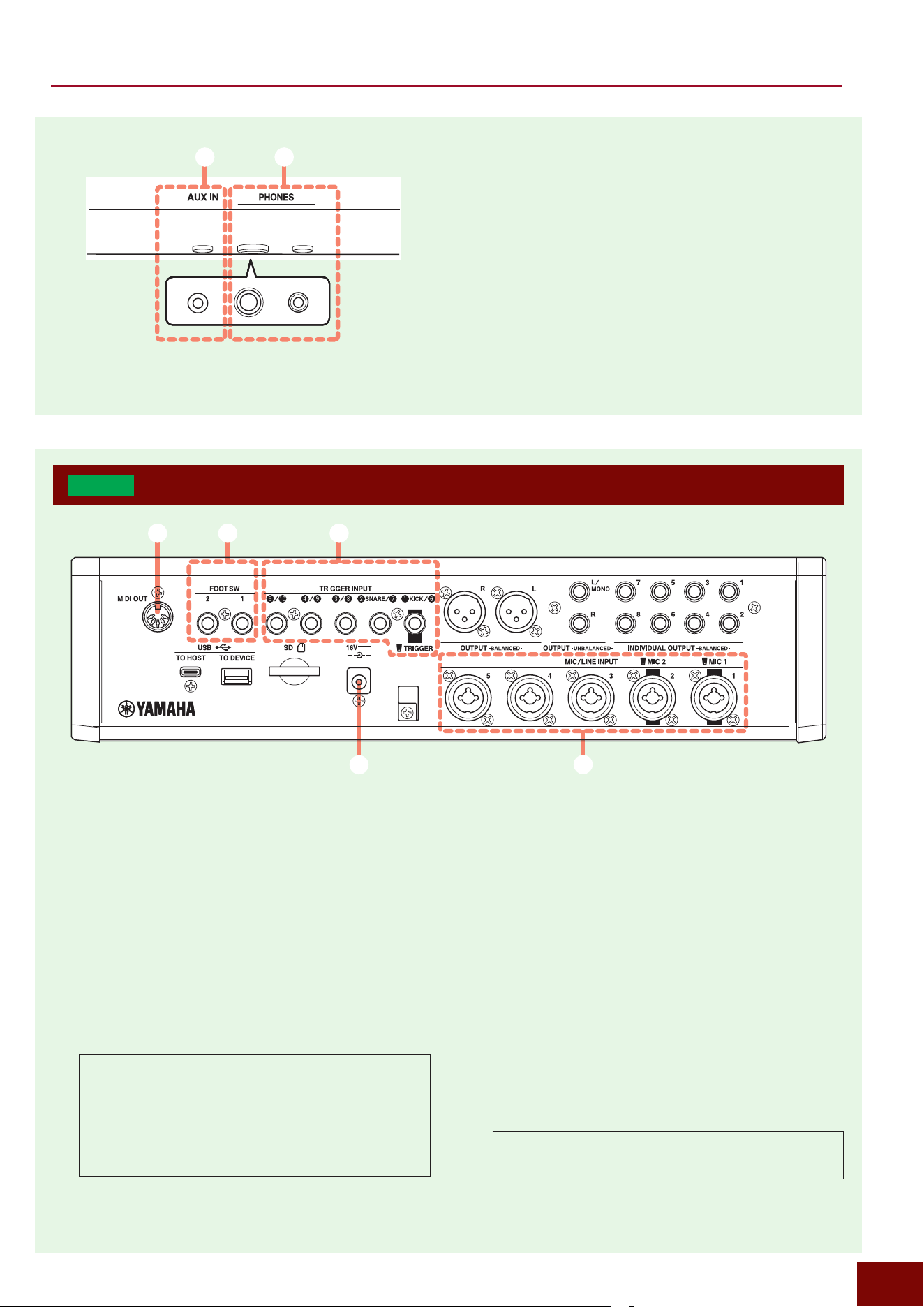
[MUTE ALL] Button
This mutes all channels which are played by this product.
The button is lit when sound is muted. If sound is muted,
the supply of phantom power (Pages 8 and 109) to
the [MIC/LINE INPUT] jacks is also temporarily stopped.
8
LED Rotary Faders and Related
Buttons/Knobs
.................................................... Page 87
8
-
1 LED Rotary Faders
Rotating these faders applies various effects to the
corresponding channel.
8
-
2 Channel Lamps
These lamps indicate the pairing status of respective
channels. When the [MIC] button is lit, it also functions
as a peak indicator. When playing the drums, the optimal
status is when the peak indicator flashes occasionally
when the overall drum set is hit.
8
-
3 Channel On/Off Buttons
These buttons toggle each channel on (lit) or off (unlit).
8
-
4 Fader Mode Buttons
These buttons are used to select the channels controlled
by the LED rotary faders.
• If [MIC] is lit: The faders control mic inputs (Mic1 – Mic5).
• If [TRIG] is lit: The faders control Trigger sounds (Kick,
Snare, and Trig3–10).
• If [CUSTOM] is lit: The faders control the other channels.
8
-
5 Fader Function Select Knob
Turn this knob to select the fader function. The selected
function can be confirmed based on which of the LED
lamps to the right (MIXER to OTHERS) is lit.
Channel
These are the individual sounds that make up the overall
sound produced by this product. Channels include
the input sounds input via the respective [MIC/LINE
INPUT] jacks (shown as Mic1–5 on the screen) and
the respective Trigger sounds input via the [TRIGGER
INPUT] jacks (shown as Kick, Snare, or Trig3–22).
9
Volume Sliders
Operating these five sliders adjusts the volume level of
individual audio sounds produced by this product as
described below.
Slider Audio Volume Adjusted
[AUDIO]
• Sounds input to the [AUX IN] jack
• Sounds input to the [USB TO HOST]
terminal
• Sounds input via Bluetooth
• Recorder function playback sounds
[CLICK] CLICK playback sounds
[MIC/TRIG]
• Mic sounds: Sounds input via the
[MIC/LINE INPUT] jacks
• Trigger sounds: Sounds input via the
[TRIGGER INPUT] jack
• Audio file preview sounds input from
external memory
[MIC/TRIG]
"
[F3] Setting
"
Kit
"
Inst
"
Inst
"
Import Wave
"
[F3]
[MIC/TRIG]
"
[F3] Setting
"
Kit
"
User
Voice
"
Import Wave
"
File to Bank
"
[F1]
[CLICK]
"
[F3] Setting
"
Click
"
Import
Wave
"
[F3]
[RECORDER]
"
(Sampling)
"
[F4] Load
"
[F1]
[MENU]
"
File
"
File Wave
"
Rename,
Delete
"
[F3]
• User Voice preview
[RECORDER]
"
(Sampling)
"
[F7] LoadWM
"
[F1]
[OUTPUT] • Sounds output via the [OUTPUT]
jack (indicated on the screen as
“Main Out”)
• USB Audio Out 1/2
• Recording volume for Recorder,
Looper, and Sampling
[PHONES] Volume for headphones
EAD50 EAD20 User Guide
8
Panel Controls and Functions
j
[PHONES] Jacks
Used to connect headphones to output the sound played
on this product including the audio input from the external
device. This product is equipped both with the stereo
mini-plug jack and standard stereo jack.
NOTE
Using both jacks simultaneously will decrease the output
volume to the headphones.
k
[AUX IN] Jack
Jack compatible with stereo mini plugs. Connect an
electronic keyboard, portable music player, or other
device to input audio to this product.
jk
3
[TRIGGER INPUT] Jacks ........... Page 24
These jacks are compatible with standard stereo phone
plugs and are used to connect cables from electronic
drum pads or from Trigger sensors attached to acoustic
drums. The [
q
KICK/
y
] jack is intended for connecting
the cable from the included DSU50 sensor unit.
4
[FOOT SW] Jacks ....................... Page 42
Used to connect a separately sold pedal or foot switch/
controller.
5
[MIDI OUT] Terminal .................. Page 47
Used for connecting a MIDI cable. This product conducts
MIDI communications via the [USB TO HOST] terminal,
but only MIDI output can be sent via a MIDI cable. Use
the jack to output sounds from a drum tone generator that
does not have a USB terminal.
MIDI is a registered trademark of the Association of
Musical Electronics Industry (AMEI).
EAD50
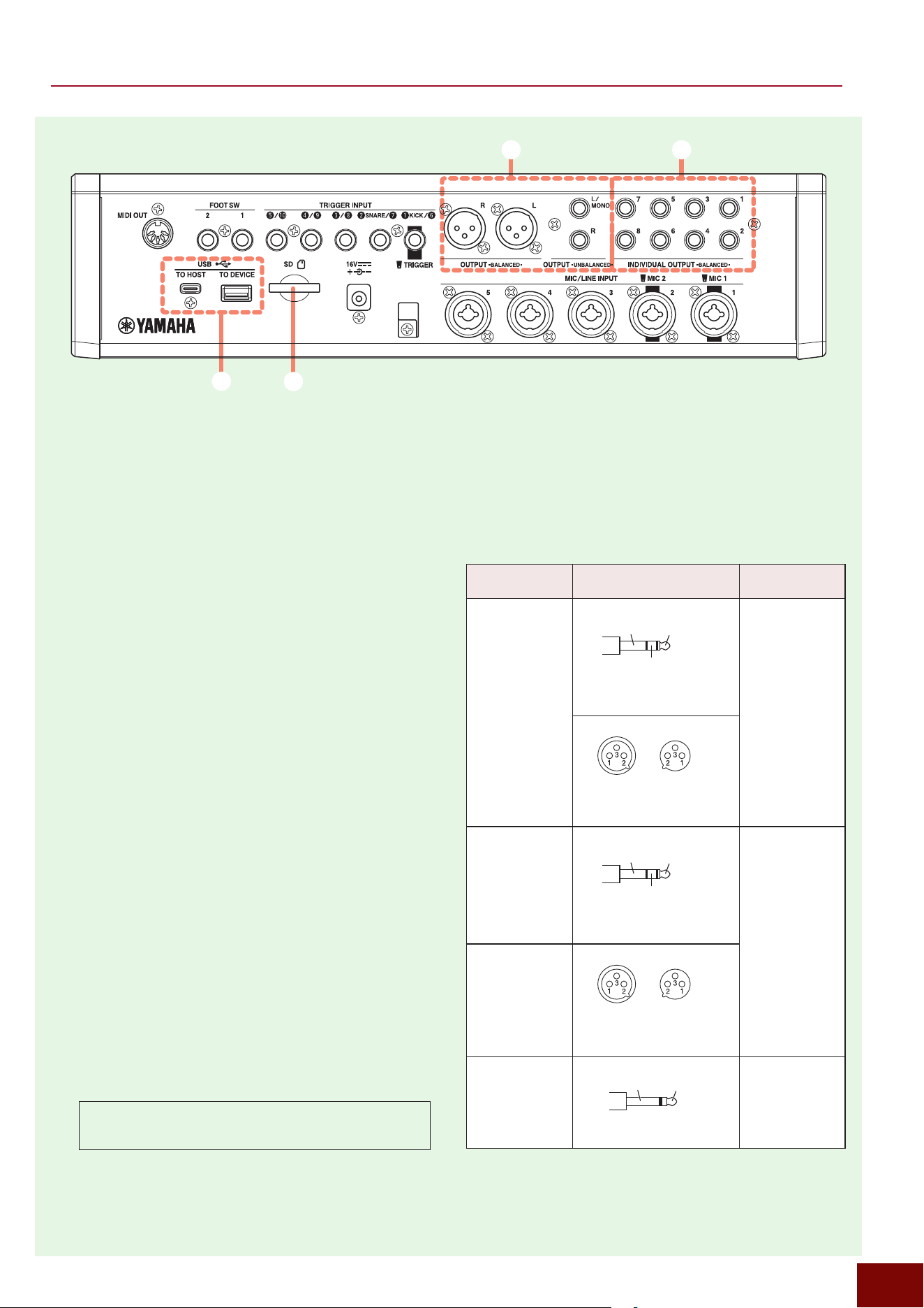
Rear Panel
1
2
5 4 3
1
DC IN Jack
Used to connect the provided AC adapter.
2
[MIC/LINE INPUT] Jacks ............ Page 41
These are jacks compatible with both TRS phone plugs
and XLR connectors. Both are balanced connections.
The XLR connectors are used for audio connections for
microphones (devices that require gain amplification),
such as for miking acoustic drum performances. The
TRS phone jacks are used to connect electronic musical
instruments (or other devices with a high output level).
Jacks 1 and 2 are intended for cable connections from the
included DSU50 sensor unit.
Phantom Power
This product can supply power to XLR-type condenser
mics or other devices that need power via these
jacks. That is referred to as “phantom power”, which
is supplied only to the XLR connectors. For more
information, refer to Page 109.
EAD50 EAD20 User Guide
9
Panel Controls and Functions
6
[OUTPUT] Jacks
These jacks are used to output all sounds produced by
this product. They correspond to the channels indicated
as [Main Out] in parameters shown on the screen.
They include both XLR-type (balanced) and TS phone
(unbalanced) jacks. Both types output the same sound
signal. Select the appropriate jack based on the device
being connected.
NOTE
• To achieve monaural output, only connect the [L/MONO]
jack.
• If a balanced output must unavoidably be connected to an
unbalanced device, match the ground potentials of both
devices. Unmatched potentials could cause a product
damage or failure. For cables connecting unbalanced
devices, connect pin 3 to cold and pin 1 to ground.
7
[INDIVIDUAL OUTPUT] Jacks ... Page 45
These output jacks are used to individually output audio
sounds from respective channels. Outputting channels
individually allows sending the sound necessary for
specific people or applying Effects individually to specific
channels, for example.
8
USB Terminals ........................... Page 14
This product includes two types of USB terminals (Type-A
and Type-C).
The Type-C [USB TO HOST] terminal is used to connect
a computer or other host device for MIDI or audio
communication. The Type-A [USB TO DEVICE] terminal
is for connecting a USB flash drive, electronic musical
instrument, or other such device, with this product
functioning as the host device. A variety of data created
on this product can be saved in a USB flash drive. If an
electronic instrument is connected, USB Trigger Link
function of this product and connected devices can be
used to input MIDI signals from that instrument.
USB Type-C™ and USB-C™ are trademarks of the USB
Implementers Forum.
9
8
6 7
9
SD Memory Card Slot ................ Page 15
In addition to a USB flash drive, an SD card can be used
as storage media for saving data created on this product.
Polarity of Jacks
2
,
6
, and
7
Connector Connector Polarity
Balanced/
Unbalanced
MIC/LINE INPUT
TRS phone plugs*
T (tip): Hot (+)
R (ring): Cold (–)
S (sleeve): Ground
Balanced
XLR connectors
Pin-1: Ground
Pin-2: Hot
Pin-3: Cold
INDIVIDUAL
OUTPUT
-BALANCED-
TRS phone plugs*
T (tip): Hot (+)
R (ring): Cold (–)
S (sleeve): Ground
Balanced
OUTPUT
-BALANCED-
XLR connectors
Pin-1: Ground
Pin-2: Hot
Pin-3: Cold
OUTPUT
-UNBALANCED-
TS phone plugs
S T
T (tip): Signal
S (sleeve): Ground
Unbalanced
* Also can be connected using a TS phone plug instead of a TRS
phone plug. In that case, the connection is unbalanced.
S
T
R
S
T
R
EAD50 EAD20 User Guide
10
Panel Controls and Functions
1
Standby/On Button
Turns this product on or off.
2
Display Screen ........................... Page 60
This display is used to indicate the current status of this
product, the status of each parameter setting, and other
information. The screen contrast level can be adjusted by
tapping [MENU]
"
Utility
"
LCD Contrast (Page 188).
3
Screen Operation Buttons
The first row of buttons is for switching between functions
linked to the display screen. Though the names of these
buttons are not specifically printed on the panel, for
explanatory purposes they are referred to as F1, F2, F3,
and Alt. For more information, refer to Page 60.
The second row includes the following buttons.
• [STORE] Button
Used to save Scenes (Page 90). For more
information, refer to Page 95.
• [EXIT] button
Used to exit the current screen or display a screen
that is 1 level higher in the screen hierarchy. The top
screen of a Scene (Scene Selection screen) also
includes a function (All Sound Off) for muting all
Triggers currently being expressed.
• [ENTER] button
Used to display the screen that is 1 level lower in the
screen hierarchy or to execute functions.
EAD20
Top Panel
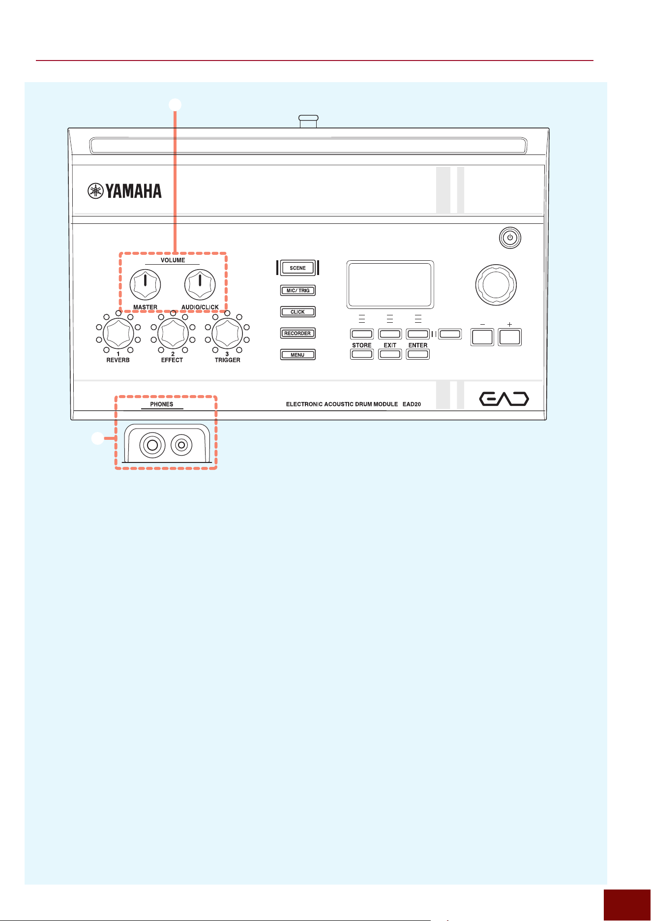
12 34 56
4
Mode Buttons
These buttons cover various functions of this product,
which lets you enter the desired mode by pressing any of
them. The currently selected mode button is lit.
• SCENE
_
Page 90
• MIC/TRIG
_
Page 106
• CLICK
_
Page 157
• RECORDER
_
Page 164
• MENU
_
Page 187
5
Knob and [+]/[−] Buttons
(for specifying setting values)
Both the knob and buttons operate the same functions.
They are mostly used to set numeric values for the various
parameters on the screen.
6
Modifier Knobs .......................... Page 76
These knobs can be operated to change various tone
characteristics or switch between functions during
performances. Though many parameters are located
deep within the screen hierarchy, frequently used ones
can be assigned to these knobs.
NOTE
Though there are only 3 Modifier knobs, by operating the
[+]/[−] buttons/knobs, they can be used to switch between
not only function assignment settings 1 to 3 but also 4 to 6.
For more information, refer to Page 77.
EAD50 EAD20 User Guide
11
Panel Controls and Functions
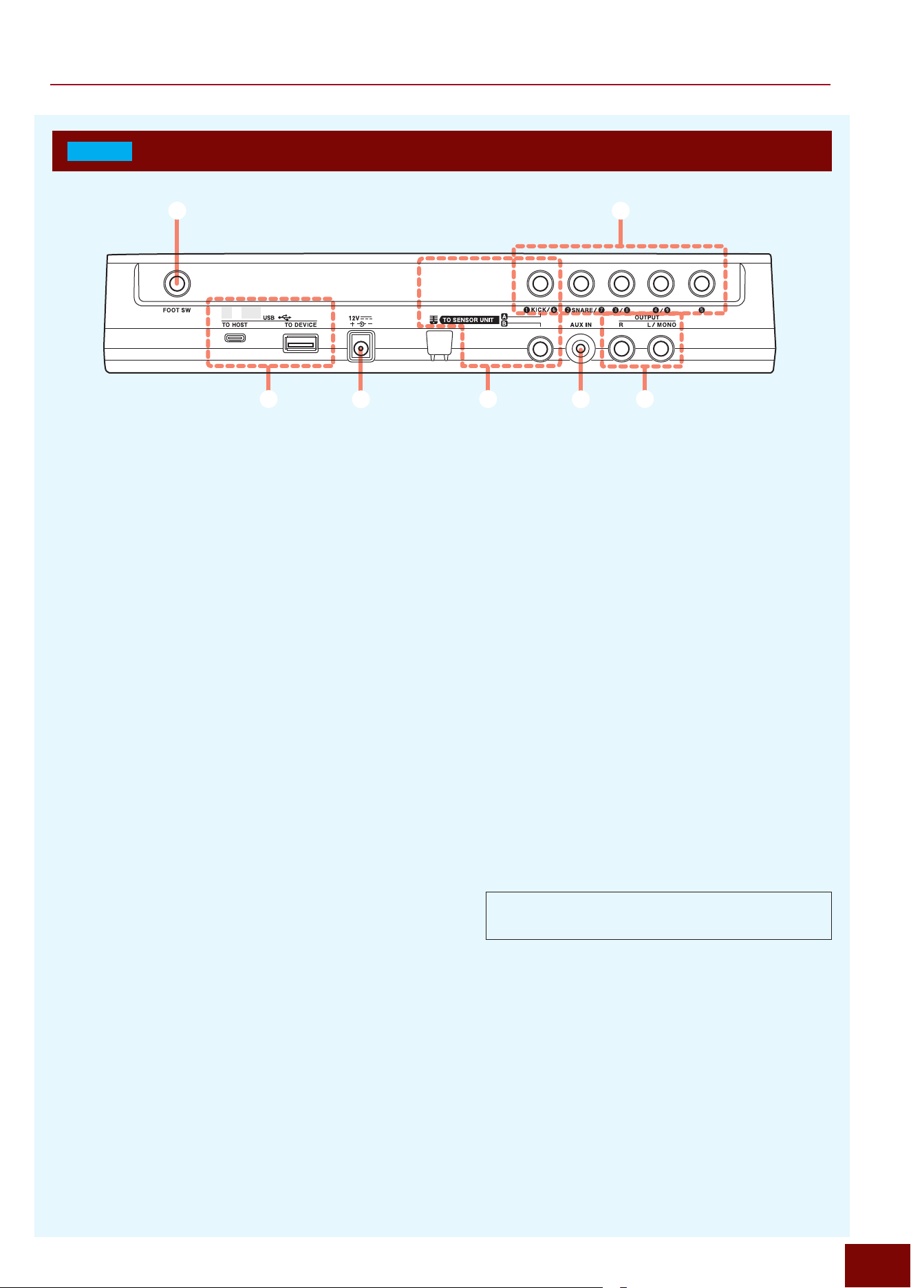
7
Volume Knobs
By operating these two knobs, the volume level of
individual audio sounds produced by this product can be
adjusted as described below.
[AUDIO/CLICK]
• Sound input to the [AUX IN] jack*
1
• Sound input to the [USB TO HOST] terminal*
1
• Recorder function playback sound*
1
• Click playback sound*
2
NOTE
The following screens can be used to set what the [AUDIO/
CLICK] knob controls.
*
1
: [MENU]
"
Utility (Page 4/4)
_
Audio Volume
*
2
: [MENU]
"
Utility (Page 4/4)
_
Click Volume
For more information, refer to Page 189.
7
8
[MASTER]
• Sounds output via the [OUTPUT] jacks (indicated on
the screen as “Main Out”)*
3
• Sounds output via the [USB TO HOST] terminal (USB
Audio Out 1/2)
• Recording volume for Recorder, Looper, and Sampling
• Volume for headphones*
4
NOTE
The following screens can be used to set what the
[MASTER] knob controls.
*
3
: [MENU]
_
Utility (Page 4/4)
_
Main Volume
*
4
: [MENU]
_
Utility (Page 4/4)
_
Phones Volume
For more information, refer to Page 189.
8
[PHONES] Jacks
These are connected to headphones, an internet
streaming device, or other source in order to output audio
from performances using the product or audio input to the
product. This product is equipped both with the stereo
mini-plug jack and standard stereo jack.
NOTE
Using both jacks simultaneously will decrease the output
volume to the headphones.
EAD50 EAD20 User Guide
12
Panel Controls and Functions
EAD20
Rear Panel
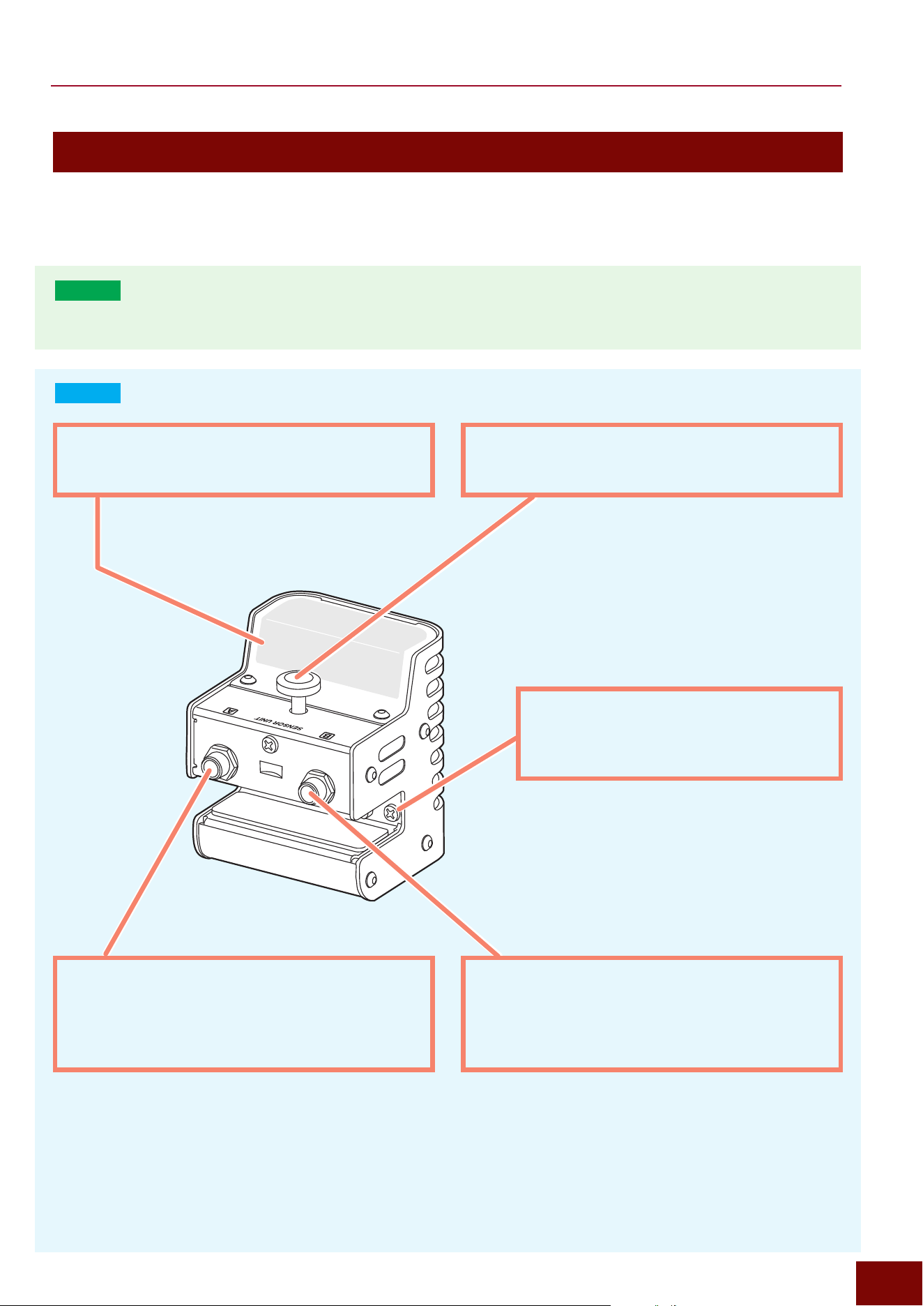
1 5
2 67
4 3
1
DC IN Jack
Used to connect the provided AC adapter.
2
[TO SENSOR UNIT] Jacks
Connected to the included Sensor Unit. Trigger signals
are input to the product by connecting Jack A on the
Sensor Unit to Jack A on the product. Microphone sounds
are input to the product by connecting the Jack B on the
Sensor Unit to Jack B on the product.
NOTICE
Jack B on the product is exclusively for connecting the
included Sensor Unit. Do not connect a commercially
available microphone to Jack B because it could damage
the equipment.
3
Trigger Input Jacks ........Pages 22 and 25
These jacks are compatible with standard stereo phone
plugs and are used to connect cables from electronic
drum pads or from Trigger sensors attached to acoustic
drums. The [
q
KICK/
y
] jack is intended for connecting
the cable from the included Sensor Unit.
4
[FOOT SW] Jacks ....................... Page 42
Used to connect a separately sold pedal or foot switch/
controller.
5
[AUX IN] Jack
Jack compatible with stereo mini plugs. Connect an
electronic keyboard, portable music player, or other
device to input audio to this product.
6
[OUTPUT] Jacks
Compatible with TS phone plugs (unbalanced), they can
be used to output all sounds produced by the product.
“Main Out” is indicated in parameters settings shown on
the screen.
NOTE
• To achieve monaural output, only connect the [L/MONO]
jack.
7
USB Terminals ........................... Page 14
This product includes two types of USB terminals (Type-A
and Type-C).
The Type-C [USB TO HOST] terminal is used to connect
a computer or other host device for MIDI or audio
communication. The Type-A [USB TO DEVICE] terminal
is for connecting a USB flash drive, electronic musical
instrument, or other such device, with this product
functioning as the host device. A variety of data created
on this product can be saved in a USB flash drive. If an
electronic instrument is connected, USB Trigger Link
function of this product and connected devices can be
used to input MIDI signals from that instrument.
USB Type-C™ and USB-C™ are trademarks of the USB
Implementers Forum.
EAD50 EAD20 User Guide
13
Panel Controls and Functions
Sensor Unit
NOTICE
Do not hit the Sensor Unit with a drumstick. Doing so could damage the mic sensor or decrease performance.
EAD50
Refer to the DSU50 Owner's Manual.
EAD20
Mic Sensor
Used to record acoustic drum performances in stereo.
Attachment screw
Attaches the Sensor Unit to the bass drum.
Trigger Sensor
It detects the vibration generated by hitting the
bass drum and converts it to a Trigger signal.
Jack A
Use the included cable to connect this jack to the [TO
SENSOR UNIT A] on the rear panel. It outputs Trigger
signals to the main unit of the product.
Jack B
Use the included cable to connect this jack to the [TO
SENSOR UNIT B] on the rear panel. It outputs mic
sounds to the main unit of the product.
EAD50 EAD20 User Guide
14
Panel Controls and Functions
Precautions for Using USB terminals
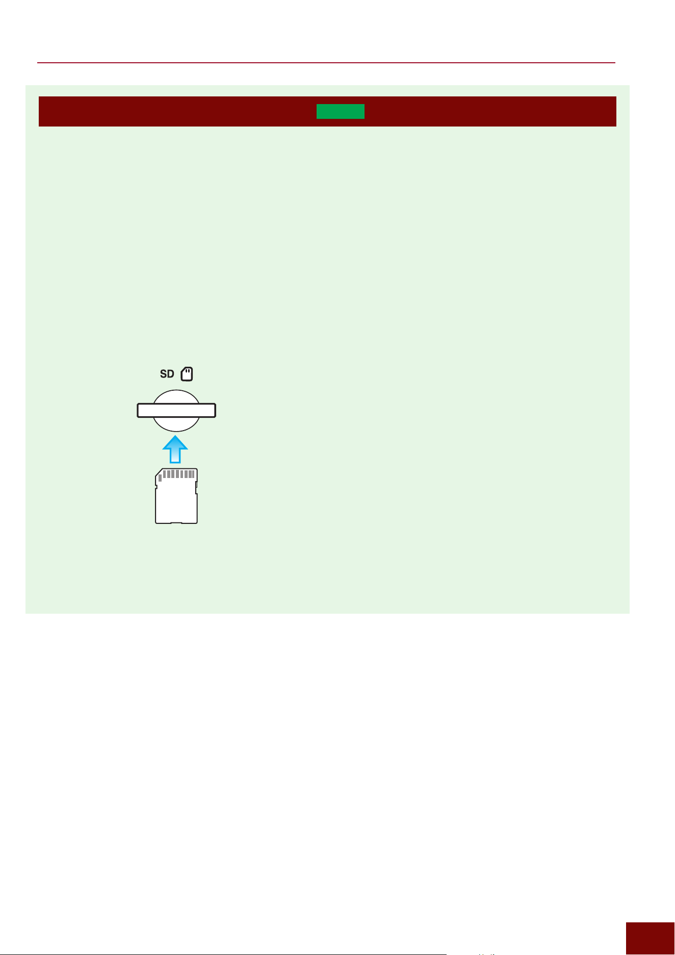
This product includes two types of USB terminals (Type-A and Type-C).
■ Precautions for Using the [USB TO HOST]
terminal
The [USB TO HOST] terminal (Type-C) is used to connect
this product to a computer, smart device, or other host
device. MIDI or audio communication between the host
device and application can be used to compose music. For
more information, refer to Pages 47 and 49.
• Prepare a USB cable appropriate for the connector shape
on the device being connected. However, note that,
depending on how it is connected, the connected device
might not function as a host device.
• If connecting to a smart device or computer, take the
following precautions to prevent damaging data in the event
the device malfunctions or stops functioning (hangs).
- Stop playing music with this product and close all
applications before turning this product off and on or
disconnecting and reconnecting a USB cable.
- Wait at least 6 seconds before turning this product off and
on or disconnecting and reconnecting a USB cable.
• If the smart device, computer, or this product stops
functioning, restart the application, smart device, and
computer, or turn this product off and on.
■ Precautions for Using the [USB TO DEVICE]
Terminal
The following devices can be connected to the Type-A USB
terminal.
• MIDI devices equipped with USB-MIDI function
• USB flash drives (except for devices such as USB hub,
mouse, and computer keyboard)
Connecting to a USB Flash Drive
• Insert the flash drive into the [USB TO DEVICE] terminal,
being careful of its proper vertical orientation.
• Do not connect or disconnect the USB flash drive during
playback, recording, or file operations (save, load, format,
etc.) or while accessing the USB flash drive. Doing so
could cause this product to stop or corrupt the USB flash
drive or data.
• Wait several seconds before connecting/disconnecting the
USB flash drive.
• Connect the flash drive directly to the unit, without using a
hub or extension cable.
• For a list of compatible USB flash drives, check
“Documents/Data” in the website below.
https://download.yamaha.com/
• The time required to save data to the USB flash drive or
load data from USB flash drive can vary depending on the
type of data or the status of this product.
Formatting USB Flash Drives
Using this product for formatting USB flash drives is
recommended. USB flash drives formatted using other
equipment might not function properly in this product. For
information about formatting, refer to Page 207.
NOTICE
Formatting a USB flash drive will delete all data in the device.
Before formatting, confirm that the flash drive does not contain
any data that will be required.
Preventing Accidental Deletion of USB Flash Drive
Data
Some USB flash drives include a write-protect function
that prevents accidentally deleting data. Use that function
to write-protect any valuable data stored in the device to
prevent it from being overwritten. Conversely, make sure
USB flash drive write-protections have been disabled before
saving or otherwise changing data on the device.
Turning Off Power While a USB Flash Drive is
Connected
Before turning off the power, confirm that the USB flash drive
is not being accessed, such as for playback, recording, or
file operations (save, load, format, etc.). Not doing so could
corrupt the USB flash drive or data.
Connecting MIDI Devices
MIDI devices can be connected to the USB terminals on this
product. For more information, refer to the following pages.
• Connecting a MIDI device
to the [USB TO HOST] terminal
_
Page 47
• Connecting a MIDI device
to the [USB TO DEVICE] terminal
_
Page 44
EAD50 EAD20 User Guide
15
Panel Controls and Functions
Precautions for Using SD Cards (
EAD50
only)
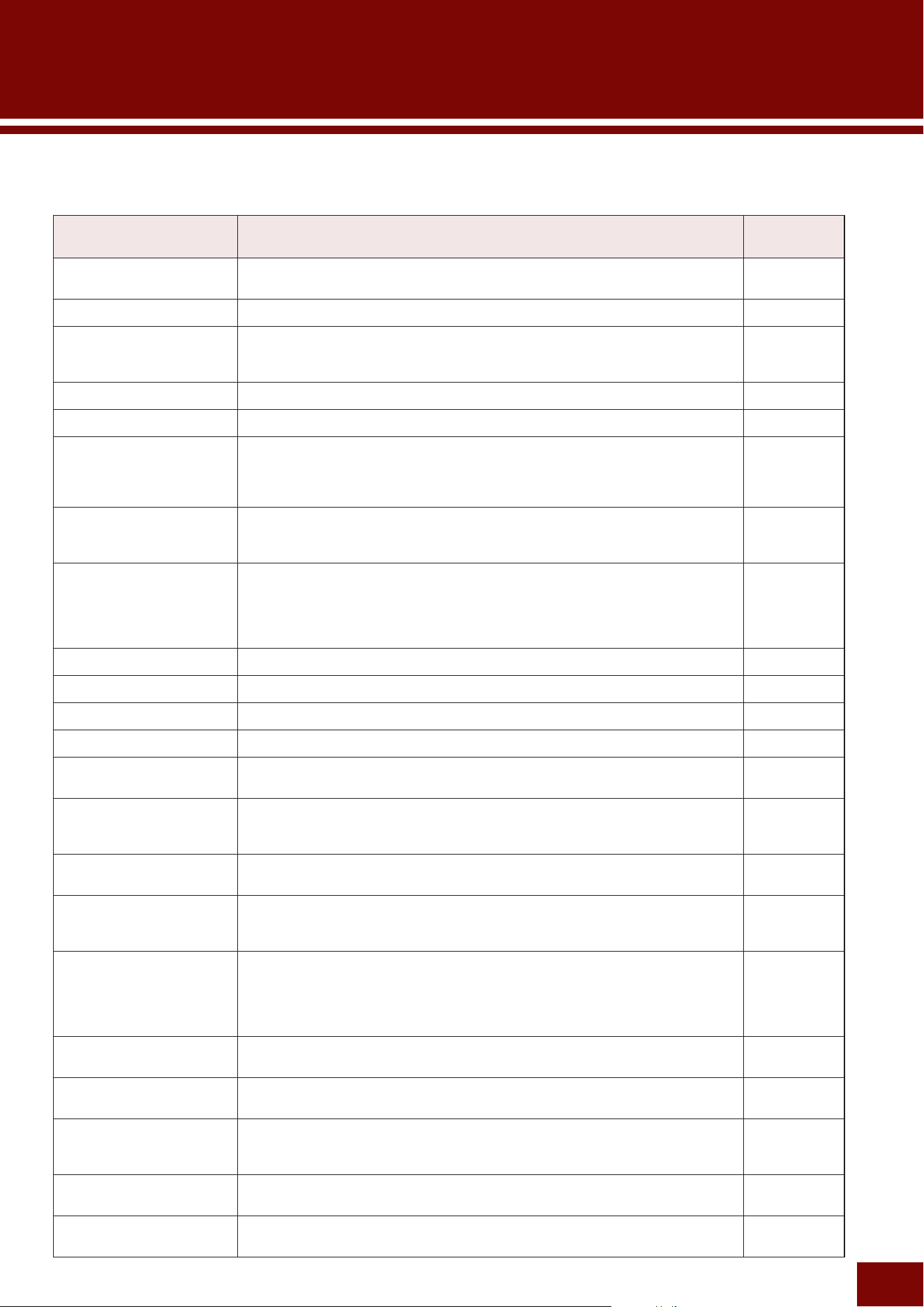
This product includes a slot for inserting an SD card or SDHC card, which can be used to save data created on this product.
Compatible Cards
This product supports using SD and SDHC memory cards.
Use cards with a suitable storage capacity.
Inserting SD Cards
• Insert SD cards with the metal terminal surfaces oriented
upward, as illustrated below.
• Do not connect or disconnect SD cards during playback,
recording, or file operations (save, load, format, etc.) or
while accessing the SD card. Doing so could cause this
product to stop or corrupt the SD card or data.
• Wait several seconds before connecting/disconnecting SD
cards.
Formatting SD Cards
Using this product to format SD cards is recommended. SD
cards formatted using other equipment might not function
properly in this product. For information about formatting,
refer to Page 207.
NOTICE
Formatting an SD card will delete all data stored in the card.
Before formatting, confirm that the flash drive does not contain
any data that will be required.
Preventing Accidental Deletion
Some SD cards include a lock switch that prevents
accidentally deleting data. If the card contains valuable
data, enable the lock switch to prevent the data from being
overwritten. Conversely, check to make sure the lock switch
is unlocked before using the card to save data.
Turning Off Power While an SD Card is Inserted
Before turning off the power, confirm that the SD card is not
being accessed, such as for playback, recording, or file
operations (save, load, format, etc.). Not doing so could
corrupt the SD card or data.
EAD50 EAD20 User Guide
16
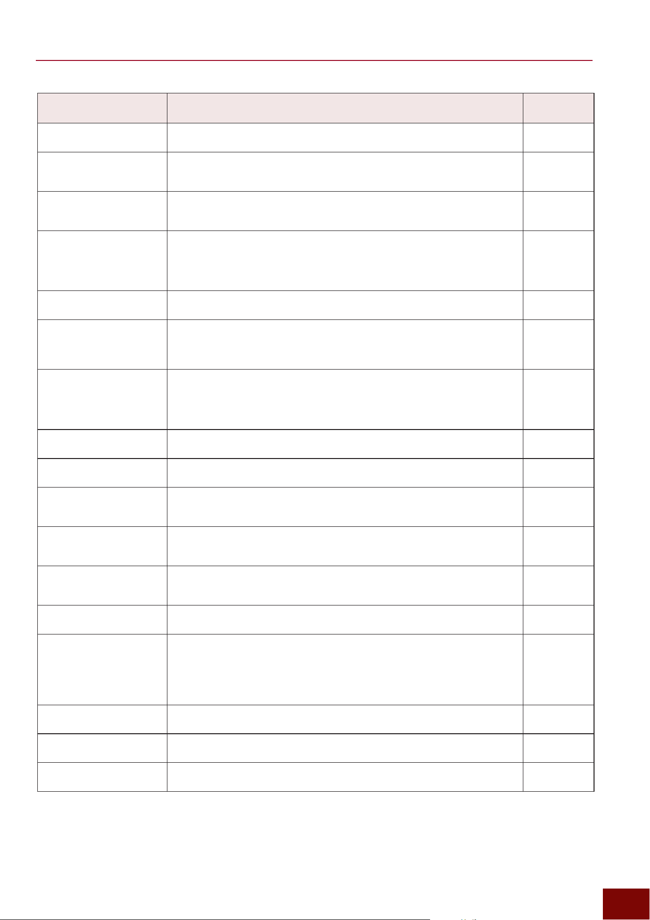
This lists terminology specifically related to acoustic or electronic drums and provides simple explanations for key terminology
that can be viewed while reading this User Guide.
Term Explanation
Reference
destination
Audition (Preview)
This sets the velocity of the preview sound (audition) produced by pressing the [F3]
button in the Trigger Input Select screen (Page 63).
Page 63
Bow
The broad area between the cymbal cup and edge areas. Page 23
Channel
A unit constructing various sounds played by this product. This product includes
channels for mic sounds (Mic1–5), Trigger sounds (Kick, Snare, and Trig3–22), and
audio.
Page 46
Closed Bow (ClBw)
Hitting the bow area of a hi-hat cymbal with the foot controller pressed. Page 24
Closed Edge (ClEg)
Refers to hitting the edge of a hi-hat cymbal with the foot controller pressed. Page 24
Closed Rim Shot
For acoustic drums, this technique refers to using wrist control to hit the rim while
muting the drum with a hand placed on the center area of the drum hitting surface
(head). For electronic drum pads, it involves hitting only the closed rim area without
touching the head.
Page 120
Cross-Stick (Xstick)
It has the same definition as “closed rim shot.” Page 80,
120, and
142
Crosstalk
The term “crosstalk” refers to resonance or interference between different pads,
which can generate a Trigger signal from a separate pad when an electronic drum
pad is hit (including from acoustic drums with a drum Trigger attached). For EAD
and DTX series drums, crosstalk can be prevented by not emitting Trigger signal
sounds that are lower than the specified value.
Page 122
Cup
The small raised portion at the center of cymbals. Page 23
Drum Kit
Same definition as “Kit.” Page 23
Edge
Refers to the outer edge area of drums and cymbals. Page 23
Foot-Closed
Closing the hi-hat cymbals together by pressing the hi-hat pedal. Page 124
Foot-Splash
Technique for producing a fluctuating orchestral cymbal-like sound with the hi-hat by
pressing and immediately releasing the hi-hat pedal.
Page 124
Head
On an acoustic drum, it refers to the membranes stretched across the hitting
surface and rear surface of the drum, which generate a sound when hit with a
stick. Those same surfaces are also referred to as a head on electronic drum pads.
–
Hi-Hat Cymbal
Percussion instrument with two cymbals stacked on a specialized stand with a
pedal that can open (spread apart) or close (hit together) the two cymbals.
–
Inst
An Inst is the specific instrument sound produced when a specific pad is hit, where
one Inst sound is assigned to each pad. They were also referred to as “Voice sets”
for previous DTX series models.
Page 23
Kit
The set of percussion instrument sounds (Insts) assigned to various pads in an
electronic drum set is referred collectively as a “Kit.” For typical electronic drums,
the preferred Kit can be selected based on the performance scenario or “Scene.”
For this product, a “Kit” is configured within a “Scene,” so that selecting the Scene
also results in selecting the Kit.
Page 23
Layers
Layers are parameter constraints assigned to Voices. EAD modules offer four
layers available for assigning Voices to each electronic drum Trigger Input Source.
Page 134
Live Set
In terms of this product, a Live Set is the function for preparing a sequence of
Scenes for successive execution during a performance.
Page 185
Membrane Switch
A component installed in some electronic drum pads. For example, if installed
inside a single-piezo pad with multiple zones, these switches are used to
differentiate between zones based on the voltage detected when the pad is hit.
Page 26
Open Bow (OpBw)
Refers to hitting the bow area of a hi-hat cymbal without stepping on a foot
controller at all.
Page 24
Open Edge (OpEg)
Refers to hitting the edge of a hi-hat cymbal without stepping on a foot controller at
all.
Page 24
Glossary
EAD50 EAD20 User Guide
17
Glossary
Term Explanation
Reference
destination
Open Rim Shot
Refers to the technique of simultaneously hitting both the head and rim of a drum,
such as a snare drum, with a stick.
Page 120
Pad
The pads are the electronic drum components that are hit. The Trigger signals
generated by hitting pads are used to produce electronic drum sounds (Voices)
located in the electronic drum tone generator.
Page 23
Pad Lock
When configuring Trigger Input-related settings for this product, the applicable
Trigger Input can be selected by hitting the corresponding pad. The pad lock
function prevents the applicable Trigger from changing when a pad is hit.
Page 63
Pad Type
A pad type is a pre-adjusted set of Trigger Input signals or other settings that are
configured to ensure an optimal sound is always produced when an electronic
drum pad is hit. Because the tone generator can be connected to a wide variety of
pads, such as kick, snare, tom, and cymbal pads, the pad types best suited to the
characteristics of each pad are selected.
Page 119
Parts
Individual units, corresponding to 1 electronic drum pad (Inst), that make up
electronic drum tone generators, where 1 Inst = 1 Trigger Input = 1 Part.
Page 131
Piezoelectric Element
These sensor devices are mounted inside electronic drum pads. These sensors
determine the volume, quality, and tone of waveforms detected, based on how
hard and where the pads are hit. Single-piezo or multi-piezo pads are available,
equipped with a different number of piezoelectric elements.
Page 27
Real Ambience
Some electronic drum Insts (Voices) are composed of two types of waveforms, one
recorded on-mic (sound of the instrument itself) and the other recorded off-mic
(with reverb). This product includes a parameter called “Real Ambience” that can
be used to configure Voices by adjusting the balance between those two types of
waveforms.
Page 29
Rim
The rim is the frame used to fasten the hitting surface (head) on drums, such as on
snare drums.
Page 23
Scene
A group of settings configured for playing drums in various specific situations and
that can be recalled with a single button action is referred to as a “Scene.”
Page 90
Talk
This product includes a setting for changing the purpose of connected
microphones from capturing drum performances to capturing performers talking.
That is displayed “Talk” on the screen.
Page 112
Trigger Input
Units of constraints for Trigger signals input to the tone generator module. They
are configured from multiple Trigger Input Sources. One Inst is assigned to each
Trigger Input.
Page 21
Trigger Input Source
This is the minimum unit of constraints for Trigger signals input to the tone
generator module. They are configured from four layers. One Voice is assigned per
layer, so that up to four Voices can be assigned to each Trigger Input Source.
Page 24
Trigger Sensor
This is the sensor used to acquire Trigger signals, with a piezoelectric element
serving as the sensor for electronic drum pads and this product.
–
Trigger signal
Signal generated from hitting an electronic drum pad. It communicates the force
and location of the hit to the tone generator module for the electronic instrument.
Then the tone generator module produces an electronic sound (Voice) based on
the Trigger signal received. Electronic sounds can also be produced based on
Trigger signals generated from acoustic drum performances with a Trigger sensor
attached to an acoustic drum.
Page 63
Trigger Sound
For convenience, the electronic sounds (Voices) produced based on Trigger
signals are referred to as Trigger sounds.
Page 23
Voices
This refers to the individual electronic sounds (Trigger sounds) included in Inst
sounds assigned to electronic drum pads.
Page 23
Zone
"Areas on electronic drum pads where different Trigger signals can be emitted.
1-zone, 2-zone, and 3-zone pads are available."
Page 26
EAD50 EAD20 User Guide
18
What is “EAD”?
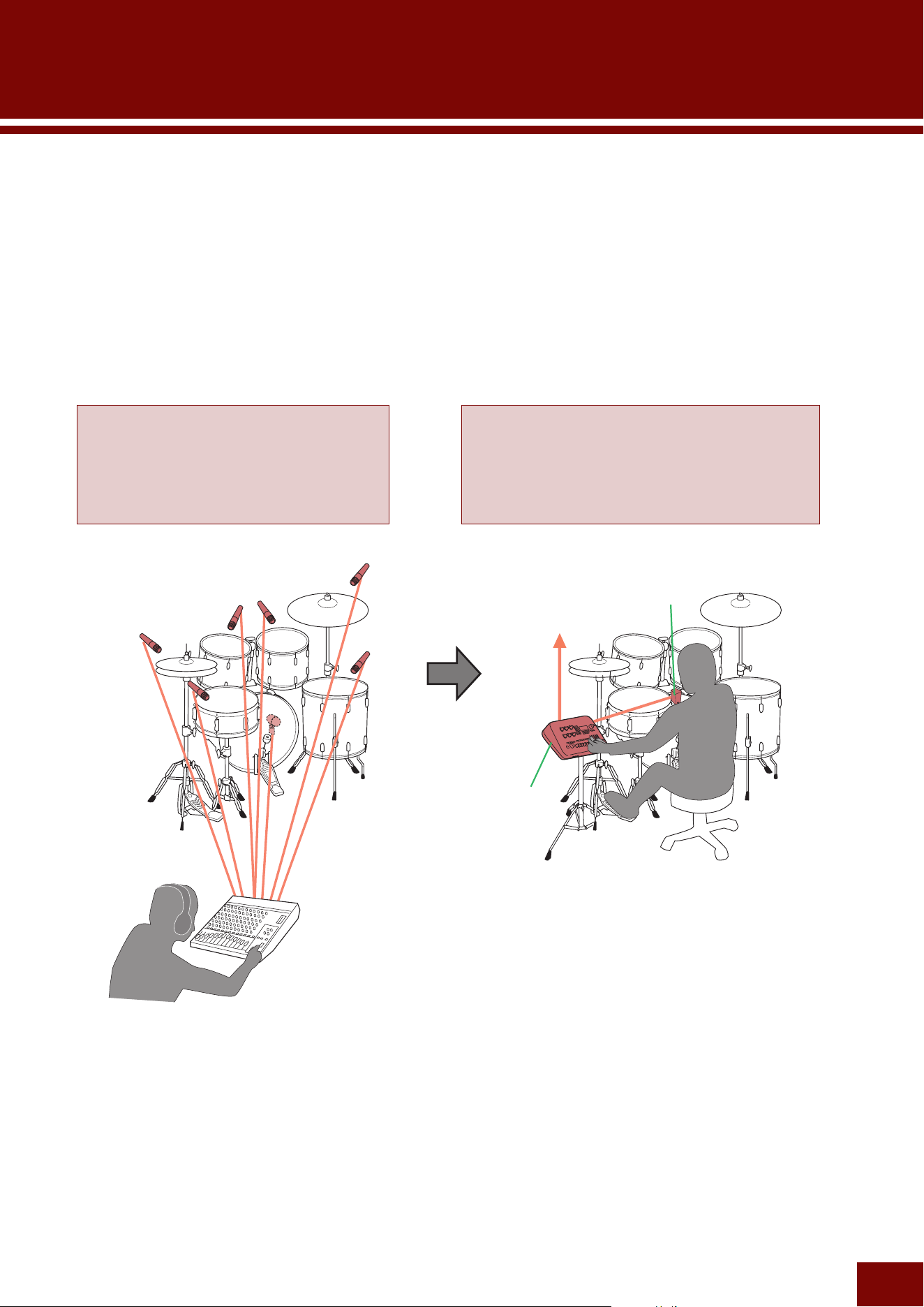
EAD modules are devices that create sound based on two types of signals received from sensors mounted on
acoustic drums, sound input via a mic jack, and signals input via a Trigger jack.
• The sound input via a mic jack refers to the audio signal produced by hitting acoustic drums.
• The input signal via a Trigger jack refers to Trigger signals generated by Trigger sensors, mounted to acoustic
drums or electronic drum pads, when they are hit. Based on those signals, this product produces corresponding
electronic drum sounds (Voices) included in the module.
By mixing those both acoustic and electronic sounds with Effect settings, volume adjustments, and so on, the
module can enhance personal drum performances to produce the sound preferred.
Main unit
Conventional Setup: Without EAD
A mic is set up for each instrument in the drum
set and the sounds input from each mic are
then balanced by a mixing engineer making
mixer adjustments at the live performance
venue.
Setup with EAD
Performance sounds can be captured with one
sensor unit, without setting up mics for individual
instruments. Also, either an engineer or performer
can adjust the balance themself.
Sensor unit included
with this product
To PA mixer
EAD50 EAD20 User Guide
19
What is “EAD”?
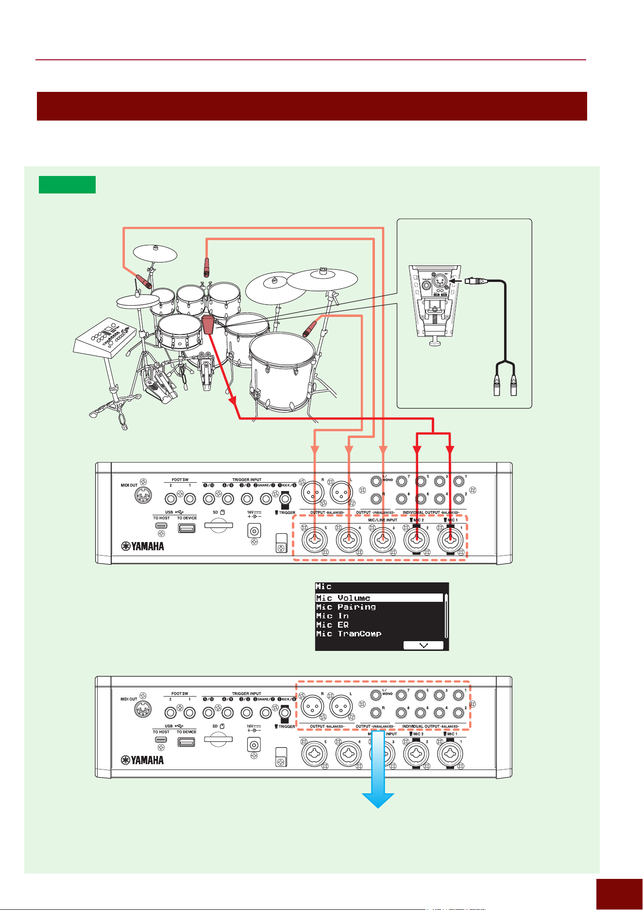
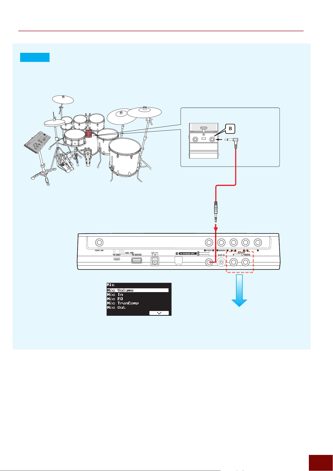
Acoustic Drum Section (with Microphone Inputs)
This section picks up the sound of the acoustic drums with microphones, and then makes mixing such as the volume balance
adjustment and Effect settings to finalize the total sound.
EAD50
Inputs (Page 41)
Outputs (Page 45)
[MIC/TRIG]
"
[F3] Setting
"
Mic
Acoustic drum set
Included Sensor Unit
DSU50
MIC jack
5-pin stereo
XLR cable
for microphones
EAD50 EAD20 User Guide
21
What is “EAD”?
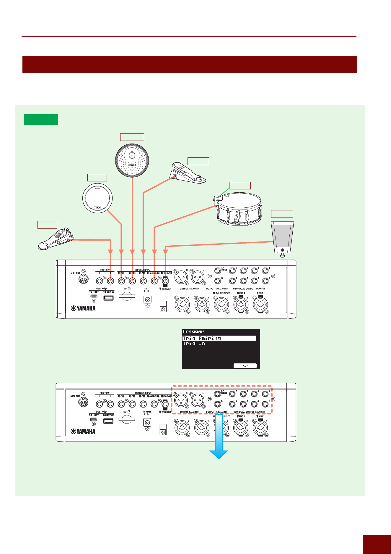
Electronic Drum Section (with Trigger Inputs)
This section generates the electronic sound (Voice) from the Trigger Signal generated by playing the acoustic drum equipped
with a Sensor Unit or electronic drum pad, and then makes mixing such as the volume balance adjustment and Effect settings
to finalize the total sound.
EAD50
Outputs (Page 45)
Included
Sensor Unit
DSU50
TRIGGER jack
KU100
PCY100
HH65
Hi-hat controller
[MIC/TRIG]
"
[F3] Setting
"
Trigger
XP80
DT50S
EAD50 EAD20 User Guide
23
Generating Trigger Sounds (Kits, Insts, and Voices)
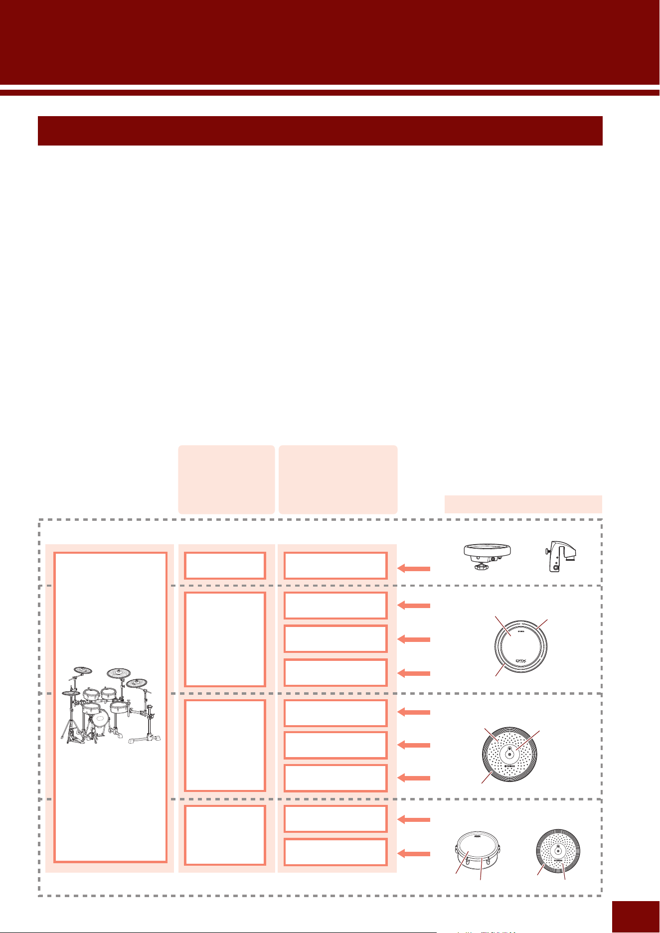
Trigger sounds (Kits, Insts, and Voices) are generated based on Trigger signals input to the EAD unit, such as by hitting a drum
pad, as described below.
Kits
The set of percussion instrument sounds (Insts) assigned to various pads in an electronic drum set is referred collectively as a
“Kit.” For EAD modules, Kits are integrated into Scenes, so Kits are normally selected by selecting a Scene.
Inst
An Inst is the specific instrument sound produced when a specific pad is hit, where one Inst sound is assigned to each pad. To
change the sound of a pre-installed Kit, the Inst settings (for each pad) are changed for each Trigger Input jack. Any Inst can
produce a Voice with any electronic drum tone generator part.
Voices
This refers to the individual electronic sounds included in Inst sounds assigned to electronic drum pads. To change the sound in
more detail after selecting an Inst, the Voice settings are changed for each Trigger Input Source (each pad zone). To incorporate
sounds not available in this product, user-specified Voices (User Voices) can be created, such as by Sampling or loading an
audio file from a USB flash drive, and then assigning it to a corresponding pad.
• 1 pad (with multiple zones) = 1 cable = 1 Trigger Input = 1 Inst = 1 set of up to 4 layered Voices × the number of zones = 1 electronic drum
tone generator part
• 1 zone = 1 Trigger Input Source = 1 set of layered Voices
How to Configure Trigger Inputs
Pad area
Bow area
B-rim area
Cup area
[MIC/TRIG]
"
[F3] Setting
"
Kit
"
Inst
[MIC/TRIG]
"
[F3] Setting
"
Kit
"
Voice
Kit
Inst
Max. 4 Voices*
Max. 4 Voices*
Max. 4 Voices*
Max. 4 Voices*
Max. 4 Voices*
Max. 4 Voices*
Max. 4 Voices*
Max. 4 Voices*
Max. 4 Voices*
Inst
Inst
Inst
Trigger
signals
Pads
1-zone pads
(monaural pads)
3-zone pads
(XP80, etc.)
3-zone pads
(PCY135, etc.)
Multi-piezo pads
(XP125SD-X, etc.)
2-zone pads
(RHH135, etc.)
A-rim area
Edge area
(XP70, etc.)
(DT50K, etc.)
Rim area
Head area
Edge area
Bow area
Trigger Inputs Trigger Input Source
EAD50 EAD20 User Guide
24
How to Configure Trigger Inputs
How to Configure Trigger Signal Inputs
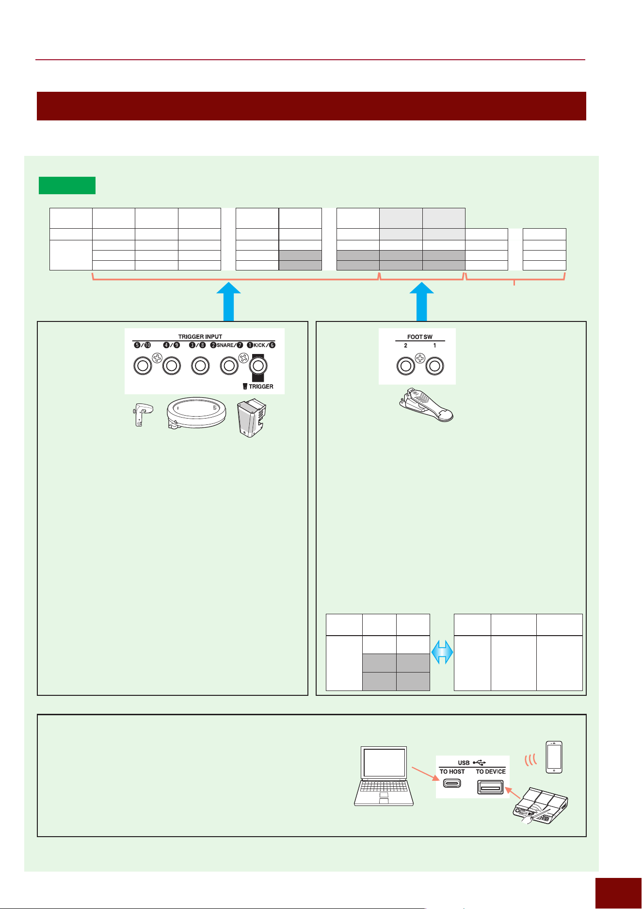
The electronic tone generator in this product can process Trigger Inputs.
EAD50
Integrated Trigger Input
■ Trigger Signals Input via Trigger Input Jacks
This product receives Trigger signals from electronic drum
pads and other devices connected to this product. All
Trigger Input jacks are stereo jacks that can receive up
to 2 types of Trigger Inputs via one cable (and one jack).
That is why each jack name comprises two digits, such as
“
r
/
o
.”
The following screens are used to specify settings, such
as the types of pads to connect and what input mode to
use for Trigger signals.
[MIC/TRIG]
"
[F3] Setting
"
Trigger
"
Trig Pairing
[MIC/TRIG]
"
[F3] Setting
"
Trigger
"
Trig In
"
Pad
■ Trigger Signals Input from Foot Switch Jacks
Trigger signals are generated based on signals input from
a foot switch or foot controller connected to this product.
Use the following screens to specify necessary settings,
such as for selecting the pads (Trigger signals) to be
controlled by those devices.
[MIC/TRIG]
"
[F3] Setting
"
Trigger
"
Trig In
"
Foot Sw1, Foot Sw2
"
HH Trig In
If HH Trig In = Off.
If any setting other than HH
Trig In = Off.
Emits Voices Foot1 and Foot2.
The performance technique is controlled
assuming HH1 and HH2 are hi-hat cymbal
Voices.
Trigger
Inputs
Foot1 Foot2
Trigger
Inputs
HH1 HH2
Trigger
Input
Source
Foot1Src Foot2Src
Trigger
Input
Source
• HH1OpBw
• HH1OpEg
• HH1ClBw
• HH1ClEg
• HH1FtCl
• HH1FtSp
• HH2OpBw
• HH2OpEg
• HH2ClBw
• HH2ClEg
• HH2FtCl
• HH2FtSp
■ Trigger Signals Generated Based on MIDI Inputs (All
Trigger Inputs)
All Trigger signals can be controlled by MIDI. If a note number
matching any of the note numbers (Num) specified for Layer A of
respective Trigger Inputs on the following screen is input by MIDI,
then a Trigger signal is generated and the sound is produced.
[MIC/TRIG]
"
[F3] Setting
"
Kit
"
Voice
"
Voice MIDI
"
Note 1
Trig11 – Trig22 only
support MIDI inputs
Connector No.
q w e
....
t y !0
FOOT SW 1 FOOT SW 2
Trigger Inputs
Kick Snare Trig3 Trig5 Trig6 .... Trig10
Foot1 Foot2
Trig11 .... Trig22
Trigger Input
Source
KickSrc1 SnareSrc1 Trig3Src1 Trig5Src1 Trig6Src1 Trig10Src1 Foot1Src Foot2Src Trig11Src1 Trig22Src1
KickSrc2 SnareSrc2 Trig3Src2 Trig5Src2 Trig11Src2 Trig22Src2
KickSrc3 SnareSrc3 Trig3Src3 Trig5Src3 Trig11Src3 Trig22Src3
Bluetooth
DAW
EAD50 EAD20 User Guide
25
How to Configure Trigger Inputs
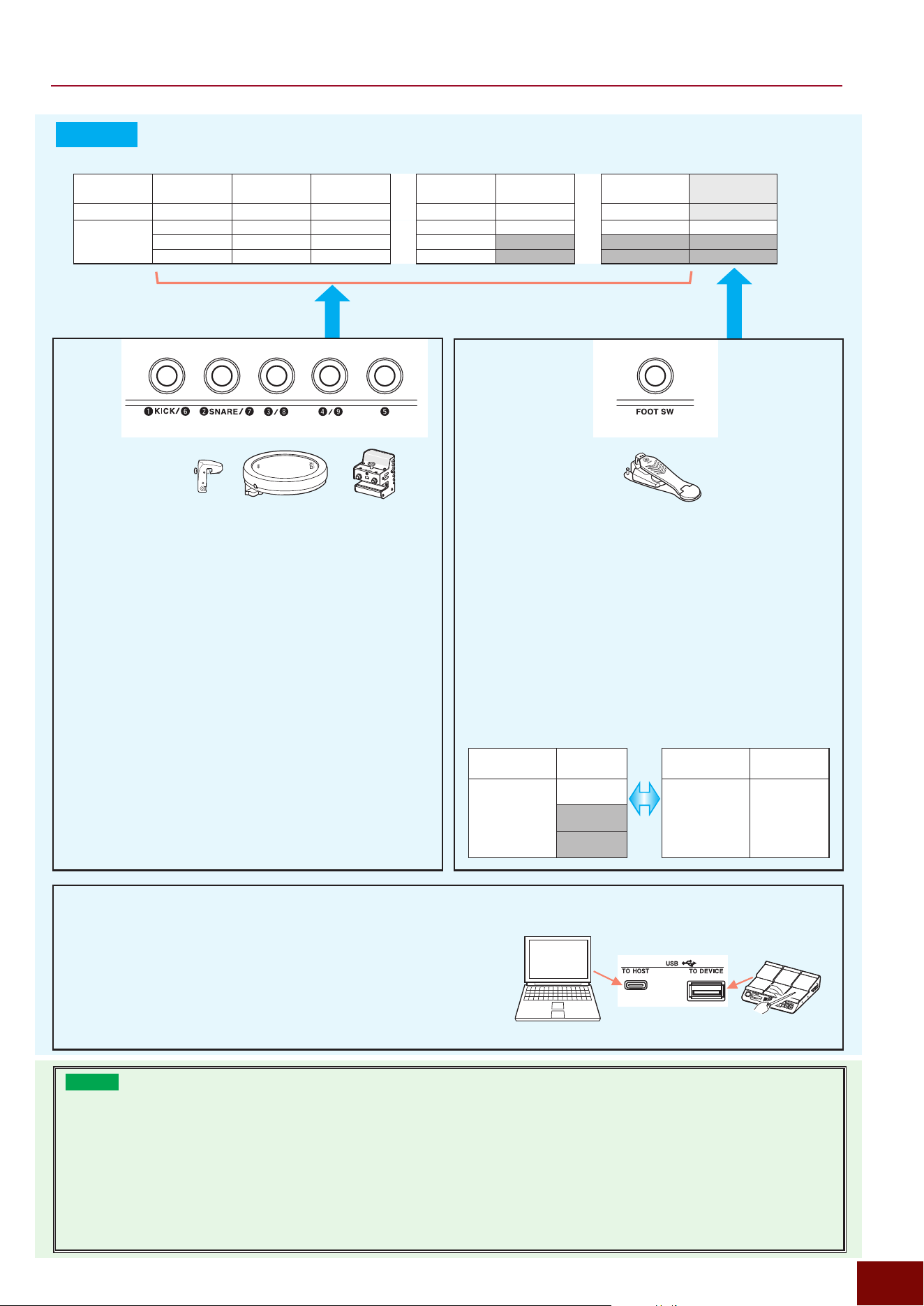
EAD20
Connector No.
q w e t y o
FOOT SW
Trigger Inputs
Kick Snare Trig3 .... Trig5 Trig6 .... Trig9
Foot
Trigger Input
Source
KickSrc1 SnareSrc1 Trig3Src1 Trig5Src1 Trig6Src1 Trig9Src1 FootSrc
KickSrc2 SnareSrc2 Trig3Src2 Trig5Src2
KickSrc3 SnareSrc3 Trig3Src3 Trig5Src3
■ Trigger Signals Input via Trigger Input Jacks
This product receives Trigger signals from electronic drum
pads and other devices connected to this product. All
Trigger Input jacks except
t
are stereo jacks that can
receive up to 2 types of Trigger Inputs via one cable (one
jack). That is why each jack name comprises two digits,
such as “
r
/
o
.”
The following screens are used to specify settings, such
as the types of pads to connect and what input mode to
use for Trigger signals.
[MIC/TRIG]
"
[F3] Setting
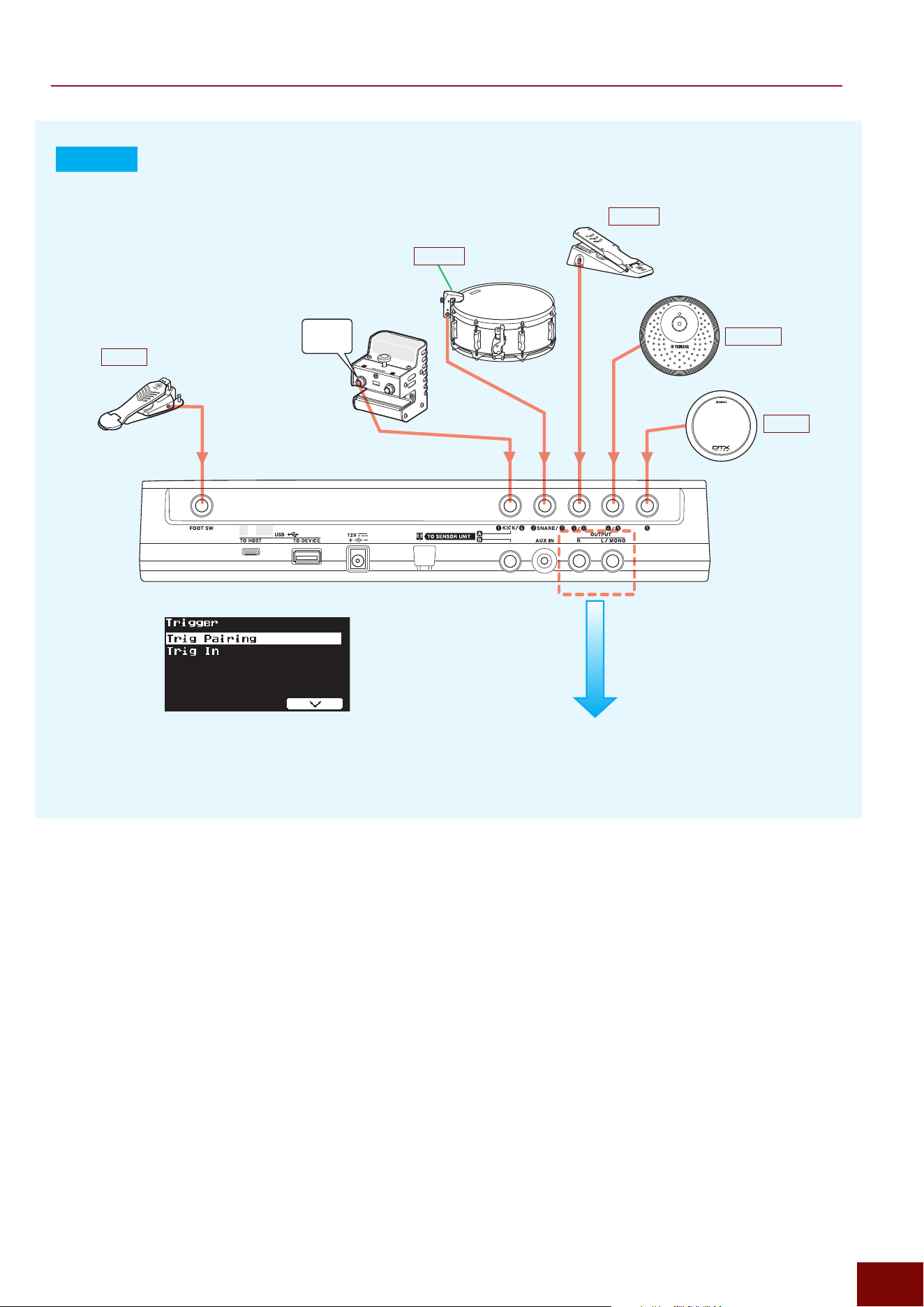
"
Trigger
"
Trig Pairing
[MIC/TRIG]
"
[F3] Setting
"
Trigger
"
Trig In
"
Pad
■ Trigger Signals Input from Foot Switch Jacks
Trigger signals are generated based on signals input from
a foot switch or foot controller connected to this product.
Use the following screens to specify necessary settings,
such as for selecting the pads (Trigger signals) to be
controlled by those devices.
[MIC/TRIG]
"
[F3] Setting
"
Trigger
"
Trig In
"
Foot Sw1, Foot Sw2
"
HH Trig In
If HH Trig In = Off. If any setting other than
HH Trig In = Off.
Generates
Foot
Voices.
It is used to control performances assuming
HH
Voices are from a hi-hat cymbal.
Trigger Inputs
Foot
Trigger Inputs
HH
Trigger Input
Source
FootSrc
Trigger Input
Source
• HHOpBw
• HHOpEg
• HHClBw
• HHClEg
• HHFtCl
• HHFtSp
■ Trigger Signals Generated Based on MIDI Inputs (All
Trigger Inputs)
All Trigger signals can be controlled by MIDI. If a note number
matching any of the note numbers (Num) specified for Layer A of
respective Trigger Inputs on the following screen is input by MIDI,
then a Trigger signal is generated and the sound is produced.
[MIC/TRIG]
"
[F3] Setting
"
Kit
"
Voice
"
Voice MIDI
"
Note 1
DAW
EAD50
Integrated Trigger Input
The EAD50 and EAD20 are equipped with the Trigger Input functions indicated below.
• USB Trigger function that supports performances using other electronic drums by treating MIDI messages received via the [USB TO DEVICE]
terminal as Trigger Inputs.
• Equipped with input jacks that support both 2-zone and 3-zone pads.
• Enables switching between Paired/Separate Trigger Inputs.
In addition to the above, the EAD50 also includes the following functions referred to as Integrated Trigger Inputs.
•
A wider range of Trigger Input levels offers compatibility with non-Yamaha pads (Page 26).
•
The USB Trigger Link Function achieves virtual parts 11 to 22 that are input via the Trigger Input jacks indicated above (Page 24).
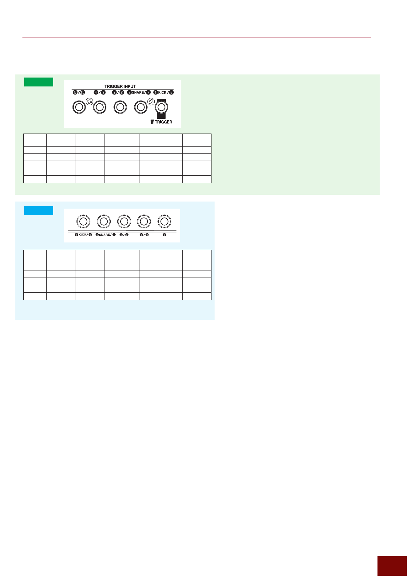
EAD50 EAD20 User Guide
26
How to Configure Trigger Inputs
■ Trigger Input Jack Specifications
EAD50
EAD50Jacks 1-zone pads
2-zone pads
3-zone pads
Multi-piezo pads
Pads supporting position
detection functionality (*2)
Non-Yamaha
Pads
q
/
y
✓
-
(*1)
✓
-
-
w
/
u
✓
-
(*1)
✓
- -
e
/
i
✓ ✓ ✓ ✓ ✓
r
/
o
✓ ✓ ✓ ✓ ✓
t
/
!0
✓ ✓ ✓ ✓ ✓
EAD20
EAD20Jacks 1-zone pads
2-zone pads
3-zone pads
Multi-piezo pads
Pads supporting position
detection functionality (*2)
Non-Yamaha
Pads
q
/
y
✓
-
(*1)
✓
- -
w
/
u
✓
-
(*1)
✓
- -
e
/
i
✓
-
(*1)
✓
- -
r
/
o
✓
-
(*1)
✓
- -
t
✓ ✓
- - -
■ Electronic Drum Pads Connectable to Trigger Input Jacks
z
1-Zone Pads
The simplest type of electronic drum pad, these generate only one type of Trigger signal from a piezoelectric element.
Consequently, they play the same Voice no matter where they are hit on the pad.
z
2-Zone and 3-Zone Pads
These pads are equipped with membrane switches that generate different Trigger signals depending on the pad location
(zone) hit. Consequently, they can play 2 or 3 different types of Voices.
z
Multi-Piezo Pads
These pads are equipped with multiple piezoelectric elements.
Compatibility with Non-Yamaha Pads (Integrated
Trigger Inputs)
Non-Yamaha pads can be connected to Trigger Inputs
e
/
i
,
r
/
o
, and
t
/
!0
by configuring the following settings.
• Connecting a kick Trigger pedal, bar Trigger pad, etc.
[MIC/TRIG]
"
[F3] Setting
"
Trigger
"
Trig In
"
Pad
"
Type=Kick Trigger Pedal (Category=Kick)
[MIC/TRIG]
"
[F3] Setting
"
Trigger
"
Trig In
"
Pad
"
Type=Bar Trigger Pad1, 2 (Category=Others)
• Connecting a non-Yamaha pad with a high output
level other than indicated above.
[MIC/TRIG]
"
[F3] Setting
"
Trigger
"
Trig In
"
Pad
"
Attenuator=On
(*1)
They cannot be used with 2 or 3-zone pads. If
connected, they will function as a 1-zone pad (only
the head will function for snare pads, only the bow
shot for cymbals, etc.).
(*2)
The EAD50 is equipped with position detection
functionality that can generate different signals for
different positions hit within the same zone on pads
that support the position detection function and that are
connected to jacks
e
/
i
,
r
/
o
, or
t
/
!0
. For example,
some 3-zone pads and multi-piezo pads support
position detection functionality.
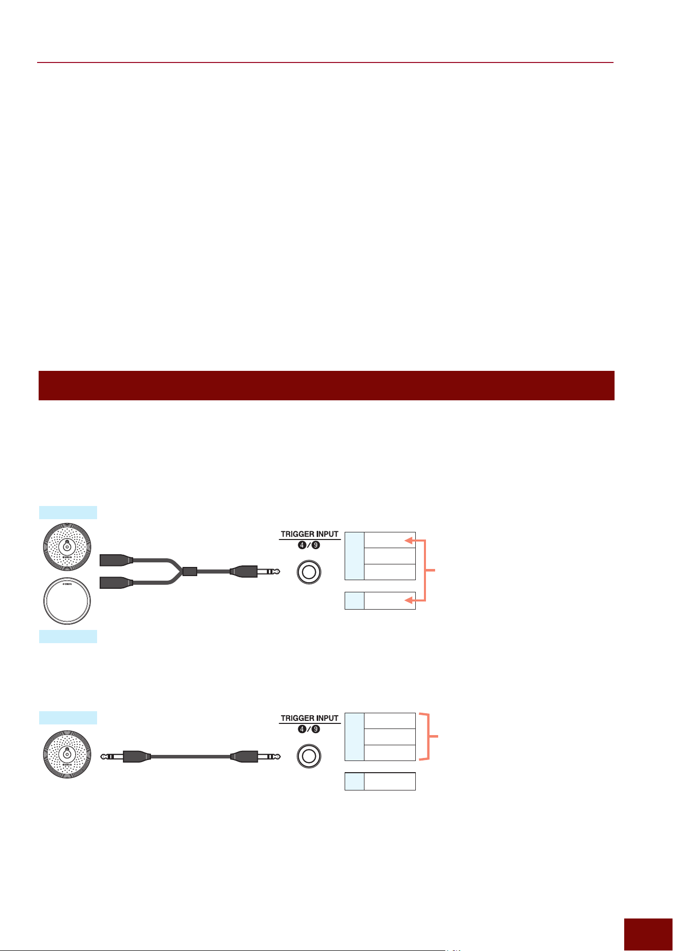
EAD50 EAD20 User Guide
27
How to Configure Trigger Inputs
■ Specifications for Generating Trigger Signals by Electronic Drum Pads
• Signals Generated by Piezoelectric Elements
Electronic drum pads are equipped with at least one piezoelectric element. When a pad is hit, the piezoelectric element reacts
to generate a Trigger signal. Pads equipped with 2 or more types of piezoelectric elements are referred to as multi-piezo or
2-piezo pads.
• Signals Generated by a Membrane Switch
Membrane switches are electronic components included in 2-zone and 3-zone pads. Hitting a particular location (zone) on the
pad activates the corresponding switch, which generates a Trigger signal for that location.
• Signals Generated by Position Detection Functionality
It detects different positions hit within the same zone. Since the positions are within the same zone, the same Voice is played,
but the sound naturally varies for different positions hit.
NOTE
Due to the wide variety of electronic drum pad specifications available, after connecting a pad, select the appropriate pad type on the screen
shown below.
[MIC/TRIG]
"
[F3] Setting
"
Trigger
"
Trig In
"
Pad
"
Type
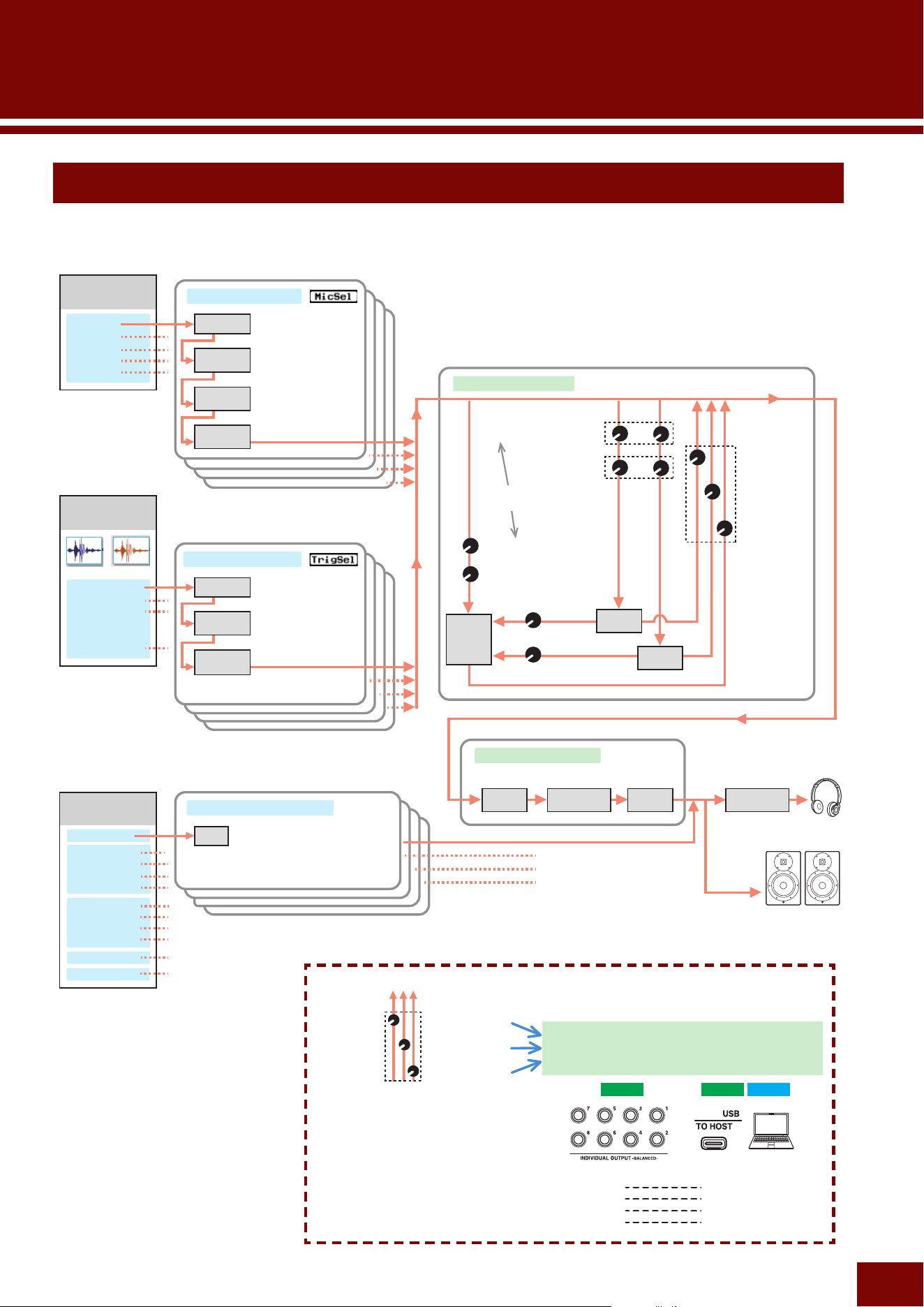
Trigger Input Mode
Trigger Input jacks with two numbers in the name, such as
“
r
/
o
”
, are designed to receive two monaural signals (stereo signal).
That means 2 types of Trigger signals can be input to this product via each cable (each connector). Accordingly, the input mode
can be changed for either of the two types of Trigger signals, to either input the signal from one Inst (pad) or input the signals
from separate Insts (pads).
Example of Setting [MIC/TRIG] "[F3] Setting "Trigger "Trig Pairing=Separate
Trigger signals from 3-zone pads are input to
the
r
system and then the signal from only the
main hitting surface of the 3 types (bow area for
cymbals or head area for snares/toms) is sent
to the tone generator (Trigger Input Source) for
playing the Voice.
Trigger signals from 1-zone pads are input to
the
o
system and then sent directly to the tone
generator (Trigger Input Source) for playing the
Voice.
Trigger signals from pads are input to the
r
system and then all 3 types are sent to the tone
generator (Trigger Input Source) for playing the
Voice. The
o
system is not used.
3-zone pads
3-zone pads
1-zone pads
Use a commercially available
Y-cable
r
Trig4Src1
Trig4Src2
Trig4Src3
o
Trig9Src1
r
Trig4Src1
Trig4Src2
Trig4Src3
o
Trig9Src1
Monaural headphone jack
Stereo headphone
jack
Stereo headphone
jack
Stereo headphone
jack
Monaural headphone jack
Trigger Input Source
Trigger Input Source
Example of Setting [MIC/TRIG] "[F3] Setting "Trigger "Trig Pairing=Paired
EAD50 EAD20 User Guide
28
Configuring Effects
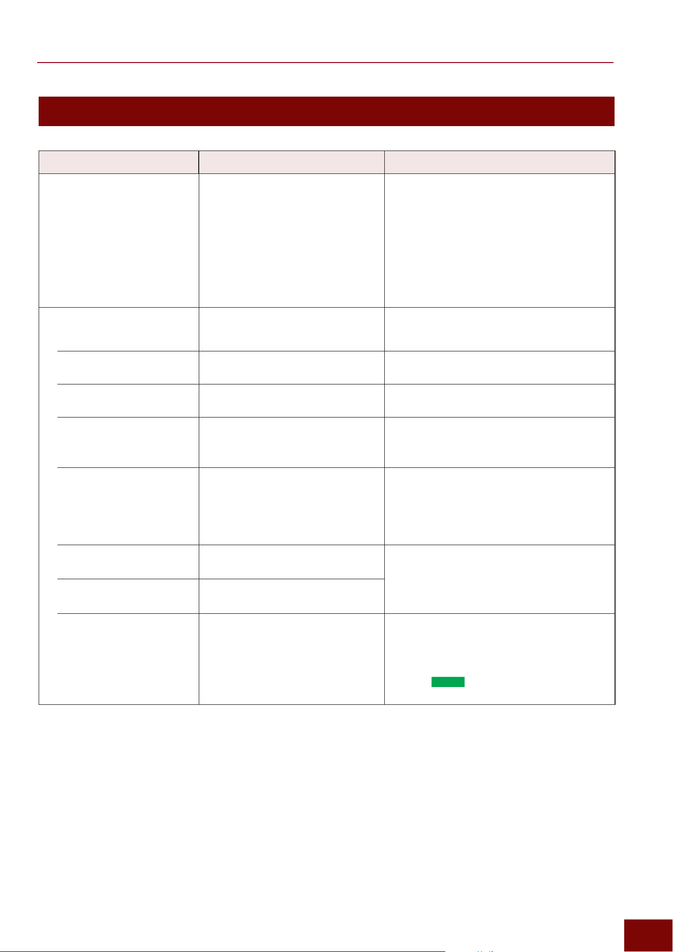
Diagram of Effects
NOTE
• For a block diagram, refer to Page 222.
• For more information about specific Effect block diagrams, see
from Pages 29 to 31.
• Whether or not to apply System Effects, Master Effects, or other
Effects can be specified for mic inputs and Trigger Inputs. For
more information, refer to Pages 115 and 131.
Master Effects
[MIC/TRIG]
"
[F3] Setting
"
Effect
[MENU]
"
Output
"
Phones EQ
Master FX Master EQ
Master
Compressor
Phones
EQ
Audio Channels
USB Audio 1/2
USB Audio 3/4
USB Audio 5/6
USB Audio 7/8
Recorder playback1
Recorder playback2
Looper playback
Sampling playback
Bluetooth Audio
*
4
AUX IN
Click
Audio Input-Specific EQ
EQ
[MENU]
"
Aux In
"
Aux In EQ
[MENU]
"
USB Audio
"
USB Audio EQ
[RECORDER]
"
[F3] Setting
"
Recorder EQ
[MENU]
"
Bluetooth
"
Bluetooth EQ
*
4
EAD50 only
Mic Input Channels*
2
(Acoustic Drums)
Mic1
Mic2
Mic3
Mic4
Mic5
Mic Input-Specific Insertion Effect
Parts EQ
Transient
Compressor
Insertion Effect
1
Insertion Effect
2
[MIC/TRIG]
"
[F3] Setting
"
Mic
"
Mic EQ
[MIC/TRIG]
"
[F3] Setting
"
Mic
"
Mic TranComp
[MIC/TRIG]
"
[F3] Setting
"
Effect
"
Ins1 Mic
[MIC/TRIG]
"
[F3] Setting
"
Effect
"
Ins2 Mic
*
2
The EAD50
includes 5 Mic Input
Channels, but the
EAD20 only includes
1 stereo channel.
System Effects
[MIC/TRIG]
"
[F3] Setting
"
Effect
Reverb
FX1
FX2
FX2
"
Send to Reverb
FX1
"
Send to Reverb
Reverb
"
Send All
Reverb
"
Send Mic, Send Trig
FX1
"
Send Mic, Send Trig
FX2
"
Send Mic, Send Trig
FX1
"
Send All
FX2
"
Send All
Send level can be set individually
for mic and Trigger Inputs.
FX1
"
Return
FX2
"
Return
Reverb
"
Return
*1 (Refer to the
bottom of this
page.)
Trigger Input Channel
(Electronic Drums)
Kick (tone generator part 1)
Snare (tone generator part 2)
Trig3 (tone generator part 3)
:
:
TrigXX (tone generator part XX)
*
3
Waveform Real Ambi
Parts EQ
Transient
Compressor
Insertion
Effect*
Trigger Input-Specific Insertion Effect
* Trig18 – 22 do not have Insertion Effects.
[MIC/TRIG]
"
[F3] Setting
"
Kit
"
Inst
"
Inst EQ
[MIC/TRIG]
"
[F3] Setting
"
Kit
"
Inst
"
Inst TranComp
[MIC/TRIG]
"
[F3] Setting
"
Effect
"
Ins Trig
*
3
EAD50
Kick, Snare, and Trig3–22
(tone generator parts 1 – 24)
EAD20
Kick, Snare, Trig3-9, Foot/HH
(tone generator parts 1 – 10)
1 Part = 1 Trigger Input = 1
Inst (1 Pad)
EAD50 EAD50 EAD20
[INDIVIDUAL OUTPUT] jacks
• IndivOut 1/2
• IndivOut 3/4
• IndivOut 5/6
• IndivOut 7/8
[USB TO HOST] terminal
• USB Audio Out 3/4
• USB Audio Out 5/6
• USB Audio Out 7/8
• USB Audio Out 9/10
FX1
"
IndivOut
FX2
"
IndivOut
Reverb
"
Return
*
1
The return sound for each System Effect can output individually.
[MIC/TRIG]
"
[F3] Setting
"
Effect
"
FX1, FX2, Reverb
"
EAD50: IndivOut
EAD20: USB AudOut
NOTE
• The EAD50 IndivOut setting is applied
to each USB audio channel according to
the links shown to the right.
• USB Audio Out 1/2 = Main Out L/R
EAD50 EAD20 User Guide
29
Configuring Effects
Configuring Effects
The Effects applied to the sound of this product are organized as below.
Effects Block Setting Screen Explanation
Real Ambience
[MIC/TRIG]
"
[F3] Setting
"
Effect
"
Real Ambi (Page 149)
Some electronic drum Insts (Voices) are composed
of two types of waveforms, one recorded on-
mic (sound of the instrument itself) and the other
recorded off-mic (with reverb). Real Ambience is
the function for adjusting the balance between on-
mic and off-mic sound.
NOTE
Insts (Voices) not composed of both on-mic and
off-mic waveforms cannot be balanced by Real
Ambience. For more details, check the Data List.
Channel-Specific Effects
Of all the channels for mic sounds and Trigger
sounds, these Effects are only applied to specific
channels.
Mic-Specific EQ
[MIC/TRIG]
"
[F3] Setting
"
Mic
"
Mic
EQ (Page 112)
These EQ are only applied to sounds input to
specific mic jacks.
Inst-Specific EQ
[MIC/TRIG]
"
[F3] Setting
"
Kit
"
Inst
"
Inst EQ (Page 128)
This EQ is only applied to specific electronic drum
pad Insts.
Mic-Specific Transient
Compressor
[MIC/TRIG]
"
[F3] Setting
"
Mic
"
Mic
TranComp (Page 114)
Applies Transient Effect (attack and release) and
Compressor together to each sound input via
microphone input jacks.
Inst-Specific Transient
Compressor
[MIC/TRIG]
"
[F3] Setting
"
Kit
"
Inst
"
InstTranComp (Page 129)
Applies Transient Effect (attack and release) and
Compressor together to each Inst in the current
Drum Kit.
Mic-Specific Insertion
Effect 1
[MIC/TRIG]
"
[F3] Setting
"
Effect
"
Ins1 Mic (Page 152)
Applies two systems of Insertion Effects individually
to sounds input via each mic input jack.
Mic-Specific Insertion
Effect 2
[MIC/TRIG]
"
[F3] Setting
"
Effect
"
Ins2 Mic (Page 152)
Trigger-Specific Insertion
Effect
[MIC/TRIG]
"
[F3] Setting
"
Effect
"
Ins
Trig (Page 153)
Applies
one system of Insertion Effects individually
to each Drum Kit Inst generated from the Trigger
Input.
NOTE
(Model
EAD50
only) This is not available for
Trig18–22.
EAD50 EAD20 User Guide
30
Configuring Effects
Effects Block Setting Screen Explanation
System Effects
These Effects are applied to all the channels for
mic sounds and Trigger sounds. Selectable Effect
types are the same for all parts, but the depth
they are applied can be changed for each part by
specifying a Send Level.
Sounds sent from respective parts to the Effect
block in accordance with the specified send level
are processed to create a wet sound. Then that
sound is returned to the original route via the same
return level for all parts and finished by mixing
it with a dry sound (sound without any Effects
applied).
System Effects are configured with the following
3 parallel blocks, with the selected type and
specified send level for each block.
NOTE
• It enables only wet sounds, configured in each
block, to be output independently (Pages 148
and 150).
• This specifies not only the sounds to be sent to
System Effects, but also sounds not to be sent
(dry). (Page 151)
Reverb
[MIC/TRIG]
"
[F3] Setting
"
Effect
"
Reverb (Page 147)
Reverb refers to the residual vibrational effects
(reverberation) used to simulate a live performance
at a concert hall or club.
FX1
[MIC/TRIG]
"
[F3] Setting
"
Effect
"
FX1
(Page 149)
These Effects include types, such as delay or
chorus.
FX2
[MIC/TRIG]
"
[F3] Setting
"
Effect
"
FX2
(Page 150)
Master Effects
These Effects are applied to all the channels for
mic sounds and Trigger sounds.
Master FX
[MIC/TRIG]
"
[F3] Setting
"
Effect
"
Master FX (Page 153)
Master Effects are applied to the overall sound
played on this product, excluding audio inputs.
Master Compressor
[MIC/TRIG]
"
[F3] Setting
"
Effect
"
Master Comp (Page 154)
These Compressor Effects are applied uniformly
to the overall sound played on this product,
excluding audio inputs.
Master EQ
[MIC/TRIG]
"
[F3] Setting
"
Effect
"
Master EQ (Page 154)
The EQ (equalizer) unit divides sound into multiple
frequency bands and raises or lowers the level
(gain) of those individual bands. The Master EQ is
an equalizer applied to the overall sound played
on this product, excluding audio inputs.
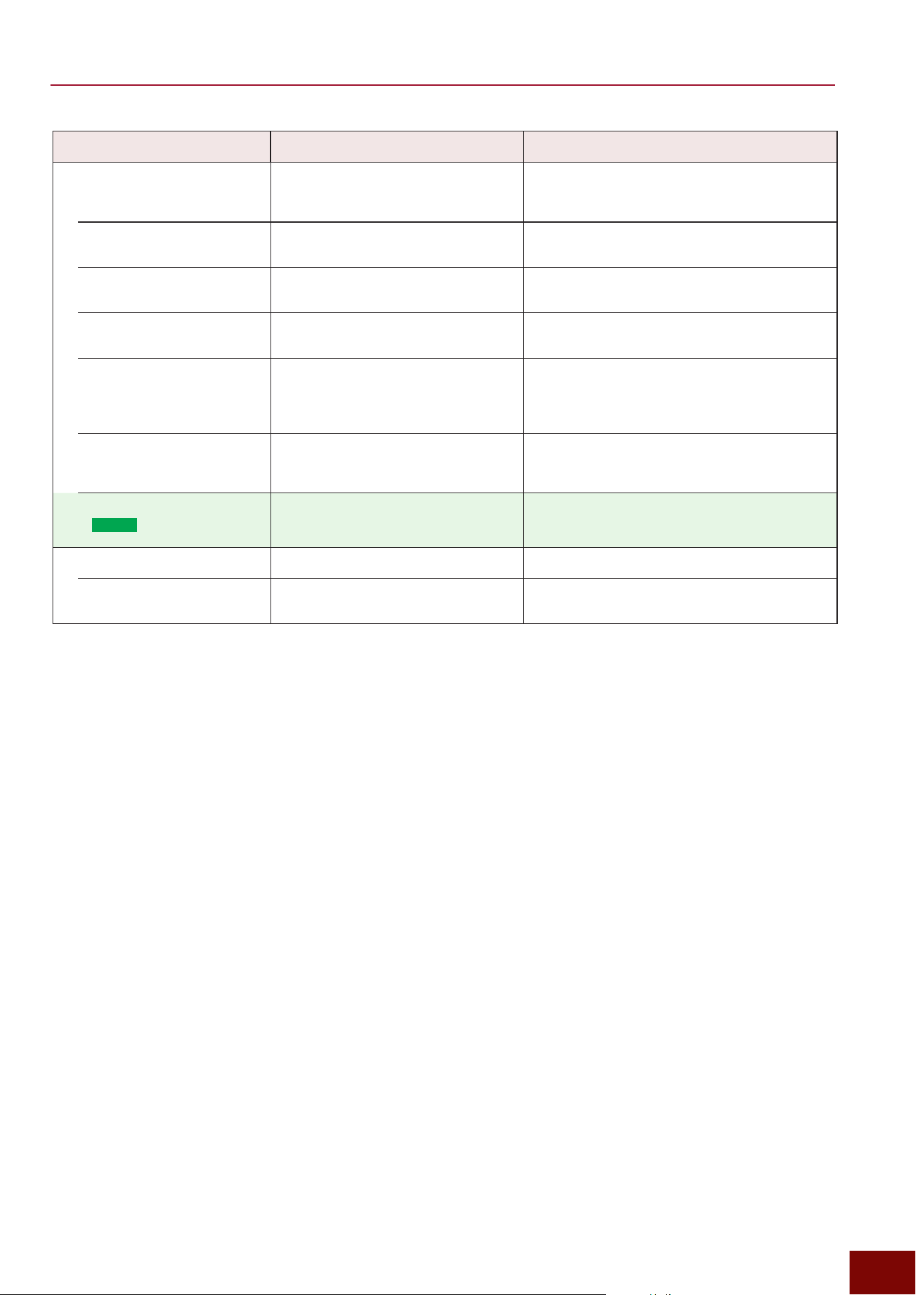
EAD50 EAD20 User Guide
31
Configuring Effects
Effects Block Setting Screen Explanation
Channel-Specific EQ
In addition to the Master EQ applied to the overall
sound, excluding audio inputs, EQ units are also
available for individual Inst, mic, or other channels.
Inst-Specific EQ
[MIC/TRIG]
"
[F3] Setting
"
Kit
"
Inst
"
Inst EQ (Page 128)
Refer to Page 29.
Mic-Specific EQ
[MIC/TRIG]
"
[F3] Setting
"
Mic
"
Mic
EQ (Page 112)
Refer to Page 29.
Inputs from the AUX IN
Jack
[MENU]
"
Aux In
"
Aux In EQ (Page
192)
This EQ is applied to sounds input to the [AUX IN]
jack.
Inputs from the [USB TO
HOST] terminal
[MENU]
"
USB Audio
"
USB Audio EQ (Page 196)
This allows specifying EQ settings individually for
each of the 4 pairs of stereo tracks (1/2, 3/4, 5/6,
and 7/8) of sounds input via the [USB TO HOST]
terminal.
Using the Recorder to
Playback Audio Recordings
[RECORDER]
"
[F3] Setting
"
Recorder
EQ (Page 170)
EQ settings can be specified separately for both
Recorder audio playback systems (Playback1 and
Playback2).
Input via Bluetooth
(
EAD50
only)
[MENU]
"
Bluetooth
"
Bluetooth EQ (Page 201)
Bluetooth EQ is applied to sounds input via
Bluetooth.
Headphones Sound EQ
Phones EQ
[MENU]
"
Output
"
Phones EQ (Page
190)
EQ settings can be applied to sounds heard via
headphones connected to the [PHONES] jack.
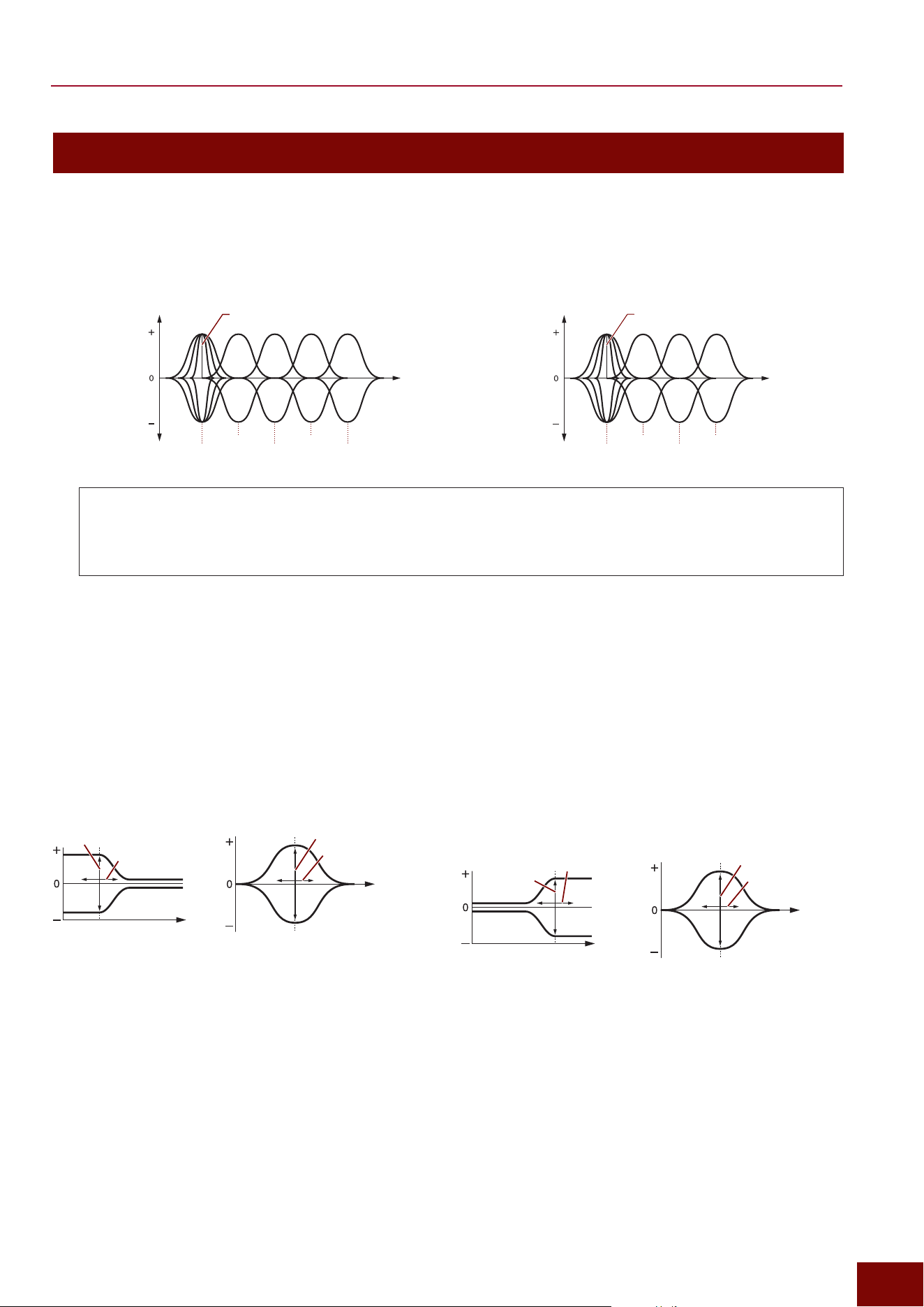
EAD50 EAD20 User Guide
32
Configuring Effects
Equalizer Shape
■ Equalizers (EQs)
An equalizer is a device that can boost or cut any of several frequency bands or adjust the Q factor (frequency characteristics)
to create the desired sound. The product is configured with 5 Master EQ bands and 4 channel-specific EQ (Page 31) bands.
z
EQ with 5 bands (Master EQ)
Gain
(Gain)
Band Range of 5 Bands
Q Factors (Frequency Characteristics)
Frequency
(Freq)
Low
MidLow
Mid
MidHigh
High
z
EQ with 4 Bands (Channel-specific EQ)
Gain
(Gain)
Band Range of 5 Bands
Q Factors (Frequency Characteristics)
Frequency
(Freq)
Low
MidLow
MidHigh
High
Q Factors (Frequency Characteristics)
For each EQ band, the Q factor sets the frequency range to which equalizing effects are applied. The larger the setting value,
the narrower the frequency range and the more quickly tone characteristics change. The smaller the value, the wider the
frequency range and the more gradually tone characteristics change.
■ Shelving vs Peak/Dip (PeakDip)
Adjustments to either raise or lower each frequency band, as shown above, are referred to as “PeakDip.” In contrast, adjustments
with a shape that increases or reduces sounds above or below a particular frequency are referred to as “shelving.” Selecting the
shelving shape toward the lower or higher frequency end applies the same effect as a low-pass or high-pass filter.
Shape of Low-Frequency End (Low Shape)
This selects one of the following shapes on all EQ (Pages
30 to 31) screens.
PeakDipLowShelving
Gain
Frequency
Frequency
Frequency
Gain
Frequency
Shape of High-Frequency End (High Shape)
This selects one of the following shapes on all EQ (Pages
30 to 31) screens.
PeakDip
Frequency
Gain
Frequency
HighShelving
Gain
Frequency
Frequency
■ Filter
This product achieves the Effect of a high-pass filter (HPF) and low-pass filter (LPF) by the following methods.
• The HPF is equipped with independent filters with relevant settings specified on the EQ setting screen for the four bands excluding the
Phones EQ.
• The LPF is achieved using the EQ high frequency band, with relevant settings specified by the “High Shape” setting on the EQ setting
screen for the four bands excluding the Phones EQ.
Both can be set via the EQ Settings screen for respective channels.
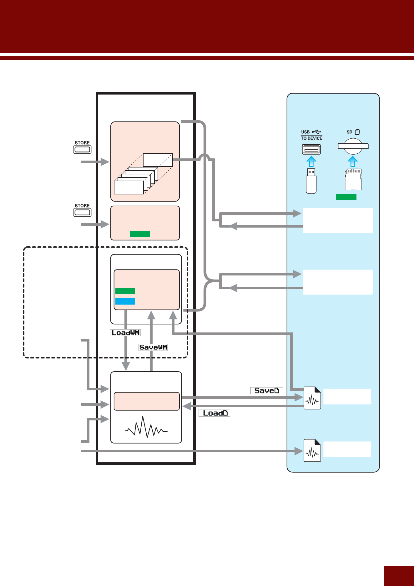
EAD50 EAD20 User Guide
33
Internal Memory Structure
U200
U001
U001
U001
U001
U001
U01–U50
U001–U100
U001–U500
U001–U200
EAD50
EAD20
Editing Scenes
(Page 90)
Editing Live Sets
(Page 185)
Sampling Function
(Page 180)
Recording by
Sampling
(Page 180)
Recording with
Looper
(Page 174)
Recording with
Recorder
(Page 164)
Samples
Live Set
Scene
Internal Memory
(IntMem)
Wave Memory
User Voices
[MIC/TRIG]
→
[F3] Setting
→
Kit
→
User Voice
→
Import Wave
Scene.bin
(Default File Name)
All.bin
External Memory
(Media)
XXXX.wav
XXXX.wav
[MENU]
→
File
→
File Scene
→
Save
[MENU]
→
File
→
File All
→
Load
[MENU]
→
File
→
File All
→
Save
[MENU]
→
File
→
File Scene
→
Load
Inside this unit
(
EAD50
only)
NOTE
For an explanation of interactions (save/import operations) between internal and external memory (media) for this
product, refer to Page 205.
EAD50
Only
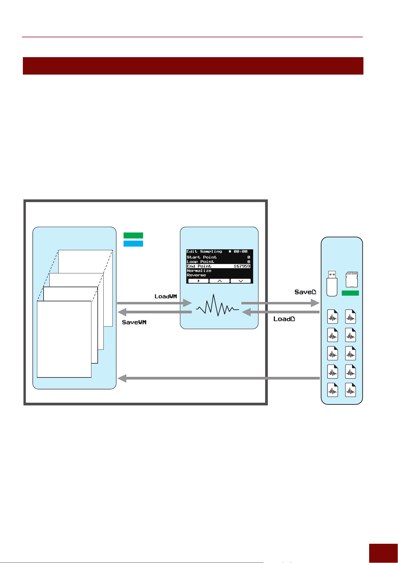
EAD50 EAD20 User Guide
34
Internal Memory Structure
Details of User Voice
• This product includes a region of memory, referred to as the “wave memory,” where recorded or imported waveform samples
are saved as User Voices.
• Each User Voice is composed of 10 banks. However, multiple banks cannot be sounded with the same Voice at the same
time. Adjust the velocity range and then play the Voice separately based on the hitting force level. If two banks share the
same velocity range, then the Voice is sounded for the bank with the lower bank number.
• Samples created by the Sampling function are assigned to one of those banks.
NOTICE
Only one sample can exist in internal memory at the same time.
When sound is recorded or an audio file is loaded, the data
that originally existed is deleted by overwriting. For data to be
retained, be sure to save it in external memory.
Load the sample to
be edited from a User
Voice or bank.
Wave Memory Internal Memory
External
Memory
(media)
Inside this unit
User Voice U001
• Bank 01 (B01)
• Bank 02 (B02)
• Bank 03 (B03)
• Bank 04 (B04)
• Bank 05 (B05)
• Bank 06 (B06)
• Bank 07 (B07)
• Bank 08 (B08)
• Bank 09 (B09)
• Bank 10 (B10)
User Voice U002
User Voice U003
User Voice Uxxx*
• Bank 01 (B01)
• Bank 02 (B02)
Save the created
sample in a User
Voice or bank.
Load an audio file
and finish editing it as
a sample.
Save the created file
as an audio file.
[MIC/TRIG]
→
Kit
→
User Voice
→
Import Wave
Existing audio files can be imported as a User Voice or bank.
EAD50
Only
*
EAD50
: U500
EAD20
: U100
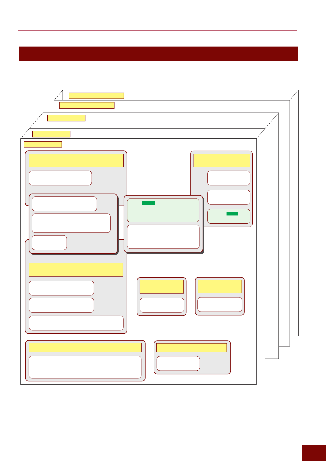
EAD50 EAD20 User Guide
35
Internal Memory Structure
Composition of Scenes
Scene 1 (P001)
Scene 2 (P002)
Scene xx (Pxxx)
User Scene 200 (U200)
User Scene 001 (U001)
Modifier
"
[SCENE]
"
[F1] ModSel
"
[+][−] button/knob
"
[SCENE]
"
[F3] Setting
"
Modifier
Effect
[MENU]
"
Effect
Mic/Kit Vol (Mic/Kit Volume)
[MIC/TRIG]
"
[F3] Setting
"
Mic
Trigger
[MIC/TRIG]
"
[F3] Setting
"
Trigger
Kit
[MIC/TRIG]
"
[F3] Setting
"
Kit
Function
[MIC/TRIG]
"
[F3] Setting
"
Kit
"
Voice
"
Voice Func
Settings for External Audio
Inputs
Utilities
[MENU]
"
Utility
Other Settings
(MIDI etc.)
Settings for Recording, Looping, and Sampling
Settings for External Audio Outputs
Settings Related to Mic Input Sounds (Sounds
from Hitting Acoustic Drums)
Settings for Electronic Drum Sounds Emitted
Based on Trigger Signals
Aux In
[MENU]
"
Aux In
Output
[MENU]
"
Output
Recorder
• [RECORDER]
"
Recorder
"
Select Audio File, [F3] Setting
• [RECORDER]
"
Looper
"
[F3] Setting
• [RECORDER]
"
Sampling
"
[F3] Setting
Mic
[MIC/TRIG]
"
[F3] Setting
"
Mic
USB Audio
[MENU]
"
USB Audio
Bluetooth (
EAD50
only)
[MENU]
"
Bluetooth
Click
[CLICK]
"
[F3] Setting
Settings for [CLICK]
Tempo
Enter settings on the screen displayed by
pressing [CLICK].
This tempo value is used for sequencer playback.
Click playback and Effects are also synchronized.
Fader (
EAD50
only)
• Fader mode selection status
• Fader function selection status
• [SCENE]
"
[F3] Setting
"
Fader
[SCENE] "[F3] Setting "Scene Load (Page 92)
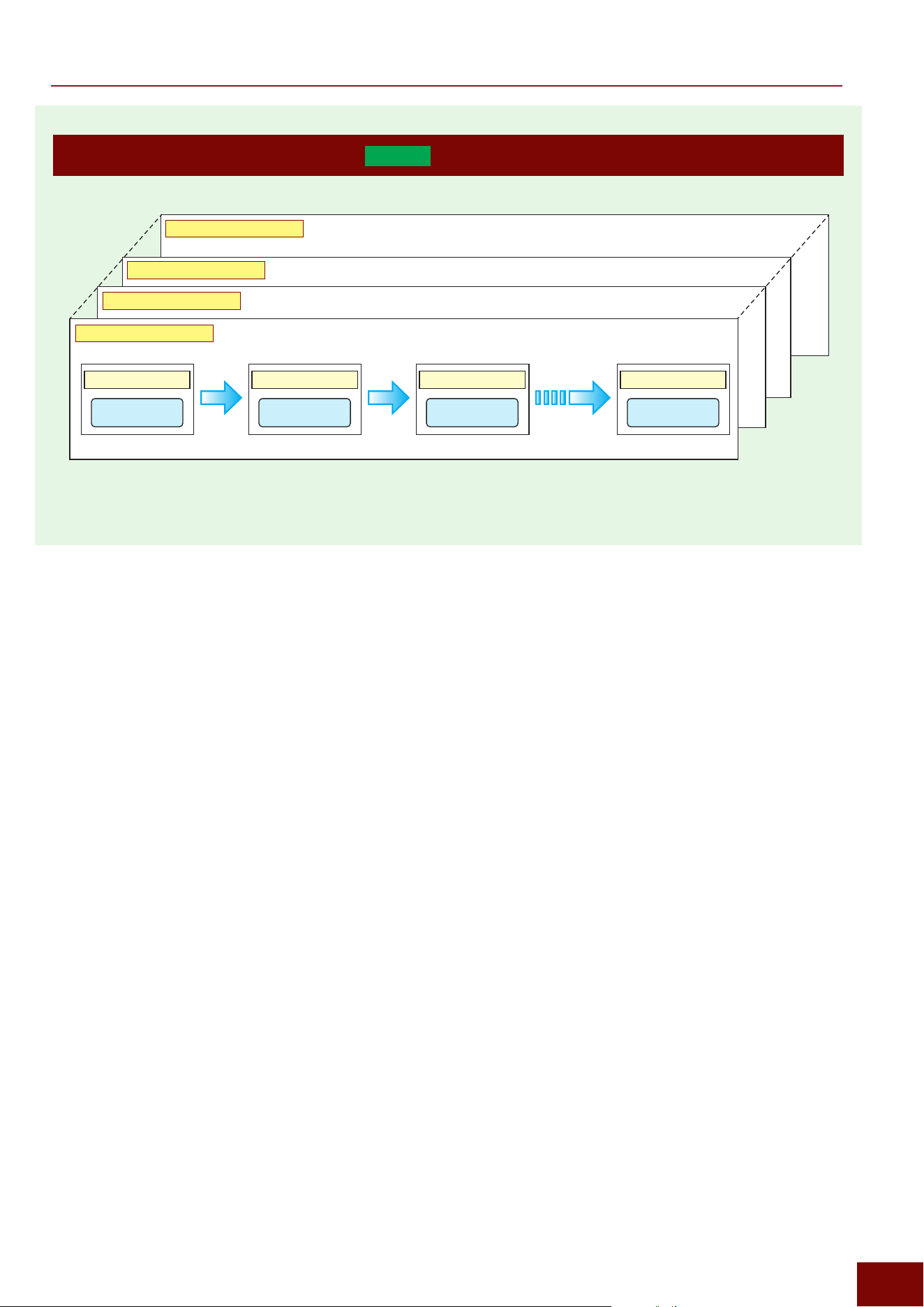
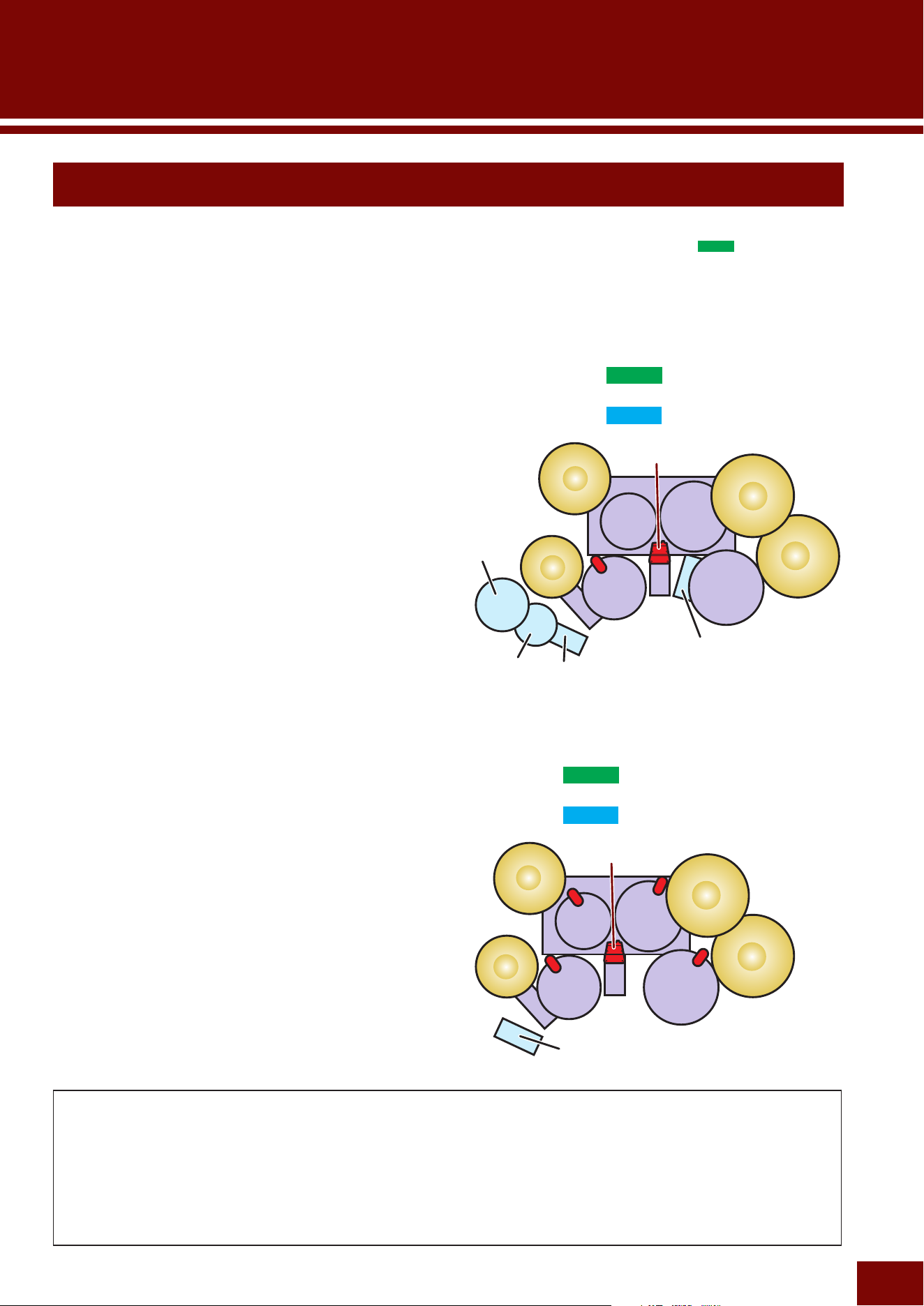
EAD50 EAD20 User Guide
37
Basic Setups
This product allows users to fully enjoy playing the drums by simply attaching the included Sensor Unit to the bass drum, but
richer drum performances can be achieved by also purchasing and attaching additional microphones (
EAD50
only), drum
Triggers, and/or electronic drum pads.
The following describes how to configure settings for Preset Scenes (Page 96) included in this product.
NOTE
For instructions on how to configure the system using this product alone (such as how to attach the Sensor Unit to the bass drum), refer
to the Quick Guide.
Preparation
Avoiding Interference between the Sensor Unit and Head
When setting up the drums, make sure there is no physical interference between the bass drum head and Sensor Unit. Be
especially careful about bass drums with a special construction around the outer perimeter of the bass drum. If there is any
interference, head vibration could cause problems with Sensor Unit microphone sounds or Trigger performance. In that
case, be sure to attach the Sensor Unit as far back as possible. If attached too close to the opening, it could cause not only
performance problems but also apply stresses to the hoop or cause the Sensor Unit to fall off. Be sure to attach the Sensor
Unit inside as far back as possible, as described in the DSU50 Owner's Manual (for EAD50) or Quick Guide. Then also
check for any interference.
■ Setup A
This setup involves connecting additional electronic drum
pads (sold separately) or Trigger sensors (sold separately)
that are not included with the acoustic drums. The setup
could be considered a basic configuration for a hybrid
drum set that can be played with a good balance between
acoustic and electronic drums. It also serves as the basic
configuration for Setup B and other setups.
■ Setup B
This setup consists of Setup A with Trigger sensors attached
to the tom drums (acoustic).
Mic1-Mic2, Kick
TO SENSOR UNIT
A (Kick), B (Mic)
Foot1
(HH65)
Trig5
(XP80)
Trig3
(KU100)
Snare
(DT50S)
Trig4
(PCY100)
EAD50
EAD20
Foot1
(HH65)
Trig5
(DT50S)
Snare
(DT50S)
Trig3
(DT50S)
Trig4
(DT50S)
Mic1-Mic2, Kick
TO SENSOR UNIT
A (Kick), B (Mic)
EAD50
EAD20
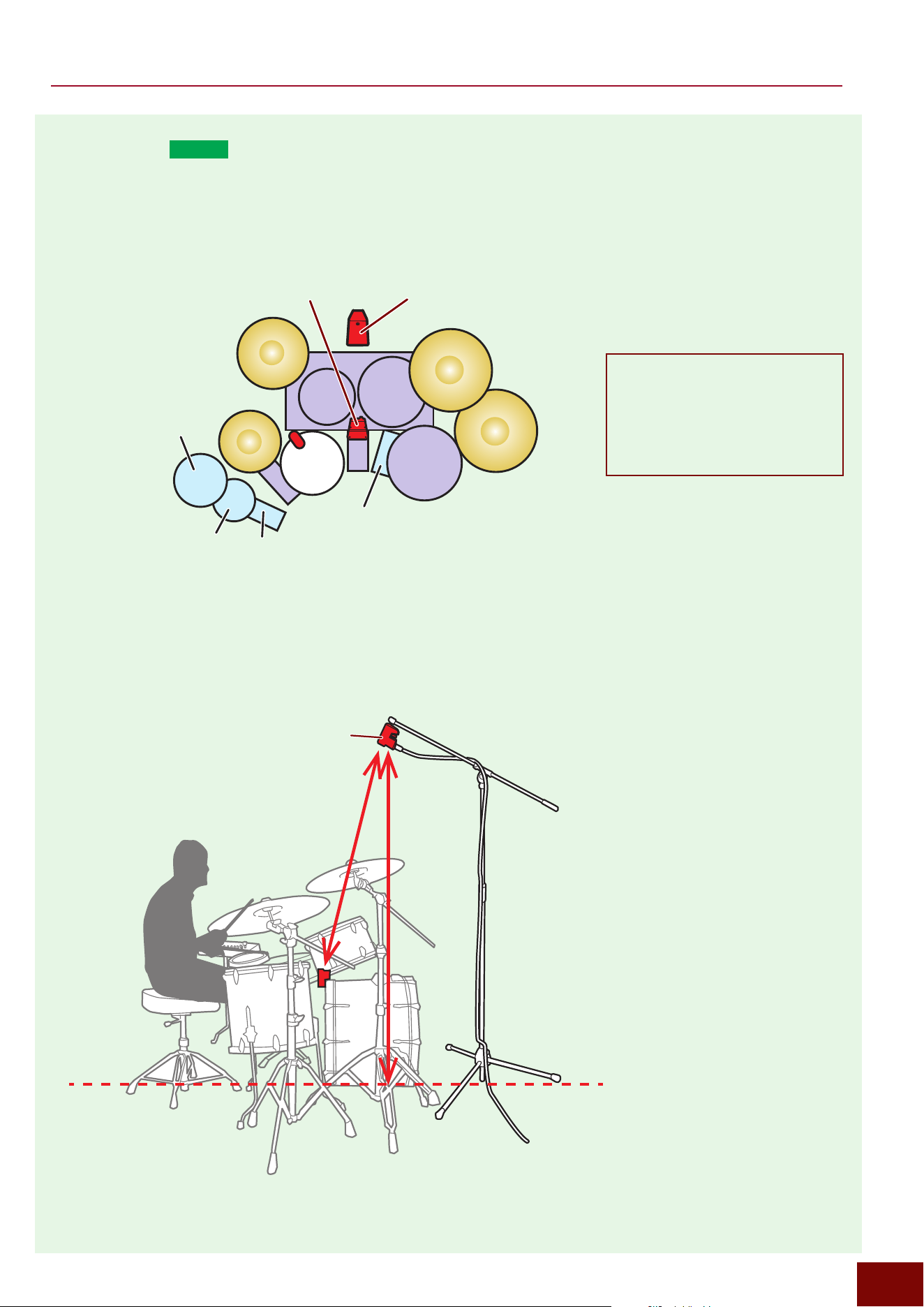
EAD50 EAD20 User Guide
38
Preparation
■ Setup C (
EAD50
only)
This setup consists of Setup A with an additional DSU50 unit (not included with the basic configuration) attached above the
player’s head. The additional DSU50 unit is generally oriented at the angle shown below, with respect to the hitting surface.
Top View
Side View
Foot1
(HH65)
Trig5
(XP80)
Trig3
(KU100)
Snare
(DT50S)
Trig4
(PCY100)
Mic1-Mic2, Kick
(DSU50)
Mic4-Mic3*
(DSU50)
120
180
Mic4-Mic3*
(DSU50)
Units: cm
* For DSU50 sensor units positioned
overhead and toward the front,
connect the L-connector (white) to
the [MIC 4] jack and the R-connector
(red) to the [MIC 3] jack. Otherwise,
the microphone left-right stereo
orientation with respect to the player
will be reversed.
NOTE
Adjust the angle and height as appropriate
for the performance venue environment or
preferred sound. If it is difficult to achieve
the desired angle or height, a ball joint-
type adapter can be connected between
the screws in the mic stand and the screw
holes in the mic (or DSU50 sensor).
NOTE
For instructions on how to use the Sensor
Unit attached to a mic stand, refer to the
DSU50 Owner's Manual.
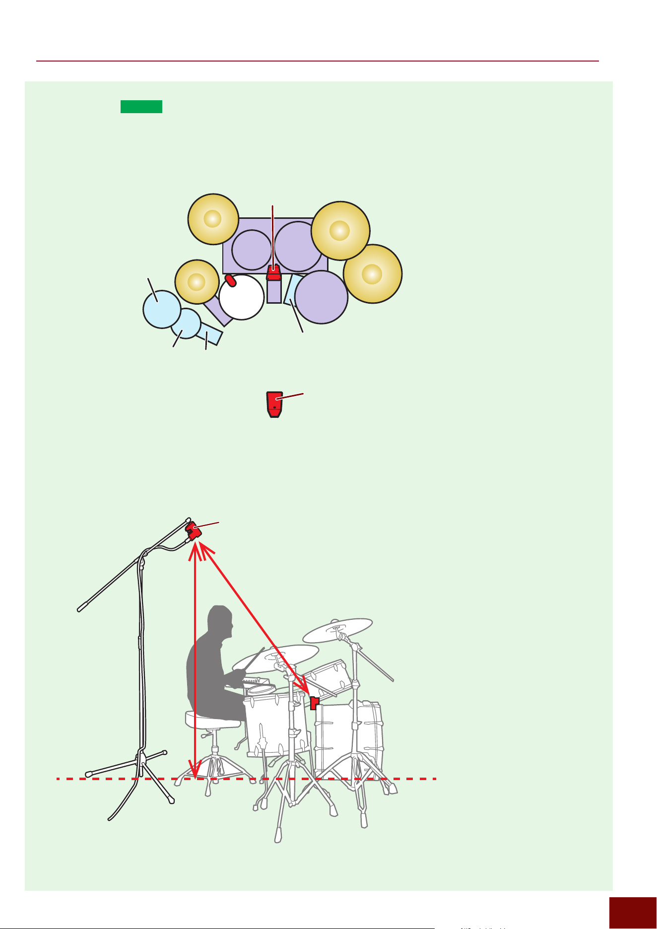
EAD50 EAD20 User Guide
39
Preparation
■ Setup D (
EAD50
only)
This setup consists of Setup A with an additional DSU50 unit (not included with the basic configuration) attached behind the
player. The additional DSU50 unit is generally oriented at the angle shown below, with respect to the hitting surface.
Top View
Foot1
(HH65)
Trig5
(XP80)
Trig3
(KU100)
Snare
(DT50S)
Trig4
(PCY100)
Mic3-Mic4
(DSU50)
Mic1-Mic2, Kick
(DSU50)
Side View
Units: cm
170
180
Mic3-Mic4
(DSU50)
NOTE
Adjust the angle and height as appropriate
for the performance venue environment or
preferred sound. If it is difficult to achieve
the desired angle or height, a ball joint-
type adapter can be connected between
the screws in the mic stand and the screw
holes in the mic (or DSU50 sensor).
NOTE
For instructions on how to use the Sensor
Unit attached to a mic stand, refer to the
DSU50 Owner's Manual.
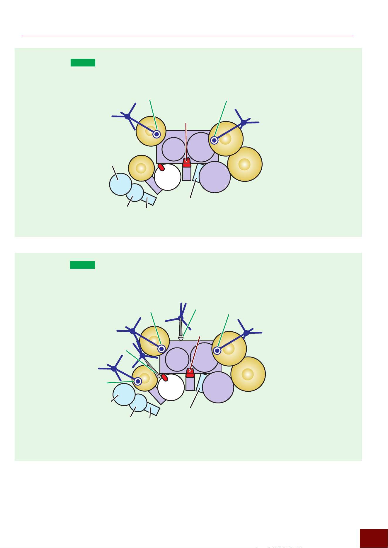
EAD50 EAD20 User Guide
40
Preparation
■ Setup E (
EAD50
only)
This setup consists of Setup A with an additional two microphones attached above and forward of the player’s head.
■ Setup F (
EAD50
only)
This setup is for configurations with a mic positioned for each instrument.
Foot1
(HH65)
Trig5
(XP80)
Trig3
(KU100)
Snare
(DT50S)
Trig4
(PCY100)
Mic L
<Mic3>
Mic R
<Mic4>
Mic1-Mic2, Kick
(DSU50)
Foot1
(HH65)
Trig5
(XP80)
Trig3
(KU100)
Snare
(DT50S)
HH
<Mic5>
Kick
(DSU50)
OH L
<Mic1>
OH R
<Mic2>
Trig4
(PCY100)
Kick
<Mic3>
Snare
<Mic4>

EAD50 EAD20 User Guide
41
Preparation
Connections to External Devices—Inputs
■ Mic Inputs and Line Inputs (
EAD50
only)
This product includes five [MIC/LINE INPUT] jacks on the rear panel for inputting sounds from acoustic drum performances
and from players speaking (talk). These connectors also can be used as line inputs for electronic musical instruments, guitar
amps, and other instrument audio inputs.
Five [MIC/LINE INPUT] jacks are used to input audio
sounds from performances into this product.
The volume levels of audio
input sounds are adjusted here.
Jacks 1 and 2, and 3 and 4, are paired as stereo inputs,
which can be specified on the screen below.
[MIC/TRIG]
"
[F3] Setting
"
Mic
"
Mic Pairing
NOTE
If using a DSU50 model, be sure to connect
it using the included cable. Using a
similarly-shaped lighting control cable (DMX
cable) can cause noise.
Precautions for Using the [MIC/LINE INPUT] Jacks
These [MIC/LINE INPUT] jacks are compatible with both TRS and XLR-type balanced phone plug connections. These two
types are selected based on the output level of the external device to be connected.
XLR Connectors
Used to connect devices with a low output level (devices that require gain amplification by this product). They are intended
for connecting mics for acoustic drum performances.
TRS Phone Jacks
Used to connect devices with a high output level. They are intended for connecting audio devices, electronic musical
instruments, and so on.
NOTE
In addition to selecting an XLR connector or a TRS phone jack, also be sure to adjust the output level appropriately on connected
input devices.
■ Trigger Inputs
Refer to Pages 24 and 25.
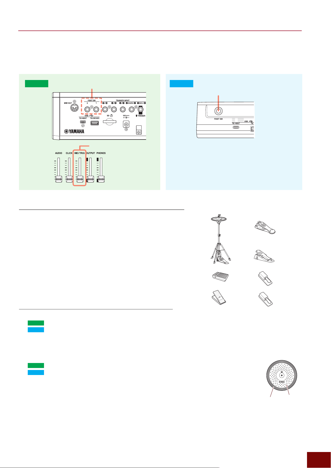
EAD50 EAD20 User Guide
42
Preparation
■ Inputs from a Foot Switch/Foot Controller
Connecting a pedal to the [FOOT SW] jack allows the following three types of functions to be used, including producing Trigger
sounds.
Adjust the Trigger volume level here.
[FOOT SW 1, 2] Jacks
[FOOT SW] Jack
EAD50
EAD20
Use the following screen to set the volume of tone
generator sounds produced according to input MIDI
messages.
[MENU]
"
Utility
"
Mic/Trigger Volume
Functionality Assignable to a Foot Switch/Foot Controller
z
Functionality for Generating Trigger Sounds
[MIC/TRIG]
"
[F3] Setting
"
Kit
"
Inst
"
Inst
"
Category, Number
[MIC/TRIG]
"
[F3] Setting
"
Kit
"
Voice
"
Voice
"
Category, Number
z
Functionality for Switching
This includes switching Scenes, switching Live Sets, setting Talk settings,
and switching Xstick on/off.
[MIC/TRIG]
"
[F3] Setting
"
Kit
"
Voice
"
Voice Func
z
Functionality for Adjusting
Controlling tempo, volume, modifier, and other levels.
[MIC/TRIG]
"
[F3] Setting
"
Kit
"
Voice
"
Voice Func
Settings for Foot Switch/Foot Controller Connections
z
Specifying the Model to Be Connected to the Jack
EAD50
[MIC/TRIG]
"
[F3] Setting
"
Trigger
"
Trig In
"
Foot Sw1, Foot Sw2
"
Type
EAD20
[MIC/TRIG]
"
[F3] Setting
"
Trigger
"
Trig In
"
Foot Sw
"
Type
z
Setting for Use as a Hi-Hat Controller
If a setting other than “HH Trig In = Off” is specified on the screen below, then the specified Trigger Input
is treated as hi-hat cymbal sounds. That allows 6 types of cymbal sounds to be controlled by playing
techniques, including using a pedal.
EAD50
[MIC/TRIG]
"
[F3] Setting
"
Trigger
"
Foot Sw1, Foot Sw2
"
HH Trig In
EAD20
[MIC/TRIG]
"
[F3] Setting
"
Trigger
"
Foot Sw
"
HH Trig In
- OpBw: Sound produced when the bow area of the cymbal pad is hit with the pedal not pressed or lightly pressed.
- OpEg: Sound produced when the edge of the cymbal pad is hit with the pedal not pressed or lightly pressed.
- ClBw: Sound produced when the bow area of the cymbal pad is hit with the pedal pressed.
- ClEg: Sound produced when the edge area of the cymbal pad is hit with the pedal pressed.
- FtCl: Foot-closed sound produced by pressing the pedal.
- FtSp: Foot splash sound produced by pressing and then immediately releasing the pedal.
z
Assigning Functions Other Than for Generating Trigger Sounds to Trigger Input Sources
[MIC/TRIG]
"
[F3] Setting
"
Kit
"
Voice
"
Voice Func
FC3A
Pedal returns
when released
FC7
Pedal position
retained when
released
FC4A
FC5
HH65
RHH135
(+Hi-Hat Stand))
HH40
Edge area
Bow area
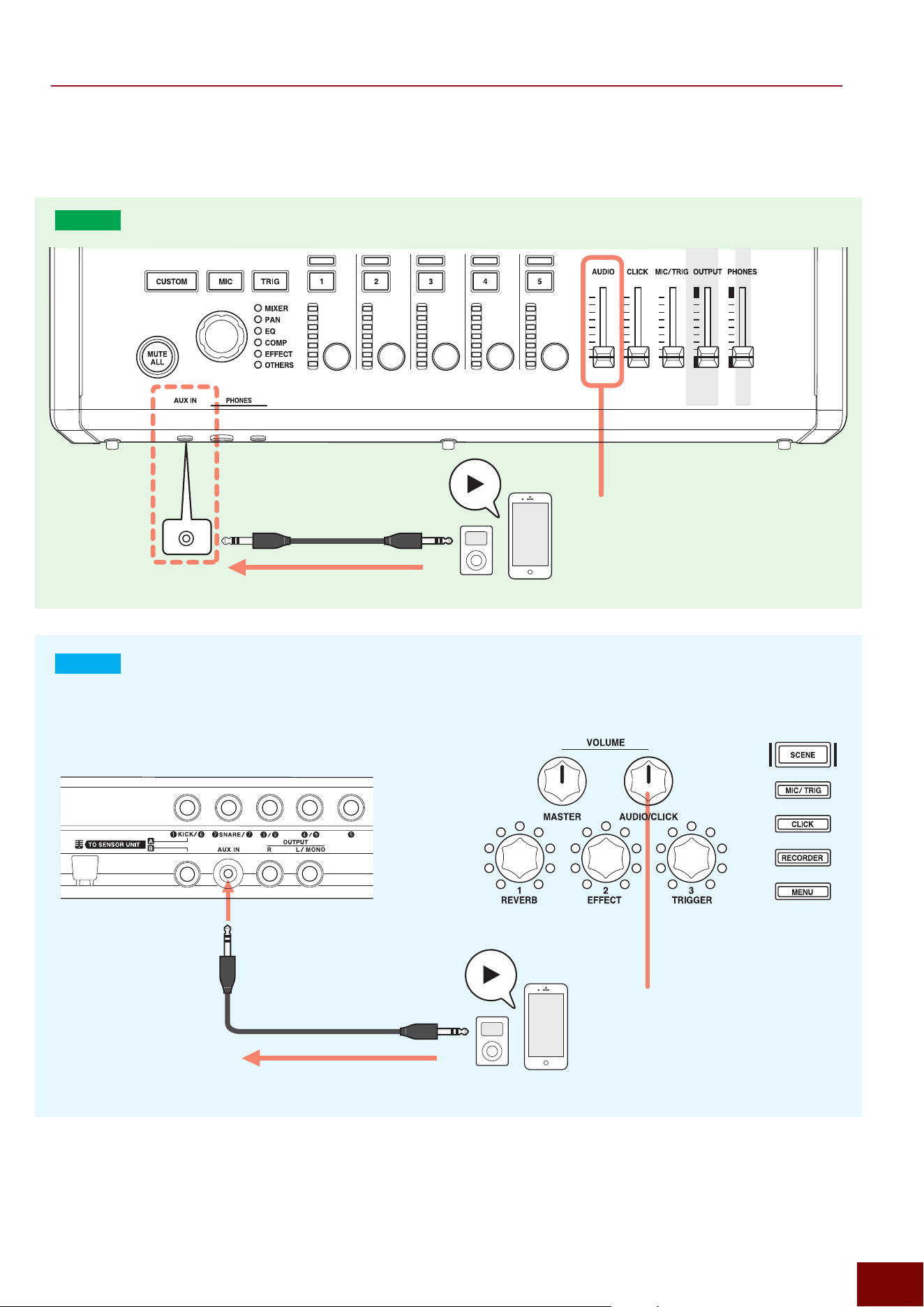
EAD50 EAD20 User Guide
43
Preparation
■ AUX IN
This product lets you hear playback sounds from external audio devices.
EAD50
EAD20
1
2
Adjust the input volume level here.
Rear Panel Top Panel
1
2
Adjust the input volume level here.
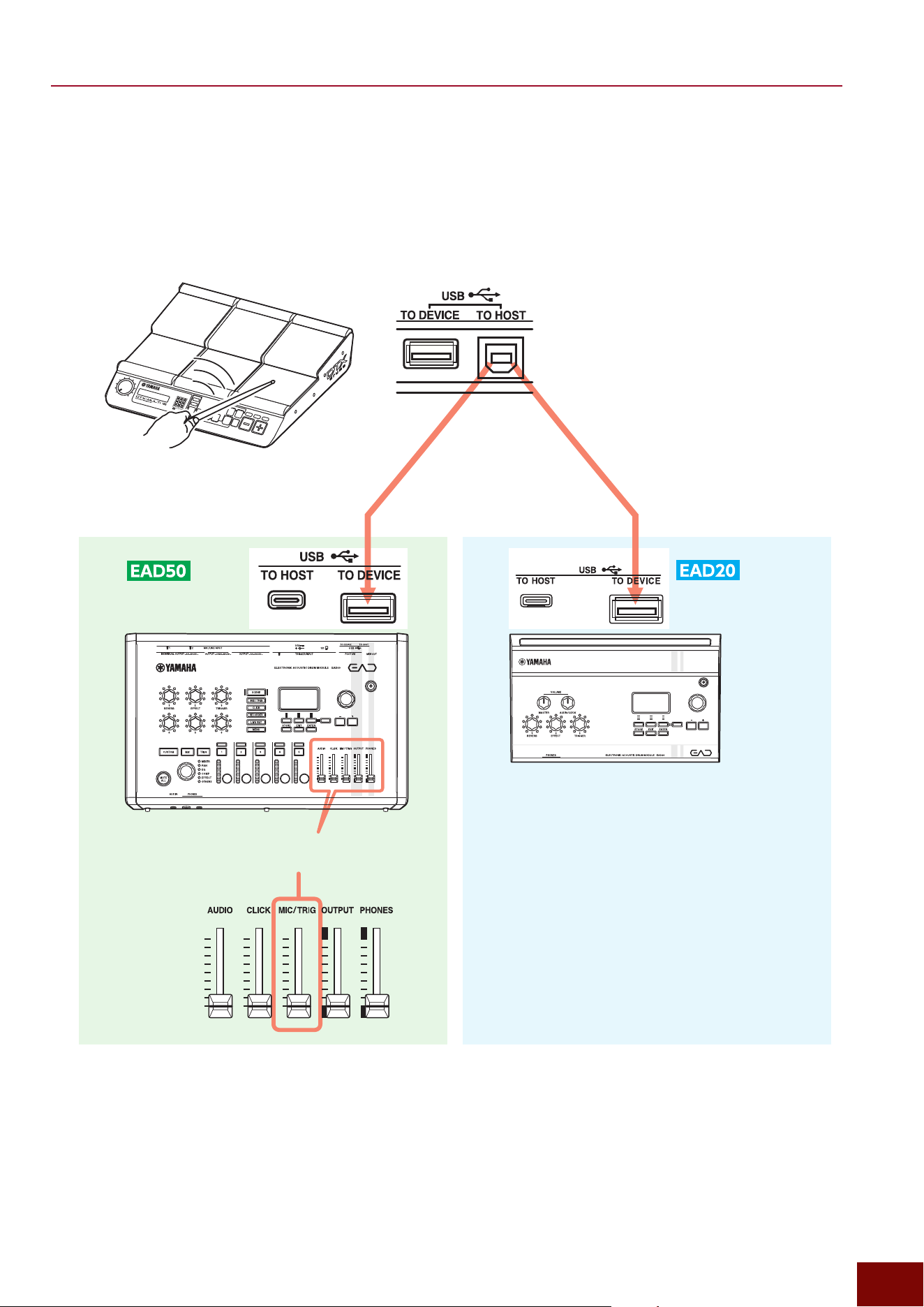
Adjust the volume of tone generator sounds
produced in response to MIDI messages inputs.
Use the following screen to set the volume of tone
generator sounds produced according to input MIDI
messages.
[MENU]
"
Utility
"
Mic/Trigger Volume
EAD50 EAD20 User Guide
44
Preparation
■ Using USB Cables for MIDI Inputs (USB TO DEVICE)
This product is equipped with the USB Trigger Link function. This lets you receive MIDI messages via a USB cable to play the
performance of other MIDI device with the tone generator block of this product.
MIDI device
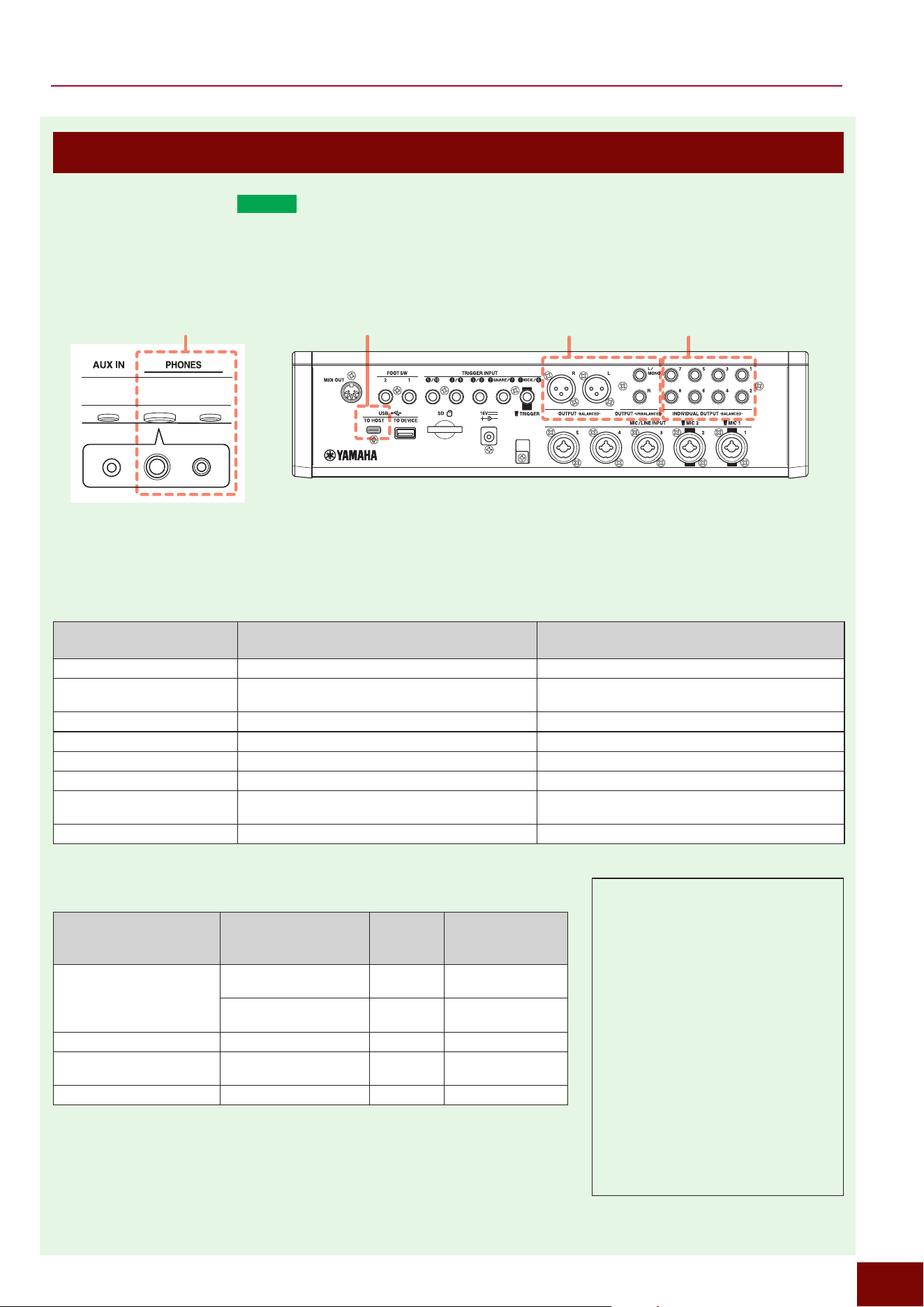
EAD50 EAD20 User Guide
45
Preparation
Connections to External Devices—Outputs
■ Audio Outputs (
EAD50
)
The various sounds input to this product can be output by several methods, as shown below, with settings configured
separately for each channel.
NOTE
The following screen can be used to adjust the output
gain for individual jacks.
[MENU]
"
Output
"
Output Gain
Phones Out USB Audio Out Main Out IndivOut
NOTE
Using both jacks simultaneously
will decrease the output volume
to the headphones.
Front Panel Rear Panel
Input Sound
(Audio Channel)
Screen for Setting the Output Destination
Output Destination Device for Setting Output
or No Output
Sound input from each mic jack [MIC/TRIG]
"
[F3] Setting
"
Mic
"
Mic Out Main Out*, Phones Out*, USB Audio Out 1/2*, IndivOut
Each Inst sounded based on signal
input from Trigger jack
[MIC/TRIG]
"
[F3] Setting
"
Kit
"
Inst
"
Inst Out
Main Out**, Phones Out**, USB Audio Out 1/2**, IndivOut
Click sound [CLICK]
"
[F3] Setting
"
Click Out Main Out, Phones Out, USB Audio Out 1/2, IndivOut
Recorder playback sound [RECORDER] (Recorder)
"
[F3] Setting
"
Recorder Out Main Out, Phones Out, USB Audio Out 1/2, IndivOut
Looper playback sound [RECORDER] (Looper)
"
[F3] Setting
"
Looper Out Main Out, Phones Out, USB Audio Out 1/2, IndivOut
Sound input via [AUX IN] jack [MENU]
"
Aux In
"
Aux In Out Main Out, Phones Out, USB Audio Out 1/2, IndivOut
Sound input via [USB TO HOST]
terminal
[MENU]
"
USB Audio
"
USB AudioOut Main Out, Phones Out, USB Audio Out 1/2, IndivOut
Sound input via Bluetooth [MENU]
"
Bluetooth
"
BluetoothOut Main Out, Phones Out, USB Audio Out 1/2, IndivOut
* Only enabled if [MIC/TRIG]
"
[F3] Setting
"
Mic
"
Mic Out
"
Effect Thru = On
** Only enabled if [MIC/TRIG]
"
[F3] Setting
"
Kit
"
Inst
"
Inst Out
"
Effect Thru = On
Audio Outputs
(On-screen indication)
Corresponding Connector
Volume
Adjustment
Slider
Connected Device
Main Out
OUTPUT -BALANCED- OUTPUT
Amp, speaker, or other
PA device
OUTPUT -UNBALANCED- OUTPUT
Amp, speaker, or other
PA device
Phones Out
PHONES PHONES Headphones
USB Audio Out USB TO HOST OUTPUT
Computers, smart
devices, etc.
IndivOut INDIVIDUAL -BALANCED- - Mixer or other PA device
Balanced vs Unbalanced
This product includes input/output
jacks that support both balanced and
unbalanced signals. In particular,
it is equipped with both types of
[OUTPUT] jacks, which should be
selected based on the following
criteria.
• Balanced jacks are more tolerant of
noise, making them more suitable
for microphones with low input/
output level and longer cables.
• Unbalanced jacks are mainly used
to connect line devices (synthesizers
and other electronic musical
instruments or acoustic devices) or
small acoustic devices.
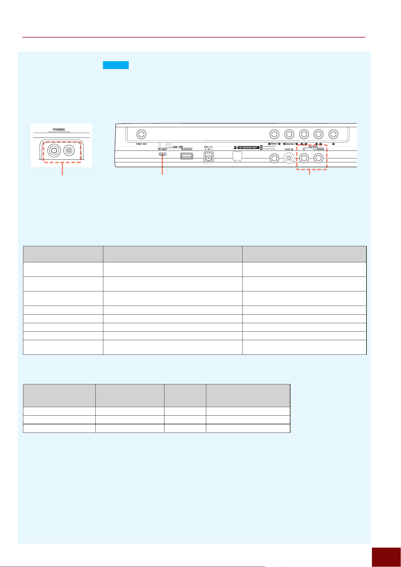
EAD50 EAD20 User Guide
46
Preparation
■ Audio Outputs (
EAD20
)
The various sounds input to this product can be output by several methods, as shown below, with settings configured
separately for each channel.
NOTE
The following screen can be used to adjust the output
gain for individual jacks.
[MENU]
"
Output
"
Output Gain
Phones Out
USB Audio Out Main Out
NOTE
Using both jacks simultaneously
will decrease the output volume
to the headphones.
Front Panel Rear Panel
Input Sound
(Audio Channel)
Screen for Setting the Output Destination
Output Destination Device for Setting Output
or No Output
Sound input from each mic jack [MIC/TRIG]
"
[F3] Setting
"
Mic
"
Mic Out Main Out*, Phones Out*, USB Audio Out 1/2*,
USB AudOut*
Each Inst sounded based on signal
input from Trigger jack
[MIC/TRIG]
"
[F3] Setting
"
Kit
"
Inst
"
Inst Out Main Out**, Phones Out**, USB Audio Out 1/2**, USB
AudOut**
Performance sound after processing
with system and Master Effects
[MIC/TRIG]
"
[F3] Setting
"
Effect
"
Effect Out Main Out, Phones Out, and USB Audio Out 1/2
Click sound [CLICK]
"
[F3] Setting
"
Click Out Main Out, Phones Out, and USB Audio Out 1/2
Recorder playback sound [RECORDER] (Recorder)
"
[F3] Setting
"
Recorder Out Main Out, Phones Out, and USB Audio Out 1/2
Looper playback sound [RECORDER] (Looper)
"
[F3] Setting
"
Looper Out Main Out, Phones Out, and USB Audio Out 1/2
Sound input via [AUX IN] jack [MENU]
"
Aux In
"
Aux In Out Main Out, Phones Out, and USB Audio Out 1/2
Sound input via [USB TO HOST]
terminal
[MENU]
"
USB Audio
"
USB AudioOut Main Out, Phones Out, and USB Audio Out 1/2
* Only enabled if [MIC/TRIG]
"
[F3] Setting
"
Mic
"
Mic Out
"
Effect Thru = On
** Only enabled if [MIC/TRIG]
"
[F3] Setting
"
Kit
"
Inst
"
Inst Out
"
Effect Thru = On
Audio Outputs
(On-screen indication)
Corresponding Connector
Volume
Adjustment
Knob
Connected Device
Main Out OUTPUT L/MONO R MASTER Amp, speaker, or other PA device
Phones Out
PHONES MASTER Headphones
USB Audio Out USB TO HOST AUDIO/CLICK Computers, smart devices, etc.
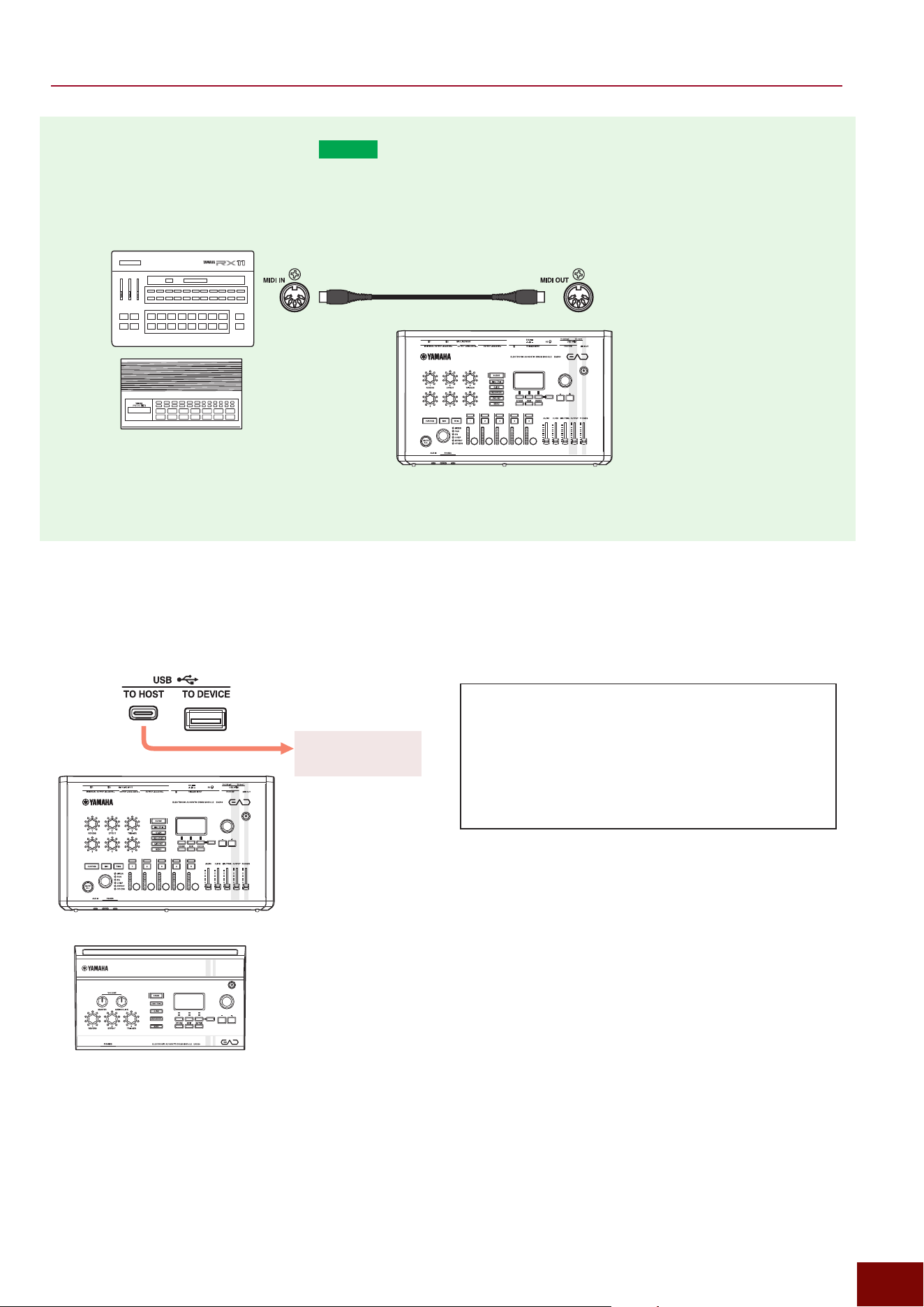
EAD50 EAD20 User Guide
47
Preparation
■ Outputs via MIDI Cable (
EAD50
only)
When playing performances based on Trigger signals, this product can play not only Voices assigned to this product but also
Voices output from an external MIDI device by sending MIDI messages.
[MIC/TRIG]
"
[F3] Setting
"
Kit
"
Voice
"
Voice MIDI
■ MIDI Outputs to External MIDI Devices via USB (USB TO HOST)
If a MIDI device with USB Trigger Link function is connected to the [USB TO HOST] terminal on this product, sound can be
produced from the connected MIDI device based on MIDI messages generated by performances using this product.
This can be used to connect
Yamaha RX11, RX21, and
other vintage rhythm machine
models from an era without
USB connectors.
EAD unit
NOTE
The [MIDI OUT] terminal only
supports MIDI messages from
Port 1. Note that Port 2 MIDI
messages are not output.
EAD unit
MIDI device with USB
Trigger Link function
Optimizing Sound from Connected MIDI Devices
Voices from connected MIDI devices can be optimized
by using the following screen to specify note numbers
and channels for each Trigger Input Source layer.
[MIC/TRIG]
"
[F3] Setting
"
Kit
"
Voice
"
Voice MIDI
Configure settings by referring to the note map for the
MIDI device.
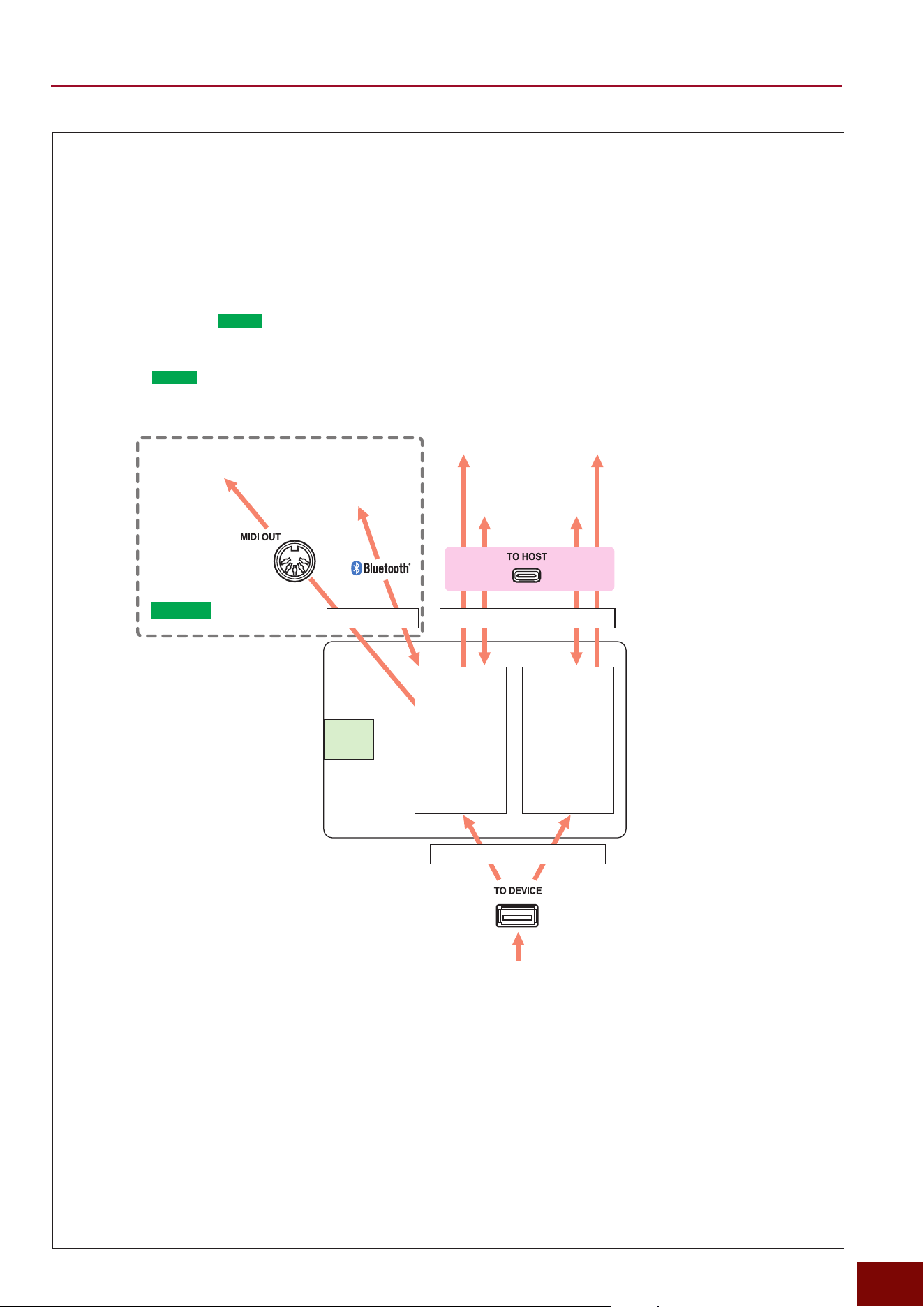
EAD50 EAD20 User Guide
48
Preparation
MIDI Specifications
This product can send/receive a total of 32 channels (16 channels × 2 ports) of MIDI messages by the following methods.
• [USB TO HOST] terminal
Communication (send/receive) with apps by connecting to a computer or smart device. MIDI transmission is also
possible to other devices with the same USB Trigger Link function as this product.
• [USB TO DEVICE] terminal
The USB Trigger Link function can be used to receive MIDI transmissions from other drum Trigger modules (electronic
musical instruments) with USB-MIDI function.
• [MIDI OUT] terminal (
EAD50
only)
MIDI transmissions can only be sent to Port 1 on other MIDI devices (drum Trigger modules) equipped with a MIDI input
terminal. (Page 47)
• Bluetooth (
EAD50
only)
Enables MIDI communication (send/receive) with external Bluetooth devices.
Port 1
1 ch
2 ch
3 ch
4 ch
5 ch
:
:
:
16 ch
Port 2
1 ch
2 ch
3 ch
4 ch
5 ch
:
:
:
16 ch
Computer, smart
device, etc.
MIDI device with USB Trigger Link function
(Trigger module, etc.)
MIDI device
(Trigger module, etc.)
MIDI device
(Trigger module, etc.)
Bluetooth devices,
such as smart devices.
Channel settings Port and channel settings
Port and channel settings
EAD
unit
EAD50
only
Related Settings
• Port
[MIC/TRIG]
"
[F3] Setting
"
Kit
"
Voice
"
Voice MIDI
"
Note Port
• Sending Channel
[MIC/TRIG]
"
[F3] Setting
"
Kit
"
Voice
"
Voice MIDI
"
Ch (Notes 1
to
4)
• Receiving Channel
[MIC/TRIG]
"
[F3] Setting
"
Kit
"
Voice
"
Voice MIDI
"
Note1 Ch
NOTE
For more detailed specifications, refer to the MIDI document located in the separate “Data List” file (Page 4).
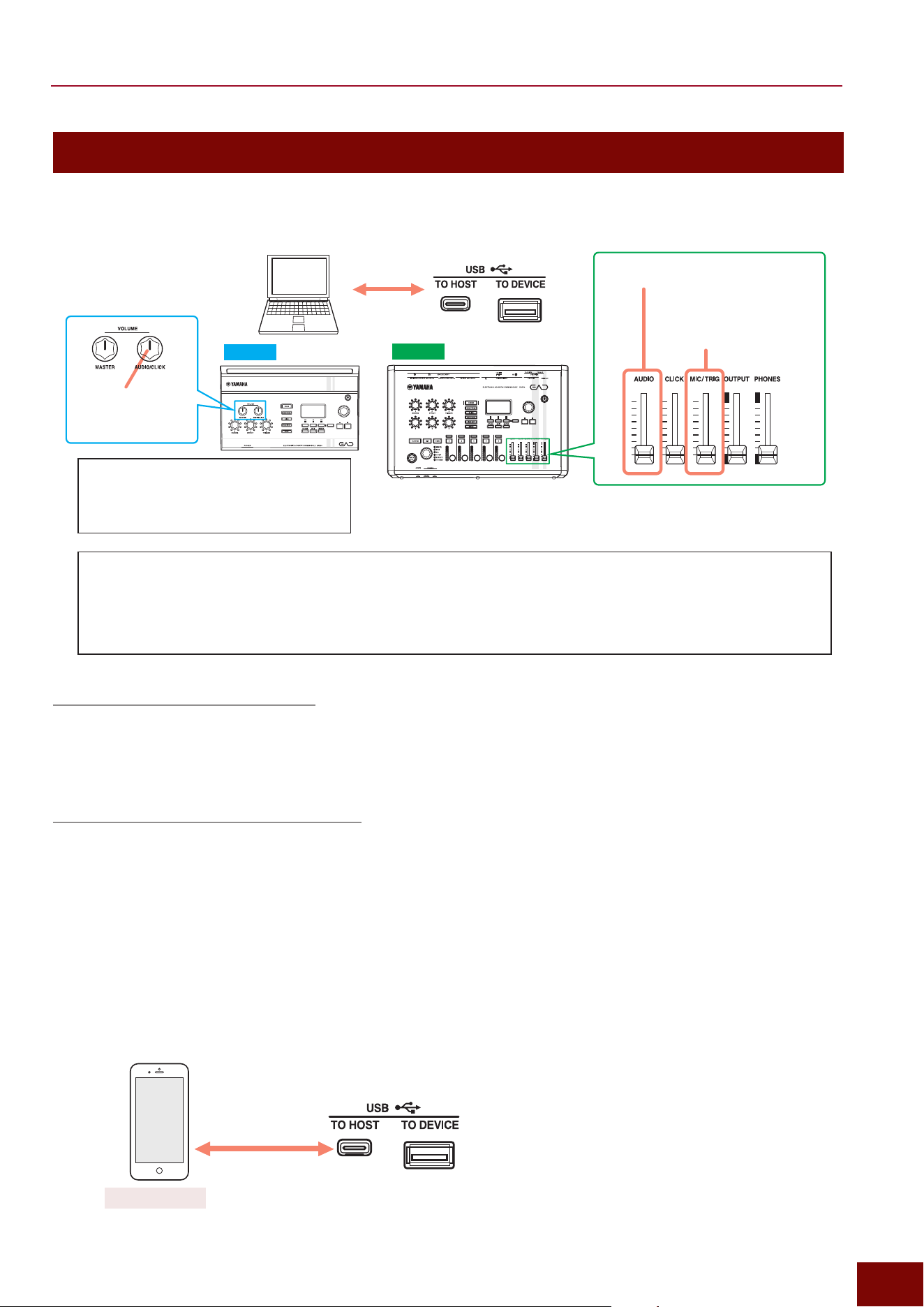
EAD50 EAD20 User Guide
49
Preparation
Connections to External Devices— I/O
■ MIDI/Audio Communication with a Computer (USB TO HOST)
Connection to a Computer (Mac)
1. Prepare a USB cable appropriate for the type of computer connector.
2. Connect the USB cable to this product before connecting the other end to the computer. A driver does not need to be
installed.
Connection to a Computer (Windows)
1. Download the Yamaha Steinberg USB Driver from the Yamaha website (https://download.yamaha.com/).
2. Install the Yamaha Steinberg USB Driver in the computer.
3. Prepare a USB cable appropriate for the type of computer connector.
4. Connect the USB cable to this product before connecting the other end to the computer.
■ MIDI/Audio Communication with a Smart Device (USB TO HOST)
Performances using this product (audio) can be recorded using a smart device app. Prepare and connect a USB cable
appropriate for the connector shape in the smart device.
Adjusts the volume of the
sound produced by MIDI
messages from a computer.
Adjusts the volume of audio from
a computer
DAW
EAD50
EAD20
Adjusts the volume
of audio from a
computer
Switching between USB Audio Communication Specifications
This product can use either of the following types of USB audio communication: 2 in/2 out (24-bit, 44.1/48/96kHz
synchronized) or 8 in/10 out (24-bit, 44.1kHz asynchronous). The communication method used can be selected by
selecting the setting on the following screen and then turning the power off and on.
[MENU]
"
USB Audio
"
USB Audio
"
Mode
EAD50
Rec'n'Share
NOTE
For more information about connecting a smart
device to this product, refer to the following manuals
posted on the Yamaha website.
• Smart Device Connection Manual for Android
• Smart Device Connection Manual for iPhone/iPad
Use the following screen to set the volume of tone
generator sounds produced according to input MIDI
messages.
[MENU]
"
Utility
"
Mic/Trigger Volume
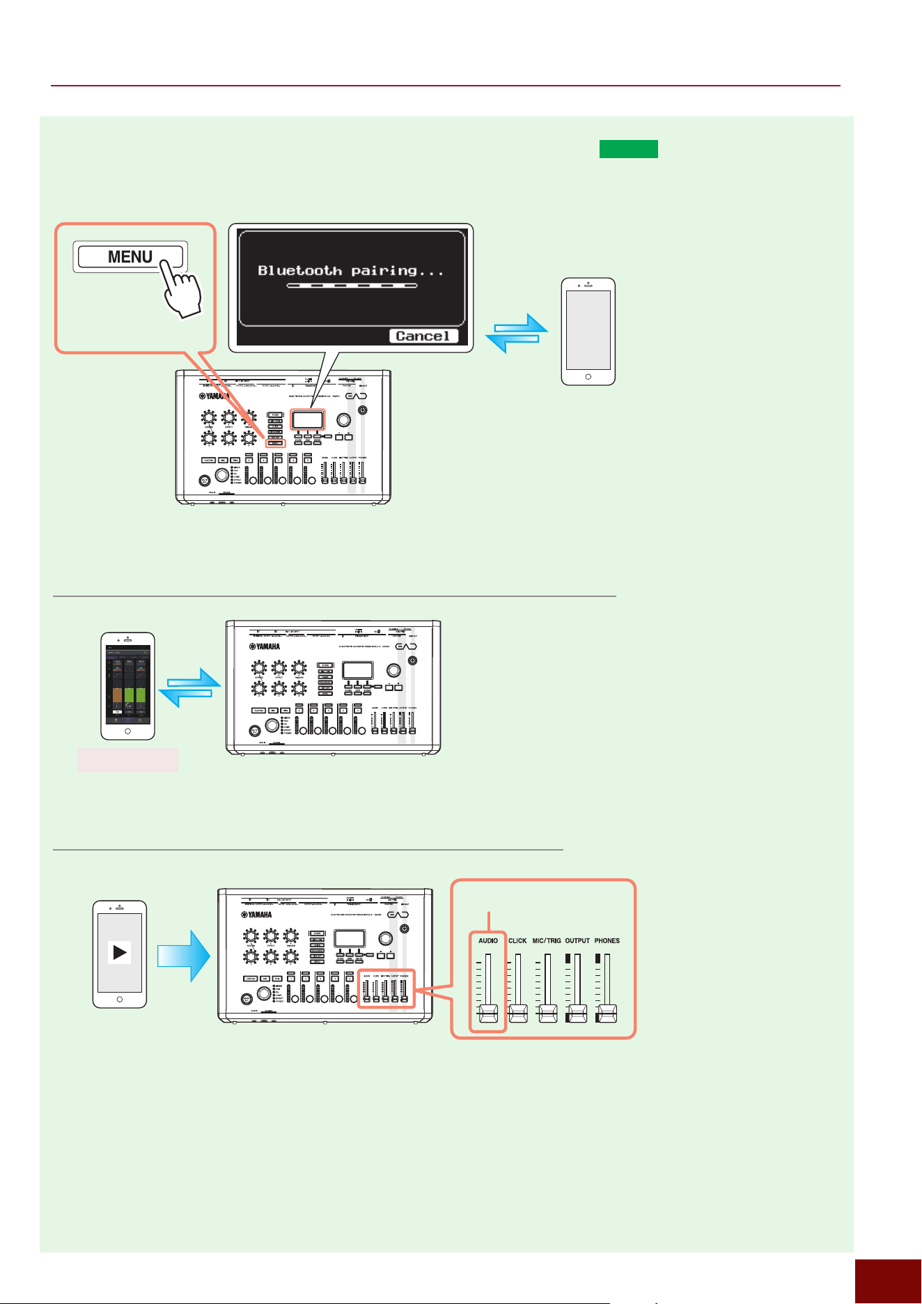
EAD50 EAD20 User Guide
50
Preparation
■ Wireless (Bluetooth) MIDI and Audio Communication (
EAD50
only)
This product includes Bluetooth functionality. By performing the following operations, this product can be wirelessly connected
to smart devices and other compatible devices for both MIDI and audio communications.
EAD unit
Bluetooth = On
Long
press
NOTE
For more detailed Bluetooth settings, refer to Page 200.
Using a Specialized App to Edit EAD Settings by MIDI Communication
Using this product to Playback Audio Data from a Smart Device
EAD unit
EAD Touch
EAD unit
Adjusts the audio playback volume
EAD50 EAD20 User Guide
51
Preparation
Bluetooth
(
EAD50
only)
Bluetooth
is technology that enables wireless communication between compatible devices using the 2.4 GHz electromagnetic
frequency band.
■ Using
Bluetooth
Communication
• The 2.4 GHz frequency band used by
Bluetooth
devices is also shared by a wide variety of other devices.
Bluetooth
-
compatible devices use technology for minimizing the effects from other devices that use the same frequency band.
Nevertheless, other devices using the same band can result in slower communication speeds, shorter communication
distances, or communication interruptions.
• Therefore, the communication speed and distance of devices can vary depending on the distance and obstructions between
communicating devices, the electromagnetic wave status, and the type of devices.
• This product does not guarantee connectivity with all devices compatible with
Bluetooth
functionality.
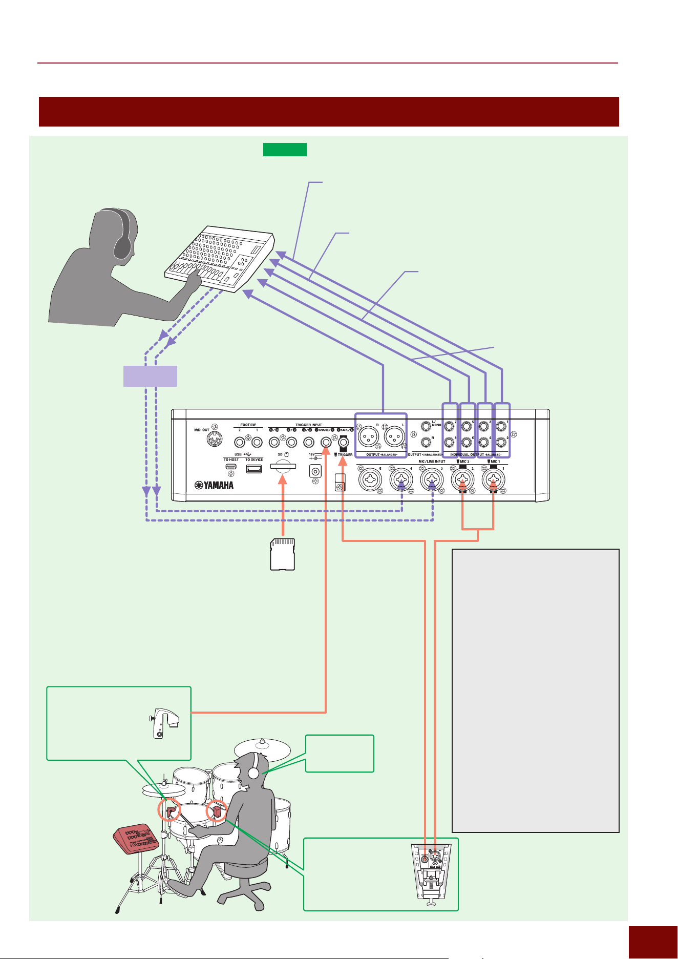
EAD50 EAD20 User Guide
52
Preparation
IndivOut=L1+R2
DSU50 sound (Mic1, 2) outputs without System Effects applied.
Mic Out
"
IndivOut = L1+R2
EQ Tran Thru = Off (Pag e 116)
FOH* Mixer
*
Abbreviation for “front of house”
that refers to the audience
space in a concert event hall.
Drum performances
(Trigger Signals)
input via provided
cables
EAD50
unit
Included DSU50
Sensor Unit
Trigger Signal acquired by
hitting bass drum
Monitor
Refer to the
next page.
Drum performances (audio)
input via provided cables
DT50S or other
Trigger Sensor
(sold separately)
Trigger Signal acquired
by hitting snare drum
Individual Outputs (IndivOut)
A major feature of this product is
the ability of the drummer to mix
the optimal sound themself using
the monitor sound as a reference.
On the other hand, for small live
performance venues, for example,
the sound balance experienced by
the audience (FOH) can be different
than the balance intended by the
drummer, due to sounds directly
from the drums and reverberation
effects of the facility. In such cases,
the INDIVIDUAL OUTPUT jacks
can be used to output drum, effect,
and Trigger sounds individually.
Then the optimal sound balance, as
experienced by the audience, can
be achieved by using the FOH mixer
to adjust the balance between the
respective sounds.
Of course, if there is no problem with
the sound settings configured by the
drummer, then the sound output from
Main Out can be output directly to the
speakers.
PA Monitors
Main Out
Drum performance sound.
PA Monitors
Vocal, guitar, or other
performance sounds routed
back to the drummer
headphones for monitoring
are input via Mic3 and
Mic4 jacks. The connection
example shown requires
the following settings.
• Mic3/4 =Paired (Page 108)
• Effect Thru = On (Page 116)
• Main Out = Off (Page 116)
• Phones Out = On (Pag e 116)
IndivOut=L3, R4
Return sound from System Effects (Reverb, FX1, or FX2)
Return IndivOut = L3+R4 (Pages 148 and 150)
IndivOut=L5, R6
Trigger sounds, such as from a DSU50 or DT50S unit,
without System Effects applied.
Inst Out
"
IndivOut = L5 (Kick)
Inst Out
"
IndivOut = R6 (Snare)
EQ Tran Thru = Off (Pages 132 and 133)
IndivOut=L7+R8
Sounds played from an SD card
Recorder Out
"
IndivOut = L7+R8
(Page 173)
Media
• Used to play backing or
Click sounds (Page 167)
• Click sounds cannot be
output via the Main Out
jacks and can only be
output to headphones
(Page 172).
Setting examples for Specific Use Cases
■ Setup for Live Performances
EAD50
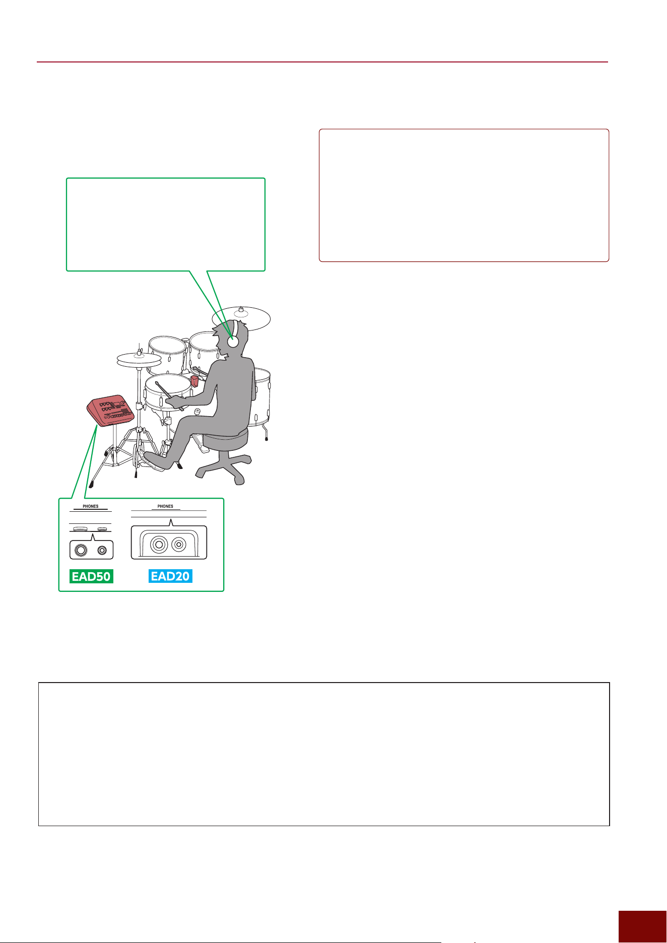
EAD50 EAD20 User Guide
53
Preparation
■ Setup (Around the Monitor) for Live Performances
Headphones/Earphones Selection
To achieve an appropriate monitor
sound, we recommend using an IEM
(in-ear monitor) device with high sound
insulation and configured to clearly
hear even low-volume sounds.
z
To play while hearing clicks
To prevent the audience from hearing Click sounds (so that they are
only audible via your own headphones), configure the settings as
follows. For more information, refer to Page 163.
[CLICK]
"
[F3] Setting
"
Click Out
• Phones Out=On
• Main Out=Off
• USB Audio Out 1/2=Off
• IndivOut=Off
z
If the volume seems too low
Adjust the volume on the following screen.
[MENU]
"
Output
"
Output Gain
"
Phones Out
z
Adding a stereo feel to the monitor sound
In live music venues, PA feedback (monitor) sounds are often
returned as monaural audio. When monitor sounds are combined
as monaural audio, multiple instruments can sound like they are in
a central position, which can make it feel hard to hear individual
instruments. In such situations, the Effect type that adds a stereo
sensation to monaural audio can be used to make it easier to monitor
sounds via headphones or earphones.
• Effect Block: Ins1 Mic or Ins2 Mic
• Effect Type: Mono In < Wide (category: Stereo)
Be Careful of the Howling When Setting Up Monitor Speakers!
If setting up monitor speakers, be especially careful of the monitor speaker orientation. If a significant amount of speaker
sound enters the sensor unit, it can cause howling (a phenomenon that generates a loud squeal sound due to a feedback
loop between the mic and speaker). In particular, do not point the speakers toward the sensor unit.
As a countermeasure, the product includes an effect that reduces high-amplification effects, such as compressor and
distortion effects. If howling occurs, try reducing the “depth” of the following effects with [MUTE ALL] On.
• Master FX (Page 30)
• Master Compressor (Page 30)
• Mic-Specific Insertion Effect (Page 29)
• Mic-Specific Transient Compressor (Page 29)
Tips
At live performances, howling or other unintended loud sounds can enter the
monitor sound returned from the FOH mixer. In such cases, we recommend
configuring the following Effect type setting as a limiter for suppressing sound
returned from the FOH mixer (indicated as “Mic3” and “Mic4” in the setup
example on the previous page) and reducing the burden on ears from loud
sounds.
• Effect Block: [MIC/TRIG]
"
[F3] Setting
"
Effect
"
Ins1 Mic or Ins2 Mic
• Effect category: Compressor
• Effect type: Volume Limiter
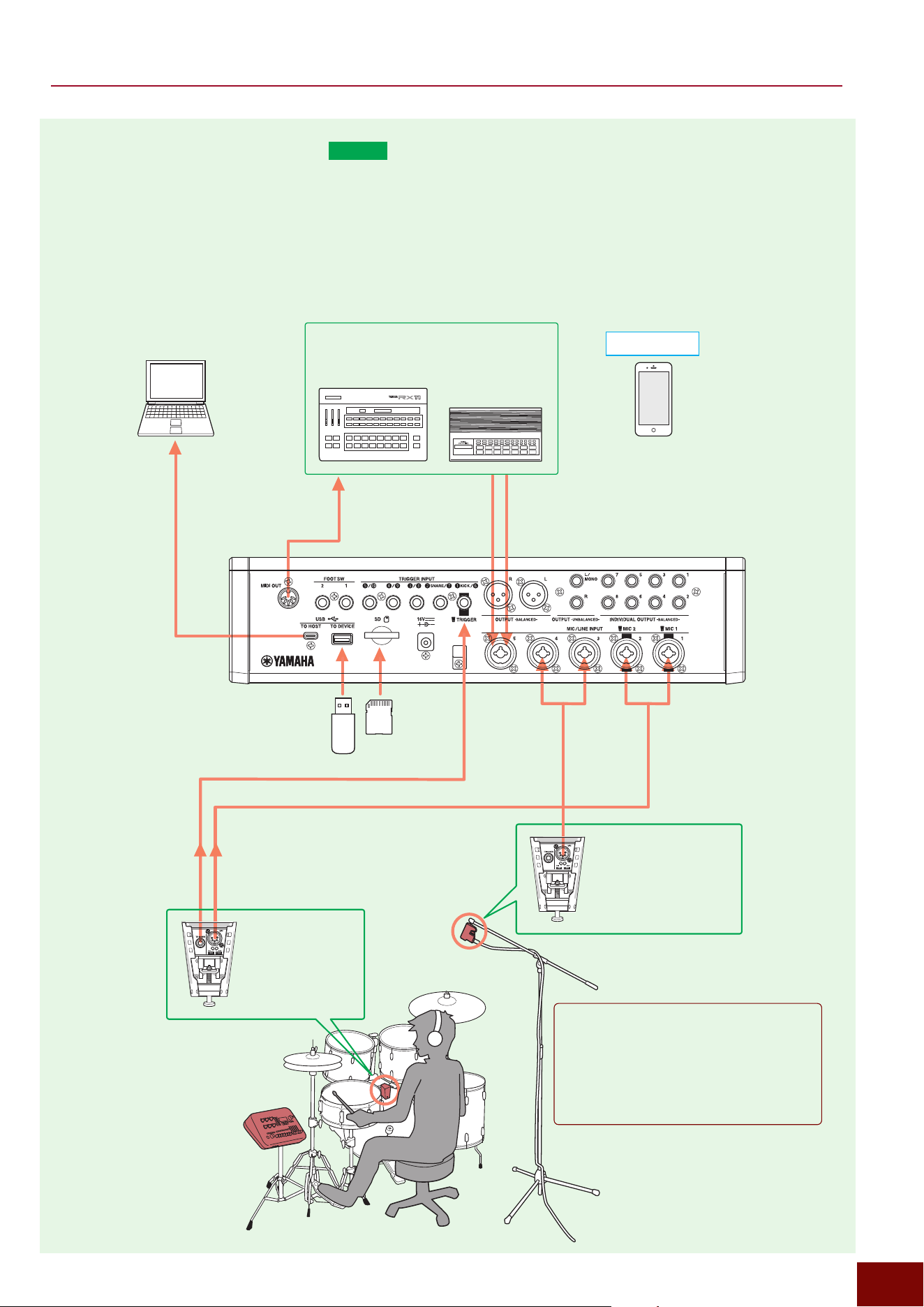
EAD50 EAD20 User Guide
54
Preparation
■ Recording (Studio/Home)
EAD50
All sounds input to this product, including drum performances, can be recorded by the following methods.
z
Recording to Media:
The Recorder function (Page 164) can be used to record sounds on media connected to the product. Use this method for
quick and simple recording.
z
Recording to a Computer:
Sound can be recorded on a computer connected to the product using the DAW software installed on the product. Use this
method for full-featured music production.
EAD50
unit
Vintage rhythm machines from an era without
USB connectors, such as Yamaha RX11 or
RX21 models
[MIC/TRIG]
"
[F3] Setting
"
Kit
"
Voice MIDI
[MENU]
"
USB Audio
"
USB Audio
"
Mode=8in/10out
[MENU]
"
Bluetooth
"
Bluetooth
"
On/Off=On
Line Out
Rear Panel
Media
(for recording
performances)
Included
Sensor Unit
DSU50
Trigger Signals input based on drum performance
Drum performance sound (audio) input
Sensor Unit
DSU50
Additional DSU50 unit
positioned above the
drummer’s head
Tips
Positioning Sensor Unit in front or above and behind
the drummer allows capturing the overall drum
ambience in stereo.
Positioning the sensor in front of the drummer will
reverse the left-right orientation, so swap the Mic3
and Mic4 cable connections.
DAW
EAD Touch
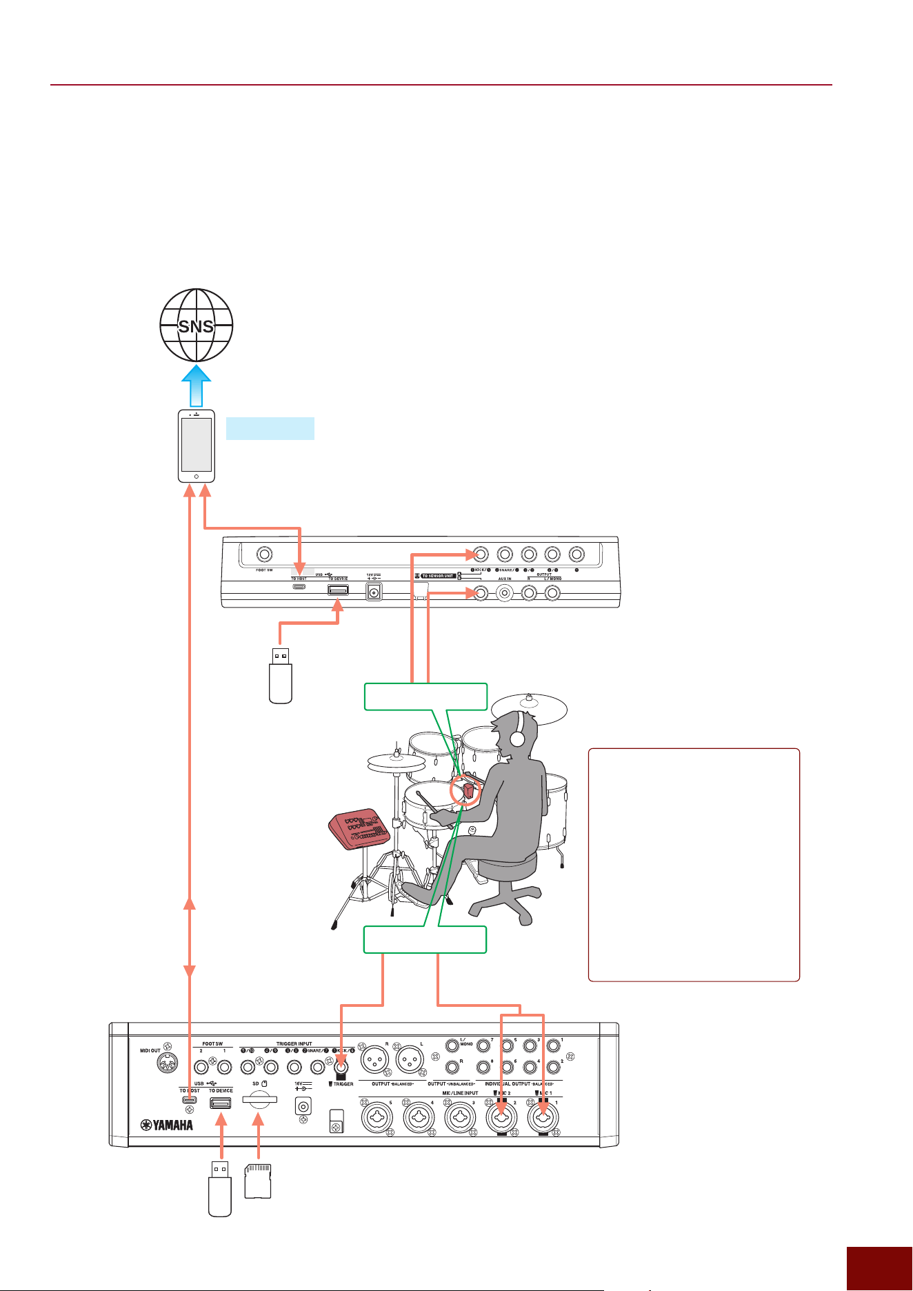
EAD50 EAD20 User Guide
55
Preparation
■ Recording (Streaming Content Production)
By connecting the product to a smartphone/tablet, the camera on respective devices can be used to record video of your own
drum performance and simultaneously record the performance audio using dedicated Rec’n’Share software app. Any song
saved in media or input via the [AUX IN] jack can be recorded with the performance by playing it as a backing track together
with the performance. The Rec'n'Share app can be used to stream recorded performances via the Internet, such as social
media.
Rec’n’Share
Sensor Unit
Sensor Unit
EAD20
Rear Panel
Media
(for playing backing track)
EAD50
Rear Panel
Media
(for playing backing track)
Trigger Signals input based
on drum performance
Trigger Signals
input based on
drum performance
Drummer (audio) input
Drummer (audio) input
Main unit
Tips
In some cases, resonance sound from
a tom drum can enter the sensor unit
microphone, such as when hitting a kick
drum. Though tom resonance is part
of the overall drum sound, if it prevents
achieving the desired sound, the tom
resonance can be adjusted by attaching
a mute to the tom’s top or bottom head
or by using the mic EQ to reduce the
level of the objectionable frequency.
If necessary, another way to reduce the
resonance is to remove the tom’s bottom
head, but doing so will significantly affect
the tone.
(for playing backing track)
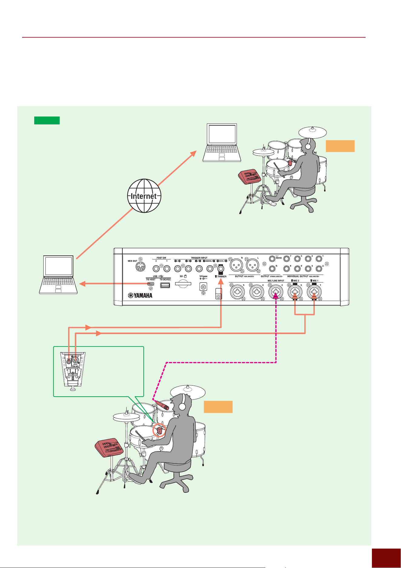
EAD50 EAD20 User Guide
56
Preparation
■ Online Lessons
If the product is connected to a computer via the audio interface and a USB cable, then the various performances and
other sounds recorded in the product can be transmitted via the computer to someone else connected via the Internet. That
functionality can be used to give online lessons to students in remote locations.
[MENU]
"
USB Audio
"
USB Audio
"
Mode=8in/10out
Video Conferencing Tool
EAD50
Rear Panel
Trigger Signals input based on drum performance
Drum performance sound (audio) input
EAD50
unit
Included
Sensor Unit
DSU50
Chat App
Teacher mic audio (or talk) input
[MIC/TRIG]
"
Mic
"
Mic In
"
Talk=on (MicSel=Mic3)
Teacher
Student
EAD50
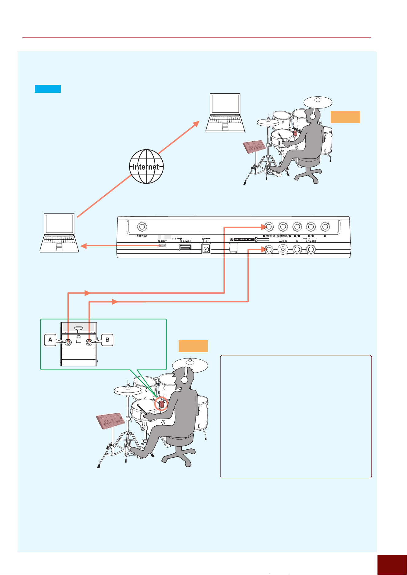
EAD50 EAD20 User Guide
57
Preparation
■ Online Lessons (Continued)
[MENU]
"
USB Audio
"
USB Audio
"
Mode=8in/10out
Video Conferencing Tool
EAD20
Rear Panel
Trigger Signals input based on drum performance
Drum performance sound (audio) input
EAD20
unit
EAD20
Included with
EAD20
Sensor Unit
Chat App
Teacher
Student
This product offers the following methods for easily
switching the Sensor Unit mic section between the
performance and talk modes.
z
Switch Modes by Operating the Modifier Knob
(Page 78)
[SCENE]
"
[F1] ModSel
"
Function=Talk On/Off
z
Switch Modes by Operating an Electronic Drum
Pad or Foot Switch (Page 142)
[MIC/TRIG]
"
[F3] Setting
"
Kit
"
Voice
"
Voice Func
"
Function=Talk Control
These settings allow easily switching between
talking by the performer and student, without
having to have a dedicated microphone for talking.

EAD50 EAD20 User Guide
58
Preparation
Turning the Power On and Off
For detailed instructions, including connecting the AC adapter, refer to the Quick Guide.
Checking the Version
The product version can be confirmed by pressing [MENU]
"
Version
"
[ENTER].
The latest version for this product can be downloaded from [Software] on the following website.
https://download.yamaha.com/
Yamaha recommends always keeping the software updated to the latest version.
Note that the descriptions in this manual are consistent with the version that was current when the manual was created.
Auto Power Off (Automatically Turns Off the Power)
The Auto Power Off function automatically turns off the power supply if no operations are performed for a specified period. That
period is factory set to 15 minutes when shipped.
NOTICE
• Depending on the product status, the power might not turn off even after not performing any operations for the specified Auto Power Off
period. In that case, turn off this product manually after using the product.
• If an external audio device or PA device will be connected to this product without performing any operations for a specified period, it is
recommended that the volume on the external audio device be left adjusted to zero.
• If this product was turned off by the Auto Power Off function, then any data recorded in internal memory (Page 33) by the Recorder,
Looper, or Sampling function will be lost. Therefore, be sure to save any valuable data before it is lost.
NOTE
Even if the Auto Power Off function turns off this product, previous settings and edits will be retained and not deleted. The next time the
power is turned on, continue configuring settings/edits and save the changes as necessary.
■ Changing the Auto Power Off Setting
Depending on live performance, recording, and other circumstances, the default setting of 15 minutes might feel too short. If
so, use the following screen to change the setting for the elapsed time before power is automatically turned off.
[MENU]
"
Utility
"
Auto Power Off
■ Canceling the Auto Power Off Function
The Auto Power Off function can be canceled by any of the following methods. Regardless of the method used, the Auto Power
Off function will remain canceled even after turning the power on the next time.
• To switch off the function, set [MENU]
"
Utility
"
Auto Power Off = Off.
• If the power is off and the standby/on button is pressed while pressing the [MENU] button, this product will restart with the Auto
Power Off function canceled.

EAD50 EAD20 User Guide
59
Preparation
Restoring Default Factory Settings (Factory Reset)
Even if the settings were accidentally overwritten, factory default settings can be restored by executing the Factory Reset
function.
There are two ways to restore settings.
• Restore settings by pressing [MENU]
"
Factory Reset
"
[ENTER].
• If the power is off, pressing the standby/on switch while simultaneously pressing [+] and [−] buttons will start up this product.
NOTICE
The factory reset function will delete all data and restore all settings to their default state. Be sure to save all valuable data in a USB flash
drive or SD card before restoring factory settings.
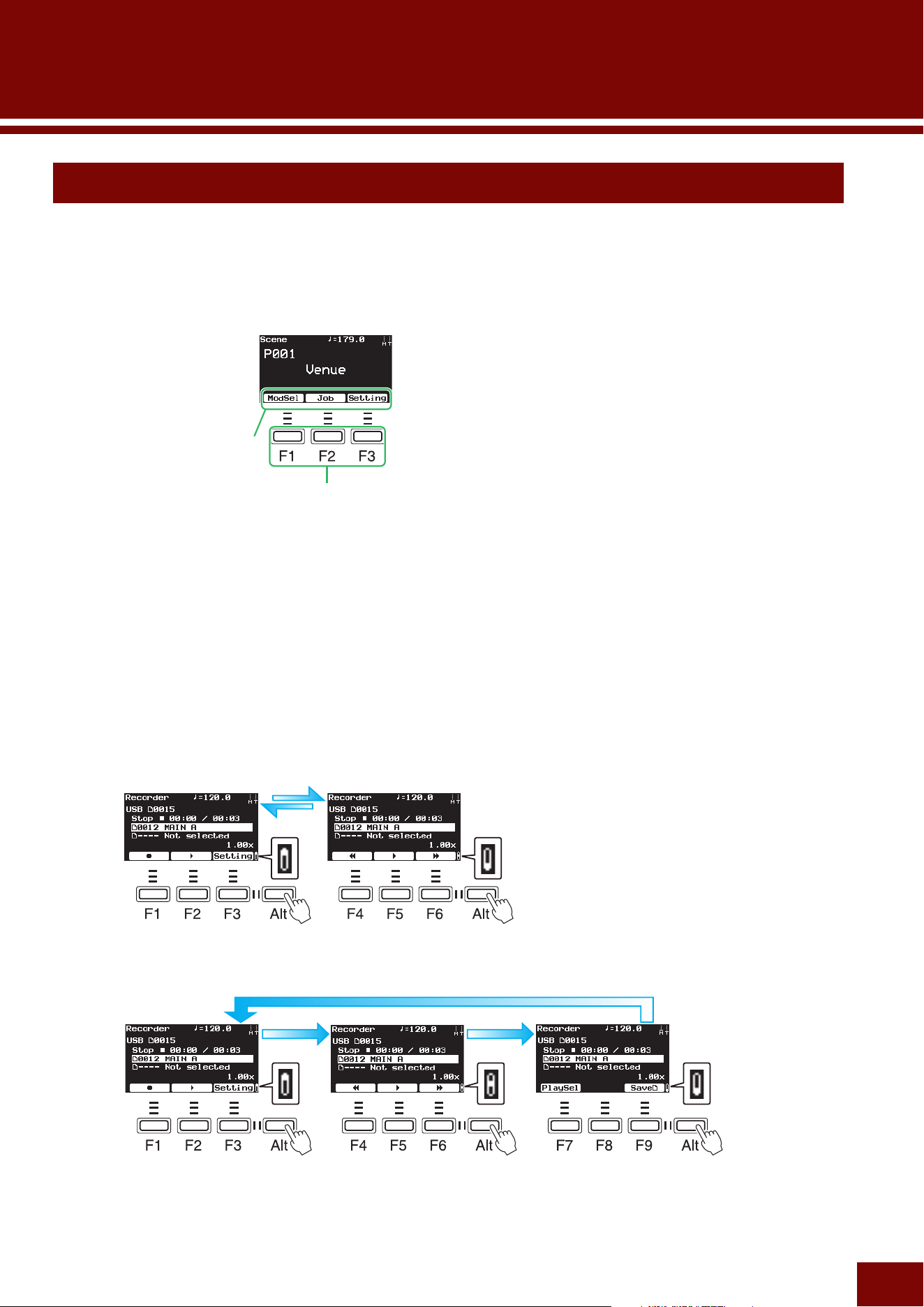
EAD50 EAD20 User Guide
60
Basic Screen Operations
■ Function Buttons at the Bottom of the Screen and [F] Buttons Below the Screen
The three buttons below the screen link to the functions displayed along the bottom of the screen. Pressing an [F] button
executes the corresponding function or displays the corresponding screen. Though the [F] buttons do not have specific
names, for explanatory convenience they are referred to as [F1], [F2], and [F3] buttons, where “F” refers to “Function.”
[F] (function) buttons
Function
names
■ [Alt] Button Used to Change [F] Button Functions
When simply pressing an [F1] – [F3] is not sufficient to execute the displayed function, the button shown to the right of the [F]
buttons can be pressed to switch to the functions corresponding to the [F] buttons. This function-switching button is not named
either, so for explanatory convenience it is referred to as the [Alt] button. Furthermore, also for explanatory convenience, the [F]
buttons are referred to as follows after switching functions.
• [F] button names corresponding to function names (first set): [F1], [F2], and [F3]
• [F] button names corresponding to function names (second set): [F4], [F5], and [F6]
• [F] button names corresponding to function names (third set): [F7], [F8], and [F9]
• Name of button for switching [F] button numbers: [Alt]
First Second
Assuming [F1] to [F6]
Assuming [F1] to [F9]
First Second Third
Basic Operations
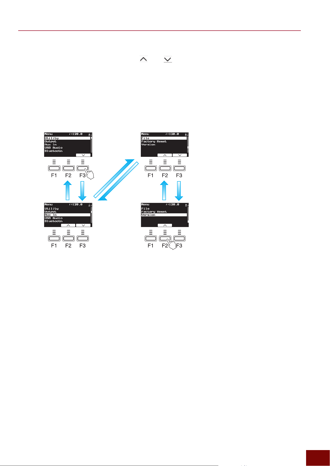
EAD50 EAD20 User Guide
61
Basic Operations
■ Moving the Cursor and Changing Pages
On the screen where settings are listed, press the [F2] or [F3] buttons at the bottom of the screen to move the cursor.
For some functions, not all setting parameters can be listed within one screen, so a scroll bar is displayed along the right edge
of the screen to indicate that parameters are listed on multiple pages. In that case, use the [F2] and [F3] buttons to move the
cursor to the next or previous page.
NOTE
The “F” in “F1 – F3” refers to “Function” and is used to name the buttons for explanatory convenience. The names are not printed on the
panel.
If the cursor is located at the first
setting on the first page
If the cursor is located at the first
setting on the second page
If the cursor is located at the last
setting
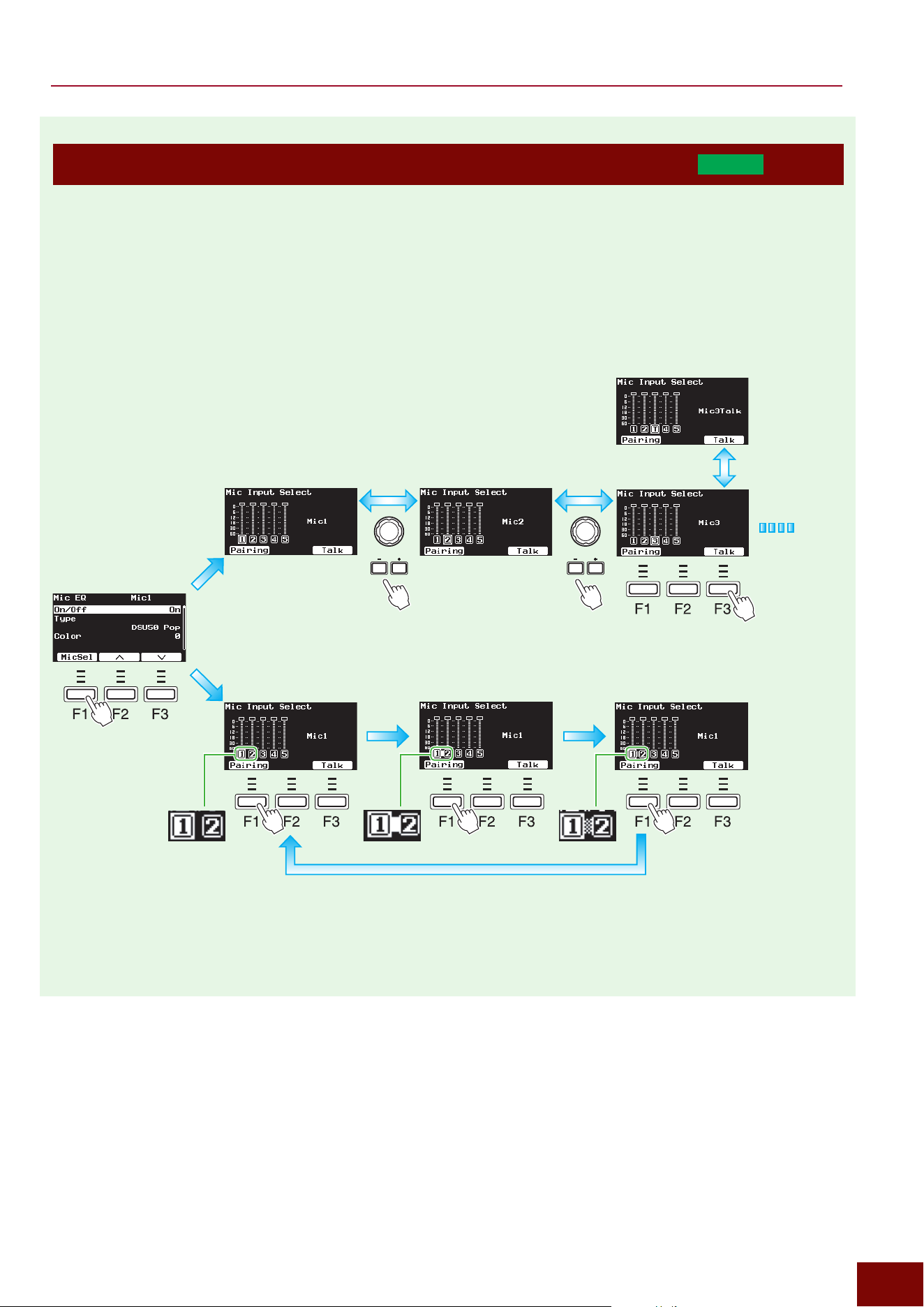
EAD50 EAD20 User Guide
62
Basic Operations
Selecting and Basic Settings for Input Sources—Mic Sounds (
EAD50
only)
The setting screens for the mic input sounds indicated below require pressing the [F1] (MicSel) button to select from [MIC/
LINE] jacks 1 to 5 to specify the jacks to which the setting is to be applied. They also require specifying the basic settings,
such as the mic application and stereo pairing settings.
[MIC/TRIG]
"
[F3] Setting
"
Mic
"
Mic In, Mic EQ, Mic TransComp, Mic Out
[MIC/TRIG]
"
[F3] Setting
"
Effect
"
Reverb, FX1, FX2
"
Send Mic, Send Mic Curve
[MIC/TRIG]
"
[F3] Setting
"
Effect
"
Dry
"
Level Mic, Level Mic Curve
[MIC/TRIG]
"
[F3] Setting
"
Effect
"
Ins1 Mic, Ins2 Mic
NOTE
The “F” in “F1 – F3” refers to “Function” and
is used to name the buttons for explanatory
convenience. The names are not printed on the
panel.
Equivalent to [MIC/TRIG]
"
[F3]
Setting
"
Mic
"
Mic Pairing =
Separate
Equivalent to [MIC/TRIG]
"
[F3]
Setting
"
Mic
"
Mic Pairing = Paired
Equivalent to [MIC/TRIG]
"
[F3]
Setting
"
Mic
"
Mic Pairing =
Paired Excep Gain
n
Set/Cancel Mic Stereo Pairings
n
Select Microphones
Apply setting to Mic 1 Apply setting to Mic 2 Apply setting to Mic 3
n
Switch Talk Setting On/Off
In this example,
talk settings can
be switched on/off
individually for all
mics, not just for
Mic 3.
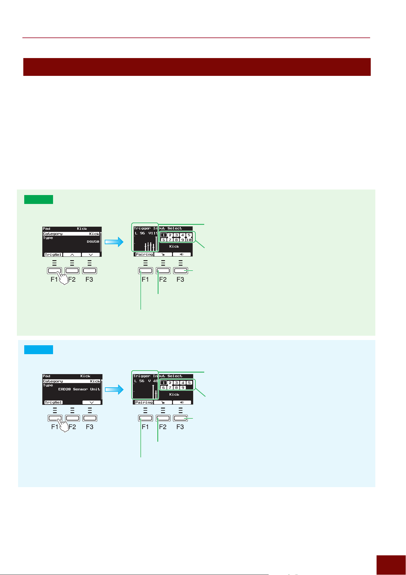
EAD50 EAD20 User Guide
63
Basic Operations
Selecting Input Sources and Basic Settings—Trigger Signals
The setting screens for Trigger Inputs require pressing the [F1] (TrigSel) button to select Trigger Inputs (pads, Insts, or Voices)
for applying the setting.
■ Pad/Inst Settings (Select from Trigger Input Jacks)
[MIC/TRIG]
"
[
F3] Setting
"
Trigger
"
Trig In
"
Pad, Vel Curve, Crosstalk
[MIC/TRIG]
"
[F3] Setting
"
Kit
"
Inst
"
Inst, Inst EQ, InstTranComp, Inst Out
[MIC/TRIG]
"
[F3] Setting
"
Effect
"
Reverb, FX1, FX2
"
Send Trig, Send Trig Curve
[MIC/TRIG]
"
[F3] Setting
"
Effect
"
Real Ambi
"
Depth Trig, Depth Trig Curve
[MIC/TRIG]
"
[F3] Setting
"
Effect
"
Dry
"
Level Trig, Level Trig Curve
[MIC/TRIG]
"
[F3] Setting
"
Effect
"
Ins Trig
EAD50
Specifies whether to pair mics 1 and 6, 2 and 7, 3
and 8, 4 and 9, or 5 and 10.
Pad Lock:
Prevents the pad selection from
changing when the pad is hit.
Audition:
Produces the Inst sound assigned to the currently-selected Trigger Input.
The volume level can be adjusted on the following screen (Page 188).
[MENU]
"
Utility
"
Audition Velocity
Trigger Input Source: Select using [+]/[−] buttons.
The following two are displayed in real time.
L (bar graph): Trigger Input level
V (height of horizontal line): Pad hitting force
(velocity)
NOTE
The “F” in “F1 – F3” refers to “Function” and
is used to name the buttons for explanatory
convenience. The names are not printed on
the panel.
z
Trigger Input Selection screen
EAD20
Sets whether to pair mics 1 and 6, 2 and 7, 3 and 8, or
4 and 9.
Pad Lock:
Prevents the pad selection from
changing when the pad is hit.
Audition:
Produces the Inst sound assigned to the currently-selected Trigger
Input. The volume level can be adjusted on the following screen (Page 188).
[MENU]
"
Utility
"
Audition Velocity
Trigger Input Source: Select using [+]/[−] buttons.
The following two are displayed in real time.
L (bar graph): Trigger Input level
V (height of horizontal line): Pad hitting force (velocity)
NOTE
The “F” in “F1 – F3” refers to “Function” and
is used to name the buttons for explanatory
convenience. The names are not printed on
the panel.
z
Trigger Input Selection screen
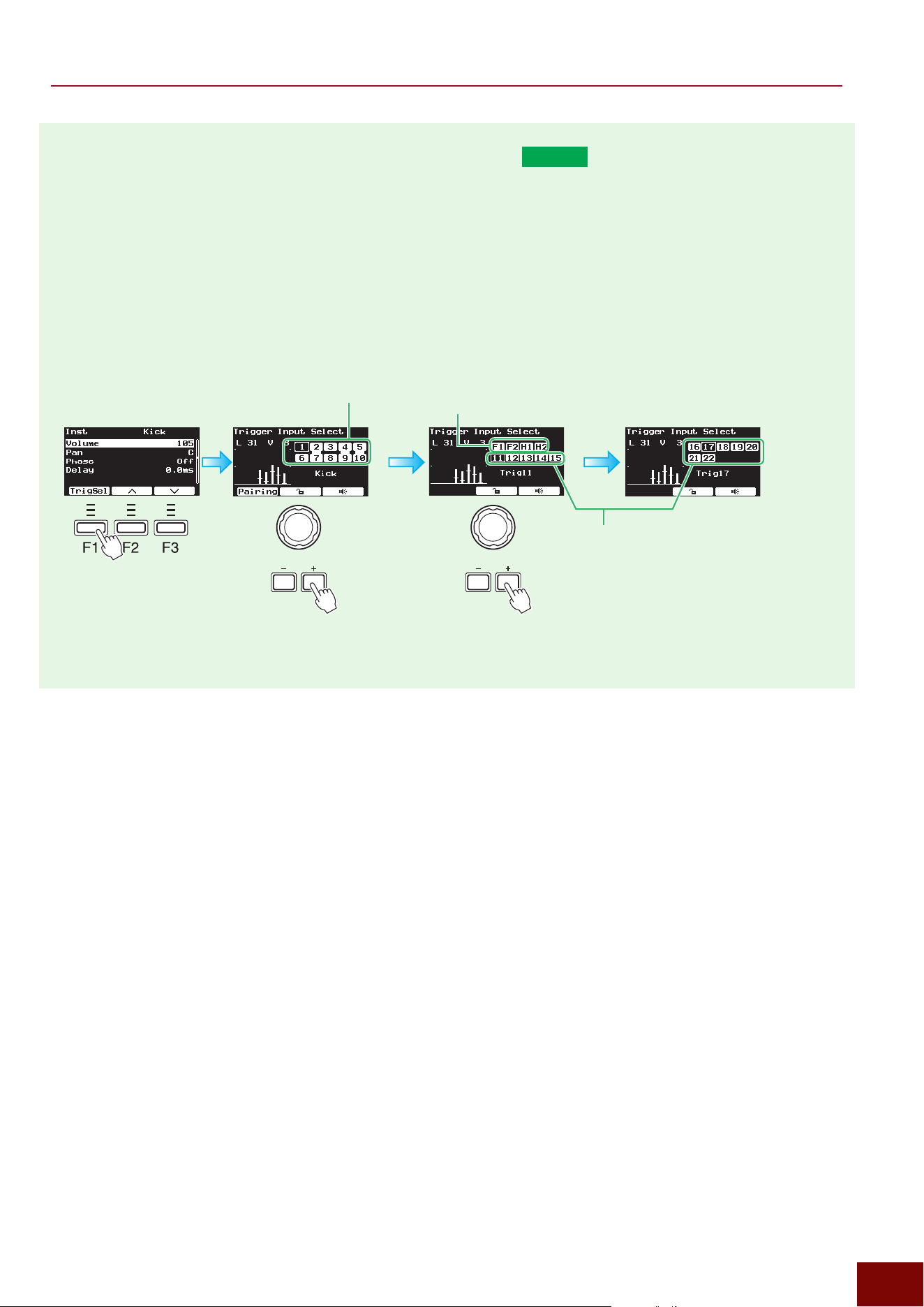
EAD50 EAD20 User Guide
64
Basic Operations
■ Inst Settings (Select from MIDI Trigger Inputs)
EAD50
[MIC/TRIG]
"
[F3] Setting
"
Kit
"
Inst
"
Inst, Inst EQ, InstTranComp, Inst Out
[MIC/TRIG]
"
[F3] Setting
"
Effect
"
Reverb, FX1, FX2
"
Send Trig, Send Trig Curve
[MIC/TRIG]
"
[F3] Setting
"
Effect
"
Real Ambi
"
Depth Trig, Depth Trig Curve
[MIC/TRIG]
"
[F3] Setting
"
Effect
"
Dry
"
Level Trig, Level Trig Curve
[MIC/TRIG]
"
[F3] Setting
"
Effect
"
Ins Trig
NOTE
The pad lock function assigned to the [F2]
button and the audition function assigned to
the [F3] button are the same as described in
“Pad Settings”. However, if HH Trig In = Off
and the cursor is positioned on [H1] or [H2],
then the audition function is disabled and the
[F3] button is not displayed.
Trigger signals are generated based on signals input
from a foot switch connected to this product. The
setting steps shown below change the display to
showing F1 and F2 or H1 and H2.
[MIC/TRIG]
"
[F3] Settings
"
Trigger
"
Trig In
"
Foot Sw1, Foot Sw2
"
HH Trig In
NOTE
The “F” in “F1 – F3” refers to “Function” and
is used to name the buttons for explanatory
convenience. The names are not printed on the
panel.
Trigger Inputs for pads
connected to this product.
Trigger Inputs by MIDI from
an external device
z
Trigger Input Selection screen
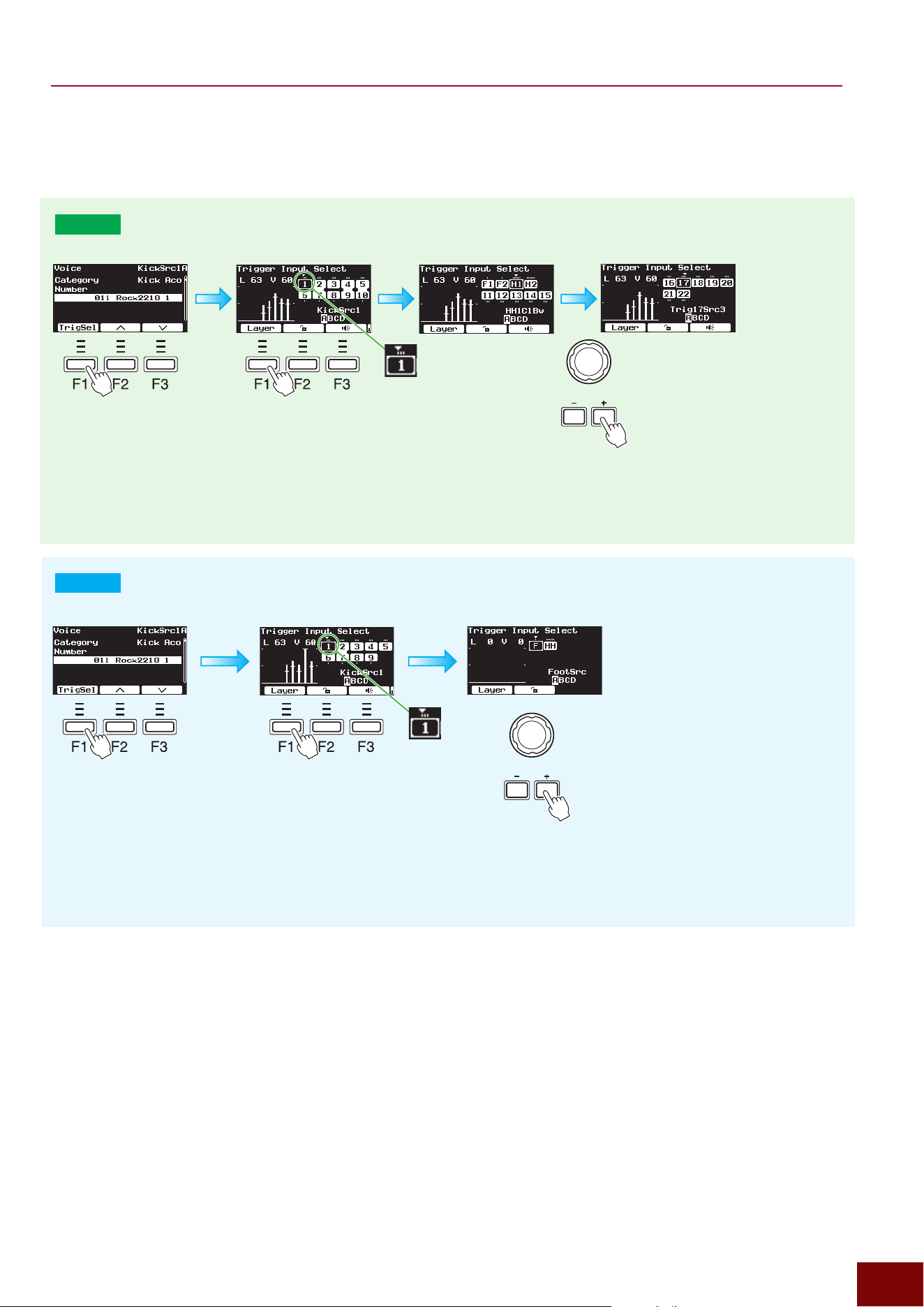
EAD50 EAD20 User Guide
65
Basic Operations
■ Voice Settings (Select Trigger Input Sources)
[MIC/TRIG] "[F3] Setting "Kit "Voice "Voice, Voice MIDI, Voice Func
EAD50
NOTE
The “F” in “F1 – F3” refers
to “Function” and is used
to name the buttons for
explanatory convenience. The
names are not printed on the
panel.
Successively select the
Trigger Input Source using
the [+]/[−] buttons or knob.
Use the [F1] Layer
button to select from
layers A to D for each
Trigger Input Source.
EAD20
NOTE
The “F” in “F1 – F3” refers to
“Function” and is used to name
the buttons for explanatory
convenience. The names are not
printed on the panel.
Successively select
the Trigger Input
Source using the [+]/
[−] buttons or knob.
Use the [F1] Layer
button to select from
layers A to D for each
Trigger Input Source.
NOTE
The pad lock function assigned to the [F2] button and the audition function
assigned to the [F3] button are the same as described in “Pad Settings”.
However, if HH Trig In = Off and the cursor is positioned on [H1] or [H2],
then the audition function is disabled and the [F3] button is not displayed.
NOTE
The pad lock function assigned to the [F2] button and the audition function
assigned to the [F3] button are the same as described in “Pad Settings”.
However, if HH Trig In = Off and the cursor is positioned on [H1] or [H2],
then the audition function is disabled and the [F3] button is not displayed.
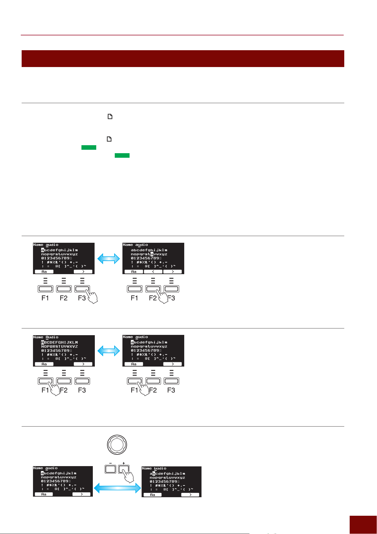
EAD50 EAD20 User Guide
66
Basic Operations
Naming Data
Data created on this product can be named on the screens listed below. The following operation steps are the same for all the
screens.
Screen Function
• [SCENE] Other
"
[STORE] .......................................... Sets the Scene name (Name and SubName)
• [RECORDER] (Sampling)
"
[F6] Save
"
[F1] Name
....Sets the file name for saving Sampling data in a USB flash drive or SD card
• [RECORDER] (Sampling)
"
[F9] Save WM
"
[F1] Name
...Sets the User Voice name and User Voice bank name when assigning User Voices to
recorded sample data
• [RECORDER] (Looper)
"
[F6] Save
"
[F1] Name
...Sets the file name for saving Looper data in a USB flash drive or SD card
• [LIVE SET]
"
[STORE] (
EAD50
only
) ..........................Sets the Live Set name (Name and SubName)
• [LIVE SET]
"
[F3] Setting
"
[F1] Name (
EAD50
only
) ... Sets the Live Set step name
• [MENU]
"
File
"
File All
"
Save
"
[F1] Name ..............Sets the file name for saving all data created with this product in media (USB flash drive)
• [MENU]
"
File
"
File All
"
Rename
"
[F1] Name ......... Changes the file name for saving all data created with this product in media (external
memory)
• [MENU]
"
File
"
File Scene
"
Save
"
[F1] Name ........Sets the file name for saving Scene data created with this product in media (external
memory)
• [MENU]
"
File
"
File Scene
"
Rename
"
[F1] Name ..Changes the file name of Scene data in media (external memory)
• [MENU]
"
File
"
File Wave
"
Rename
"
[F1] Name .... Changes the file name of audio files in media (external memory)
1. Move the name cursor (top row).
2. If necessary, switch between upper/lower case.
3. Change the character at the name cursor position (top row).
NOTE
The “F” in “F1 – F3” refers to “Function” and
is used to name the buttons for explanatory
convenience. The names are not printed on the
panel.
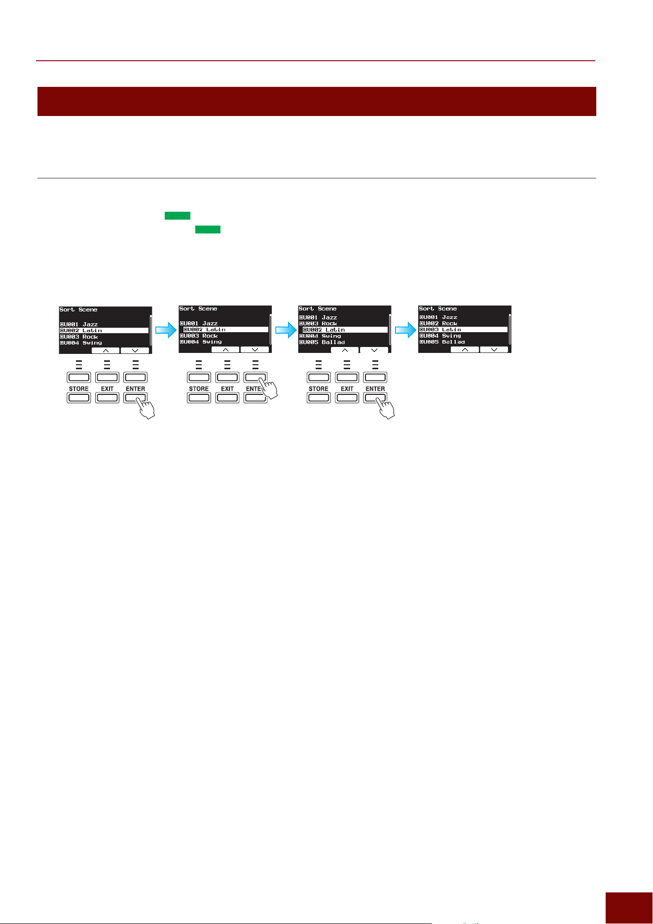
EAD50 EAD20 User Guide
67
Basic Operations
Changing the Data Order
Data can be sorted or its order changed on the following screens. The following operation steps are the same for all the
screens.
Screen Function
• [MIC/TRIG]
"
[F3] Setting
"
Kit
"
User Voice
"
Sort Wave.. Sorts the waveform data loaded (imported) into the product
• [SCENE]
"
[F2] Job
"
Sort ................................................ Changes the order of Scenes.
• [LIVE SET]
"
[F2] Job
"
Sort (
EAD50
only
) ...................... Changes the order of Live Sets
• [LIVE SET]
"
[F3] Setting
"
[F4] Sort (
EAD50
only
) .......... Changes the order of steps within each Live Set
That switches the set order for items previously
ordered 02 and 03.
1.
With the cursor positioned on the
desired parameter for moving,
press the [ENTER] button. The
parameter where the cursor is
positioned becomes indented.
2.
Use the [F2]/[F3] buttons to
move to the parameter selected
in step 1.
3.
When positioned in the
movement location specified
in step 2, press the [ENTER]
button. That applies the sorted
order.
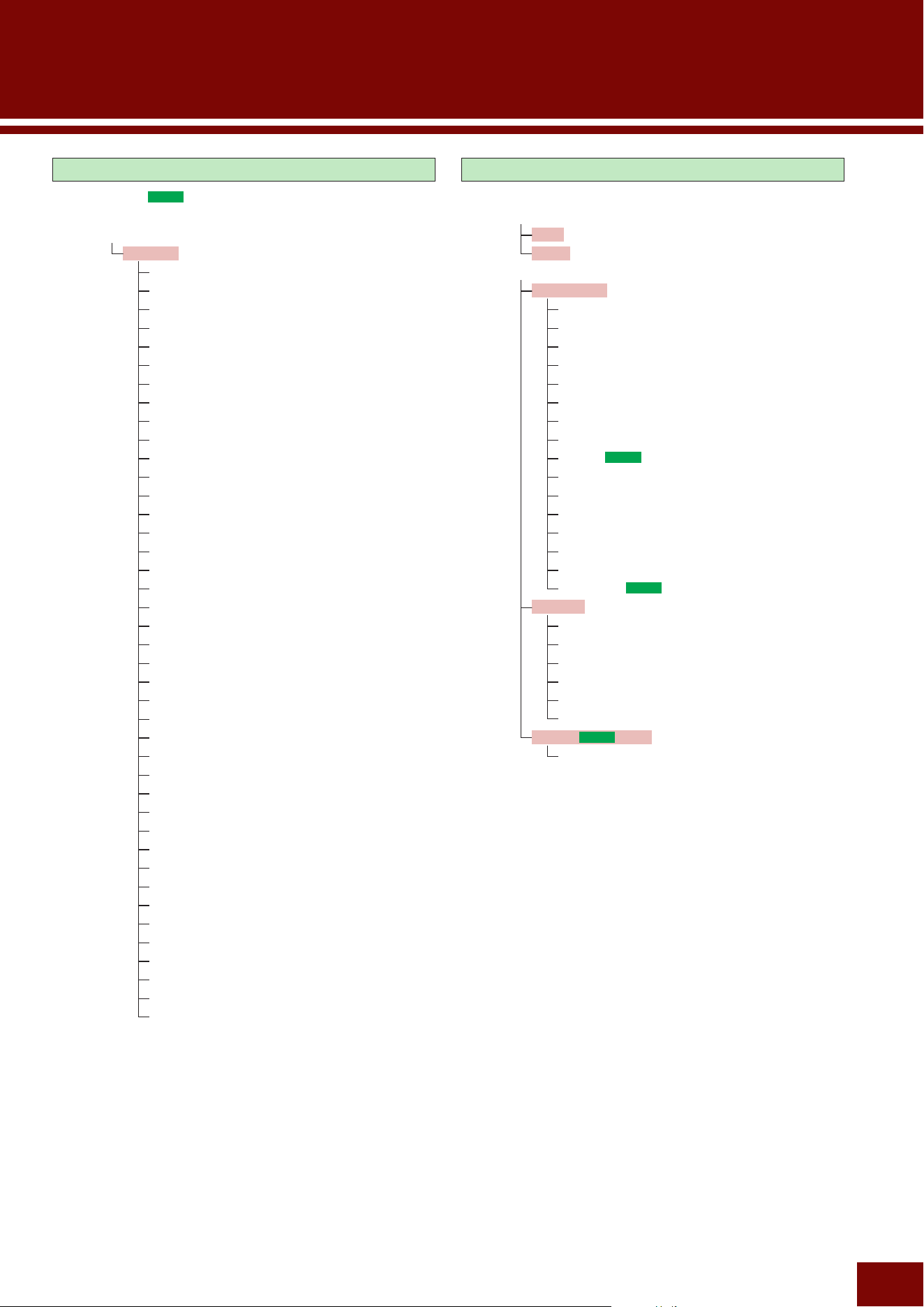
EAD50 EAD20 User Guide
68
Modifier Knob Operations
[F1] MicSel (
EAD50
only) or TrigSel
[F2] Effect, Type, Inst, etc.
[F3] Setting
Function
Off
Tempo
Talk On/Off
Mic EQ Color
Mic Tran Comp Depth
Mic Tran Attack
Mic Tran Release
Xstick On/Off
Inst Number
Inst Volume
Inst Pan
Inst Tuning/Size
Inst Attack
Inst Muffling/Sustain/Decay
Inst EQ Color
Inst Tran Comp Depth
Inst Tran Attack
Inst Tran Release
Voice Volume
Effect Depth
Reverb Param A
Reverb Param B
Reverb Param C
FX1 Param A
FX1 Param B
FX1 Param C
FX2 Param A
FX2 Param B
FX2 Param C
Ins1 Mic Depth
Ins1 Mic Param A
Ins1 Mic Param B
Ins1 Mic Param C
Ins2 Mic Depth
Ins2 Mic Param A
Ins2 Mic Param B
Ins2 Mic Param C
Ins Trig Depth
Ins Trig Param A
Ins Trig Param B
Ins Trig Param C
Function Tree Diagram
[SCENE]
[F1] ModSel
[F2] Job
Sort
Clear
[F3] Setting
Scene Load
Mic/Kit Volume
Mic
Trigger
Kit
Function
Effect
Tempo
Modifier
Fader (
EAD50
only)
Click
Recorder
Utility
Output
Aux In
USB Audio
Bluetooth (
EAD50
only)
Modifier
Modifier Pop-up
CC Number
CC Channel
CC Port
CC Min Value
CC Max Value
Fader (
EAD50
only)
Fader Pop-up
[STORE]
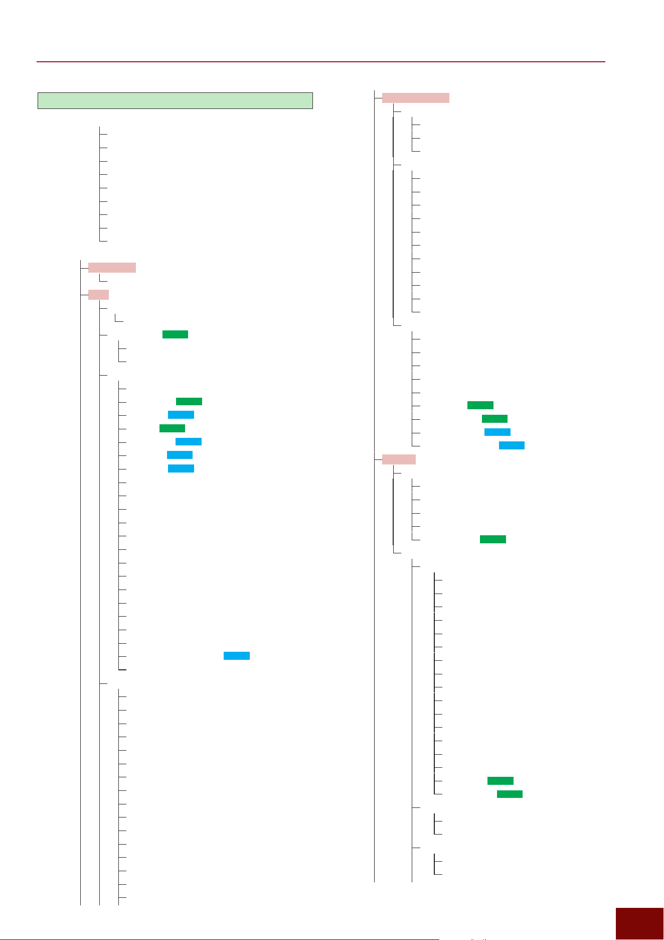
EAD50 EAD20 User Guide
69
Function Tree Diagram
[MIC/TRIG]
[F1] Volume
Mic/Kit
Mic
Mic In
Kit
Inst
Voice A
Voice B
Voice C
Voice D
[F3] Setting
Mic/Kit Vol
Volume
Mic
Mic Volume
Volume
Mic Pairing (
EAD50
only)
Mic1/2
Mic3/4
Mic In
On/Off
Phantom (
EAD50
only)
Pairing (
EAD20
only)
Gain (
EAD50
only)
Gain L/R (
EAD20
only)
Gain L (
EAD20
only)
Gain R (
EAD20
only)
Gain Auto Setup
Volume
Pan
Phase
Delay
Gate
Gate Threshold
Gate Hold
Gate Attack
Gate Release
Noise Gate
Noise Gate Thr
Noise Gate Rel
JackNoise Reduction (
EAD20
only)
Talk
Mic EQ
On/Off
Type
Color
Low Freq
Low Gain
Low Q
Low Shape
MidLow Freq
MidLow Gain
MidLow Q
MidHigh Freq
MidHigh Gain
MidHigh Q
High Freq
High Gain
High Q
Mic (continued)
Mic EQ (continued)
High Shape
HPF Freq
HPF Q
Mic TranComp
On/Off
Type
Depth
Tran Attack
Tran Release
Tran Sensitivity
Comp Threshold
Comp Ratio
Comp Attack
Comp Release
Comp Out Level
Mic Out
EQ Tran Thru
Effect Thru
Main Out
Phones Out
USB Audio Out 1/2
IndivOut (
EAD50
only)
IndivOut Vol (
EAD50
only)
USB AudOut (
EAD20
only)
USB AudOut Vol (
EAD20
only)
Trigger
Trig Pairing
Kick/Trig6
Snare/Trig7
Trig3/Trig8
Trig4/Trig9
Trig5/Trig10 (
EAD50
only)
Trig In
Pad
Category
Type
Gain
Rim Gain
H/R Balance
Gain Auto Setup
Wait Time
Reject Time
Sensitivity
Min Level
Max Level
Min Velocity
Max Velocity
Xstick On/Off
Xstick Adjust
Position (
EAD50
only)
Attenuator (
EAD50
only)
Vel Curve
Curve
X1, Y1, X2, Y2
Crosstalk
Auto Setup
Reject Level
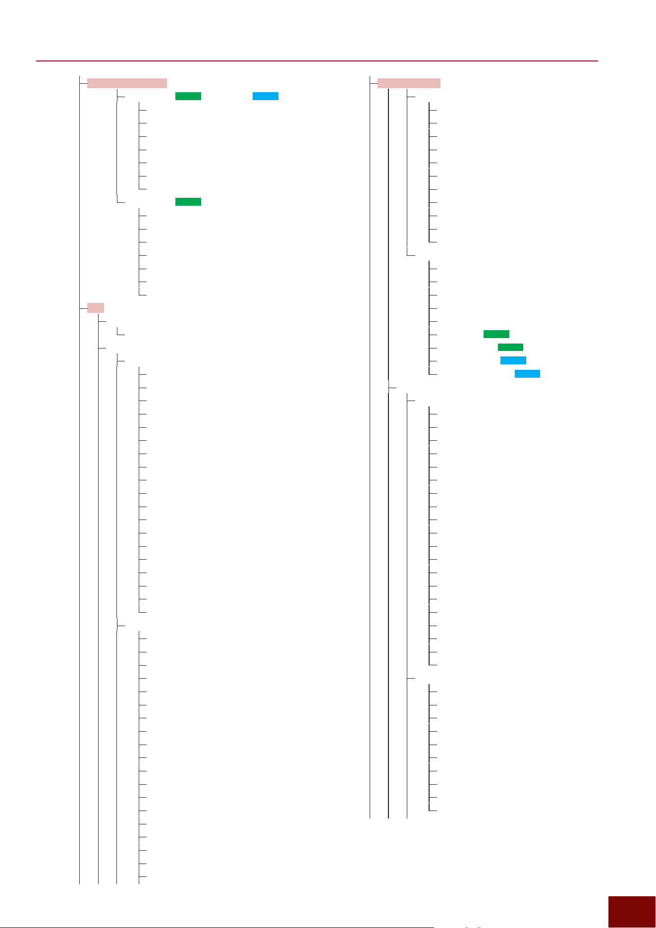
EAD50 EAD20 User Guide
70
Function Tree Diagram
Kit (continued)
InstTranComp
On/Off
Type
Depth
Tran Attack
Tran Release
Tran Sensitivity
Comp Threshold
Comp Ratio
Comp Attack
Comp Release
Comp Out Level
Inst Out
EQ Tran Thru
Effect Thru
Main Out
Phones Out
USB Audio Out 1/2
IndivOut (
EAD50
only)
IndivOut Vol (
EAD50
only)
USB AudOut (
EAD20
only)
USB AudOut Vol (
EAD20
only)
Voice
Voice
Category
Number
Volume
Pan
Tuning
Attack
Decay
Cutoff
Resonance
Mono/Poly
Choke Send
Choke Receive
Humanize
Fixed Velocity
Hold Mode
Layer Mode
Velocity Limit Low
Velocity Limit High
Velocity Fade Low
Velocity Fade High
Voice MIDI
Note Num 1–4
Note Ch 1–4
Note Port
Note Gate Time
CC Number Note
CC Number Position
CC Channel
CC Port
CC Min Value
CC Max Value
Trigger (continued)
Foot Sw1 (
EAD50
), Foot Sw (
EAD20
)
Type
HH Trig In
HH Pitch Up
HH Clutch Pos
Foot Close Pos
Foot Close Vel
Foot Splash Sens
Foot Sw2 (
EAD50
only)
Type
HH Trig In
HH Pitch Up
HH Clutch Pos
Foot Close Pos
Foot Close Vel
Foot Splash Sens
Kit
Kit Volume
Volume
Inst
Inst
On/Off
Category
Number
Import Wave
Volume
Pan
Phase
Delay
Tuning
Size
Attack
Muffling
Sustain
Decay
Gate
Gate Threshold
Gate Hold
Gate Attack
Gate Release
Inst EQ
On/Off
Type
Color
Low Freq
Low Gain
Low Q
Low Shape
MidLow Freq
MidLow Gain
MidLow Q
MidHigh Freq
MidHigh Gain
MidHigh Q
High Freq
High Gain
High Q
High Shape
HPF Freq
HPF Q
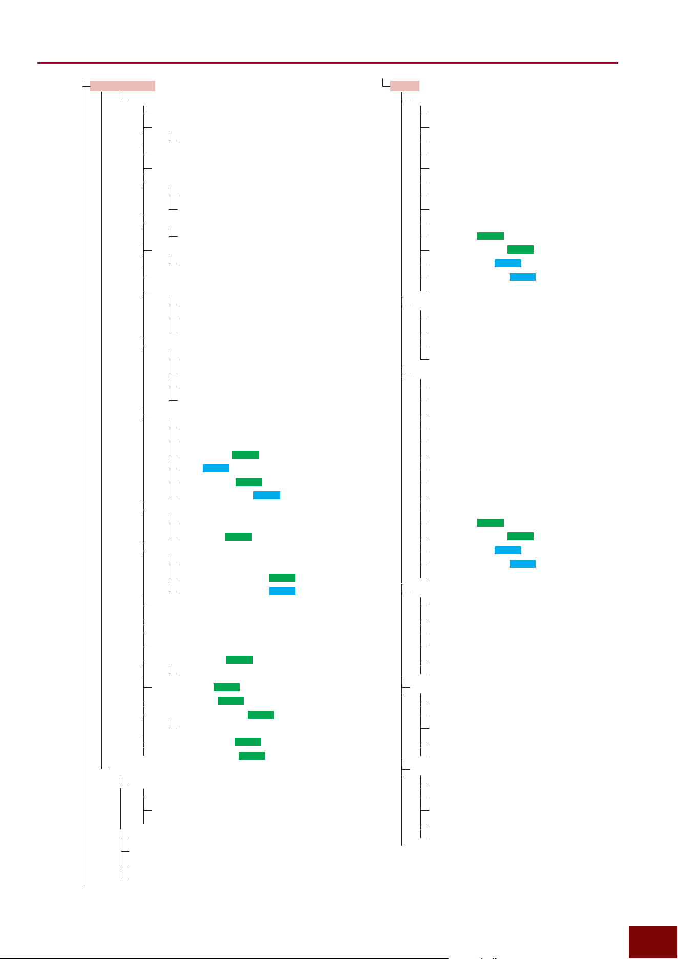
EAD50 EAD20 User Guide
71
Function Tree Diagram
Kit (continued)
Voice Func
Off
Scene Select
Scene Number
Scene Inc
Scene Dec
Scene Toggle
Scene Number A
Scene Number B
Tempo Inc
Value
Tempo Dec
Value
Tempo Tap
Tempo Control
Control Type
Min Value
Max Value
Modifier Control
Control Type
Min Value
Max Value
Modifier1–6
Mic/Trig Control
Control Type
Reverb–Master EQ
Mic1–Mic5 (
EAD50
)
Mic (
EAD20
)
Kick–Trig22 (
EAD50
)
Kick–Tr i g 9, Foot (
EAD20
)
Talk Control
Control Type
Mic Input (
EAD50
only)
Xstick Control
Control Type
Kick, Snare, Trig3–5 (
EAD50
)
Kick, Snare, Trig3–4 (
EAD20
)
Sound Off
Click Start/Stop
Recorder Control A
Recorder Control B
Live Set Select (
EAD50
only)
Live Set Number
Live Set Inc (
EAD50
only)
Live Set Dec (
EAD50
only)
Live Set Step Select (
EAD50
only)
Live Set Step Number)
Live Set Step Inc (
EAD50
only)
Live Set Step Dec (
EAD50
only)
User Voice
Import Wave
File to Bank
Files to Voices
Files by Name
Edit Velocity Limit L/H
Sort Wave
Delete Wave
WaveMem Info
Effect
Reverb
On/Off
Category
Type
Send All
Send Mic
Send Mic Curve
Send Trig
Send Trig Curve
Return
IndivOut (
EAD50
only)
Return IndivOut (
EAD50
only)
USB AudOut (
EAD20
only)
USB AudOut Vol (
EAD20
only)
Parameters 1–24
Real Ambi
On/Off
Depth All
Depth Trig
Depth Trig Curve
FX1, FX2
On/Off
Category
Type
Send All
Send Mic
Send Mic Curve
Send Trig
Send Trig Curve
Send to Reverb
Return
IndivOut (
EAD50
only)
Return IndivOut (
EAD50
only)
USB AudOut (
EAD20
only)
USB AudOut Vol (
EAD20
only)
Parameters 1–32
Dry
On/Off
Level All
Level Mic
Level Mic Curve
Level Trig
Level Trig Curve
Ins1 Mic, Ins2 Mic
On/Off
Category
Type
Depth
Parameters 1–32
Ins Trig
On/Off
Category
Type
Depth
Parameters 1–32
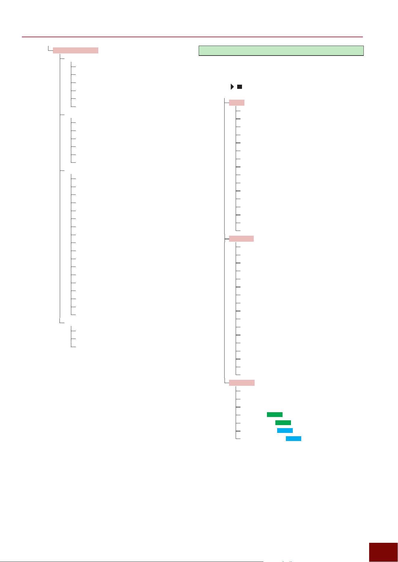
EAD50 EAD20 User Guide
72
Function Tree Diagram
Effect (continued)
Master FX
On/Off
Category
Type
Depth
Depth Curve
Parameters 1–32
Master Comp
On/Off
Category
Type
Depth
Depth Curve
Parameters 1–32
Master EQ
On/Off
Low Freq
Low Gain
Low Q
Low Shape
MidLow Freq
MidLow Gain
MidLow Q
Mid Freq
Mid Gain
Mid Q
MidHigh Freq
MidHigh Gain
MidHigh Q
High Freq
High Gain
High Q
High Shape
Effect Out
Main Out
Phones Out
USB Audio Out1/2
[CLICK]
[+] [−] buttons and knob
[F4] [F6] −0.1 +0.1
[F1] Tap
[F2] [F5]
[F3] Setting
Click
Volume
Voice Set
Beat
Human Voice
Human Volume
Timer
Count Off
Recorder Sync
Pre Count
Offset Time
Category
Number
Import Wave
Note Volume
Note Pan
Note Tuning
Click EQ
On/Off
Low Freq
Low Gain
Low Q
Low Shape
MidLow Freq
MidLow Gain
MidLow Q
MidHigh Freq
MidHigh Gain
MidHigh Q
High Freq
High Gain
High Q
High Shape
HPF Freq
HPF Q
Click Out
Main Out
Phones Out
USB Audio Out1/2
IndivOut (
EAD50
only)
IndivOut Vol (
EAD50
only)
USB AudOut (
EAD20
only)
USB AudOut Vol (
EAD20
only)
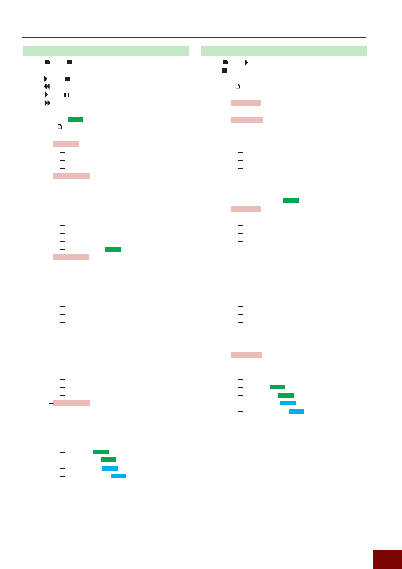
EAD50 EAD20 User Guide
73
Function Tree Diagram
[RECORDER]-Recorder
[F1] / [F1]
[+] [−] File Select
[F2] / [F2]
[F4]
[F5] / [F5]
[F6]
[F7] PlaySel
[F8] MemSel (
EAD50
only)
[F9] Save
[F3] Setting
Recorder
Volume
Repeat
Speed
Recorder Rec
Rec Gain
Rec Click
Rec Aux In
Rec USB Audio In1/2
Rec USB Audio In3/4
Rec USB Audio In5/6
Rec USB Audio In7/8
Rec Recorder Play
Rec Bluetooth (
EAD50
only)
Recorder EQ
On/Off
Low Freq
Low Gain
Low Q
Low Shape
MidLow Freq
MidLow Gain
MidLow Q
MidHigh Freq
MidHigh Gain
MidHigh Q
High Freq
High Gain
High Q
High Shape
HPF Freq
HPF Q
Recorder Out
Mode
Main Out
Phones Out
USB Audio Out 1/2
Backing Out Level
Indiv Out (
EAD50
only)
IndivOut Vol (
EAD50
only)
USB AudOut (
EAD20
only)
USB AudOut Vol (
EAD20
only)
[RECORDER]-Looper
[F1] / [F1]
[F2] / [F2] Clear
[F3] Undo / [F3] Redo
[F6] Save
[F3] Setting
Looper Vol
Volume
Looper Rec
Rec Gain
Rec Mode
Rec Beat Length
Rec Click
Rec Aux In
Rec USB Audio In 1/2
Rec USB Audio In 3/4
Rec USB Audio In 5/6
Rec USB Audio In 7/8
Rec Bluetooth (
EAD50
only)
Looper EQ
On/Off
Low Freq
Low Gain
Low Q
Low Shape
MidLow Freq
MidLow Gain
MidLow Q
MidHigh Freq
MidHigh Gain
MidHigh Q
High Freq
High Gain
High Q
High Shape
HPF Freq
HPF Q
Looper Out
Main Out
Phones Out
USB Audio Out 1/2
IndivOut (
EAD50
only)
IndivOut Vol (
EAD50
only)
USB AudOut (
EAD20
only)
USB AudOut Vol (
EAD20
only)
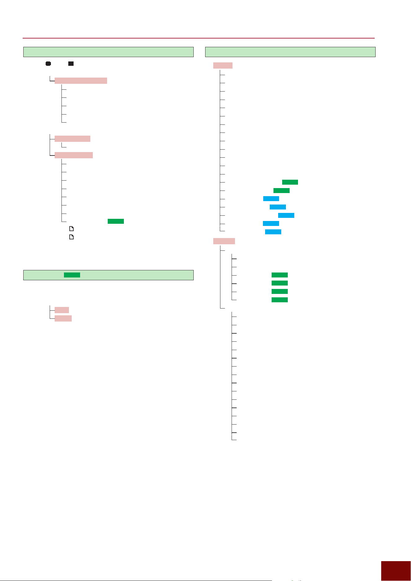
EAD50 EAD20 User Guide
74
Function Tree Diagram
[RECORDER]-Sampling
[F1] / [F1]
[F2] Edit
[F1] Play / [F1] Stop
Start Point
Loop Point
End Point
Normalize
Reverse
[F3] Setting
Sampling Vol
Volume
Sampling Rec
Rec Gain
Rec Click
Rec Aux In
Rec USB Audio In1/2
Rec USB Audio In3/4
Rec USB Audio In5/6
Rec USB Audio In7/8
Rec Bluetooth (
EAD50
only)
[F4] Load File
[F6] Save File
[F7] LoadWM
[F9] SaveWM
[LIVE SET]
(
EAD50
only)
[+] [−] Live Set
[F1] Live Set Start
[F2] Job
Sort
Clear
[F3] Setting
[MENU]
Utility
Auto Power Off
Pop-up Time
LCD Contrast
Audition Velocity
MIDI Local Control
MIDI Global Channel
MIDI Global Port
MIDI PC Tx
MIDI PC Rx
MIDI Clock Tx
MIDI Clock Rx
MIDI Start/Stop Tx
MIDI Start/Stop Rx
USB MIDI Thru MIDI (
EAD50
only)
External Memory (
EAD50
only)
Main Volume (
EAD20
only)
Phones Volume (
EAD20
only)
Mic/Trigger Volume (
EAD20
only)
Click Volume (
EAD20
only)
Audio Volume (
EAD20
only)
Output
Output Gain
Main Out
Phones Out
IndivOut1/2 (
EAD50
only)
IndivOut3/4 (
EAD50
only)
IndivOut5/6 (
EAD50
only)
IndivOut7/8 (
EAD50
only)
Phones EQ
On/Off
Type
Low Freq
Low Gain
Low Q
Low Shape
MidLow Freq
MidLow Gain
MidLow Q
MidHigh Freq
MidHigh Gain
MidHigh Q
High Freq
High Gain
High Q
High Shape
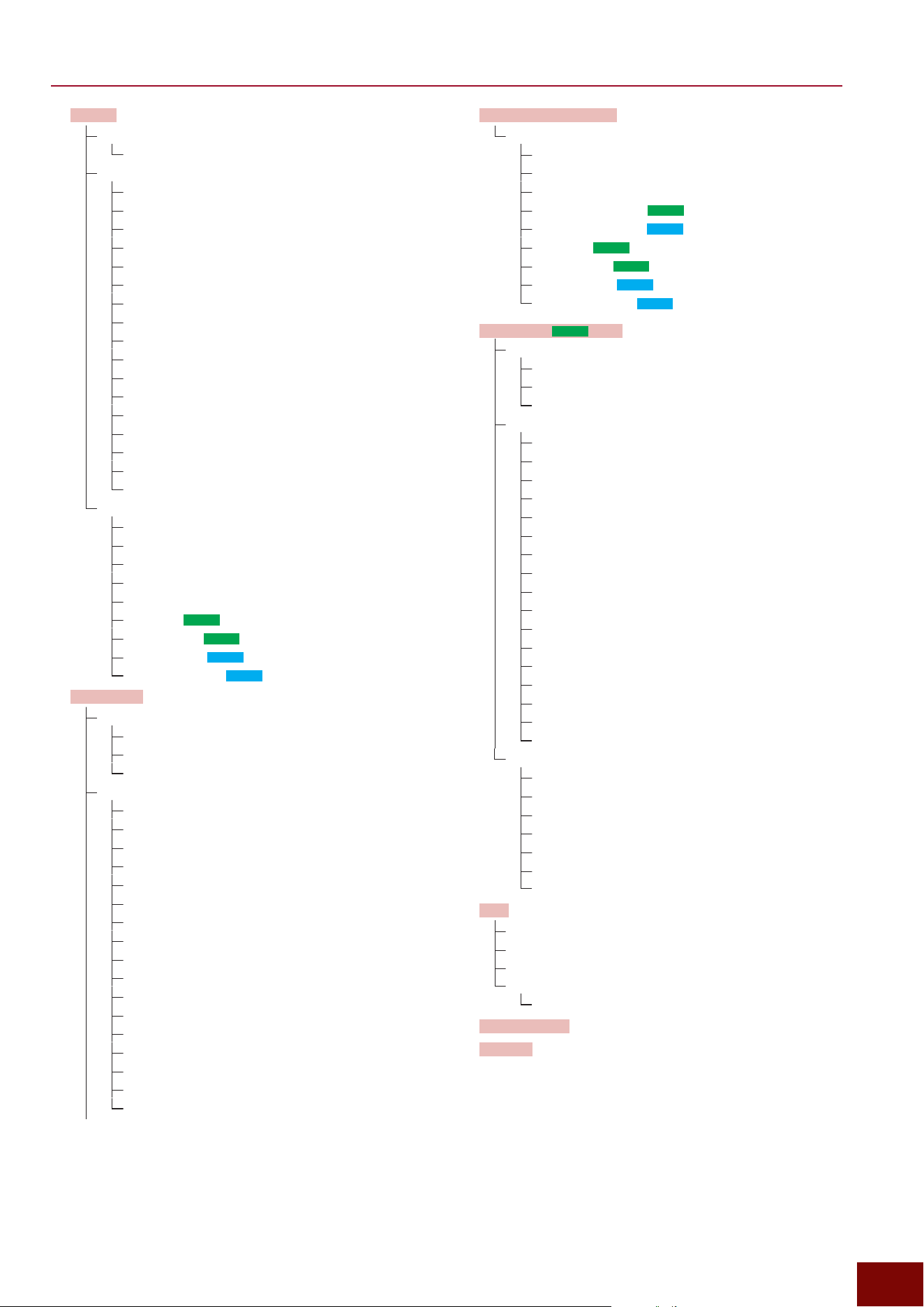
EAD50 EAD20 User Guide
75
Function Tree Diagram
Aux In
Aux In Vol
Volume
Aux In EQ
On/Off
Low Freq
Low Gain
Low Q
Low Shape
MidLow Freq
MidLow Gain
MidLow Q
MidHigh Freq
MidHigh Gain
MidHigh Q
High Freq
High Gain
High Q
High Shape
HPF Freq
HPF Q
Aux In Out
Mode
Main Out
Phones Out
USB Audio Out1/2
Backing Out Level
IndivOut (
EAD50
only)
IndivOut Vol (
EAD50
only)
USB AudOut (
EAD20
only)
USB AudOut Vol (
EAD20
only)
USB Audio
USB Audio
Mode
In Volume
Out Gain
USB Audio EQ
On/Off
Low Freq
Low Gain
Low Q
Low Shape
MidLow Freq
MidLow Gain
MidLow Q
MidHigh Freq
MidHigh Gain
MidHigh Q
High Freq
High Gain
High Q
High Shape
HPF Freq
HPF Q
USB Audio (continued)
USB AudioOut
Mode
Main Out
Phones Out
USB Audio Out1/2 (
EAD50
only)
Backing Out Level (
EAD20
only)
IndivOut (
EAD50
only)
IndivOut Vol (
EAD50
only)
USB AudOut (
EAD20
only)
USB AudOut Vol (
EAD20
only)
Bluetooth (
EAD50
only)
Bluetooth
On/Off
Volume
Pairing
Bluetooth EQ
On/Off
Low Freq
Low Gain
Low Q
Low Shape
MidLow Freq
MidLow Gain
MidLow Q
MidHigh Freq
MidHigh Gain
MidHigh Q
High Freq
High Gain
High Q
High Shape
HPF Freq
HPF Q
Bluetooth Out
Mode
Main Out
Phones Out
USB Audio Out1/2
Backing Out Level
IndivOut
IndivOut Vol
File
File All
File Scene
File Wave
ExtMem Info
Format
Factory Reset
Version
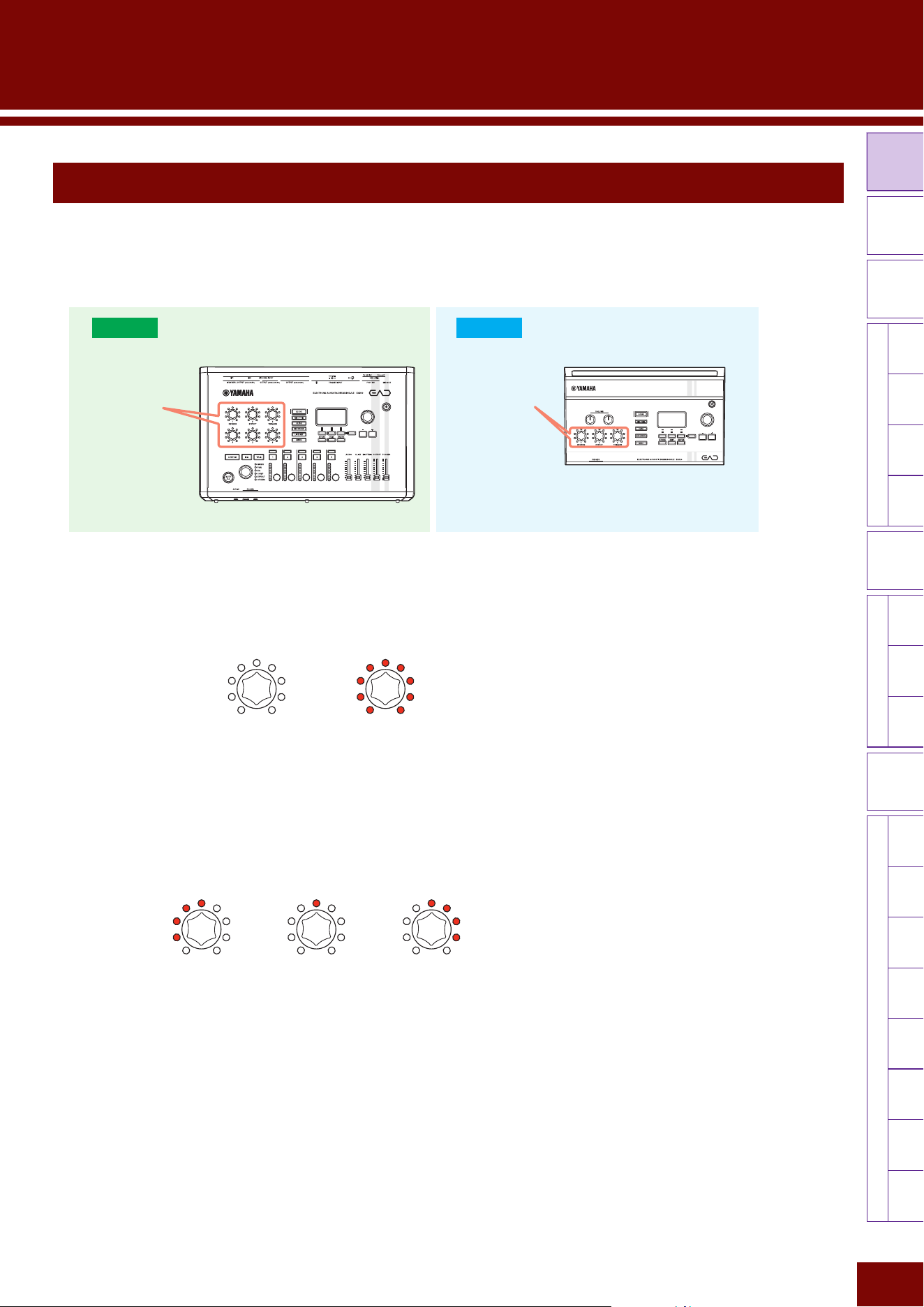
LED
Rotary
Faders
[ MIC / TRIG ] [ SCENE ][ CLICK ][ RECORDER ]
[
LIVE SET
]
[ MENU ]
MicTriggerKitEffectRecorderLooperSamplingUtilityOutputAux InUSB AudioBluetoothFileFactory
Reset
Version
Modifier
Knobs
76
EAD50 EAD20 User Guide
Modifier Knob Operations
The modifier knobs on the left side of the panel can be operated to change various tone characteristics or switch between
functions during performances. The size of the setting value can be intuitively confirmed from the illumination status of the 9
LED lamps around the knobs. Furthermore, the following types of lamp illumination are used to indicate the parameter setting
range during adjustments.
Modifier Knob Modifier Knob
EAD20
EAD50
■ Adjusting Parameters with a Setting Range of 0 – +XXX
The minimum value is indicated when the knob is fully turned to the left, whereas the maximum value is indicated when the
knob is fully turned to the right. LEDs lighting pattern differs according to the function. The illustration below shows an example
in case of the Effect depth.
■ Adjusting Parameters with a Setting Range of −XXX – 0 – +XXX
Negative setting values are indicated by unlit LEDs on the right half and increases/decreases indicated only by the left-half
LEDs.
If the setting value is zero, then only the center LED is lit.
Positive setting values are indicated by unlit LEDs on the left half and increases/decreases indicated only by right-half LEDs.
NOTE
Each LED can be illuminated at two brightness levels depending on the numeric size.
Min value Max value
Negative value Setting value of “0” Positive value
Settings in Screens (Parameters)
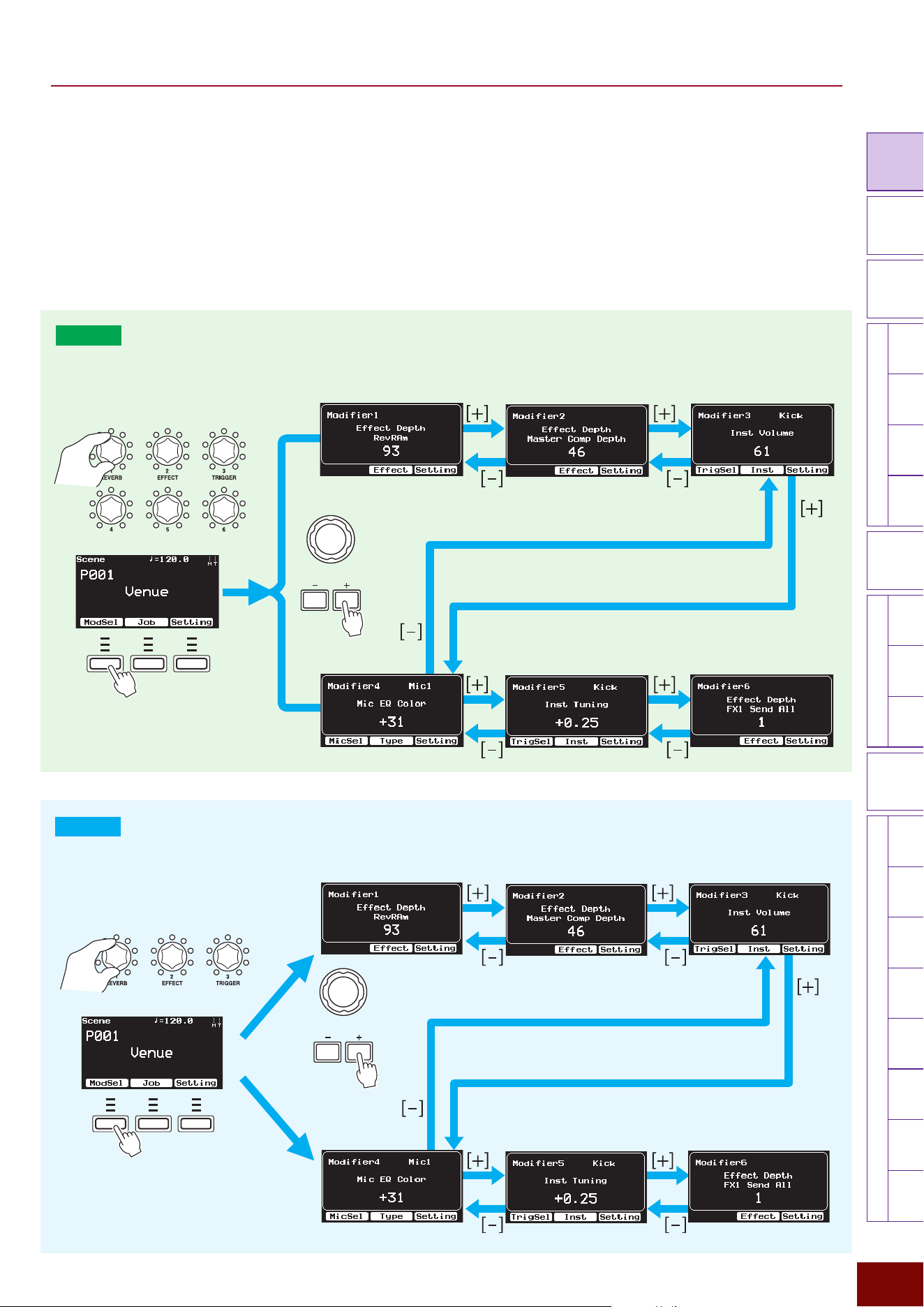
EAD50 EAD20 User Guide
77
Settings in Screens (Parameters)
LED
Rotary
Faders
[ MIC / TRIG ] [ SCENE ][ CLICK ][ RECORDER ]
[ MENU ]
MicTriggerKitEffectRecorderLooperSamplingUtilityOutputAux In
USB AudioBluetooth
FileFactory
Reset
Version
Modifier
Knobs
[
LIVE SET
]
■ Pop-Up Windows Displayed by Operating a Knob
A pop-up window with the corresponding knob (the last knob operated) for adjusting the setting parameter is displayed by
either operating the modifier knob on the left side of the control panel or by pressing the [F1] ModSel button in the Scene
screen. In addition, the [F2] and [F3] buttons displayed at the bottom of the screen also change to functions related to those
parameters.
NOTE
• The “F” in “F1 – F3” refers to “Function” and is used to name the buttons for explanatory convenience. The names are not printed on the panel.
• If “Off” is specified in the screen below, a pop-up window will not be displayed when a knob is operated.
[SCENE]
"
[F3] Setting
"
Modifier
"
Modifier Pop-up
F1 F2 F3
F1 F2 F3
For model EAD20, the three knobs can be
used as knobs 1 to 3 or as 4 to 6. The figure
shows how to switch between those display
modes.
EAD20
Modifier Knobs 1 – 3 and 4 – 6
Modifier1 – 3
Modifier4 – 6
EAD50
Modifier Knobs 1 – 6
Modifier1 – 3
Operating the knobs will cause the
corresponding display to appear on the
screen. The knobs/dials can also be used to
switch between screens.
Modifier4 – 6
EAD50 EAD20 User Guide
78
Settings in Screens (Parameters)
LED
Rotary
Faders
[ MIC / TRIG ] [ SCENE ][ CLICK ][ RECORDER ]
[ MENU ]
MicTriggerKitEffectRecorderLooperSamplingUtilityOutputAux In
USB AudioBluetooth
FileFactory
Reset
Version
Modifier
Knobs
[
LIVE SET
]
[F1] MicSel (
EAD50
only) or TrigSel
If the corresponding knob functions are microphone-related, the screen for selecting the applicable mic is displayed, but if the
corresponding knob functions are Trigger-related, then the screen for selecting the applicable Trigger is displayed.
[F2] Effect, Type, Inst, etc.
This displays the related setting screen for the corresponding knob function.
[F3] Setting
[F3] Setting"Function
This selects the function assigned to the currently selected modifier knob.
Parameter Explanation Setting Default Value
Off Disables currently selected knob.
— —
Tempo Assigns the tempo change function (Page 157).
— —
Talk On/Off Assigns function (Page 112) for switching between using the
mic jack for talking (on) or using it for musical performance
(off). If selected, turning the corresponding knob to the right
switches the Talk mode on and turning it left switches the Talk
mode off.
For model
EAD50
, when “Mic Lock” is set to “Off,” this
function is applied to the microphone selected via the [F1]
MicSel button. When set to the one other than “Off,” this
function is applied to the microphone selected here.
NOTE
For model
EAD50
, the mic jack controlled by the knob when “Mic
Lock = Off” is indicated on the screen, displayed using the [F1]
MicSel button, can be changed.
Mic Lock = Off,
Mic1–5 (
EAD50
only)
Setting value in Scene
(Modifier)
Mic EQ Color
Assigns the function (Page 112) for editing Mic EQ Color
values for microphone sound. Turning the knob to the right
increases the value to produce a brighter sound. Turning it left
decreases the value to produce a darker sound.
For model
EAD50
, when “Mic Lock” is set to “Off,” this
function is applied to the microphone selected via the [F1]
MicSel button. When set to the one other than “Off,” this
function is applied to the microphone selected here.
NOTE
The following two actions can be performed while the pop-up
window is displayed.
• For model
EAD50
, the mic jack controlled by the knob when
“Mic Lock = Off” is indicated on the screen, displayed using the
[F1] MicSel button, can be changed.
• Pressing the [F2] Type button jumps to [MIC/TRIG]
"
[F3]
Setting
"
Mic EQ
"
Type.
Mic Lock = Off,
Mic1–5 (
EAD50
only)
EAD50 EAD20 User Guide
79
Settings in Screens (Parameters)
LED
Rotary
Faders
[ MIC / TRIG ] [ SCENE ][ CLICK ][ RECORDER ]
[ MENU ]
MicTriggerKitEffectRecorderLooperSamplingUtilityOutputAux In
USB AudioBluetooth
FileFactory
Reset
Version
Modifier
Knobs
[
LIVE SET
]
Parameter Explanation Setting Default Value
Mic Tran Comp
Depth
An abbreviation for “microphone Transient Compressor
depth.”
It assigns a function (Page 114) for controlling both the
depth of the Transient Effects (attack and release) and the
Compressor applied to microphone sounds. Turning the knob
to the right produces a deeper sound. Turning it left produces
a shallower sound.
For model
EAD50
, when “Mic Lock” is set to “Off,” this
function is applied to the microphone selected via the [F1]
MicSel button. When set to the one other than “Off,” this
function is applied to the microphone selected here.
NOTE
The following two actions can be performed while the pop-up
window is displayed.
• For model
EAD50
, the mic jack controlled by the knob when
“Mic Lock = Off” is indicated on the screen, displayed using the
[F1] MicSel button, can be changed.
• Pressing the [F2] Type button jumps to [MIC/TRIG]
"
[F3] Setting
"
Mic TransComp
"
Type.
Mic Lock = Off,
Mic1–5 (
EAD50
only)
Setting value in Scene
(Modifier)
Mic Tran Attack An abbreviation for “Microphone Transient Attack.”
Assigns a function (Page 114) for controlling the Transient
effect attack strength applied to mic sounds. Turning the knob
to the right makes the attack stronger, whereas turning it left
makes the attack weaker.
For model
EAD50
, when “Mic Lock” is set to “Off,” this
function is applied to the microphone selected via the [F1]
MicSel button. When set to the one other than “Off,” this
function is applied to the microphone selected here.
NOTE
The following two actions can be performed while the pop-up
window is displayed.
• On the screen displayed using the [F1] MicSel button, mic jacks
controlled by the knob can be changed when Mic Lock = Off.
• Pressing the [F2] Sens button jumps to [MIC/TRIG]
"
[F3]
Setting
"
Mic TransComp
"
Tran Sensitivity.
Mic Lock = Off,
Mic1–5 (
EAD50
only)
Mic Tran Release An abbreviation for “Microphone Transient Release.”
Assigns a function (Page 114) for controlling the sense of
Transient release effect applied to mic sounds. Turning the
knob to the right increases the lingering, whereas turning it
left decreases the lingering.
For model
EAD50
, when “Mic Lock” is set to “Off,” this
function is applied to the microphone selected via the [F1]
MicSel button. When set to the one other than “Off,” this
function is applied to the microphone selected here.
NOTE
The following two actions can be performed while the pop-up
window is displayed.
• For model
EAD50
, the mic jack controlled by the knob when
“Mic Lock = Off” is indicated on the screen, displayed using the
[F1] MicSel button, can be changed.
• Pressing the [F2] Sens button jumps to [MIC/TRIG]
"
[F3]
Setting
"
Mic TransComp
"
Tran Sensitivity.
Mic Lock = Off,
Mic1–5 (
EAD50
only)
EAD50 EAD20 User Guide
80
Settings in Screens (Parameters)
LED
Rotary
Faders
[ MIC / TRIG ] [ SCENE ][ CLICK ][ RECORDER ]
[ MENU ]
MicTriggerKitEffectRecorderLooperSamplingUtilityOutputAux In
USB AudioBluetooth
FileFactory
Reset
Version
Modifier
Knobs
[
LIVE SET
]
Parameter Explanation Setting Default Value
Xstick On/Off Assigns the Xstick on/off setting function (Page 120) to
a specific Trigger Input. The on setting is enabled only for
Trigger Inputs connected to multi-piezo pads.
When “Trigger Lock” is set to “Off,” this function is applied to
the Trigger Input selected via the [F1] TrigSel button. When
set to the one other than “Off,” this function is applied to the
Trigger Input selected here.
NOTE
The following two actions can be performed while the pop-up
window is displayed.
• This enables using the [F1] TrigSel button to change the Trigger
Input controlled by the knob when Trigger Lock = Off.
• Pressing the [F2] Adjust button jumps to [MIC/TRIG]
"
[F3]
Setting
"
Trigger
"
Trig In
"
Pad
"
Xstick Adjust.
NOTE
The setting is only enabled when the selected Trigger Input is Kick,
Snare, or Trig3–5.
Trigger Lock
•
EAD50
:
Off, Kick, Snare,
Trig3–10,
Foot1–2,
Trig11–22
•
EAD20
:
Off, Kick, Snare,
Trig3–9, Foot
Setting value in Scene
(Modifier)
Inst Number Assigns the function (Page 126) for selecting Insts for
currently selected Trigger Inputs. It allows selecting Insts
within the currently selected category.
When “Trigger Lock” is set to “Off,” this function is applied to
the Trigger Input selected via the [F1] TrigSel button. When
set to the one other than “Off,” this function is applied to the
Trigger Input selected here.
NOTE
The following two actions can be performed while the pop-up
window is displayed.
• This enables using the [F1] TrigSel button to change the Trigger
Input controlled by the knob when Trigger Lock = Off.
• Pressing the [F2] Inst button jumps to [MIC/TRIG]
"
[F3] Setting
"
Kit
"
Inst
"
Inst
"
Category.
Trigger Lock
•
EAD50
:
Off, Kick, Snare,
Trig3–10,
Foot1–2,
Trig11–22
•
EAD20
:
Off, Kick, Snare,
Trig3–9, Foot
Inst Volume Assigns the function (Page 127) for adjusting the Inst volume
for currently selected Trigger Inputs.
When “Trigger Lock” is set to “Off,” this function is applied to
the Trigger Input selected via the [F1] TrigSel button. When
set to the one other than “Off,” this function is applied to the
Trigger Input selected here.
NOTE
The following two actions can be performed while the pop-up
window is displayed.
• This enables using the [F1] TrigSel button to change the Trigger
Input controlled by the knob when Trigger Lock = Off.
• Pressing the [F2] Inst button jumps to [MIC/TRIG]
"
[F3] Setting
"
Kit
"
Inst
"
Inst
"
Category.
Trigger Lock
•
EAD50
:
Off, Kick, Snare,
Trig3–10,
Foot1–2,
Trig11–22
•
EAD20
:
Off, Kick, Snare,
Trig3–9, Foot
EAD50 EAD20 User Guide
81
Settings in Screens (Parameters)
LED
Rotary
Faders
[ MIC / TRIG ] [ SCENE ][ CLICK ][ RECORDER ]
[ MENU ]
MicTriggerKitEffectRecorderLooperSamplingUtilityOutputAux In
USB AudioBluetooth
FileFactory
Reset
Version
Modifier
Knobs
[
LIVE SET
]
Parameter Explanation Setting Default Value
Inst Pan
Assigns the function (Page 127) for adjusting the stereo position
of currently selected Trigger Input Insts.
When “Trigger Lock” is set to “Off,” this function is applied to
the Trigger Input selected via the [F1] TrigSel button. When
set to the one other than “Off,” this function is applied to the
Trigger Input selected here.
NOTE
The following two actions can be performed while the pop-up
window is displayed.
• This enables using the [F1] TrigSel button to change the Trigger
Input controlled by the knob when Trigger Lock = Off.
• Pressing the [F2] Inst button jumps to [MIC/TRIG]
"
[F3] Setting
"
Kit
"
Inst
"
Inst
"
Category.
Trigger Lock
•
EAD50
:
Off, Kick, Snare,
Trig3–10,
Foot1–2,
Trig11–22
•
EAD20
:
Off, Kick, Snare,
Trig3–9, Foot
Setting value in Scene
(Modifier)
Inst Tuning/Size This assigns the function
(Page 127)
for tuning or setting
the size (such as for cymbals) of Insts for currently selected
Trigger Inputs. The type of function depends on the Inst.
When “Trigger Lock” is set to “Off,” this function is applied to
the Trigger Input selected via the [F1] TrigSel button. When
set to the one other than “Off,” this function is applied to the
Trigger Input selected here.
NOTE
The following two actions can be performed while the pop-up
window is displayed.
• This enables using the [F1] TrigSel button to change the Trigger
Input controlled by the knob when Trigger Lock = Off.
• Pressing the [F2] Inst button jumps to [MIC/TRIG]
"
[F3] Setting
"
Kit
"
Inst
"
Inst
"
Category.
Trigger Lock
•
EAD50
:
Off, Kick, Snare,
Trig3–10,
Foot1–2,
Trig11–22
•
EAD20
:
Off, Kick, Snare,
Trig3–9, Foot
Inst Attack
Assigns the function (Page 127) for setting the attack effect of
Insts for currently selected Trigger Inputs.
When “Trigger Lock” is set to “Off,” this function is applied to
the Trigger Input selected via the [F1] TrigSel button. When
set to the one other than “Off,” this function is applied to the
Trigger Input selected here.
NOTE
The following two actions can be performed while the pop-up
window is displayed.
• This enables using the [F1] TrigSel button to change the Trigger
Input controlled by the knob when Trigger Lock = Off.
• Pressing the [F2] Inst button jumps to [MIC/TRIG]
"
[F3] Setting
"
Kit
"
Inst
"
Inst
"
Category.
Trigger Lock
•
EAD50
:
Off, Kick, Snare,
Trig3–10,
Foot1–2,
Trig11–22
•
EAD20
:
Off, Kick, Snare,
Trig3–9, Foot
EAD50 EAD20 User Guide
82
Settings in Screens (Parameters)
LED
Rotary
Faders
[ MIC / TRIG ] [ SCENE ][ CLICK ][ RECORDER ]
[ MENU ]
MicTriggerKitEffectRecorderLooperSamplingUtilityOutputAux In
USB AudioBluetooth
FileFactory
Reset
Version
Modifier
Knobs
[
LIVE SET
]
Parameter Explanation Setting Default Value
Inst Muffling/
Sustain/Decay
Assigns the function
(Page 127)
for adjusting the muffling,
sustain, or decay level of Insts for currently selected Trigger
Inputs. The type of function depends on the Inst.
When “Trigger Lock” is set to “Off,” this function is applied to
the Trigger Input selected via the [F1] TrigSel button. When
set to the one other than “Off,” this function is applied to the
Trigger Input selected here.
NOTE
The following two actions can be performed while the pop-up
window is displayed.
• This enables using the [F1] TrigSel button to change the Trigger
Input controlled by the knob when Trigger Lock = Off.
• Pressing the [F2] Inst button jumps to [MIC/TRIG]
"
[F3] Setting
"
Kit
"
Inst
"
Inst
"
Category.
Trigger Lock
•
EAD50
:
Off, Kick, Snare,
Trig3–10,
Foot1–2,
Trig11–22
•
EAD20
:
Off, Kick, Snare,
Trig3–9, Foot
Setting value in Scene
(Modifier)
Inst EQ Color
Assigns the
(Page 128)
function for adjusting the EQ color
(sound brightness) level of Insts for currently selected Trigger
Inputs.
When “Trigger Lock” is set to “Off,” this function is applied to
the Trigger Input selected via the [F1] TrigSel button. When
set to the one other than “Off,” this function is applied to the
Trigger Input selected here.
NOTE
The following two actions can be performed while the pop-up
window is displayed.
• This enables using the [F1] TrigSel button to change the Trigger
Input controlled by the knob when Trigger Lock = Off.
• Pressing the [F2] InstEQ button jumps to [MIC/TRIG]
"
[F3]
Setting
"
Kit
"
Inst
"
Inst EQ
"
Type.
Trigger Lock
•
EAD50
:
Off, Kick, Snare,
Trig3–10,
Foot1–2,
Trig11–22
•
EAD20
:
Off, Kick, Snare,
Trig3–9, Foot
Inst Tran Comp
Depth
An abbreviation for “Instrument Transient Compressor Depth.”
Assigns the function
(Page 129)
for adjusting the Transient
Compressor effect level applied to Insts for currently selected
Trigger Inputs.
When “Trigger Lock” is set to “Off,” this function is applied to
the Trigger Input selected via the [F1] TrigSel button. When
set to the one other than “Off,” this function is applied to the
Trigger Input selected here.
NOTE
The following two actions can be performed while the pop-up
window is displayed.
• This enables using the [F1] TrigSel button to change the Trigger
Input controlled by the knob when Trigger Lock = Off.
• Pressing the [F2] Type button jumps to [MIC/TRIG]
"
[F3]
Setting
"
Kit
"
Inst
"
Inst
"
InstTranComp
"
Type.
Trigger Lock
•
EAD50
:
Off, Kick, Snare,
Trig3–10,
Foot1–2,
Trig11–22
•
EAD20
:
Off, Kick, Snare,
Trig3–9, Foot
EAD50 EAD20 User Guide
83
Settings in Screens (Parameters)
LED
Rotary
Faders
[ MIC / TRIG ] [ SCENE ][ CLICK ][ RECORDER ]
[ MENU ]
MicTriggerKitEffectRecorderLooperSamplingUtilityOutputAux In
USB AudioBluetooth
FileFactory
Reset
Version
Modifier
Knobs
[
LIVE SET
]
Parameter Explanation Setting Default Value
Inst Tran Attack An abbreviation for “Instrument Transient Attack.”
Assigns the function (Page 129) for adjusting the Transient
attack effect of Insts for currently selected Trigger Inputs.
When “Trigger Lock” is set to “Off,” this function is applied to
the Trigger Input selected via the [F1] TrigSel button. When
set to the one other than “Off,” this function is applied to the
Trigger Input selected here.
NOTE
The following two actions can be performed while the pop-up
window is displayed.
• This enables using the [F1] TrigSel button to change the Trigger
Input controlled by the knob when Trigger Lock = Off.
• Pressing the [F2] Sens button jumps to [MIC/TRIG]
"
[F3]
Setting
"
Kit
"
Inst
"
InstTransComp
"
Tran Sensitivity.
Trigger Lock
•
EAD50
:
Off, Kick, Snare,
Trig3–10,
Foot1–2,
Trig11–22
•
EAD20
:
Off, Kick, Snare,
Trig3–9, Foot
Setting value in Scene
(Modifier)
Inst Tran Release An abbreviation for “Instrument Transient Release.”
Assigns the function (Page 129) for adjusting the Transient
release effect level of Insts for currently selected Trigger
Inputs.
When “Trigger Lock” is set to “Off,” this function is applied to
the Trigger Input selected via the [F1] TrigSel button. When
set to the one other than “Off,” this function is applied to the
Trigger Input selected here.
NOTE
The following two actions can be performed while the pop-up
window is displayed.
• This enables using the [F1] TrigSel button to change the Trigger
Input controlled by the knob when Trigger Lock = Off.
• Pressing the [F2] Sens button jumps to [MIC/TRIG]
"
[F3]
Setting
"
Kit
"
Inst
"
InstTransComp
"
Tran Sensitivity.
Trigger Lock
•
EAD50
:
Off, Kick, Snare,
Trig3–10,
Foot1–2,
Trig11–22
•
EAD20
:
Off, Kick, Snare,
Trig3–9, Foot
Voice Volume
Assigns the function
(Page 134)
for adjusting the volume
level of Voices included in Insts for currently selected Trigger
Inputs. Settings at the bottom of the screen individually specify
whether volume adjustments are applied (with check mark) or
not applied (without check mark) to each layer.
NOTE
The following two actions can be performed while the pop-up
window is displayed.
• The Trigger Inputs controlled by the knob can be changed using
the [F1] TrigSel button.
• Pressing the [F2] Voice button jumps to [MIC/TRIG]
"
[F3]
Setting
"
Kit
"
Voice
"
Voice
"
Category.
For each parameter:
• With check mark
• Without check mark
EAD50 EAD20 User Guide
84
Settings in Screens (Parameters)
LED
Rotary
Faders
[ MIC / TRIG ] [ SCENE ][ CLICK ][ RECORDER ]
[ MENU ]
MicTriggerKitEffectRecorderLooperSamplingUtilityOutputAux In
USB AudioBluetooth
FileFactory
Reset
Version
Modifier
Knobs
[
LIVE SET
]
Parameter Explanation Setting Default Value
Effect Depth
This assigns the function for adjusting the depth of Effects.
Settings at the lower half of the screen can individually specify
whether depth adjustments are applied (checkbox selected)
or not applied (checkbox unselected) to each block included
in Effects.
• Reverb Send All (Page 147)
• Real Ambi Depth All (Page 149)
• FX1 Send All (Page 149)
• FX2 Send All (Page 150)
• Dry Level All (Page 151)
• Master FX Depth (Page 153)
• Master Comp Depth (Page 154)
NOTE
While the pop-up window is displayed, pressing the [F2] Effect
button jumps to [MIC/TRIG]
"
[F3] Setting
"
Effect.
— Setting value in Scene
(Modifier)
Reverb Param A
This adjusts the parameter A, B, and C values for the currently
selected Reverb type. For information about parameters A, B,
and C, refer to “the Effect Type List” in the Data List.
NOTE
While the pop-up window is displayed, pressing the [F2] Type button
jumps to [MIC/TRIG]
"
[F3] Setting
"
Effect
"
Reverb
"
Type.
— —
Reverb Param B
Reverb Param C
FX1 Param A
This adjusts the parameter A, B, and C values for the currently
selected FX1 type. For information about parameters A, B, and
C, refer to “the Effect Type List” in the Data List.
NOTE
While the pop-up window is displayed, pressing the [F2] Type
button jumps to [MIC/TRIG]
"
[F3] Setting
"
Effect
"
FX1
"
Type.
— —
FX1 Param B
FX1 Param C
FX2 Param A
This adjusts the parameter A, B, and C values for the currently
selected FX2 type. For information about parameters A, B, and
C, refer to “the Effect Type List” in the Data List.
NOTE
While the pop-up window is displayed, pressing the [F2] Type
button jumps to [MIC/TRIG]
"
[F3] Setting
"
Effect
"
FX2
"
Type.
— —
FX2 Param B
FX2 Param C
EAD50 EAD20 User Guide
85
Settings in Screens (Parameters)
LED
Rotary
Faders
[ MIC / TRIG ] [ SCENE ][ CLICK ][ RECORDER ]
[ MENU ]
MicTriggerKitEffectRecorderLooperSamplingUtilityOutputAux In
USB AudioBluetooth
FileFactory
Reset
Version
Modifier
Knobs
[
LIVE SET
]
Parameter Explanation Setting Default Value
Ins1 Mic Depth
Assigns the function (Page 152) for adjusting the Depth of
Insertion Effect 1 for currently selected mic sounds.
For model
EAD50
,
when “Mic Lock” is set to “Off,” this function
is applied to the microphone selected using the [F1] MicSel
button. When set to the one other than “Off,” this function is
applied to the microphone selected here.
NOTE
The following two actions can be performed while the pop-up
window is displayed.
• For model
EAD50
, the mic jack controlled by the knob when “Mic
Lock = Off” is indicated on the screen, displayed using the [F1]
MicSel button, can be changed.
• Pressing the [F2] Type button jumps to [MIC/TRIG]
"
[F3]
Setting
"
Effect
"
Ins1 Mic
"
Type.
Mic Lock = Off,
Mic1–5
Setting value in Scene
(Modifier)
Ins1 Mic Param A
Assigns the function (Page 152) for adjusting Insertion Effect
1 type parameter A, B, and C values for currently selected mic
sounds. For information about parameters A, B, and C, refer to
“the Effect Type List” in the Data List.
For model
EAD50
, when “Mic Lock” is set to “Off,” this
function is applied to the microphone selected via the [F1]
MicSel button. When set to the one other than “Off,” this
function is applied to the microphone selected here.
NOTE
The following two actions can be performed while the pop-up
window is displayed.
• For model
EAD50
, the mic jack controlled by the knob when
“Mic Lock = Off” is indicated on the screen, displayed using the
[F1] MicSel button, can be changed.
• Pressing the [F2] Type button jumps to [MIC/TRIG]
"
[F3]
Setting
"
Effect
"
Ins1 Mic
"
Type.
Mic Lock = Off,
Mic1–5
Ins1 Mic Param B
Ins1 Mic Param C
Ins2 Mic Depth
Assigns the function (Page 152) for adjusting the depth level
of Insertion Effect 2 type settings for currently selected mic
sounds.
For model
EAD50
, when “Mic Lock” is set to “Off,” this function
is applied to the microphone selected via the [F1] MicSel
button. When set to the one other than “Off,” this function is
applied to the microphone selected here.
NOTE
The following two actions can be performed while the pop-up
window is displayed.
• For model
EAD50
, the mic jack controlled by the knob when
“Mic Lock = Off” is indicated on the screen, displayed using the
[F1] MicSel button, can be changed.
• Pressing the [F2] Type button jumps to [MIC/TRIG]
"
[F3]
Setting
"
Effect
"
Ins2 Mic
"
Type.
Mic Lock = Off,
Mic1–5
EAD50 EAD20 User Guide
86
Settings in Screens (Parameters)
LED
Rotary
Faders
[ MIC / TRIG ] [ SCENE ][ CLICK ][ RECORDER ]
[ MENU ]
MicTriggerKitEffectRecorderLooperSamplingUtilityOutputAux In
USB AudioBluetooth
FileFactory
Reset
Version
Modifier
Knobs
[
LIVE SET
]
Parameter Explanation Setting Default Value
Ins2 Mic Param A
Assigns the function (Page 152) for adjusting Insertion Effect
2 type parameter A, B, and C values for currently selected mic
sounds. For information about parameters A, B, and C, refer to
“the Effect Type List” in the Data List.
For model
EAD50
, when “Mic Lock” is set to “Off,” this function
is applied to the microphone selected via the [F1] MicSel
button. When set to the one other than “Off,” this function is
applied to the microphone selected here.
NOTE
The following two actions can be performed while the pop-up
window is displayed.
• On the screen displayed using the [F1] MicSel button, mic jacks
controlled by the knob can be changed when Mic Lock = Off.
• Pressing the [F2] Type button jumps to [MIC/TRIG]
"
[F3]
Setting
"
Effect
"
Ins2 Mic
"
Type.
Mic Lock = Off,
Mic1–5
Setting value in Scene
(Modifier)
Ins2 Mic Param B
Ins2 Mic Param C
Ins Trig Depth
Assigns the function (Page 153) for adjusting the depth of
Insertion Effect type settings for currently selected Trigger
sounds.
When “Trigger Lock” is set to “Off,” this function is applied to
currently selected Trigger Inputs. When set to the one other
than “Off,” this function is applied to the Trigger Input selected
here.
NOTE
The following two actions can be performed while the pop-up
window is displayed.
• For model
EAD50
, the [F1] TrigSel button can be used to
change the Trigger Input controlled by the knob when Trigger
Lock = Off.
• Pressing the [F2] Type button jumps to [MIC/TRIG]
"
[F3]
Setting
"
Effect
"
Ins Trig
"
Type.
Trigger Lock = Off,
Kick, Snare,
Trig3–10,
Foot1–2,
Trig11–22 (no effect
on 18 to 22)
Ins Trig Param A
This assigns the function (Page 153) for adjusting parameter
A, B, and C values for Insertion Effect types for currently
selected Trigger sounds.
For information about parameters A, B, and C, refer to the
“Effect
Type
List” in the Data List.
When “Trigger Lock” is set to “Off,” this function is applied to
currently selected Trigger Inputs. When set to the one other
than “Off,” this function is applied to the Trigger Input selected
here.
NOTE
The following two actions can be performed while the pop-up
window is displayed.
• This enables using the [F1] TrigSel button to change the Trigger
Input controlled by the knob when Trigger Lock = Off.
• Pressing the [F2] Type button jumps to [MIC/TRIG]
"
[F3]
Setting
"
Effect
"
Ins Trig
"
Type.
Trigger Lock = Off,
Kick, Snare,
Trig3–10,
Foot1–2,
Trig11–22 (no effect
on 18 to 22)
Ins Trig Param B
Ins Trig Param C
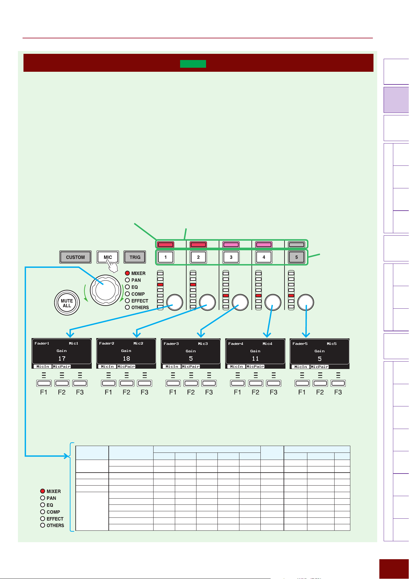
EAD50 EAD20 User Guide
87
Settings in Screens (Parameters)
Modifier
Knobs
LED
Rotary
Faders
[ MIC / TRIG ] [ SCENE ][ CLICK ][ RECORDER ]
[ MENU ]
MicTriggerKitEffectRecorderLooperSamplingUtilityOutputAux In
USB AudioBluetooth
FileFactory
Reset
Version
[
LIVE SET
]
Operating LED Rotary Faders (
EAD50
only)
A variety of sounds can be controlled during performances, by operating the five LED rotary fader knobs located at the bottom
center area of the panel. The size of setting values can be intuitively determined from the position of LED lamps lit next to the
faders.
NOTE
Each LED can be illuminated at two brightness levels depending on the numeric size.
■ Controlling Mic Input Sounds
While the [MIC] button is lit, inputs from the mic input jacks can be controlled by operating the five faders located at the bottom
center of the control panel.
If mic 1 and 2 are paired in the Mic Pairing screen, operating the fader for either mic 1 or 2 will change the setting values for
both mics. The same applies if mics 3 and 4 are paired. When a fader is operated, a pop-up window appears, where control
parameters and current numeric values can be confirmed.
When the knob
is turned, the
corresponding lamp
changes to being lit.
This selects the function to
be controlled by this knob.
NOTE
The “F” in “F1 – F3” refers to “Function” and is used to name the buttons
for explanatory convenience. The names are not printed on the panel.
NOTE
If “Off” is specified in the screen below, a pop-up window will not be
displayed when a knob is operated.
[SCENE]
"
[F3] Setting
"
Fader
"
Fader Pop-up
z
Channel On/Off
Buttons
Turns corresponding mic
channels on (lit) or off (unlit).
If channels 1 and 2 are
paired in the Mic Pairing
screen*, operating the
button for either channel 1
or 2 will turn both channels
on or off. The same applies
if mics 3 and 4 are paired.
* Mic Pairing Screen
[MIC/TRIG]
"
[F3] Setting
"
Mic
"
Mic Pairing
z
Channel Lamps
These lamps function to indicate the mic pairing status.
If channels 1 and 2 are paired in the Mic Pairing screen, then lamps 1 and 2
are illuminated a dark red color, whereas if 3 and 4 are paired, then lamps 3
and 4 are illuminated a light red color. However, lamp 5 always remains unlit
(actually, only slightly illuminated).
z
Peak Indicators
When the [MIC] button is lit, these also function as peak
indicators. If the mic input sound reaches the peak level, the
lamp for the corresponding channel will flash red. The optimal
status is when the indicators flash occasionally when the overall
drum set is hit during drum performances.
Function
Category
Function
[MIC/LINE INPUT] Jack for Each LED Rotary Fader
Vertical
LEDs
Buttons Along Screen Bottom
1 2 3 4 5 F1 F2 F3
MIXER
Gain Mic1 Mic2 Mic3 Mic4 Mic5 - MicIn MicPair -
Volume Mic1 Mic2 Mic3 Mic4 Mic5 - MicIn MicPair -
PA N
Pan Mic1 Mic2 Mic3 Mic4 Mic5 Center 0 MicIn MicPair -
EQ
EQ Color Mic1 Mic2 Mic3 Mic4 Mic5 Center 0 Type - -
COMP
Tran Comp Depth Mic1 Mic2 Mic3 Mic4 Mic5 - Type - -
EFFECT
Reverb Send Mic1 Mic2 Mic3 Mic4 Mic5 - Type - -
FX1 Send Mic1 Mic2 Mic3 Mic4 Mic5 - Type - -
FX2 Send Mic1 Mic2 Mic3 Mic4 Mic5 - Type - -
Dry Level Mic1 Mic2 Mic3 Mic4 Mic5 - Dry - -
Ins1 Depth Mic1 Mic2 Mic3 Mic4 Mic5 - Type - -
Ins2 Depth Mic1 Mic2 Mic3 Mic4 Mic5 - Type - -
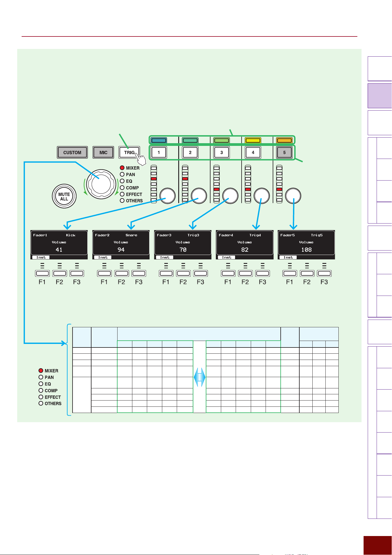
EAD50 EAD20 User Guide
88
Settings in Screens (Parameters)
Modifier
Knobs
LED
Rotary
Faders
[ MIC / TRIG ] [ SCENE ][ CLICK ][ RECORDER ]
[ MENU ]
MicTriggerKitEffectRecorderLooperSamplingUtilityOutputAux In
USB AudioBluetooth
FileFactory
Reset
Version
[
LIVE SET
]
■ Controlling Trigger Sounds
While the [TRIG] lamp is lit, inputs from the Trigger Input jacks can be controlled by operating the five faders located at the
bottom center of the control panel.
When a fader is operated, a pop-up window appears, where control parameters and current
numeric values can be confirmed.
When the knob
is turned, the
corresponding lamp
changes to being lit.
This selects the function to
be controlled by this knob.
NOTE
The “F” in “F1 – F3” refers to “Function” and is used to name the buttons
for explanatory convenience. The names are not printed on the panel.
z
Channel On/Off Buttons
Turns respective Trigger
sounds controlled by the fader
on (lit) or off (unlit).
z
Channel Lamps
Indicates the pairing status (1 and 6, 2 and 7, 3 and 8, 4 and 9, or 5 and 10) of Trigger
signals controlled by each fader. The lamps are color-coded with dark blue for Separate or
color variations from bright blue to various yellows for Pairings of 1 to 5.
Function
Category
Function
Trigger Input for Each LED Rotary Fader
Pressing [TRIG] Changes Both
Vertical
LEDs
Buttons Along
Screen Bottom
1 2 3 4 5 6 7 8 9 10 F1 F2 F3
MIXER
Volume Kick Snare Trig3 Trig4 Trig5 Trig6 Trig7 Trig8 Trig9 Trig10 - Inst - -
PA N
Pan Kick Snare Trig3 Trig4 Trig5 Trig6 Trig7 Trig8 Trig9 Trig10 Center 0 Inst - -
EQ
EQ Color Kick Snare Trig3 Trig4 Trig5 Trig6 Trig7 Trig8 Trig9 Trig10 Center 0 Type - -
COMP Tran Comp
Depth
Kick Snare Trig3 Trig4 Trig5 Trig6 Trig7 Trig8 Trig9 Trig10 - Type - -
EFFECT Reverb Real
Ambi Send
Kick Snare Trig3 Trig4 Trig5 Trig6 Trig7 Trig8 Trig9 Trig10 - Type - -
FX1 Send Kick Snare Trig3 Trig4 Trig5 Trig6 Trig7 Trig8 Trig9 Trig10 - Type - -
FX2 Send Kick Snare Trig3 Trig4 Trig5 Trig6 Trig7 Trig8 Trig9 Trig10 - Type - -
Dry Level Kick Snare Trig3 Trig4 Trig5 Trig6 Trig7 Trig8 Trig9 Trig10 - Dry - -
Ins Depth Kick Snare Trig3 Trig4 Trig5 Trig6 Trig7 Trig8 Trig9 Trig10 - Type - -
Pressing this when lit changes the Trigger Input signals controlled
by the 5 faders to Kick, Snare, Trig3 – Trig5, and Trig6 – Trig10.
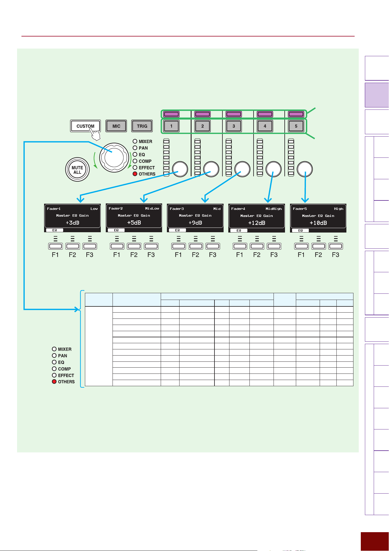
EAD50 EAD20 User Guide
89
Settings in Screens (Parameters)
Modifier
Knobs
LED
Rotary
Faders
[ MIC / TRIG ] [ SCENE ][ CLICK ][ RECORDER ]
[ MENU ]
MicTriggerKitEffectRecorderLooperSamplingUtilityOutputAux In
USB AudioBluetooth
FileFactory
Reset
Version
[
LIVE SET
]
■ Other Cases
While the [CUSTOM] lamp (or [OTHERS] lamp) is lit, EQ and Click can be controlled by operating the five faders located at the
bottom of the control panel. When a fader is operated, a pop-up window appears, where currently controlled parameters and
current numeric values can be confirmed.
Turning the knob changes the
controlled function, but the
[OTHERS] lamp remains lit.
This selects the function to be
controlled by this knob.
NOTE
The “F” in “F1 – F3” refers to “Function” and is used to name the buttons for explanatory convenience.
The names are not printed on the panel.
Remain unlit.
Remain lit with a bright
purple. However, it
is unlit if no function
is assigned (actually
faintly lit).
Function
Category
Function
Setting Parameter for Each LED Rotary Fader
Vertical
LEDs
Buttons Along Screen Bottom
1 2 3 4 5 F1 F2 F3
OTHERS
Master EQ Gain Low MidLow Mid MidHigh High Center 0
EQ
- -
Phones EQ Gain Low MidLow --- MidHigh High Center 0
EQ
- -
Playback1 EQ Gain Low MidLow --- MidHigh High Center 0
EQ*
- -
Playback2 EQ Gain Low MidLow --- MidHigh High Center 0
EQ**
- -
Looper EQ Gain Low MidLow --- MidHigh High Center 0
EQ***
- -
Aux In EQ Gain Low MidLow --- MidHigh High Center 0
EQ
- -
USB Aud In1/2 EQ Gain Low MidLow --- MidHigh High Center 0
EQ
- -
USB Aud In3/4 EQ Gain Low MidLow --- MidHigh High Center 0
EQ
- -
USB Aud In5/6 EQ Gain Low MidLow --- MidHigh High Center 0
EQ
- -
USB Aud In7/8 EQ Gain Low MidLow --- MidHigh High Center 0
EQ
- -
Bluetooth EQ Gain Low MidLow --- MidHigh High Center 0
EQ
Click EQ Gain Low MidLow --- MidHigh High Center 0
EQ
- -
Click Volume Accent 4th (Dotted4th) 8th 16th 8thTriplet -
Click
- -
* Only displayed if Recorder was the last status in
the Recorder screen and also [F7] PlaySel = 1,
regardless of the current mode.
** Only displayed if Recorder was the last status in
the Recorder screen and also [F7] PlaySel = 2,
regardless of the current mode.
*** Only displayed if Looper was the last status in the
Recorder screen, regardless of the current mode.
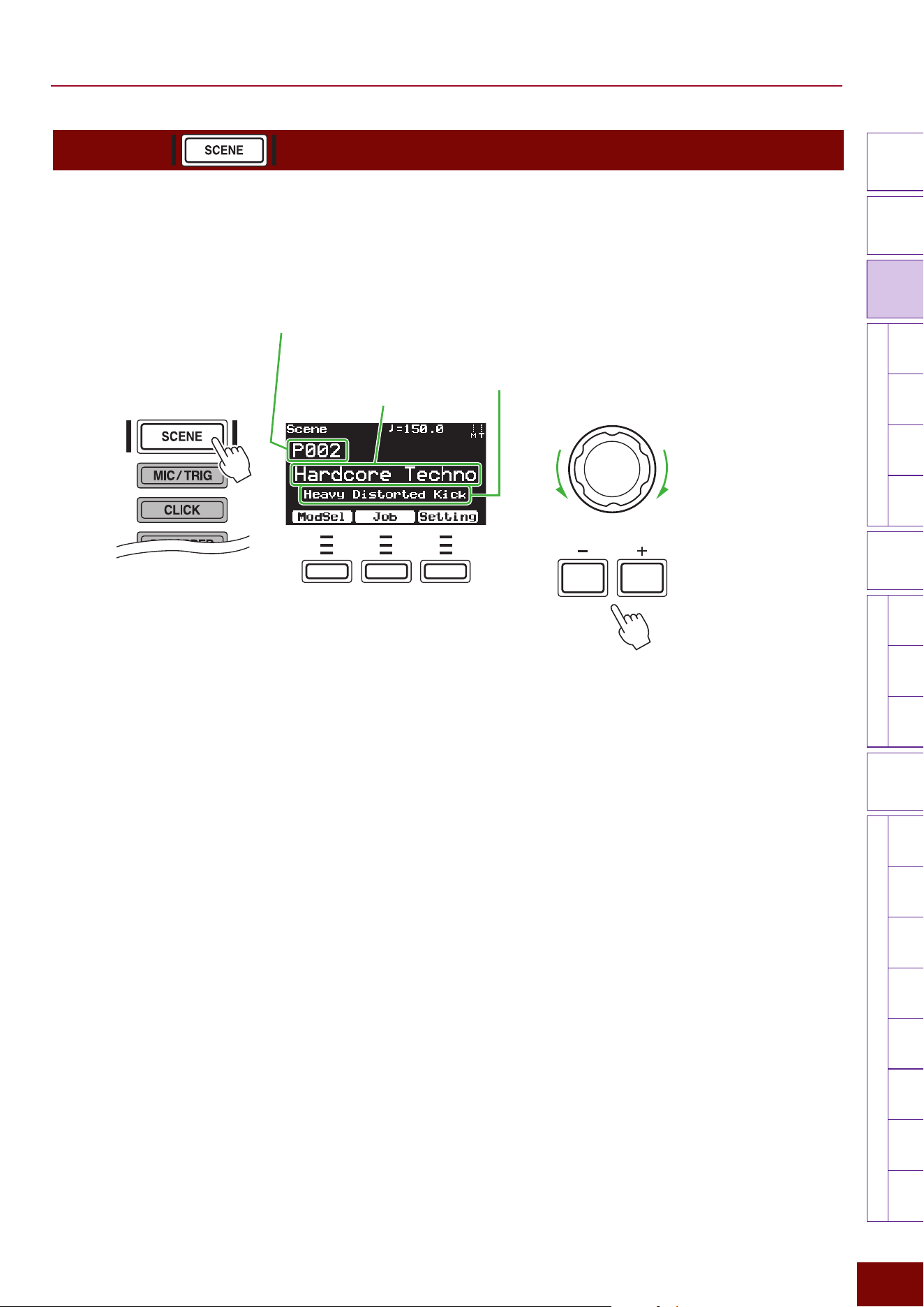
90
Settings in Screens (Parameters)
EAD50 EAD20 User Guide
Modifier
Knobs
LED
Rotary
Faders
[ MIC / TRIG ]
[ SCENE ]
[ CLICK ][ RECORDER ]
[ MENU ]
MicTriggerKitEffectRecorderLooperSamplingUtilityOutputAux In
USB AudioBluetooth
FileFactory
Reset
Version
[
LIVE SET
]
[SCENE]
By selecting the [SCENE] button, this product can recall a variety of performance settings with a single touch of a button, such
as microphone, Trigger sound, and Effect settings. On this screen, the [+]/[–] buttons or a knob can be used to select from
Preset Scenes included in this product. In addition, up to 200 user-defined Scenes can also be created.
NOTE
“Scenes” are composed of various setting parameters. For more information, refer to Page 35.
■ Switching Scenes
In addition to using the [+]/[–] buttons or knob, a foot switch or hitting an electronic drum pad can also be used to switch
Scenes.
Enter the settings via the following screen.
[MIC/TRIG]
"
[F3] Setting
"
Kit
"
Voice
"
Voice Func
■ Playing Music Using a Variety of Scenes
This product includes an extensive selection of Preset Scenes available for a wide variety of performance use cases. For more
information, refer to the List of Preset Scenes (Pages 96 and 102).
■ Creating User-Defined Scenes (User Scenes)
Custom (User Scenes) can be created by configuring modifier knob settings in the screen displayed by pressing [F1] or
changing various settings in other modes and then saving the settings as a unique user-defined Scene (User Scene). For
instructions on how to save User Scenes, refer to Page 95.
NOTICE
Any edits of parameters are cleared whenever another Scene is selected. If settings are intended for creating a User Scene, be sure to
store the settings via the [STORE] button before switching the Scene. For more details, refer to the Page 95.
F1 F2 F3
Scene No.
P***: Preset Scenes (already included)
U***: User Scenes (Scenes created by users)
Scene name
Subname*
NOTE
The “F” in “F1 – F3” refers to “Function” and is used
to name the buttons for explanatory convenience. The
names are not printed on the panel.
*
Some Preset Scenes do not have a subname. Even in
such cases, a subname can be specified when storing
(saving) a User Scene.
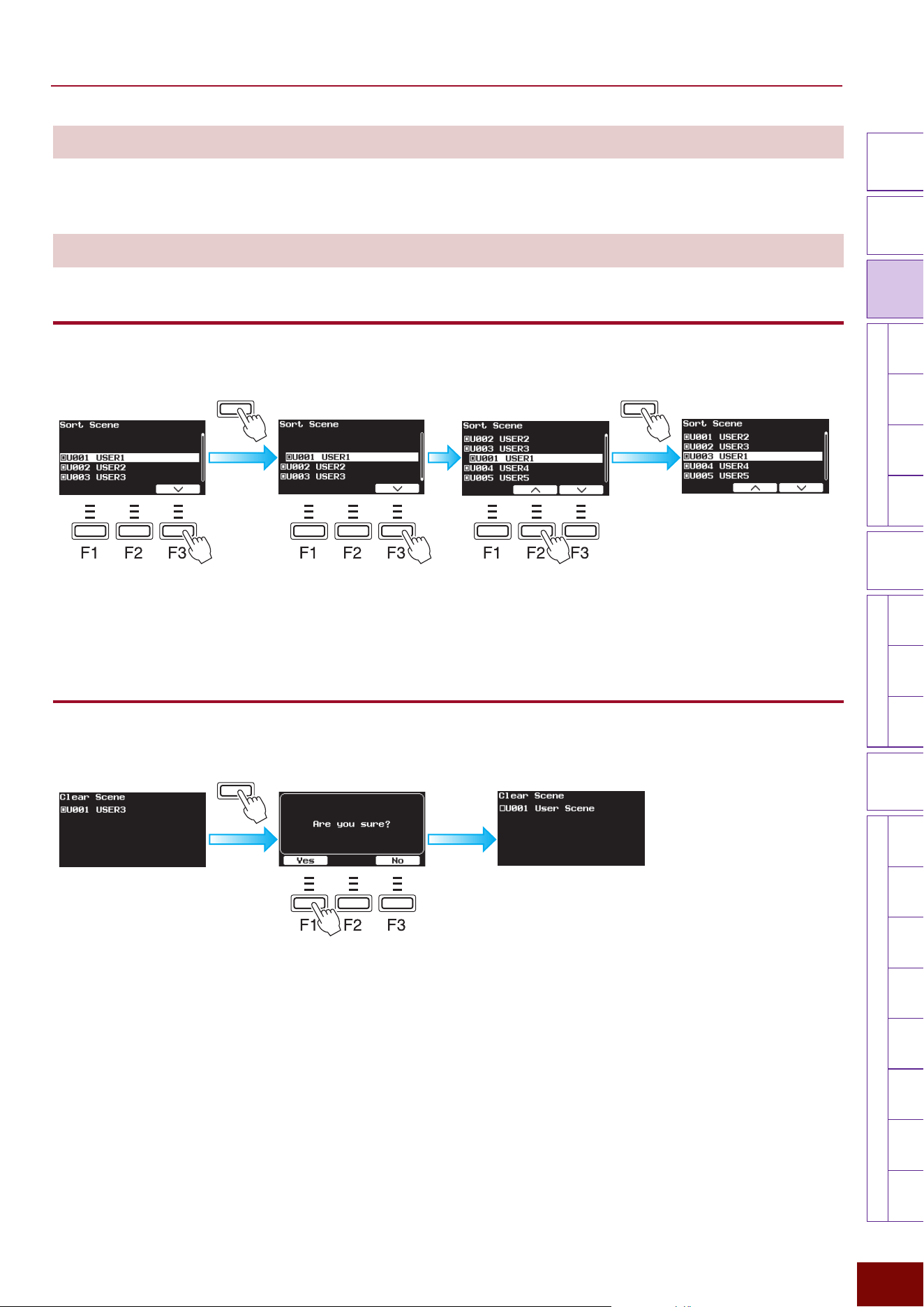
91
Settings in Screens (Parameters)
EAD50 EAD20 User Guide
Modifier
Knobs
LED
Rotary
Faders
[ MIC / TRIG ]
[ SCENE ]
[ CLICK ][ RECORDER ]
[ MENU ]
MicTriggerKitEffectRecorderLooperSamplingUtilityOutputAux In
USB AudioBluetooth
FileFactory
Reset
Version
[
LIVE SET
]
[F1] ModSel
ModSel is an abbreviation for “Modifier Select.” For more details, refer to “Modifier Knob Operations”.
[F2] Job
[F2] Job "Sort
This changes the order of User Scenes created by the user.
ENTERENTER
1.
[F2] and [F3] buttons position
the cursor at the Scene number
with its order to be changed.
3.
[F2] and [F3] button move
Scenes displayed shifted to the
right.
2.
Pressing [ENTER] moves the Scene
with the sequence order to be changed,
by shifting it to the right.
4.
Once the Scene movement destination
is decided, press [ENTER].
After a message appears to indicate
the action is being executed, the new
User Scene order is applied.
[F2] Job "Clear
This reinitializes individual User Scenes created by the user.
ENTER
1.
Use [+]/[−] buttons or the
knob to select the User
Scene to be deleted.
3.
Press the [F1] button
to delete the Scene.
2.
Pressing [ENTER] displays a
confirmation message.
After a message appears to indicate
the action is being executed, the User
Scene initialization is finished.
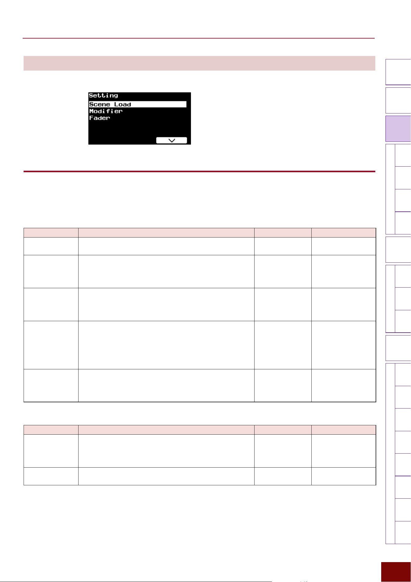
92
Settings in Screens (Parameters)
EAD50 EAD20 User Guide
Modifier
Knobs
LED
Rotary
Faders
[ MIC / TRIG ]
[ SCENE ]
[ CLICK ][ RECORDER ]
[ MENU ]
MicTriggerKitEffectRecorderLooperSamplingUtilityOutputAux In
USB AudioBluetooth
FileFactory
Reset
Version
[
LIVE SET
]
[F3] Setting
This is used to configure related settings when a Scene is used.
[F3] Setting "Scene Load
As indicated on Page 35, Scenes involve saving a variety of parameter settings, so that Scenes can be selected to load all
the settings collectively. When selecting a Scene, whether to apply the parameter setting values saved in the Scene or whether
to ignore them and retain current values can be specified for each parameter. To apply the values saved in the selected Scene,
set the following parameter to “On.” To keep the current values, set the parameter to “Off.”
Page 1/4
Parameter Explanation Setting Default Value
Mic/Kit Volume
Applies to the [MIC/TRIG]
"
[F3] Setting
"
Mic/Kit Vol setting
value.
Off, On On
Mic Applies to all parameter settings displayed by pressing [MIC/
TRIG]
"
[F3] Setting
"
Mic. It includes all settings related to
audio (acoustic drum performance sounds, etc.) inputs via
[MIC/LINE INPUT] jacks on the rear panel.
Off, On On
Trigger
Applies to all settings displayed by pressing [MIC/TRIG]
"
[F3]
Setting
"
Trigger. It includes all settings related to Trigger
signals input via [TRIGGER INPUT] and [FOOT SW] jacks on
the rear panel.
Off, On On
Kit
Applies to almost all settings displayed by pressing [MIC/
TRIG]
"
[F3] Setting
"
Kit. It does not apply to [MIC/TRIG]
"
[F3] Setting
"
Kit
"
Voice
"
Voice Func settings or [MIC/
TRIG]
"
[F3] Setting
"
Kit
"
User Voice settings. It includes all
settings related to electronic sounds (Insts included in drum
kits) produced based on a Trigger signal.
Off, On On
Function
Applies to all settings displayed by pressing [MIC/TRIG]
"
[F3] Setting
"
Kit
"
Voice
"
Voice Func. The settings assign
a variety of functions other than the sound expressed when a
pad is hit.
Off, On On
Page 2/4
Parameter Explanation Setting Default Value
Effect
Applies to all settings displayed by pressing [MIC/TRIG]
"
[F3] Setting
"
Effect. It includes all settings related to Effects
applied to electronic sounds (Insts included in drum kits)
produced based on audio inputs or a Trigger signal.
Off, On On
Tempo
This applies to Click playback and tempo values for certain
Effect types.
Off, On On
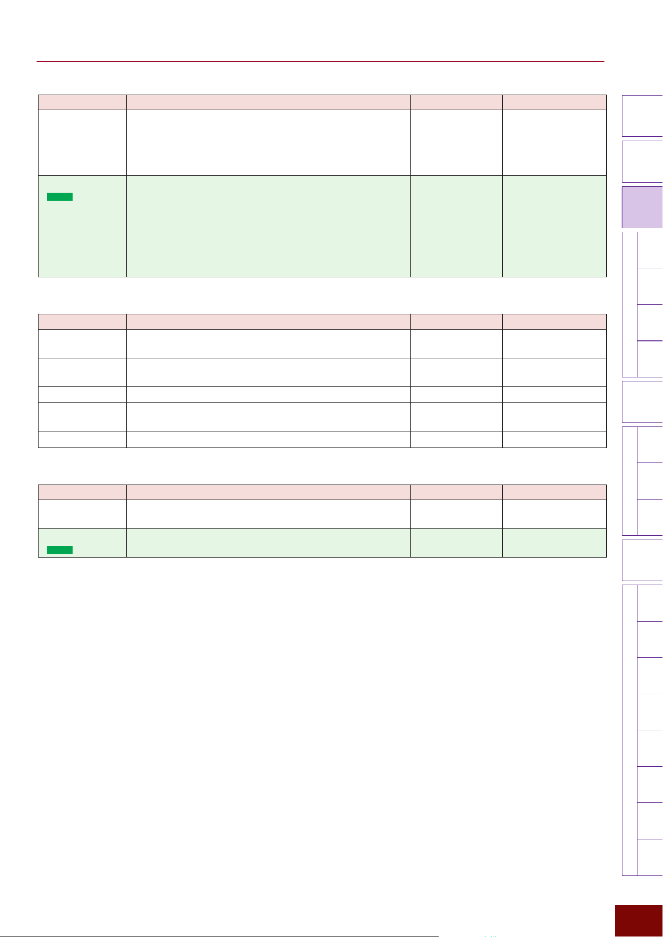
93
Settings in Screens (Parameters)
EAD50 EAD20 User Guide
Modifier
Knobs
LED
Rotary
Faders
[ MIC / TRIG ]
[ SCENE ]
[ CLICK ][ RECORDER ]
[ MENU ]
MicTriggerKitEffectRecorderLooperSamplingUtilityOutputAux In
USB AudioBluetooth
FileFactory
Reset
Version
[
LIVE SET
]
Parameter Explanation Setting Default Value
Modifier Applies to all settings related to modifier knobs. Specifically, it
applies to all settings displayed by pressing the following.
• [SCENE]
"
[F3] Setting
"
Modifier
• While a pop-up window is displayed by operating a modifier
knob
"
[F3] Setting
Off, On On
Fader
(
EAD50
only)
Applies to all settings related to LED rotary fader operations.
Specifically, it applies to settings displayed by pressing the
following.
• [CUSTOM], [MIC], and [TRIG] selection status and fader
function selection status
• [SCENE]
"
[F3] Setting
"
Fader setting
However, it does not apply to setting values specified using
respective faders.
Off, On On
Page 3/4
Parameter Explanation Setting Default Value
Click
Applies to all settings displayed by pressing [CLICK]
"
[F3]
Setting.
Off, On Off
Recorder
Applies to all settings displayed by pressing [RECORDER]
"
[F3] Setting (Recorder, Looper, or Sampling).
Off, On Off
Utility Applies to all settings displayed by pressing [MENU]
"
Utility.
Off, On Off
Output Applies to all settings displayed by pressing [MENU]
"
Output.
Off, On Off
Aux In
Applies to all settings displayed by pressing [MENU]
"
Aux In.
Off, On Off
Page 4/4
Parameter Explanation Setting Default Value
USB Audio
Applies to all settings displayed by pressing [MENU]
"
USB
Audio.
Off, On Off
Bluetooth
(
EAD50
only)
Applies to all settings displayed by pressing [MENU]
"
Bluetooth. This setting is for audio inputs via Bluetooth.
Off, On Off
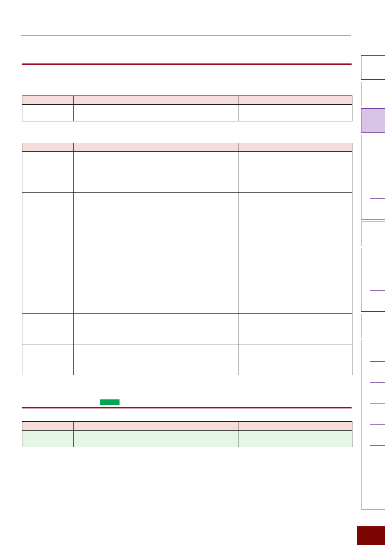
94
Settings in Screens (Parameters)
EAD50 EAD20 User Guide
Modifier
Knobs
LED
Rotary
Faders
[ MIC / TRIG ]
[ SCENE ]
[ CLICK ][ RECORDER ]
[ MENU ]
MicTriggerKitEffectRecorderLooperSamplingUtilityOutputAux In
USB AudioBluetooth
FileFactory
Reset
Version
[
LIVE SET
]
[F3] Setting "Modifier
These are mainly settings related to MIDI messages output using a modifier knob.
Page 1/2
Parameter Explanation Setting Default Value
Modifier Pop-up
This specifies whether or not to display a pop-up window
whenever any modifier knob is operated.
Off, On Always On for Preset
Scenes (Modifier)
Page 2/2
Parameter Explanation Setting Default Value
CC Number
Assigns a MIDI message control change number generated
whenever any modifier knob is operated. Set after the knob is
selected using [F1] ModSel.
Off, 0 – 127 For Preset Scenes
(Modifier), settings
are always set to 18,
19, 80, 81, 82, and 83
successively in order
from knob 1 to knob 6.
CC Channel
Assigns the MIDI channel to use for sending MIDI messages
generated whenever each modifier knob is operated. Set after
the knob is selected using [F1] ModSel.
NOTE
If Global is specified, then the channel is set by [MENU]
"
Utility
"
MIDI Global Channel.
Global, 1 – 16 Always set to Global for
Preset Scenes (Modifier)
CC Port
Assigns the MIDI port to use for sending MIDI messages
generated whenever each modifier knob is operated. Set after
the knob is selected using [F1] ModSel.
NOTE
• If Global is specified, then the port number is set by [MENU]
"
Utility MIDI Global Port.
• If “2” or Global is selected and MIDI Global Port = 2, then
MIDI messages are not sent via [MIDI OUT] terminal for knob
operations.
Global, 1, 2 Always set to Global for
Preset Scenes (Modifier)
CC Min Value
Assigns the minimum data value of MIDI messages generated
whenever each modifier knob is operated. Values less than this
setting are not generated when the knobs are operated. Set after
the knob is selected using [F1] ModSel.
0 – 127 Always set to “0” for
Preset Scenes (Modifier)
CC Max Value
Assigns the maximum data value of MIDI messages generated
whenever each modifier knob is operated. Values greater than
this setting are not generated when the knobs are operated. Set
after the knob is selected using [F1] ModSel.
0 – 127 Always set to “127” for
Preset Scenes (Modifier)
[F3] Setting "Fader (
EAD50
only)
Parameter Explanation Setting Default Value
Fader Pop-up
Specifies whether or not to display a pop-up window whenever
any LED rotary fader is operated.
Off, On Always set to “On” for
Preset Scenes (faders)
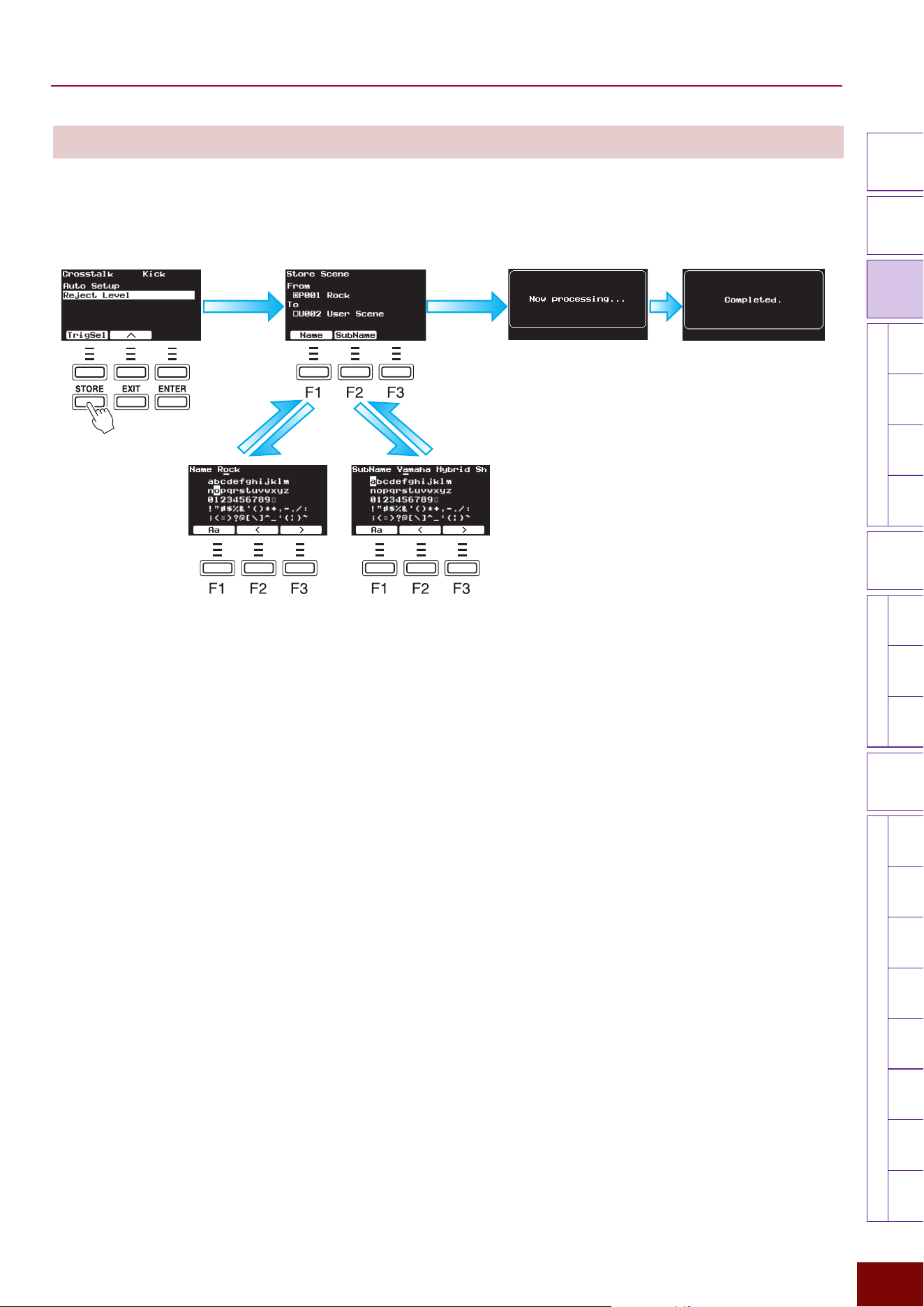
95
Settings in Screens (Parameters)
EAD50 EAD20 User Guide
Modifier
Knobs
LED
Rotary
Faders
[ MIC / TRIG ]
[ SCENE ]
[ CLICK ][ RECORDER ]
[ MENU ]
MicTriggerKitEffectRecorderLooperSamplingUtilityOutputAux In
USB AudioBluetooth
FileFactory
Reset
Version
[
LIVE SET
]
[STORE]
In modes other than [LIVE SET], all current settings can be saved as a User Scene by pressing the [STORE] button, regardless
of the screen display status.
[STORE] Button
[ENTER] button
Select the User Scene number
for the saving destination.
[ENTER]
button
[ENTER]
button
[F1]
Button
[F2]
Button
Assign a User
Scene name.
Assign a User Scene
subname.
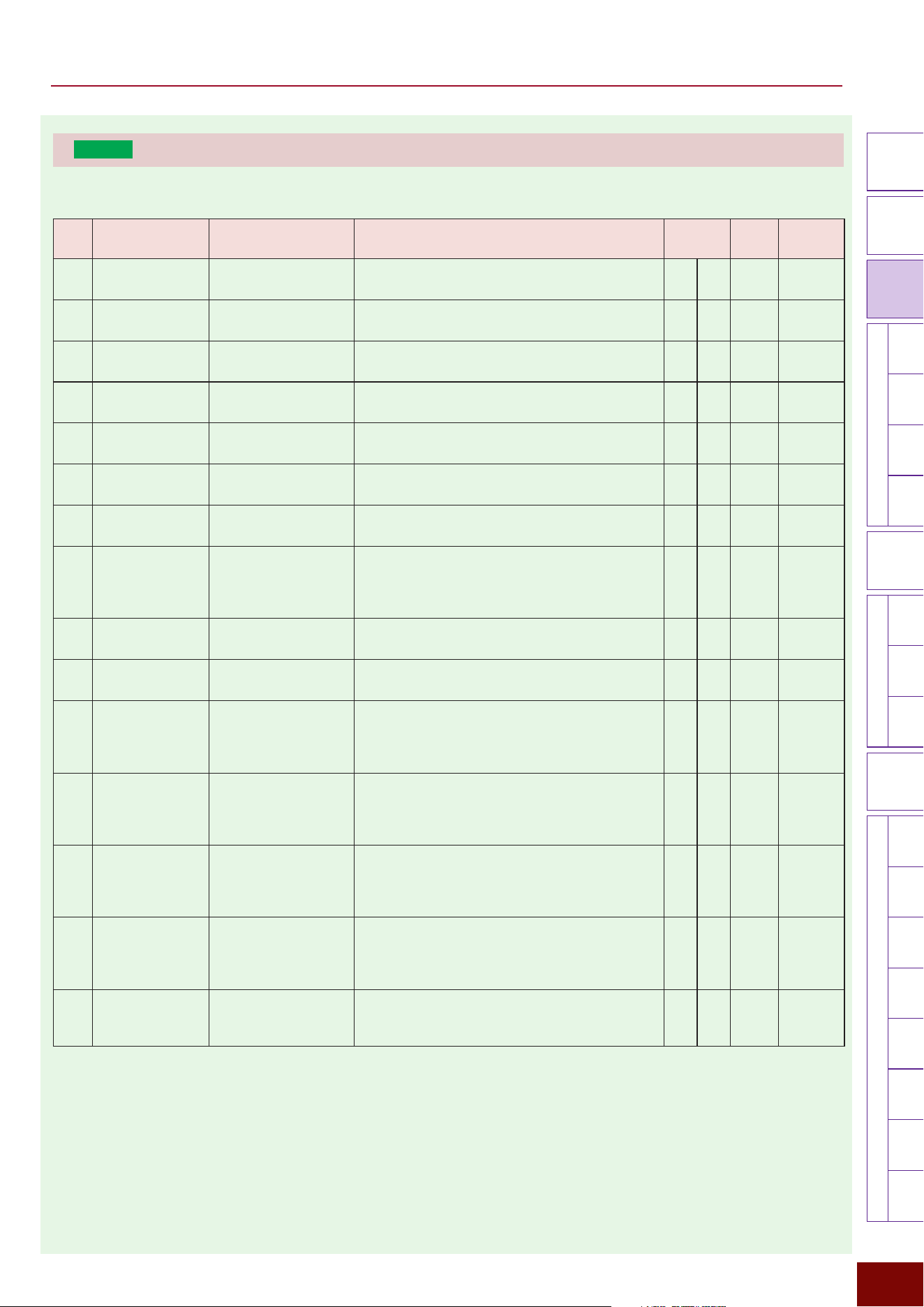
96
Settings in Screens (Parameters)
EAD50 EAD20 User Guide
Modifier
Knobs
LED
Rotary
Faders
[ MIC / TRIG ]
[ SCENE ]
[ CLICK ][ RECORDER ]
[ MENU ]
MicTriggerKitEffectRecorderLooperSamplingUtilityOutputAux In
USB AudioBluetooth
FileFactory
Reset
Version
[
LIVE SET
]
EAD50
List of Preset Scenes
No.
Scene Name Subname Comments Note
Setup**
Foot SW2
Type
P001
Venue This Scene recreates the acoustic of a large live venue,
adding openness and depth to the sound.
A FC7
P002
Hardcore Techno Heavy Distorted Kick This Scene features layered Voices and a distortion
enhanced kick, creating an aggressive, dynamic sound.
*1 A FC7
P003
Analog Delay Mods 2/4/5 for Delay This Scene adds analog delay. The delay sound can
be controlled using Modifiers 2, 4, and 5.
A FC7
P004
Pitch Change Pitch Change - Mod 2 This Scene adds pitch-shifting. Turning Modifier 2
causes the pitch to change dramatically.
A FC7
P005
Good And Bad Classic 1970s Rock This Scene creates a classic big 1970’s rock sound
with reverb.
*1 A HH40
P006
Neo Flanger AmbienceFlanger - Mod 2 This Scene uses an ambience flanger effect, with
noticeable modulation in the high-frequency range.
*1 A FC7
P007
Memories Retro Sound This Scene applies retro-style saturation and
compression, in the character of vintage recordings.
*1 *2 A FC7
P008
Crisp Reverb Modifiers 5/6 for EQ +/- This Scene is good for ‘all-round’ kit use. Modifier 5
controls the EQ character of the reverb (controllable
from Modifier 1) and Modifier 6 controls the EQ
character of the microphones, for all-round control.
A HH40
P009
Old School Clap Timing - Mod 6 This Scene uses a fat kick and clap as Trigger sounds.
Modifier 6 adjusts the timing of the clap.
*1 A FC7
P010
Funk Rock Sn.Trg - Metallic Crack This Scene adds a bright, high-pitched snare drum as
a Trigger sound, well-suited for funk rock grooves.
A FC7
P011
Hard Drum'n'Bass Extra Pad - More Sounds This Scene uses distorted kick and snare sounds as
Triggers, making it suitable for hard-hitting drum and
bass grooves. Connecting external pads gives access
to additional genre specific sounds.
*1 A FC7
P012
Basic EQ Comp Scene Starter This is a Scene Starter. It uses basic EQ and
compression to tighten the transients of mic input
and enhance overall drum kit sound. It serves as a
foundation for creating User Scenes.
*2 A FC7
P013
Bright Gate Mods 2/5 for GatedReverb A useful Bright Gated Scene, which makes the drum
kit more aggressive and cutting. Modifier 2 controls
the gated reverb amount, and Modifier 5 changes the
reverb type.
A HH40
P014
Very Heavy Limit No Dynamics A Scene with very heavy limiting applied. There is very
little dynamic range here, so everything seems loud
and the same volume, and the cymbals seem to ring
for much longer than normal.
*1 A HH40
P015
Electro Pop Snare Trigger - eSnare This Scene assigns an electronic sound as the Trigger
sound. It is especially well-suited for playing pop and
electronic music.
A FC7
*1 Please note that when performing live, you may experience feedback if the monitor speaker is positioned too close to the EAD10. (Due
to use of high-gain Mic Effects and multiple microphones)
*2 These Scenes make it easier to hear the effectiveness of Mic Effects and Trigger Sounds when using closed-back headphones/
earphones, or during playback of your recorded performance.
** For information about setups A to F indicated in
the Setup column, see from Page 37 to 40.
97
Settings in Screens (Parameters)
EAD50 EAD20 User Guide
Modifier
Knobs
LED
Rotary
Faders
[ MIC / TRIG ]
[ SCENE ]
[ CLICK ][ RECORDER ]
[ MENU ]
MicTriggerKitEffectRecorderLooperSamplingUtilityOutputAux In
USB AudioBluetooth
FileFactory
Reset
Version
[
LIVE SET
]
No.
Scene Name Subname Comments Note
Setup**
Foot SW2
Type
P016
Session This Scene assigns muted Trigger sounds, making it
suitable for a wide range of musical contexts.
*2 A FC7
P017
R&B Extra Pad - More Sounds This R&B style Scene assigns simple sine wave kicks
and snap sounds as Trigger sources.
A FC7
P018
Lo-Fi Chill Extra Pad - More Sounds This Scene features Lo-Fi bitcrush and reverb effects,
making it suitable for relaxed, chill-style performances.
Using Trig3, 4, 5, and Foot1 gives access to additional
sounds tailored for chill music.
*2 A FC7
P019
Dubstep Extra Pad - More Sounds This Scene assigns a heavy kick and bright snare
as Trigger sounds, making it suitable for dubstep
performance. Using Trig3, 4, 5, and Foot1 gives
access to additional electronic sounds for expanded
expression.
A FC7
P020
BigKik Room Classic 1970s Rock This Scene creates a classic 1970s rock sound with
punchy bass drum, and big room acoustics
*1 A HH40
P021
Bit Pop Bit Crush - Modifier 6 This Scene uses square wave and white noise sounds
as Triggers, characterized by a bitcrushed texture
reminiscent of 8-bit computers. Modifier 6 controls the
intensity of the bitcrush effect applied to the mic input.
A FC7
P022
V-Shaped EQ Comp Scene Starter This Scene features a V-shaped EQ with emphasised
highs and lows. The compressor smooths out the mic
input and enhances its overall impact. It serves as a
foundation for creating User Scenes.
A FC7
P023
Lo-Fi EQ Comp Scene Starter This Scene features a Lo-Fi EQ and a compression,
giving it a raw yet focused character. The compressor
evens out the mic input, adding a sense of punch and
presence. It serves as a foundation for creating User
Scenes.
*2 A FC7
P024
EAD10 EQ Comp Scene Starter This Scene brings back the compressor effect originally
found in the EAD10, but now carefully re-tuned. It
serves as a foundation for creating User Scenes.
*1 A FC7
P025
Limiter Scene Starter This Scene uses a limiter effect. Its rough tonal
character adds punch to the sound. It serves as a
foundation for creating User Scenes.
A FC7
P026
Pitch Drop Bigger drums and cymbals This Scene takes the pitch of the drums and cymbals
and bends the pitch down so all drums and cymbals
sound bigger, lower and more powerful.
*1 A HH40
P027
Hall Reverb Mods 1/4/5 for Reverb This Scene features reverb that creates a sense of
spaciousness, similar to performing in a hall. The
reverb sound can be controlled using Modifiers 1, 4,
and 5.
A FC7
P028
Dark Gate Transient Gating - Mod 2 This Scene uses a gate effect with a high threshold.
The sound is cut off immediately after it's Triggered,
creating a unique and creative tonal shift.
A FC7
P029
Dance Pop Extra Pad - More Sounds This Scene uses kick and clap sounds with a strong
attack as Trigger Voices, making it suitable for dance-
based, pop-style performances. Using Trig3, 4, 5, and
Foot1 gives access to additional electronic sounds for
expanded expression.
A FC7
P030
Rock This Scene assigns dry, heavy Trigger sounds to
the kick and snare drums, suitable for rock-style
performances.
*1 A FC7
*1 Please note that when performing live, you may experience feedback if the monitor speaker is positioned too close to the EAD10. (Due
to use of high-gain Mic Effects and multiple microphones)
*2 These Scenes make it easier to hear the effectiveness of Mic Effects and Trigger Sounds when using closed-back headphones/
earphones, or during playback of your recorded performance.
98
Settings in Screens (Parameters)
EAD50 EAD20 User Guide
Modifier
Knobs
LED
Rotary
Faders
[ MIC / TRIG ]
[ SCENE ]
[ CLICK ][ RECORDER ]
[ MENU ]
MicTriggerKitEffectRecorderLooperSamplingUtilityOutputAux In
USB AudioBluetooth
FileFactory
Reset
Version
[
LIVE SET
]
No.
Scene Name Subname Comments Note
Setup**
Foot SW2
Type
P031
Crunch Drum Kit Distortion This Scene features a crunch-style distortion effect,
producing a gritty, aggressive sound.
*1 A FC7
P032
Dub Mods 2/4/5 for Delay This Scene features delay and phaser effects. Turning
Modifier 4 changes the delay time. Using Trig3, 4, 5,
and Foot1 allows you to Trigger percussion sounds.
*1 A FC7
P033
Funk Pop Snare Trigger - Clap This Scene uses a loose clap as the Trigger Voice,
suitable for funk and pop-style performances.
A FC7
P034
Mountain Swirl Classic 1970s Rock This Scene creates a 1970s rock kit with classic big
drum sound and light phaser effect
*1 A HH40
P035
Shimmer Reverb Mods 1/4/5/6 for Reverb This Scene features a shimmer reverb effect, offering a
distinctive ethereal character. The reverb sound can be
controlled using Modifiers 1, 4, 5 and 6.
A FC7
P036
Hard Rock This Scene uses a loose kick and a tight snare as
Trigger Voices, suitable for hard rock performances.
A FC7
P037
Crush Wave Folder - Mod 2 This Scene features a unique crushing distortion effect.
Using Trig3, 4, 5, and Foot1 provides access to sounds
suited for more creative applications.
*1 A FC7
P038
Very Heavy Comp No Dynamics A Scene with very heavy compression applied. There
is very little dynamic range here, so everything seems
squashed and the same volume, and the cymbals
seem to ‘pump’ when hit, making them sound much
bigger.
*1 A HH40
P039
8th Delay Click Tempo - Modifier 6 A modern style clean delay on the whole kit. The delay
is sync’ed to the Click at 8th notes. The Click and delay
speed is adjustable on Modifier 6.
*1 A HH40
P040
Dot8 Delay Click Tempo - Modifier 6 A modern style clean delay on the whole kit. The delay
is sync’ed to the Click at dotted 8th notes (3x 16th
notes). The Click and delay speed is adjustable on
Modifier 6.
A HH40
P041
8T Delay Click Tempo - Modifier 6 A modern style clean delay on the whole kit. The delay
is sync’ed to the Click at 8th note triplets. The Click and
delay speed is adjustable on Modifier 6.
*1 A HH40
P042
Amb Distortion Trigger Distortion This Scene uses a distorted ambient waveform as the
Trigger Voice. The mic input is unaffected by distortion,
helping to reduce the risk of feedback. Modifier 5
controls the distortion level for the kick and snare
Triggers individually.
A FC7
P043
Hi/Lo PitchDelay Variation- Modifiers 5/6 This Scene makes the pitch of lower instruments go up
in steps, and the pitch of high instruments go down in
steps.
A FC7
P044
Amp Simulator Drum Kit Distortion This Scene features guitar amp-style distortion. It
produces a lo-fi, overdriven sound.
*1 A FC7
P045
Pop Rock Clap - Snare Trigger This Scene uses powerful kick and clap sounds as
Triggers, making it suitable for a wide range of musical
genres.
A FC7
*1 Please note that when performing live, you may experience feedback if the monitor speaker is positioned too close to the EAD10. (Due
to use of high-gain Mic Effects and multiple microphones)
*2 These Scenes make it easier to hear the effectiveness of Mic Effects and Trigger Sounds when using closed-back headphones/
earphones, or during playback of your recorded performance.
99
Settings in Screens (Parameters)
EAD50 EAD20 User Guide
Modifier
Knobs
LED
Rotary
Faders
[ MIC / TRIG ]
[ SCENE ]
[ CLICK ][ RECORDER ]
[ MENU ]
MicTriggerKitEffectRecorderLooperSamplingUtilityOutputAux In
USB AudioBluetooth
FileFactory
Reset
Version
[
LIVE SET
]
No.
Scene Name Subname Comments Note
Setup**
Foot SW2
Type
P046
Timbale Break Extra Pad - More Sounds This Scene has a natural acoustic drum kit sound, with
timbale and cowbell on the external pads.
A HH40
P047
Electro Rock Extra Pad - More Sounds This Scene uses aggressive kick and snare drum
sounds as Triggers.Using Trig3, 4, 5, and Foot1 gives
access to additional electronic sounds for expanded
expression.
*1 A FC7
P048
Hiphop Clap Timing - Modifier 6 This Scene uses fat kick and clap sounds as Triggers.
Modifier 6 adjusts the timing of the clap.
*1 A FC7
P049
DigiBell Harmonics and delay This Scene adds modulation and harmonics to the
sound of the kit and makes drums sound like digital
bells.
A HH40
P050
Composite Kick Blend Modifiers 4/5/6 This Scene allows the creation of almost ANY
character of bass drum, by combining the samples
on Modifiers 4,5,6. The sample on Modifier 4 is an
short electronic click with lots of attack. The sample on
Modifier 5 is an acoustic boom with lots of body, and
the sample on Modifier 6 is an electronic kick sound
with lots of weight. By combining these in different
amounts, bass drum sounds for ANY situation can be
created.
*2 A HH40
P051
BigKik Reflectn Classic 1970s Rock This Scene creates a classic 1970s rock sound with
punchy bass drum, and early reflection reverb for more
cut
*1 A HH40
P052
BigKik Phaser Classic 1970s Rock This Scene creates a classic 1970s rock kit with
punchy bass drum, and phasing
A HH40
P053
EDM Extra Pad - More Sounds This Scene uses kick and electro snare sounds with
emphasized attack as Triggers.Using Trig3, 4, 5, and
Foot1 gives access to additional electronic sounds for
expanded expression.
A FC7
P054
Funk This Scene uses loose kick and tight snare sounds as
Triggers, well-suited for old-school funk performances.
*2 A FC7
P055
Big Beat Extra Pad - More Sounds This Scene uses distorted, hard-edged kick and snare
sounds as Triggers. Using Trig3, 4, 5, and Foot1 gives
access to additional electronic sounds for expanded
expression.
A FC7
*1 Please note that when performing live, you may experience feedback if the monitor speaker is positioned too close to the EAD10. (Due
to use of high-gain Mic Effects and multiple microphones)
*2 These Scenes make it easier to hear the effectiveness of Mic Effects and Trigger Sounds when using closed-back headphones/
earphones, or during playback of your recorded performance.
100
Settings in Screens (Parameters)
EAD50 EAD20 User Guide
Modifier
Knobs
LED
Rotary
Faders
[ MIC / TRIG ]
[ SCENE ]
[ CLICK ][ RECORDER ]
[ MENU ]
MicTriggerKitEffectRecorderLooperSamplingUtilityOutputAux In
USB AudioBluetooth
FileFactory
Reset
Version
[
LIVE SET
]
No.
Scene Name Subname Comments Note
Setup**
Foot SW2
Type
P056
Breakdown Extra Pad - More Sounds This Scene has a distorted acoustic drum kit sound,
with small electronic percussion on the external pads.
*1 A HH40
P057
Metal For Triggers On Drums This Scene assigns heavy Trigger sounds with sharp
attack. Modifier 6 adjusts the EQ of the Trigger sounds,
allowing you to emphasize their attack.
B FC7
P058
RotoRoom For Triggers On Drums This Scene assigns heavy Trigger sounds with sharp
attack, reminiscent of rotary tuned toms..
B HH40
P059
Buzz Air For Triggers On Drums This Scene features a distinctive texture that combines
the ambient feel of room mics with snare buzz-like
noise.
B FC7
P060
VintageRoom For Triggers On Drums This Scene allows you to quickly add a vintage drum
sound to all the drums on your acoustic drum kit.
*2 B HH40
P061
Rock+GatedFX For Triggers On Drums This Scene allows you to quickly add rock drum sounds
to all the drums on your acoustic drum kit, but you also
have access to big gated effects which are controllable
with Modifier 2,4.
B HH40
P062
AnalogueRoom For Triggers On Drums This Scene allows you to quickly add analogue synth
drum sounds to all the drums on your acoustic drum
kit.
B HH40
P063
Gate Reverb For Triggers On Drums This Scene features a short gated reverb effect. B FC7
P064
Drum&BassUK For Triggers On Drums This Scene allows you to quickly layer small tight
electronic sounds onto all the drums on your acoustic
drum kit, for an instant drum and bass sound.
B HH40
P065
[+OH DSU] BEQC Add DSU50 as OH Mic This Scene is based on P012: Basic EQ Comp, with
one more DSU50 microphone added. 3–4Ch configure
the additional DSU50 as an overhead (OH) mic, with
EQ and effects tuned to emphasize the cymbals’
high-frequency range. Adjust gain as needed.
*1 *2 C, D FC7
*1 Please note that when performing live, you may experience feedback if the monitor speaker is positioned too close to the EAD10. (Due
to use of high-gain Mic Effects and multiple microphones)
*2 These Scenes make it easier to hear the effectiveness of Mic Effects and Trigger Sounds when using closed-back headphones/
earphones, or during playback of your recorded performance.
101
Settings in Screens (Parameters)
EAD50 EAD20 User Guide
Modifier
Knobs
LED
Rotary
Faders
[ MIC / TRIG ]
[ SCENE ]
[ CLICK ][ RECORDER ]
[ MENU ]
MicTriggerKitEffectRecorderLooperSamplingUtilityOutputAux In
USB AudioBluetooth
FileFactory
Reset
Version
[
LIVE SET
]
No.
Scene Name Subname Comments Note
Setup**
Foot SW2
Type
P066
[+OH DSU] F-Rk Add DSU50 as OH Mic This Scene is based on P010:Funk Rock, with one
more DSU50 microphone added. 3–4Ch configure
the additional DSU50 as an overhead (OH) mic, with
EQ and effects tuned to emphasize the cymbals’
high-frequency range. Adjust gain as needed.
*1 C, D FC7
P067
[+Room DSU] BEQC Add DSU50 as Room Mic This Scene is based on P012: Basic EQ Comp, with
one more DSU50 microphone added. The additional
DSU50 serves as a room mic; use the C or D setup as
the baseline and place it farther from the kit as needed.
3–4Ch have EQ and effects tailored to emphasize room
ambience and a sense of air. Adjust gain as needed.
*1 *2 C, D FC7
P068
[+Room DSU] Rock Add DSU50 as Room Mic This Scene is based on P030:Rock, with one more
DSU50 microphone added. The additional DSU50
serves as a room mic; use the C or D setup as the
baseline and place it farther from the kit as needed.
3–4Ch have EQ and effects tailored to emphasize room
ambience and a sense of air. Adjust gain as needed.
*1 C, D FC7
P069
[+OH ExMic] BEQC Add External Mics as OH This Scene uses two additional microphones alongside
P012: Basic EQ Comp. By inserting the extra DSU50
on channels 3–4 and placing it in the overhead
position, it captures cymbal highs with greater clarity.
The gain for channels 3–4 is set to 0 and phantom
power is turned off, so please adjust as needed.
*1 *2 E FC7
P070
[Multi-Mic Tmpl] Multi-Mic Template This is a convenient template Scene for multi-mic
setups. Starting from Mic1 channel, it corresponds to
OH L, OH R, Kick, Snare, and HH. Each channel’s gain
is set to 0 and phantom power is turned off, so please
adjust as needed.
F FC7
P071
Dry No Effect This Scene has no Effect, Trigger sound, or Modifier
function assigned. This is useful for checking the
source of a microphone input or when creating a
Scene from nothing.
A FC7
*1 Please note that when performing live, you may experience feedback if the monitor speaker is positioned too close to the EAD10. (Due
to use of high-gain Mic Effects and multiple microphones)
*2 These Scenes make it easier to hear the effectiveness of Mic Effects and Trigger Sounds when using closed-back headphones/
earphones, or during playback of your recorded performance.
102
Settings in Screens (Parameters)
EAD50 EAD20 User Guide
Modifier
Knobs
LED
Rotary
Faders
[ MIC / TRIG ]
[ SCENE ]
[ CLICK ][ RECORDER ]
[ MENU ]
MicTriggerKitEffectRecorderLooperSamplingUtilityOutputAux In
USB AudioBluetooth
FileFactory
Reset
Version
[
LIVE SET
]
EAD20
List of Preset Scenes
No.
Scene Name Subname Comments Note
Setup**
P001
Venue This Scene recreates the acoustic of a large live venue, adding
openness and depth to the sound.
A
P002
Hardcore Techno Heavy Distorted Kick This Scene features layered Voices and a distortion enhanced kick,
creating an aggressive, dynamic sound.
*1 A
P003
Analog Delay Mods 2/4/5 for Delay This Scene adds analog delay. The delay sound can be controlled
using Modifiers 2, 4, and 5.
A
P004
Pitch Change Pitch Change - Mod 2 This Scene adds pitch-shifting. Turning Modifier 2 causes the pitch
to change dramatically.
A
P005
Good And Bad Classic 1970s Rock This Scene creates a classic big 1970’s rock sound with reverb. *1 A
P006
Neo Flanger AmbienceFlanger - Mod 2 This Scene uses an ambience flanger effect, with noticeable
modulation in the high-frequency range.
*1 A
P007
Memories Retro Sound This Scene applies retro-style saturation and compression, in the
character of vintage recordings.
*1 *2 A
P008
Crisp Reverb Modifiers 5/6 for EQ +/- This Scene is good for ‘all-round’ kit use. Modifier 5 controls the EQ
character of the reverb (controllable from Modifier 1) and Modifier 6
controls the EQ character of the microphones, for all-round control.
A
P009
Old School Clap Timing - Mod 6 This Scene uses a fat kick and clap as Trigger sounds. Modifier 6
adjusts the timing of the clap.
*1 A
P010
Funk Rock Sn.Trg - Metallic Crack This Scene adds a bright, high-pitched snare drum as a Trigger
sound, well-suited for funk rock grooves.
A
P011
Hard Drum'n'Bass Extra Pad - More Sounds This Scene uses distorted kick and snare sounds as Triggers,
making it suitable for hard-hitting drum and bass grooves. Using
Trig3, 4, 5, and Foot1 gives access to additional genre specific
sounds.
*1 A
P012
Basic EQ Comp Scene Starter This is a Scene Starter. It uses basic EQ and compression to
tighten the transients of mic input and enhance overall drum kit
sound. It serves as a foundation for creating User Scenes.
*2 A
P013
Bright Gate Mods 2/5 for GatedReverb A useful Bright Gated Scene, which makes the drum kit more
aggressive and cutting. Modifier 2 controls the gated reverb amount,
and Modifier 5 changes the reverb type.
A
P014
Very Heavy Limit No Dynamics A Scene with very heavy limiting applied. There is very little
dynamic range here, so everything seems loud and the same
volume, and the cymbals seem to ring for much longer than normal.
*1 A
P015
Electro Pop Snare Trigger - eSnare This Scene assigns electronic sounds as Triggers, making it
suitable for pop and electro-style performances.
A
** For information about setups A and B in the
Setup column, see from Page 37 to 40.
*1 Please note that when performing live, you may experience feedback if the monitor speaker is positioned too close to the EAD10. (Due
to use of high-gain Mic Effects and multiple microphones)
*2 These Scenes make it easier to hear the effectiveness of Mic Effects and Trigger Sounds when using closed-back headphones/
earphones, or during playback of your recorded performance.
103
Settings in Screens (Parameters)
EAD50 EAD20 User Guide
Modifier
Knobs
LED
Rotary
Faders
[ MIC / TRIG ]
[ SCENE ]
[ CLICK ][ RECORDER ]
[ MENU ]
MicTriggerKitEffectRecorderLooperSamplingUtilityOutputAux In
USB AudioBluetooth
FileFactory
Reset
Version
[
LIVE SET
]
No.
Scene Name Subname Comments Note
Setup**
P016
Session This Scene assigns muted Trigger sounds, making it suitable for a
wide range of musical contexts.
*2 A
P017
Lo-Fi Chill Extra Pad - More Sounds This Scene features Lo-Fi bitcrush and reverb effects, making it
suitable for relaxed, chill-style performances. Using Trig3, 4, 5, and
Foot1 gives access to additional sounds tailored for chill music.
*2 A
P018
Dubstep Extra Pad - More Sounds This Scene assigns a heavy kick and bright snare as Trigger
sounds, making it suitable for dubstep performance. Using Trig3,
4, 5, and Foot1 gives access to additional electronic sounds for
expanded expression.
A
P019
BigKik Room Classic 1970s Rock This Scene creates a classic 1970s rock sound with punchy bass
drum, and big room acoustics
*1 A
P020
Bit Pop Bit Crush - Modifier 6 This Scene uses square wave and white noise sounds as
Triggers, characterized by a bitcrushed texture reminiscent of 8-bit
computers. Modifier 6 controls the intensity of the bitcrush effect
applied to the mic input.
A
P021
V-Shaped EQ Comp Scene Starter This Scene features a V-shaped EQ with emphasised highs and
lows. The compressor smooths out the mic input and enhances its
overall impact. It serves as a foundation for creating User Scenes.
A
P022
EAD10 EQ Comp Scene Starter This Scene brings back the compressor effect originally found in
the EAD10, but now carefully re-tuned. It serves as a foundation for
creating User Scenes.
*1 A
P023
Limiter Scene Starter This Scene uses a limiter effect. Its rough tonal character adds
punch to the sound. It serves as a foundation for creating User
Scenes.
A
P024
Pitch Drop Bigger drums and cymbals This Scene takes the pitch of the drums and cymbals and bends
the pitch down so all drums and cymbals sound bigger, lower and
more powerful.
*1 A
P025
Hall Reverb Mods 1/4/5 for Reverb This Scene features reverb that creates a sense of spaciousness,
similar to performing in a hall. The reverb sound can be controlled
using Modifiers 1, 4, and 5.
A
P026
Dark Gate Transient Gating - Mod 2 This Scene uses a gate effect with a high threshold. The sound
is cut off immediately after it's Triggered, creating a unique and
creative tonal shift.
A
P027
Dance Pop Extra Pad - More Sounds This Scene uses kick and clap sounds with a strong attack as
Trigger Voices, making it suitable for dance-based, pop-style
performances. Using Trig3, 4, 5, and Foot1 gives access to
additional electronic sounds for expanded expression.
A
P028
Rock This Scene assigns dry, heavy Trigger sounds to the kick and snare
drums, suitable for rock-style performances.
*1 A
P029
Crunch Drum Kit Distortion This Scene features a crunch-style distortion effect, producing a
gritty, aggressive sound.
*1 A
P030
Dub Mods 2/4/5 for Delay This Scene features delay and phaser effects. Turning Modifier 4
changes the delay time. Using Trig3, 4, 5, and Foot1 allows you to
Trigger percussion sounds.
*1 A
*1 Please note that when performing live, you may experience feedback if the monitor speaker is positioned too close to the EAD10. (Due
to use of high-gain Mic Effects and multiple microphones)
*2 These Scenes make it easier to hear the effectiveness of Mic Effects and Trigger Sounds when using closed-back headphones/
earphones, or during playback of your recorded performance.
104
Settings in Screens (Parameters)
EAD50 EAD20 User Guide
Modifier
Knobs
LED
Rotary
Faders
[ MIC / TRIG ]
[ SCENE ]
[ CLICK ][ RECORDER ]
[ MENU ]
MicTriggerKitEffectRecorderLooperSamplingUtilityOutputAux In
USB AudioBluetooth
FileFactory
Reset
Version
[
LIVE SET
]
No.
Scene Name Subname Comments Note
Setup**
P031
Funk Pop Snare Trigger - Clap This Scene uses a loose clap as the Trigger Voice, suitable for funk
and pop-style performances.
A
P032
Shimmer Reverb Mods 1/4/5/6 for Reverb This Scene features a shimmer reverb effect, offering a distinctive
ethereal character. The reverb sound can be controlled using
Modifiers 1, 4, 5 and 6.
A
P033
Hard Rock This Scene uses a loose kick and a tight snare as Trigger Voices,
suitable for hard rock performances.
A
P034
Crush Wave Folder - Mod 2 This Scene features a unique crushing distortion effect. Using Trig3,
4, 5, and Foot1 provides access to sounds suited for more creative
applications.
*1 A
P035
Very Heavy Comp No Dynamics A Scene with very heavy compression applied. There is very little
dynamic range here, so everything seems squashed and the same
volume, and the cymbals seem to ‘pump’ when hit, making them
sound much bigger.
*1 A
P036
8th Delay Click Tempo - Modifier 6 A modern style clean delay on the whole kit. The delay is sync’ed
to the Click at 8th notes. The Click and delay speed is adjustable on
Modifier 6.
*1 A
P037
Dot8 Delay Click Tempo - Modifier 6 A modern style clean delay on the whole kit. The delay is sync’ed
to the Click at dotted 8th notes (3x 16th notes). The Click and delay
speed is adjustable on Modifier 6.
A
P038
8T Delay Click Tempo - Modifier 6 A modern style clean delay on the whole kit. The delay is sync’ed
to the Click at 8th note triplets. The Click and delay speed is
adjustable on Modifier 6.
*1 A
P039
Hi/Lo PitchDelay Variation- Modifiers 5/6 This Scene makes the pitch of lower instruments go up in steps,
and the pitch of high instruments go down in steps.
A
P040
Timbale Break Extra Pad - More Sounds This Scene has a natural acoustic drum kit sound, with timbale and
cowbell on the external pads.
A
P041
Electro Rock Extra Pad - More Sounds This Scene uses aggressive kick and snare drum sounds as
Triggers.Using Trig3, 4, 5, and Foot1 gives access to additional
electronic sounds for expanded expression.
*1 A
P042
Composite Kick Blend Modifiers 4/5/6 This Scene allows the creation of almost ANY character of bass
drum, by combining the samples on Modifiers 4,5,6. The sample on
Modifier 4 is an short electronic click with lots of attack. The sample
on Modifier 5 is an acoustic boom with lots of body, and the sample
on Modifier 6 is an an electronic kick sound with lots of weight. By
combining these in different amounts, bass drum sounds for ANY
situation can be created.
*2 A
P043
BigKik Phaser Classic 1970s Rock This Scene creates a classic 1970s rock kit with punchy bass drum,
and phasing
A
P044
EDM Extra Pad - More Sounds This Scene uses kick and electro snare sounds with emphasized
attack as Triggers.Using Trig3, 4, 5, and Foot1 gives access to
additional electronic sounds for expanded expression.
A
P045
Big Beat Extra Pad - More Sounds This Scene uses distorted, hard-edged kick and snare sounds as
Triggers. Using Trig3, 4, 5, and Foot1 gives access to additional
electronic sounds for expanded expression.
A
*1 Please note that when performing live, you may experience feedback if the monitor speaker is positioned too close to the EAD10. (Due
to use of high-gain Mic Effects and multiple microphones)
*2 These Scenes make it easier to hear the effectiveness of Mic Effects and Trigger Sounds when using closed-back headphones/
earphones, or during playback of your recorded performance.
105
Settings in Screens (Parameters)
EAD50 EAD20 User Guide
Modifier
Knobs
LED
Rotary
Faders
[ MIC / TRIG ]
[ SCENE ]
[ CLICK ][ RECORDER ]
[ MENU ]
MicTriggerKitEffectRecorderLooperSamplingUtilityOutputAux In
USB AudioBluetooth
FileFactory
Reset
Version
[
LIVE SET
]
No.
Scene Name Subname Comments Note
Setup**
P046
RotoRoom For Triggers On Drums This Scene assigns heavy Trigger sounds with sharp attack,
reminiscent of rotary tuned toms..
B
P047
Buzz Air For Triggers On Drums This Scene features a distinctive texture that combines the ambient
feel of room mics with snare buzz-like noise.
B
P048
Rock+GatedFX For Triggers On Drums This Scene allows you to quickly add rock drum sounds to all the
drums on your acoustic drum kit, but you also have access to big
gated effects which are controllable with Modifier 2,4.
B
P049
AnalogueRoom For Triggers On Drums This Scene allows you to quickly add analogue synth drum sounds
to all the drums on your acoustic drum kit.
B
P050
Drum&BassUK For Triggers On Drums This Scene allows you to quickly layer small tight electronic sounds
onto all the drums on your acoustic drum kit, for an instant drum
and bass sound.
B
P051
Dry No Effect This Scene has no Effect, Trigger sound, or Modifier function
assigned. This is useful for checking the source of a microphone
input or when creating a Scene from nothing.
A
*1 Please note that when performing live, you may experience feedback if the monitor speaker is positioned too close to the EAD10. (Due
to use of high-gain Mic Effects and multiple microphones)
*2 These Scenes make it easier to hear the effectiveness of Mic Effects and Trigger Sounds when using closed-back headphones/
earphones, or during playback of your recorded performance.
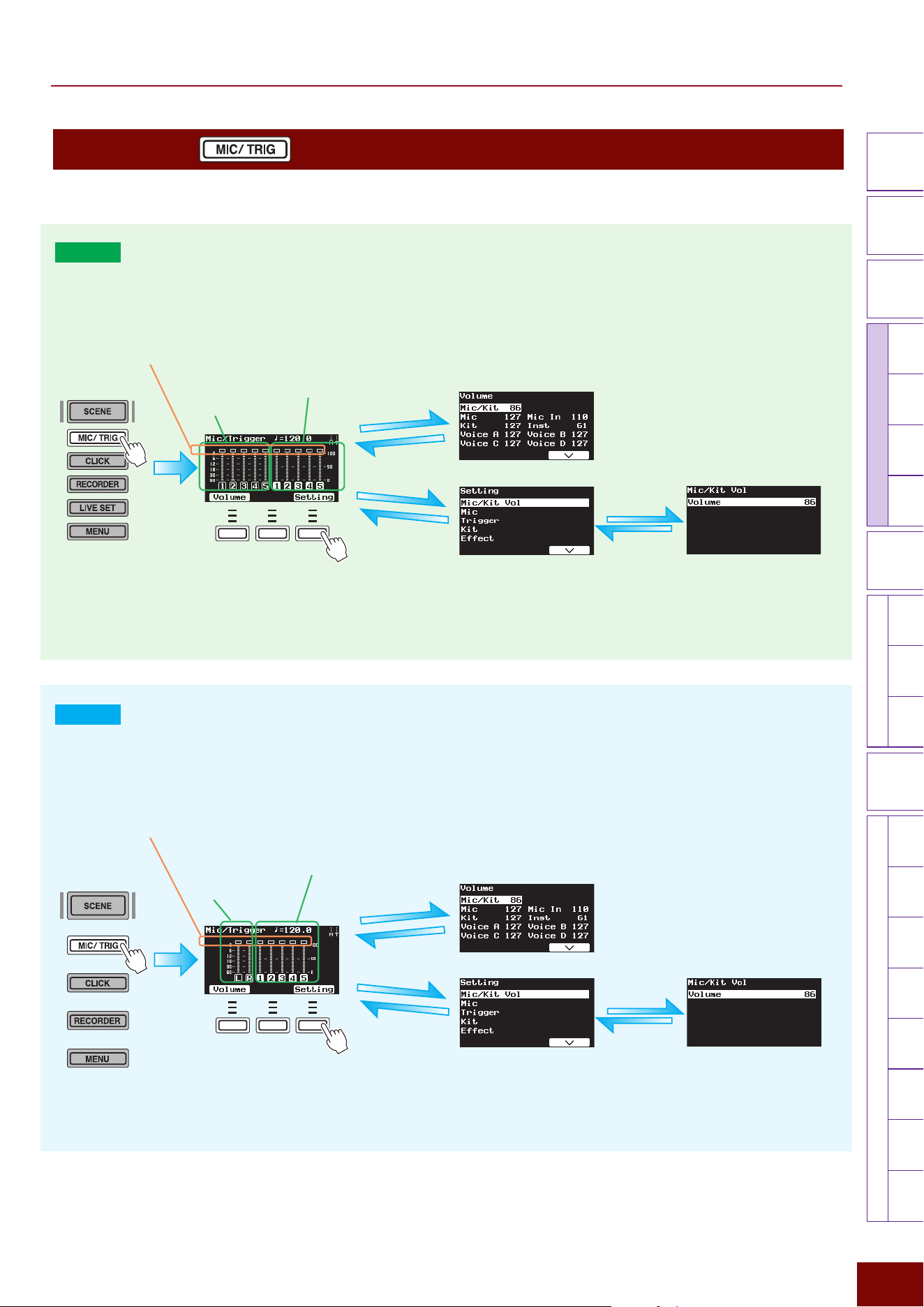
106
Settings in Screens (Parameters)
EAD50 EAD20 User Guide
Modifier
Knobs
LED
Rotary
Faders
[ MIC / TRIG ]
[ SCENE ][ CLICK ][ RECORDER ]
[ MENU ]
MicTriggerKitEffectRecorderLooperSamplingUtilityOutputAux In
USB AudioBluetooth
FileFactory
Reset
Version
[
LIVE SET
]
[MIC/TRIG]
When the [MIC/TRIG] button is lit, settings for mic and Trigger sounds are specified.
EAD50
Immediately after the [MIC/TRIG] button is pressed, meters indicating the real-time status of signal inputs from [MIC/LINE] and
[TRIGGER INPUT] jacks are displayed on the top screen. The rectangular lamps at the top of the meters function as peak input
signal indicators. For the [MIC/LINE] jack (left half of the screen), the optimal status is when it flashes occasionally when the
overall drum set is hit.
F1 F2 F3
z
Mic Level Meter
Status of inputs from
[MIC/LINE] jacks
z
Trigger Signal Level Meter
Status of inputs from
[TRIGGER INPUT] jacks
[EXIT] button
[EXIT] button
[F1] button
[F3] button
NOTE
The “F” in “F1 – F3” refers to “Function” and is used
to name the buttons for explanatory convenience.
The names are not printed on the panel.
[EXIT] button
[ENTER] button
Peak Indicators
EAD20
Immediately after the [MIC/TRIG] button is pressed, the top screen displays meters that indicate the real-time status of signal
inputs from [TO SENSOR UNIT] and [TRIGGER INPUT] jacks. The rectangular lamps at the top of the meters function as peak
input signal indicators. For the [MIC/LINE] jack (left half of the screen), the optimal status is when it flashes occasionally when
the overall drum set is hit.
F1 F2 F3
z
Mic Level Meter
Status of audio input
from [TO SENSOR UNIT
B] jack
z
Trigger Signal Level Meter
Status of input from Trigger
Input jacks
[EXIT] button
[EXIT] button
[F1] button
[F3] button
NOTE
The “F” in “F1 – F3” refers to “Function” and is used
to name the buttons for explanatory convenience.
The names are not printed on the panel.
[EXIT] button
[ENTER] button
Peak Indicators
EAD50 EAD20 User Guide
107
Settings in Screens (Parameters)
Modifier
Knobs
LED
Rotary
Faders
[ MIC / TRIG ]
[ SCENE ][ CLICK ][ RECORDER ]
[ MENU ]
MicTriggerKitEffectRecorderLooperSamplingUtilityOutputAux In
USB AudioBluetooth
FileFactory
Reset
Version
[
LIVE SET
]
[F1] Volume
This adjusts the volume balance of electronic sounds (Voices) based on audio inputs from [MIC/INPUT] jacks or input signals
from [TRIGGER INPUT] jacks.
Parameter Explanation Setting Default Value
Mic/Kit Same as [F3] Setting
"
Mic/Kit Vol.
0 – 127 Setting value in Scene
(Mic/Kit Volume)
Mic Adjusts the volume of input sounds from all [MIC/LINE] jacks
collectively.
0 – 127 Setting value in Scene
(Mic)
Mic In Adjusts the volume of input sounds from [MIC/LINE] jacks
individually for each jack.
For the
EAD50
model,
the jack
number is selected using the [F1] MicSel button and then
adjusted.
0 – 127
Kit Adjusts the volume of the drum kit registered in the currently
selected Scene (collectively for all electronic drum pads).
0 – 127
Inst Adjusts the volume individually for each electronic drum pad
Inst (each Trigger Input). Adjust the volume after using the [F1]
TrigSel button to select the Trigger Input.
0 – 127
Voice A
Adjusts the volume for individual layers (A to D) in Voices
assigned to Trigger Input Sources. Use the [F1] TrigSel button
to select the Trigger Input Source before adjusting the volume.
0 – 127
Voice B
0 – 127
Voice C
0 – 127
Voice D
0 – 127
EAD50 EAD20 User Guide
108
Settings in Screens (Parameters)
Modifier
Knobs
LED
Rotary
Faders
[ MIC / TRIG ]
[ SCENE ][ CLICK ][ RECORDER ]
[ MENU ]
MicTriggerKitEffectRecorderLooperSamplingUtilityOutputAux In
USB AudioBluetooth
FileFactory
Reset
Version
[
LIVE SET
]
[F3] Setting
Pressing the [F3] Setting button on the top screen displays the group of settings for inputs from mic jacks and Trigger jacks.
Because they are located on multiple hierarchical levels, press [ENTER] to move down a level or [EXIT] to move back up a
level to find the desired setting parameter.
[F3] Setting
"
Mic/Kit Vol
Parameter Explanation Setting Default Value
Volume Of the sounds produced by this product, this mainly sets the
volume for user performances (drum kit sounds produced
based on acoustic drum sounds input via mic jacks and
Trigger Input signals). This adjusts the balance between
Scene volume levels. The [MIC/TRIG] slider in the lower right
area of the panel is used to adjust the volume of other audio
and Click sounds.
0 – 127
Setting value in Scene
(Mic/Kit Volume)
[F3] Setting
"
Mic
This specifies how to process and produce or output sounds input via mic jacks. All settings are registered in Scenes as [Mic]
settings.
[F3] Setting "Mic "Mic Volume
Parameter Explanation Setting Default Value
Volume This sets the volume level for all sounds input via all mic jacks.
Consequently, it is balanced with the Kit performance volume
level ([MIC/TRIG]
"
[F3] Setting
"
Kit
"
Kit Volume).
0 – 127 Registered Scene [Mic]
Values
[F3] Setting "Mic "Mic Pairing (
EAD50
only)
Parameter Explanation Setting Default Value
Mic1/2 This sets whether to pair (Paired) or not pair (Separate) audio
inputs from two mic jacks. L is for 1 and 3. R is for 2 and 4.
Paired Excep Gain is the same setting as Paired, except that
only the Gain values are set independently.
NOTE
If set to Paired, then the Mic2 setting functions the same as Mic1
and the Mic4 setting functions the same as Mic3.
Separate, Paired,
Paired Excep Gain
Always set to “Paired” for
Preset Scenes (Mic).
Mic3/4
Separate, Paired,
Paired Excep Gain
Always set to “Separate”
for Preset Scenes (Mic).
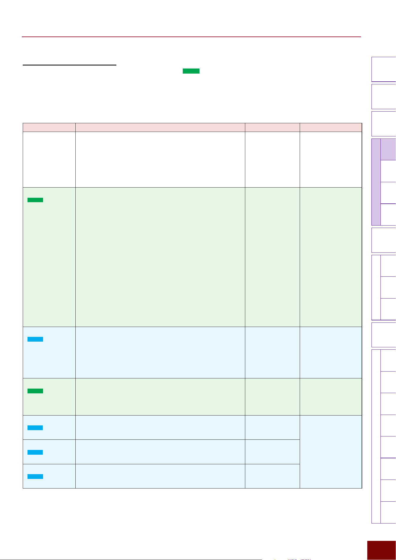
EAD50 EAD20 User Guide
109
Settings in Screens (Parameters)
Modifier
Knobs
LED
Rotary
Faders
[ MIC / TRIG ]
[ SCENE ][ CLICK ][ RECORDER ]
[ MENU ]
MicTriggerKitEffectRecorderLooperSamplingUtilityOutputAux In
USB AudioBluetooth
FileFactory
Reset
Version
[
LIVE SET
]
[F3] Setting "Mic "Mic In
Sets input sound-related settings for each mic jack. For the
EAD50
model, the mic jack is selected in a separate screen
displayed by pressing the [F1] MicSel button before specifying respective parameter settings.
NOTE
The mic jacks to which the setting is applied are displayed in the upper right area of the screen.
Page 1/4
Parameter Explanation Setting Default Value
On/Off For each mic jack, this sets whether to input sound from an
external source (On) or not (Off).
NOTE
This setting is linked to the lit/unlit status of channel on/off buttons 1
to 5 when the [MIC] button is lit.
Off, On They are always set
as indicated below for
Preset Scenes (Mic).
·Mic1: On
·Mic2: Off
·Mic3: Off
·Mic4: Off
·Mic5: Off
Phantom
(
EAD50
only)
Sets phantom power On/Off for each XLR connector of
the [MIC/LINE INPUT] jack. Set it to [On] for connecting a
condenser mic or other device that requires a phantom power
supply to the corresponding mic jack.
NOTE
To prevent noise when turning the phantom power On/Off, the mic
input is muted for a few seconds.
Phantom Power Precautions
Observe the following precautions in order to prevent damage
to this product and external devices or noise.
• Switch the phantom power On/Off with [MIC/TRIG] sliders
minimized.
• Do not connect/disconnect cables from mic jacks with the
phantom power left On.
• Leave the phantom power Off when not needed.
• Switch Off phantom power before connecting a device that
does not support phantom power to a mic jack.
Off, On They are always set
as indicated below for
Preset Scenes (Mic).
·Mic1: On
·Mic2: Off
·Mic3: Off
·Mic4: Off
·Mic5: Off
Pairing
(
EAD20
only)
Sets whether to set the L and R gain settings, for mic input
sounds from the included Sensor Unit, together (Paired) or
separately (Paired Exc Gain).
NOTE
To prevent noise when changing the gain setting, mic input is
muted for a few seconds.
Paired, Paired Exc
Gain
Setting value in Scene
(Mic)
Gain
(
EAD50
only)
This sets the input sound gain level for each mic jack.
NOTE
To prevent noise when changing the gain setting, mic input is
muted for a few seconds.
−12 – +50 Setting value in Scene
(Mic)
Gain L/R
(
EAD20
only)
Displayed if the Pairing setting is Paired. Sets the L/R and R
gain settings, for mic input sounds from the included Sensor
Unit, together (Paired).
−12 – +19 Setting value in Scene
(Mic)
Gain L
(
EAD20
only)
Displayed if the Pairing setting is Paired Exc Gain. Sets the
gain setting for the L mic input sound from the included Sensor
Unit.
−12 – +19
Gain R
(
EAD20
only)
Displayed if the Pairing setting is Paired Exc Gain. Sets the
gain setting for the R mic input sound from the included
Sensor Unit.
−12 – +19
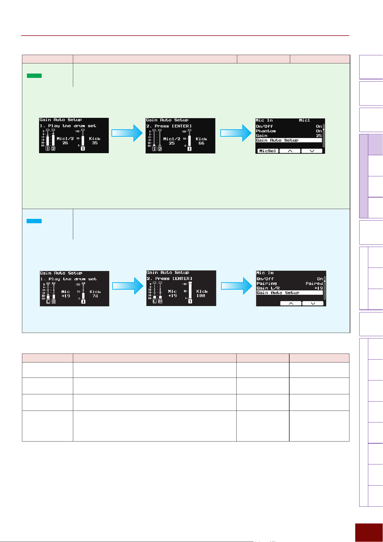
EAD50 EAD20 User Guide
110
Settings in Screens (Parameters)
Modifier
Knobs
LED
Rotary
Faders
[ MIC / TRIG ]
[ SCENE ][ CLICK ][ RECORDER ]
[ MENU ]
MicTriggerKitEffectRecorderLooperSamplingUtilityOutputAux In
USB AudioBluetooth
FileFactory
Reset
Version
[
LIVE SET
]
Parameter Explanation Setting Default Value
Gain Auto Setup
(
EAD50
)
This parameter is only enabled if the included DSU50 Sensor Unit is connected to the [MIC1], [MIC2], or [
q
KICK/
y
] jack on the product. Gain levels for mic sounds (Mic1 and Mic2) and Trigger sounds (Kick) are
adjusted automatically.
Gain Auto Setup
(
EAD20
)
This parameter is only enabled if the included DSU50 Sensor Unit is connected to both [TO SENSOR
UNIT] jacks on the product. This automatically adjusts the gain levels for mic sounds (Jack B) and Trigger
sounds (Jack A) input from the Sensor Unit.
Page 2/4
Parameter Explanation Setting Default Value
Volume This sets the volume of sounds input from each mic jack.
0 – 127 Setting value in Scene
(Mic)
Pan This sets the stereo position for sounds input via each mic
jack.
L63 – C – R63 Always set to “C” for
Preset Scenes (Mic).
Phase Sets whether to invert the phase of sounds input via each mic
jack (On) or not (Off).
Off, On Always set to “Off” for
Preset Scenes (Mic).
Delay This sets the delay level for sounds input via each mic jack.
If the distance between each mic and the tone generator
is different, this setting can correct for the audible delay
between different mics.
0.0 ms – 0.1 ms –
10.0 ms
(0.000 m – 0.034 m –
3.400 m)
Always set to “0 ms” for
Preset Scenes (Mic).
Gain is automatically adjusted inside this
product while drum performances are
continued. When automatic adjustments are
finished, the screen changes as shown next.
NOTE
• This function can be used even if a device other than a DSU50
sensor unit is connected, but it will not provide appropriate gain
values. Also, the screen in step 2 might not be displayed. Only
use this function if a DSU50 unit is connected.
• This function does not adjust levels at other mic jacks (MIC3,
MIC4, or MIC5).
1.
Press [ENTER] to display the Gain
Auto Setup Screen and then play
the drums.
2.
Press [ENTER] to confirm and apply the adjustment value.
The screen returns to displaying the previously displayed screen.
Gain is automatically adjusted inside this
product while drum performances are
continued. When automatic adjustments are
finished, the screen changes as shown next.
1.
Press [ENTER] to display the Gain
Auto Setup Screen and then play
the drums.
2.
Press [ENTER] to confirm and apply the adjustment value.
The screen returns to displaying the previously displayed screen.
EAD50 EAD20 User Guide
111
Settings in Screens (Parameters)
Modifier
Knobs
LED
Rotary
Faders
[ MIC / TRIG ]
[ SCENE ][ CLICK ][ RECORDER ]
[ MENU ]
MicTriggerKitEffectRecorderLooperSamplingUtilityOutputAux In
USB AudioBluetooth
FileFactory
Reset
Version
[
LIVE SET
]
Page 3/4
Parameter Explanation Setting Default Value
Gate Turns the gate function On/Off for each mic jack.
The “gate” function shuts off sound when it drops below a
specified volume value. Normally, the gate is left “open” when
Off and “closed” when On. It is used to prevent redundancy
between mics for different instruments or to filter the lingering
sound of tom or snare drums in order to adjust sound
duration.
Off, On Always set to “Off” for
Preset Scenes (Mic).
Gate Threshold For each mic jack, this sets the threshold volume level for
cutting off input sounds (close the gate). The gate will begin
closing when volume drops below this threshold value. Adjust
the values to filter out unwanted sound.
−73dB – −30dB Setting value in Scene
(Mic)
Gate Hold After a gate is opened, this specifies the minimum time the
gate is held open before it begins closing. Even if the volume
drops below the threshold level the gate will remain closed
until the specified time has elapsed, after which it will begin
closing.
0 ms – 500 ms
Gate Attack This setting specifies how long after the gate starts opening
(the volume starts gradually increasing) until the normal
volume level is restored.
0.02 ms – 40 ms
Gate Release This setting specifies how long after the gate starts closing
(volume starts decreasing) until the volume is fully muted.
10 ms – 680 ms
Page 4/4
Parameter Explanation Setting Default Value
Noise Gate This turns the gate function On/Off for each mic jack. Turn
this On if noise when muted is at a concerning level, such as
when mic gain is increased.
Off, On Always set to “Off” for
Preset Scenes (Mic).
Noise Gate Thr Sets the input level (threshold level) where the noise gate
effect starts being applied.
−90dB – −42dB Set to -68 dB for all
Preset Scenes (Mic).
Noise Gate Rel Sets the time until noise gate effects are no longer applied.
5 ms – 1400 ms Always set to “500 ms”
for Preset Scenes (Mic).
JackNoise
Reduction (
EAD20
only)
This reduces the noise generated, such as when the Sensor
Unit cable moves during performances.
On, Off Always set to “On” for
Preset Scenes (Mic).
EAD50 EAD20 User Guide
112
Settings in Screens (Parameters)
Modifier
Knobs
LED
Rotary
Faders
[ MIC / TRIG ]
[ SCENE ][ CLICK ][ RECORDER ]
[ MENU ]
MicTriggerKitEffectRecorderLooperSamplingUtilityOutputAux In
USB AudioBluetooth
FileFactory
Reset
Version
[
LIVE SET
]
Parameter Explanation Setting Default Value
Talk Mics connected to this product can not only be used to
capture drum performances, but also performer talking
sounds by switching to the Talk mode. This selects whether
to change the setting for connected mics to the mode for
capturing talk (On) or for capturing drum performances (Off).
Note that changing the setting will change all parameters in
the following screen and will be applied to all mics for talking.
[MIC/TRIG]
"
[F3] Setting
"
Mic In, Mic EQ, Mic TranComp, Mic Out
This setting results in the following being displayed in
respective mic setting screens ([MIC/TRIG]
"
[F3] Setting
"
Mic).
EAD50
If set to “On,” then the currently selected mic is displayed in
the upper right area of the screen, as “Mic1 Talk,” “Mic Talk2,”
and so on. If set to “Off,” then the currently selected mic is
displayed in the upper right area of the screen, as “Mic1,”
“Mic2,” and so on.
EAD20
If set to “On,” then “Talk” is displayed in the upper right area
of the screen. If set to “Off,” then “Talk” is not displayed in the
upper right area of the screen.
CAUTION
If the talk function is On, a variety of mic settings are changed
to values for talking. In particular, the talk function will
increase gain, so drum playing with talk set to On could cause
unexpectedly high volumes. Be extra careful to avoid playing
music with the talk setting On.
Off, On Always set to “Off” for
Preset Scenes (Mic).
[F3] Setting "Mic "Mic EQ
This product offers 4 EQ (equalizer) bands and high-pass filters that can be applied to input sound from each mic jack. In
this case, EQ-related settings are configured for each jack. For the
EAD50
model, the [F1] MicSel button is used to select the
mic jack before specifying corresponding settings. After selecting the type and color settings on the first page, more detailed
linked settings are set accordingly on the second and subsequent pages. After selecting the type and setting the color, more
detailed adjustments can be made using detailed settings on the second and subsequent pages.
NOTE
• The mic jacks to which the setting is applied are displayed in the upper right area of the screen.
• For more information about equalizers, refer to the diagrams on Page 32.
Page 1/6
Parameter Explanation Setting Default Value
On/Off This sets whether (On) or not (Off) to apply EQ to input
sounds
Off, On Always set to “On” for
Preset Scenes (Mic).
Type This selects the EQ type for each mic jack.
(Refer to the EQ Type
List.)
Setting value in Scene
(Mic)
Color This sets the EQ color (sound brightness) for each mic jack.
The larger the numeric value, the brighter the sound.
−64 – 0 – +63
EAD50 EAD20 User Guide
113
Settings in Screens (Parameters)
Modifier
Knobs
LED
Rotary
Faders
[ MIC / TRIG ]
[ SCENE ][ CLICK ][ RECORDER ]
[ MENU ]
MicTriggerKitEffectRecorderLooperSamplingUtilityOutputAux In
USB AudioBluetooth
FileFactory
Reset
Version
[
LIVE SET
]
Page 2/6
Parameter Explanation Setting Default Value
Low Freq This sets the midpoint of the EQ low frequency band for each
mic jack.
32Hz – 2.0kHz Setting value in Scene
(Mic)
Low Gain This sets the gain level for the EQ low frequency band for
each mic jack.
−12dB – 0dB –
+12dB
Low Q This sets the Q factor (frequency characteristics) for the EQ
low frequency band for each mic jack. If Low Shape is set to
LowShelving, then the Low Q value will have no effect.
0.1 – 12.0
Low Shape This selects the shape of frequency characteristics for the EQ
low frequency band.
LowShelving,
PeakDip
Page 3/6
Parameter Explanation Setting Default Value
MidLow Freq This sets the midpoint of the EQ low-to-mid frequency band
for each mic jack.
100Hz – 10.0kHz Setting value in Scene
(Mic)
MidLow Gain This sets the gain level for the EQ low-to-mid frequency band
for each mic jack.
−12dB – 0dB –
+12dB
MidLow Q This sets the Q factor (frequency characteristics) for the EQ
low-to-mid frequency band for each mic jack.
0.1 – 12.0
Page 4/6
Parameter Explanation Setting Default Value
MidHigh Freq This sets the midpoint of the EQ mid-to-high frequency band
for each mic jack.
100Hz – 10.0kHz Setting value in Scene
(Mic)
MidHigh Gain This sets the gain level for the EQ mid-to-high frequency band
for each mic jack.
−12dB – 0dB –
+12dB
MidHigh Q This sets the Q factor (frequency characteristics) for the EQ
mid-to-high frequency band for each mic jack.
0.1 – 12.0
Page 5/6
Parameter Explanation Setting Default Value
High Freq This sets the midpoint frequency of the EQ high frequency
band for each mic jack.
500Hz – 16.0kHz Setting value in Scene
(Mic)
High Gain This sets the gain for the EQ high frequency band for each
mic jack.
−12dB – 0dB –
+12dB
High Q This sets the Q factor (frequency characteristics) for the
EQ high frequency band for each mic jack. The larger the
setting value, the narrower the frequency range and the more
quickly tone characteristics change. The smaller the value,
the wider the frequency range and the more gradually tone
characteristics change.
If High Shape is set to HighShelving, then the High-Q value
has no effect.
0.1 – 12.0
High Shape This selects the shape of frequency characteristics for the EQ
high frequency band.
If LPF is selected, the entire equalizer changes to functioning
as a low-pass filter.
HighShelving,
PeakDip, LPF
Page 6/6
Parameter Explanation Setting Default Value
HPF Freq This sets the cutoff frequency of the high-pass filter for each
mic jack.
Thru, 56Hz –
2.0kHz
Setting value in Scene
(Mic)
HPF Q This sets the Q factor (frequency characteristics) for the high-
pass filter for each mic jack.
0.1 – 12.0
EAD50 EAD20 User Guide
114
Settings in Screens (Parameters)
Modifier
Knobs
LED
Rotary
Faders
[ MIC / TRIG ]
[ SCENE ][ CLICK ][ RECORDER ]
[ MENU ]
MicTriggerKitEffectRecorderLooperSamplingUtilityOutputAux In
USB AudioBluetooth
FileFactory
Reset
Version
[
LIVE SET
]
[F3] Setting "Mic "Mic TranComp
This adjusts the degree to which Transient Effects (attack or release) and Compressor Effects are applied to sound inputs for
each mic jack. The on/off status of both the Effects is switched simultaneously.
For the
EAD50
model, the [F1] MicSel button is used to select the mic jack before specifying corresponding settings. After
selecting the type and specifying the depth setting on the first page, more detailed parameter settings are configured
automatically on the second and subsequent pages. After selecting the type and setting the depth, more detailed adjustments
can be made using detailed setting parameters on the second and subsequent pages.
Page 1/3
Parameter Explanation Setting Default Value
On/Off This sets whether (On) or not (Off) Transient Compressor
Effects are applied to input sounds for each mic jack.
Off, On Always set to “On” for
Preset Scenes (Mic).
Type This selects the Transient Compressor type for each mic jack.
(Refer to the Type
List.)
Setting value in Scene
(Mic)
Depth This adjusts the level of Transient Compressor Effects applied
to each mic jack.
0 – 127
Page 2/3
Parameter Explanation Setting Default Value
Tran Attack This adjusts the attack effect applied to input sounds for each
mic jack.
−50 – 0 – +50 Setting value in Scene
(Mic)
Tran Release This sets the release effect applied to input sounds from each
mic jack.
−50 – 0 – +50
Tran Sensitivity For each mic jack, this adjusts the sensitivity for applying
Transient Effects based on how hard the drum is hit.
1 – 4
Page 3/3
Parameter Explanation Setting Default Value
Comp Threshold This specifies the input level (threshold level) where
Compressor effects begin being applied to each mic jack.
−48dB – −6dB Setting value in Scene
(Mic)
Comp Ratio This sets how much the portion of sounds that exceeds the
threshold value are compressed for each mic jack. The larger
the setting value, the greater the compression applied.
1.0, 1.5, 2.0, 3.0, 4.0,
5.0, 7.0, 10.0, 20.0
Comp Attack This sets how long it takes to reach maximum Compressor
effects after the input level exceeds the threshold value for
each mic jack.
1 ms – 40 ms
Comp Release This sets how long it takes for Compressor effects to cease
after the input level drops below the threshold value for each
mic jack.
10 ms – 680 ms
Comp Out Level This specifies the compressor output level for each mic jack.
−18.0dB – 0.0dB –
+18.0dB
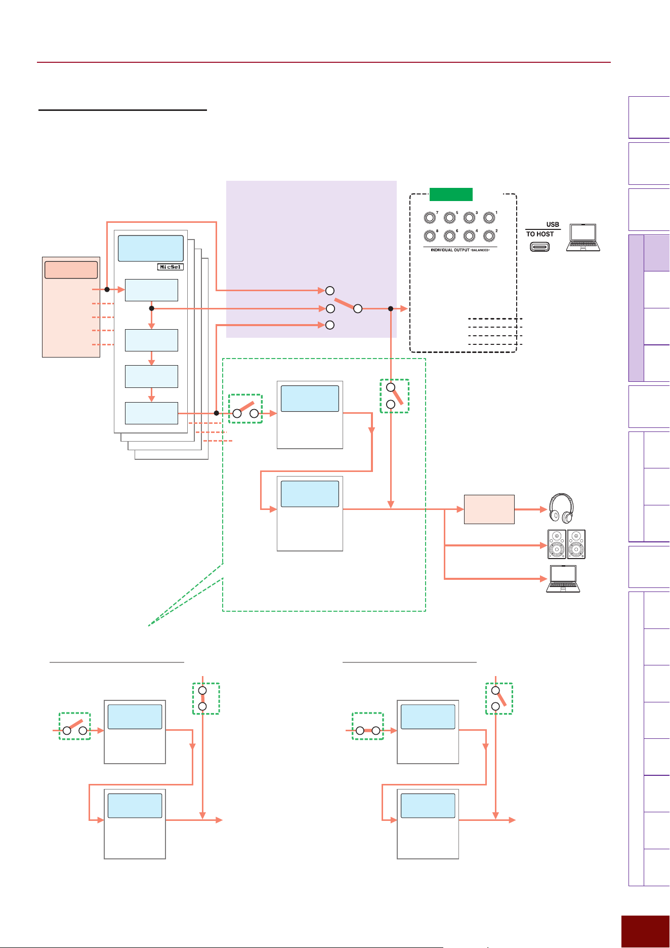
EAD50 EAD20 User Guide
115
Settings in Screens (Parameters)
Modifier
Knobs
LED
Rotary
Faders
[ MIC / TRIG ]
[ SCENE ][ CLICK ][ RECORDER ]
[ MENU ]
MicTriggerKitEffectRecorderLooperSamplingUtilityOutputAux In
USB AudioBluetooth
FileFactory
Reset
Version
[
LIVE SET
]
[F3] Setting "Mic "Mic Out
This specifies the route for sending input sounds from each mic jack to external outputs.
Switching routes using Effect Thru settings for each mic
Route for mic sound with Effect Thru*** = Off
(with System Effects/Master Effects applied)
A
B
A: On
B: Off
System
Effects
Master
Effects
• Reverb
• FX1
• FX2
• Master FX
• Master
Compressor
• Master EQ
[MIC/TRIG]
"
[F3] Setting
"
Effect
[MIC/TRIG]
"
[F3] Setting
"
Effect
Whether or not to output
sound to respective output
destinations (Phones, Main
Out, or USB Audio Out 1/2)
cannot be specified for each
mic
Route for mic sound with Effect Thru*** = On
(without System Effects or Master Effects applied)
A
B
A: Off
B: On
System
Effects
Master
Effects
• Reverb
• FX1
• FX2
• Master FX
• Master
Compressor
• Master EQ
[MIC/TRIG]
"
[F3] Setting
"
Effect
[MIC/TRIG]
"
[F3] Setting
"
Effect
Whether or not to output
sound to respective output
destinations (Phones, Main
Out, or USB Audio Out 1/2)
can be specified for each
mic
****
A
B
Effects Process Flow Diagram (Page 28): Detailed Diagram
of Mic Input Channels
Acoustic Drum
Section*
Mic Input 1
Mic Input 4
Mic Input 2
Mic Input 5
Mic Input 3
Mic-Specific
Effects
Parts EQ
Transient
Compressor
Insertion Effect1
Insertion Effect2
Branching Point for Extracting
Sound from Individual Mics
Any of the following three branching points
can be used to extract sound that has not
had System Effects or Master Effects applied
and adjust it individually with separate
devices, regardless of Effect Thru** settings.
If EQ Tran Thru =
• If EQ Thru
***
• If Tran Thru
• If Off
System
Effects
Master
Effects
• Reverb
• FX1
• FX2
• Master FX
• Master
Compressor
• Master EQ
Phones
EQ
[OUTPUT] jacks
(Main Out)
[MENU]
"
Output
"
Phones EQ
[USB TO HOST] terminal
(USB Audio Out 1/2)
[MIC/TRIG]
"
[F3] Setting
"
Mic
"
Mic Out
"
IndivOut
[INDIVIDUAL OUTPUT] jacks
• IndivOut 1/2
• IndivOut 3/4
• IndivOut 5/6
• IndivOut 7/8
All USB audio channels
will conform to IndvOut
settings.
[USB TO HOST] terminal
• USB Audio Out 3/4
• USB Audio Out 5/6
• USB Audio Out 7/8
• USB Audio Out 9/10
[MIC/TRIG]
"
[F3] Setting
"
Effect
[MIC/TRIG]
"
[F3] Setting
"
Effect
EAD50
Only
*
The EAD50 is
equipped with 5 mic
input channels.
The EAD20 has only 1
channel.
NOTE
USB Audio Out 1/2 = Main Out L/R
Whether or not to output mic and
Trigger sounds, with System Effects
and Master Effects applied, to
respective output destinations can be
specified
**
NOTE
It is also possible to extract only the return sound from
System Effects. For more information, refer to Page 28.
**
[MIC/TRIG]
"
[F3] Setting
"
Effect
"
Effect Out
"
Main Out
"
Phones Out, USB Audio Out 1/2
***
[MIC/TRIG]
"
[F3] Setting
"
Mic
"
Mic Out
"
Effect Thru
****
[MIC/TRIG]
"
[F3] Setting
"
Mic
"
Mic Out
"
Phones Out, Main Out, USB Audio Out 1/2
Effects Applied to All Mics
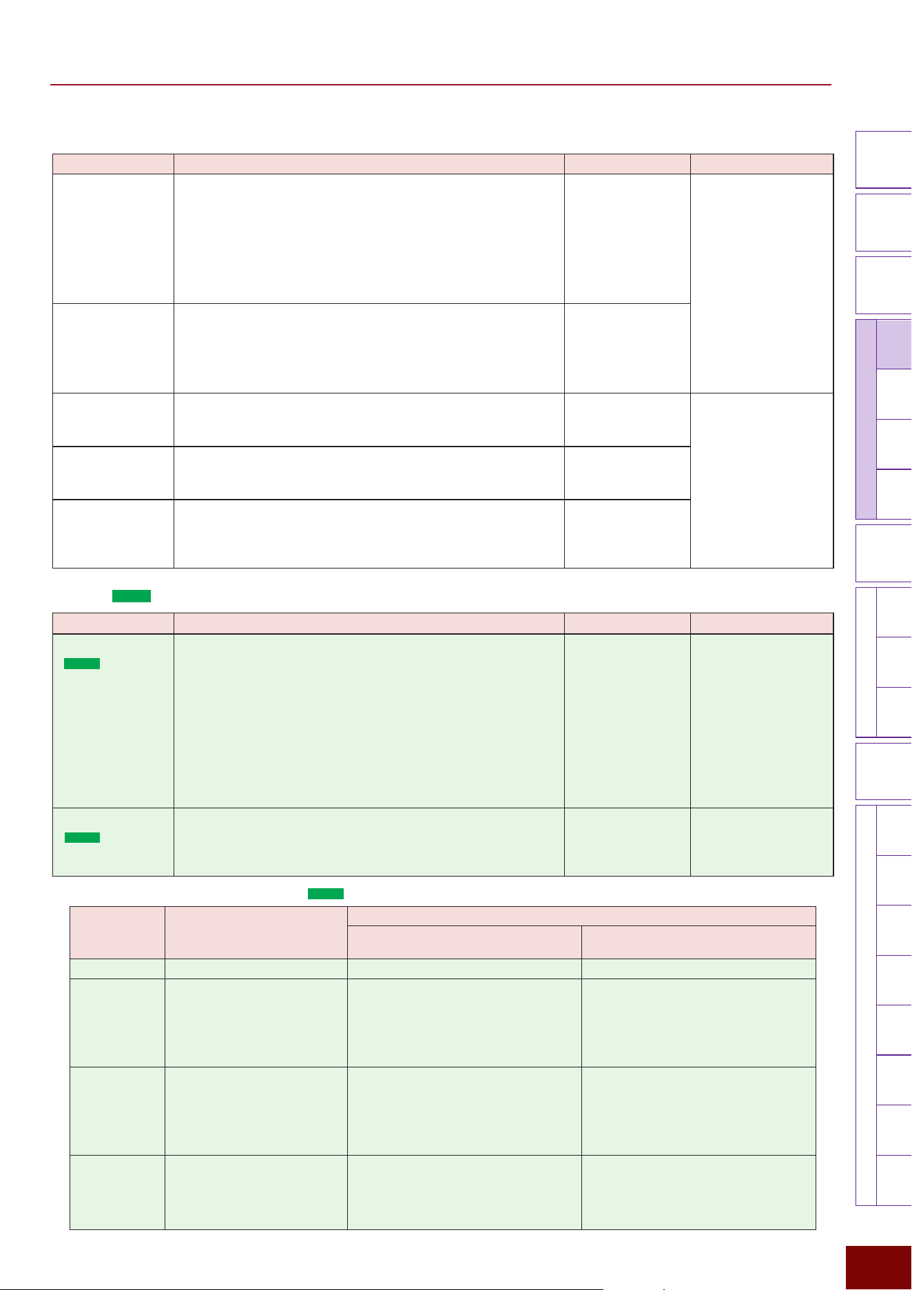
EAD50 EAD20 User Guide
116
Settings in Screens (Parameters)
Modifier
Knobs
LED
Rotary
Faders
[ MIC / TRIG ]
[ SCENE ][ CLICK ][ RECORDER ]
[ MENU ]
MicTriggerKitEffectRecorderLooperSamplingUtilityOutputAux In
USB AudioBluetooth
FileFactory
Reset
Version
[
LIVE SET
]
Page 1/2
Parameter Explanation Setting Default Value
EQ Tran Thru Sounds input via a mic jack can be extracted
via a branch point midway along the effects flow line in order
to output the sound via a separate jack without applying the
downstream Effects. This setting sets the branch point where
the sound is extracted.
• Off: Branches before applying System Effects.
• EQ Thru: Branches before starting part EQ.
• Tran Thru: Branches before applying Transient Compressor.
Off, EQ Thru,
Tran Thru
Always set to “Off” for
Preset Scenes (Mic).
Effect Thru
This specifies whether to pass input sounds from each mic
jack through the System Effects and Master Effects sections
(Off) or not (On). If On is selected, sound from the branching
point selected by EQ Tran Thru is routed to a point after the
Master Effects section.
Off, On
Main Out
This is only displayed if the Effect Through setting is On. This
individually sets whether sound from the branching point selected
in EQ Tran Thru is output from an [OUTPUT] jack (On) or not (Off).
Off, On Always set to “On” for
Preset Scenes (Mic).
Phones Out
This is only displayed if the Effect Through setting is On. This
individually sets whether sound from the branching point selected
in EQ Tran Thru is output from an [PHONES] jack (On) or not (Off).
Off, On
USB Audio Out
1/2
This is only displayed if the Effect Through setting is On. This
individually sets whether sound from the branching point
selected in EQ Tran Thru is output from an [USB TO HOST]
terminal (On) or not (Off).
Off, On
Page 2/2 (
EAD50
)
Parameter Explanation Setting Default Value
IndivOut
(
EAD50
only)
Input sounds from each mic jack can be diverted from the
effects process flow diagram at branching points and output
separately for each jack or channel.
This sets the [INDIVIDUAL OUTPUT] jack for outputting
performance sounds input from each mic jack.
NOTE
IndivOut1–8 settings are linked to USB Audio Out3–10 settings. For
example, if Mic1 = L1 + R2 is specified, then Mic1 sound output to
a computer via USB Audio 3/4 ports.
Off, L1+R2, L3+R4,
L5+R6, L7+R8,
L1, R2, L3, R4, L5,
R6, L7, R8, (L+R)1,
(L+R)2, (L+R)3,
(L+R)4, (L+R)5,
(L+R)6, (L+R)7,
(L+R)8
* For a description of
respective setting
values, refer to the
table below.
Always set to “Off” for
Preset Scenes (Mic).
IndivOut Vol
(
EAD50
only)
For sounds input from each mic jack, this adjusts the volume of
performance sounds output from branching points (Page 115)
in the Effects process flow diagram. If Variable is specified, the
volume is linked to [MIC/TRIG] slider operations.
Variable, 1 – 127 Always set to “Variable”
for Preset Scenes (Mic).
Respective IndivOut setting values (
EAD50
)
Setting Value
Comments
Connector Where Audio is Actually Output
INDIVIDUAL OUTPUT
–BALANCED–
USB TO HOST
Off Audio is not output. – –
L1+R2, L3+R4,
L5+R6, L7+R8
These settings will result in stereo
output via 2 jacks.
The numbers in setting values indicate the
jack number. For example, the setting “L1+R2”
indicates the following.
• Stereo L: Jack [1]
• Stereo R: Jack [2]
The numbers 1 – 8 in setting values indicate
corresponding USB Audio Out channels 3 – 10.
For example, the setting “L1+R2” indicates the
following.
• Stereo L: USB Audio Out 3
• Stereo R: USB Audio Out 4
L1, R2, L3, R4,
L5, R6, L7, R8
These settings result in monaural
output via only the L or R stereo
channel.
The numbers in setting values indicate the
jack number. For example, if set to “L1”, stereo
channel L is output via jack [1], but stereo
channel R is not output.
The numbers 1 – 8 in setting values indicate
corresponding USB Audio Out channels 3 – 10.
For example, the “L1” setting results in only the L
stereo channel being output from USB Audio Out
3. The “R2” setting results in only the R stereo
channel being output from USB Audio Out 4.
(L+R)1, (L+R)2,
(L+R)3, (L+R)4,
(L+R)5, (L+R)6,
(L+R)7, (L+R)8
These settings result in outputting
a mixture of stereo L and R audio
channels via one jack.
The numbers in setting values indicate the jack
number. For example, if set to “(L+R)1”, both L
and R channels are output via jack [1].
The numbers 1 – 8 in setting values indicate
corresponding USB Audio Out channels 3 – 10.
For example, if set to “(L+R)1”, then a mixture
of stereo L and R audio channels is output via
USB Audio Out 3.
EAD50 EAD20 User Guide
117
Settings in Screens (Parameters)
Modifier
Knobs
LED
Rotary
Faders
[ MIC / TRIG ]
[ SCENE ][ CLICK ][ RECORDER ]
[ MENU ]
MicTriggerKitEffectRecorderLooperSamplingUtilityOutputAux In
USB AudioBluetooth
FileFactory
Reset
Version
[
LIVE SET
]
Page 2/2 (
EAD20
)
Parameter Explanation Setting Default Value
USB AudOut
(
EAD20
only)
Mic input sounds from the Sensor Unit can be extracted at
the branching points (Page 115) in the effects process flow
diagram and output separately via USB audio channels 3 to 8.
This setting sets which USB channel to use.
Off, L3+R4, L5+R6,
L7+R8, L9+R10, L3,
R4, L5, R6, L7, R8,
L9, R10, (L+R)3,
(L+R)4, (L+R)5,
(L+R)6, (L+R)7,
(L+R)8, (L+R)9,
(L+R)10
* For a description of
respective setting
values, refer to the
table below.
Always set to “Off” for
Preset Scenes (Mic).
USB AudOut Vol
(
EAD20
only)
For mic input sounds from the Sensor Unit, this adjusts the
volume of sounds output from branching points (Page 115)
in the Effects process flow diagram. If “Variable” is specified,
the volume is linked to [MASTER] slider operations.
Variable, 1 – 127 Always set to “Variable”
for Preset Scenes (Mic).
Respective USB AudOut setting values (
EAD20
)
Setting Value
Comments
Off Audio is not output.
L3+R4, L5+R6, L7+R8, L9+R10 These settings result in stereo output via 2 channels.
L3, R4, L5, R6, L7, R8, R9, R10 These settings result in monaural output via only the L or R stereo channel.
(L+R)3, (L+R)4, (L+R)5, (L+R)6, (L+R)7,
(L+R)8, (L+R)9, (L+R)10
These settings result in a mixture of L and R stereo audio sound being
output via one channel.
EAD50 EAD20 User Guide
118
Settings in Screens (Parameters)
Modifier
Knobs
LED
Rotary
Faders
[ MIC / TRIG ]
[ SCENE ][ CLICK ][ RECORDER ]
[ MENU ]
MicTriggerKitEffectRecorderLooperSamplingUtilityOutputAux In
USB AudioBluetooth
FileFactory
Reset
Version
[
LIVE SET
]
[F3] Setting
"
Trigger
This specifies how to process signals input from a Trigger or Foot Switch jack and produce or output electronic sounds (Voices).
All settings are registered in Scenes as [Triggers].
[F3] Setting "Trigger "Trig Pairing
This sets whether to pair (paired) the two inputs from the two Trigger Input jacks marked with two digits (two monaural inputs)
or not pair (separate) the inputs.
Paired
Specify the Paired setting if the two Trigger signal inputs are both obtained from the same pad. This setting assumes two single
pads are connected 1-to-1.
Separate
Specify the Separate setting if the two Trigger signal inputs are obtained from separate pads. This setting assumes the two
pads are connected by a Y-cable or one is connected to a KP series pad that is in turn connected to a separate pad via a [PAD
INPUT] connector.
Parameter Explanation Setting Default Value
Kick/Trig6 This selects the input method to the [
q
KICK/
y
] jack.
It assumes a cable from the included sensor unit or a
KP series electronic drum kick pad (1-zone pad) will be
connected to the [
q
KICK/
y
] jack and the default setting is
Separate. If connecting to a non-KP series pad, change the
settings based on the number of zones in the connected pad.
Separate, Paired Setting value in Scene
(Trigger)
Snare/Trig7 This selects the input method to the [
w
SNARE/
u
] jack.
It assumes a cable from a drum Trigger is connected to the [
w
SNARE/
u
] jack and the default setting is Paired.
Separate, Paired
Trig3/Trig8 This selects the input method to the [
e
/
i
] jack.
Separate, Paired
Trig4/Trig9 This selects the input method to the [
r
/
o
] jack.
Separate, Paired
Trig5/Trig10
(
EAD50
only)
This selects the input method to the [
t
/
!0
] jack.
Separate, Paired Setting value in Scene
(Trigger)
EAD50 EAD20 User Guide
119
Settings in Screens (Parameters)
Modifier
Knobs
LED
Rotary
Faders
[ MIC / TRIG ]
[ SCENE ][ CLICK ][ RECORDER ]
[ MENU ]
MicTriggerKitEffectRecorderLooperSamplingUtilityOutputAux In
USB AudioBluetooth
FileFactory
Reset
Version
[
LIVE SET
]
[F3] Setting "Trigger "Trig In
This specifies how to process Trigger signals input from this product.
[F3] Setting "Trigger "Trig In "Pad
This setting is for pads that send Trigger Input signals to this product. Electronic drums can include a variety of pads with
different characteristics, such as kick, snare, tom, cymbal, hi-hat, and drum Trigger pads. This product includes groups of
settings optimized for the characteristics of each pad type. Select the group that is best for each pad (and each Trigger Input).
Settings are configured by pressing the [F1] button to select the Trigger Input (or pad) and then specifying corresponding
settings.
NOTE
Settings Trig6 and thereafter are enabled only when the Trig Pairing is set to “Separate.”
Page 1/5
Parameter Explanation Setting Default Value
Category Selects the pad type category.
Off, Kick, Snare, Tom,
Cymbal, HH, Others
Setting value in Scene
(Trigger)
Type Selects the specific model number as the pad type.
Depending on the
firmware version
Page 2/5
Parameter Explanation Setting Default Value
Gain This sets the gain (amplification) level for signals input when a
pad is hit.
NOTE
If the setting is set high, all input signals above a certain level
(maximum level) will be treated as the same. However, the setting
can be corrected for the hitting force variability error. Setting a low
value will broaden expressive by making it easier to reflect the
hitting force variations in sounds.
1 – 127 Set to the pad type
appropriate for the
Preset Scene (Trigger).
Rim Gain If a multi-piezo pad is connected, such as the XP125SD-X,
this sets the gain level for the rim area. It is available only
when the Trig Pairing is set to “Paired.”
1 – 127
H/R Balance If a multi-piezo pad, such as the XP125SD-X is connected,
this sets balance between the head and rim areas. If a head
sound is produced when the rim is hit, increasing the rim (R)
value will make it easier to produce rim sounds. Similarly, if a
rim sound is produced when the head is hit, increasing the
head (H) value will make it easier to produce head sounds. If
two monaural input jacks are used, the parameter is available
only when the Trig Pairing is set to “Paired.”
H49 – H1, H = R,
R1 – R49
Gain Auto Setup Same as the parameter with the same name in [MIC/TRIG]
"
Mic
"
Mic In settings. Refer to Page 110.
EAD50 EAD20 User Guide
120
Settings in Screens (Parameters)
Modifier
Knobs
LED
Rotary
Faders
[ MIC / TRIG ]
[ SCENE ][ CLICK ][ RECORDER ]
[ MENU ]
MicTriggerKitEffectRecorderLooperSamplingUtilityOutputAux In
USB AudioBluetooth
FileFactory
Reset
Version
[
LIVE SET
]
Page 3/5
Parameter Explanation Setting Default Value
Wait Time This sets how long to wait before detecting the Trigger signal
from the corresponding pad. Adjust this parameter so that
the Trigger signal is recognized when its level reaches the
maximum, resulting that the sound is produced with the force
corresponding to your hitting one.
1 ms – 64 ms Set to the pad type
appropriate for the
Preset Scene (Trigger).
Reject Time Trigger signals generated from a series of hits during this time
are ignored.
NOTE
Even within the reject period, if the sound level from a second hit
is at least double the sound level of the first hit, then the sound is
expressed instead of being rejected.
4 ms – 500 ms
Sensitivity This sets the sensitivity level based on a series of pad hits.
1 – 13
Page 4/5
Parameter Explanation Setting Default Value
Min Level
Max Level
This sets the Trigger Input signal levels used to output velocity
values, between minimum (%) and maximum (%). No sound is
produced for Trigger signals less than or equal to the minimum
level specified here. Trigger signal values greater than or equal
to the maximum level specified here are assigned the maximum
velocity value specified by the Min Velocity/Max Velocity
parameters below.
1 – 100 Set to the pad type
appropriate for the
Preset Scene (Trigger).
Min Velocity
Max Velocity
This sets velocity values in term of a minimum to maximum
range based on the Trigger Input signal levels specified by
Min Level/Max Level settings above. Sound is produced
based on the velocity range specified here.
1 – 127
Page 5/5
Parameter Explanation Setting Default Value
Xstick On/Off This setting is enabled only for jacks with a multi-piezo pad
connected. If set to On, the open rim shot and closed rim shot
sounds are switched depending on how hard the pad is hit.
NOTE
• If the Xstick On/Off setting is Off, an open rim shot sound is
always produced.
• If a single-piezo pad is connected, it has no effect.
Off, On Set to the pad type
appropriate for the
Preset Scene (Trigger).
Xstick Adjust This setting is enabled only for jacks with a multi-piezo pad
connected. If the Xstick On/Off setting is set to On, the ease
of switching between Xstick and open rim shots by hitting the
rim of a multi-piezo pad can be adjusted. Increasing the value
will make it easier to produce Xstick sounds when pads are
hit hard, whereas decreasing the value will make it easier to
produce open rim shot sounds even by hitting lightly.
1 – 127
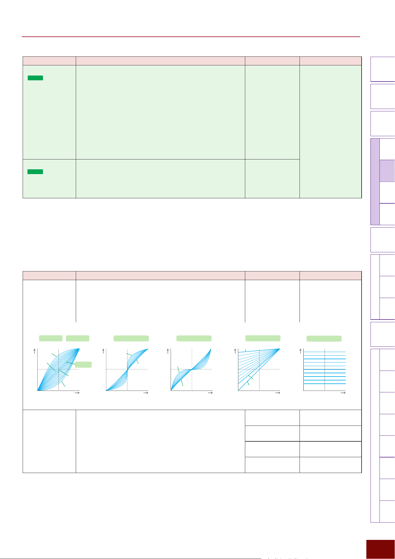
EAD50 EAD20 User Guide
121
Settings in Screens (Parameters)
Modifier
Knobs
LED
Rotary
Faders
[ MIC / TRIG ]
[ SCENE ][ CLICK ][ RECORDER ]
[ MENU ]
MicTriggerKitEffectRecorderLooperSamplingUtilityOutputAux In
USB AudioBluetooth
FileFactory
Reset
Version
[
LIVE SET
]
Parameter Explanation Setting Default Value
Position
(
EAD50
only)
This setting is only enabled for Trig3 – Trig5. It sets whether to
use the pad position detection function (On) or not use it (Off).
If set to On, the tone characteristics can be varied depending
on where the pad is hit. The setting is only enabled when a
pad with position detection functionality is connected and
a Voice that supports the position detection functionality is
assigned to the pad Inst.
NOTE
For a list of pads with position detection functionality, refer to the Pad
Module Compatibility Table. For a list of Voices that support position
detection functionality, refer to the Voice List in Data List. Both are
available for download from the Yamaha website (Page 4).
Off, On Set to the pad type
appropriate for the
Preset Scene (Trigger).
Attenuator
(
EAD50
only)
This parameter is only enabled for Trig3 – Trig5 or Trig8 –
Trig10. It sets whether to let Trigger signals attenuate (On) or
not (Off). Normally, setting to Off is not a problem, but if the
input level does not match the pad, such as when connected
to a non-Yamaha pad, try setting it to On.
Off, On
[F3] Setting "Trigger "Trig In "Vel Curve
This selects, for each pad (each Trigger Input), the method used (velocity curve) to vary the sound level (velocity) in response
to variations in the input signal produced by hitting a pad.
Settings are configured by pressing the [F1] button to select the Trigger Input (or pad) and then specifying corresponding
settings.
Parameter Explanation Setting Default Value
Curve This selects the velocity curve.
Normal,
Hard1–10,
Loud1–10,
Spline A1–10, Spline
B1–10, Offset1–10,
Fix1–10, Custom
Always set to Normal for
Preset Scenes (Trigger).
Loud1
‒
10
Hard1
‒
10
Normal
Spline A1
‒A
10 Spline B1
‒B
10
Offset1
‒Offset
10
Fix1
‒Fix10
Offset10
Offset1
Normal
Spline B1
Spline B10
Hard10
Spline A1
Spline A10
Fix1
Fix10
Loud10
Fix6
Hard1
Loud1
Trigger Input Level Trigger Input Level Trigger Input Level Trigger Input Level Trigger Input Level
Velocity
Velocity
Velocity
Velocity
Velocity
• If Custom is
Selected
X1
Y1
X2
Y2
Displayed when Custom is selected as the velocity curve.
A line graph can be created by specifying 2 coordinate points
(X1-Y1 and X2-Y2).
1 – 126 Always set to 32 for
Preset Scenes (Trigger).
1 – 127 Always set to 32 for
Preset Scenes (Trigger).
2 – 127 Always set to 96 for
Preset Scenes (Trigger).
1 – 127 Always set to 96 for
Preset Scenes (Trigger).
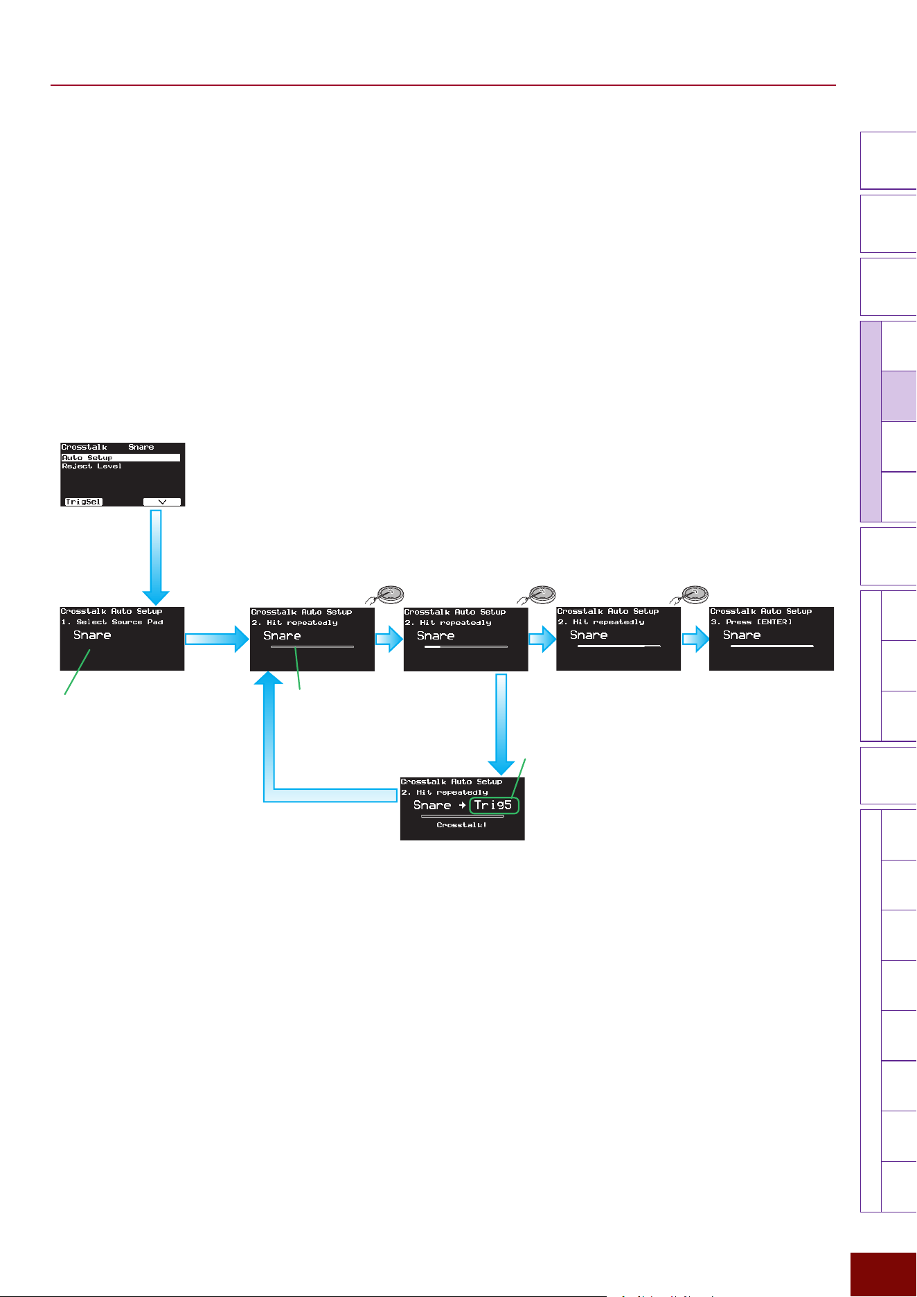
EAD50 EAD20 User Guide
122
Settings in Screens (Parameters)
Modifier
Knobs
LED
Rotary
Faders
[ MIC / TRIG ]
[ SCENE ][ CLICK ][ RECORDER ]
[ MENU ]
MicTriggerKitEffectRecorderLooperSamplingUtilityOutputAux In
USB AudioBluetooth
FileFactory
Reset
Version
[
LIVE SET
]
[F3] Setting "Trigger "Trig In "Crosstalk
The term “crosstalk” refers to Trigger signals generated from other pads, due to resonance or interference between different
pads, when an electronic drum pad is hit (including from acoustic drums with a drum Trigger attached). This setting is used
to prevent each pad from becoming a source of crosstalk by specifying maximum values for each pad that do not generate
Trigger signals. Settings can be configured by hitting each pad (Auto Setup) or by entering values (Reject Level). Try using
Auto Setup first and then, if crosstalk is still generated, directly enter setting values (Reject Level) for each pad.
NOTE
In Preset Scenes, the initial Reject Level setting is always set high. If an electronic drum pad or Trigger sensor is installed in the drum set, it
is recommended to execute Auto Setup for each Trigger Input (pads and Trigger sensors) before playing.
[F3] Setting "Trigger "Trig In "Crosstalk "Auto Setup (automatic setting for preventing crosstalk)
This setting is used to set maximum Trigger signal levels (Reject Levels) by hitting a specific pad to determine the maximum
Trigger signal level for that pad that does not result in generating crosstalk.
[ENTER] button
[ENTER]
button
1.
Use the [+]/[-] buttons or
knob to select the Trigger
Input to which the setting
will be applied (Trigger Input
being configured to prevent a
crosstalk generation source).
After selecting the input, press
[ENTER] to advance to the
next screen.
Progress bar
If crosstalk is generated, a
screen showing the Trigger Input
that generated the crosstalk is
displayed. This example shows
the snare pad is generating
crosstalk with respect to Trig5.
3.
When the progress bar reaches
100%, press [ENTER] to display the
original screen again. That confirms
and applies the final Reject Level
from step 2.
Trigger Input that
generated the crosstalk
At this point, the location corresponding to
the Reject Level value that prevents crosstalk
from occurring again, is tentatively updated
(to the Trig5 value in the screenshot shown).
That resets the number of hits
to zero, so repeat step 2 from
the beginning.
2.
Repeatedly hit the Trigger Input selected in step 1.
If no crosstalk occurs in response to hitting the pad, the progress bar will
advance as shown, based on the number of times the pad was hit.
NOTE
• To ensure the correct setting, hit the pad in step 2 in a
variety of places with various levels of force.
• In step 2, if a pad other than the one selected in step 1
was hit or selecting a different pad is desired, press the
[EXIT] button and start over from step 1.
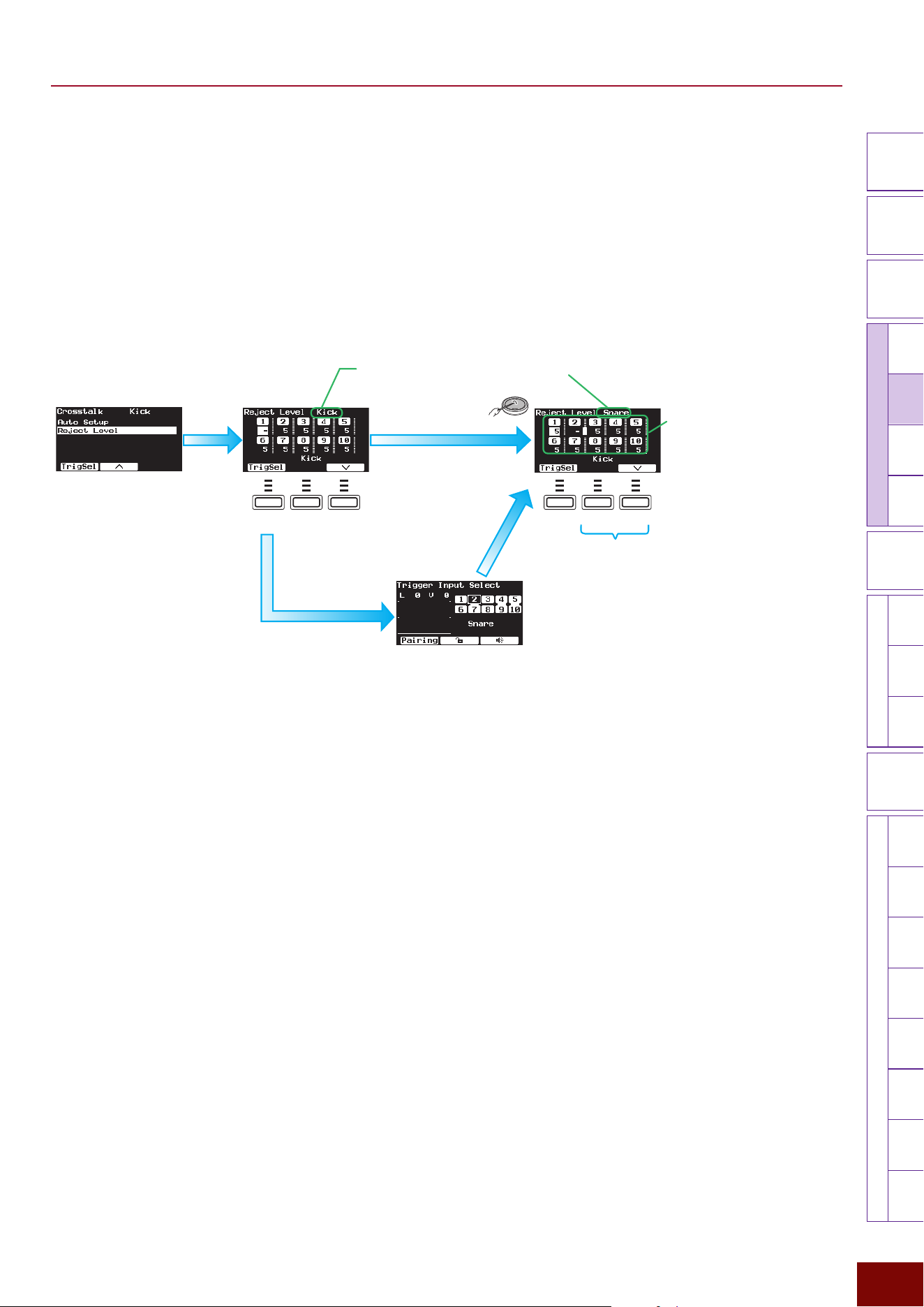
EAD50 EAD20 User Guide
123
Settings in Screens (Parameters)
Modifier
Knobs
LED
Rotary
Faders
[ MIC / TRIG ]
[ SCENE ][ CLICK ][ RECORDER ]
[ MENU ]
MicTriggerKitEffectRecorderLooperSamplingUtilityOutputAux In
USB AudioBluetooth
FileFactory
Reset
Version
[
LIVE SET
]
[F3] Setting "Trigger "Trig In "Crosstalk "Reject Level (manual setting for preventing crosstalk)
This setting is used to resolve crosstalk between the pad displayed in the upper right of the screen (from which crosstalk is
being generated) and any other pad (where crosstalk is occurring). For example, if hitting the snare incorrectly produces a
sound from the Kick pad, hit the snare pad to display “Snare” in the upper right of the screen. Then, move the cursor to “1” (Kick)
and increase the Reject Level. That will prevent output of a Trigger signal sound from the kick that is below the specified value.
While higher values are better at preventing crosstalk, they can also make it more difficult to produce sound from other pads at
the same time.
Setting
0 – 99
(If crosstalk is generated by and occurs at the same pad, “–” is displayed.)
F1 F2 F3 F1 F2 F3
NOTE
• The figure shows screens from model EAD50. The “10” is not included in EAD20
screens.
[ENTER]
button
1.
Hit the corresponding
pad to select the
Trigger Input for
applying the setting.
Trigger Input that possibly generated the crosstalk (for applying the setting)
The Trigger Input can also be selected in
the Trigger Input Selection screen.
2.
Use the [F2]/[F3] buttons to move the
cursor to each Trigger Input setting
value (Reject Level).
[EXIT]
button
3.
For each Trigger Input with the
setting not being set, individually
specify a minimum (Reject Level)
value that does not result in
outputting a Trigger signal.
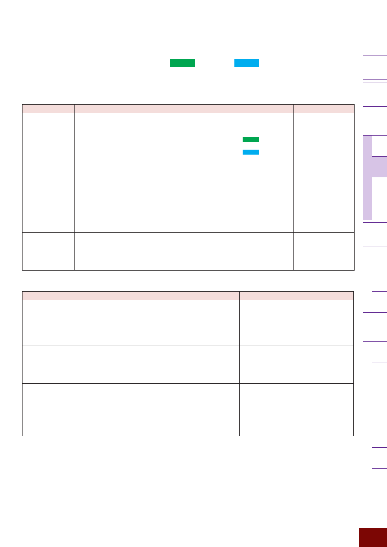
EAD50 EAD20 User Guide
124
Settings in Screens (Parameters)
Modifier
Knobs
LED
Rotary
Faders
[ MIC / TRIG ]
[ SCENE ][ CLICK ][ RECORDER ]
[ MENU ]
MicTriggerKitEffectRecorderLooperSamplingUtilityOutputAux In
USB AudioBluetooth
FileFactory
Reset
Version
[
LIVE SET
]
[F3] Setting "Trigger "Trig In "Foot Sw1 (
EAD50
), Foot Sw (
EAD20
)
A Trigger signal can be generated by pressing a separately sold foot switch (pedal) connected to the [FOOT SW1] jack. In
combination with a pad, it can also be used as a hi-hat.
Page 1/2
Parameter Explanation Setting Default Value
Type This selects the model connected to the foot switch jack.
FC3A, FC4A/5,
FC7, HH40, HH65,
RHH135
Always set to HH65 for
Preset Scenes (Trigger).
HH Trig In This selects the pad (Trigger Input signal) to be controlled by
the device connected to the foot switch jack. If a setting other
than Off is selected, an HH (hi-hat cymbal) can be played
in combination with a foot switch (pedal) connected to the
selected pad. If Off is selected, operating the foot switch
alone will play the Voice for FOOT SW1. For more information,
refer to Page 24.
EAD50
: Off, Kick,
Snare, Trig3–10
EAD20
: Off, Kick,
Snare, Trig3–9
Setting value in Scene
(Trigger)
HH Pitch Up
This setting is displayed and can be set if HH Trig In is set to
anything other than Off.
This specifies whether to raise the pitch of the Voice currently
being sounded (On) or not (Off) when the device connected
to the foot switch jack is fully pressed. This setting is valid
only if the currently-selected Voice is in the “HiHat1” category.
Off, On Always set to On for
Preset Scenes (Trigger).
HH Clutch Pos
This setting is displayed and can be set if HH Trig In is set to
anything other than Off.
Achieves the benefit of adjusting the hi-hat clutch position.
The smaller the setting value, the faster the attenuation of the
open hi-hat sound.
−32 – 0 – +32 Always set to 0 for
Preset Scenes (Trigger).
Page 2/2
Parameter Explanation Setting Default Value
Foot Close Pos
This setting is displayed and can be set if HH Trig In is set to
anything other than Off.
It adjusts the position where the hi-hat changes from an
open sound to a closed sound when the device connected
to the foot switch jack is pressed. The smaller the value, the
narrower the opening between the top and bottom cymbals.
–32 – 0 Always set to 0 for
Preset Scenes (Trigger).
Foot Close Vel
This setting is displayed and can be set if HH Trig In is set to
anything other than Off.
Selects whether to vary the velocity generated (variable)
by pressing the device connected to the foot switch jack or
specify a fixed value (1 – 127).
Variable, 1 – 127
Always set to “Variable”
for Preset Scenes
(Trigger).
Foot Splash Sens
This setting is displayed and can be set if HH Trig In is set to
anything other than Off.
This sets the sensitivity level for producing a hi-hat splash
sound. The larger the value, the easier it is to produce a hi-hat
splash sound. Set this to Off to produce no sound, such as for
keeping rhythm by light pressing the hi-hat controller or hi-hat
pedal.
Off, 1 – 127
Always set to 30 for
Preset Scenes (Trigger).
EAD50 EAD20 User Guide
125
Settings in Screens (Parameters)
Modifier
Knobs
LED
Rotary
Faders
[ MIC / TRIG ]
[ SCENE ][ CLICK ][ RECORDER ]
[ MENU ]
MicTriggerKitEffectRecorderLooperSamplingUtilityOutputAux In
USB AudioBluetooth
FileFactory
Reset
Version
[
LIVE SET
]
[F3] Setting "Trigger "Trig In "Foot Sw2 (
EAD50
only)
A hi-hat cymbal Trigger tone can be generated by pressing a separately sold foot switch (pedal) connected to the [FOOT SW2]
jack.
Page 1/2
Parameter Explanation Setting Default Value
Type This selects the model connected to the [FOOT SW2] jack.
FC3A, FC4A/5,
FC7, HH40, HH65,
RHH135
Setting value in Scene
(Trigger)
HH Trig In Same as “Foot Sw1” (Page 124).
HH Pitch Up
HH Clutch Pos
Page 2/2
Parameter Explanation Setting Default Value
Foot Close Pos Same as “Foot Sw1” (Page 124).
Foot Close Vel
Foot Splash Sens
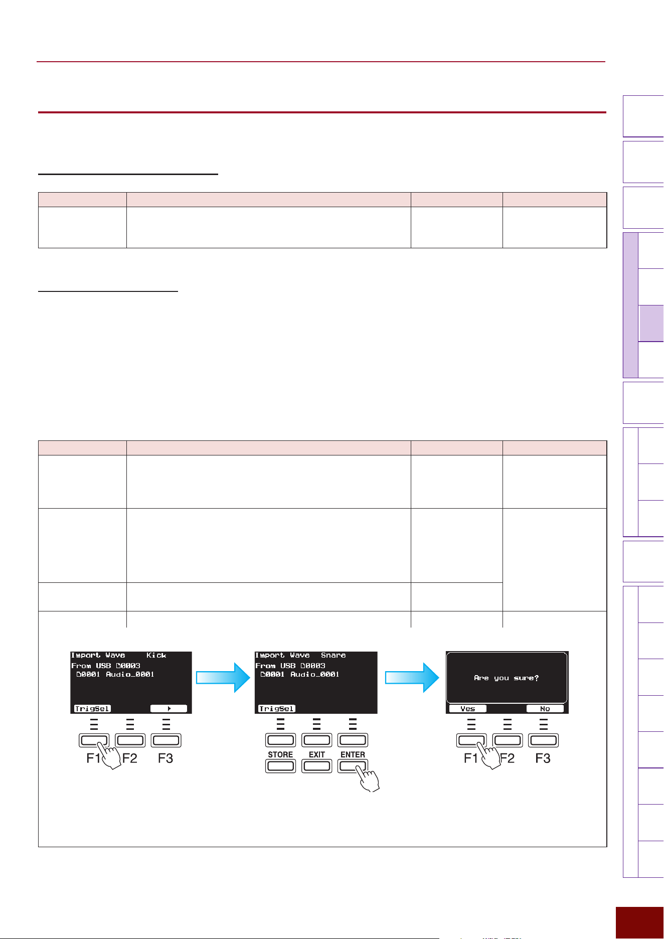
EAD50 EAD20 User Guide
126
Settings in Screens (Parameters)
Modifier
Knobs
LED
Rotary
Faders
[ MIC / TRIG ]
[ SCENE ][ CLICK ][ RECORDER ]
[ MENU ]
MicTriggerKitEffectRecorderLooperSamplingUtilityOutputAux In
USB AudioBluetooth
FileFactory
Reset
Version
[
LIVE SET
]
[F3] Setting
"
Kit
Used to specify a variety of settings related to electronic drum kits associated with the currently selected Scene.
[F3] Setting "Kit "Kit Volume
Parameter Explanation Setting Default Value
Volume
Used to set the overall volume of the currently selected electronic
drum kit. Consequently, it is balanced with the mic volume level
([MIC/TRIG]
"
[F3] Setting
"
Mic
"
Mic Volume).
0 – 127 Setting value in Scene
(Kit)
[F3] Setting "Kit "Inst
Used to set various settings for Insts assigned to each pad (each Trigger Input) for the currently selected Scene. Select the
pad and then configure respective settings.
NOTE
For more information about Trigger Inputs, refer to Pages 23 to 27.
[F3] Setting "Kit "Inst "Inst
Used to specify basic settings, such as selecting the Insts for assigning to respective Trigger Inputs (respective pads).
Page 1/4
Parameter Explanation Setting Default Value
On/Off Sets whether to produce a Trigger sound (On) or not (Off)
for each Trigger Input (each pad). When [TRIG] is On in the
lower left area of the panel, the setting can be changed using
buttons 1 to 5 in the bottom center area of the panel.
Off, On Always set to “On” for
Preset Scenes (Kit).
Category Selects the category for Insts assigned to respective Trigger
Inputs (respective pads).
NOTE
Selecting the Inst category automatically optimizes the Tuning,
Size, Muffling, Sustain, and Decay settings.
Refer to the Data List Setting value in Scene
(Kit)
Number Selects the numbers for Insts assigned to respective Trigger
Inputs (respective pads).
Refer to the Data List
Import Wave Imports audio files used as Insts from external memory.
Refer to the Data List
Use [+]/[−] buttons or the knob to select the audio
file located in external memory. Then on the screen
displayed by pressing the [F1] TrigSel button,
select the Trigger Input to assign to that audio file.
Press [F1] to import the file.
NOTE
The “F” in “F1 – F3” refers to “Function” and is used to name the buttons for explanatory
convenience. The names are not printed on the panel.
EAD50 EAD20 User Guide
127
Settings in Screens (Parameters)
Modifier
Knobs
LED
Rotary
Faders
[ MIC / TRIG ]
[ SCENE ][ CLICK ][ RECORDER ]
[ MENU ]
MicTriggerKitEffectRecorderLooperSamplingUtilityOutputAux In
USB AudioBluetooth
FileFactory
Reset
Version
[
LIVE SET
]
Page 2/4
Parameter Explanation Setting Default Value
Volume Sets the volume for Insts assigned to respective Trigger Inputs
(respective pads). Adjusted to balance the volume between
different Insts within the same kit.
0 – 127 Setting value in Scene
(Kit)
Pan Sets the position (pan) of Insts assigned to respective Trigger
Inputs (respective pads).
L63 – C – R63
Phase For each Inst assigned to each Trigger Input (each Pad),
this sets whether to invert the phase (On) or not (Off) when it
sounds.
Off, On
Delay Sets the delay for Insts assigned to respective Trigger Inputs
(respective pads).
0 ms – 0.1 ms – 10.0
ms
Page 3/4 (The parameters displayed will change depending on the Inst category.)
Parameter Explanation Setting Default Value
Tuning
Sets the pitch in 25-cent units for Insts assigned to respective
Trigger Inputs (respective pads). 0.01 corresponds to 1 cent.
NOTE
Cents are units of pitch equivalent to one hundredth of a semitone
(half-tone). (100 cents = 1 semitone)
−12.00 – 0.00 –
+12.00
Setting value in Scene
(Kit)
Size This sets the cymbal size effect for Insts assigned to
respective Trigger Inputs (respective pads).
−32 – 0 – +32
Attack
Sets the time required for Inst volume to reach the maximum
level after a pad is hit, for Insts assigned to respective Trigger
Inputs (respective pads).
−64 – 0 – +63
Muffling Sets the muffling level (head muting level) for Insts assigned
to respective Trigger Inputs (respective pads).
0 – +16
Sustain Sets the cymbal sustain effect for Insts assigned to respective
Trigger Inputs (respective pads).
–32 – 0
Decay Sets the time required for maximum volume to attenuate for
Insts assigned to respective Trigger Inputs (respective pads).
–16 – 0
Page 4/4
Parameter Explanation Setting Default Value
Gate Turns the gate function On/Off for each Trigger Input.
The “gate” function shuts off sound when it drops below a
specified volume value. Normally, the gate is left “open” when
Off and “closed” when On. It is used to prevent overlapping of
live drum mics or to filter the lingering sound of tom or snare
drums in order to adjust sound duration.
Off, On Setting value in Scene
(Kit)
Gate Threshold For each Trigger Input, this sets the threshold volume level for
cutting off input sounds (closing the gate). The gate will begin
closing when the sound drops below this setting value.
−73dB – −30dB
Gate Hold Once a gate is opened, this specifies the minimum time the
gate is held open before it begins closing. Even if the volume
drops below the threshold level the gate will remain closed
until the specified time has elapsed, after which it will begin
closing.
0 ms – 500 ms
Gate Attack This setting specifies how long after the gate starts opening
(the volume starts gradually increasing) until the normal
volume level is restored.
0.02 ms – 40 ms
Gate Release This setting specifies how long after the gate starts closing
(volume starts decreasing) until the volume is fully muted.
10 ms – 680 ms
EAD50 EAD20 User Guide
128
Settings in Screens (Parameters)
Modifier
Knobs
LED
Rotary
Faders
[ MIC / TRIG ]
[ SCENE ][ CLICK ][ RECORDER ]
[ MENU ]
MicTriggerKitEffectRecorderLooperSamplingUtilityOutputAux In
USB AudioBluetooth
FileFactory
Reset
Version
[
LIVE SET
]
[F3] Setting "Kit "Inst "Inst EQ
This product offers 4 EQ (equalizer) bands and high-pass filters that can be applied to Trigger sounds. This screen is used to
specify EQ-related settings individually for each Trigger Input. First, press the [F1] TrigSel button to select the Trigger Input,
and then specify settings for respective parameters. After selecting the type and color settings on the first page, more detailed
linked settings are set accordingly on the second and subsequent pages. After selecting the type and setting the color, more
detailed adjustments can be made using detailed settings on the second and subsequent pages.
NOTE
• The Trigger Inputs to which the settings are applied are displayed in the upper right area of the screen.
• For more information about equalizers, refer to the diagrams on Page 32.
Page 1/6
Parameter Explanation Setting Default Value
On/Off Sets whether to apply EQ (On) or not (Off).
Off, On Always set to “On” for
Preset Scenes (Kit).
Type Select the EQ type.
Refer to EQ Types. Setting value in Scene
(Kit)
Color Sets the EQ levels applied.
−64 – 0 – +63
Page 2/6
Parameter Explanation Setting Default Value
Low Freq This sets the midpoint of the EQ low frequency band.
32Hz – 2.0kHz Setting value in Scene
(Kit)
Low Gain Sets the gain level for the EQ low frequency band.
−12dB – 0dB –
+12dB
Low Q This sets the Q factor (frequency characteristics) for the EQ
low frequency band.
If Low Shape is set to LowShelving, then the Low Q value will
have no effect.
0.1 – 12.0
Low Shape This selects the shape of frequency characteristics for the EQ
low frequency band.
LowShelving,
PeakDip
Page 3/6
Parameter Explanation Setting Default Value
MidLow Freq
This sets the midpoint of the EQ low-to-mid frequency band.
100Hz – 10.0kHz Setting value in Scene
(Kit)
MidLow Gain Sets the gain level for the EQ low-to-mid frequency band.
−12dB – 0dB –
+12dB
MidLow Q This sets the Q factor (frequency characteristics) for the EQ
low-to-mid frequency band.
0.1 – 12.0
Page 4/6
Parameter Explanation Setting Default Value
MidHigh Freq
This sets the midpoint of the EQ mid-to-high frequency band.
100Hz – 10.0kHz Setting value in Scene
(Kit)
MidHigh Gain Sets the gain level for the EQ mid-to-
high
frequency band.
−12dB – 0dB –
+12dB
MidHigh Q This sets the Q factor (frequency characteristics) for the EQ
mid-to-high frequency band.
0.1 – 12.0
EAD50 EAD20 User Guide
129
Settings in Screens (Parameters)
Modifier
Knobs
LED
Rotary
Faders
[ MIC / TRIG ]
[ SCENE ][ CLICK ][ RECORDER ]
[ MENU ]
MicTriggerKitEffectRecorderLooperSamplingUtilityOutputAux In
USB AudioBluetooth
FileFactory
Reset
Version
[
LIVE SET
]
Page 5/6
Parameter Explanation Setting Default Value
High Freq
This sets the midpoint of the EQ high frequency band.
500Hz – 16.0kHz Setting value in Scene
(Kit)
High Gain Sets the gain level for the EQ
high
frequency band.
−12dB – 0dB –
+12dB
High Q This sets the Q factor (frequency characteristics) for the EQ
high frequency band.
If High Shape is set to HighShelving, then the High Q value
has no effect.
0.1 – 12.0
High Shape This selects the shape of frequency characteristics for the EQ
high frequency band.
If LPF is selected, the entire equalizer changes to functioning
as a low-pass filter.
HighShelving,
PeakDip, LPF
Page 6/6
Parameter Explanation Setting Default Value
HPF Freq Specifies whether to filter or not filter (Thru) Inst sounds
through a high-pass filter (HPF) (56Hz – 2.0kHz). Setting
the 22Hz – 2.0kHz filter will cut frequencies lower than the
applicable frequency.
Thru, 56Hz –
2.0kHz
Setting value in Scene
(Kit)
HPF Q This sets the Q factor (frequency characteristics) for the high-
pass filter.
0.1 – 12.0
[F3] Setting "Kit "Inst "InstTranComp
Applies Transient Effects (attack or release effects) and Compressor Effects to Insts assigned to respective Trigger Inputs
(respective pads). Switches both effects On/Off at the same time. On this screen, first press the [F1] TrigSel button to select
the Trigger Input and then specify respective parameter settings. After selecting the type and specifying the depth setting
on the first page, more detailed parameter settings are configured automatically on the second and subsequent pages. After
selecting the type and setting the depth, more detailed adjustments can be made using detailed setting parameters on the
second and subsequent pages.
Page 1/3
Parameter Explanation Setting Default Value
On/Off Simultaneously applies Transient Effects (attack or release
effects) and Compressor Effects.
Off, On Always set to “On” for
Preset Scenes (Kit).
Type Selects the Effect type for each Inst.
Refer to the Transient
Compressor Type List
Setting value in Scene
(Kit)
Depth For each Inst, this sets the Effect level applied.
0 – 127
Page 2/3
Parameter Explanation Setting Default Value
Tran Attack
For each Inst, this adjusts the transient attack effect level.
−50 – 0 – +50 Setting value in Scene
(Kit)
Tran Release
For each Inst, this adjusts the transient release effect level.
−50 – 0 – +50
Tran Sensitivity For each Inst, this sets the sensitivity with which transient
effects are applied based on the hitting force.
1 – 6
EAD50 EAD20 User Guide
130
Settings in Screens (Parameters)
Modifier
Knobs
LED
Rotary
Faders
[ MIC / TRIG ]
[ SCENE ][ CLICK ][ RECORDER ]
[ MENU ]
MicTriggerKitEffectRecorderLooperSamplingUtilityOutputAux In
USB AudioBluetooth
FileFactory
Reset
Version
[
LIVE SET
]
Page 3/3
Parameter Explanation Setting Default Value
Comp Threshold
For each Inst, this sets the level (threshold level) where
Compressor Effects begin being applied.
−48dB – 6dB Setting value in Scene
(Kit)
Comp Ratio For each Inst, this sets the compression ratio applied to
volume levels above the Comp Threshold value.
1.0, 1.5, 2.0, 3.0, 4.0,
5.0, 7.0, 10.0, 20.0
Comp Attack For each Inst, this sets how long it takes, immediately after
hitting, to reach maximum Compressor Effects.
1 ms – 40 ms
Comp Release For each Inst, this sets how long it takes for Compressor
Effects to decrease from the maximum point to zero.
10 ms – 680 ms
Comp Out Level For each Inst, this specifies the Compressor output level.
−18.0dB – 0.0dB –
+18.0dB
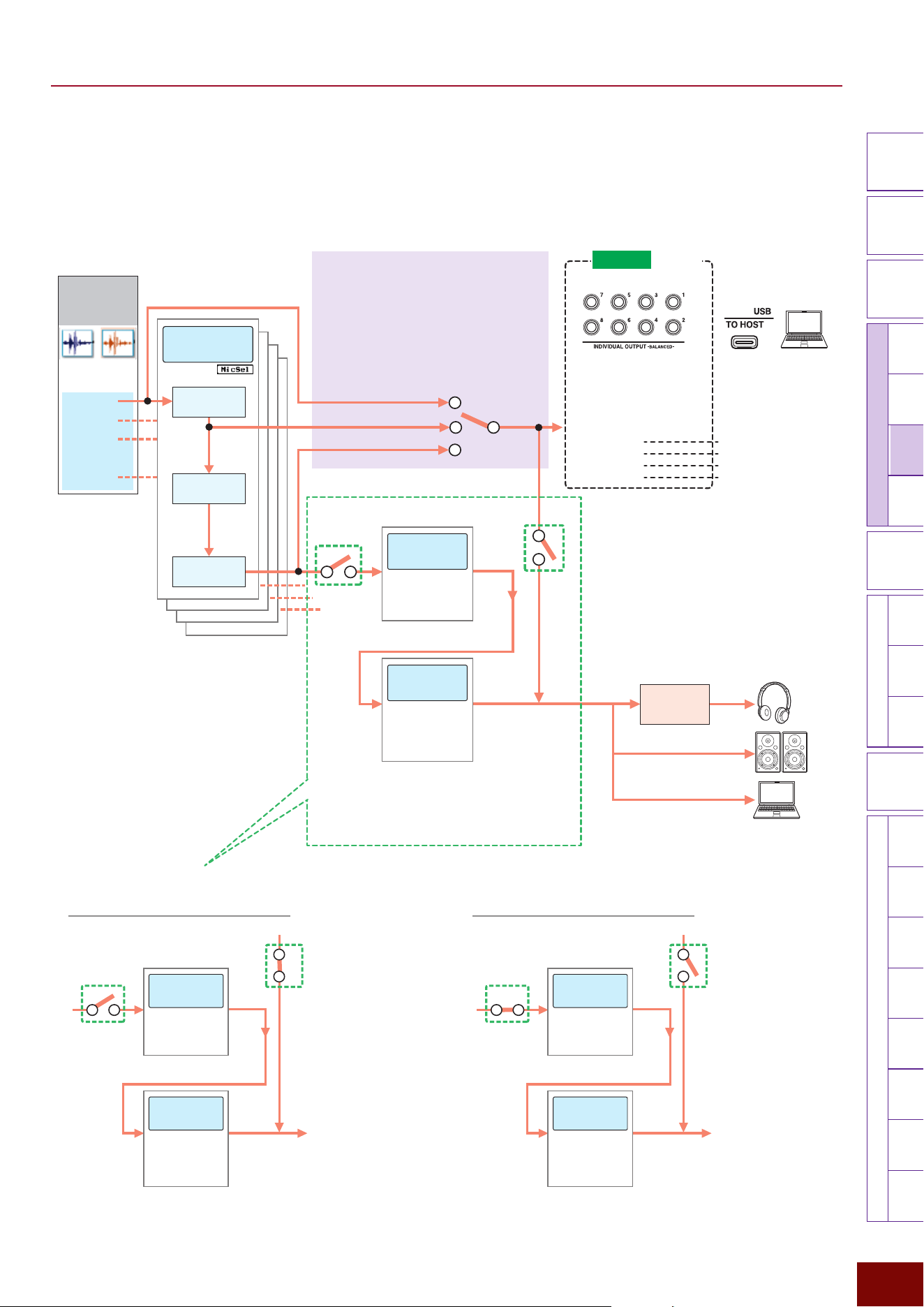
EAD50 EAD20 User Guide
131
Settings in Screens (Parameters)
Modifier
Knobs
LED
Rotary
Faders
[ MIC / TRIG ]
[ SCENE ][ CLICK ][ RECORDER ]
[ MENU ]
MicTriggerKitEffectRecorderLooperSamplingUtilityOutputAux In
USB AudioBluetooth
FileFactory
Reset
Version
[
LIVE SET
]
A
B
Setting Branching Points
Any of the following three branching
points can be used to extract sound that
has not had System Effects or Master
Effects applied and adjust it individually
with separate devices, regardless of Effect
Thru** settings.
Effects Process Flow Diagram (Page 28): Detailed Diagram
of Trigger Input Channels
Trigger Input
Channel
(Electronic Drums)
Kick
:
:
Snare
TrigXX
*
Trig3
Trigger-Specific
Effects
Parts EQ
Transient
Compressor
Insertion Effect1
If EQ Tran Thru =
• If EQ Thru
• If Tran Thru
• If Off
System
Effects
Master
Effects
• Reverb
• FX1
• FX2
• Master FX
• Master
Compressor
• Master EQ
Phones
EQ
[OUTPUT] jacks
(Main Out)
[MENU]
"
Output
"
Phones EQ
[USB TO HOST] terminal
[MIC/TRIG]
"
[F3] Setting
"
Kit
"
Inst
"
Inst Out
"
IndivOut
[INDIVIDUAL OUTPUT] jacks
• IndivOut 1/2
• IndivOut 3/4
• IndivOut 5/6
• IndivOut 7/8
All USB audio channels
will conform to IndvOut
settings.
[USB TO HOST] terminal
• USB Audio Out 3/4
• USB Audio Out 5/6
• USB Audio Out 7/8
• USB Audio Out 9/10
[MIC/TRIG]
"
[F3] Setting
"
Effect
[MIC/TRIG]
"
[F3] Setting
"
Effect
EAD50
Only
* Trig22 for EAD50 and
Trig9 for EAD20
NOTE
USB Audio Out 1/2 = Main Out L/R
Whether or not to output mic and
Trigger sounds, with System Effects and
Master Effects applied, to respective
output destinations can be specified
**
NOTE
It is also possible to extract only the return sound from
System Effects. For more information, refer to Page 28.
[F3] Setting "Kit "Inst "Inst Out
This sets the route for sending performance sounds from each electronic drum Inst to external outputs.
Switching routes using Effect Thru settings for each Trigger Input
Route for Trigger Input sound with Effect Thru*** = Off
(with System Effects/Master Effects applied)
A
B
A: On
B: Off
System
Effects
Master
Effects
"
Reverb
• FX1
• FX2
• Master FX
• Master
Compressor
• Master EQ
[MIC/TRIG]
"
[F3] Setting
"
Effect
[MIC/TRIG]
"
[F3] Setting
"
Effect
Whether or not to output
sound to respective output
destinations (Phones, Main
Out, or USB Audio Out 1/2)
cannot be specified for each
Trigger Input
Route for Trigger Input sound with Effect Thru*** = On
(without System Effects or Master Effects applied)
A
B
A: Off
B: On
System
Effects
Master
Effects
• Reverb
• FX1
• FX2
• Master FX
• Master
Compressor
• Master EQ
[MIC/TRIG]
"
[F3] Setting
"
Effect
[MIC/TRIG]
"
[F3] Setting
"
Effect
Whether or not to output
sound to respective output
destinations (Phones, Main
Out, or USB Audio Out 1/2)
can be specified for each
Trigger Input
****
** [MIC/TRIG]
"
[F3] Setting
"
Effect
"
Effect Out
"
Main Out
"
Phones Out, USB Audio Out 1/2
***
[MIC/TRIG]
"
[F3] Setting
"
Kit
"
Inst
"
Inst Out
"
Effect Thru
****
[MIC/TRIG]
"
[F3] Setting
"
Kit
"
Inst
"
Inst Out
"
Phones Out, Main Out, USB Audio Out 1/2
Effects Applied to All Trigger Inputs
Waveform
Real
Ambi
EAD50 EAD20 User Guide
132
Settings in Screens (Parameters)
Modifier
Knobs
LED
Rotary
Faders
[ MIC / TRIG ]
[ SCENE ][ CLICK ][ RECORDER ]
[ MENU ]
MicTriggerKitEffectRecorderLooperSamplingUtilityOutputAux In
USB AudioBluetooth
FileFactory
Reset
Version
[
LIVE SET
]
Page 1/2
Parameter Explanation Setting Default Value
EQ Tran Thru Performance sounds from each electronic drum Inst (each
Trigger Input) can be extracted at an intermediate branching
point in the Effects process flow diagram in order to output
the sound via a separate jack without applying subsequent
effects. This setting sets the branch point where the sound is
extracted.
• Off: Branches before applying System Effects.
• EQ Thru: Branches before starting part EQ.
• Tran Thru: Branches before applying Transient Compressor.
Off, EQ Thru,
Tran Thru
Always set to “Off” for
Preset Scenes (Kit).
Effect Thru This specifies whether to send performance sounds from
each electronic drum Inst (each Trigger Input) through the
System Effects and Master Effects sections (Off) or not (On).
If On is selected, sound from the branching point selected
by EQ Tran Thru is routed to a point after the Master Effects
section.
Off, On
Main Out This is only displayed if the Effect Through setting is On. This
individually sets whether sound from the branching point
selected in EQ Tran Thru is output from an [OUTPUT] jack (On)
or not (Off).
Off, On Always set to “On” for
Preset Scenes (Kit).
Phones Out This is only displayed if the Effect Through setting is On. This
individually sets whether sound from the branching point
selected in EQ Tran Thru is output from an [PHONES] jack (On)
or not (Off).
Off, On
USB Audio Out
1/2
This is only displayed if the Effect Through setting is On. This
individually sets whether sound from the branching point
selected in EQ Tran Thru is output from an [USB TO HOST]
terminal (On) or not (Off).
Off, On
EAD50 EAD20 User Guide
133
Settings in Screens (Parameters)
Modifier
Knobs
LED
Rotary
Faders
[ MIC / TRIG ]
[ SCENE ][ CLICK ][ RECORDER ]
[ MENU ]
MicTriggerKitEffectRecorderLooperSamplingUtilityOutputAux In
USB AudioBluetooth
FileFactory
Reset
Version
[
LIVE SET
]
Page 2/2 (
EAD50
)
Parameter Explanation Setting Default Value
IndivOut
(
EAD50
only)
Performance sounds from each electronic drum Inst (each
Trigger Input) can be diverted at a branching point in the
effects process flow diagram and output separately for each
jack or channel.
This sets the INDIVIDUAL jack location for outputting
performance sounds from each electronic drum Inst.
NOTE
Because IndivOut1–8 are linked to USB Audio Out3–10, these
settings also automatically determined the output location for USB
Audio Out3–10. For example, if Mic1 = L1 + R2 is specified, then
Mic1 sound is output to a computer or other device via USB Audio
3/4 ports.
Off, L1+R2, L3+R4,
L5+R6, L7+R8,
L1, R2, L3, R4, L5,
R6, L7, R8, (L+R)1,
(L+R)2, (L+R)3,
(L+R)4, (L+R)5,
(L+R)6, (L+R)7,
(L+R)8
* For a description of
respective setting
values, refer to the
table on page bottom
of Page 116.
Always set to “Off” for
Preset Scenes (Kit).
IndivOut Vol
(
EAD50
only)
This adjusts the volume of each electronic drum Inst (each
Trigger Input) output as performance sounds via a branching
point in the Effects process flow diagram (Page 131). If
Variable is specified, the volume is linked to [MIC/TRIG] slider
operations.
Variable, 1 – 127 Always set to “Variable”
for Preset Scenes (Kit).
Page 2/2 (
EAD20
)
Parameter Explanation Setting Default Value
USB AudOut
(
EAD20
only)
Each electronic drum Inst (each Trigger Input) in performance
sounds can be extracted at a branching point in the Effects
process flow diagram (Page 131) and output separately via
one of the USB audio channels 3 to 8. This setting sets which
USB channel to use.
Off, L3+R4, L5+R6,
L7+R8, L9+R10, L3,
R4, L5, R6, L7, R8,
L9, R10, (L+R)3,
(L+R)4, (L+R)5,
(L+R)6, (L+R)7,
(L+R)8, (L+R)9,
(L+R)10
* For a description of
respective setting
values, refer to the
table on page bottom
of Page 117.
Always set to “Off” for
Preset Scenes (Mic).
USB AudOut Vol
(
EAD20
only)
This adjusts the volume of each electronic drum Inst (each
Trigger Input) in performance sounds output via a branching
point in the Effects process flow diagram (Page 131). If
“Variable” is specified, the volume is linked to [MASTER]
slider operations.
Variable, 1 – 127 Always set to “Variable”
for Preset Scenes (Mic).
EAD50 EAD20 User Guide
134
Settings in Screens (Parameters)
Modifier
Knobs
LED
Rotary
Faders
[ MIC / TRIG ]
[ SCENE ][ CLICK ][ RECORDER ]
[ MENU ]
MicTriggerKitEffectRecorderLooperSamplingUtilityOutputAux In
USB AudioBluetooth
FileFactory
Reset
Version
[
LIVE SET
]
[F3] Setting "Kit "Voice
For this product, 4 layers are available for each Trigger Input Source (each zone). By assigning a Voice to respective layers,
multiple Voices can be overlaid to create a heavier sound. This sets the Voice assigned to respective layers or settings for
other related parameters.
[F3] Setting "Kit "Voice "Voice
This specifies settings that directly affect performances, such as the assignment of Voices to respective layers or how Voices
for respective layers are layered.
Page 1/6
Parameter Explanation Setting Default Value
Category This selects the category for Voices assigned to respective
layers.
Refer to the Voice List Setting value in Scene
(Kit)
Number This selects the Voice number for Voices assigned to
respective layers.
Refer to the Voice List
Page 2/6
Parameter Explanation Setting Default Value
Volume Sets the volume of the Voices assigned to respective layers.
0 – 127 Setting value in Scene
(Kit)
Pan This sets the position (pan) of Voices assigned to respective
layers.
L63 – C – R63
Page 3/6
Parameter Explanation Setting Default Value
Tuning This is used to tune Voices assigned to respective layers.
−24.0 – 0.0 – +24.0 Setting value in Scene
(Kit)
Attack Sets the attack speed (speed from when a pad is hit until it
reaches its maximum expression level) for Voices assigned to
respective layers. The larger the value, the faster the sound
increases.
−64 – 0 – +63
Decay Sets the decay speed (speed for the maximum expression
level to decay to no sound) for Voices assigned to respective
layers. The larger the setting value, the faster the sound
decreases.
–64 – 0
Cutoff Sets the cutoff frequency for filters applied to Voices assigned
to respective layers.
−64 – 0 – +63
Resonance Sets the Q factor (filter resonance) for filters applied to Voices
assigned to respective layers. Increases the signal near the
Filter Cutoff Frequency adding character to the sound.
−64 – 0 – +63
EAD50 EAD20 User Guide
135
Settings in Screens (Parameters)
Modifier
Knobs
LED
Rotary
Faders
[ MIC / TRIG ]
[ SCENE ][ CLICK ][ RECORDER ]
[ MENU ]
MicTriggerKitEffectRecorderLooperSamplingUtilityOutputAux In
USB AudioBluetooth
FileFactory
Reset
Version
[
LIVE SET
]
Page 4/6
Parameter Explanation Setting Default Value
Mono/Poly For each layer, this specifies how sound is produced in
response to successive pad hits.
When the same pad is hit successively, the “Mono” setting
causes sounds produced from later hits to mute the sounds
produced earlier. The Poly setting sustains previously
produced sounds to the end instead of muting them.
Mono, Poly Setting value in Scene
(Kit)
Choke Send
For each layer, this specifies whether to send mute instructions
for the choke technique (1 – 64) or not (Off).
If set within the 1 – 64 range, then when a sound is expressed,
the Voice (layer) with the same number as specified for the
Choke Receive function is muted.
Off, 1 – 64
Choke Receive For each layer, this specifies whether to receive mute
instructions for the choke technique (1 – 64) or not (Off). If set
within the 1 – 64 range, then the Voice (layer) with the same
number as specified for the Choke Send function is muted.
Off, 1 – 64
Humanize For each layer, this specifies whether to create a natural
variation in sounds from successively hitting the same pad (to
avoid an excessively uniform sound) (On) or not (Off).
Off, On
Fixed Velocity For each layer, this specifies whether to set a fixed volume
level for expressing each Voice (1 – 127) or to vary the volume
based on how hard the pad is hit (Off).
Off, 1 – 127
Page 5/6
Parameter Explanation Setting Default Value
Hold Mode For each Voice, this sets how sound is played back when
pads are hit.
On:
Striking the pad plays the sounds repeatedly in a loop, and
striking the pad again stops the sound. MIDI Key On and Key
Off messages are output alternately each time the pad is hit.
Off:
With this setting, the pad plays one-shot sounds. A MIDI Note
On message is sent when a pad is hit, and the corresponding
Note Off message is sent automatically after the gate time has
elapsed.
Off, On Setting value in Scene
(Kit)
Layer Mode
This sets how Voices registered for each layer are expressed.
Stack:
This plays all Voices registered to layers simultaneously when
the pad is hit.
Alt:
This plays all Voices registered to layers in sequential order
each time the pad is hit.
Stack, Alt
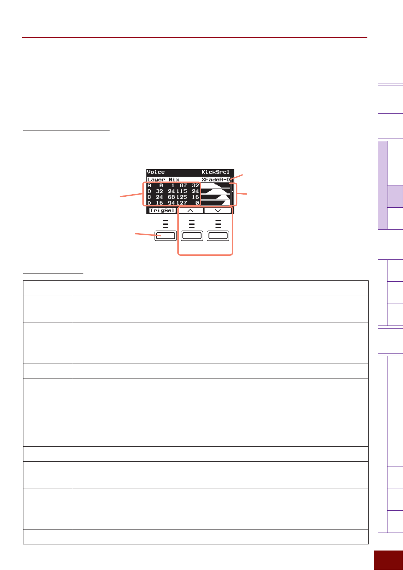
EAD50 EAD20 User Guide
136
Settings in Screens (Parameters)
Modifier
Knobs
LED
Rotary
Faders
[ MIC / TRIG ]
[ SCENE ][ CLICK ][ RECORDER ]
[ MENU ]
MicTriggerKitEffectRecorderLooperSamplingUtilityOutputAux In
USB AudioBluetooth
FileFactory
Reset
Version
[
LIVE SET
]
Page 6/6
Layer Mix
This screen sets how strongly respective Layers A to D respond to the force (velocity) used to hit each electronic drum pad.
The setting is set while viewing a graph of the actual sound level produced, indicated on the vertical axis, in response to the
force used to hit pads (indicated on the horizontal axis). This setting can be used to specify different layers that generate
different levels of sound depending on how hard pads are hit or used to adjust the mixing, such as the volume balance between
respective layers.
Basic Operating Procedure
1. Select the Trigger Input Source as described on Page 65 and then press the [EXIT] button to display this screen again.
2. Select the layer type in the top row on the screen (Layer Mix).
3. To make finer corrections, move the cursor to the numeric settings area at the bottom of the screen and specify the setting
for each layer.
F1 F2 F3
Press to select the Trigger
Used to move the cursor
In respective graphs for Layers A, B, C, and D, the
white area indicates where sound is generated.
• Horizontal axis: Pad hitting force (velocity)
• Vertical axis: Sound level actually generated
Numeric settings area
(For more details, see
the next page.)
Layer type (refer to the table below)
List of Layer Types
Normal This sets the normal response level for all layers, where the force used to hit pads is reflected directly in determining the volume of the
Voice generated.
AddB This setting assumes a Voice is only assigned to Layers A and B.
• For Layer A, it sets a normal response for the entire velocity range.
• For Layer B, it sets a volume of 0 for the velocity range from 0 to a user-specified velocity value and sets a normal response for
velocities from that user-specified velocity up to 127.
FadeInB This setting assumes a Voice is only assigned to Layers A and B.
• For Layer A, it sets a normal response for the entire velocity range.
• For Layer B, it sets a volume of 0 for the velocity range from 0 to a user-specified velocity value and sets a fade-in response for
velocities from that user-specified velocity up to 127.
SwA,B This setting assumes a Voice is only assigned to Layers A and B.
It sets a normal response for Layers A and B, but switches the layer expressed at a user-specified velocity threshold value.
XFadeA,B This setting assumes a Voice is only assigned to Layers A and B.
It sets a cross-fade transition between the layers expressed at the user-
specified velocity threshold value.
AddB,C This setting assumes a Voice is assigned to Layers A, B, and C.
• For Layer A, it sets a normal response for the entire velocity range.
• For Layers B and C, it sets a volume of 0 for the velocity range from 0 to a user-specified velocity value and sets a normal response for
velocities from that user-specified velocity up to 127.
FadeInB,C This setting assumes a Voice is assigned to Layers A, B, and C.
• For Layer A, it sets a normal response for the entire velocity range.
• For Layers B and C, it sets a volume of 0 for the velocity range from 0 to a user-specified velocity value and sets a fade-in response for
velocities from that user-specified velocity up to 127.
SwA-C This setting assumes a Voice is assigned to Layers A, B, and C.
It sets a normal response for Layers A, B, and C, but switches the layer expressed at user-specified velocity threshold values.
XFadeA-C This setting assumes a Voice is assigned to Layers A, B, and C. It sets a cross-fade transition between the layers expressed at user-
specified velocity threshold values.
AddB-D This setting assumes a Voice is assigned to all Layers.
• For Layer A, it sets a normal response for the entire velocity range.
• For Layers B, C, and D, it sets a volume of 0 for the velocity range from 0 to a user-specified velocity value and sets a normal response
for velocities from that user-specified velocity up to 127.
FadeInB-D This setting assumes a Voice is assigned to all Layers.
• For Layer A, it sets a normal response for the entire velocity range.
• For Layers B, C, and D, it sets a volume of 0 for the velocity range from 0 to a user-specified velocity value and sets a fade-in response
for velocities from that user-specified velocity up to 127.
SwA-D This setting assumes a Voice is assigned to all Layers.
It sets a normal response for all layers, but switches the layer expressed at user-specified velocity threshold values.
XFadeA-D This setting assumes a Voice is assigned to all Layers. It sets a cross-fade transition between the layers expressed at user-specified velocity
threshold values.
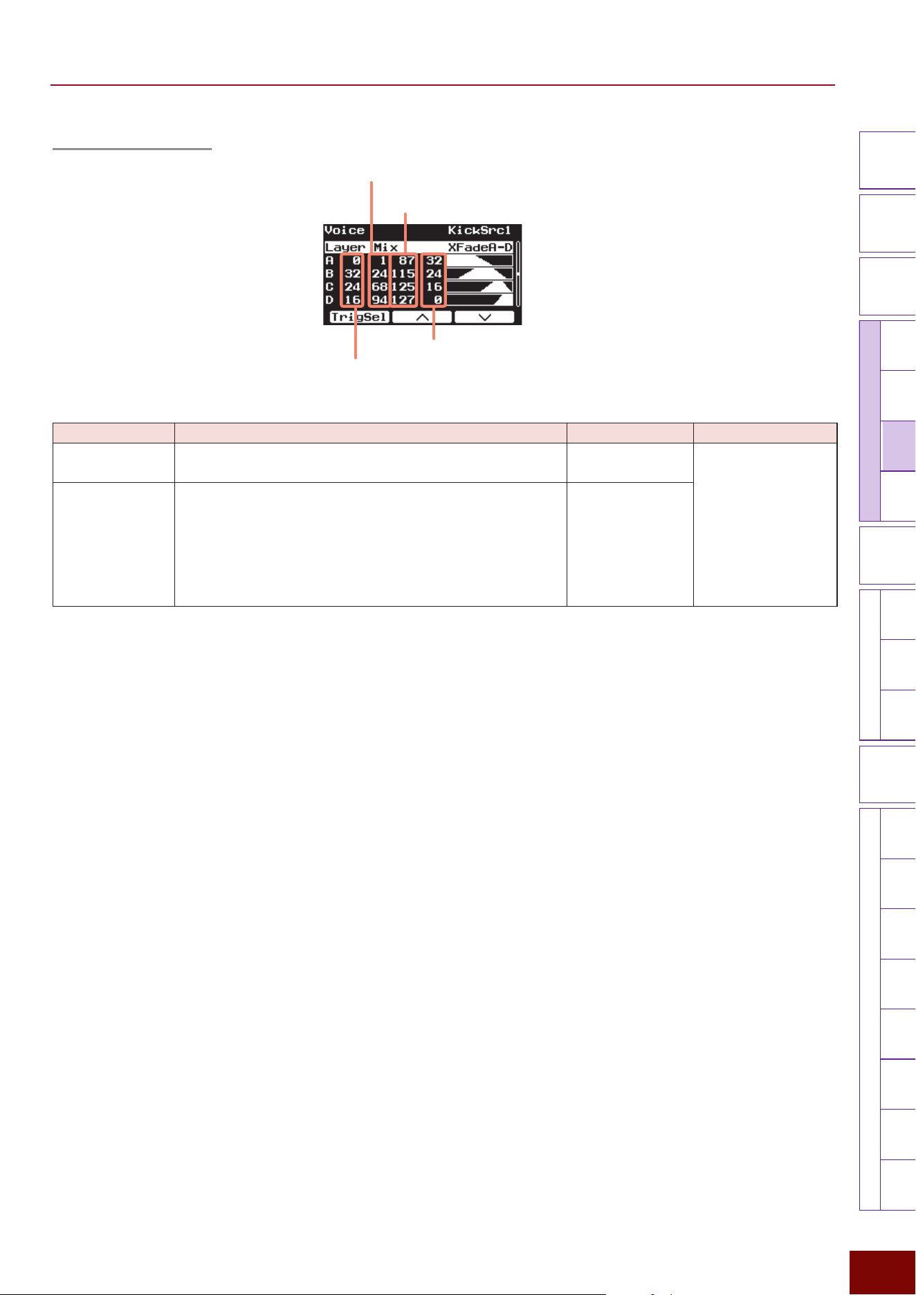
EAD50 EAD20 User Guide
137
Settings in Screens (Parameters)
Modifier
Knobs
LED
Rotary
Faders
[ MIC / TRIG ]
[ SCENE ][ CLICK ][ RECORDER ]
[ MENU ]
MicTriggerKitEffectRecorderLooperSamplingUtilityOutputAux In
USB AudioBluetooth
FileFactory
Reset
Version
[
LIVE SET
]
Numeric settings area
Velocity Fade Low
Velocity Fade High
Velocity Limit Low
Velocity Limit High
Parameter Explanation Setting Default Value
Velocity Limit Low
Velocity Limit High
This sets the response force (velocity) range for pad hits in the
currently selected layer.
1 – 127 Setting value in Scene
(Kit)
Velocity Fade Low
Velocity Fade High
This sets the degree to which the volume level gradually fades
in/out in response to the force of each hit at either end of the
velocity limit. The higher the value, the greater the degree of
fade-in/fade-out. At the left end of the graph, where VelLimitLo
= 0, the volume level gradually fades in response to the force
of each hit. At the right end of the graph, where VelLimitHi = 0,
the volume level fades out in response to the force of each hit.
0 – 127
EAD50 EAD20 User Guide
138
Settings in Screens (Parameters)
Modifier
Knobs
LED
Rotary
Faders
[ MIC / TRIG ]
[ SCENE ][ CLICK ][ RECORDER ]
[ MENU ]
MicTriggerKitEffectRecorderLooperSamplingUtilityOutputAux In
USB AudioBluetooth
FileFactory
Reset
Version
[
LIVE SET
]
[F3] Setting "Kit "Voice "Voice MIDI
This specifies pad settings related to MIDI messages for respective layers A to D.
Press the [F1] TrigSel button to select the Trigger Input Source and layer before specifying corresponding settings.
Page 1/4
Parameter Explanation Setting Default Value
Note Num 1–4
Sets the MIDI notes and channels output when the applicable
pad is hit. Up to four MIDI notes can be assigned to each
layer for output. In addition, when the MIDI note and channel
are received for Note 1 of Layer A, it assumes the Trigger
signal was emitted from the corresponding Trigger Input
Source.
NOTE
If Global is specified, then the channel is set by [MENU]
"
Utility
"
MIDI Global Channel.
Off, 0 – 127 For Preset Scenes (Kit),
refer to “MIDI Note Map.”
Note Ch 1 – 4
Global, 1 – 16 Always set to “Global” for
Preset Scenes (Kit)
Page 2/4
Parameter Explanation Setting Default Value
Note Port This sets the MIDI port for Note Ch 1 – 4. If the port is set to “2,”
notes are not output from the [MIDI OUT] terminal.
NOTE
If Global is specified, then the port number is set by [MENU]
"
Utility MIDI Global Port.
Global, 1 – 2 Always set to “Global” for
Preset Scenes (Kit)
Note Gate Time This sets the time it takes for MIDI output when the pad is hit
to switch the setting from Note On to Note Off.
0.0 s – 9.9 s Always set to “0.3 s” for
Preset Scenes (Kit).
EAD50 EAD20 User Guide
139
Settings in Screens (Parameters)
Modifier
Knobs
LED
Rotary
Faders
[ MIC / TRIG ]
[ SCENE ][ CLICK ][ RECORDER ]
[ MENU ]
MicTriggerKitEffectRecorderLooperSamplingUtilityOutputAux In
USB AudioBluetooth
FileFactory
Reset
Version
[
LIVE SET
]
Page 3/4
Parameter Explanation Setting Default Value
CC Number Note This product can send a control change message to an
external device when a pad is hit. If control change numbers
are specified for applicable pads, this setting outputs
control change values based on how hard (velocity) the
corresponding pad is hit.
Off, 0 – 127 Always set to “Off” for
Preset Scenes (Kit).
CC Number
Position
This product can send a control change message to
an external device when a pad is hit. If control change
numbers are specified here for applicable pads, then control
change values are output based on the position where the
corresponding pad is hit. MIDI sending functions in the
following cases.
• The Trigger Input Source is Foot (
EAD50
: Foot1
–
2) or HH
(
EAD50
: HH1
–
2) (the beginning of the Trigger Input Source
and layer A are used)
• A pad type that supports the position detection function is
currently connected/selected ([MIC/TRIG]
"
[F3] Setting
"
Trigger
"
Trig In
"
Pad
"
Position = “On”).
Furthermore, if the control change message for the number
specified here is received, it will either result in operating the
foot controller based on that value or detect the Voice position
and play the corresponding Voice. MIDI receiving functions in
the following cases.
• The Trigger Input Source is (
EAD50
: Foot1
–
2) or HH (
EAD50
:
HH1
–
2).
• A Voice that supports the position detection function is
selected.
NOTE
For HH1 and HH2, the OpBw setting affects all Trigger Input Sources.
Off, 0 – 127 They are always set
as indicated below for
Preset Scenes (Kit).
EAD50
:
Foot1Src Layer A: 4
HH1OpBw Layer A: 4
Other: Off
EAD20
:
FootSrc Layer A: 4
HHOpBw Layer A: 4
Other: Off
CC Channel For each layer, this sets the MIDI channel for outputting
control change messages.
NOTE
If Global is specified, then the channel is set by [MENU]
"
Utility
"
MIDI Global Channel.
Global, 1 – 16 Always set to “Global” for
Preset Scenes (Kit)
CC Port For each layer, this sets the MIDI port for outputting control
change messages. If the port is set to “2,” notes are not
output from the [MIDI OUT] terminal.
NOTE
If Global is specified, then the port number is set by [MENU]
"
Utility
MIDI Global Port.
Global, 1 – 2
Page 4/4
Parameter Explanation Setting Default Value
CC Min Value For each layer, this sets the minimum control change value
applied when the pad is hit lightly. It is only enabled for MIDI
sending.
0 – 127 Always set to “0” for
Preset Scenes (Kit).
CC Max Value For each layer, this sets the maximum control change value
applied when a pad is hit hard. It is only enabled for MIDI
sending.
0 – 127 Always set to “127” for
Preset Scenes (Kit).
EAD50 EAD20 User Guide
140
Settings in Screens (Parameters)
Modifier
Knobs
LED
Rotary
Faders
[ MIC / TRIG ]
[ SCENE ][ CLICK ][ RECORDER ]
[ MENU ]
MicTriggerKitEffectRecorderLooperSamplingUtilityOutputAux In
USB AudioBluetooth
FileFactory
Reset
Version
[
LIVE SET
]
[F3] Setting "Kit "Voice "Voice Func
In addition to playing Voices when a pad is hit, this setting can assign other functions to each Trigger Input Source, such as
changing kit numbers or tempo values. Press the [F1] TrigSel button to select the Trigger Input Source before selecting the
function to assign.
Selectable
Functions
Explanation Setting Default Value
Supplemental
Parameter
Off No function is assigned.
ー ー
Scene Select Assigns a function that selects the specified Scene.
Scene Number Specifies the Scene number.
EAD50
: P001 – P071
EAD20
: P001 – P051
U001 – U200
Setting value in Scene
(Function)
Scene Inc Assigns a function that selects the next Scene.
ー ー
Scene Dec Assigns a function that selects the number immediately before
the Scene.
ー ー
Scene Toggle Assigns a function that alternately switches between two
Scenes, either Scene A or B.
ー ー
Scene Number
A
Specifies the Scene number as A.
EAD50
: P001 – P071
EAD20
: P001 – P051
U001 – U200
Setting value in Scene
(Function)
Scene Number
B
Specifies the Scene number as B.
EAD50
: P001 – P071
EAD20
: P001 – P051
U001 – U200
Tempo Inc Assigns a function that increases the tempo value.
ー ー
Value Sets a tempo value to be added.
1 – 127
Setting value in Scene
(Function)
Tempo Dec Assigns a function that decreases the tempo value.
ー ー
Value Sets a tempo value to be subtracted.
1 – 127
Setting value in Scene
(Function)
Tempo Tap Assigns a function that assigns a tempo setting based on the
time interval between pad hits.
ー ー
Tempo Control Assigns a function for changing the tempo.
ー ー
Control Type Velocity:
Sets the tempo between the minimum (Min Value) and
maximum (Max Value) values, based on hit force level.
Volume:
Sets the tempo between the minimum (Min Value) and
maximum (Max Value) values, based on how far the FC7
foot controller is pressed.
Toggle:
Each hit toggles the value between minimum (Min Value)
and maximum (Max Value) values.
Hold A:
Sets the tempo to the maximum value (Max Value) as long
as the foot switch is pressed or when the pad is hit hard. It
sets the tempo to the minimum value (Min Value) whenever
the foot switch is not pressed or if the pad is hit lightly.
Hold B:
Opposite of Hold A.
Velocity, Volume,
Toggle, Hold A,
Hold B
Setting value in Scene
(Function)
Min Value Sets the minimum tempo value for this function.
30.0 – 300.0
Max Value Sets the maximum tempo value for this function.
30.0 – 300.0
EAD50 EAD20 User Guide
141
Settings in Screens (Parameters)
Modifier
Knobs
LED
Rotary
Faders
[ MIC / TRIG ]
[ SCENE ][ CLICK ][ RECORDER ]
[ MENU ]
MicTriggerKitEffectRecorderLooperSamplingUtilityOutputAux In
USB AudioBluetooth
FileFactory
Reset
Version
[
LIVE SET
]
Selectable
Functions
Explanation Setting Default Value
Supplemental
Parameter
Modifier Control
This assigns functionality for freely controlling the effects
corresponding to the operations of the Modifier knobs on the
left side of the panel.
ー ー
Control Type Velocity:
Sets the effect level between the minimum (Min Value) and
maximum (Max Value) values, based on how hard the pad
is hit.
Volume:
Sets the effect level between the minimum (Min Value) and
maximum (Max Value) values, based on how far the FC7
foot controller is pressed.
Toggle:
Each hit toggles the value between minimum (Min Value)
and maximum (Max Value) values.
Hold A:
Sets the maximum value (Max Value) as long as the foot
switch is pressed or when the pad is hit hard. It sets it to the
minimum value (Min Value) whenever the foot switch is not
pressed or if the pad is hit lightly.
Hold B:
Opposite of Hold A.
Velocity, Volume,
Toggle, Hold A,
Hold B
Setting value in Scene
(Function)
Min Value Sets the minimum value for effects by this function.
0 – 127
Max Value Sets the maximum value for effects by this function.
0 – 127
Modifier1 – 6
Enables (with check mark) or disables (without check mark)
this function for each knob.
For each parameter:
• With check mark
• Without check mark
Mic/Trig Control
Assigns a function that switches each effect On/Off and each
channel (mic input and Trigger sounds) On/Off.
ー ー
Control Type Specifies method for switching control On/Off.
Toggle:
Toggles each parameter On/Off, each time the pad is hit.
Hold A:
The setting is held On as long as the foot switch is pressed
and switched Off when not pressed. Switched On when the
pad is hit with a velocity of 64 or higher and Off when hit
with a velocity less than 64.
Hold B:
Opposite of Hold A.
Toggle, Hold A,
Hold B
Setting value in Scene
(Function)
Reverb –
Master EQ
For each effect block, this specifies whether or not to switch
the effect On (with check mark) or Off (without check mark).
For each parameter:
• With check mark
• Without check mark
Setting value in Scene
(Function)
EAD50
:
Mic1 – Mic5
EAD20
:
Mic L/R
For each mic jack, this specifies whether or not to switch the
effect On (with check mark) or Off (without check mark).
For each parameter:
• With check mark
• Without check mark
EAD50
:
Kick – Trig22
EAD20
:
Kick – Foot
For each Trigger Input Source, this specifies whether or not to
switch the effect On (with check mark) or Off (without check
mark).
For each parameter:
• With check mark
• Without check mark
Always set to “Without
check mark” for Preset
Scenes (Function).
EAD50 EAD20 User Guide
142
Settings in Screens (Parameters)
Modifier
Knobs
LED
Rotary
Faders
[ MIC / TRIG ]
[ SCENE ][ CLICK ][ RECORDER ]
[ MENU ]
MicTriggerKitEffectRecorderLooperSamplingUtilityOutputAux In
USB AudioBluetooth
FileFactory
Reset
Version
[
LIVE SET
]
Selectable
Functions
Explanation Setting Default Value
Supplemental
Parameter
Talk Control For mic input settings, this assigns a function for switching to
the talk mode or returning to the previous mode.
CAUTION
If the talk function is On, a variety of mic settings are changed
to values for talking. In particular, the talk function will
increase gain, so drum playing with talk set to On could cause
unexpectedly high volumes. Be extra careful to avoid playing
music with the talk setting On.
ー ー
Control Type Toggle:
Toggles the talk mode On/Off each time the pad is hit.
Hold A:
Holds the talk mode On as long as the foot switch is
pressed and restores the previous mode (for playing music)
whenever not pressed. Hitting the pad with a velocity of 64
or higher switches the control type to the talk mode and
hitting it with a velocity less than 64 switches it back to the
previous state (for playing music).
Hold B:
Opposite of Hold A.
Toggle, Hold A,
Hold B
Setting value in Scene
(Function)
Mic Input
(
EAD50
only)
Selects which mic jack to switch to the talk mode.
Mic1 – 5
Setting value in Scene
(Function)
Xstick Control Assigns a function for switching the electronic drum pad
Xstick mode On/Off ([MIC/TRIG]
"
Trigger
"
Trig In
"
Pad
"
Xstick On/Off).
ー ー
Control Type Toggle:
Toggles the electronic drum Xstick function On/Off each
time the pad is hit.
Hold A:
Holds the Xstick function On as long as the foot switch is
pressed and turns it Off whenever it is not pressed. Hitting
the pad with a velocity of 64 or higher turns this On and
hitting it with a velocity less than 64 turns this Off.
Hold B:
Opposite of Hold A.
Toggle, Hold A,
Hold B
Always set to “Toggle”
for Preset Scenes
(Function).
EAD50
:
Kick, Snare,
Trig3 – 5
EAD20
:
Kick, Snare,
Trig3, Trig4
For each Trigger Input Source, this specifies whether or not to
switch the Xstick effect On (with check mark) or Off (without
check mark).
For each parameter:
• With check mark
• Without check mark
Setting value in Scene
(Function)
EAD50 EAD20 User Guide
143
Settings in Screens (Parameters)
Modifier
Knobs
LED
Rotary
Faders
[ MIC / TRIG ]
[ SCENE ][ CLICK ][ RECORDER ]
[ MENU ]
MicTriggerKitEffectRecorderLooperSamplingUtilityOutputAux In
USB AudioBluetooth
FileFactory
Reset
Version
[
LIVE SET
]
Selectable
Functions
Explanation Setting Default Value
Supplemental
Parameter
Sound Off This assigns a function that stops all electronic drum sounds
(Voices) currently being played.
ー ー
Click Start/Stop Assigns a function for starting/stopping Click playback.
ー ー
Recorder Control A Assigns the following functions.
• Function for starting/stopping recording by the Recorder
• Function for starting Looper recording or starting playback
• Function for starting/stopping recording by Sampling
ー ー
Recorder Control B Assigns the following functions.
• Function for starting/stopping audio file playback by the
Recorder.
• Function for stopping Looper playback or clearing Looper
data
• Function for starting/stopping Sampling playback
ー ー
Live Set Select
(
EAD50
only)
Assigns a function that selects the specified Live Set.
ー ー
Live Set
Number
Specifies a Live Set number.
U01 – U50
Setting value in Scene
(Function)
Live Set Inc
(
EAD50
only)
Assigns a function that selects the next Live Set number.
ー ー
Live Set Dec
(
EAD50
only)
Assigns a function that selects the previous Live Set number.
ー ー
Live Set Step
Select
(
EAD50
only)
Assigns a function that selects the specified Live Set step.
ー ー
Live Set Step
Number
Specifies a Live Set
Step
number.
S01 – S50
Setting value in Scene
(Function)
Live Set Step Inc
(
EAD50
only)
Assigns a function that selects the next step number for the
current Live Set.
ー ー
Live Set Step Dec
(
EAD50
only)
Assigns a function that selects the previous step number for
the current Live Set.
ー ー
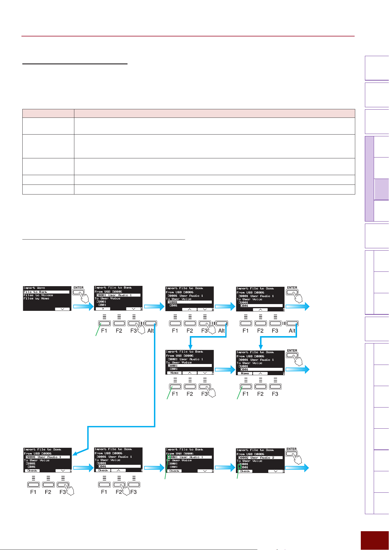
EAD50 EAD20 User Guide
144
Settings in Screens (Parameters)
Modifier
Knobs
LED
Rotary
Faders
[ MIC / TRIG ]
[ SCENE ][ CLICK ][ RECORDER ]
[ MENU ]
MicTriggerKitEffectRecorderLooperSamplingUtilityOutputAux In
USB AudioBluetooth
FileFactory
Reset
Version
[
LIVE SET
]
[F3] Setting "Kit "User Voice
In addition to Voices included internally for Trigger sounds (electronic sounds produced based on Trigger signals), User Voices
can also be used by loading an external audio file.
NOTE
For more information about the memory configuration for user-defined Voices, see from Pages 33 to 34.
Parameter Explanation
Import Wave This is used to load audio files and assign them to a User Voice.
For more information, refer to the following.
Edit Velocity Limit
L/H
This sets how waveforms are sounded for each User Voice.
Each User Voice is composed of 10 wave banks, with waveforms from the corresponding bank sounded
within the specified velocity range. For operating instructions, refer to the following.
Sort Wave This is used to freely change the order of waves within the User Voice. For operating instructions, refer to
“Basic Operations” on Page 67.
Delete Wave This deletes waves imported to this product.
WaveMem Info This displays the usage status of wave memory to which wave is imported.
■ Import Wave (Importing External Audio Files into this product)
File to Bank (Importing User Voices into a Bank)
z
Importing 1 File into 1 Bank
The following describes importing one audio file into one bank.
1.
Select an audio file in
external memory.
2.
Select a User Voice and bank
as the import destination.
3.
Press [ENTER] to import
the file.
Press [Alt] 2 times
Press [Alt] 2 times
Plays selected audio
file.
[Alt] button
Allows naming the User Voice
at the import destination.
Allows naming the User Voice
bank at the import destination.
Check mark indicates import
destination
Check mark indicates User
Audio 1 will be imported
When “Completed”
is displayed,
importing is
finished.
When “Completed”
is displayed,
importing is
finished.
When “Completed”
is displayed,
importing is
finished.
Repeat
steps
1 to 3.
1.
Select file to import.
2.
Select the User Voice
and bank at the import
destination.
4.
Repeat steps 1 to 3. Then press
[ENTER] to import the file.
3.
Press the [F1] Check button to
mark the file with a check mark.
z
Importing Multiple Files to Multiple Banks
at the Same Time
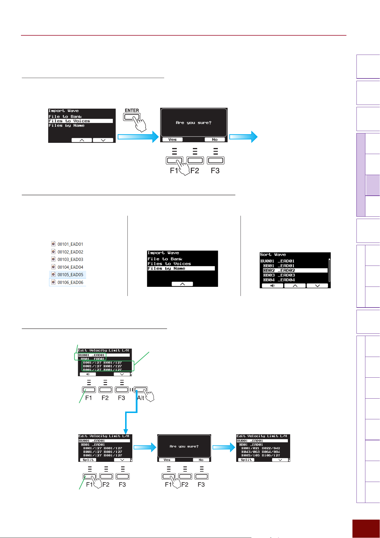
EAD50 EAD20 User Guide
145
Settings in Screens (Parameters)
Modifier
Knobs
LED
Rotary
Faders
[ MIC / TRIG ]
[ SCENE ][ CLICK ][ RECORDER ]
[ MENU ]
MicTriggerKitEffectRecorderLooperSamplingUtilityOutputAux In
USB AudioBluetooth
FileFactory
Reset
Version
[
LIVE SET
]
■ Edit Velocity Limit L/H (Setting the Velocity Range for Each Bank)
Set the following individually for each bank.
Emits sound from the
currently selected bank.
Settings for having the assigned audio file emit
sound separately for each velocity range are
specified with a single press of the [F1] button.
Confirm the velocity range for
each bank.
Move the cursor here to specify the
velocity range (Min/Max Values).
Select the User Voice number and
bank number.
NOTICE
For this setting, be sure to press the [ENTER] button to save the setting before
turning the power off. Note that the setting will be lost if the power is turned off
without saving.
■ Import Wave (Importing External Audio Files into this product)
Files to Voices (Importing Files into Voices)
This successively imports, in a sorted state, all audio files in the root directory of external memory into empty User Voices, one
at a time, in ascending order of Voice number.
When “Completed” is
displayed, importing is
finished.
Files by Name (Successively Importing Files in File Name Order)
By preparing audio file names in advance, audio files can be imported as desired with a single press of a button.
1.
Prepare the audio file names, such as by using a
computer. For example, to import User Voice 001 to
banks 01 to 06, name files as follows.
2.
Connect the external memory device, which contains
the files prepared in step 1, to this product.
3.
Display the following screen.
[MIC/TRIG]
"
[F3] Setting
"
Kit
"
User Voice
"
Import Wave
"
Files by Name
4.
When the [ENTER] button is pressed and the “Now
importing…” button is displayed, importing is finished.
5.
Check the import status on the following screen.
[MIC/TRIG]
"
[F3] Setting
"
Kit
"
User Voice
"
Sort Wave
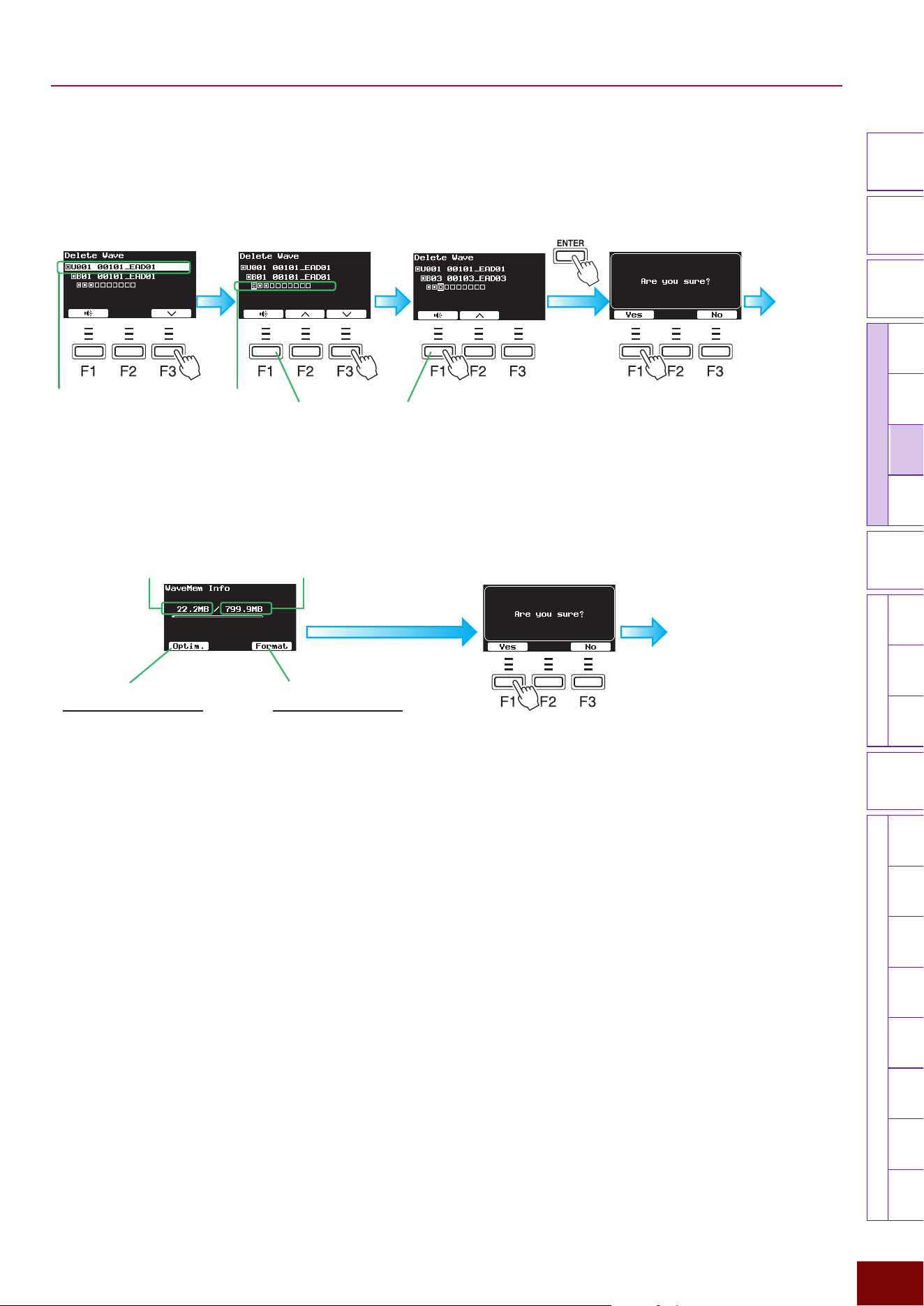
EAD50 EAD20 User Guide
146
Settings in Screens (Parameters)
Modifier
Knobs
LED
Rotary
Faders
[ MIC / TRIG ]
[ SCENE ][ CLICK ][ RECORDER ]
[ MENU ]
MicTriggerKitEffectRecorderLooperSamplingUtilityOutputAux In
USB AudioBluetooth
FileFactory
Reset
Version
[
LIVE SET
]
■ Delete Wave
Deletes entire banks of waves imported to this product.
1.
Select the User Voice using the
[+]/[−] buttons or knob.
2.
Use the [F3] button to move the
cursor to the bank row.
3.
Use the [F2] and [F3] buttons to
move the cursor to the bank to
be deleted.
4.
Press the [F1] Yes button to
delete the bank.
The wave file assigned to the bank
corresponding to the cursor position can
be heard.
The process is
finished when
“Completed” is
displayed.
Bank rowUser Voices
■ WaveMem Info (Wave Memory Usage Status)
The process is finished
when “Completed” is
displayed.
[F1] Optim.
(optimizes wave memory)
This optimizes the wave memory.
Optimization involves reorganizing the
memory area to expand the memory area
available for use. If memory becomes
fragmented, it might not be possible to
import audio files even if there is plenty of
memory space available. In such cases, this
function can be used to resolve the problem
by increasing the contiguous memory space
available.
Press the [F1] button to display a
confirmation screen. Then press [F1] Yes to
optimize the memory.
[F3] Format
(formats wave memory)
This formats the wave memory. Formatting
a USB flash drive will delete all wave data
saved in the device.
Press the [F3] button to display a
confirmation screen. Then press the [F1]
Yes button to optimize the memory.
Wave memory
used
Total wave
memory
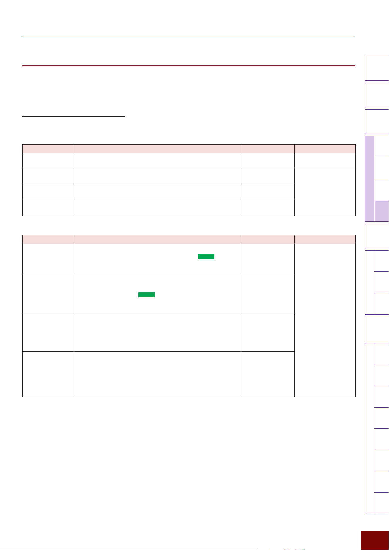
EAD50 EAD20 User Guide
147
Settings in Screens (Parameters)
Modifier
Knobs
LED
Rotary
Faders
[ MIC / TRIG ]
[ SCENE ][ CLICK ][ RECORDER ]
[ MENU ]
MicTriggerKitEffectRecorderLooperSamplingUtilityOutputAux In
USB AudioBluetooth
FileFactory
Reset
Version
[
LIVE SET
]
[F3] Setting
"
Effect
This specifies settings for effects applied to Voices (tone generator parts) based on the sounds input via mic jacks and signals
input from Trigger jacks. For more information about the product’s Effects process flow diagram, refer to pages 28, 115,
and 131.
[F3] Setting "Effect "Reverb
This sets Reverb settings, one of three System Effects (Page 30) included in this product.
Page 1/4
Parameter Explanation Setting Default Value
On/Off Sets whether to apply Reverb Effects (On) or not (Off).
Off, On Always set to “On” for
Preset Scenes (Effect).
Category Selects the Reverb type category.
Refer to the Effect
Type List.
Setting value in Scene
(Effect)
Type Selects the Reverb type.
Refer to the Effect
Type List.
Send All
This specifies the Reverb level to send (send level) for all
sound parts produced by this product.
0 – 127
Page 2/4
Parameter Explanation Setting Default Value
Send Mic This sets the amount of Reverb to send (send level) to Reverb
Effects for sounds input via mic jacks. For the
EAD50
model,
the mic jack is selected on the screen displayed by pressing
[F1] MicSel before specifying the setting.
0 – 127
Setting value in Scene
(Effect)
Send Mic Curve This selects the curve for determining the level of Reverb
Effects to send based on the volume level of input sounds
from mic jacks. For the
EAD50
model, the mic jack is selected
on the screen displayed by pressing [F1] MicSel before
specifying the setting.
C1 – C7
Send Trig For each Trigger Input, this sets the level sent to Reverb
effects for Voices (tone generator parts) sounded based on
input signals from Trigger jacks. The Trigger Input is selected
on the screen displayed by pressing the [F1] TrigSel before
specifying the setting.
0 – 127
Send Trig Curve
For each Trigger Input, this selects the curve for determining
whether to send Reverb Effects at send levels corresponding
to input signal levels of Voices sounded based on input signals
from Trigger jacks. The Trigger Input is selected on the screen
displayed by pressing the [F1] TrigSel before specifying the
setting.
C1 – C7
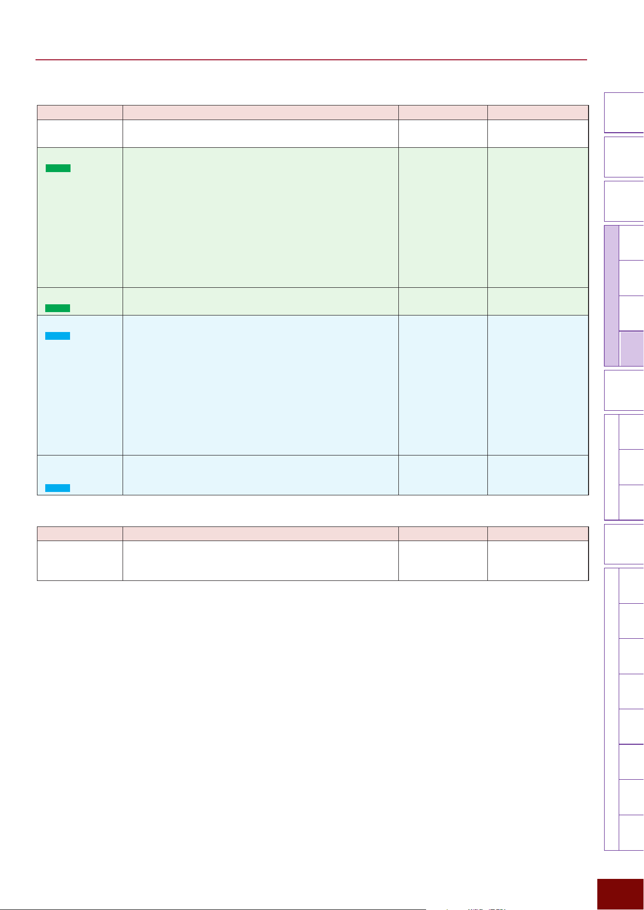
EAD50 EAD20 User Guide
148
Settings in Screens (Parameters)
Modifier
Knobs
LED
Rotary
Faders
[ MIC / TRIG ]
[ SCENE ][ CLICK ][ RECORDER ]
[ MENU ]
MicTriggerKitEffectRecorderLooperSamplingUtilityOutputAux In
USB AudioBluetooth
FileFactory
Reset
Version
[
LIVE SET
]
Page 3/4
Parameter Explanation Setting Default Value
Return This specifies the same return level for sound signals
processed with Reverb Effects for all parts.
0 – 127
Setting value in Scene
(Effect)
IndivOut
(
EAD50
only)
This can be used to individually output wet sounds generated
with Reverb Effects. For this setting, the output destination is
specified.
Off, L1+R2, L3+R4,
L5+R6, L7+R8,
L1, R2, L3, R4, L5,
R6, L7, R8, (L+R)1,
(L+R)2, (L+R)3,
(L+R)4, (L+R)5,
(L+R)6, (L+R)7,
(L+R)8
* For a description of
respective setting
values, refer to the
table on page bottom
of Page 116.
Always set to “Off” for
Preset Scenes (Effect).
Return IndivOut
(
EAD50
only)
This sets the sound signal level that is output to output
destinations specified above.
0 – 127 Always set to “0” for
Preset Scenes (Effect).
USB AudOut
(
EAD20
only)
This can be used to individually output only wet sounds
generated with Reverb Effects via USB audio channels. This
setting sets the channel for outputting the sounds.
Off, L3+R4, L5+R6,
L7+R8, L9+R10, L3,
R4, L5, R6, L7, R8,
L9, R10, (L+R)3,
(L+R)4, (L+R)5,
(L+R)6, (L+R)7,
(L+R)8, (L+R)9,
(L+R)10
* For a description of
respective setting
values, refer to the
table on page bottom
of Page 117.
Always set to “Off” for
Preset Scenes (Effect).
Return USB
AudOut
(
EAD20
only)
This sets the sound signal output level to the channels
specified above.
0 – 127 Always set to “0” for
Preset Scenes (Effect).
Page 4/4 and after
Parameter Explanation Setting Default Value
Parameter Group
(varies depending
on Effect type)
This adjusts the various parameters associated with the
current Reverb type.
Refer to the Effect
Type List.
Setting value in Scene
(Effect)
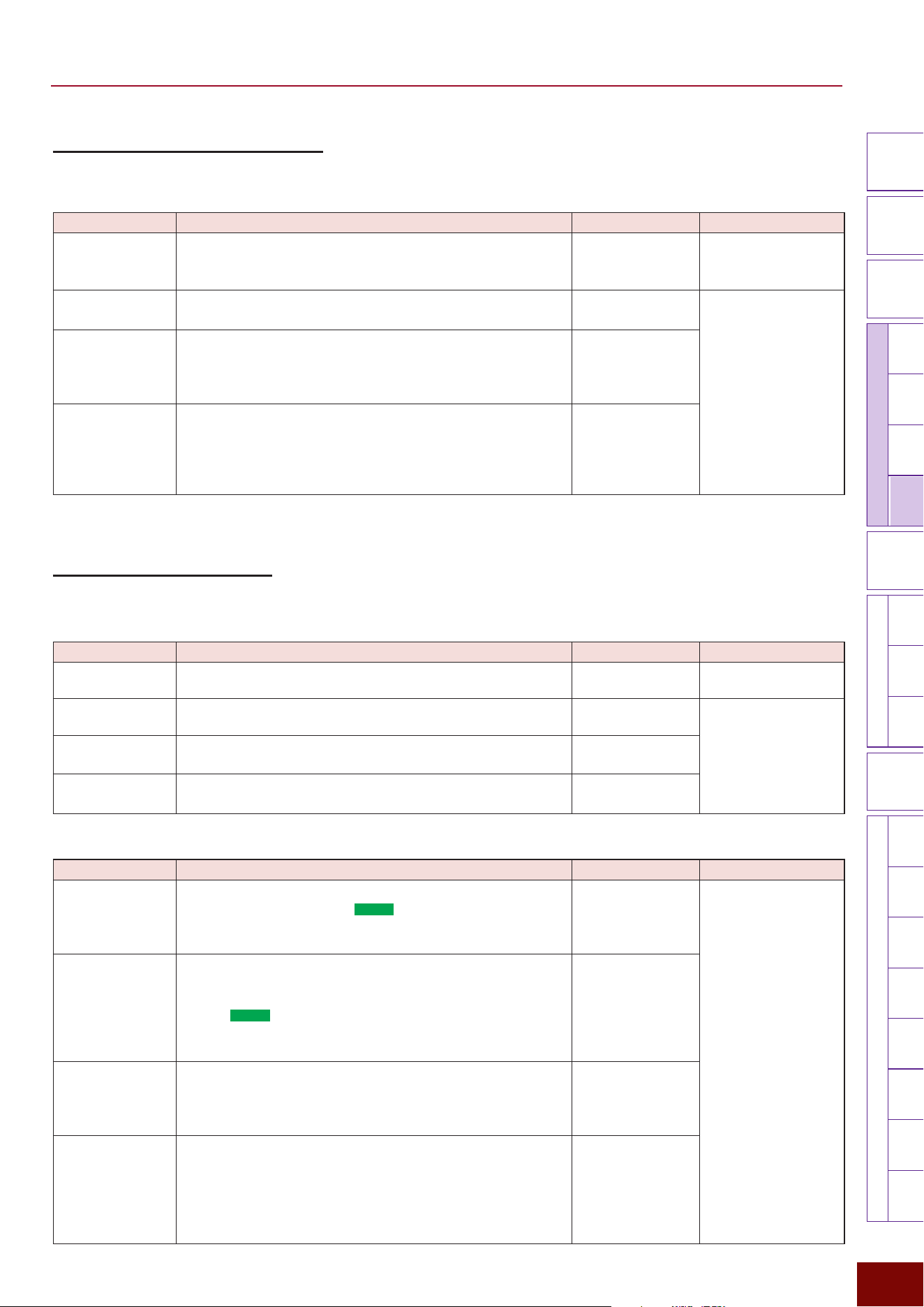
EAD50 EAD20 User Guide
149
Settings in Screens (Parameters)
Modifier
Knobs
LED
Rotary
Faders
[ MIC / TRIG ]
[ SCENE ][ CLICK ][ RECORDER ]
[ MENU ]
MicTriggerKitEffectRecorderLooperSamplingUtilityOutputAux In
USB AudioBluetooth
FileFactory
Reset
Version
[
LIVE SET
]
[F3] Setting "Effect "Real Ambi
This sets Real Ambi-related settings for each Trigger source. The setting is only enabled for Insts (Voices) assigned to Trigger
sources that support Real Ambience (Page 29).
Parameter Explanation Setting Default Value
On/Off For Insts of kits included in the currently selected Scene and
that support Real Ambience, this selects whether to use Real
Ambience waveforms (On) or not (Off).
Off, On Always set to “On” for
Preset Scenes (Effect).
Depth All This sets the Real Ambience depth level uniformly for all
Trigger Inputs.
0 – 127
Setting value in Scene
(Effect)
Depth Trig This sets the Real Ambience depth level for Voices sounded
based on input signals from each Trigger Input. The Trigger
Input is selected on the screen displayed by pressing the [F1]
TrigSel before specifying the setting.
0 – 127
Depth Trig Curve For each Trigger Input, this selects from 7 curve types for
determining whether to apply a Real Ambience depth level
corresponding to the input signal level. The Trigger Input is
selected on the screen displayed by pressing the [F1] TrigSel
before specifying the setting.
C1 – C7
[F3] Setting "Effect "FX1
This sets FX1 settings, one of three System Effects (Page 30) included in this product.
Page 1/4
Parameter Explanation Setting Default Value
On/Off Sets whether to apply FX1 effects (On) or not (Off).
Off, On Always set to “On” for
Preset Scenes (Effect).
Category Selects the FX1 type category.
Refer to the Effect
Type List.
Setting value in Scene
(Effect)
Type Selects the FX1 type.
Refer to the Effect
Type List.
Send All
This specifies the FX1 effect level to send (send level) for all
sound parts produced by the product.
0 – 127
Page 2/4
Parameter Explanation Setting Default Value
Send Mic This sets the FX1 Effect level to send (send level) for sounds
input via mic jacks. For the
EAD50
model, the mic jack is
selected on the screen displayed by pressing the [F1] MicSel
before specifying the setting.
0 – 127
Setting value in Scene
(Effect)
Send Mic Curve
This selects the curve for determining the level of FX1 effects
to send based on the volume level of input sounds from mic
jacks.
For the
EAD50
model, the mic jack is selected on the screen
displayed by pressing [F1] MicSel before specifying the
setting.
C1 – C7
Send Trig For each Trigger Input, this sets the level sent to FX1 effects
for Voices sounded based on input signals from Trigger jacks.
The Trigger Input is selected on the screen displayed by
pressing the [F1] TrigSel before specifying the setting.
0 – 127
Send Trig Curve For each Trigger Input, this selects the curve for determining
whether to send FX1 effects at send levels corresponding to
input signal levels of Voices sounded based on input signals
from Trigger jacks.
The Trigger Input is selected on the screen
displayed by pressing the [F1] TrigSel before specifying the
setting.
C1 – C7
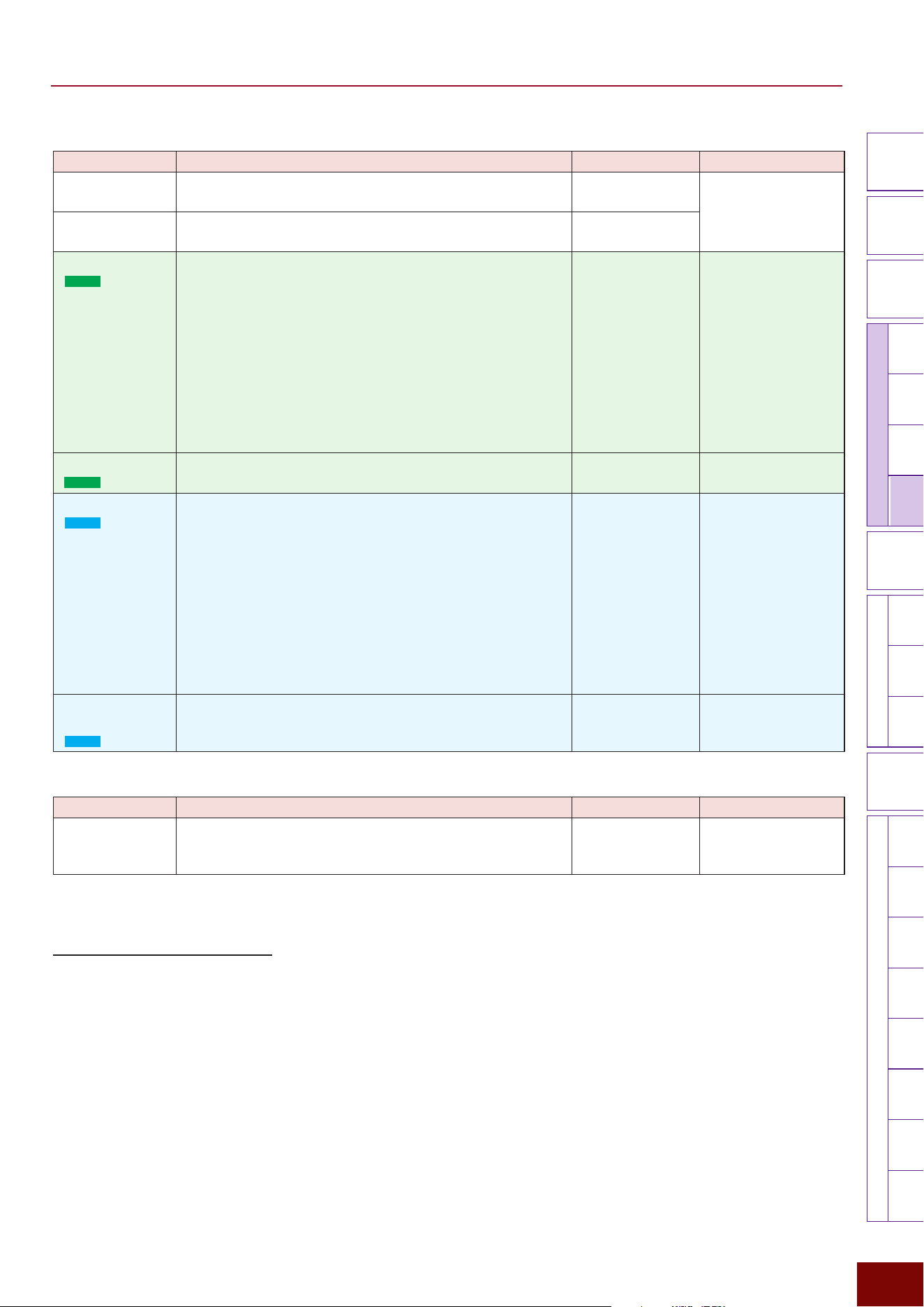
EAD50 EAD20 User Guide
150
Settings in Screens (Parameters)
Modifier
Knobs
LED
Rotary
Faders
[ MIC / TRIG ]
[ SCENE ][ CLICK ][ RECORDER ]
[ MENU ]
MicTriggerKitEffectRecorderLooperSamplingUtilityOutputAux In
USB AudioBluetooth
FileFactory
Reset
Version
[
LIVE SET
]
Page 3/4
Parameter Explanation Setting Default Value
Send to Reverb This specifies the same Reverb send level for all channels
with sound processed with FX1 effects.
0 – 127
Setting value in Scene
(Effect)
Return This specifies the same return level for all channels with
sound processed with FX1 effects.
0 – 127
IndivOut
(
EAD50
only)
This can be used to individually output wet sounds generated
with FX1 effects. For this setting, the output destination is
specified.
Off, L1+R2, L3+R4,
L5+R6, L7+R8,
L1, R2, L3, R4, L5,
R6, L7, R8, (L+R)1,
(L+R)2, (L+R)3,
(L+R)4, (L+R)5,
(L+R)6, (L+R)7,
(L+R)8
* For a description of
respective setting
values, refer to the
table on page bottom
of Page 116.
Always set to “Off” for
Preset Scenes (Effect).
Return IndivOut
(
EAD50
only)
This sets the sound signal level that is output to output
destinations specified above.
0 – 127 Always set to “0” for
Preset Scenes (Effect).
USB AudOut
(
EAD20
only)
This can be used to individually output only wet sounds
generated with FX1 via USB audio channels. This setting sets
the channel for outputting the sounds.
Off, L3+R4, L5+R6,
L7+R8, L9+R10, L3,
R4, L5, R6, L7, R8,
L9, R10, (L+R)3,
(L+R)4, (L+R)5,
(L+R)6, (L+R)7,
(L+R)8, (L+R)9,
(L+R)10
* For a description of
respective setting
values, refer to the
table on page bottom
of Page 117.
Always set to “Off” for
Preset Scenes (Effect).
Return USB
AudOut
(
EAD20
only)
This sets the sound signal output level to the channels
specified above.
0 – 127 Always set to “0” for
Preset Scenes (Effect).
Page 4/4
Parameter Explanation Setting Default Value
Parameter Group
(varies depending
on Effect type)
This adjusts various parameters associated with the current
FX1 type.
Refer to the Effect
Type List.
Setting value in Scene
(Effect)
[F3] Setting "Effect "FX2
This sets FX2 settings, one of three System Effects (Page 30) included in this product.
Setting parameters are the same as on the following screen.
[F3] Setting
"
Effect
"
FX1
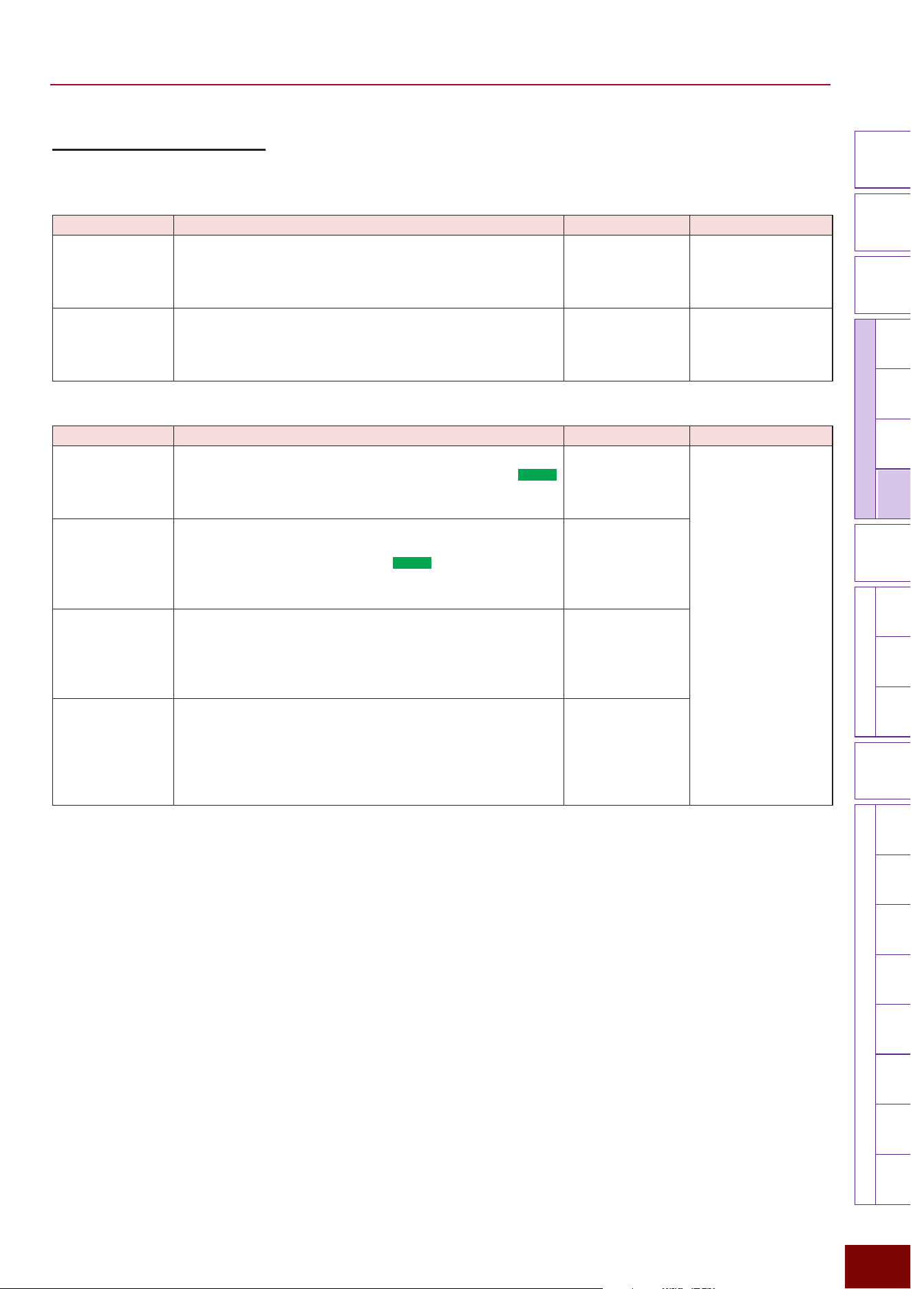
EAD50 EAD20 User Guide
151
Settings in Screens (Parameters)
Modifier
Knobs
LED
Rotary
Faders
[ MIC / TRIG ]
[ SCENE ][ CLICK ][ RECORDER ]
[ MENU ]
MicTriggerKitEffectRecorderLooperSamplingUtilityOutputAux In
USB AudioBluetooth
FileFactory
Reset
Version
[
LIVE SET
]
[F3] Setting "Effect "Dry
This specifies settings for sounds input from mic jacks or Trigger jacks that are not processed with System Effects (dry sounds).
Page 1/2
Parameter Explanation Setting Default Value
On/Off The “On” setting enables routes that do not apply System
Effects to sounds.
The “Off” setting prevents producing a dry sound. (Equivalent
to Level All = 0.)
Off, On Always set to “On” for
Preset Scenes (Effect).
Level All
For all input sound from the microphone jack and Trigger Input
jacks, this sets the amount that will not be sent to the System
Effects. The “0” setting prevents producing a dry sound.
(Equivalent to Dry = Off.)
0 – 127
Setting value in Scene
(Effect)
Page 2/2
Parameter Explanation Setting Default Value
Level Mic This sets the dry level (the amount of sound without System
Effects applied) for sounds input via mic jacks. For the
EAD50
model, the mic jack is selected in the screen displayed by
pressing [F1] MicSel before specifying the setting.
0 – 127
Setting value in Scene
(Effect)
Level Mic Curve
This selects a curve used to determine the dry level (the
amount without System Effects applied) for mic input sounds
based on the volume level.
For the
EAD50
model,
the mic jack
is selected on the screen displayed by pressing [F1] MicSel
before specifying the setting.
C1 – C7
Level Trig For the Voice sound that is produced from the input signal
from each Trigger Input jack, this sets the dry level (the
amount that does not process the System Effects) The Trigger
Input is selected on the screen displayed by pressing the [F1]
TrigSel before specifying the setting.
0 – 127
Level Trig Curve
For the Voice sound that is produced from the input signal from
each Trigger Input jack, this selects a curve that determines the
dry level (the amount that does not process the System Effects)
according to the volume. The Trigger Input is selected on the
screen displayed by pressing the [F1] TrigSel before specifying
the setting.
C1 – C7
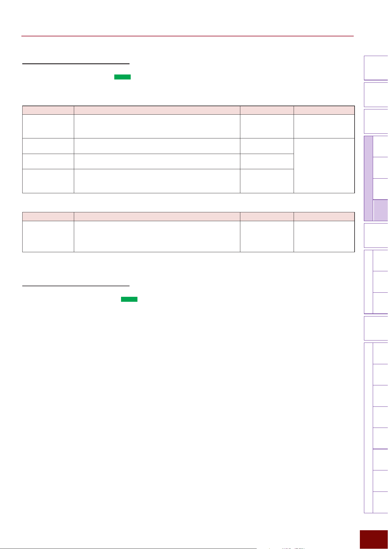
EAD50 EAD20 User Guide
152
Settings in Screens (Parameters)
Modifier
Knobs
LED
Rotary
Faders
[ MIC / TRIG ]
[ SCENE ][ CLICK ][ RECORDER ]
[ MENU ]
MicTriggerKitEffectRecorderLooperSamplingUtilityOutputAux In
USB AudioBluetooth
FileFactory
Reset
Version
[
LIVE SET
]
[F3] Setting "Effect "Ins1 Mic
This product includes 2 blocks of Insertion Effects (Page 29) that can be applied to input sounds from mic jacks. This sets
Insertion1 Effects settings. For the
EAD50
model, the mic jack is selected in the screen displayed by pressing [F1] MicSel
before specifying the setting.
Page 1/2
Parameter Explanation Setting Default Value
On/Off For each jack, this sets whether to apply Insertion Effect 1
effects to mic sounds (On) or not (Off). If the setting is “Off,” it
has the equivalent effect as the Type = Thru setting.
Off, On Always set to “On” for
Preset Scenes (Effect).
Category Selects the Effect type category for Insertion Effect 1.
Refer to the Effect
Type List.
Setting value in Scene
(Effect)
Type Selects the Effect type for Insertion Effect 1.
Refer to the Effect
Type List.
Depth
Sets the degree to which the Effect is applied. Changing this
value will automatically change some values in the parameter
group.
0 – 127
Page 2/2
Parameter Explanation Setting Default Value
Parameter Group
(varies depending
on the insertion
Effect type)
This adjusts the various parameter (setting) values associated
with the current Insertion Effect 1 type.
Refer to the Effect
Type List.
Setting value in Scene
(Effect)
[F3] Setting "Effect "Ins2 Mic
This product includes 2 blocks of Insertion Effects (Page 29) that can be applied to input sounds from mic jacks. This sets
the Insertion2 Effects setting. For the
EAD50
model, the mic jack is selected on the screen displayed by pressing the [F1]
MicSel before specifying the setting.
Setting parameters are the same as on the following screen.
[F3] Setting
"
Effect
"
Ins1 Mic
EAD50 EAD20 User Guide
153
Settings in Screens (Parameters)
Modifier
Knobs
LED
Rotary
Faders
[ MIC / TRIG ]
[ SCENE ][ CLICK ][ RECORDER ]
[ MENU ]
MicTriggerKitEffectRecorderLooperSamplingUtilityOutputAux In
USB AudioBluetooth
FileFactory
Reset
Version
[
LIVE SET
]
[F3] Setting "Effect "Ins Trig
One block of Insertion Effects (Page 29) can be applied to Voices produced based on input signals from Trigger jacks. The
Trigger Input is selected on the screen displayed by pressing the [F1] TrigSel before specifying the setting.
Page 1/2
Parameter Explanation Setting Default Value
On/Off For each Trigger Input, this sets whether to apply Insertion
Effects to Voices sounded based on input signals from
Trigger jacks (On) or not (Off). If the setting is “Off,” it has the
equivalent effect as the Type = Thru setting.
Off, On Always set to “On” for
Preset Scenes (Effect).
Category Selects the Effect type category for each Trigger Input.
Refer to the Effect
Type List.
Setting value in Scene
(Effect)
Type Selects the Effect type for each Trigger Input.
Refer to the Effect
Type List.
Depth For each Trigger Input, this specifies the degree to which
Effects are applied.
0 – 127
Page 2/2
Parameter Explanation Setting Default Value
Parameter Group
(varies depending
on the insertion
Effect type)
For each Trigger Input, this adjusts various parameters
(settings) associated with the current Effect type.
Refer to the Effect
Type List.
Setting value in Scene
(Effect)
[F3] Setting "Effect "Master FX
Master Effects are applied uniformly to overall sounds produced by this product.
Page 1/3
Parameter Explanation Setting Default Value
On/Off Sets whether to apply Master Effects (On) or not (Off). If the
setting is “Off,” it has the equivalent effect as the Type = Thru
setting.
Off, On Always set to “On” for
Preset Scenes (Effect).
Category Selects the Master Effect type category.
Refer to the Effect
Type List.
Setting value in Scene
(Effect)
Type Selects the Master Effect type.
Refer to the Effect
Type List.
Depth Sets the degree (depth) to which Master Effects are applied.
0 – 127
Page 2/3
Parameter Explanation Setting Default Value
Depth Curve
This selects the curve used to determine the depth of Master
Effects based on the overall sound level.
C1 – C7
Setting value in Scene
(Effect)
Page 3/3
Parameter Explanation Setting Default Value
Parameter Group
(varies depending
on Effect type)
This adjusts various parameters (settings) associated with the
current Effect type.
Refer to the Effect
Type List.
Setting value in Scene
(Effect)
EAD50 EAD20 User Guide
154
Settings in Screens (Parameters)
Modifier
Knobs
LED
Rotary
Faders
[ MIC / TRIG ]
[ SCENE ][ CLICK ][ RECORDER ]
[ MENU ]
MicTriggerKitEffectRecorderLooperSamplingUtilityOutputAux In
USB AudioBluetooth
FileFactory
Reset
Version
[
LIVE SET
]
[F3] Setting "Effect "Master Comp
This Compressor is applied uniformly to overall sounds produced by this product.
Page 1/3
Parameter Explanation Setting Default Value
On/Off Sets whether to apply Master Compressor (On) or not (Off). If
the setting is “Off,” it has the equivalent effect as the Type =
Thru setting.
Off, On Always set to “On” for
Preset Scenes (Effect).
Category Selects the Master Compressor type category.
Refer to the Effect
Type List.
Setting value in Scene
(Effect)
Type Selects the Master Compressor type.
Refer to the Effect
Type List.
Depth Sets the degree (depth) to which Master Compressor is
applied.
0 – 127
Page 2/3
Parameter Explanation Setting Default Value
Depth Curve This selects the curve used to determine the depth of Master
Compressor applied based on the overall sound level.
C1 – C7
Setting value in Scene
(Effect)
Page 3/3
Parameter Explanation Setting Default Value
Parameter Group
(varies depending
on Effect type)
This adjusts various parameters (settings) associated with the
current compressor type.
Refer to the Effect
Type List.
Setting value in Scene
(Effect)
[F3] Setting "Effect "Master EQ
This 5-band Equalizers (EQ) are applied uniformly to the overall sound of this product.
NOTE
For more information about equalizers (EQ), refer to the diagrams on Page 32.
Page 1/6
Parameter Explanation Setting Default Value
On/Off Sets whether to apply Master EQ (On) or not (Off). If the
setting is “Off,” it has the equivalent effect as the Type = Thru
setting. This product does not provide a type for Master EQ,
so respective parameter settings must be adjusted to finish
refining the desired sound.
Off, On Always set to “On” for
Preset Scenes (Effect).
Page 2/6
Parameter Explanation Setting Default Value
Low Freq This sets the midpoint of the EQ low frequency band.
32Hz – 2.0kHz
Setting value in Scene
(Effect)
Low Gain Sets the gain level for the EQ low frequency band.
−12dB – 0dB –
+12dB
Low Q This sets the Q factor (frequency characteristics) for the EQ
low frequency band.
If Low Shape is set to LowShelving, then the Low Q value will
have no effect.
0.1 – 12.0
Low Shape This selects the shape of frequency characteristics for the EQ
low frequency band.
LowShelving,
PeakDip
EAD50 EAD20 User Guide
155
Settings in Screens (Parameters)
Modifier
Knobs
LED
Rotary
Faders
[ MIC / TRIG ]
[ SCENE ][ CLICK ][ RECORDER ]
[ MENU ]
MicTriggerKitEffectRecorderLooperSamplingUtilityOutputAux In
USB AudioBluetooth
FileFactory
Reset
Version
[
LIVE SET
]
Page 3/6
Parameter Explanation Setting Default Value
MidLow Freq
This sets the midpoint of the EQ low-to-mid frequency band.
100Hz – 10.0kHz
Setting value in Scene
(Effect)
MidLow Gain Sets the gain level for the EQ low-to-mid frequency band.
−12dB – 0dB –
+12dB
MidLow Q This sets the Q factor (frequency characteristics) for the EQ
low-to-mid frequency band.
0.1 – 12.0
Page 4/6
Parameter Explanation Setting Default Value
Mid Freq
This sets the midpoint of the EQ middle frequency band.
100Hz – 10.0kHz
Setting value in Scene
(Effect)
Mid Gain Sets the gain level for the EQ middle frequency band.
−12dB – 0dB –
+12dB
Mid Q This sets the Q factor (frequency characteristics) for the EQ
middle frequency band.
0.1 – 12.0
Page 5/6
Parameter Explanation Setting Default Value
MidHigh Freq
This sets the midpoint of the EQ mid-to-high frequency band.
100Hz – 10.0kHz
Setting value in Scene
(Effect)
MidHigh Gain Sets the gain level for the EQ
mid-to-high
frequency band.
−12dB – 0dB –
+12dB
MidHigh Q This sets the Q factor (frequency characteristics) for the EQ
mid
-to-high frequency band.
0.1 – 12.0
Page 6/6
Parameter Explanation Setting Default Value
High Freq
This sets the midpoint of the EQ high frequency band.
500Hz – 16.0kHz
Setting value in Scene
(Effect)
High Gain Sets the gain level for the EQ
high
frequency band.
−12dB – 0dB –
+12dB
High Q This sets the Q factor (frequency characteristics) for the EQ
high frequency band.
If High Shape is set to HighShelving, then the High Q value
has no effect.
0.1 – 12.0
High Shape This selects the shape of frequency characteristics for the EQ
high frequency band.
HighShelving,
PeakDip
EAD50 EAD20 User Guide
156
Settings in Screens (Parameters)
Modifier
Knobs
LED
Rotary
Faders
[ MIC / TRIG ]
[ SCENE ][ CLICK ][ RECORDER ]
[ MENU ]
MicTriggerKitEffectRecorderLooperSamplingUtilityOutputAux In
USB AudioBluetooth
FileFactory
Reset
Version
[
LIVE SET
]
[F3] Setting "Effect "Effect Out
This sets how to output performance sounds after processing with System and Master Effects.
Parameter Explanation Setting Default Value
Main Out Selects whether to output performance sounds processed
with System and Master Effects from the [OUTPUT] jacks (On)
or not (Off).
Off, On
Always set to “On” for
Preset Scenes (Effect).
Phones Out Selects whether to output performance sounds processed
with System and Master Effects from the [PHONES] jacks (On)
or not (Off).
Off, On
USB Audio Out1/2 Selects whether to output performance sounds processed
with System and Master Effects from the [USB TO HOST]
terminal (On) or not (Off).
Off, On
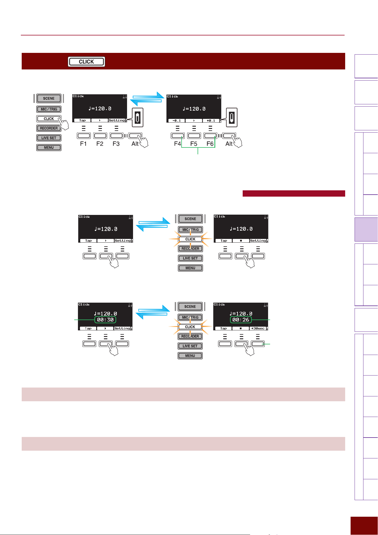
EAD50 EAD20 User Guide
157
Settings in Screens (Parameters)
Modifier
Knobs
LED
Rotary
Faders
[ MIC / TRIG ] [ SCENE ][ CLICK ][ RECORDER ]
[ MENU ]
MicTriggerKitEffectRecorderLooperSamplingUtilityOutputAux In
USB AudioBluetooth
FileFactory
Reset
Version
[
LIVE SET
]
[CLICK]
This screen is used to playback click sounds or specify related settings.
NOTE
The abbreviations “F” (in “F1 – F6”) and
“Alt” refer to “Function” and “Alternative”(for
switching to an alternative), respectively.
They are used to name the buttons for
explanatory convenience. The names are
not printed on the panel.
These increase/decrease tempo values in 0.1 BPM steps.
The [+]/[−] buttons or knob increase/decrease the tempo in
1 BPM steps.
First Second
Setting the Tempo, Playing, and Stopping Clicks
F1 F2 F3 F1 F2 F3
While Clicking is stopped While Clicking is being played
F1 F2 F3 F1 F2 F3
While Clicking is stopped
(timer is set)
While Clicking is being played
(timer is set)
Counts down as a timer.Timer display for setting set
on the following screen.
[CLICK]
"
[F3] Setting
"
Click
"
Timer
Extends the timer setting by
30 seconds.
[+]/[−] Buttons and Knob
Click tempo (BPM) values are set in units of 1.
Setting range: 30.0 to 300.0 Default value: Tempo value registered in Scene
[F4] [F6]
Click tempo (BPM) values are set in units of 0.1.
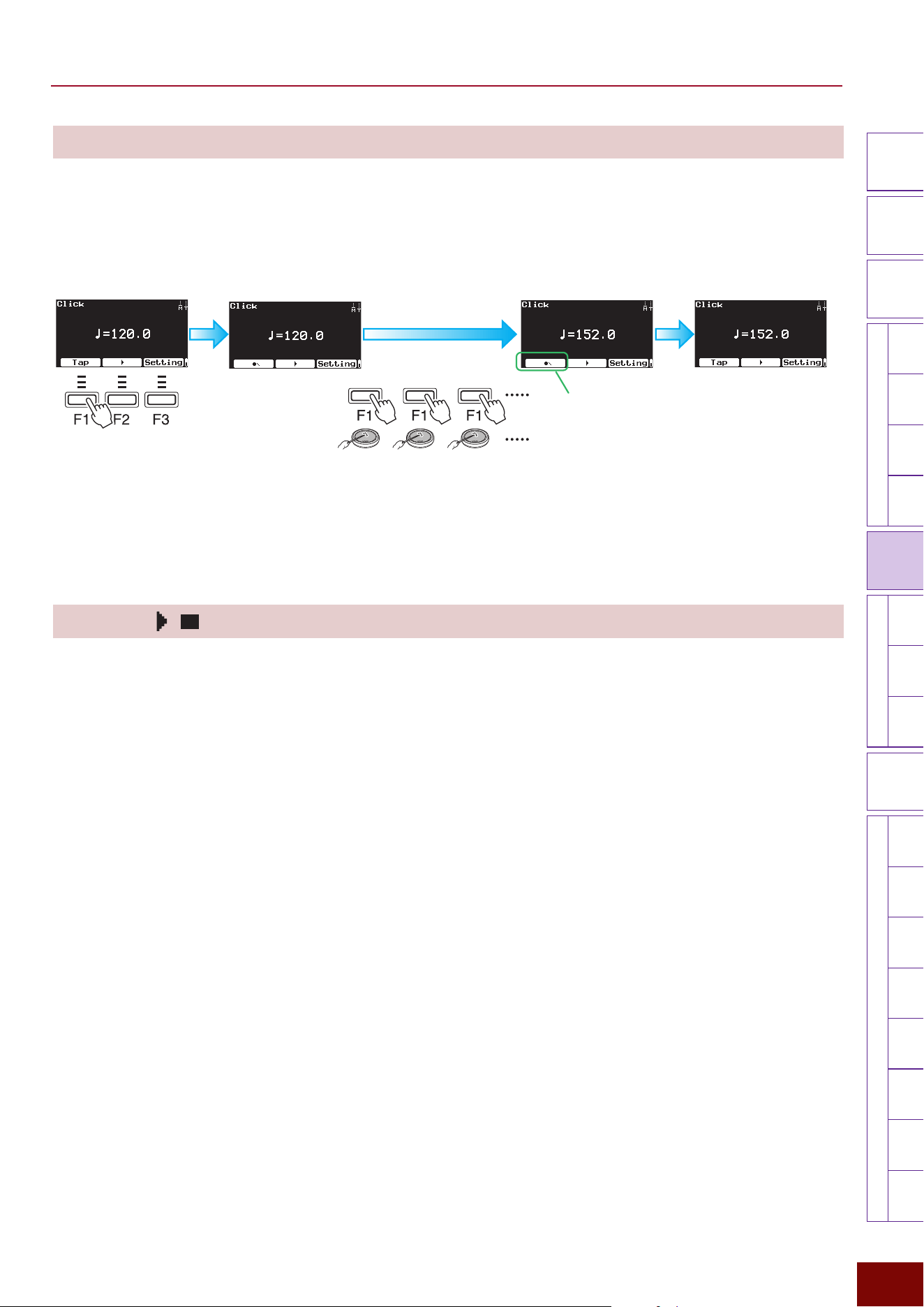
EAD50 EAD20 User Guide
158
Settings in Screens (Parameters)
Modifier
Knobs
LED
Rotary
Faders
[ MIC / TRIG ] [ SCENE ][ CLICK ][ RECORDER ]
[ MENU ]
MicTriggerKitEffectRecorderLooperSamplingUtilityOutputAux In
USB AudioBluetooth
FileFactory
Reset
Version
[
LIVE SET
]
[F1] Tap
This sets the tempo value (BPM) by pressing the [F1] button or hitting an electronic drum pad at any desired tempo. By
pressing the button or hitting the pad in time with the beat of a song or phrase, the Clicks set the desired tempo.
1.
Pressing the [F1] button switches the
corresponding [F1] button to an icon
specifically for tapping.
2.
Tapping the [F1] button at least 3
times sets the tempo value based
on the time interval between taps.
3.
When 3 or more seconds elapse after the [F1]
button or pad was last tapped, the tempo value is
applied and the screen returns to displaying the
previous screen. Pressing the [EXIT] button before
3 seconds elapse restores the previous screen
and applies the new tempo setting.
The corresponding icon displayed for
the [F1] button changes each time the
[F1] button is pressed or the pad is hit.
[F2] [F5]
This starts or stops playing Click sounds.
NOTE
By hitting a pad, Clicks can be played or stopped even when the Click screen is not displayed. Settings are configured with the following
screen.
[MIC/TRIG]
"
[F3] Setting
"
Kit
"
Voice
"
Voice Func
"
Click Start/Stop
NOTE
Separately from the above operation, tempo (BPM) values can also be set by tapping the pad corresponding to the
Trigger Input Source specified on the following screen. That method is enabled even when a screen unrelated to Clicking
is displayed.
[MIC/TRIG]
"
[F3] Setting
"
Kit
"
Voice
"
Voice Func
"
Tempo Tap
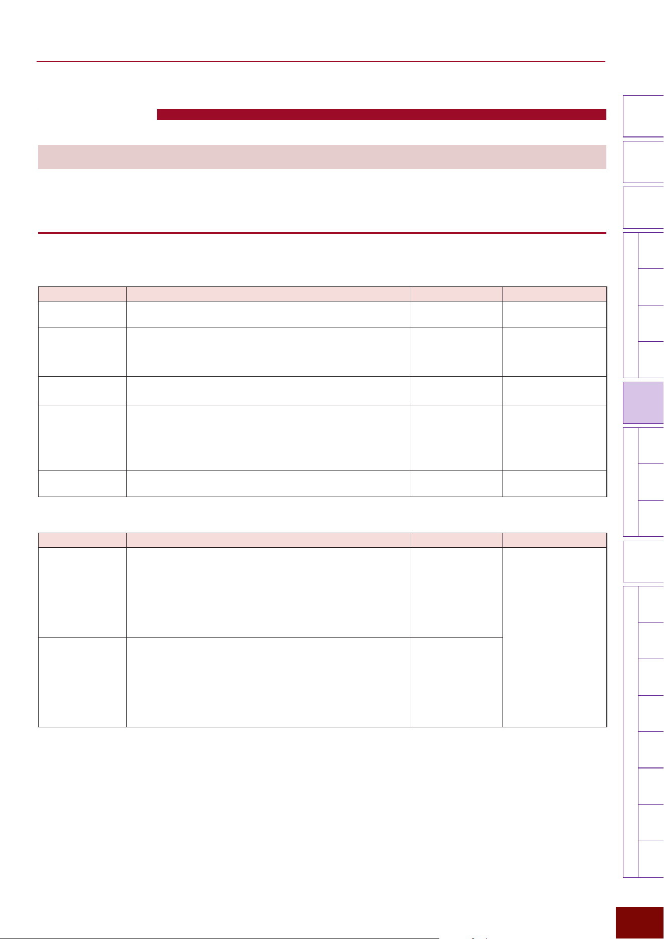
EAD50 EAD20 User Guide
159
Settings in Screens (Parameters)
Modifier
Knobs
LED
Rotary
Faders
[ MIC / TRIG ] [ SCENE ][ CLICK ][ RECORDER ]
[ MENU ]
MicTriggerKitEffectRecorderLooperSamplingUtilityOutputAux In
USB AudioBluetooth
FileFactory
Reset
Version
[
LIVE SET
]
Click Settings
[F3] Setting
This displays the screen for specifying a variety of Click-related settings.
[F3] Setting "Click
Used to specify Click sound settings.
Page 1/4
Parameter Explanation Setting Default Value
Volume Sets the Click volume.
0 – 127 Always set to “100” for
Preset Scenes (Click).
Voice Set This selects the Click Voice.
Metronome1,
Metronome2, Claves,
Cowbell, Shaker,
Stick
Always set to
“Metronome1” for Preset
Scenes (Click).
Beat Sets the beat (and whether to and how often to include
accented beats).
1/4 – 16/4, 1/8 – 16/8,
1/16 – 16/16
Always set to “4/4” for
Preset Scenes (Click).
Human Voice This function counts the beat with a human Voice during Click
playback. For example, if the product is set to 4 beats and
this setting is set to “1”, then “1, 2, 3, 4”, sounds are repeated
for all sections, whereas if it is set to “2”, the pattern “1, 2, 3, 4”
"
“2, 2, 3, 4”
"
“3, 2, 3, 4”
"
“4, 2, 3, 4” is repeated.
Off, 1, 2 Always set to “Off” for
Preset Scenes (Click).
Human Volume This sets the volume of the human Voice.
0 – 127 Always set to “100” for
Preset Scenes (Click).
Page 2/4
Parameter Explanation Setting Default Value
Timer Sets the playback time of Clicks in 30-second increments,
which can be used as a timer. The timer is useful when
practicing for a specified time. The setting specified here
is displayed below the tempo value in the top Click screen.
When the Click is started, “+30 sec” is displayed for the [F3]
button, which increases the timer value by 30 seconds each
time it is pressed.
Off, 00:30 – 60:00 Always set to “Off” for
Preset Scenes (Click).
Count Off This can be used to play Clicks for counting beats before
actually starting to play. In that case, either “1” or “2” can
be specified. If set to “1”, Clicks are played back for one
measure and then stop. If set to “2”, Clicks are played back
for two measures and then stop.
To continue Click playback until the stop operation is
executed, set this to “Off”.
Off, 1, 2
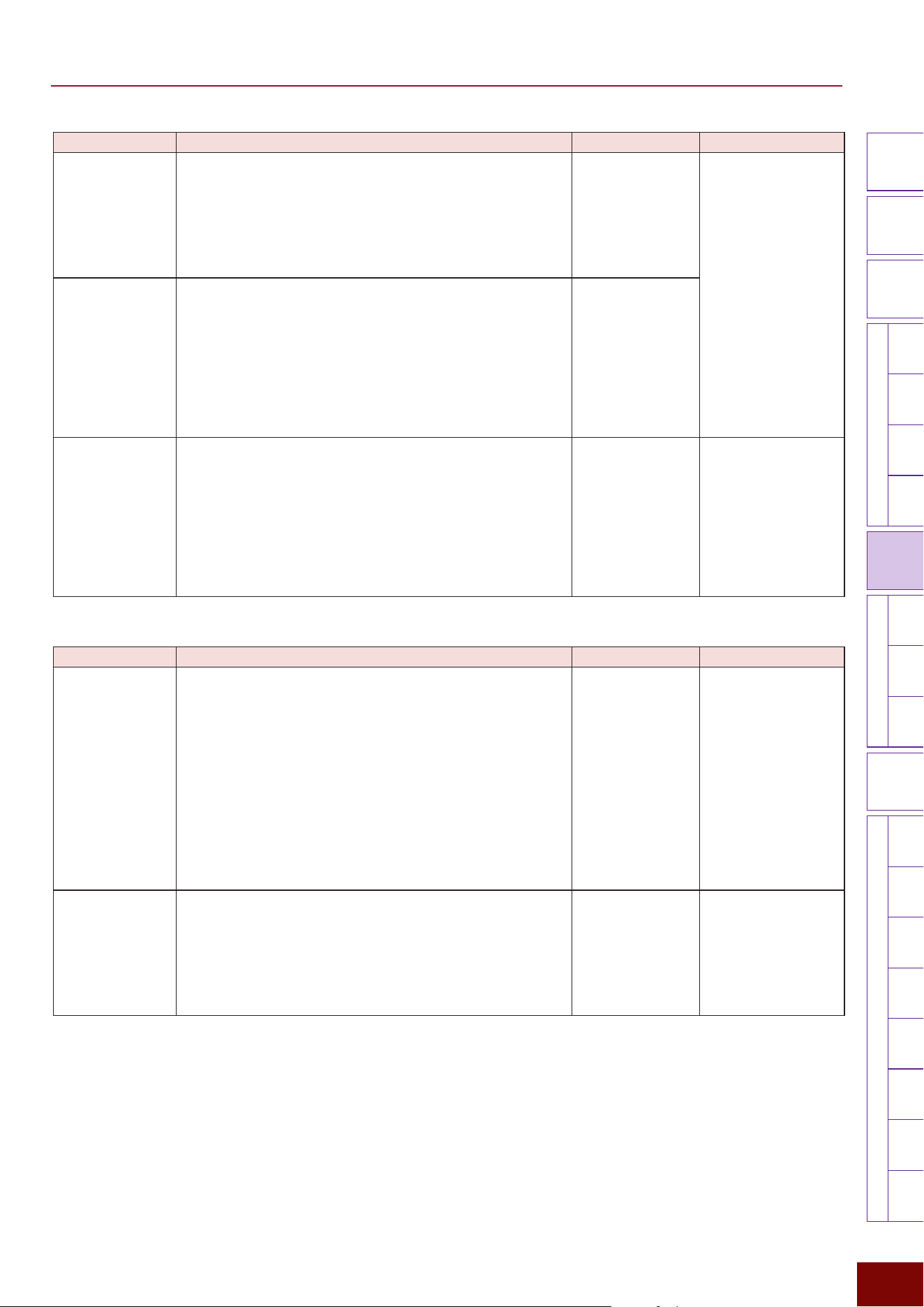
EAD50 EAD20 User Guide
160
Settings in Screens (Parameters)
Modifier
Knobs
LED
Rotary
Faders
[ MIC / TRIG ] [ SCENE ][ CLICK ][ RECORDER ]
[ MENU ]
MicTriggerKitEffectRecorderLooperSamplingUtilityOutputAux In
USB AudioBluetooth
FileFactory
Reset
Version
[
LIVE SET
]
Parameter Explanation Setting Default Value
Recorder Sync This specifies whether to synchronize Clicks with audio file
playback using the Recorder function (On) or not (Off).
If set to “On”, Clicks are synchronized with audio files as soon
as playback is started. That also requires separately setting
a tempo that matches the audio file, using the Offset Time
function to adjust the playback start timing, and setting a Pre
Count value.
Off, On Always set to “Off” for
Preset Scenes (Click).
Pre Count This is only enabled when Recorder Sync = On. It specifies
the number of pre-count measures played back before
starting audio file playback.
If set to “Off”, no pre-count is played back.
If set to “1” or “2”, audio file playback starts after Click
playback for 1 or 2 measures, and Click playback continues.
If set to “1 (Stop)” or “2 (Stop)”, audio file playback starts after
Click playback for 1 or 2 measures and then Click playback
stops.
Off, 1, 1 (Stop), 2,
2 (Stop)
Offset Time This is only enabled when Recorder Sync = On.
When using the Recorder function to synchronize Clicks with
an audio file (the point it actually starts playback), this sets
how long to offset the start time.
By specifying the time between the beginning of the audio
file and the first beat from which playback actually starts, it
is used to eliminate deviation from the Click sound. The beat
timing of the first Click is determined based on this setting
value and pre-count Clicks are added based on that timing.
0 ms –
99 sec 999 ms
Always set to “0 ms” for
Preset Scenes (Click).
Page 3/4
Parameter Explanation Setting Default Value
Category This allows selecting the Click Voice for each beat resolution
(note). This selects the Voice category. When the [F1] NoteSel
button is pressed, the beat resolution (note duration) display
changes in the upper right area of the screen, where the
Voice category is selected individually for each note.
NOTE
The notes selectable using the [F1] NoteSel button differ depending
on the beat.
• If Beat = 1/4 – 16/4: Accent, 4th, 8th, 16th, or 8thTriplet
• If Beat = 1/8 – 16/8: Accent, Dotted4th, 8th, 16th, or 8thTriplet (where
Dotted4th is only enabled for Beat = 3/8, 6/8, 9/8, 12/8, or 15/8)
• If Beat = 1/16 – 16/16: Accent, 4th, 8th, 16th, 8thTriplet
Refer to the Voice
List.
Setting value in Scene
(Click)
Number Allows selecting the Voice used to play back Click sounds for
each beat resolution (each note duration). It selects the Voice
to use from among the Voices in the current Voice category.
When the [F1] NoteSel button is pressed, the beat resolution
(note duration) display changes in the upper right area of the
screen, where the Voice number is selected individually for
each note.
Refer to the Voice
List.
Setting value in Scene
(Click)
EAD50 EAD20 User Guide
161
Settings in Screens (Parameters)
Modifier
Knobs
LED
Rotary
Faders
[ MIC / TRIG ] [ SCENE ][ CLICK ][ RECORDER ]
[ MENU ]
MicTriggerKitEffectRecorderLooperSamplingUtilityOutputAux In
USB AudioBluetooth
FileFactory
Reset
Version
[
LIVE SET
]
Parameter Explanation Setting Default Value
Import Wave Imports Click wave files from external memory for each beat
resolution (each note).
1. With the cursor on “Import Wave”, press [ENTER] button.
2. Use the [F1] NoteSel button to select the resolution (note) to
assign the wave file.
3. Use the [+]/[−] buttons or knob to select one audio file saved
in external memory. If necessary, use the [F3]
button to
preview the audio file.
4. Press the [ENTER] button.
5. When “Are You Sure?” is displayed, press [F1] Yes to import
the file.
— —
Page 4/4
Parameter Explanation Setting Default Value
Note Volume This individually adjusts the volume of each Voice selected for
Click sounds for each beat resolution (each note). Use the (F1)
NoteSel button to select the resolution (note).
0 – 127 Always set to “100” for
Preset Scenes (Click).
Note Pan This individually adjusts the pan position of each Voice
selected for Click sounds for each beat resolution (each note).
Use the (F1) NoteSel button to select the resolution (note).
L63 – C – R63 Always set to “C” for
Preset Scenes (Click).
Note Tuning This is used to tune each Voice selected for Click sounds
individually for each beat resolution (each note). Use the (F1)
NoteSel button to select the resolution (note).
−24.0 – 0.0 – +24.0 Always set to “0.0” for
Preset Scenes (Click).
[F3] Setting "Click "Click EQ
Sets the equalizer (EQ) for playing Click sounds.
NOTE
For more information about equalizers (EQ), refer to the diagrams on Page 32.
Page 1/6
Parameter Explanation Setting Default Value
On/Off Sets whether to apply EQ to Click playback (On) or not (Off).
The “Off” setting is equivalent to Gain = 0 for each frequency
band and HPF Freq = Thru.
Off, On Always set to “Off” for
Preset Scenes (Click).

EAD50 EAD20 User Guide
162
Settings in Screens (Parameters)
Modifier
Knobs
LED
Rotary
Faders
[ MIC / TRIG ] [ SCENE ][ CLICK ][ RECORDER ]
[ MENU ]
MicTriggerKitEffectRecorderLooperSamplingUtilityOutputAux In
USB AudioBluetooth
FileFactory
Reset
Version
[
LIVE SET
]
Page 2/6
Parameter Explanation Setting Default Value
Low Freq This sets the midpoint of the EQ low frequency band.
32Hz – 2.0kHz Always set to “125Hz”
for Preset Scenes (Click).
Low Gain
Used to boost or cut signals near the frequency specified for
Low Freq.
−12dB – 0dB –
+12dB
Always set to “0dB” for
Preset Scenes (Click).
Low Q This sets the Q factor (frequency characteristics) for the EQ
low frequency band. If Low Shape is set to LowShelving, then
the Low Q value will have no effect.
0.1 – 12.0 Always set to “0.9” for
Preset Scenes (Click).
Low Shape This selects the shape of frequency characteristics for the EQ
low frequency band.
LowShelving,
PeakDip
Always set to
“LowShelving” for Preset
Scenes (Click).
Page 3/6
Parameter Explanation Setting Default Value
MidLow Freq This sets the midpoint of the EQ low-to-mid frequency band.
100Hz – 10.0kHz Always set to “500Hz”
for Preset Scenes (Click).
MidLow Gain Used to boost or cut signals near the frequency specified for
MidLow Freq.
−12dB – 0dB –
+12dB
Always set to “0dB” for
Preset Scenes (Click).
MidLow Q This sets the Q factor (frequency characteristics) for the EQ
low-to-mid frequency band.
0.1 – 12.0 Always set to “0.9” for
Preset Scenes (Click).
Page 4/6
Parameter Explanation Setting Default Value
MidHigh Freq This sets the midpoint of the EQ mid-to-high frequency band.
100Hz – 10.0kHz Always set to “4.0Hz” for
Preset Scenes (Click).
MidHigh Gain Used to boost or cut signals near the frequency specified for
MidHigh Freq.
−12dB – 0dB –
+12dB
Always set to “0dB” for
Preset Scenes (Click).
MidHigh Q This sets the Q factor (frequency characteristics) for the EQ
mid-to-high frequency band.
0.1 – 12.0 Always set to “0.9” for
Preset Scenes (Click).
Page 5/6
Parameter Explanation Setting Default Value
High Freq This sets the midpoint of the EQ high frequency band.
500Hz – 16.0kHz Always set to “9.0kHz”
for Preset Scenes
(Click).
High Gain
Used to boost or cut signals near the frequency specified for
High Freq.
−12dB – 0dB –
+12dB
Always set to “0dB” for
Preset Scenes (Click).
High Q This sets the Q factor (frequency characteristics) for the EQ
high frequency band. If High Shape is set to HighShelving,
then the High Q value has no effect.
0.1 – 12.0 Always set to “0.9” for
Preset Scenes (Click).
High Shape This selects the shape of frequency characteristics for the EQ
high frequency band. If LPF is selected, the entire equalizer
changes to functioning as a low-pass filter.
HighShelving,
PeakDip, LPF
Always set to
“HighShelving” for Preset
Scenes (Click).
Page 6/6
Parameter Explanation Setting Default Value
HPF Freq
Separately from EQ settings, a high-pass filter (HPF) can
also be applied to Click playback. The filter cuts sounds with
frequencies lower than the specified frequency. If “Thru” is
specified, the HPF is not applied.
Thru, 56Hz –
2.0kHz
Always set to “Thru” for
Preset Scenes (Click).
HPF Q This sets the Q factor (frequency characteristics) for the high-
pass filter.
0.1 – 12.0 Always set to “0.7” for
Preset Scenes (Click).
EAD50 EAD20 User Guide
163
Settings in Screens (Parameters)
Modifier
Knobs
LED
Rotary
Faders
[ MIC / TRIG ] [ SCENE ][ CLICK ][ RECORDER ]
[ MENU ]
MicTriggerKitEffectRecorderLooperSamplingUtilityOutputAux In
USB AudioBluetooth
FileFactory
Reset
Version
[
LIVE SET
]
[F3] Setting "Click "Click Out
Sets the jack used to output Click playback sounds.
Page 1/2
Parameter Explanation Setting Default Value
Main Out This sets whether to output Click sounds from [OUTPUT] jacks
(On) or not (Off).
Off, On Always set to “On” for
Preset Scenes (Click).
Phones Out This sets whether to output Click sounds from [PHONES]
jacks (On) or not (Off).
Off, On
USB Audio Out
1/2
This sets whether to output Click sounds from the [USB TO
HOST] terminal (On) or not (Off).
Off, On
Page 2/2
Parameter Explanation Setting Default Value
IndivOut
(
EAD50
only)
This sets whether to use the left (L) or right (R) channel
([INDIVIDUAL OUTPUT] jacks) for external output of Click
sounds.
Off, L1+R2, L3+R4,
L5+R6, L7+R8,
L1, R2, L3, R4, L5,
R6, L7, R8, (L+R)1,
(L+R)2, (L+R)3,
(L+R)4, (L+R)5,
(L+R)6, (L+R)7,
(L+R)8
* For a description of
respective setting
values, refer to the
table at the bottom of
Page 116.
Always set to “Off” for
Preset Scenes (Click).
IndivOut Vol
(
EAD50
only)
Sets the volume of Click sounds output from [INDIVIDUAL
OUTPUT] jacks. If “Variable” is specified, the volume is linked
to [CLICK] slider operations.
Variable, 1 – 127 Always set to “Variable”
for Preset Scenes (Click).
USB AudOut
(
EAD20
only)
This sets whether to use the left (L) or right (R) channel for
external output of Click sounds via a USB cable.
Off, L3+R4, L5+R6,
L7+R8, L9+R10, L3,
R4, L5, R6, L7, R8,
L9, R10, (L+R)3,
(L+R)4, (L+R)5,
(L+R)6, (L+R)7,
(L+R)8, (L+R)9,
(L+R)10
* For a description of
respective setting
values, refer to the
table at the bottom of
Page 117.
Always set to “Off” for
Preset Scenes (Click).
USB AudOut Vol
(
EAD20
only)
This adjusts the volume for external output of Click sounds via
a USB cable. If “Variable” is specified, the volume is linked to
[MASTER] knob operations.
Variable, 1 – 127 Always set to “Variable”
for Preset Scenes (Click).
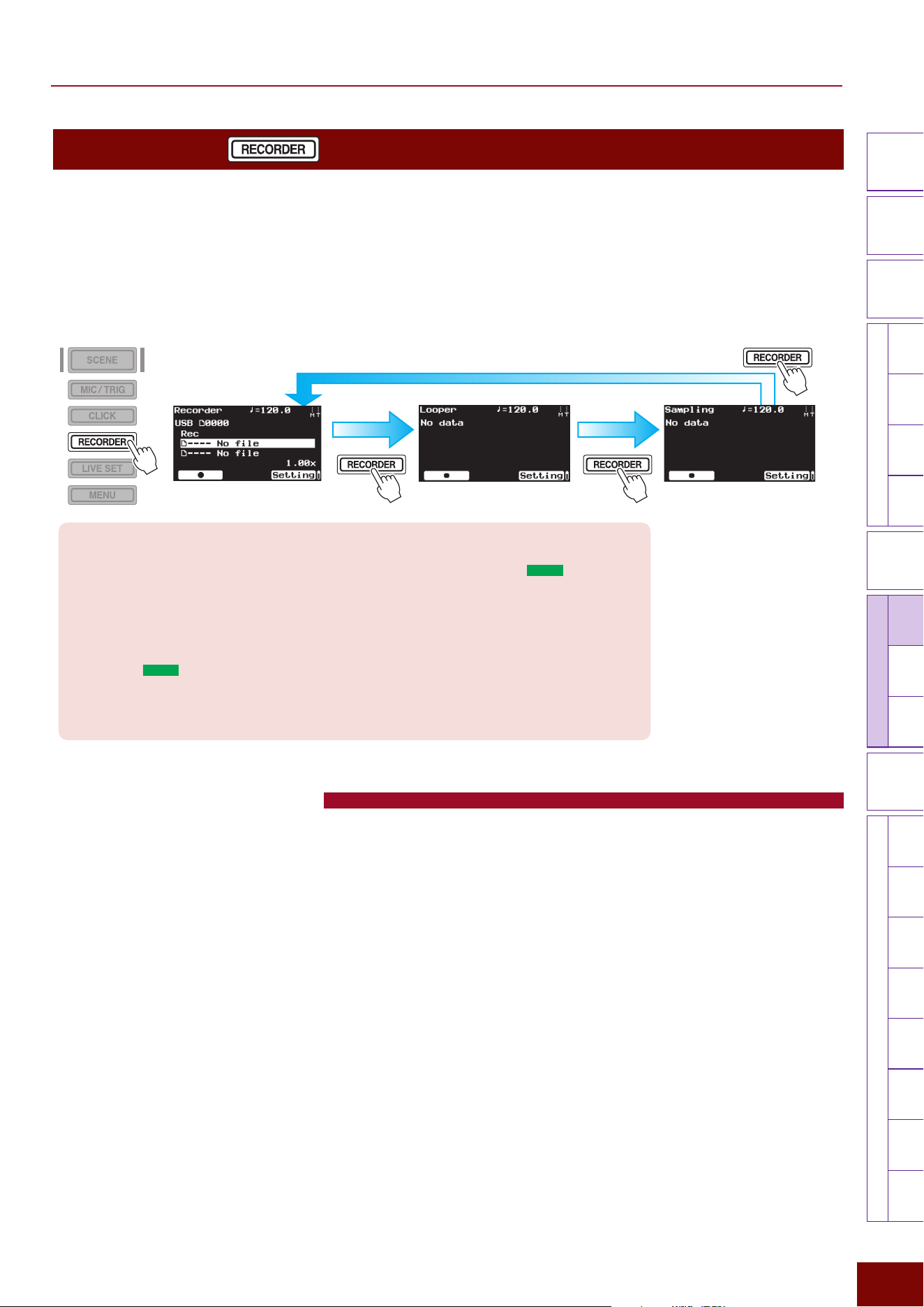
EAD50 EAD20 User Guide
164
Settings in Screens (Parameters)
Modifier
Knobs
LED
Rotary
Faders
[ MIC / TRIG ] [ SCENE ][ CLICK ]
[ RECORDER ]
[ MENU ]
MicTriggerKitEffect
Recorder
LooperSamplingUtilityOutputAux In
USB AudioBluetooth
FileFactory
Reset
Version
[
LIVE SET
]
[RECORDER]
Successively pressing the [RECORDER] button displays the following three screens.
z
Recorder:
Functionality for recording performances or playing audio files.
z
Looper:
Functionality for continuously playing a recorded loop of performance while playing or recording performances over the loop.
z
Sampling:
After recording a performance, this function is used to load the recording as a User Voice.
NOTE
For more information about the
internal memory structure in the
product related to recording,
refer to Page 33.
Important
Saving data recorded by Recorder, Looper, or Sampling functions requires connecting a USB flash
drive to the [USB TO DEVICE] jack or inserting an SD card into the SD card slot (
EAD50
only).
• Looper and Sampling functions use such storage media (external memory) to save the data
recorded in internal memory.
• In contrast, the Recorder function records the data directly in such media. The Recorder function
can also save the data by first recording it in internal memory and then saving it in storage media
(external memory).
• For the
EAD50
model, if both a USB flash drive and SD card are connected, then the operator
must select which media to use. In that case, whenever “MemSel” or “USB/SD” is displayed at the
bottom of respective function screens, select the type of media by pressing the corresponding F
button.
[RECORDER]-Recorder
Pressing the [RECORDER] button several times opens the Recorder screen. The Recorder includes the following two functions.
z
Playback Function
This can be used to select and play an audio file saved in external memory. Up to 2 files stored on the same media can be
played back at the same time.
For example, the ability to play 2 files at the same time allows a song that cannot be synchronized with the internal Click, due
to tempo changes midway through the song, to be used as a backing track for performances (or for practice), by using each
file for different purposes, as indicated below.
• Play one file as audio data (backing data) for the song itself.
• Play the other file as guiding audio data (for playing back Clicks according to the specified tempo setting for the song,
including the tempo changes part way through the song).
If they listen to the guiding data while playing, it enables the performer to perform the song with the correct tempo.
Furthermore, the guiding data should probably be output only from the [PHONES] jack.
z
Record Function
This can be used to record in external memory not only one’s own performances, of course, but also audio sounds input via a
variety of jacks. If no external memory is connected, then the audio is recorded in internal memory.
NOTE
To switch audio files each time a Scene is selected, set [SCENE]
"
[F3] Setting
"
Scene Load
"
Recorder = On. The default factory setting is
“Off”, which results in not switching the audio file even if the Scene is switched.
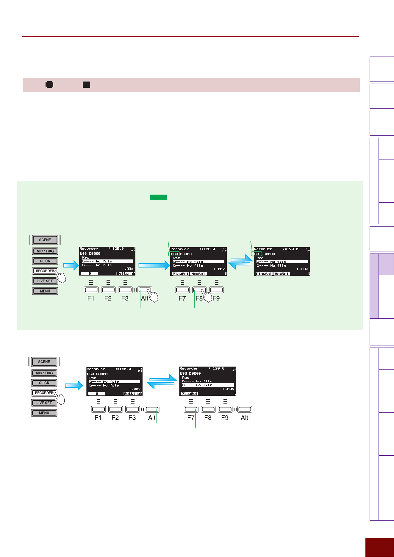
EAD50 EAD20 User Guide
165
Settings in Screens (Parameters)
Modifier
Knobs
LED
Rotary
Faders
[ MIC / TRIG ] [ SCENE ][ CLICK ]
[ RECORDER ]
[ MENU ]
MicTriggerKitEffect
Recorder
LooperSamplingUtilityOutputAux In
USB AudioBluetooth
FileFactory
Reset
Version
[
LIVE SET
]
■ Recording audio or saving data
[F1]
/ [F1]
This collectively records your own performances or audio files played back from an external device in internal or external
memory. After making the necessary connections and preparations, press the [F1] button to start recording and then [F1]
again to stop recording when the performance is finished.
NOTE
For information about internal memory used by the Recorder function, refer to Page 33.
NOTICE
Audio can only be recorded in internal memory one time. The next time audio is recorded, the previous recording is deleted by overwriting.
Also note that audio recorded in internal memory is deleted without backing it up when the power is switched Off. Therefore, to save the audio
recorded in internal memory, connect an external memory device and then use the [F9] Save button.
1 Selecting media (external memory) (
EAD50
only)
If both a USB flash drive and SD card are connected, then the operator must select which media (external memory) to
use.
1. Press 2 times. 2. Pressing the [F8] button
toggles between media.
Indicates that this product will use
the USB flash drive.
Indicates that this product can
use the SD cards.
2 Selecting the Recorder (Playback Device) (Switching between 1 and 2)
NOTE
The abbreviations “F” (in “F1 – F9”) and
“Alt” refer to “Function” and “Alternative” (for
switching to an alternative), respectively.
They are used to name the buttons for
explanatory convenience. The names are
not printed on the panel.
1. Press 2 times.
2. Each press toggles between
Recorders (playback devices)
1 and 2.
3. Pressing 1 time restores the
screen previously displayed.
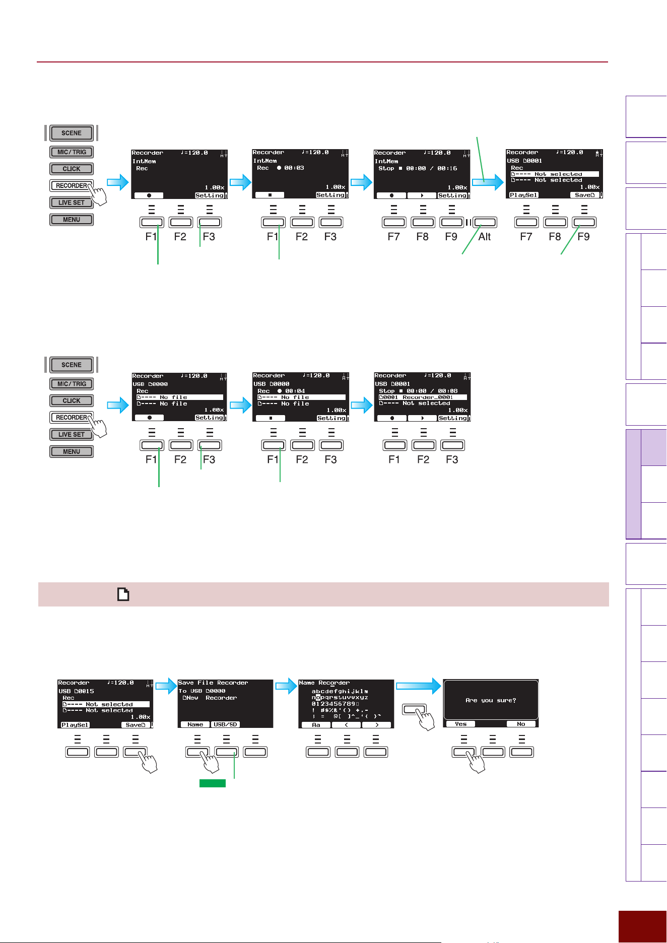
EAD50 EAD20 User Guide
166
Settings in Screens (Parameters)
Modifier
Knobs
LED
Rotary
Faders
[ MIC / TRIG ] [ SCENE ][ CLICK ]
[ RECORDER ]
[ MENU ]
MicTriggerKitEffect
Recorder
LooperSamplingUtilityOutputAux In
USB AudioBluetooth
FileFactory
Reset
Version
[
LIVE SET
]
3 Recording in Internal Memory (If No External Memory is Connected)
1. Configure required settings.
3. Finish recording.
2.
Start recording.
During recording, the
[RECORDER] button is lit red.
4. Press 2 times.
5. Connect an external memory device.
6. Save the recording in external
memory.
Refer to [F9] Save.
Before recording During recording After recording
3 Recording in External Memory (If External Memory is Selected)
[F9] Save
Data recorded in the product’s internal memory can be saved in external memory as a WAV file by pressing the [F9] button.
Saving data from internal memory in media
F1 F2 F3 F1 F2 F3F1 F2 F3
ENTER
F7 F8 F9
After recording Save screen Edit file name
Save the file in external memory
Use the [F2]/[F3] buttons to move
the file name cursor and then use
the [+]/[−] buttons or knob to select
the characters to enter. For more
information, refer to Page 66.
Press 2 times.
For the
EAD50
model,
select the media (USB
flash drive or SD card) as
necessary.
1. Configure required
settings.
3. Finish recording.
2. Start recording.
During recording, the [RECORDER]
button is lit red.
Before recording During recording After recording
The recording is saved as an
automatically named WAV
file.
NOTE
Recording automatically generates a new audio file. The
new file will not overwrite (delete) existing files.
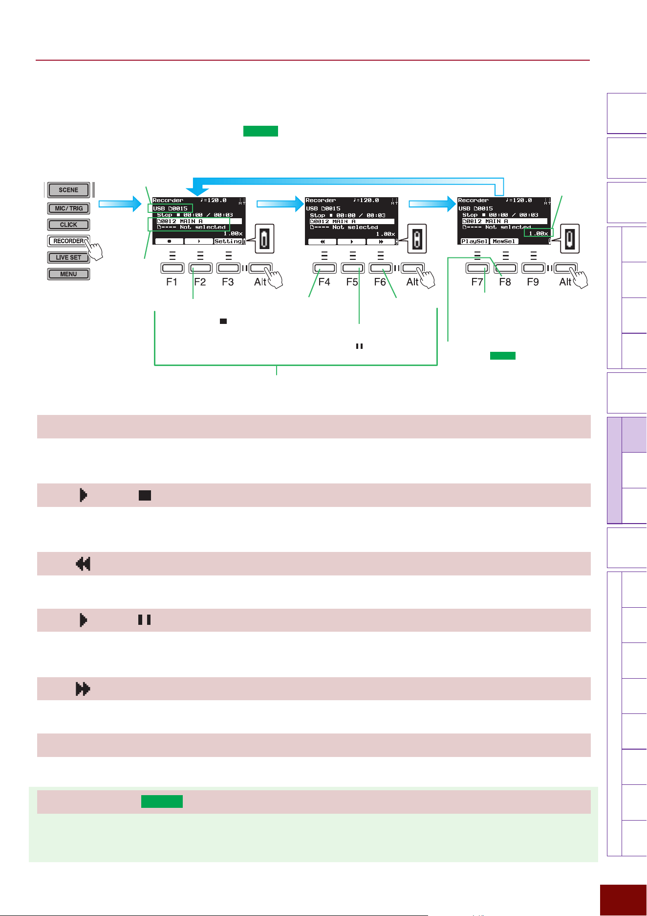
EAD50 EAD20 User Guide
167
Settings in Screens (Parameters)
Modifier
Knobs
LED
Rotary
Faders
[ MIC / TRIG ] [ SCENE ][ CLICK ]
[ RECORDER ]
[ MENU ]
MicTriggerKitEffect
Recorder
LooperSamplingUtilityOutputAux In
USB AudioBluetooth
FileFactory
Reset
Version
[
LIVE SET
]
■ Selecting/Playing Audio Files
Audio data (WAV files) saved in external memory can be played back using the following operations.
1. Select the media (external memory) (
EAD50
only).
2. Select the file in the corresponding Recorder (playback device).
3. Play the file.
[−]/[+] (2. Select the audio file for the currently selected Recorder.)
The operations are enabled only if an external memory device is connected. Press the [F7] button to select an audio file
playback device and then selected the desired audio file.
[F2] / [F2] (3. Play/stop the audio file.)
This plays back the one or two audio files selected. If the button is pressed again during playback, it stops playback and resets the
playback position.
[F4]
This rewinds the one or two audio files selected.
[F5] / [F5] (3. Start or pause the audio file.)
This plays back the one or two audio files selected. If the button is pressed again during playback, it stops playback at the current
playback position.
[F6]
This fast forwards the one or two audio files selected.
[F7] PlaySel (2. Select the Recorder.)
This selects the audio playback device.
[F8] MemSel (
EAD50
only) (1. Select the memory device.)
This is displayed if both a USB flash drive and SD card are connected. It selects which media (external memory) to use.
2. Select the Recorder (playback
device) and select the file. With 2
playback devices available, up to
2 files can be played back at the
same time.
This is the Play button.
During playback, the button symbol
changes to “
” and the button
functions as a Pause button.
This is the Play button.
During playback, the button
symbol changes to “
” and the
button functions as a Stop button.
This functions
as a fast-forward
button.
This functions as
a rewind button.
NOTE
The abbreviations “F” (in “F1 –
F9”) and “Alt” refer to “Function”
and “Alternative” (for switching
to an alternative), respectively.
They are used to name the
buttons for explanatory
convenience. The names are
not printed on the panel.
SecondFirst
Third
Playback speed
Media and number of files
saved in media
Two Recorders
(playback
devices)
1. Select the storage medium (external
memory). (
EAD50
only)
NOTE
If two Recorders (playback devices) are available and files are
selected, they will play the files simultaneously. In that case, the
playback will stop after the shorter file is finished playing.
3. Press the [F2] or [F5] button to start playback.
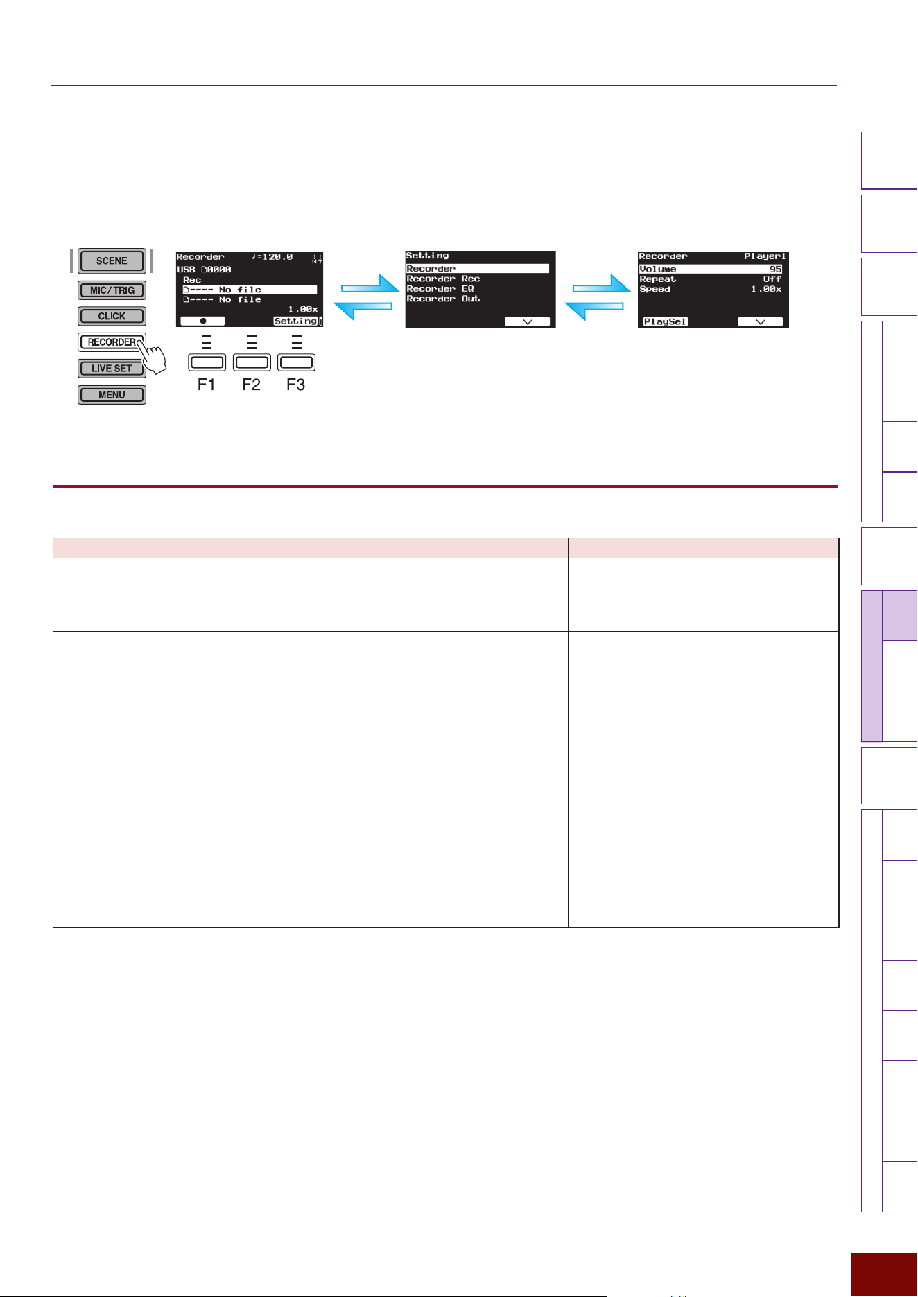
EAD50 EAD20 User Guide
168
Settings in Screens (Parameters)
Modifier
Knobs
LED
Rotary
Faders
[ MIC / TRIG ] [ SCENE ][ CLICK ]
[ RECORDER ]
[ MENU ]
MicTriggerKitEffect
Recorder
LooperSamplingUtilityOutputAux In
USB AudioBluetooth
FileFactory
Reset
Version
[
LIVE SET
]
■ Configuring Recorder-related settings ([F3] Setting)
Pressing the [F3] Setting button on the top screen displays the group of settings related to recording. Because they are located
on multiple hierarchical levels, press [ENTER] to move down a level or [EXIT] to move back up a level to find the desired
setting parameter.
[F3] Setting "Recorder
This is used to specify basic settings for playing back recorded audio data.
Parameter Explanation Setting Default Value
Volume This is used to adjust the volume balance between the
individually set volume levels for the two Recorders (playback
devices). Press the [F1] PlaySel button to select the Recorder
and then specify a numeric value.
0 – 127 Always set to “100”
for Preset Scenes
(Recorder).
Repeat This sets the method used to play back audio files. The same
setting is applied to both Recorders (playback devices).
Off
Playback automatically stops after the currently selected file
is played back one time.
Single
This keeps playing back the currently selected file until the
Stop button is pressed.
List
This successively plays back, in order, all recognizable audio
files in the root directory of the external memory device.
Playback is continued until the Stop button is pressed.
Off, Single, List
Always set to “Off”
for Preset Scenes
(Recorder).
Speed This sets the playback speed for audio files. With a setting
of “1.00x” for the original data, a larger value results in faster
playback and a smaller value results in slower playback. The
same setting is applied to both Recorders (playback devices).
0.50x – 1.50x Always set to “1.00x”
for Preset Scenes
(Recorder).
[EXIT] button
[ENTER] button
[EXIT] button
[F3] button
NOTE
The “F” in “F1 – F3” refers to “Function” and is used to name the buttons
for explanatory convenience. The names are not printed on the panel.
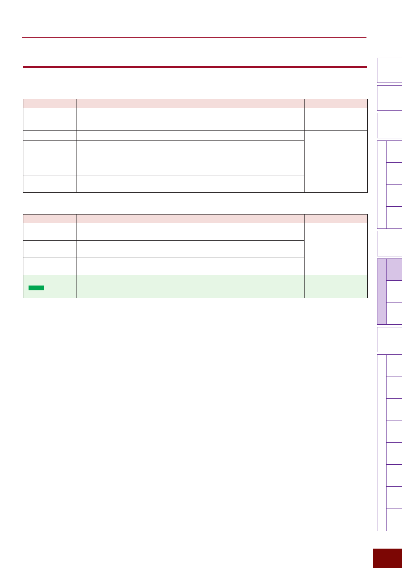
EAD50 EAD20 User Guide
169
Settings in Screens (Parameters)
Modifier
Knobs
LED
Rotary
Faders
[ MIC / TRIG ] [ SCENE ][ CLICK ]
[ RECORDER ]
[ MENU ]
MicTriggerKitEffect
Recorder
LooperSamplingUtilityOutputAux In
USB AudioBluetooth
FileFactory
Reset
Version
[
LIVE SET
]
[F3] Setting "Recorder Rec
This is used to set parameter settings for recording audio.
Page 1/2
Parameter Explanation Setting Default Value
Rec Gain This sets the gain (volume level) for recording audio.
−18dB, −12dB,
−6dB, 0dB, +6dB,
+12dB, +18dB
Always set to “0dB”
for Preset Scenes
(Recorder).
Rec Click Sets whether to record Clicks (On) or not (Off).
Off, On Always set to “On”
for Preset Scenes
(Recorder).
Rec Aux In This sets whether to record the audio being input via the [AUX
IN] jack (On) or not (Off).
Off, On
Rec USB Audio
In1/2
This sets whether to record audio channels 1/2 being input via
the [USB TO HOST] terminal (On) or not (Off).
Off, On
Rec USB Audio
In3/4
This sets whether to record audio channels 3/4 being input via
the [USB TO HOST] terminal (On) or not (Off).
Off, On
Page 2/2
Parameter Explanation Setting Default Value
Rec USB Audio
In5/6
This sets whether to record audio channels 5/6 being input via
the [USB TO HOST] terminal (On) or not (Off).
Off, On Always set to “On”
for Preset Scenes
(Recorder).
Rec USB Audio
In7/8
This sets whether to record audio channels 7/8 being input via
the [USB TO HOST] terminal (On) or not (Off).
Off, On
Rec Recorder
Play
This sets whether to record the Recorder playback sound (On)
or not (Off).
Off, On
Rec Bluetooth
(
EAD50
only)
This sets whether to record the audio being input via Bluetooth
(On) or not (Off).
Off, On Always set to “On”
for Preset Scenes
(Recorder).
EAD50 EAD20 User Guide
170
Settings in Screens (Parameters)
Modifier
Knobs
LED
Rotary
Faders
[ MIC / TRIG ] [ SCENE ][ CLICK ]
[ RECORDER ]
[ MENU ]
MicTriggerKitEffect
Recorder
LooperSamplingUtilityOutputAux In
USB AudioBluetooth
FileFactory
Reset
Version
[
LIVE SET
]
[F3] Setting "Recorder EQ
This sets the EQ (equalizer) settings for audio file playback individually for each Recorder (playback device).
Press the [F1] PlaySel button to select the Recorder (playback device) before setting the Recorder EQ setting.
NOTE
For more information about equalizers (EQ), refer to the diagrams on Page 32.
Page 1/6
Parameter Explanation Setting Default Value
On/Off This sets whether EQ is applied to audio during playback (On)
or not (Off).
The “Off” setting is equivalent to Gain = 0 for each frequency
band and HPF Freq = Thru.
Off, On Always set to “Off”
for Preset Scenes
(Recorder).
Page 2/6
Parameter Explanation Setting Default Value
Low Freq This sets the midpoint of the EQ low frequency band.
32Hz – 2.0kHz Always set to “125Hz”
for Preset Scenes
(Recorder).
Low Gain Used to boost or cut signals near the frequency specified for
Low Freq.
−12dB – 0dB –
+12dB
Always set to “0dB”
for Preset Scenes
(Recorder).
Low Q This sets the Q factor (frequency characteristics) for the EQ
low frequency band. If Low Shape is set to LowShelving, then
the Low Q value will have no effect.
0.1 – 12.0 Always set to “0.9”
for Preset Scenes
(Recorder).
Low Shape This selects the shape of frequency characteristics for the EQ
low frequency band.
LowShelving,
PeakDip
Always set to
“LowShelving” for Preset
Scenes (Recorder).
Page 3/6
Parameter Explanation Setting Default Value
MidLow Freq
This sets the midpoint of the EQ low-to-mid frequency band.
100Hz – 10.0kHz Always set to “500Hz”
for Preset Scenes
(Recorder).
MidLow Gain Used to boost or cut signals near the frequency specified for
MidLow Freq.
−12dB – 0dB –
+12dB
Always set to “0dB”
for Preset Scenes
(Recorder).
MidLow Q This sets the Q factor (frequency characteristics) for the EQ
low-to-mid frequency band.
0.1 – 12.0 Always set to “0.9”
for Preset Scenes
(Recorder).
EAD50 EAD20 User Guide
171
Settings in Screens (Parameters)
Modifier
Knobs
LED
Rotary
Faders
[ MIC / TRIG ] [ SCENE ][ CLICK ]
[ RECORDER ]
[ MENU ]
MicTriggerKitEffect
Recorder
LooperSamplingUtilityOutputAux In
USB AudioBluetooth
FileFactory
Reset
Version
[
LIVE SET
]
Page 4/6
Parameter Explanation Setting Default Value
MidHigh Freq
This sets the midpoint of the EQ low-to-high frequency band.
100Hz – 10.0kHz Always set to “4.0Hz”
for Preset Scenes
(Recorder).
MidHigh Gain Used to boost or cut signals near the frequency specified for
MidHigh Freq.
−12dB – 0dB –
+12dB
Always set to “0dB”
for Preset Scenes
(Recorder).
MidHigh Q This sets the Q factor (frequency characteristics) for the EQ
mid-to-high frequency band.
0.1 – 12.0 Always set to “0.9”
for Preset Scenes
(Recorder).
Page 5/6
Parameter Explanation Setting Default Value
High Freq
This sets the midpoint of the EQ high frequency band.
500Hz – 16.0kHz Always set to “9.0kHz”
for Preset Scenes
(Recorder).
High Gain
Used to boost or cut signals near the frequency specified for
High Freq.
−12dB – 0dB –
+12dB
Always set to “0dB”
for Preset Scenes
(Recorder).
High Q This sets the Q factor (frequency characteristics) for the EQ
high frequency band. If High Shape is set to HighShelving,
then the High Q value has no effect.
0.1 – 12.0 Always set to “0.9”
for Preset Scenes
(Recorder).
High Shape This selects the shape of frequency characteristics for the EQ
high frequency band. If LPF is selected, the entire equalizer
changes to functioning as a low-pass filter.
HighShelving,
PeakDip, LPF
Always set to
“HighShelving” for Preset
Scenes (Recorder).
Page 6/6
Parameter Explanation Setting Default Value
HPF Freq
Separately from EQ settings, a high-pass filter (HPF) can also
be applied to Recorder playback. The filter cuts sounds with
frequencies lower than the specified frequency. If “Thru” is
specified, the HPF is not applied.
Thru, 56Hz –
2.0kHz
Always set to “Thru”
for Preset Scenes
(Recorder).
HPF Q This sets the Q factor (frequency characteristics) for the high-
pass filter.
0.1 – 12.0 Always set to “0.7”
for Preset Scenes
(Recorder).
EAD50 EAD20 User Guide
172
Settings in Screens (Parameters)
Modifier
Knobs
LED
Rotary
Faders
[ MIC / TRIG ] [ SCENE ][ CLICK ]
[ RECORDER ]
[ MENU ]
MicTriggerKitEffect
Recorder
LooperSamplingUtilityOutputAux In
USB AudioBluetooth
FileFactory
Reset
Version
[
LIVE SET
]
[F3] Setting "Recorder Out
This sets output settings for each Recorder (playback device) used to playback audio data (WAV files). Press the [F1] PlaySel
button to select the Recorder (playback device) before setting the Recorder EQ setting.
Page 1/2
Parameter Explanation Setting Default Value
Mode This specifies how to process audio files currently being
played back for output.
Stereo
Processes stereo input sounds directly as stereo output.
L Mono
Uses only sound from the left channel.
R Mono
Uses only sound from the right channel.
L+R Mono (L+R Monaural)
Mixes the left and right channels and processes it as
monaural sound.
L Guide
Select this setting to play audio files in which the guide (click)
sound is on the L channel and the backing sound is on the
R channel. The guide (click) sound and backing sound are
output from the [PHONES] jack in the center pan position,
and the backing sound is output from the [OUTPUT] jacks
and [USB TO HOST] terminal in the center pan position. This
adjusts the volume level of audio output via the [PHONES]
jacks.
EAD50
:
[AUDIO] Slider (backing) and [CLICK] slider (guide)
EAD20
:
[AUDIO/CLICK] knob
R Guide
Select this setting to play the audio file in which the guide
(click) sound is on the R channel and backing sound is on
the L channel. The guide (click) sound and backing sound
are output from the [PHONES] jack in the center pan position,
and the backing sound is output from the [OUTPUT] jacks
and [USB TO HOST] terminal in the center pan position. This
adjusts the volume level of audio output via the [PHONES]
jacks.
EAD50
:
[AUDIO] Slider (backing) and [CLICK] slider (guide)
EAD20
:
[AUDIO/CLICK] knob
Stereo, L Mono, R
Mono, L+R Mono, L
Guide, R Guide
Always set to “Stereo”
for Preset Scenes
(Recorder).
Main Out This sets whether to output audio files currently being played
back from [OUTPUT] jacks (On) or not (Off).
Off, On Always set to “On”
for Preset Scenes
(Recorder).
Phones Out This sets whether to output audio files currently being played
back from [PHONES] jacks (On) or not (Off).
Off, On
USB Audio Out
1/2
This sets whether to output audio files currently being played
back from the [USB TO HOST] terminal (On) or not (Off).
Off, On
Backing Out Level
The setting is displayed when Mode = L Guide or R Guide.
This sets the volume level for backing sound output via the
[OUTPUT] jacks and [USB TO HOST] terminal (USB Audio 1/2).
0 – 127 Always set to “127”
for Preset Scenes
(Recorder).
EAD50 EAD20 User Guide
173
Settings in Screens (Parameters)
Modifier
Knobs
LED
Rotary
Faders
[ MIC / TRIG ] [ SCENE ][ CLICK ]
[ RECORDER ]
[ MENU ]
MicTriggerKitEffect
Recorder
LooperSamplingUtilityOutputAux In
USB AudioBluetooth
FileFactory
Reset
Version
[
LIVE SET
]
Page 2/2
Parameter Explanation Setting Default Value
IndivOut
(
EAD50
only)
This specifies which channel ([INDIVIDUAL OUTPUT] jacks)
to use for external output of left (L) and right (R) channels of
audio files currently being played back.
Off, L1+R2, L3+R4,
L5+R6, L7+R8,
L(1+2), R(1+2),
L(3+4), R(3+4),
L(5+6), R(5+6),
L(7+8), R(7+8),
L1, R2, L3, R4, L5,
R6, L7, R8, (L+R)1,
(L+R)2, (L+R)3,
(L+R)4, (L+R)5,
(L+R)6, (L+R)7,
(L+R)8
* For a description of
respective setting
values, refer to the
table at the bottom of
Page 116.
Always set to “Off”
for Preset Scenes
(Recorder).
IndivOut Vol
(
EAD50
only)
Sets the volume level for output from [INDIVIDUAL OUTPUT]
jacks of audio played back using this function. If “Variable” is
specified, the volume is linked to [AUDIO] slider operations.
Variable, 1 – 127 Always set to “Variable”
for Preset Scenes
(Recorder).
USB AudOut
(
EAD20
only)
This sets whether to use the left (L) or right (R) channel for
external output of audio file playback (L+R) via a USB cable.
Off, L3+R4, L5+R6,
L7+R8, L9+R10, L3,
R4, L5, R6, L7, R8,
L9, R10, (L+R)3,
(L+R)4, (L+R)5,
(L+R)6, (L+R)7,
(L+R)8, (L+R)9,
(L+R)10
* For a description of
respective setting
values, refer to the
table at the bottom of
Page 117.
Always set to “Off”
for Preset Scenes
(Recorder).
USB AudOut Vol
(
EAD20
only)
This adjusts the volume for external output of audio file playback
sounds via a USB cable. If “Variable” is specified, the volume is
linked to [MASTER] knob operations.
Variable, 1 – 127 Always set to “Variable”
for Preset Scenes
(Recorder).
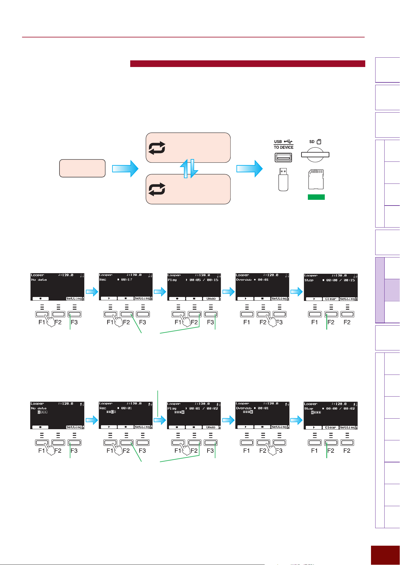
EAD50 EAD20 User Guide
174
Settings in Screens (Parameters)
Modifier
Knobs
LED
Rotary
Faders
[ MIC / TRIG ] [ SCENE ][ CLICK ]
[ RECORDER ]
[ MENU ]
MicTriggerKitEffectRecorder
Looper
SamplingUtilityOutputAux In
USB AudioBluetooth
FileFactory
Reset
Version
[
LIVE SET
]
[RECORDER]-Looper
Successively pressing the [RECORDER] button several times displays the Looper screen. This screen is used to first record a
basic rhythm and then enjoy overlaying other drum rhythms played while repeatedly playing back the first rhythm as a loop. It
is also possible to play a different rhythm and overlay it over an existing rhythm (overdubbing). The recorded data is saved in
internal memory, but can be saved permanently by saving it in external memory.
■ Recording initial loop, overdubbing, and saving data
If Rec Beat Length = Off (steps from recording initial loop to using buttons to playback the loop)
If Rec Beat Length = 4 (steps from recording the initial loop to automatically playing back the loop)
Before recording
Record initial data
([RECORDER] is lit red)
Record overdubbing
([RECORDER] is lit red)
Play loop After recording
[F2][F1]
When 4 beats are finished the
status changes automatically
[F1]
Configure related
settings as necessary.
This functions as an
Undo/Redo button.
This clears (deletes)
the recorded data.
Recording can also be
stopped at this point.
NOTE
The abbreviations “F” (in “F1 – F9”) and
“Alt” refer to “Function” and “Alternative” (for
switching to an alternative), respectively.
They are used to name the buttons for
explanatory convenience. The names are
not printed on the panel.
NOTE
For the Looper function, the key to start
recording loops skillfully is to have Clicks
being played back while pressing the [F1]
button at the optimal timing.
NOTE
The screen transitions shown above are for setting Rec Mode
= Rec
"
Play
"
Dub. The sequence order for playing the loop
(Play) and overdubbing (Overdub) can also be reversed.
Before recording
Record initial data
([RECORDER] is lit red)
Record overdubbing
([RECORDER] is lit red)
Play loop After recording
[F2][F1][F1][F1]
Configure related
settings as necessary.
This functions
as an Undo/
Redo button.
This clears
(deletes) the
recorded data.
Recording can also
be stopped at this
point.
Basic procedure for
Looper functions
Initial recording
Play loop
Check recorded data
Overdubbing recording
Additional layer recorded over
recorded data as loop is played
Transition by
button operations
or automatically
After recording
Button operations
Save data in media
EAD50
Only
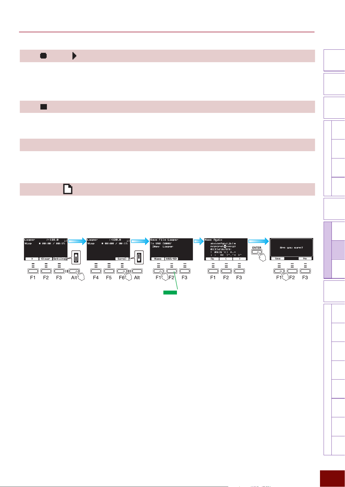
EAD50 EAD20 User Guide
175
Settings in Screens (Parameters)
Modifier
Knobs
LED
Rotary
Faders
[ MIC / TRIG ] [ SCENE ][ CLICK ]
[ RECORDER ]
[ MENU ]
MicTriggerKitEffectRecorder
Looper
SamplingUtilityOutputAux In
USB AudioBluetooth
FileFactory
Reset
Version
[
LIVE SET
]
[F1] / [F1]
If stopped or playing a loop with no data recorded in internal memory, then the [F1] button functions as a start button for
recording. If Looping, that results in recording the sound overlaid over the existing data (overdubbed recording).
During recording (including by overdubbing) and while stopped after recording is finished, the [F1] button functions as a Play
button. In either case, playback switches to playing a loop of all data recorded up to that point.
[F2] / [F2] Clear
During recording, looped playback, or overdubbed recording, the [F2] button functions as a Stop button.
If stopped, the [F2] button functions as a button for deleting data recorded in internal memory.
[F3] Undo / [F3] Redo
During looped playback, this button functions as an Undo/Redo button. If a loop recorded by overdubbing is played
back immediately after recording, then this button can be used to delete (Undo) or restore (Redo) only the data recorded
immediately prior to the current loop.
[F6] Save (saves data from internal memory in external memory)
All data recorded with the Looper are saved in internal memory. To save the data permanently, press the [F6] button to save it
in external memory. The operating steps are the same as for the Recorder screen.
Use the [F2]/[F3] buttons to
move the file name cursor and
then use the [+]/[−] buttons or
knob to select the characters
to be entered. For more
information, refer to Page 66.
After recording Edit file name
Save the file in external
memory
[F6]
[F1]
First Second
Press 2 times.
NOTE
The abbreviations “F” (in “F1 – F9”) and “Alt” refer to “Function” and
“Alternative” (for switching to an alternative), respectively. They are
used to name the buttons for explanatory convenience. The names
are not printed on the panel.
For the
EAD50
model,
select the media (USB
flash drive or SD card) as
necessary.
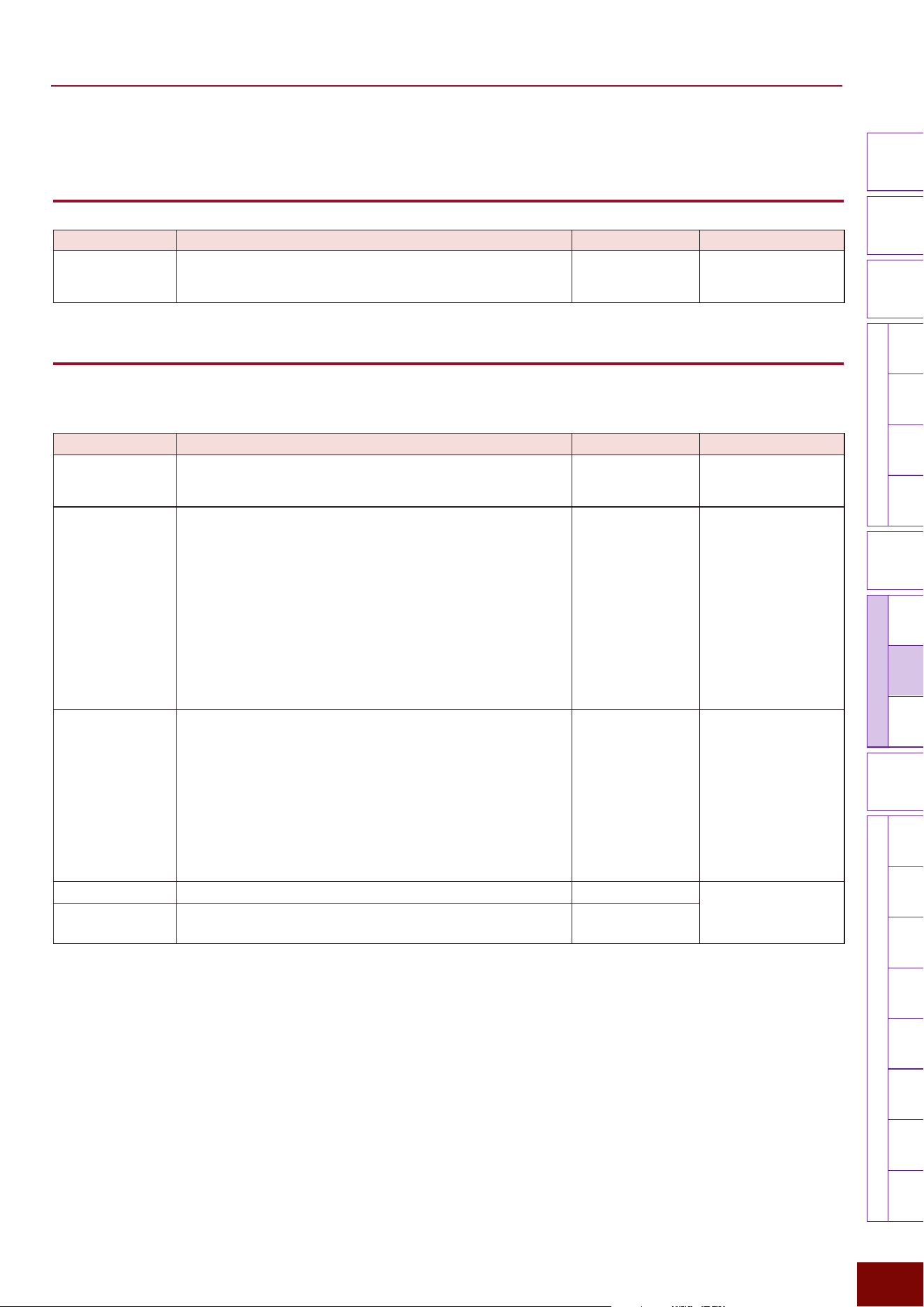
EAD50 EAD20 User Guide
176
Settings in Screens (Parameters)
Modifier
Knobs
LED
Rotary
Faders
[ MIC / TRIG ] [ SCENE ][ CLICK ]
[ RECORDER ]
[ MENU ]
MicTriggerKitEffectRecorder
Looper
SamplingUtilityOutputAux In
USB AudioBluetooth
FileFactory
Reset
Version
[
LIVE SET
]
■ [F3] Setting
[F3] Setting "Looper Vol
Parameter Explanation Setting Default Value
Volume This adjusts the volume level for playing back samples after
they are recorded.
0 – 127 Always set to “100”
for Preset Scenes
(Recorder).
[F3] Setting "Looper Rec
This is used to specify basic settings for recording.
Page 1/2
Parameter Explanation Setting Default Value
Rec Gain This adjusts the gain level for recording from audio sources.
−18 dB, −12 dB,
−6 dB, 0 dB, +6 dB,
+12 dB, +18 dB
Always set to “0dB”
for Preset Scenes
(Recorder).
Rec Mode This selects from two types of Looper recording modes.
Rec
"
Play
"
Dub
After recording a performance, pressing this button switches
to the Play mode and pressing it again switches to the Dub
(overdubbing) mode (for overlaying additional recorded
sounds over the existing recorded phrase).
Rec
"
Dub
"
Play
After recording a performance, pressing this button switches
to the Dub (overdubbing) mode (for overlaying additional
recorded sounds over the existing recorded phrase). Pressing
it again switches to the Play mode.
Rec
"
Play
"
Dub, Rec
"
Dub
"
Play
Always set to “Rec
"
Play
"
Dub” for Preset
Scenes (Recorder).
Rec Beat Length This sets the number of beats for the first recording. Once
you have recorded the number of beats set here at the Click
playback tempo, playback position automatically returns to
the beginning and overdub recording with loop playback of
just recorded phrase starts. This is why you can concentrate
on playing just by following in time with the Click.
NOTE
This setting can be changed during recording, but is actually
applied after the existing recording is deleted ([F2] Clear).
Off, 1 – 32 Always set to “Off”
for Preset Scenes
(Recorder).
Rec Click Sets whether to record Clicks (On) or not (Off).
Off, On Always set to “On”
for Preset Scenes
(Recorder).
Rec Aux In This sets whether to record the audio being input via the [AUX
IN] jack (On) or not (Off).
Off, On
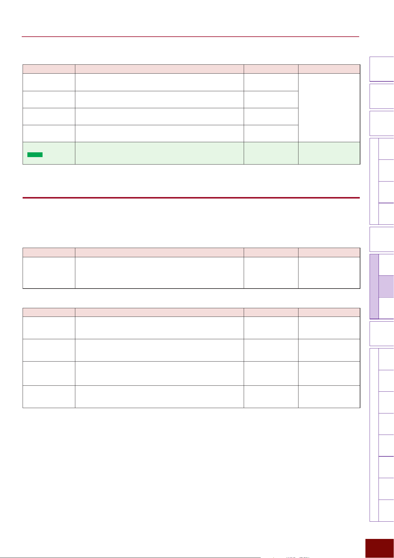
EAD50 EAD20 User Guide
177
Settings in Screens (Parameters)
Modifier
Knobs
LED
Rotary
Faders
[ MIC / TRIG ] [ SCENE ][ CLICK ]
[ RECORDER ]
[ MENU ]
MicTriggerKitEffectRecorder
Looper
SamplingUtilityOutputAux In
USB AudioBluetooth
FileFactory
Reset
Version
[
LIVE SET
]
Page 2/2
Parameter Explanation Setting Default Value
Rec USB Audio
In1/2
This sets whether to record audio channels 1/2 being input via
the [USB TO HOST] terminal (On) or not (Off).
Off, On Always set to “On”
for Preset Scenes
(Recorder).
Rec USB Audio
In3/4
This sets whether to record audio channels 3/4 being input via
the [USB TO HOST] terminal (On) or not (Off).
Off, On
Rec USB Audio
In5/6
This sets whether to record audio channels 5/6 being input via
the [USB TO HOST] terminal (On) or not (Off).
Off, On
Rec USB Audio
In7/8
This sets whether to record audio channels 7/8 being input via
the [USB TO HOST] terminal (On) or not (Off).
Off, On
Rec Bluetooth
(
EAD50
only)
This sets whether to record the audio being input via Bluetooth
(On) or not (Off).
Off, On Always set to “On”
for Preset Scenes
(Recorder).
[F3] Setting "Looper EQ
Used to specify EQ settings for audio currently being played back using this function.
NOTE
For more information about equalizers (EQ), refer to the diagrams on Page 32.
Page 1/6
Parameter Explanation Setting Default Value
On/Off
This sets whether to apply EQ to audio being played back
using this function (On) or not (Off). The “Off” setting has an
equivalent effect as setting Gain = 0 and HPF Freq = Thru for
each frequency band.
Off, On Always set to “Off”
for Preset Scenes
(Recorder).
Page 2/6
Parameter Explanation Setting Default Value
Low Freq This sets the midpoint of the EQ low frequency band for audio
currently being played back using this function.
32Hz – 2.0kHz Always set to “125Hz”
for Preset Scenes
(Recorder).
Low Gain
Used to boost or cut signals near the frequency specified for
Low Freq.
−12dB – 0dB –
+12dB
Always set to “0dB”
for Preset Scenes
(Recorder).
Low Q This sets the Q factor (frequency characteristics) for the EQ
low frequency band. If Low Shape is set to LowShelving, then
the Low Q value will have no effect.
0.1 – 12.0 Always set to “0.9”
for Preset Scenes
(Recorder).
Low Shape This selects the shape of frequency characteristics for the EQ
low frequency band.
LowShelving,
PeakDip
Always set to
“LowShelving” for Preset
Scenes (Recorder).
EAD50 EAD20 User Guide
178
Settings in Screens (Parameters)
Modifier
Knobs
LED
Rotary
Faders
[ MIC / TRIG ] [ SCENE ][ CLICK ]
[ RECORDER ]
[ MENU ]
MicTriggerKitEffectRecorder
Looper
SamplingUtilityOutputAux In
USB AudioBluetooth
FileFactory
Reset
Version
[
LIVE SET
]
Page 3/6
Parameter Explanation Setting Default Value
MidLow Freq
This sets the midpoint of the EQ low-to-mid frequency band for
audio currently being played back using this function.
100Hz – 10.0kHz Always set to “500Hz”
for Preset Scenes
(Recorder).
MidLow Gain Used to boost or cut signals near the frequency specified for
MidLow Freq.
−12dB – 0dB –
+12dB
Always set to “0dB”
for Preset Scenes
(Recorder).
MidLow Q This sets the Q factor (frequency characteristics) for the EQ
low-to-mid frequency band.
0.1 – 12.0 Always set to “0.7”
for Preset Scenes
(Recorder).
Page 4/6
Parameter Explanation Setting Default Value
MidHigh Freq
This sets the midpoint of the EQ low-to-high frequency band for
audio currently being played back using this function.
100Hz – 10.0kHz Always set to “4.0kHz”
for Preset Scenes
(Recorder).
MidHigh Gain Used to boost or cut signals near the frequency specified for
MidHigh Freq.
−12dB – 0dB –
+12dB
Always set to “0dB”
for Preset Scenes
(Recorder).
MidHigh Q This sets the Q factor (frequency characteristics) for the EQ
mid-to-high frequency band.
0.1 – 12.0 Always set to “0.9”
for Preset Scenes
(Recorder).
Page 5/6
Parameter Explanation Setting Default Value
High Freq
This sets the midpoint of the EQ high frequency band for audio
currently being played back using this function.
500Hz – 16.0kHz Always set to “9.0kHz”
for Preset Scenes
(Recorder).
High Gain
Used to boost or cut signals near the frequency specified for
High Freq.
−12dB – 0dB –
+12dB
Always set to “0dB”
for Preset Scenes
(Recorder).
High Q This sets the Q factor (frequency characteristics) for the EQ
high frequency band. If High Shape is set to HighShelving,
then the High Q value has no effect.
0.1 – 12.0 Always set to “0.9”
for Preset Scenes
(Recorder).
High Shape This selects the shape of frequency characteristics for the EQ
high frequency band. If LPF is selected, the entire equalizer
changes to functioning as a low-pass filter.
HighShelving,
PeakDip, LPF
Always set to
“HighShelving” for Preset
Scenes (Recorder).
Page 6/6
Parameter Explanation Setting Default Value
HPF Freq
Separately from EQ settings, a high-pass filter (HPF) can
also be applied to audio played back using this function. The
filter cuts sounds with frequencies lower than the specified
frequency. If “Thru” is specified, the HPF is not applied.
Thru, 56Hz –
2.0kHz
Always set to “Thru”
for Preset Scenes
(Recorder).
HPF Q This sets the Q factor (frequency characteristics) for the high-
pass filter.
0.1 – 12.0 Always set to “0.7”
for Preset Scenes
(Recorder).
EAD50 EAD20 User Guide
179
Settings in Screens (Parameters)
Modifier
Knobs
LED
Rotary
Faders
[ MIC / TRIG ] [ SCENE ][ CLICK ]
[ RECORDER ]
[ MENU ]
MicTriggerKitEffectRecorder
Looper
SamplingUtilityOutputAux In
USB AudioBluetooth
FileFactory
Reset
Version
[
LIVE SET
]
[F3] Setting "Looper Out
Used to specify settings for external output of audio currently being played back using this function.
Page 1/2
Parameter Explanation Setting Default Value
Main Out This sets whether to output audio currently being played back
using this function from [OUTPUT] jacks (On) or not (Off).
Off, On Always set to “On”
for Preset Scenes
(Recorder).
Phones Out This sets whether to output audio currently being played back
using this function from [PHONES] jacks (On) or not (Off).
Off, On
USB Audio Out
1/2
This sets whether to output audio currently being played back
using this function from the [USB TO HOST] terminal (On) or
not (Off).
Off, On
Page 2/2
Parameter Explanation Setting Default Value
IndivOut
(
EAD50
only)
This specifies which channel ([INDIVIDUAL OUTPUT] jacks)
to use for external output of audio currently being played
back using this function.
Off, L1+R2, L3+R4,
L5+R6, L7+R8,
L(1+2), R(1+2),
L(3+4), R(3+4),
L(5+6), R(5+6),
L(7+8), R(7+8),
L1, R2, L3, R4, L5,
R6, L7, R8, (L+R)1,
(L+R)2, (L+R)3,
(L+R)4, (L+R)5,
(L+R)6, (L+R)7,
(L+R)8
For a description of
each setting value,
refer to the table at the
bottom of Page 116.
Always set to “Off”
for Preset Scenes
(Recorder).
IndivOut Vol
(
EAD50
only)
Sets the volume level for output from [INDIVIDUAL OUTPUT]
jacks of audio played back using this function. If “Variable” is
specified, the volume is linked to [AUDIO] slider operations.
Variable, 1 – 127 Always set to “Variable”
for Preset Scenes
(Recorder).
USB AudOut
(
EAD20
only)
This sets whether to use the left (L) or right (R) channel for left
(L) and right (R) channels for external output of playback via a
USB cable using this function.
Off, L3+R4, L5+R6,
L7+R8, L9+R10, L3,
R4, L5, R6, L7, R8,
L9, R10, (L+R)3,
(L+R)4, (L+R)5,
(L+R)6, (L+R)7,
(L+R)8, (L+R)9,
(L+R)10
* For a description of
respective setting
values, refer to the
table at the bottom of
Page 117.
Always set to “Off”
for Preset Scenes
(Recorder).
USB AudOut Vol
(
EAD20
only)
This adjusts the volume for external output of playback using this
function via a USB cable. If “Variable” is specified, the volume is
linked to [MASTER] knob operations.
Variable, 1 – 127 Always set to “Variable”
for Preset Scenes
(Recorder).
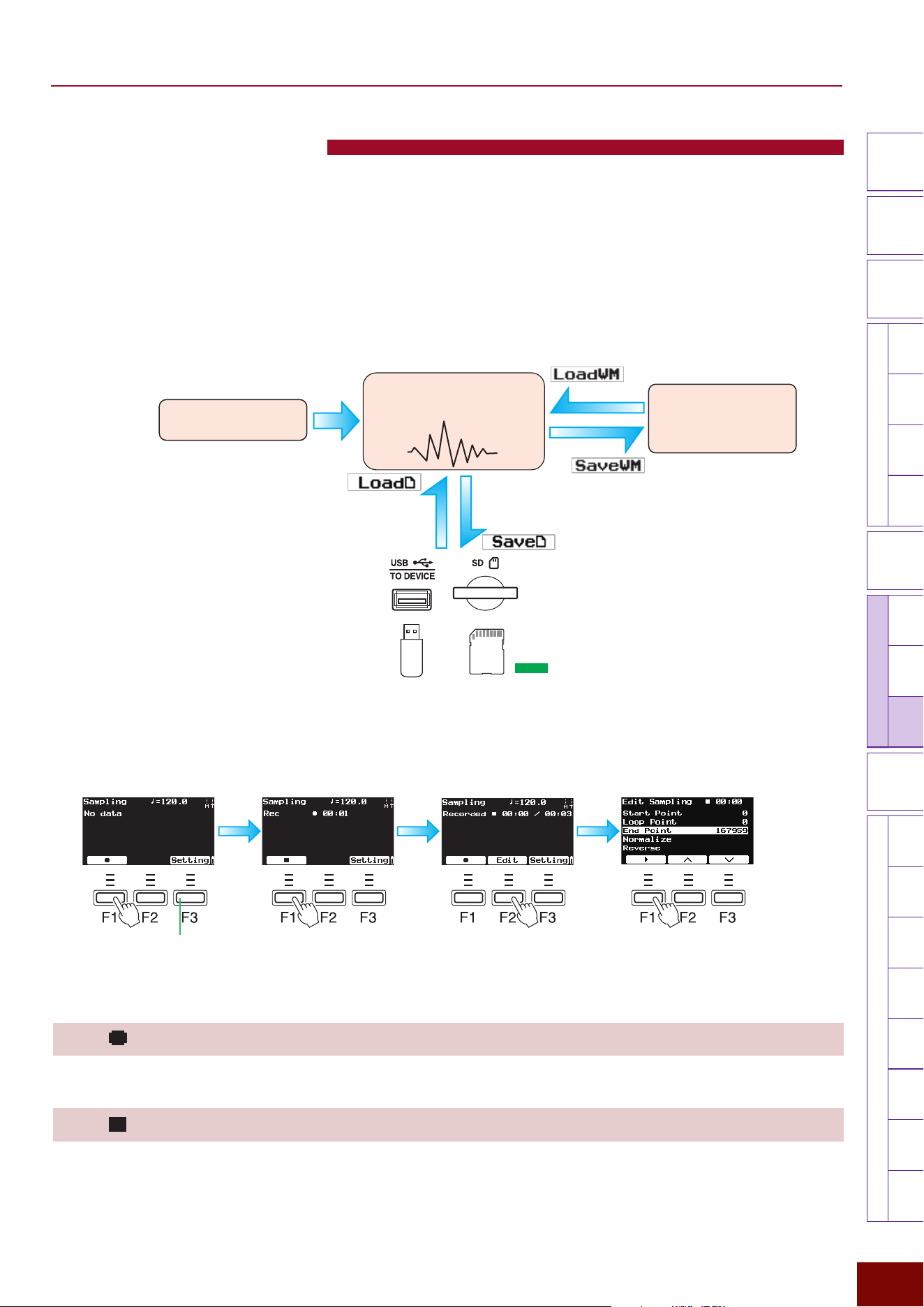
EAD50 EAD20 User Guide
180
Settings in Screens (Parameters)
Modifier
Knobs
LED
Rotary
Faders
[ MIC / TRIG ] [ SCENE ][ CLICK ]
[ RECORDER ]
[ MENU ]
MicTriggerKitEffectRecorderLooper
Sampling
UtilityOutputAux In
USB AudioBluetooth
FileFactory
Reset
Version
[
LIVE SET
]
[RECORDER]-Sampling
Successively pressing the [RECORDER] button several times displays Sampling screen. Sampling is the function for recording
instrumental, vocal, or other audio sounds as digital data in internal memory inside this product and then refining that data as
samples by editing the waveforms the data contains. Instead of users recording (Sampling) themselves, samples can also be
imported from WAV files saved in media. Samples refined by editing can then be used in performances by assigning them to
User Voices.
NOTE
The basic flow of the Sampling is to edit the waveforms of recorded data (sample) in internal memory and then save the edited sample to
wave memory. For more information about the configuration of corresponding memory, refer to Page 33.
Basic procedure for Sampling
functions
Record sample
(Sampling)
Assign sample to User
Voice
Edit waveforms
Refine as sample
Saves edited data in media
as a WAV file
WAV file loaded
from media
Internal Memory
Wave Memory
Media (Internal Memory)
(
EAD50
only)
■ Recording/Editing
Configure related
settings as necessary.
Before starting recording Edit
NOTE
The “F” in “F1 – F3” refers to “Function” and is used to name the buttons
for explanatory convenience. The names are not printed on the panel.
During recording After recording
[F1]
At the point when the Sampling screen is entered (before starting recording), this button functions as a Record button.
[F1]
During recording, this button functions as a Stop button.
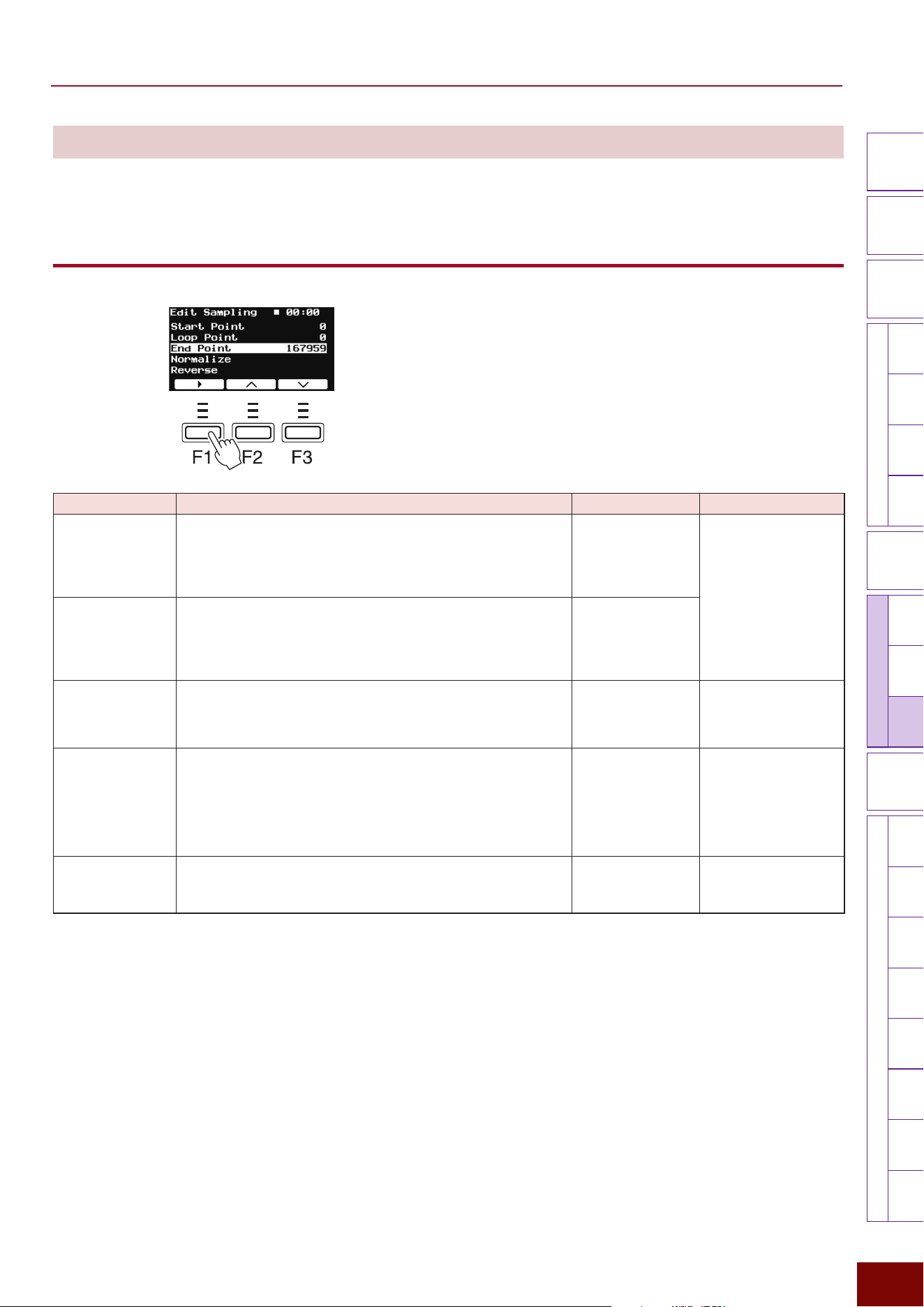
EAD50 EAD20 User Guide
181
Settings in Screens (Parameters)
Modifier
Knobs
LED
Rotary
Faders
[ MIC / TRIG ] [ SCENE ][ CLICK ]
[ RECORDER ]
[ MENU ]
MicTriggerKitEffectRecorderLooper
Sampling
UtilityOutputAux In
USB AudioBluetooth
FileFactory
Reset
Version
[
LIVE SET
]
[F2] Edit
After recording is finished, this button is displayed only if there is a sample (recorded data) in internal memory. It is used to edit
waveforms contained in samples.
[F2] Edit "[F1] Play / [F1] Stop
This starts or stops playback of the sample currently being edited.
Parameter Explanation Setting Default Value
Start Point Specifies the position for starting sample playback. Data
before this position is not played back.
Value that indicates
a position between
zero and immediately
before the end of the
sample.
Always set to “0”
for Preset Scenes
(Recorder).
Loop Point Specifies the position for starting Looping during sample
playback.
Value that indicates
a position between
zero and immediately
before the end of the
sample.
End Point Specifies the position for ending sample playback. Data after
this position is not played back.
Value that indicates
a position between
1 and the end of the
sample.
Value that indicates the
sample end position.
Normalize This converts data so it is amplified to maximum sample
volume. It is used to amplify volume to an appropriate level
for samples recorded with a low volume level. With the
amplification rate (Ratio) specified in the screen displayed
by pressing the [ENTER] button, the Normalize function is
executed by pressing the [ENTER] button again.
— —
Reverse This converts data to a state after it has been played in the
opposite direction. The function is executed by pressing
[ENTER].
— —
EAD50 EAD20 User Guide
182
Settings in Screens (Parameters)
Modifier
Knobs
LED
Rotary
Faders
[ MIC / TRIG ] [ SCENE ][ CLICK ]
[ RECORDER ]
[ MENU ]
MicTriggerKitEffectRecorderLooper
Sampling
UtilityOutputAux In
USB AudioBluetooth
FileFactory
Reset
Version
[
LIVE SET
]
[F3] Setting
This is used to specify Sampling parameter settings before recording.
[F3] Setting"Sampling Vol
Parameter Explanation Setting Default Value
Volume This adjusts the volume level for playing back samples after
they are recorded.
0 – 127 Always set to “100”
for Preset Scenes
(Recorder).
[F3] Setting "Sampling Rec
Page 1/2
Parameter Explanation Setting Default Value
Rec Gain This adjusts the gain level for recording from audio sources.
−18dB, −12dB,
−6dB, 0dB, +6dB,
+12dB, +18dB
Always set to “0dB”
for Preset Scenes
(Recorder).
Rec Click Sets whether to record Clicks (On) or not (Off).
Off, On Always set to “On”
for Preset Scenes
(Recorder).
Rec Aux In This sets whether to record the audio being input via the [AUX
IN] jack (On) or not (Off).
Off, On
Rec USB Audio
In1/2
This sets whether to record audio channels 1/2 being input via
the [USB TO HOST] terminal (On) or not (Off).
Off, On
Rec USB Audio
In3/4
This sets whether to record audio channels 3/4 being input via
the [USB TO HOST] terminal (On) or not (Off).
Off, On
Page 2/2
Parameter Explanation Setting Default Value
Rec USB Audio
In5/6
This sets whether to record audio channels 5/6 being input via
the [USB TO HOST] terminal (On) or not (Off).
Off, On Always set to “On”
for Preset Scenes
(Recorder).
Rec USB Audio
In7/8
This sets whether to record audio channels 7/8 being input via
the [USB TO HOST] terminal (On) or not (Off).
Off, On
Rec Bluetooth
(
EAD50
only)
This sets whether to record the audio being input via Bluetooth
(On) or not (Off).
Off, On Always set to “On”
for Preset Scenes
(Recorder).
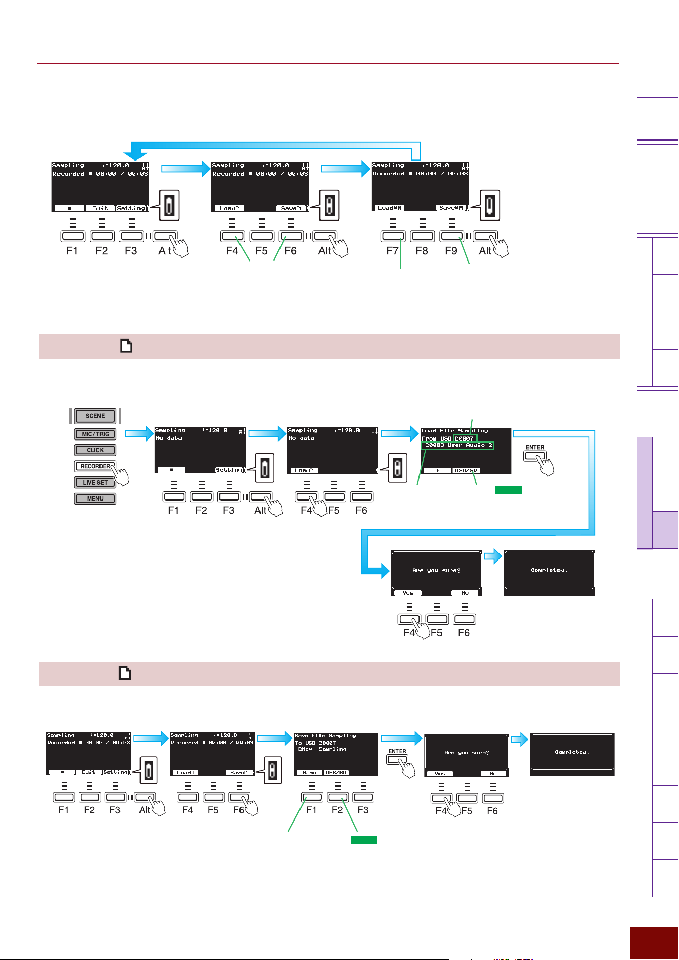
EAD50 EAD20 User Guide
183
Settings in Screens (Parameters)
Modifier
Knobs
LED
Rotary
Faders
[ MIC / TRIG ] [ SCENE ][ CLICK ]
[ RECORDER ]
[ MENU ]
MicTriggerKitEffectRecorderLooper
Sampling
UtilityOutputAux In
USB AudioBluetooth
FileFactory
Reset
Version
[
LIVE SET
]
■ Saving/loading samples
[F4] Load
This is used to specify Sampling parameter settings before recording.
It imports audio files (WAV) in external memory into internal memory (internal memory area for editing samples).
SecondFirst
Press
multiple
times.
Select the file using
[+]/[−] buttons or knob
For the
EAD50
model,
select the media (USB
flash drive or SD card) as
necessary.
Number of WAV files saved in storage media
[F6] Save
This saves created samples as audio files (WAV) in external memory.
This names files to be
saved. For more details,
refer to Page 66.
For the
EAD50
model,
select the media (USB
flash drive or SD card) as
necessary.
Second
First
After recording
Only displayed if Sampling data is
stored in internal memory.
Only displayed if a sample is
assigned to one of the Voice banks.
Displayed only if an external
memory device is connected.
NOTE
The abbreviations “F” (in “F1 –
F9”) and “Alt” refer to “Function”
and “Alternative” (for switching to
an alternative), respectively. They
are used to name the buttons for
explanatory convenience. The
names are not printed on the
panel.
SecondFirst Third
After recording
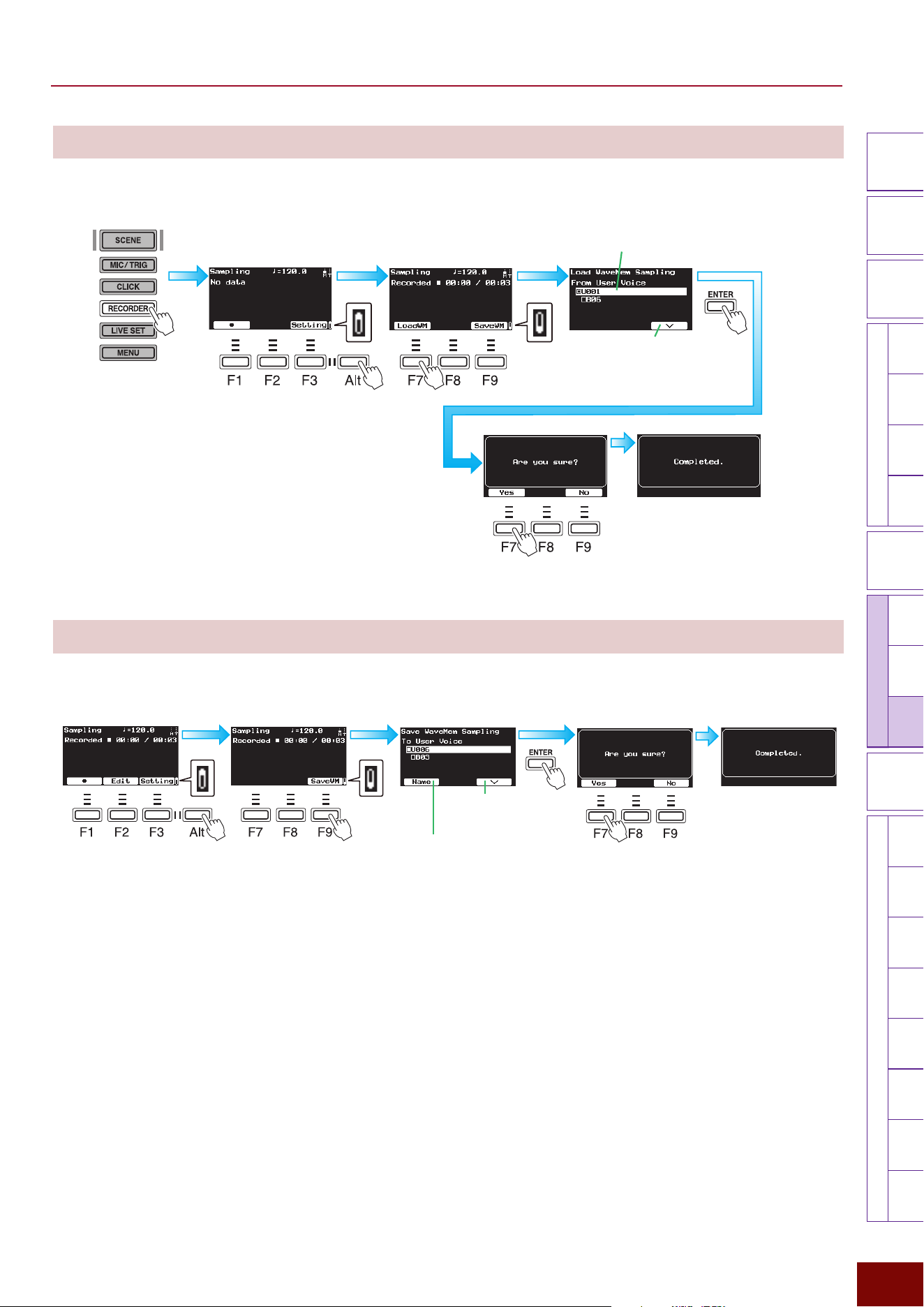
EAD50 EAD20 User Guide
184
Settings in Screens (Parameters)
Modifier
Knobs
LED
Rotary
Faders
[ MIC / TRIG ] [ SCENE ][ CLICK ]
[ RECORDER ]
[ MENU ]
MicTriggerKitEffectRecorderLooper
Sampling
UtilityOutputAux In
USB AudioBluetooth
FileFactory
Reset
Version
[
LIVE SET
]
[F7] LoadWM
This loads samples assigned to any User Voice/bank in wave memory into internal memory.
[F9] SaveWM
Saves created samples in any User Voice or bank.
Name the User Voice and bank where
the wave memory is to be saved. For
naming instructions, refer to Page 66.
Moves the cursor
between the User Voice
and bank.
Third
First
Press 2
times.
After recording
ThirdFirst
Press
multiple
times.
Moves the cursor between the
User Voice and bank.
Use the [+]/[−] buttons or knob to select the User
Voice number (U001 or higher) and bank number
(B01 – B10) for the User Voice to be loaded.
Press 2 times.
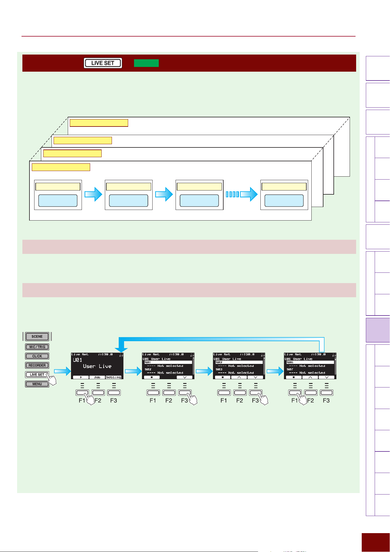
EAD50 EAD20 User Guide
185
Settings in Screens (Parameters)
Modifier
Knobs
LED
Rotary
Faders
[ MIC / TRIG ] [ SCENE ][ CLICK ][ RECORDER ]
[ MENU ]
MicTriggerKitEffectRecorderLooperSamplingUtilityOutputAux In
USB AudioBluetooth
FileFactory
Reset
Version
[
LIVE SET
]
[LIVE SET] (
EAD50
only)
“Live Set” is the function that allows you to program the desired order of “Scenes” and then call them up in the programmed
order. For your live performances, it can be used to program a sequence of Scenes including the Kits which you want to use.
For your rhythm practice, it can be used to program a sequence of Scenes including audio files in order of difficulty.
This product can save up to 50 user-specified Live Sets, which can be freely selected for use in performances or practice.
[−] [+] Live Set
Setting range: U01 to U50 Default value: U01
[F1] Live Set Start
This starts a live performance of a selected Live Set. During the live performance, the Scene switches as the performance
advances to the next step.
NOTE
The abbreviations “F” (in “F1 – F3”) and “Alt” refer to “Function” and “Alternative” (for switching to
an alternative), respectively. They are used to name the buttons for explanatory convenience. The
names are not printed on the panel.
1.
Use [+]/[−] buttons or
the knob to select the
Live Set.
During the live performance
(current step is indicated in top row)
2.
Start the Live Set. 4. Stop the Live Set.3. Use the [F3]/[F2] buttons or [+]/[−] buttons/
knob to move forward or back one step.
Step 01 (S01) Step 02 (S02) Step 03 (S03) Step 50 (S50)
Live Set 01 (U01)
Live Set 02 (U02)
Live Set 03 (U03)
Live Set 50 (U50)
Scene xxScene xxScene xxScene xx
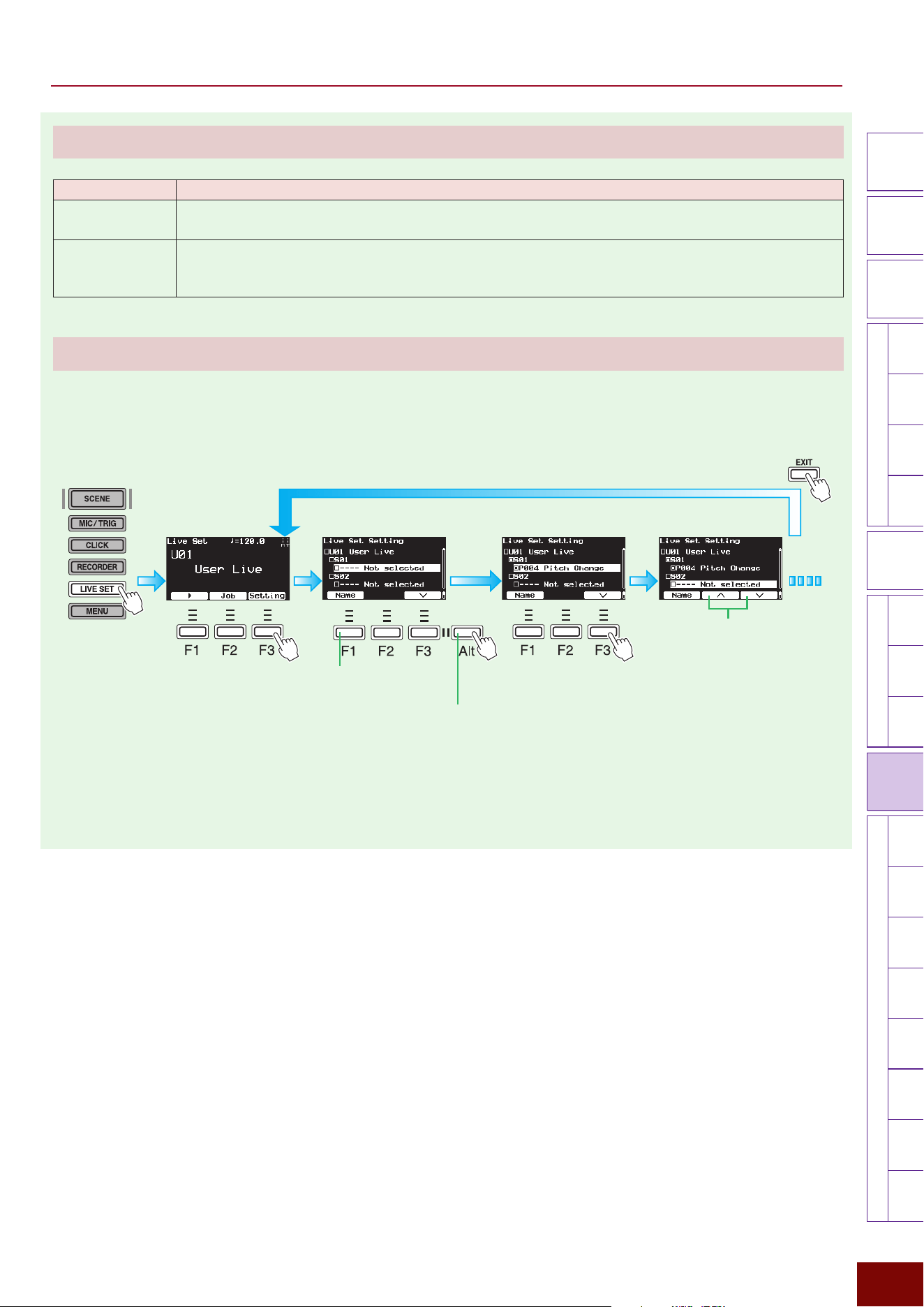
EAD50 EAD20 User Guide
186
Settings in Screens (Parameters)
Modifier
Knobs
LED
Rotary
Faders
[ MIC / TRIG ] [ SCENE ][ CLICK ][ RECORDER ]
[ MENU ]
MicTriggerKitEffectRecorderLooperSamplingUtilityOutputAux In
USB AudioBluetooth
FileFactory
Reset
Version
[
LIVE SET
]
[F2] Job
Parameter Explanation
Sort This changes the step order of Live Sets. Press the [ENTER] button before performing Sort operations.
For more information, refer to “Basic Operations” (Page 67).
Clear
This clears respective Live Sets from memory.
After pressing the [ENTER] button, use the [+]/[−] buttons or knob to select a Live Set and then press the
[ENTER] button again to clear the Live Set.
[F3] Setting
This creates Live Sets by registering Scene numbers for each step.
Each step can be named in the screen displayed by pressing the [F1] Name button.
1. Use the [+]/[−] buttons
or knob to select the
Live Set.
2.
Display the Edit screen.
4. Advance to the
next step (S02).
3.
Use the [+]/[−] buttons or knob to select the Scene for S01 (step 01).
Live Sets can be named by
loading the Edit Name screen.
For the naming procedure,
refer to Page 66.
5. Similarly, use the [+]/[−] buttons
or knob to select the Scene and
then press the [F3] button to
advance to the next step.
Pressing the [Alt] button
toggles the function for
the [F1] button between
“Name” and “Sort.”
6. After editing all the necessary steps,
press the [EXIT] button to display the
previous screen again.
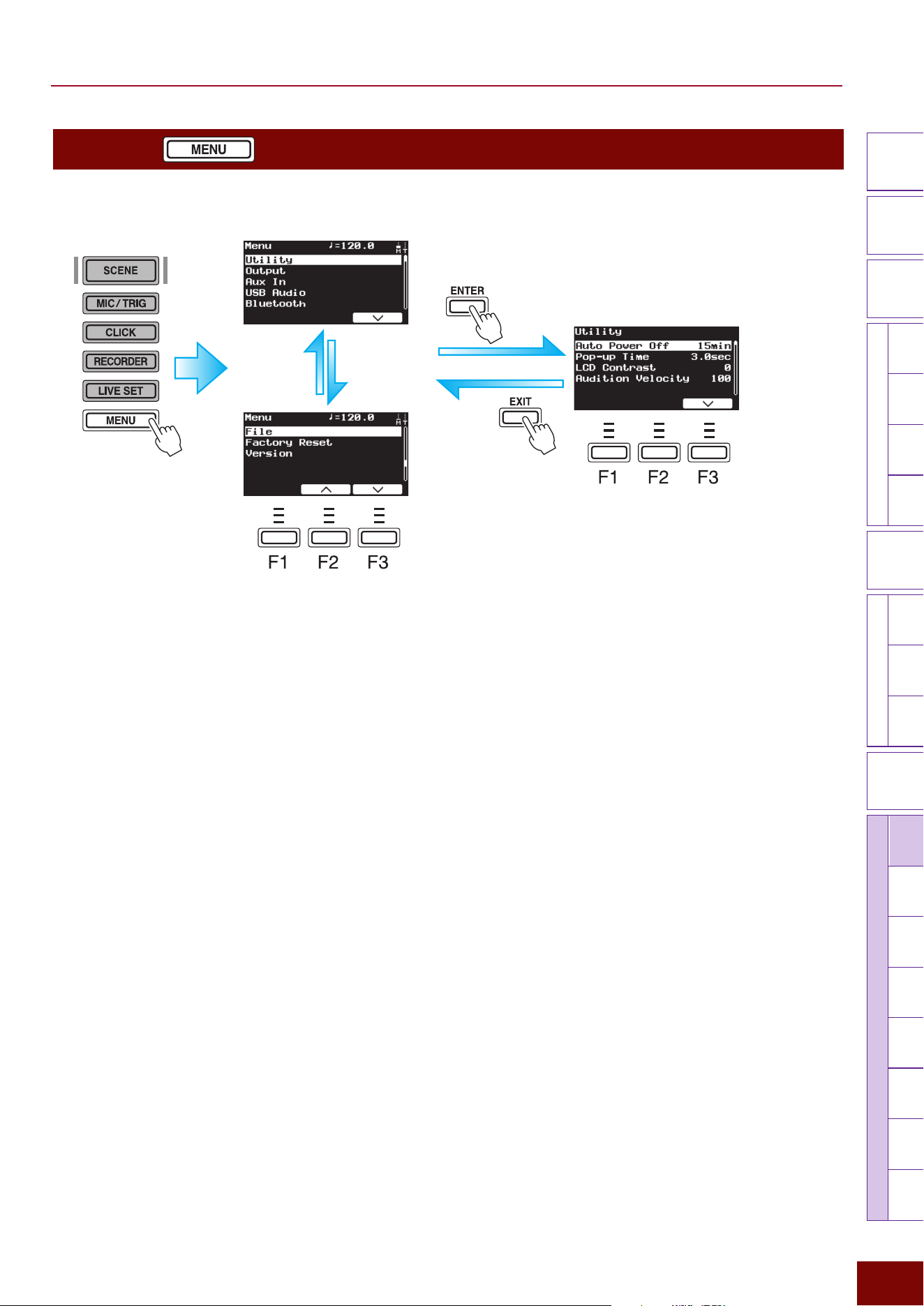
EAD50 EAD20 User Guide
187
Settings in Screens (Parameters)
Modifier
Knobs
LED
Rotary
Faders
[ MIC / TRIG ] [ SCENE ][ CLICK ][ RECORDER ]
[ MENU ]
MicTriggerKitEffectRecorderLooperSampling
Utility
OutputAux In
USB AudioBluetooth
FileFactory
Reset
Version
[
LIVE SET
]
[MENU]
Mainly used for global settings that affect this product entirely.
First page
Second page
Press [F3] to move
the cursor down
Press [F2]
to move the
cursor up
This shows an example of setting
[MENU]
"
Utility
"
Auto Power Off.
NOTE
The “F” in “F1 – F3” refers to “Function” and is used to name the buttons
for explanatory convenience. The names are not printed on the panel.
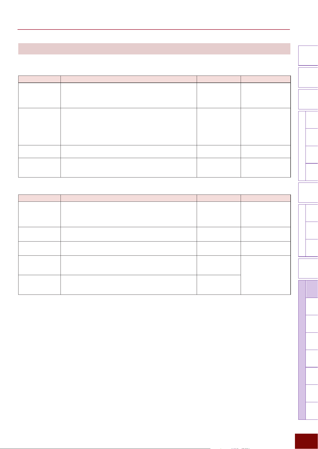
EAD50 EAD20 User Guide
188
Settings in Screens (Parameters)
Modifier
Knobs
LED
Rotary
Faders
[ MIC / TRIG ] [ SCENE ][ CLICK ][ RECORDER ]
[ MENU ]
MicTriggerKitEffectRecorderLooperSampling
Utility
OutputAux In
USB AudioBluetooth
FileFactory
Reset
Version
[
LIVE SET
]
Utility
Page 1/4
Parameter Explanation Setting Default Value
Auto Power Off To reduce power consumption, this product automatically
shuts off the power if no operations have been performed for
a specified period. This setting specifies how long it waits
before shutting off the power.
Off, 5 min, 10 min,
15min, 30 min,
60min, 120min
Always set to “15 min” for
Preset Scenes (Utility).
Pop-up Time
This sets how long pop-up windows remain displayed before
automatically disappearing, such as whenever a modifier
knob in the upper left of the panel or an LED rotary fader in the
bottom center area of the panel is operated.
If “Hold” is specified, pop-up windows will not disappear until
another button is operated.
1.0 sec, 1.5 sec,
2.0sec, 2.5 sec,
3.0sec, 3.5 sec,
4.0sec, 4.5 sec,
5.0sec, 5.5 sec,
6.0sec, Hold
Always set to “3.0sec”
for Preset Scenes
(Utility).
LCD Contrast This adjusts the screen contrast level.
−50 – 0 – +50 Always set to “0” for
Preset Scenes (Utility).
Audition Velocity This sets the velocity of the preview sound (audition)
produced by pressing the [F3] button in the Trigger Input
Select screen (Page 63).
Off, 1 – 127 Always set to “100” for
Preset Scenes (Utility).
Page 2/4
Parameter Explanation Setting Default Value
MIDI Local Control
This sets whether to produce sound from the internal tone
generator in this product when a pad is hit (On) or not (Off). To
play sound only from the tone generator in the connected MIDI
device, set this to “Off.”
Off, On Always set to “On” for
Preset Scenes (Utility).
MIDI Global
Channel
This sets the channel to use for integrating MIDI messages in
the same channel.
1 – 16 Always set to “10” for
Preset Scenes (Utility).
MIDI Global Port This sets the MIDI port associated with the channel specified
by the MIDI Global Channel setting.
1 – 2 Always set to “1” for
Preset Scenes (Utility).
MIDI PC Tx This is an abbreviation of “MIDI Program Change
Transmission.” It sets whether or not to transmit a program
change whenever a Scene is changed.
Off, On Always set to “On” for
Preset Scenes (Utility).
MIDI PC Rx This is an abbreviation of “MIDI Program Change Reception.”
It specifies whether to implement program change instructions
received by this product (On) or ignore them (Off).
Off, On
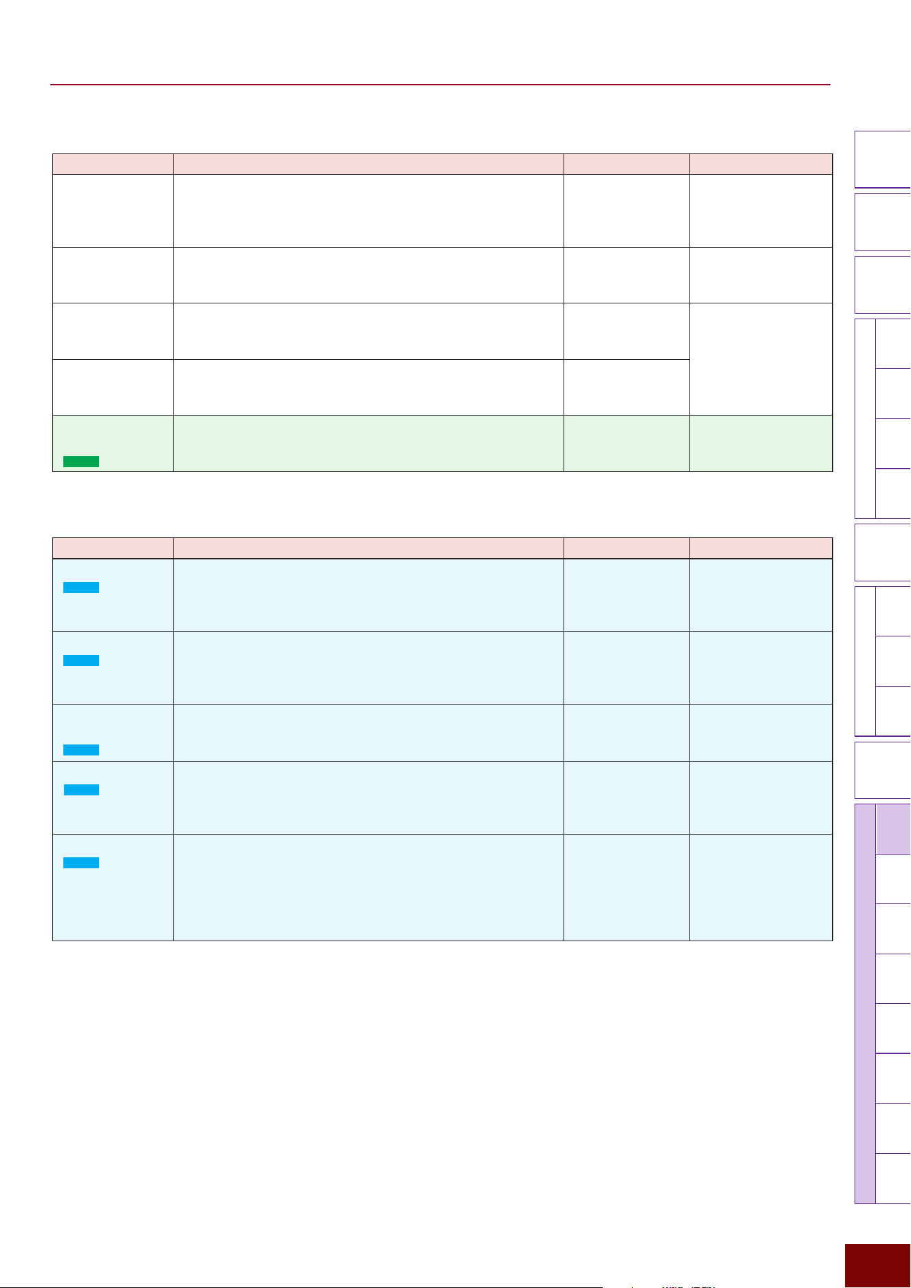
EAD50 EAD20 User Guide
189
Settings in Screens (Parameters)
Modifier
Knobs
LED
Rotary
Faders
[ MIC / TRIG ] [ SCENE ][ CLICK ][ RECORDER ]
[ MENU ]
MicTriggerKitEffectRecorderLooperSampling
Utility
OutputAux In
USB AudioBluetooth
FileFactory
Reset
Version
[
LIVE SET
]
Page 3/4
Parameter Explanation Setting Default Value
MIDI Clock Tx This is an abbreviation of “MIDI Clock Transmission.” It sets
whether or not to transmit MIDI clock data. If set to “On,” it
continuously outputs F8 in accordance with the current tempo
setting.
Off, On Always set to “On” for
Preset Scenes (Utility).
MIDI Clock Rx This is an abbreviation of “MIDI Clock Reception.” This sets
whether the MIDI clock received from the external devices is
implemented (On) or ignored (Off).
Off, On Always set to “Off” for
Preset Scenes (Utility).
MIDI Start/Stop Tx This is an abbreviation of “MIDI Start/Stop Transmission.” This
sets whether the MIDI real time message (FA/FC) is sent (On)
or not (Off) when the Click playback starts or stops.
Off, On Always set to “On” for
Preset Scenes (Utility).
MIDI Start/Stop
Rx
This is an abbreviation of “MIDI Start/Stop Reception.” This
sets whether (On) or not (Off) the start/stop of Click playback
is affected by MIDI real time messages (FA/FC).
Off, On
USB MIDI Thru
MIDI
(
EAD50
only)
This sets whether to send MIDI Port 1 messages received
via the [USB TO HOST] terminal directly from the [MIDI OUT]
terminal (On) or not (Off).
Off, On Always set to “Off” for
Preset Scenes (Utility).
Page 4/4
Parameter Explanation Setting Default Value
Main Volume
(
EAD20
only)
This sets the gain level for audio output from [OUTPUT] jacks.
If “Variable” is specified, the volume is linked to [MASTER]
knob operations. A setting other than “Variable” will disable
using the [MASTER] knob to adjust the volume.
Variable, 1 – 127 Always set to “Variable”
for Preset Scenes
(Utility).
Phones Volume
(
EAD20
only)
Sets the headphones volume level. If “Variable” is specified,
the volume is linked to [MASTER] knob operations. A setting
other than “Variable” will disable using the [MASTER] knob to
adjust the volume.
Variable, 1 – 127 Always set to “Variable”
for Preset Scenes
(Utility).
Mic/Trigger
Volume
(
EAD20
only)
Sets the volume for mic input and Trigger Input sounds.
0 – 127 Always set to “127” for
Preset Scenes (Utility).
Click Volume
(
EAD20
only)
Sets the volume for playing clicks. If “Variable” is specified,
the volume is linked to [AUDIO/CLICK] knob operations. A
setting other than “Variable” will disable using the [AUDIO/
CLICK] knob to adjust the volume.
Variable, 1 – 127 Always set to “Variable”
for Preset Scenes
(Utility).
Audio Volume
(
EAD20
only)
Sets audio playback using the Recorder function and the
volume level of audio inputs to the [AUX IN] jack and [USB
TO HOST] terminal. If “Variable” is specified, the volume is
linked to [AUDIO/CLICK] knob operations. A setting other
than “Variable” will disable using the [AUDIO/CLICK] knob to
adjust the volume.
Variable, 1 – 127 Always set to “Variable”
for Preset Scenes
(Utility).
EAD50 EAD20 User Guide
190
Settings in Screens (Parameters)
Modifier
Knobs
LED
Rotary
Faders
[ MIC / TRIG ] [ SCENE ][ CLICK ][ RECORDER ]
[ MENU ]
MicTriggerKitEffectRecorderLooperSamplingUtility
Output
Aux In
USB AudioBluetooth
FileFactory
Reset
Version
[
LIVE SET
]
Output
Output "Output Gain
This sets the gain level for audio output via respective jacks.
Page 1/2
Parameter Explanation Setting Default Value
Main Out This sets the gain level for audio output from the [OUTPUT]
jacks (L + R).
−18 dB, −12 dB,
−6 dB, 0 dB, +6 dB,
+12 dB, +18 dB
Always set to “0dB” for
Preset Scenes (Output).
Phones Out
This sets the gain level for audio output from the [PHONES]
jack.
−18 dB, −12 dB,
−6 dB, 0 dB, +6 dB,
+12 dB, +18 dB
Page 2/2 (
EAD50
only)
Parameter Explanation Setting Default Value
IndivOut1/2 Sets the gain level for audio output from [INDIVIDUAL
OUTPUT] jacks 1 and 2.
−18 dB, −12 dB,
−6 dB, 0 dB, +6 dB,
+12 dB, +18 dB
Always set to “0dB” for
Preset Scenes (Output).
IndivOut3/4 Sets the gain level for audio output from [INDIVIDUAL
OUTPUT] jacks 3 and 4.
−18 dB, −12 dB,
−6 dB, 0 dB, +6 dB,
+12 dB, +18 dB
IndivOut5/6 Sets the gain level for audio output from [INDIVIDUAL
OUTPUT] jacks 5 and 6.
−18 dB, −12 dB,
−6 dB, 0 dB, +6 dB,
+12 dB, +18 dB
IndivOut7/8 Sets the gain level for audio output from [INDIVIDUAL
OUTPUT] jacks 7 and 8.
−18 dB, −12 dB,
−6 dB, 0 dB, +6 dB,
+12 dB, +18 dB
Output "Phones EQ
This adjusts the EQ applied to headphone sounds.
NOTE
For more information about equalizers (EQ), refer to the diagrams on Page 32.
Page 1/5
Parameter Explanation Setting Default Value
On/Off
Specifies whether or not to apply EQ to headphone sounds.
On, Off Always set to “Off” for
Preset Scenes (Output).
Type This selects the EQ type applied to headphone sounds.
Refer to EQ type list Always set to “Thru” for
Preset Scenes (Output).
EAD50 EAD20 User Guide
191
Settings in Screens (Parameters)
Modifier
Knobs
LED
Rotary
Faders
[ MIC / TRIG ] [ SCENE ][ CLICK ][ RECORDER ]
[ MENU ]
MicTriggerKitEffectRecorderLooperSamplingUtility
Output
Aux In
USB AudioBluetooth
FileFactory
Reset
Version
[
LIVE SET
]
Page 2/5
Parameter Explanation Setting Default Value
Low Freq This sets the midpoint of the EQ low frequency band applied
to headphone sounds.
16.0Hz – 24.4kHz
Always set to “100Hz”
for Preset Scenes
(Output).
Low Gain
Used to boost or cut signals near the frequency specified for
Low Freq.
−12dB – 0dB –
+12dB
Always set to “0dB” for
Preset Scenes (Output).
Low Q This sets the Q factor (frequency characteristics) for the EQ
low frequency band. If Low Shape is set to LowShelving, then
the Low Q value will have no effect.
0.1 – 12.0 Always set to “0.7” for
Preset Scenes (Output).
Low Shape This selects the shape of frequency characteristics for the EQ
low frequency band.
LowShelving,
PeakDip
Always set to
“LowShelving” for Preset
Scenes (Output).
Page 3/5
Parameter Explanation Setting Default Value
MidLow Freq This sets the midpoint of the EQ low-to-mid frequency band
applied to headphone sounds.
16.0Hz – 24.4kHz
Always set to “500Hz”
for Preset Scenes
(Output).
MidLow Gain Used to boost or cut signals near the frequency specified for
MidLow Freq.
−12dB – 0dB –
+12dB
Always set to “0dB” for
Preset Scenes (Output).
MidLow Q This sets the Q factor (frequency characteristics) for the EQ
low-to-mid frequency band.
0.1 – 12.0 Always set to “0.7” for
Preset Scenes (Output).
Page 4/5
Parameter Explanation Setting Default Value
MidHigh Freq This sets the midpoint of the EQ mid-to-high frequency band
applied to headphone sounds.
16.0Hz – 24.4kHz
Always set to “2.00kHz”
for Preset Scenes
(Output).
MidHigh Gain Used to boost or cut signals near the frequency specified for
MidHigh Freq.
−12dB – 0dB –
+12dB
Always set to “0dB” for
Preset Scenes (Output).
MidHigh Q This sets the Q factor (frequency characteristics) for the EQ
mid-to-high frequency band.
0.1 – 12.0 Always set to “0.7” for
Preset Scenes (Output).
Page 5/5
Parameter Explanation Setting Default Value
High Freq This sets the midpoint of the EQ high frequency band applied
to headphone sounds.
16.0Hz – 24.4kHz
Always set to “10.0kHz”
for Preset Scenes
(Output).
High Gain
Used to boost or cut signals near the frequency specified for
High Freq.
−12dB – 0dB –
+12dB
Always set to “0dB” for
Preset Scenes (Output).
High Q This sets the Q factor (frequency characteristics) for the EQ
high frequency band. If High Shape is set to HighShelving,
then the High Q value has no effect.
0.1 – 12.0 Always set to “0.7” for
Preset Scenes (Output).
High Shape This selects the shape of frequency characteristics for the EQ
high frequency band.
HighShelving,
PeakDip
Always set to
“HighShelving” for Preset
Scenes (Output).
EAD50 EAD20 User Guide
192
Settings in Screens (Parameters)
Modifier
Knobs
LED
Rotary
Faders
[ MIC / TRIG ] [ SCENE ][ CLICK ][ RECORDER ]
[ MENU ]
MicTriggerKitEffectRecorderLooperSamplingUtilityOutput
Aux In
USB AudioBluetooth
FileFactory
Reset
Version
[
LIVE SET
]
Aux In
This sets settings related to audio input via the [AUX IN] jack.
Aux In "Aux In Vol
This sets volume-related settings for audio input via the [AUX IN] jack.
Parameter Explanation Setting Default Value
Volume This adjusts the volume level of audio input via the [AUX IN]
jack.
0 – 127 Always set to “100” for
Preset Scenes (Aux In).
Aux In "Aux In EQ
This sets EQ-related settings for audio input via the [AUX IN] jack.
NOTE
For more information about equalizers (EQ), refer to the diagrams on Page 32.
Page 1/6
Parameter Explanation Setting Default Value
On/Off This sets whether to apply EQ to the audio input via the [AUX
IN] jack (On) or not (Off).
Off, On Always set to “Off” for
Preset Scenes (Aux In).
Page 2/6
Parameter Explanation Setting Default Value
Low Freq This sets the midpoint of the EQ low frequency band for audio
input via the [AUX IN] jack.
32Hz – 2.0kHz
Always set to “125Hz” for
Preset Scenes (Aux In).
Low Gain
Used to boost or cut signals near the frequency specified for
Low Freq.
−12dB – 0dB –
+12dB
Always set to “0dB” for
Preset Scenes (Aux In).
Low Q This sets the Q factor (frequency characteristics) for the EQ
low frequency band. If Low Shape is set to LowShelving, then
the Low Q value will have no effect.
0.1 – 12.0
Always set to “0.9” for
Preset Scenes (Aux In).
Low Shape This selects the shape of frequency characteristics for the EQ
low frequency band.
LowShelving,
PeakDip
Always set to
“LowShelving”
for Preset
Scenes (Aux In).
Page 3/6
Parameter Explanation Setting Default Value
MidLow Freq
This sets the midpoint of the low-to-mid frequency band for EQ
applied to audio input via the [AUX IN] jack.
100Hz – 10.0kHz
Always set to “500Hz” for
Preset Scenes (Aux In).
MidLow Gain Used to boost or cut signals near the frequency specified for
MidLow Freq.
−12dB – 0dB –
+12dB
Always set to “0dB” for
Preset Scenes (Aux In).
MidLow Q This sets the Q factor (frequency characteristics) for the EQ
low-to-mid frequency band.
0.1 – 12.0 Always set to “0.9” for
Preset Scenes (Aux In).
EAD50 EAD20 User Guide
193
Settings in Screens (Parameters)
Modifier
Knobs
LED
Rotary
Faders
[ MIC / TRIG ] [ SCENE ][ CLICK ][ RECORDER ]
[ MENU ]
MicTriggerKitEffectRecorderLooperSamplingUtilityOutput
Aux In
USB AudioBluetooth
FileFactory
Reset
Version
[
LIVE SET
]
Page 4/6
Parameter Explanation Setting Default Value
MidHigh Freq
This sets the midpoint of the low-to-high frequency band for EQ
applied to audio input via the [AUX IN] jack.
100Hz – 10.0kHz
Always set to “4.0kHz”
for Preset Scenes (Aux
In).
MidHigh Gain Used to boost or cut signals near the frequency specified for
MidHigh Freq.
−12dB – 0dB –
+12dB
Always set to “0dB” for
Preset Scenes (Aux In).
MidHigh Q This sets the Q factor (frequency characteristics) for the EQ
low-to-mid frequency band.
0.1 – 12.0 Always set to “0.9” for
Preset Scenes (Aux In).
Page 5/6
Parameter Explanation Setting Default Value
High Freq
This sets the midpoint of the high frequency band for EQ
applied to audio input via the [AUX IN] jack.
500Hz – 16.0kHz
Always set to “9.0kHz”
for Preset Scenes (Aux
In).
High Gain
Used to boost or cut signals near the frequency specified for
High Freq.
−12dB – 0dB –
+12dB
Always set to “0dB” for
Preset Scenes (Aux In).
High Q This sets the Q factor (frequency characteristics) for the EQ
high frequency band. If High Shape is set to HighShelving,
then the High Q value has no effect.
0.1 – 12.0 Always set to “0.9” for
Preset Scenes (Aux In).
High Shape This selects the shape of frequency characteristics for the EQ
high frequency band. If LPF is selected, the entire equalizer
changes to functioning as a low-pass filter.
HighShelving,
PeakDip, LPF
Always set to
“HighShelving” for Preset
Scenes (Aux In).
Page 6/6
Parameter Explanation Setting Default Value
HPF Freq
Separately from EQ settings, a high-pass filter (HPF) can also
be applied to audio input via the [AUX IN] jack. The filter cuts
sounds with frequencies lower than the frequency specified
here. If “Thru” is specified, the HPF is not applied.
Thru, 56Hz –
2.0kHz
Always set to “Thru” for
Preset Scenes (Aux In).
HPF Q This sets the Q factor (frequency characteristics) for the high-
pass filter.
0.1 – 12.0 Always set to “0.7” for
Preset Scenes (Aux In).
EAD50 EAD20 User Guide
194
Settings in Screens (Parameters)
Modifier
Knobs
LED
Rotary
Faders
[ MIC / TRIG ] [ SCENE ][ CLICK ][ RECORDER ]
[ MENU ]
MicTriggerKitEffectRecorderLooperSamplingUtilityOutput
Aux In
USB AudioBluetooth
FileFactory
Reset
Version
[
LIVE SET
]
Aux In "Aux In Out
This setting is related to external output of audio input to this product via the [AUX IN] jack.
Page 1/2
Parameter Explanation Setting Default Value
Mode This specifies how to process left and right (L + R) audio
inputs to this product via the [AUX IN] jack.
Stereo
Processes stereo input sounds directly as stereo output.
L Mono
Uses only sound from the left channel.
R Mono
Uses only sound from the right channel.
L+R Mono (L+R monaural)
Mixes the left and right channels and processes it as
monaural sound.
L Guide
Select this setting to input separated audio, with guide (click)
sounds input via the L channel and other backing sounds
via the R channel. The guide (click) and backing sounds are
output from the [PHONES] jack in the center pan position and
only the backing sound is output from the [OUTPUT] jacks
and [USB TO HOST] terminal in the center pan position.
This adjusts the volume level of audio output via the [PHONES]
jacks.
EAD50
:
[AUDIO] Slider (backing) and [CLICK] slider (guide)
EAD20
:
[AUDIO/CLICK] knob
R Guide
Select this setting to input separated audio, with guide (click)
sounds input via the R channel and other backing sounds
via the L channel. The guide (click) and backing sounds are
output from the [PHONES] jack in the center pan position and
only the backing sound is output from the [OUTPUT] jacks
and [USB TO HOST] terminal in the center pan position.
This adjusts the volume level of audio output via the [PHONES]
jacks.
EAD50
:
[AUDIO] Slider (backing) and [CLICK] slider (guide)
EAD20
:
[AUDIO/CLICK] knob
Stereo, L Mono, R
Mono, L+R Mono, L
Guide, R Guide
Always set to “Stereo” for
Preset Scenes (Aux In).
Main Out For audio that is input via the [AUX IN] jack, this sets whether
to output the audio from [OUTPUT] jacks (On) or not (Off).
Off, On Always set to “On” for
Preset Scenes (Aux In).
Phones Out For audio that is input via the [AUX IN] jack, this sets whether
to output the audio from [PHONES] jacks (On) or not (Off).
Off, On
USB Audio Out
1/2
For audio that is input via the [AUX IN] jack, this sets whether
to output the audio from the [USB TO HOST] terminal (On) or
not (Off).
Off, On
Backing Out Level
The setting is displayed when Mode = L Guide or R Guide.
This sets the volume level for backing sound output via the
[OUTPUT] jacks and [USB TO HOST] terminal (USB Audio
1/2). If Mode = L Guide, then R becomes the backing sound,
whereas if Mode = R Guide, then L becomes the backing
sound.
0 – 127 Always set to “127” for
Preset Scenes (Aux In).
EAD50 EAD20 User Guide
195
Settings in Screens (Parameters)
Modifier
Knobs
LED
Rotary
Faders
[ MIC / TRIG ] [ SCENE ][ CLICK ][ RECORDER ]
[ MENU ]
MicTriggerKitEffectRecorderLooperSamplingUtilityOutput
Aux In
USB AudioBluetooth
FileFactory
Reset
Version
[
LIVE SET
]
Page 2/2
Parameter Explanation Setting Default Value
IndivOut (
EAD50
only)
For left and right (L + R) audio inputs to the [AUX IN] jack, this
sets which channel to use for external output.
Off, L1+R2, L3+R4,
L5+R6, L7+R8,
L(1+2), R(1+2),
L(3+4), R(3+4),
L(5+6), R(5+6),
L(7+8), R(7+8),
L1, R2, L3, R4, L5,
R6, L7, R8, (L+R)1,
(L+R)2, (L+R)3,
(L+R)4, (L+R)5,
(L+R)6, (L+R)7,
(L+R)8
* For a description of
respective setting
values, refer to the
table on page bottom
of Page 116.
Always set to “Off” for
Preset Scenes (Aux In).
IndivOut Vol
(
EAD50
only)
For left and right (L + R) audio inputs to the [AUX IN] jack,
this sets the volume level for outputting the audio from the
[INDIVIDUAL OUTPUT] jacks. If “Variable” is specified, the
volume level is linked to [AUDIO] slider operations.
Variable, 1 – 127 Always set to “Variable”
for Preset Scenes (Aux
In).
USB AudOut
(
EAD20
only)
This sets whether to use the left (L) or right (R) channels for
external output of left and right (L and R) audio channels input
to the [AUX IN] jack via a USB cable.
Off, L3+R4, L5+R6,
L7+R8, L9+R10, L3,
R4, L5, R6, L7, R8,
L9, R10, (L+R)3,
(L+R)4, (L+R)5,
(L+R)6, (L+R)7,
(L+R)8, (L+R)9,
(L+R)10
* For a description of
respective setting
values, refer to the
table on page bottom
of Page 117.
Always set to “Off” for
Preset Scenes (Aux In).
USB AudOut Vol
(
EAD20
only)
This adjusts the volume level of audio sound input via the [AUX
IN] jack for external output via a USB cable. If “Variable” is
specified, the volume is linked to [MASTER] knob operations.
Variable, 1 – 127 Always set to “Variable”
for Preset Scenes (Aux
In).
EAD50 EAD20 User Guide
196
Settings in Screens (Parameters)
Modifier
Knobs
LED
Rotary
Faders
[ MIC / TRIG ] [ SCENE ][ CLICK ][ RECORDER ]
[ MENU ]
MicTriggerKitEffectRecorderLooperSamplingUtilityOutputAux In
USB Audio
Bluetooth
FileFactory
Reset
Version
[
LIVE SET
]
USB Audio
This sets settings related to audio inputs/outputs via the [USB TO HOST] terminal.
USB Audio "USB Audio
This sets settings related to audio inputs/outputs via the [USB TO HOST] terminal.
Parameter Explanation Setting Default Value
Mode
This sets the audio channel configuration for audio inputs/
outputs via the [USB TO HOST] terminal. These settings are
applied after the power is turned off and on. For information
about USB audio communication specifications, refer to Page
49.
2in/2out, 8in/10out Always set to “2in/ 2out”
for Preset Scenes (USB
Audio).
In Volume This adjusts the volume level of respective stereo channel
inputs. The USB Audio In 3/4, 5/6, and 7/8 settings are only
enabled if Mode = 8in/10out. Enter the setting after using the
[F1] InSel button to select the USB audio channel for input.
0 – 127 Always set to “100” for
Preset Scenes (USB
Audio).
Out Gain This adjusts the gain level when audio is output from the [USB
TO HOST] terminal. The USB Audio Out 3 – 10 settings are
only enabled if Mode = 8in/10out. Enter the setting after using
the [F1] OutSel button to select the USB audio channel for
output.
−18dB, −12dB,
−6dB, 0dB, +6dB,
+12dB, +18dB
Always set to “0dB” for
Preset Scenes (USB
Audio).
USB Audio "USB Audio EQ
This sets EQ-related settings for audio input via the [USB TO HOST] terminal. Use the [F1] InSel button to select the USB audio
channel for input before setting the respective parameters here.
NOTE
For more information about equalizers (EQ), refer to the diagrams on Page 32.
Page 1/6
Parameter Explanation Setting Default Value
On/Off This sets whether to apply EQ to audio input via the [USB
TO HOST] terminal (On) or not (Off). The “Off” setting has an
equivalent effect as setting Gain = 0 and HPF Freq = Thru for
each frequency band.
Off, On Always set to “Off” for
Preset Scenes (USB
Audio).
Page 2/6
Parameter Explanation Setting Default Value
Low Freq This sets the midpoint of the EQ low frequency band applied
to audio input via the [USB TO HOST] terminal.
32Hz – 2.0kHz
Always set to “125Hz”
for Preset Scenes (USB
Audio).
Low Gain
Used to boost or cut signals near the frequency specified for
Low Freq.
−12dB – 0dB –
+12dB
Always set to “0dB” for
Preset Scenes (USB
Audio).
Low Q This sets the Q factor (frequency characteristics) for the EQ
low frequency band. If Low Shape is set to LowShelving, then
the Low Q value will have no effect.
0.1 – 12.0 Always set to “0.9” for
Preset Scenes (USB
Audio).
Low Shape This selects the shape of frequency characteristics for the EQ
low frequency band.
LowShelving,
PeakDip
Always set to
“LowShelving” for Preset
Scenes (USB Audio).
EAD50 EAD20 User Guide
197
Settings in Screens (Parameters)
Modifier
Knobs
LED
Rotary
Faders
[ MIC / TRIG ] [ SCENE ][ CLICK ][ RECORDER ]
[ MENU ]
MicTriggerKitEffectRecorderLooperSamplingUtilityOutputAux In
USB Audio
Bluetooth
FileFactory
Reset
Version
[
LIVE SET
]
Page 3/5
Parameter Explanation Setting Default Value
MidLow Freq
This sets the midpoint of the EQ low-to-mid frequency band
applied to audio input via the [USB TO HOST] terminal.
100Hz – 10.0kHz
Always set to “500Hz”
for Preset Scenes (USB
Audio).
MidLow Gain Used to boost or cut signals near the frequency specified for
MidLow Freq.
−12dB – 0dB –
+12dB
Always set to “0dB” for
Preset Scenes (USB
Audio).
MidLow Q This sets the bandwidth to boost or cut near the frequency
specified for the MidLow Freq setting. The smaller the setting
value, the wider the bandwidth, resulting in a smoother
sound change. The larger the setting value, the narrower the
bandwidth, resulting in more distinctive sound changes.
0.1 – 12.0 Always set to “0.9” for
Preset Scenes (USB
Audio).
Page 4/6
Parameter Explanation Setting Default Value
MidHigh Freq
This sets the midpoint of the EQ low-to-high frequency band
applied to audio input via the [USB TO HOST] terminal.
100Hz – 10.0kHz
Always set to “4.0kHz”
for Preset Scenes (USB
Audio).
MidHigh Gain Used to boost or cut signals near the frequency specified for
MidHigh Freq.
−12dB – 0dB –
+12dB
Always set to “0dB” for
Preset Scenes (USB
Audio).
MidHigh Q This sets the bandwidth to boost or cut near the frequency
specified for the MidHigh Freq setting. The smaller the setting
value, the wider the bandwidth, resulting in a smoother
sound change. The larger the setting value, the narrower the
bandwidth, resulting in more distinctive sound changes.
0.1 – 12.0 Always set to “0.9” for
Preset Scenes (USB
Audio).
Page 5/6
Parameter Explanation Setting Default Value
High Freq
This sets the midpoint of the EQ high frequency band applied to
audio input via the [USB TO HOST] terminal.
500Hz – 16.0kHz
Always set to “9.0kHz”
for Preset Scenes (USB
Audio).
High Gain
Used to boost or cut signals near the frequency specified for
High Freq.
−12dB – 0dB –
+12dB
Always set to “0dB” for
Preset Scenes (USB
Audio).
High Q This sets the Q factor (frequency characteristics) for the EQ
high frequency band. If High Shape is set to HighShelving,
then the High Q value has no effect.
0.1 – 12.0 Always set to “0.9” for
Preset Scenes (USB
Audio).
High Shape This selects the shape of frequency characteristics for the EQ
high frequency band.
HighShelving,
PeakDip, LPF
Always set to
“HighShelving” for Preset
Scenes (USB Audio).
Page 6/6
Parameter Explanation Setting Default Value
HPF Freq
Separately from EQ settings, a high-pass filter (HPF) can also
be applied to audio input via the [USB TO HOST] terminal. The
filter cuts sounds with frequencies lower than the specified
frequency. If “Thru” is specified, the HPF is not applied.
Thru, 56Hz –
2.0kHz
Always set to “0.7” for
Preset Scenes (USB
Audio).
HPF Q This sets the Q factor (frequency characteristics) for the high-
pass filter.
0.1 – 12.0 0.7
EAD50 EAD20 User Guide
198
Settings in Screens (Parameters)
Modifier
Knobs
LED
Rotary
Faders
[ MIC / TRIG ] [ SCENE ][ CLICK ][ RECORDER ]
[ MENU ]
MicTriggerKitEffectRecorderLooperSamplingUtilityOutputAux In
USB Audio
Bluetooth
FileFactory
Reset
Version
[
LIVE SET
]
USB Audio "USB AudioOut
This setting is related to external output of audio input to this product via the [USB TO HOST] terminal. Use the [F1] InSel
button to select the USB audio channel for input before setting the respective parameters here.
Page 1/2
Parameter Explanation Setting Default Value
Mode This specifies how to process audio input to this product via
the [USB TO HOST] terminal.
Stereo
Processes stereo input sounds directly as stereo output.
L Mono
Uses only sound from the left channel.
R Mono
Uses only sound from the right channel.
L+R Mono (L+R monaural)
Mixes the left and right channels and processes it as
monaural sound.
L Guide
Select this setting to input separated audio, with guide (click)
sounds input via the L channel and other backing sounds via
the R channel. The guide (click) sound and backing sound
are output from the [PHONES] jack in the center pan position,
and the backing sound is output from the [OUTPUT] jacks
and [USB TO HOST] terminal in the center pan position.
This adjusts the volume level of audio output via the [PHONES]
jacks.
EAD50
:
[AUDIO] Slider (backing) and [CLICK] slider (guide)
EAD20
:
[AUDIO/CLICK] knob
R Guide
Select this setting to input separated audio, with guide (click)
sounds input via the R channel and other backing sounds via
the L channel. The guide (click) sound and backing sound
are output from the [PHONES] jack in the center pan position,
and the backing sound is output from the [OUTPUT] jacks
and [USB TO HOST] terminal in the center pan position.
This adjusts the volume level of audio output via the [PHONES]
jacks.
EAD50
:
[AUDIO] Slider (backing) and [CLICK] slider (guide)
EAD20
:
[AUDIO/CLICK] knob
Stereo, L Mono, R
Mono, L+R Mono, L
Guide, R Guide
Stereo
Main Out For audio that is input via the [USB TO HOST] terminal, this
sets whether to output the audio from [OUTPUT] jacks (On) or
not (Off).
Off, On On
Phones Out For audio that is input via the [USB TO HOST] terminal, this
sets whether to output the audio from [PHONES] jacks (On) or
not (Off).
Off, On On
USB Audio Out1/2 For audio that is input via the [USB TO HOST] terminal, this
sets whether to output the audio from the [USB TO HOST]
terminal (On) or not (Off).
Off, On On
Backing Out Level
The setting is displayed when Mode = L Guide or R Guide.
This sets the volume level for backing sound output via the
[OUTPUT] jacks and [USB TO HOST] terminal (USB Audio
1/2). If Mode = L Guide, then R becomes the backing sound,
whereas if Mode = R Guide, then L becomes the backing
sound.
0 – 127 127
EAD50 EAD20 User Guide
199
Settings in Screens (Parameters)
Modifier
Knobs
LED
Rotary
Faders
[ MIC / TRIG ] [ SCENE ][ CLICK ][ RECORDER ]
[ MENU ]
MicTriggerKitEffectRecorderLooperSamplingUtilityOutputAux In
USB Audio
Bluetooth
FileFactory
Reset
Version
[
LIVE SET
]
Page 2/2
Parameter Explanation Setting Default Value
IndivOut
(
EAD50
only)
For left and right (L + R) audio inputs to the [USB TO HOST]
terminal, this sets which channel to use for external output.
Off, L1+R2, L3+R4,
L5+R6, L7+R8,
L(1+2), R(1+2),
L(3+4), R(3+4),
L(5+6), R(5+6),
L(7+8), R(7+8),
L1, R2, L3, R4, L5,
R6, L7, R8, (L+R)1,
(L+R)2, (L+R)3,
(L+R)4, (L+R)5,
(L+R)6, (L+R)7,
(L+R)8
* For a description of
respective setting
values, refer to the
table on page bottom
of Page 116.
Off
IndivOut Vol
(
EAD50
only)
For left and right (L + R) audio inputs to the [USB TO HOST]
terminal, this sets the volume level for outputting the audio
from the [INDIVIDUAL OUTPUT] jacks. If “Variable” is
specified, the volume is linked to [AUDIO] slider operations.
Variable, 1 – 127 Variable
USB AudOut
(
EAD20
only)
This sets the channels to use for left (L) and right (R) audio
channels input to and then output externally from the [USB TO
HOST] terminal.
Off, L3+R4, L5+R6,
L7+R8, L9+R10, L3,
R4, L5, R6, L7, R8,
L9, R10, (L+R)3,
(L+R)4, (L+R)5,
(L+R)6, (L+R)7,
(L+R)8, (L+R)9,
(L+R)10
* For a description of
respective setting
values, refer to the
table on page bottom
of Page 117.
Always set to “Off” for
Preset Scenes (Aux In).
USB AudOut Vol
(
EAD20
only)
This adjusts the volume level of audio sound input to and
then output externally from the [USB TO HOST] terminal. If
“Variable” is specified, the volume is linked to [MASTER] knob
operations.
Variable, 1 – 127 Always set to “Variable”
for Preset Scenes (Aux
In).
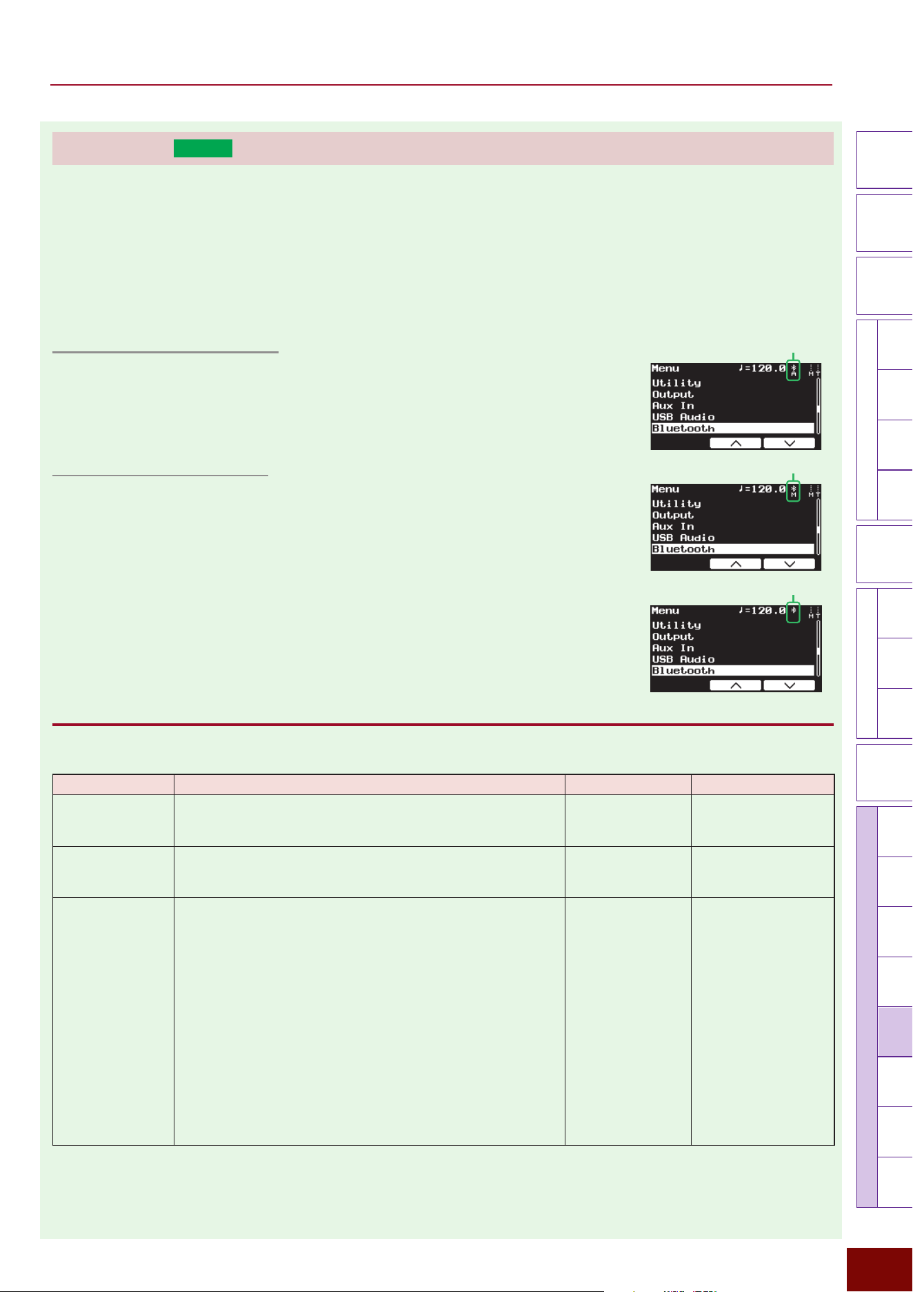
EAD50 EAD20 User Guide
200
Settings in Screens (Parameters)
Modifier
Knobs
LED
Rotary
Faders
[ MIC / TRIG ] [ SCENE ][ CLICK ][ RECORDER ]
[ MENU ]
MicTriggerKitEffectRecorderLooperSamplingUtilityOutputAux In
USB Audio
Bluetooth
FileFactory
Reset
Version
[
LIVE SET
]
Bluetooth (
EAD50
only)
NOTE
Depending on the country in which you purchased the product, the EAD50 may not have Bluetooth capability.
■ Bluetooth (Wireless Audio/MIDI Communication)
This product supports using Bluetooth to receive audio (Bluetooth audio) or send/receive MIDI (Bluetooth MIDI). This setting
sets mainly Bluetooth audio-related settings.
Bluetooth Audio Connection
To establish a Bluetooth audio connection, set the Bluetooth On/Off parameter to “On” and
then pair the devices (described below). When the connection is established, “EAD50
Audio(xxxxxx)” is displayed on the Bluetooth device screen and “A” is displayed below the
Bluetooth icon on the screen.
Bluetooth MIDI Connection
Set the Bluetooth On/Off parameter to “On” and then connect to this product via the
app on the smartphone or other Bluetooth device. Pairing is not necessary. When the
connection is established, “EAD50 MIDI(xxxxxx)” is displayed on the Bluetooth device
screen and “M” is displayed below the Bluetooth icon on the screen.
NOTE
• If no letter is displayed below the Bluetooth icon, then that indicates that both audio and MIDI
communication are enabled.
• Also refer to relevant explanations on Page 50, such as about Bluetooth connection examples.
Bluetooth "Bluetooth
This sets basic Bluetooth settings.
Parameter Explanation Setting Default Value
On/Off This sets whether to use Bluetooth for audio/MIDI
communication (On) or not (Off).
Off, On Always set to “Off”
for Preset Scenes
(Bluetooth).
Volume This adjusts the volume level of audio input via Bluetooth.
0 – 127 Always set to “100”
for Preset Scenes
(Bluetooth).
Pairing Pressing the [ENTER] button starts pairing the Bluetooth
devices. Selecting “EAD50 Audio(xxxxxxxx)” on the Bluetooth
device screen as the device to connect starts pairing the
devices.
NOTE
• Pair the devices within 5 minutes. The “Bluetooth pairing”
message automatically ends after 5 minutes have elapsed. If
prompted to enter a pass key, enter the number “0000”.
• Pairing the Bluetooth devices can also be started by holding
down the [MENU] button.
• The pairing operation is required when connecting a Bluetooth
device to this product for the first time. Once the Bluetooth
device is paired, it does not need to be paired again, unless the
pairing is cancelled in the Bluetooth device.
— —
Bluetooth icon with “A”
Bluetooth icon with “M”
Bluetooth icon (with no letter)
EAD50 EAD20 User Guide
201
Settings in Screens (Parameters)
Modifier
Knobs
LED
Rotary
Faders
[ MIC / TRIG ] [ SCENE ][ CLICK ][ RECORDER ]
[ MENU ]
MicTriggerKitEffectRecorderLooperSamplingUtilityOutputAux In
USB Audio
Bluetooth
FileFactory
Reset
Version
[
LIVE SET
]
Bluetooth "Bluetooth EQ
This sets EQ-related settings for audio inputs via Bluetooth.
NOTE
For more information about equalizers (EQ), refer to the diagrams on Page 32.
Page 1/6
Parameter Explanation Setting Default Value
On/Off This sets whether to apply EQ to audio being input via
Bluetooth (On) or not (Off). The “Off” setting has an equivalent
effect as setting Gain = 0 and HPF Freq = Thru for each
frequency band.
Off, On Always set to “Off”
for Preset Scenes
(Bluetooth).
Page 2/6
Parameter Explanation Setting Default Value
Low Freq This sets the midpoint of the EQ low frequency band for audio
input via Bluetooth.
32Hz – 2.0kHz
Always set to “125Hz”
for Preset Scenes
(Bluetooth).
Low Gain
Used to boost or cut signals near the frequency specified for
Low Freq.
−12dB – 0dB –
+12dB
Always set to “0dB”
for Preset Scenes
(Bluetooth).
Low Q This sets the Q factor (frequency characteristics) for the EQ
low frequency band. If Low Shape is set to LowShelving, then
the Low Q value will have no effect.
0.1 – 12.0 Always set to “0.9”
for Preset Scenes
(Bluetooth).
Low Shape This selects the shape of frequency characteristics for the EQ
low frequency band.
LowShelving,
PeakDip
Always set to
“LowShelving” for Preset
Scenes (Bluetooth).
Page 3/6
Parameter Explanation Setting Default Value
MidLow Freq This sets the midpoint of the low-to-mid frequency band for
EQ applied to audio input via Bluetooth.
100Hz – 10.0kHz
Always set to “500Hz”
for Preset Scenes
(Bluetooth).
MidLow Gain Used to boost or cut signals near the frequency specified for
MidLow Freq.
−12dB – 0dB –
+12dB
Always set to “0dB”
for Preset Scenes
(Bluetooth).
MidLow Q This sets the Q factor (frequency characteristics) for the EQ
low-to-mid frequency band.
0.1 – 12.0 Always set to “0.9”
for Preset Scenes
(Bluetooth).
EAD50 EAD20 User Guide
202
Settings in Screens (Parameters)
Modifier
Knobs
LED
Rotary
Faders
[ MIC / TRIG ] [ SCENE ][ CLICK ][ RECORDER ]
[ MENU ]
MicTriggerKitEffectRecorderLooperSamplingUtilityOutputAux In
USB Audio
Bluetooth
FileFactory
Reset
Version
[
LIVE SET
]
Page 4/6
Parameter Explanation Setting Default Value
MidHigh Freq
This sets the midpoint of the low-to-high frequency band for EQ
applied to audio input via Bluetooth.
100Hz – 10.0kHz
Always set to “4.0kHz”
for Preset Scenes
(Bluetooth).
MidHigh Gain Used to boost or cut signals near the frequency specified for
MidHigh Freq.
−12dB – 0dB –
+12dB
Always set to “0dB”
for Preset Scenes
(Bluetooth).
MidHigh Q This sets the Q factor (frequency characteristics) for the EQ
mid-to-high frequency band.
0.1 – 12.0 Always set to “0.9”
for Preset Scenes
(Bluetooth).
Page 5/6
Parameter Explanation Setting Default Value
High Freq
This sets the midpoint of the high frequency band for EQ
applied to audio input via Bluetooth.
500Hz – 16.0kHz
Always set to “9.0kHz”
for Preset Scenes
(Bluetooth).
High Gain
Used to boost or cut signals near the frequency specified for
High Freq.
−12dB – 0dB –
+12dB
Always set to “0dB”
for Preset Scenes
(Bluetooth).
High Q This sets the Q factor (frequency characteristics) for the EQ
high frequency band. If High Shape is set to HighShelving,
then the High Q value has no effect.
0.1 – 12.0 Always set to “0.9”
for Preset Scenes
(Bluetooth).
High Shape This selects the shape of frequency characteristics for the EQ
high frequency band.
HighShelving,
PeakDip, LPF
Always set to
“HighShelving” for Preset
Scenes (Bluetooth).
Page 6/6
Parameter Explanation Setting Default Value
HPF Freq
Separately from EQ settings, a high-pass filter (HPF) can also
be applied to audio input via Bluetooth. The filter cuts sounds
with frequencies lower than the specified frequency. If “Thru” is
specified, the HPF is not applied.
Thru, 56Hz –
2.0kHz
Always set to “Thru”
for Preset Scenes
(Bluetooth).
HPF Q This sets the Q factor (frequency characteristics) for the high-
pass filter.
0.1 – 12.0 Always set to “0.7”
for Preset Scenes
(Bluetooth).
EAD50 EAD20 User Guide
203
Settings in Screens (Parameters)
Modifier
Knobs
LED
Rotary
Faders
[ MIC / TRIG ] [ SCENE ][ CLICK ][ RECORDER ]
[ MENU ]
MicTriggerKitEffectRecorderLooperSamplingUtilityOutputAux In
USB Audio
Bluetooth
FileFactory
Reset
Version
[
LIVE SET
]
Bluetooth "Bluetooth Out
This sets external output-related settings for audio inputs to this product via Bluetooth.
Page 1/2
Parameter Explanation Setting Default Value
Mode This specifies how to process audio input to this product via
Bluetooth during output.
Stereo
Processes stereo input sounds directly as stereo output.
L Mono
Uses only sound from the left channel.
R Mono
Uses only sound from the right channel.
L+R Mono (L+R monaural)
Mixes the left and right channels and processes it as
monaural sound.
L Guide
Select this setting to input separated audio, with guide (click)
sounds input via the L channel and other backing sounds via
the R channel. The guide (click) sound and backing sound
are output from the [PHONES] jack in the center pan position,
and the backing sound is output from the [OUTPUT] jacks and
[USB TO HOST] terminal in the center pan position. The guide
(click) volume for the [PHONES] jack can be adjusted with the
[CLICK] slider and the backing volume can be adjusted with
the [AUDIO] slider.
R Guide
Select this setting to input separated audio, with guide (click)
sounds input via the R channel and other backing sounds via
the L channel. The guide (click) sound and backing sound are
output from the [PHONES] jack in the center pan position, and
the backing sound is output from the [OUTPUT] jacks and
[USB TO HOST] terminal in the center pan position. The guide
(click) volume for the [PHONES] jack can be adjusted with the
[CLICK] slider and the backing volume can be adjusted with
the [AUDIO] slider.
Stereo, L Mono, R
Mono, L+R Mono, L
Guide, R Guide
Always set to “Stereo”
for Preset Scenes
(Bluetooth).
Main Out For audio that is input to this product via Bluetooth, this sets
whether to output the audio from [OUTPUT] jacks (On) or not
(Off).
Off, On Always set to “On”
for Preset Scenes
(Bluetooth).
Phones Out For audio that is input to this product via Bluetooth, this sets
whether to output the audio from [PHONES] jacks (On) or not
(Off).
Off, On
USB Audio Out
1/2
For audio that is input to this product via Bluetooth, this sets
whether to output the audio from the [USB TO HOST] terminal
(On) or not (Off).
Off, On
Backing Out Level
The setting is displayed when Mode = L Guide or R Guide.
This sets the volume level for backing sound output via the
[OUTPUT] jacks and [USB TO HOST] terminal (USB Audio
1/2). If Mode = L Guide, then R becomes the backing sound,
whereas if Mode = R Guide, then L becomes the backing
sound.
0 – 127 Always set to “127”
for Preset Scenes
(Bluetooth).
EAD50 EAD20 User Guide
204
Settings in Screens (Parameters)
Modifier
Knobs
LED
Rotary
Faders
[ MIC / TRIG ] [ SCENE ][ CLICK ][ RECORDER ]
[ MENU ]
MicTriggerKitEffectRecorderLooperSamplingUtilityOutputAux In
USB Audio
Bluetooth
FileFactory
Reset
Version
[
LIVE SET
]
Page 2/2
Parameter Explanation Setting Default Value
IndivOut For left and right (L + R) audio inputs to this product via
Bluetooth, this sets which channel to use for external output.
Off, L1+R2, L3+R4,
L5+R6, L7+R8,
L(1+2), R(1+2),
L(3+4), R(3+4),
L(5+6), R(5+6),
L(7+8), R(7+8),
L1, R2, L3, R4, L5,
R6, L7, R8, (L+R)1,
(L+R)2, (L+R)3,
(L+R)4, (L+R)5,
(L+R)6, (L+R)7,
(L+R)8
* For a description of
respective setting
values, refer to the
table on page bottom
of Page 116.
Always set to “Off”
for Preset Scenes
(Bluetooth).
IndivOut Vol For audio inputs to this product via Bluetooth, this sets the
volume level for outputting the audio from [INDIVIDUAL
OUTPUT] jacks. If “Variable” is specified, the volume is linked
to [AUDIO] slider operations.
Variable, 1 – 127 Always set to “Variable”
for Preset Scenes
(Bluetooth).
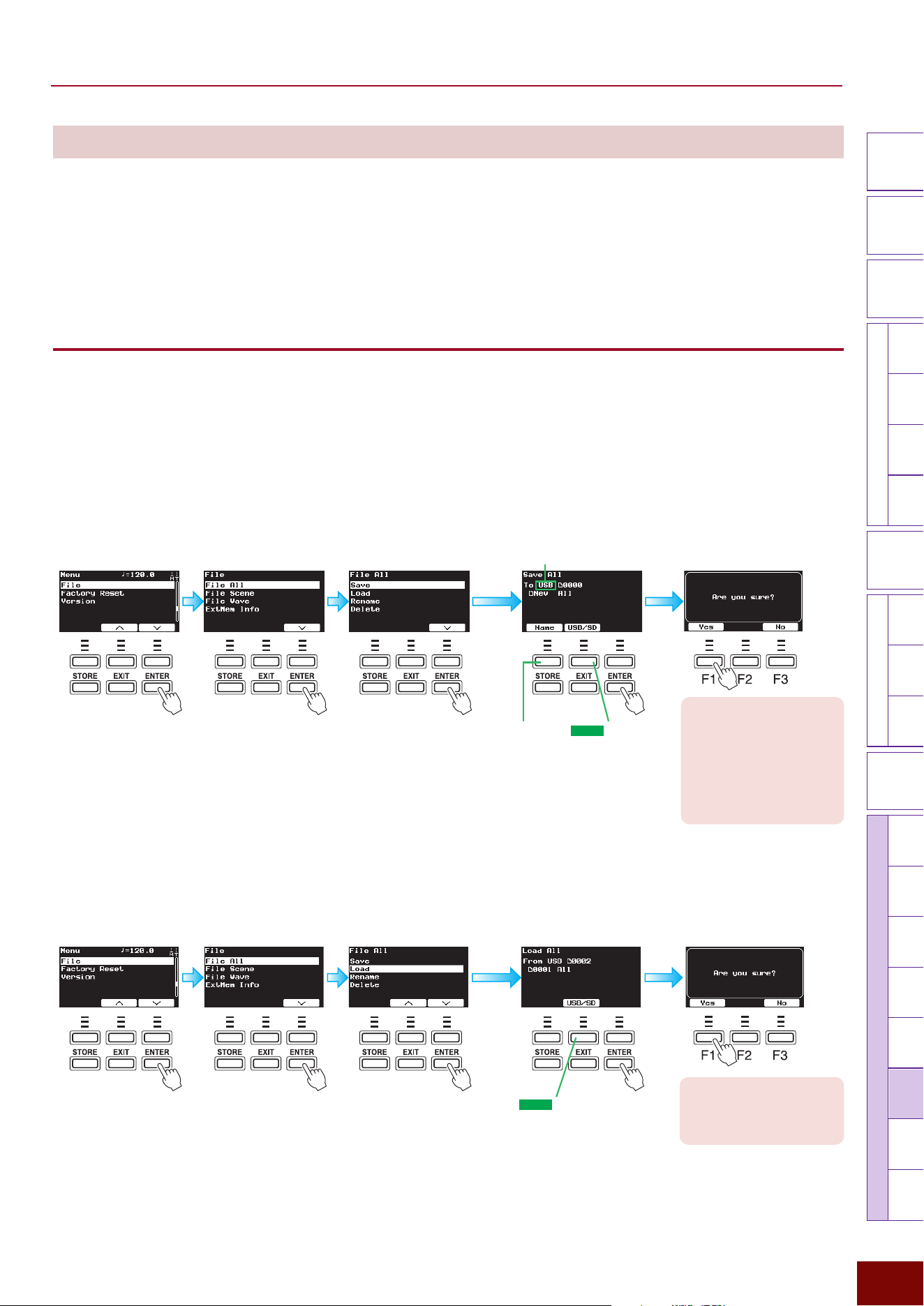
EAD50 EAD20 User Guide
205
Settings in Screens (Parameters)
Modifier
Knobs
LED
Rotary
Faders
[ MIC / TRIG ] [ SCENE ][ CLICK ][ RECORDER ]
[ MENU ]
MicTriggerKitEffectRecorderLooperSamplingUtilityOutputAux In
USB AudioBluetooth
File
Factory
Reset
Version
[
LIVE SET
]
File
This is used for operations related to files saved in external memory connected to the product. For example, it is used to save
data created with the product as files in external memory or to import files saved in external memory into this product.
NOTE
• For an explanation of how internal memory relates to external memory (media), refer to the diagram on Page 33.
• This product supports up to 1000 files with each file extension, whereas the EAD20 supports up to 100 files.
• Although this product can import files saved with “All” and “Scene” of the EAD20, all the settings might not be restored properly.
• “All” or “Scene” files saved in the EAD50 cannot be imported to the EAD20.
File "File All
This operation relates to files (initially named “All.bin”) used to store all Scenes, Live Sets, and User Voices created on this
product.
NOTICE
Note that it does not include audio files and data recorded in internal memory using Recorder, Looper, or Sampling function.
● Save
This saves all Scenes, Live Sets, and User Voices created on this product as “All.bin” (default file name) in external memory. To
save the file, press [F1] to specify a file name and then press [ENTER].
(
EAD50
only)
“USB/SD” is displayed
if both a USB flash
drive and SD card are
connected.
Use this button to select
USB or SD.
If necessary, specify the
saving location file name.
For file naming instructions,
refer to Page 66.
NOTICE
If a file with the same file name
already exists in the media
where the file is being saved, an
“Overwrite?” message is displayed.
If that occurs, changing the file
name, by pressing the [F3] No
button to display the previous screen
again, is recommended.
External Memory for Saving Files
● Load
This imports the “All.bin” file (default file name) saved in external memory into this product.
Use the [+]/[−] buttons or knob to select the file and then press the [ENTER] button to load the file.
(
EAD50
only)
“USB/SD” is displayed if both a
USB flash drive and SD card are
connected.
Use this button to select USB or SD.
Use the [+]/[−] buttons or knob
to select the file to load.
NOTICE
Beware that this operation will
delete all data stored in internal
memory.
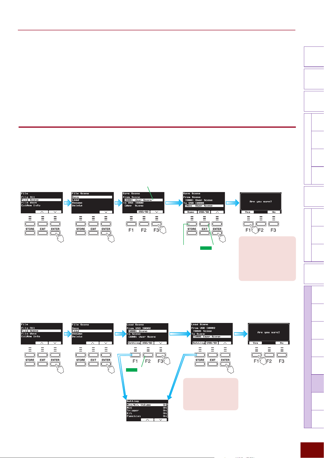
EAD50 EAD20 User Guide
206
Settings in Screens (Parameters)
Modifier
Knobs
LED
Rotary
Faders
[ MIC / TRIG ] [ SCENE ][ CLICK ][ RECORDER ]
[ MENU ]
MicTriggerKitEffectRecorderLooperSamplingUtilityOutputAux In
USB AudioBluetooth
File
Factory
Reset
Version
[
LIVE SET
]
● Rename
This is used to rename the “All.bin” (default file name) file saved in external memory.
Use the [+]/[−] buttons or knob to select the file, press the [F1] Name button to change the file name, and then press the [ENTER]
button to apply the change. For more information, refer to Page 66.
● Delete
This deletes the “All.bin” (default file name) file saved in external memory.
Use the [+]/[−] buttons or knob to select the file and then press the [ENTER] button to delete the file.
File "File Scene
This operation is related to individually storing files for Scenes created on this product (initially named “Scene.bin”).
● Save
This is used to individually save Scenes created on this product as a “Scene.bin” file (initial file name). If the selected Scene
involves a User Voice, then the file also includes User Voice data.
(
EAD50
only)
“USB/SD” is displayed
if both a USB flash
drive and SD card are
connected.
Use this button to select
USB or SD.
If necessary, specify the
saving location file name.
For file naming instructions,
refer to Page 66.
NOTICE
If a file with the same file name
already exists in the media
where the file is being saved, an
“Overwrite?” message is displayed.
If that occurs, changing the file
name, by pressing the [F3] No
button to display the previous
screen again, is recommended.
Select the location for saving
the file. Use the [+]/[−] buttons or
knob to select an existing file or
select a new Scene.
Use the [+]/[−] buttons or knob
to select the Scene to save.
Save the file.
● Load
This imports data from the “Scene.bin” file (default file name) saved in external memory into the product.
Use the [+]/[−] buttons or knob
to select the Scene number for
the loading location.
Use the [+]/[−] buttons or knob
to select the file to load.
Load the file.
NOTICE
All settings for the Scene number
where the file is loaded will be
deleted. Make sure the Scene
where the file is being loaded does
not include important settings.
NOTE
The “F” in “F1 – F3” refers
to “Function” and is used
to name the buttons for
explanatory convenience.
The names are not printed
on the panel.
If necessary, set whether to load
respective parameters within the Scene
(On) or not (Off). For information about
the composition of data in Scenes, refer
to Page 35.
(
EAD50
only)
“USB/SD” is displayed if both a
USB flash drive and SD card are
connected.
Use this button to select USB
or SD.
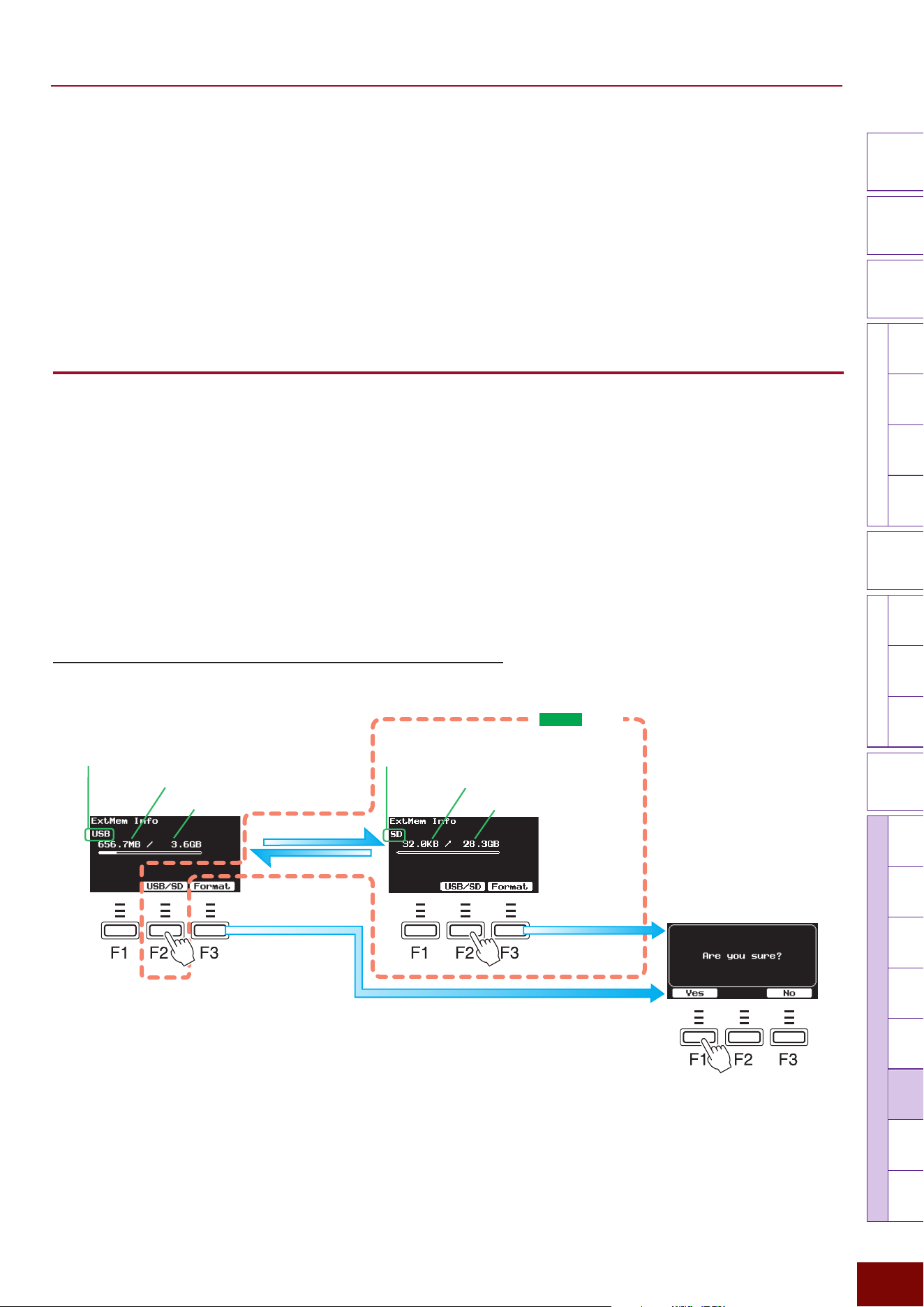
EAD50 EAD20 User Guide
207
Settings in Screens (Parameters)
Modifier
Knobs
LED
Rotary
Faders
[ MIC / TRIG ] [ SCENE ][ CLICK ][ RECORDER ]
[ MENU ]
MicTriggerKitEffectRecorderLooperSamplingUtilityOutputAux In
USB AudioBluetooth
File
Factory
Reset
Version
[
LIVE SET
]
● Rename
This renames Scene files saved in external memory.
Use the [+]/[−] buttons or knob to select the file, press the [F1] Name button to change the file name, and then press the [ENTER]
button to apply the change. For more information, refer to Page 66.
● Delete
This deletes the “Scene.bin” (default file name) file saved in external memory.
Use the [+]/[−] buttons or knob to select the file and then press the [ENTER] button to delete the file.
File "File Wave
This product supports three types of audio files: “.aif”, “.aiff”, and “.wav” files.
● Rename
This renames audio files saved in external memory.
Use the [+]/[−] buttons or knob to select the file, press the [F1] Name button to change the file name, and then press the [ENTER]
button to apply the change.
● Delete
This deletes audio files saved in external memory.
Use the [+]/[−] buttons or knob to select the file and then press the [ENTER] button to delete the file.
File "ExtMem Info (Usage/Format of External Memory)
This Indicates how much of the external memory connected to the product is used.
NOTE
The “F” in “F1 – F3” refers to
“Function” and is used to name
the buttons for explanatory
convenience. The names are
not printed on the panel.
Total capacity of SD card
Total capacity of USB flash drive
SD card memory usage
USB flash drive memory usage
The USB flash drive
memory can be formatted.
The SD card memory
can be formatted.
Press [F1] to format the
memory.
Indicates that this product can
use the SD cards.
Indicates that this product will use
the USB flash drive.
[F2] button
[F2] button
(
EAD50
only)
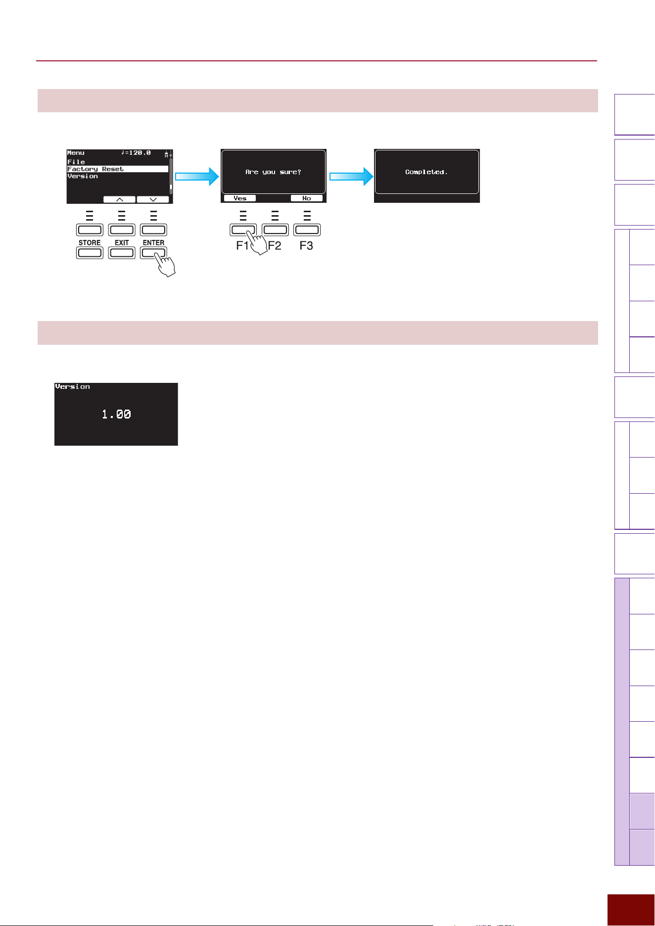
EAD50 EAD20 User Guide
208
Settings in Screens (Parameters)
Modifier
Knobs
LED
Rotary
Faders
[ MIC / TRIG ] [ SCENE ][ CLICK ][ RECORDER ]
[ MENU ]
MicTriggerKitEffectRecorderLooperSamplingUtilityOutputAux In
USB AudioBluetooth
FileFactory
Reset
Version
[
LIVE SET
]
Factory Reset
Resets internal memory to the initial status when shipped from the factory.
Version
Displays the firmware version.
NOTE
The “F” in “F1 – F3” refers to “Function” and is used
to name the buttons for explanatory convenience.
The names are not printed on the panel.
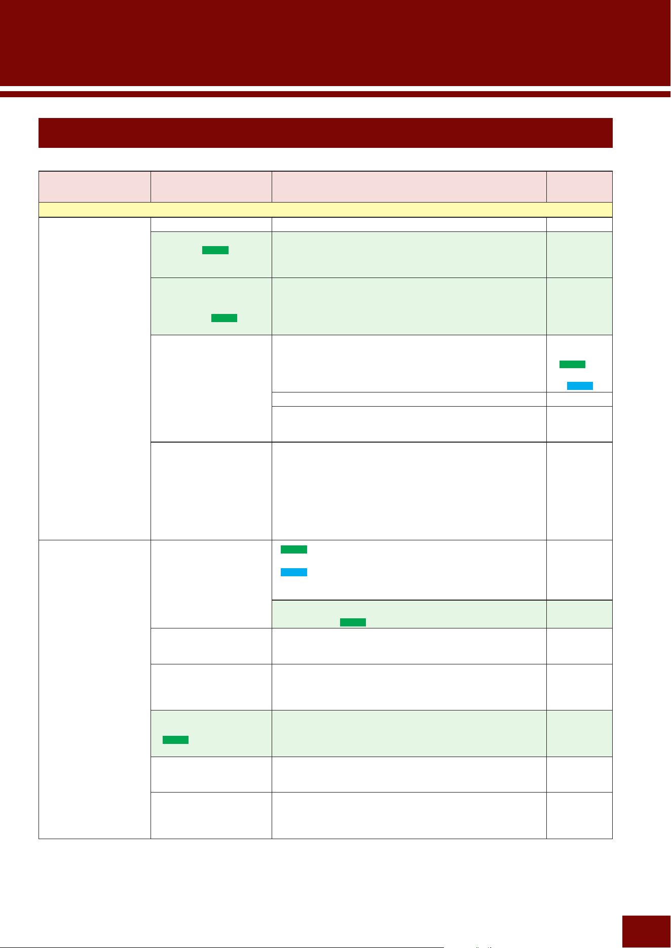
EAD50 EAD20 User Guide
209
Troubleshooting
Problem Possible Causes Solution
Pages
Sound is Not Produced as Expected
No Sound is
Output
Power is not turned On. Check whether the power is on. Quick Guide
How product buttons were
operated (
EAD50
only).
• Check the lamp status of the [MUTE ALL] button located in
the lower left area of the panel.
• Check lamp status of channel on/off buttons (1 – 5)
located in the lower center area of the panel.
7
87
88
Phantom power settings
when a DSU50 unit
or condenser mic is
connected (
EAD50
only).
If a DSU50 unit or condenser mic is connected, no sound will
be produced unless phantom power is On.
Check the phantom power setting on the following in the
screen.
[MIC/TRIG] "[F3] Setting "Mic "Mic In "Phantom
109
A cable is not connected
properly or is switched
off.
Confirm that the Sensor Unit is properly connected to the
main unit (this product).
DSU50
Owner's Manual
(
EAD50
) and
Quick Guide
(
EAD20
)
Check the cables used for any damage/defects. –
Confirm that the headphones, amp, speakers, and other
equipment are properly connected to the main unit (this
product).
–
Individual output
destination settings in
Effect settings
Check the settings on the following screens.
[MIC/TRIG] "[F3] Setting "Mic "Mic Out"Effect Thru
[MIC/TRIG] "[F3] Setting "Kit "Inst "Inst "Inst Out "Effect Thru
If the Effect Thru setting is “On” in the screens above, check
the on/off status for the 3 settings below.
• Main Out (output from the [OUTPUT] jacks)
• Phones Out (output to headphones)
• USB Audio Out1/2 (output to connected computer)
116
132
No sound is
produced or
volume is not the
expected level.
The volume of this
product is not turned up
EAD50
Check the slider positions in the lower right area of the panel.
EAD20
Check the [MASTER] knob located in the left area of the
panel.
7
Check the status of fader LED lamps in the lower center area
of the panel. (
EAD50
only)
87
88
The volume of this
product level is not set
correctly.
Check the volume level of each channel on the following
screen and, if necessary, adjust the volume.
[MIC/TRIG] "[F1] Volume
107
Inadequate gain during
input
Check the input gain to this product on the following screens
and, if necessary, adjust them.
[MIC/TRIG] "[F3] Setting "Mic "Mic In "Gain
[MIC/TRIG] "[F3] Setting "Trigger "Trig In "Pad "Gain
109
119
For mic sound, the shape
of the cable connector
(
EAD50
only)
The [MIC/LINE] jacks are compatible with both TRS phone
plugs and XLR connectors. The gain is lower for TRS phone
plugs. If the gain level does not increase enough using a
TRS phone jack, try using an XLR connector.
8
For mic sound, the Talk
setting
Turning On the Talk setting will increase the input gain values
for mic inputs. If necessary, turn off the Talk setting.
[MIC/TRIG] "[F3] Setting "Mic "Mic In "Talk
112
An external device
connected to this
product
Check both hardware factors, such as the power supply
status, volume level, and slider positions, and also software
factors, such screen settings, for external devices connected
to this product.
–
Appendix
EAD50 EAD20 User Guide
210
Appendix
Problem Possible Causes Solution
Pages
Sound is Not Produced as Expected (continued)
Headphone
volume is low
The volume of this
product is not turned up
EAD50
Check the [PHONES] slider position in the lower right area of
the panel.
EAD20
Check the position of the [MASTER] volume knob in the left
area of the panel.
–
Performance of
headphones being used
To make the EAD sound easier to hear, using an in-ear
monitor that can block external sounds or closed-back
headphones model is recommended. Note that depending
on headphone performance, it may be difficult to hear low-
frequency sounds, such as kick sounds.
–
Parameter settings of this
product
Try changing the gain setting on the following screen.
[MENU] "Output "Output Gain "Phones Out
190
Both [PHONES] jacks
are used
This product is equipped with one standard headphones
jack and one mini stereo jack. However, simultaneously
connecting two headphones via both jacks will decrease the
output of the headphones.
8
Trigger sounds are
not produced or
difficult to produce
(with Trigger
sensors attached
or electronic drum
pads installed)
Product gain settings Check the corresponding pads (corresponding Trigger
Inputs) to make sure the following settings are configured
appropriately.
[MIC/TRIG] "[F3] Setting "Trigger "Trig Pairing
[MIC/TRIG] "[F3] Setting "Trigger "Trig In "Pad "Gain,
Rim Gain, Min Level, Max Level
118
119
Pad type settings of this
product
Check that the pad type setting is appropriate on the
following screen.
[MIC/TRIG] "[F3] Setting "Trigger "Trig In "Pad
"Category, Type
119
MIDI setting is not
appropriate
Check the following setting. No Voice will be emitted if set to
“Off”.
[MENU] "Utility "MIDI Local Control
188
Trigger output level from
connect pads is low
Check the pad Trigger output level adjustment knobs, if
equipped.
–
Flam and roll
sounds cannot be
detected with the
Trigger sounds
(with Trigger
sensors attached
or electronic drum
pads installed)
Settings for this Product Adjust the setting value on the following screen.
[MIC/TRIG] "[F3] Setting "Trigger "Trig In "Pad
"Reject Time
120
A pad with the
position detection
function does not
produce sound
properly (
EAD50
only)
Settings for this Product First, check whether the pad is connected to a [TRIGGER
INPUT] jack that supports the pad position detection function
(
e
/
i
,
r
/
o
,
t
/
!0
).
Next, check the pad type setting on the following screen.
[MIC/TRIG] "[F3] Setting "Trigger "Trig In "Pad
"Category, Type
In addition, on the following screen, check the Voice
assigned to the pad to confirm that it is compatible with
position detection functionality based on the separately
issued Data List “Voice List”.
[MIC/TRIG] "[F3] Setting "Kit "Voice "Voice
"Category, Number
For cymbal pads, also confirm they are oriented in the
correct direction. If oriented incorrectly, it could prevent
adequately maximizing performance.
26
119
134
EAD50 EAD20 User Guide
211
Appendix
Problem Possible Causes Solution
Pages
Sound is Not Produced as Expected (continued)
Pad controls
(such as for pads
equipped on the
XP120SD) do not
function
– This product does not support pad control functionality
(equipped with some electronic drum pads).
–
Preview sounds
are not produced
or volume is low
for audio files in
external memory.
EAD50
[MIC/TRIG] slider position
[MIC/TRIG] sliders also adjust the volume for audio file
previews. Preview the files with the slider in an appropriate
position.
7
EAD20
Position of [MASTER] knob
Adjust the [MASTER] knob. 11
Click sound
cannot be heard or
its volume is low
EAD50
Position of [CLICK] slider
or [MIC/TRIG] slider
Check the [CLICK] slider first and then check the [MIC/TRIG]
slider. [MIC/TRIG] sliders also adjust Click volume. This
is because the click sound in an audio file on the external
memory will be adjusted by the [MIC/TRIG] slider.
7
EAD20
Position of [AUDIO/
CLICK] knob
Adjust the [AUDIO/CLICK] knob. 11
User Voice preview
sounds are not
produced or the
volume is low.
EAD50
[MIC/TRIG] slider position
[MIC/TRIG] sliders also adjust User Voice preview volume.
Preview the files with the slider in an appropriate position.
7
EAD20
Position of [MASTER] knob
Adjust the [MASTER] knob. 11
Volume Balance
The volume balance
between percussion
instruments in the
performance is
poor.
• Balance between
different mic sounds
(
EAD50
only)
• Balance between
Trigger sounds
• Balance between
mic and Trigger
sounds*
* Mic sound:
- Acoustic drum sound
* Trigger sound:
- Electronic sound
produced due to
detection by Trigger
sensors attached to
acoustic drums.
- Electronic sound
produced by playing
electronic drum pads
Adjustment status of LED
rotary faders
(
EAD50
only)
Check the LED lamp status under the following conditions for
the LED rotary faders located in the lower center area of the
panel.
• The [MIC] button and [MIXER] lamp are on (Gain, Volume)
• The [TRIG] button and [MIXER] lamp are on (Volume)
87
Product volume setting Check the volume level of each channel on the following
screen and, if necessary, adjust the volume.
[MIC/TRIG] "[F1] Volume
107
Volume balance
between input
sounds from
connected external
devices and EAD50
performance sound
is poor
Product volume setting Adjust the [AUDIO] slider (audio from external device) and
the [MIC/TRIG] slider (your performance sound) located in
the lower right area of the panel.
7
Volume setting of
external device
connected to this
product
Check the setting. –
EAD50 EAD20 User Guide
212
Appendix
Problem Possible Causes Solution
Pages
Volume Balance (continued)
The volume balance
is poor between
the playback sound
from external
memory (using
the Recorder
function) and the
performance sound
using the product.
Product volume setting Adjust the [AUDIO] slider (playback sound from external
memory) and the [MIC/TRIG] slider (for the performance
sound of the product), which are located in the lower right
area of the panel.
7
Volume is low
for specific drum
sounds, such as
cymbals
Setup positions of the
Sensor Unit and mics
The sound of drums positioned farther from mics, including
sensor units, sometimes becomes quieter. Reconsider the
drum set and mic positions or consider placing additional
mics.
–
The sense of
volume and low-
frequency sound
of the bass drum
is inadequate
Sensor unit and mic
setup status
In order to generate a sense of volume and low-frequency
sound from bass drum performances, the product uses a
method of generating Trigger sounds using the included
Sensor Unit. Therefore, confirm that the Sensor Unit is
properly attached to the bass drum.
–
(
EAD50
only)
To enhance the acoustic bass drum sound, rather than the
Trigger sound, install an additional mic designed specifically
for bass drums. The microphone on the included DSU50
Sensor Unit is tuned to capture sounds from the overall
drum Kit and are not designed specifically for bass drums.
Therefore, we recommend using a commercially available
mic designed specifically for bass drums.
DSU50
Owner’s
Manual
Bass drum Trigger
sounds are not
produced.
The Sensor Unit is not
attached to the bass
drum properly
Confirm that the Sensor Unit is properly fastened to the hoop. –
Bass drum status Try adjusting the Triggers, because the status can be
affected by the type or tension of the bass drum head.
–
Clicks cannot
be heard during
performances
Click volume setting or
volume balance with
other channels
If the Click sound is buried among other sounds, adjust the
Click volume using the following operations.
•
EAD50
: Use the sliders located in the lower right area of
the panel to adjust the balance between the [CLICK] and
other sounds.
•
EAD20
: Adjust the [AUDIO/CLICK] knob.
•
[CLICK]
"
Click
"
Volume
7
11
159
A User Voice
does not produce
sound.
The wave data assigned
to the User Voice was
deleted.
Use one of the screens below to confirm that a WAV file is
assigned to the corresponding Voice.
[MIC/TRIG] "[F3] Setting "Kit "User Voice
"Edit Velocity Limit L/H
[MIC/TRIG] "[F3] Setting "Kit "User Voice "Delete Wave
144
EAD50 EAD20 User Guide
213
Appendix
Problem Possible Causes Solution
Pages
Noise
Noise is an overall
concern (
EAD50
only)
Cable used In particular, if the cable connecting an external device is
long, connecting the cable to an [OUTPUT -UNBALANCED-]
jack (TRS cable) increases the probability of introducing
noise, so connecting it to an [OUTPUT -BALANCED-] jack
(XLR cable) is recommended.
–
The source of
noise cannot be
identified (
EAD50
only)
– Search for the noise source by successively switching each
channel on/off. If the noise disappears when a channel is
switched from on to off, then that channel is producing the
noise.
87
88
Noise occurs
in mic sound
(acoustic drums,
etc.)
Mic is not attached
properly
Use the provided cable ties or other means to immobilize
cables near the Sensor Unit. For the EAD20 model, orienting
the L-shaped plug connected to the Sensor Unit horizontally
will help stabilize the cable position.
Quick
Guide
Confirm that the Sensor Unit is properly fastened to the hoop.
Confirm that there is no physical interference between the
bass drum head and Sensor Unit.
37
Be sure to use the included cable to connect to the Sensor
Unit. For model
EAD50
,using a similarly-shaped lighting
control cable (DMX cable) can cause noise.
41
Adjust the setup to make sure the Sensor Unit is not touching
a drum other than the bass drum, such as a tom.
Quick
Guide
(
EAD50
only)
If an additional mic other than the Sensor Unit is configured,
check the status of vibration around the mic.
–
Gain setting is not
appropriate
Adjust the gain value on the following screen.
[MIC/TRIG] "[F3] Setting "Mic "Mic In "Gain
109
Noise occurs in
Trigger sounds
(with a Trigger
sensor attached
or electronic drum
pads installed)
Mic is not attached
properly
If a Trigger sensor is attached, check the vibration status
around the sensor.
If an electronic drum pad is installed, check the vibration
status around the pad.
–
Gain setting is not
appropriate
Adjust the gain value on the following screen.
[MIC/TRIG] "[F3] Setting "Trigger "Trig In "Pad "Gain
119
Noise occurs
immediately after
turning on the
power (
EAD50
only)
Sometimes noise can
occur while this product
is searching for paired
Bluetooth devices
That is not a malfunction.
If not connecting to a paired Bluetooth device, turn off
Bluetooth for this product on the following screen.
[MENU] "Bluetooth "Bluetooth "On/Off
200
Noise occurs
immediately
after turning on
Bluetooth for the
product. (
EAD50
only)
Howling sound
is produced from
speakers
A mic is positioned too
close to a speaker
In particular, be especially careful of the monitor speaker
orientation when setting up the speaker. Howling
(phenomenon where a loud squeal sound is generated by a
feedback loop between the mic and speaker) is occurring
because a mic is picking up sound from a monitor speaker.
Also beware that if the selected Scene is marked “*1” in the
Scene List (Pages 96 and 102), howling is probably more
likely to occur due to a somewhat higher gain setting.
53
EAD50 EAD20 User Guide
214
Appendix
Problem Possible Causes Solution
Pages
Unexpected sound
Tom resonance
sounds feel
intrusive when
hitting the snare or
kick drum.
The tom bottom head is
resonating
Try removing the bottom head from the tom. –
Hitting a pad once
produces a Trigger
sound twice
(double Trigger)
The Trigger signal
is recognized twice
because the output level
from electronic drum
pads or Trigger sensors
connected to this
product is too high.
For connected electronic drum pads or Trigger sensors
equipped with an output or sensitivity controller, adjust the
controller (decrease the level).
–
Make sure the following product setting (gain) is not too high.
[MIC/TRIG] "[F3] Setting "Trigger "Trig In "Pad "Gain
119
Reduce the Sensitivity* setting value. If that does not resolve
the problem, increase the Reject Time** setting value.
However, beware that increasing it too much will result in
worse response for a series of successive hits.
*
[MIC/TRIG] "[F3] Setting "Trigger "Trig In "Pad
"Sensitivity
** [MIC/TRIG] "[F3] Setting "Trigger "Trig In "Pad
"Reject Time
120
(
EAD50
only)
If a non-Yamaha pad is connected to [TRIGGER INPUT]
jacks (3) to (5), try changing the following setting to “On”.
[MIC/TRIG] "[F3] Setting "Trigger "Trig In "Pad
"Attenuator
121
For the bass drum,
the Sensor Unit is not
fastened to the hoop
properly.
Confirm that there is no physical interference between the
bass drum head and Sensor Unit.
EAD50
Make sure the unit is fastened in accordance with the DSU50
Owner's Manual.
EAD20
Make sure the unit is fastened in accordance with the EAD20
Quick Guide.
37
For bass drums, the
longer its sound, the
more likely it is to cause
a double Trigger.
Make adjustments to shorten the bass drum sound, –
Sound is produced
even when no
hitting.
A different drum
sound from the
one you play is
produced.
Crosstalk occurs
(phenomenon where
a Trigger sound is
produced for a Trigger
signal emitted due to
unintentional vibration)
Set the following setting to an appropriate value in the
following screen.
[MIC/TRIG] "[F3] Setting "Trigger "Trig In "Crosstalk
"Reject Level
123
If the level adjustment knob is attached to the electronic
drum pad which seems be a source of unnecessary sound,
adjust it to an appropriate level.
–
Set the following setting to an appropriate value in the
following screen.
[MIC/TRIG] "[F3] Setting "Trigger "Trig In "Pad "Min Level
120
If a bass drum sound is generated when the snare drum is
hit, reattach the Sensor Unit in a location farther away from
the snare drum. That resolves the problem in some cases.
–
EAD50 EAD20 User Guide
215
Appendix
Problem Possible Causes Solution
Pages
Unexpected Sounds (continued)
Sound is distorted
Volume is increased too
much
EAD50
Adjust the volume sliders located in the lower right area of
the panel.
EAD20
Adjust the volume knobs located in the left area of the panel.
7
11
Product gain settings Make sure the following product setting (gain) is not too high.
[MIC/TRIG] "[F3] Setting "Mic "Mic In "Gain
[MIC/TRIG] "[F3] Setting "Trigger "Trig In "Pad "Gain
109
119
Connection method
used to input audio from
external audio devices or
mics to this product
First, confirm that the output level from the external audio
device is appropriate.
The [MIC/LINE] jacks of
EAD50
are compatible with both
TRS phone plugs and XLR connectors. The gain is lower
for TRS phone plugs. If the sound is distorted even after
reducing the gain level with the XLR connection, try using a
TRS phone plug.
8
Filter settings Check the setting on the following screen for the layer
suspected of having distorted sound.
[MIC/TRIG] "[F3] Setting "Kit "Voice "Voice "Resonance
134
Effect settings Check the distortion or other Effect settings on the following
screen.
[MIC/TRIG] "[F3] Setting "Effect
147
Recorder-related phenomena (Recording, Looping, and Sampling)
Sound from
external audio
devices connected
to this product
cannot be
recorded
Settings for this Product Check the following settings.
[RECORDER] "[F3] Setting "Recorder Rec
"Rec Aux In, Rec USB Audio In 1/2, Rec USB Audio In
3/4, Rec USB Audio In 5/6, Rec USB Audio In 7/8, Rec
Bluetooth *
[RECORDER] "[F3] Setting "Looper Rec
"Rec Aux In, Rec USB Audio In 1/2, Rec USB Audio In
3/4, Rec USB Audio In 5/6, Rec USB Audio In 7/8, Rec
Bluetooth *
[RECORDER] "[F3] Setting "Sampling Rec
"Rec Aux In, Rec USB Audio In 1/2, Rec USB Audio In
3/4, Rec USB Audio In 5/6, Rec USB Audio In 7/8, Rec
Bluetooth *
*
EAD50
only
169
176
182
Cannot record
Click sound.
Settings for this Product Check the following settings.
[RECORDER] "[F3] Setting "Recorder Rec "Rec Click
[RECORDER] "[F3] Setting "Looper Rec "Rec Click
[RECORDER] "[F3] Setting "Sampling Rec "Rec Click
169
176
182
Cannot record in
external memory
The screen is in the
Looper or Sampling
mode
This product includes three types of Recording functions—
Recorder, Looper, and Sampling. Of those, the Looper and
Sampling modes record sounds in the internal memory and
are unrelated to external memory.
174
180
(
EAD50
only)
Both a
USB flash drive and SD
card are connected,
but settings for
specifying which to use
for recording are not
configured properly.
Correctly select the medium to use for Recording. 165
There is insufficient
storage capacity
available in external
memory.
Check the external memory capacity available on the
following screen.
[MENU] "File "ExtMem Info
207
The external memory is
write-protected.
Disable the external memory write protection. –
The external memory
specifications are not
compatible with this
product.
Refer to Page 231. –
EAD50 EAD20 User Guide
216
Appendix
Problem Possible Causes Solution
Pages
Recorder-related phenomena (Recording, Looping, and Sampling) (continued)
Volume is low
when using
the product to
play audio files
stored in external
memory.
Playback volume setting Adjust the following volume controls.
EAD50
: [AUDIO] volume sliders
EAD20
: [AUDIO/CLICK] knobs
7
11
Volume setting during
Recording
Adjust the recording volume to an appropriate level when
using the Recording function of this product.
[RECORDER] "[F3] Setting " Recorder Rec "Rec Gain
[RECORDER] "[F3] Setting "Looper Rec "Rec Gain
[RECORDER] "[F3] Setting "Sampling Rec "Rec Gain
169
176
182
Files stored in
external memory
cannot be played
using the product
or stops before
finishing.
The file format is not
supported
Check the file format and Sampling frequency. 230
External memory
performance is
inadequate.
External memory with at least 4 GB of capacity is
recommended.
For a list of supported USB flash drives, refer to the “List of
functionality checked USB flash drives” (PDF) on the Yamaha
website.
–
Recorded data
disappeared
After recording data in
the product’s internal
memory, the power
was turned off before
the data was saved in
external memory.
Whether recording data with the Recorder, Looper, or by
Sampling, eventually save the recorded data in external
memory.
165
175
183
Audio files cannot
be imported from
external memory
for use in User
Voices.
The available wave
memory for storing User
Voices might be full.
Check the wave memory capacity on the following screen.
[MIC/TRIG] "[F3] Setting "Kit "User Voice "WaveMem
Info
Unneeded wave data can be deleted on the following
screen.
[MIC/TRIG] "[F3] Setting "Kit "User Voice "Delete Wave
144
The file format is not
supported
For the file format supported by this product, refer to the
Specifications.
230
The directory of the
external memory where
the audio file was saved
is not appropriate
Move the audio file to the root directory of the external
memory.
–
No sound is
produced when
recorded data is
replayed or the
volume is low
EAD50
[OUTPUT] slider position
EAD20
Position of [MASTER]
knob
These volume levels are also adjusted during recording.
Adjust the slider to an appropriate position before recording.
7
11
Power supply-related phenomena
The power turns
off automatically.
Auto Power Off function In cases where the power turning off would be problem,
such as during live performances, disable the Auto Power
Off function on the following screen.
[MENU] "Utility "Auto Power Off
188
Power cannot be
turned on
The AC power adapter is
not connected
Check whether the power adapter is connected. –
EAD50 EAD20 User Guide
217
Appendix
Problem Possible Causes Solution
Pages
Data-related
Changed settings
disappeared
The Scene was changed
without storing the
changes
All edits on this product are cleared whenever a different
Scene is selected. If settings are intended for creating a User
Scene, be sure to save the settings via the [STORE] button
before switching the Scene.
95
Power was interrupted
by unplugging the power
cable
Except for data recorded with the Recorder, all the settings
are retained even if the power is turned off. However, the
settings are not retained if the power is interrupted by
unplugging the cable.
–
Settings are
not changed as
expected after
switching Scenes.
Alternatively,
unintended
settings were
changed.
A setting recalled during
Scene selection was not
set appropriately.
Check the settings on the following screens.
[SCENE] "[F3] Setting "Scene Load
35
92
Data cannot be
saved in external
memory.
The external memory
specifications are not
compatible with the
product.
For information about the USB flash drive which this product
supports, check the support page on the Yamaha website.
–
If not recognized by the product, use the product to reformat
the external memory.
[MENU] "File "ExtMem Info
207
Check the external memory capacity available on the
following screen.
[MENU] "File "ExtMem Info
207
Check whether the external memory is write-protected. –
Smart device/computer-related
Cannot
communicate with
smart devices via
a wired connection
— Check the connection method. For more details, refer to the
Smart Device Connection manual (PDF).
–
A USB cable (USB-C
to Lightning cable) was
used to connect to an
iOS smart device.
If connected using a USB cable (USB-C to Lightning cable),
this product will become the host. To ensure the smart
device is the host, use a Lightning-USB3 camera adapter to
connect to an iOS smart device.
–
Cannot connect/
communicate with
smart devices or
other Bluetooth
devices (
EAD50
only).
— Check the connection method. For more details, refer to the
Smart Device Connection manual (PDF).
–
Bluetooth is off for this
product.
Set the Bluetooth setting to “On” on the following screen.
[MENU] "Bluetooth "Bluetooth "On/Off
200
The smart device
Bluetooth setting is “Off”.
Change the smart device Bluetooth setting to “On”. –
This product is
not paired with the
connected Bluetooth
device
Change the smart device Bluetooth setting to “On” and then
hold down the [MENU] button on this product. That starts
pairing the devices.
200
A device that emits
electromagnetic waves,
such as a microwave
oven or wireless LAN
device, is located
nearby.
Use this product in a location away from products that emit
electromagnetic waves in the 2.4 GHz band.
–
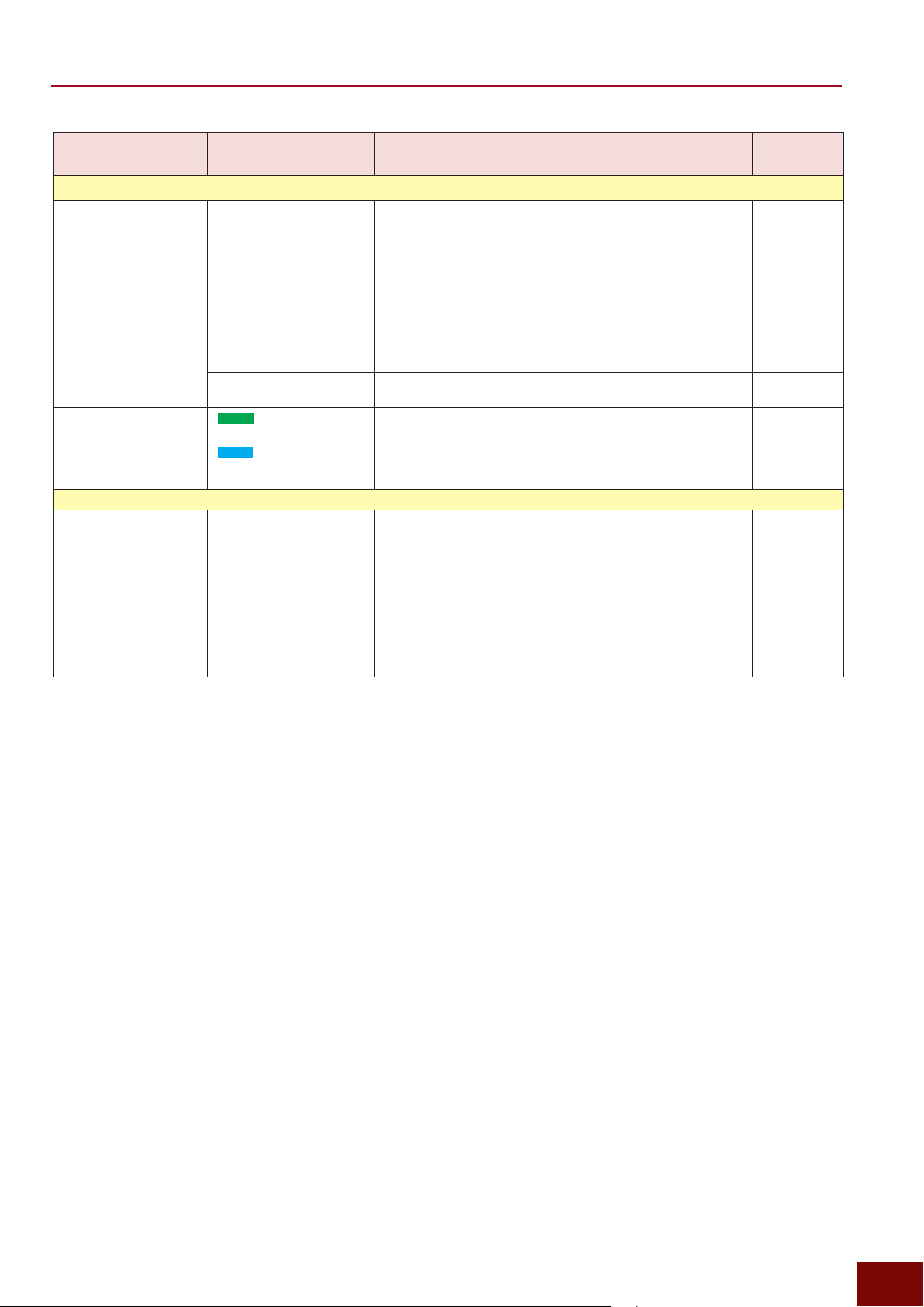
EAD50 EAD20 User Guide
218
Appendix
Problem Possible Causes Solution
Pages
Smart Device/Computer-Related (continued)
Cannot
communicate
with DAW or other
software on a
computer
A driver was not installed
in the computer
For Windows operating systems, the Yamaha Steinberg USB
Driver must be installed.
49
This product turned off or
shut off on its own while
application software
such as DAW was being
operated.
It this product is shut off while it is connected to a computer
(DAW), communication with the computer might not be
restored by simply turning the power on again in some
cases. In such cases, temporarily close the application
software, turn this product off and on, and then restart the
software application in the computer. When connecting to the
computer, setting the Auto Power Off setting to “Off” on the
following screen is recommended.
[MENU] "Utility "Auto Power Off
188
The USB cable is not
connected correctly
Confirm that the USB Cable is correctly connected. –
Audio sound
output to the
computer cannot
be heard or its
volume is low
EAD50
[OUTPUT] slider position
EAD20
Position of [MASTER] knob
For model EAD50, the [OUTPUT] sliders also adjust the
volume for outputs to a computer via the [USB TO HOST]
terminal. Adjust the slider to an appropriate position. For
information about what each slider adjusts, refer to Page 7.
–
MIDI-related
A connected
external MIDI tone
generator does not
produce sound
MIDI specifications of the
connected device
If connected to the [USB TO HOST] terminal, MIDI
communication is only possible between this product and
MIDI devices with the same USB Trigger link functionality.
Note that for MIDI devices without that functionality, MIDI
communication is not possible even if physically connected.
139
The MIDI channel does
not match
Check the MIDI settings on the following screens and the
MIDI settings on the external device.
[SCENE] "[F3] Setting "Modifier "CC Channel, CC Port
[MIC/TRIG] "[F3] Setting "Kit "Voice "Voice MIDI
"Note Ch, Note Port, CC Channel, CC Port
94
138
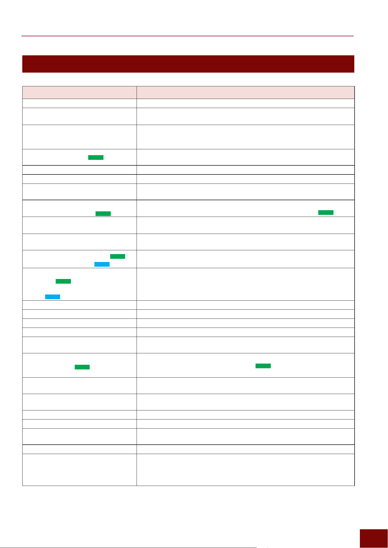
EAD50 EAD20 User Guide
219
Appendix
Message List
Message Explanation
Are you sure?
Displayed to confirm whether to execute respective operations.
Auto power off is disabled.
Energy consumption might increase.
Displayed if the Auto Power Off function was disabled by holding down the
[MENU] button while turning on the power.
Backup error.
Displayed when power is turned on, if writing (saving) data to internal memory
failed when power was turned off the previous time. If this message is
displayed, settings are automatically reset to factory default settings.
Bluetooth pairing.... (
EAD50
only)
This indicates that the system is waiting to be paired with a separate Bluetooth
device. For more information, refer to Page 200.
Canceled.
Displayed when the cancel process is finished.
Can’t process.
The process failed.
Completed.
Displayed when a process such as storing a Scene, loading/saving a file, or
executing a job is completed.
Connecting USB device...
Connecting SD card… (
EAD50
only)
This indicates the product is trying to recognize a USB flash drive connected to the
[USB TO DEVICE] terminal or an SD card inserted in the SD card slot (
EAD50
only).
Energy consumption might increase
depending on the setting.
Displayed if a change to the Auto Power Off setting was attempted.
Excessive demand for USB power.
This indicates that the USB flash drive connected to the [USB TO DEVICE]
terminal is consuming more power than specified.
External memory not ready. (
EAD50
)
USB device not ready. (
EAD20
)
Displayed if an external memory device is not inserted properly into the main
unit.
External memory's transfer speed
too slow. (
EAD50
)
USB device's transfer speed too
slow. (
EAD20
)
Displayed when the data transfer speed to external memory was not fast
enough.
For a list of various devices with functionality verified by Yamaha, refer to the
“List of Devices with Functionality Checked” on the Yamaha website.
Factory Reset initializing ...
Displayed if settings are reset to factory settings during startup.
File already exists.
A file with the same name already exists.
File not found.
There is no file of the selected type.
Illegal file.
Displayed if the file being loaded is not supported by this product.
Incompatible USB device.
Displayed if a USB device not compatible with this product is connected to the
[USB TO DEVICE] terminal.
Invalid USB device
Invalid SD card (
EAD50
only)
This indicates the USB flash drive connected to the [USB TO DEVICE] terminal
or the SD card inserted in the SD card slot (
EAD50
only) is defective. Use the
product to format (Page 207) the device and then try again.
No data.
Displayed if no applicable data is available for executing Recorder or wave-
related functionality.
No response from USB device.
There is no response from the USB device connected to [USB TO DEVICE]
terminal.
Now importing...
Displayed during importing.
Now loading...
Displayed during loading of files.
Now processing...
Displayed during storing of Scenes or executing other functionality.
Displayed during post-processing when file loading/saving is canceled.
Now saving...
Displayed during saving of files.
Overwrite?
Displayed in the following situations.
• When saving a file, a file with the same name already exists in the external
memory.
• Displayed when attempting to store a User Scene that was previously stored.
EAD50 EAD20 User Guide
220
Appendix
Message Explanation
Please keep power on.
Data is being written in internal memory. Do not turn off the power.
Please reboot to enable the new
USB Audio Mode.
Displayed after a USB audio mode setting was changed. Settings are enabled
after the power is turned off and on.
Please stop Recorder.
Displayed when a specific operation is performed during recording with the
Recorder. Stop the Recorder before performing the operation.
Read only file.
Displayed if a file operation is performed with a read-only file selected.
Recording time limit exceeded.
Displayed when the recording time limit is reached while recording with the
Recorder. The time limit is about 1 minute and 30 seconds when using internal
memory or 90 minutes when using external memory. It is also displayed if the
external memory becomes full during recording.
Sample is too long.
The sample is too long to load.
Sample is too short.
The sample is too short to load.
Shutdown
The power supply is being shut down. Do not unplug the AC power adapter until
the message disappears.
USB device connection terminated.
SD card connection terminated.
(
EAD50
only)
The connection was terminated due to an abnormal electrical current level in the
external memory. Disconnect the external memory device and then press the
[OK] button.
USB device full.
SD card full. (
EAD50
only)
Displayed if the file cannot be saved because the external memory is full.
Either prepare a new external memory device or delete unnecessary files and
then try the operation again.
USB device list full.
SD card list full. (
EAD50
only)
Displayed if new data cannot be recorded because the external memory
reached its file count capacity. Either prepare a new external memory device or
delete unnecessary files and then try the operation again.
USB device read/write error.
SD card read/write error. (
EAD50
only)
An error occurred while reading/writing to external memory.
USB device transmission error.
An error occurred while communicating with the USB device.
USB device write protected.
SD card write protected. (
EAD50
only)
Displayed if the external memory device is write protected.
User Voice Bank full.
Displayed if the total number of User Voice banks exceeded the maximum.
User Voice full.
Displayed if the total number of User Voices exceeded the maximum.
Wave full.
Displayed if the total number of waveforms exceeded the maximum.
Wave memory error.
Displayed if writing data to wave ROM memory failed.
Displayed the next time the power is turned on if wave data could not be saved
properly.
After the error message is displayed, a process for restoring the data is
executed automatically.
Wave memory full.
Displayed if a file cannot be imported or a job loaded/processed because
waveform memory is full.
EAD50 EAD20 User Guide
221
Appendix
Content List
This product is equipped with the following content.
Content Selection Screen
Location
Listed/
Indicated
Scene
[SCENE] Page 96
Inst
[MIC/TRIG] "[F3] Setting "Kit "Inst "Inst "Category, Number
Data List
Voices
[MIC/TRIG] "[F3] Setting "Kit "Voice "Voice "Category, Number
Data List
Effect Type
Data List
Reverb Type
[MIC/TRIG] "[F3] Setting "Effect "Reverb "Category, Type
Data List
FX1 Type
[MIC/TRIG] "[F3] Setting "Effect "FX1 "Category, Type
Data List
FX2 Type
[MIC/TRIG] "[F3] Setting "Effect "FX2 "Category, Type
Data List
Ins1 Mic
[MIC/TRIG] "[F3] Setting "Effect "Ins1 Mic "Category, Type
Data List
Ins2 Mic
[MIC/TRIG] "[F3] Setting "Effect "Ins2 Mic "Category, Type
Data List
Ins Trig
[MIC/TRIG] "[F3] Setting "Effect "Ins Trig "Category, Type
Data List
Master FX
[MIC/TRIG] "[F3] Setting "Effect "Master FX "Category, Type
Data List
Master Comp
[MIC/TRIG] "[F3] Setting "Effect "Master Comp "Category, Type
Data List
Phones EQ
[MENU] "Output "Phones EQ "Type
Data List
Of the content indicated above, all data other than Scenes is listed in the separately provided data list.
The data list can be obtained from the following website.
Yamaha Download Site: https://yamaha.com/support/
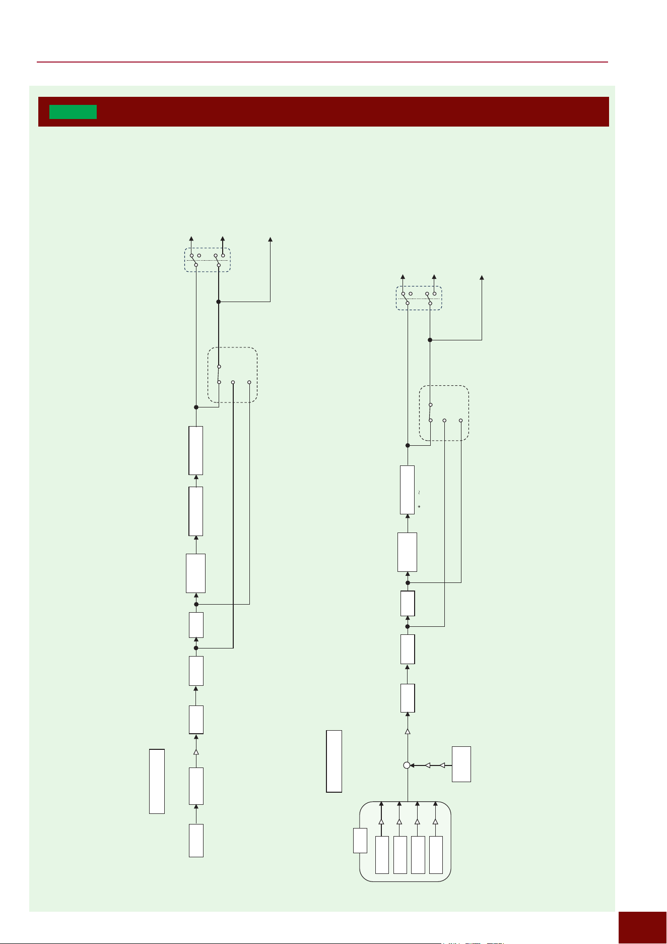
EAD50 EAD20 User Guide
222
Appendix
EAD50
Block Diagram
Trigger Effect Block
Mic EffectBlock
Mic Effect Block
Trigger Effect Block
Real Ambi Depth Trig
Gate Delay EQ
Transient
compressor
Insertion Effect1 Insertion Effect2
Mic In
Main Out, Phones OUT, USB Audio Out 1/2,
Recorder Rec, Looper Rec, Sampling Rec
Phase
Noise Gate
System Effect/Master Effect
EQ Tran Thru
Individual Out
Effect Thru
Tran Thru
Off
EQ Thru
Gate Delay EQ
Transient
compressor
Insertion Effect
Main Out, Phones OUT, USB Audio Out 1/2,
Recorder Rec, Looper Rec, Sampling Rec
Phase
System Effect/Master Effect
EQ Tran Thru
Individual Out
Effect Thru
Tran Thru
Off
EQ Thru
Voice
Layer A
Inst
Voice
Layer B
Voice
Layer C
Voice
Layer D
Real Ambi
Inst
Real Ambi Depth All
+
( Kick Trig17 Only)
Volume
Volume
Volume
Volume
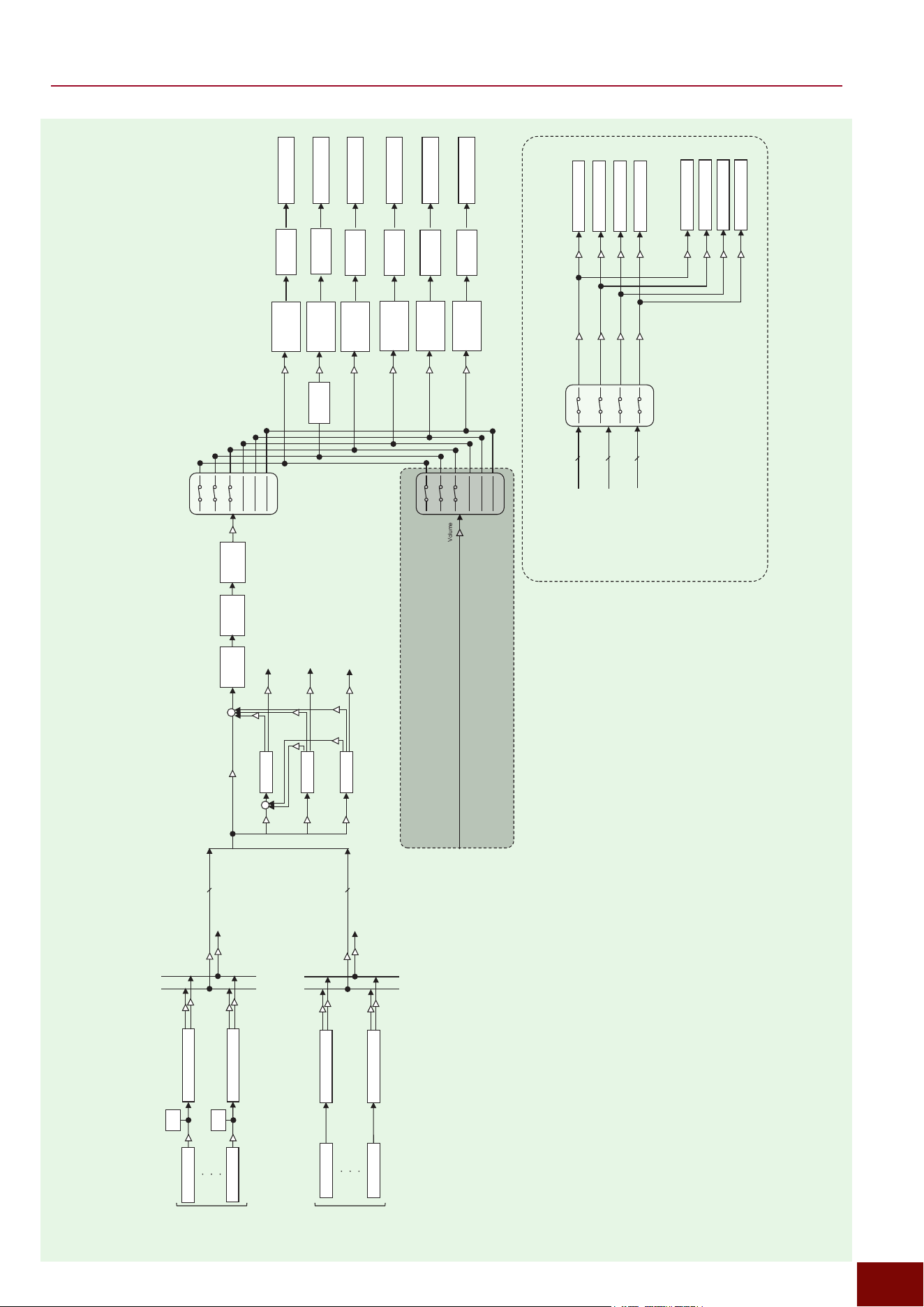
EAD50 EAD20 User Guide
223
Appendix
Block Diagram (Mic/Trigger, Effect Thru Off)
[OUTPUT]
Slider
[PHONES]
Slider
Main Out
Recorder Rec
Sampling Rec
USB Audio Out 1/2
Phones Out
Gain
Gain
Volume
[MIC/TRIG]
[CLICK]
[AUDIO]
Slider
Looper Rec
Gain
[MIC/TRIG]
[CLICK]
[AUDIO]
Slider
[MIC/TRIG]
[CLICK]
[AUDIO]
Slider
[MIC/TRIG]
[CLICK]
[AUDIO]
Slider
[MIC/TRIG]
[CLICK]
[AUDIO]
Slider
[MIC/TRIG]
[CLICK]
[AUDIO]
Slider
[OUTPUT]
Slider
[OUTPUT]
Slider
[OUTPUT]
Slider
[OUTPUT]
Slider
Phones
EQ
Gain
Gain
Gain
Reverb
Master
FX
FX1
FX2
Master
Comp
Master
EQ
Volume
+
+
Volume
Kick~Trig22
To
IndivOut
Return
Return
Return
Return
IndivOut
Return
IndivOut
Return
IndivOut
To
IndivOut
To
IndivOut
To
IndivOut
Dry Level
Send
Send
Send
Send
Send
Volume
Mic1~Mic5
To
IndivOut
Individual Out
Volume
Volume
Volume
Volume
Kick~Trig22
Mic1~Mic5
From
Mic
From
Trigger
Individual Out 1/2
Individual Out 3/4
Individual Out 5/6
Individual Out 7/8
USB Audio Out 3/4
USB Audio Out 5/6
USB Audio Out 7/8
USB Audio Out 9/10
Gain
Gain
Gain
Gain
Gain
Gain
Gain
Gain
Reverb/FX1/FX2
From
Reverb/FX1/FX2
Selector
Trigger Effect Block
Trigger Effect Block
Kick
Trig22
Trigger
(Inst)
Mic
Mic Effect Block
Mic1
Mic Effect Block
Mic5
Level
Meter
Gain
Gain
Level
Meter
Volume
Volume
Volume
Volume
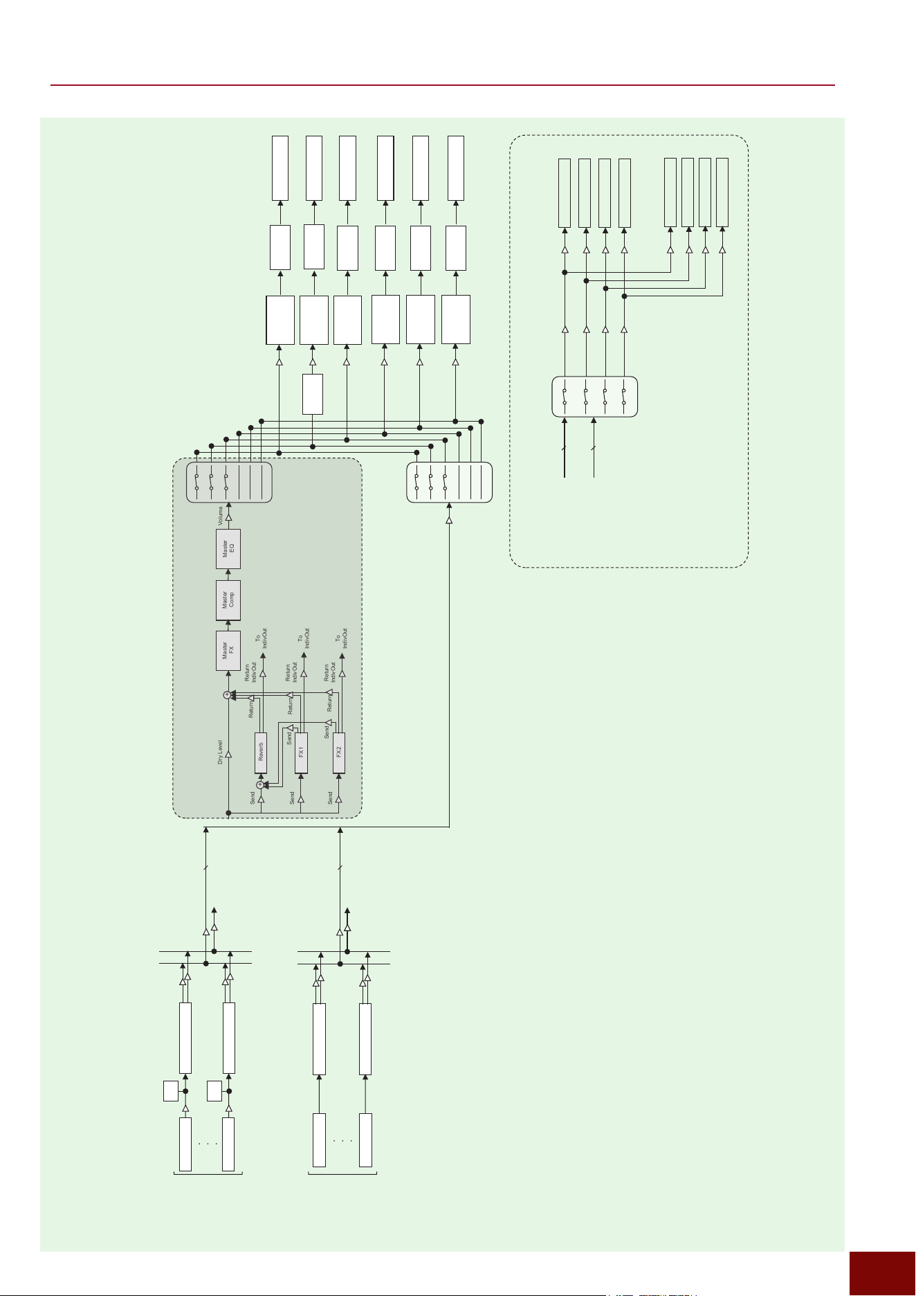
EAD50 EAD20 User Guide
224
Appendix
Block Diagram (Mic/Trigger, Effect Thru On)
Volume
Reverb
Master
FX
FX1
FX2
Master
Comp
Master
EQ
Volume
+
+
Volume
Kick~Trig22
Return
Return
Return
Return
IndivOut
Return
IndivOut
Return
IndivOut
To
IndivOut
To
IndivOut
To
IndivOut
Dry Level
Send
Send
Send
Send
Send
Volume
Mic1~Mic5
To
IndivOut
Individual Out
Volume
Volume
Volume
Volume
Kick~Trig22
Mic1~Mic5
From
Mic
From
Trigger
Individual Out 1/2
Individual Out 3/4
Individual Out 5/6
Individual Out 7/8
USB Audio Out 3/4
USB Audio Out 5/6
USB Audio Out 7/8
USB Audio Out 9/10
Gain
Gain
Gain
Gain
Gain
Gain
Gain
Gain
Selector
Trigger Effect Block
Trigger Effect Block
Kick
Trigger
(Inst)
Volume
Volume
Mic
Mic Effect Block
Mic1
Mic Effect Block
Mic5
Level
Meter
Gain
Gain
Level
Meter
Volume
Volume
Trig22
To
IndivOut
[OUTPUT]
Slider
[PHONES]
Slider
Main Out
Recorder Rec
Sampling Rec
USB Audio Out 1/2
Phones Out
Gain
Gain
[MIC/TRIG]
[CLICK]
[AUDIO]
Slider
Looper Rec
Gain
[MIC/TRIG]
[CLICK]
[AUDIO]
Slider
[MIC/TRIG]
[CLICK]
[AUDIO]
Slider
[MIC/TRIG]
[CLICK]
[AUDIO]
Slider
[MIC/TRIG]
[CLICK]
[AUDIO]
Slider
[MIC/TRIG]
[CLICK]
[AUDIO]
Slider
[OUTPUT]
Slider
[OUTPUT]
Slider
[OUTPUT]
Slider
[OUTPUT]
Slider
Phones
EQ
Gain
Gain
Gain
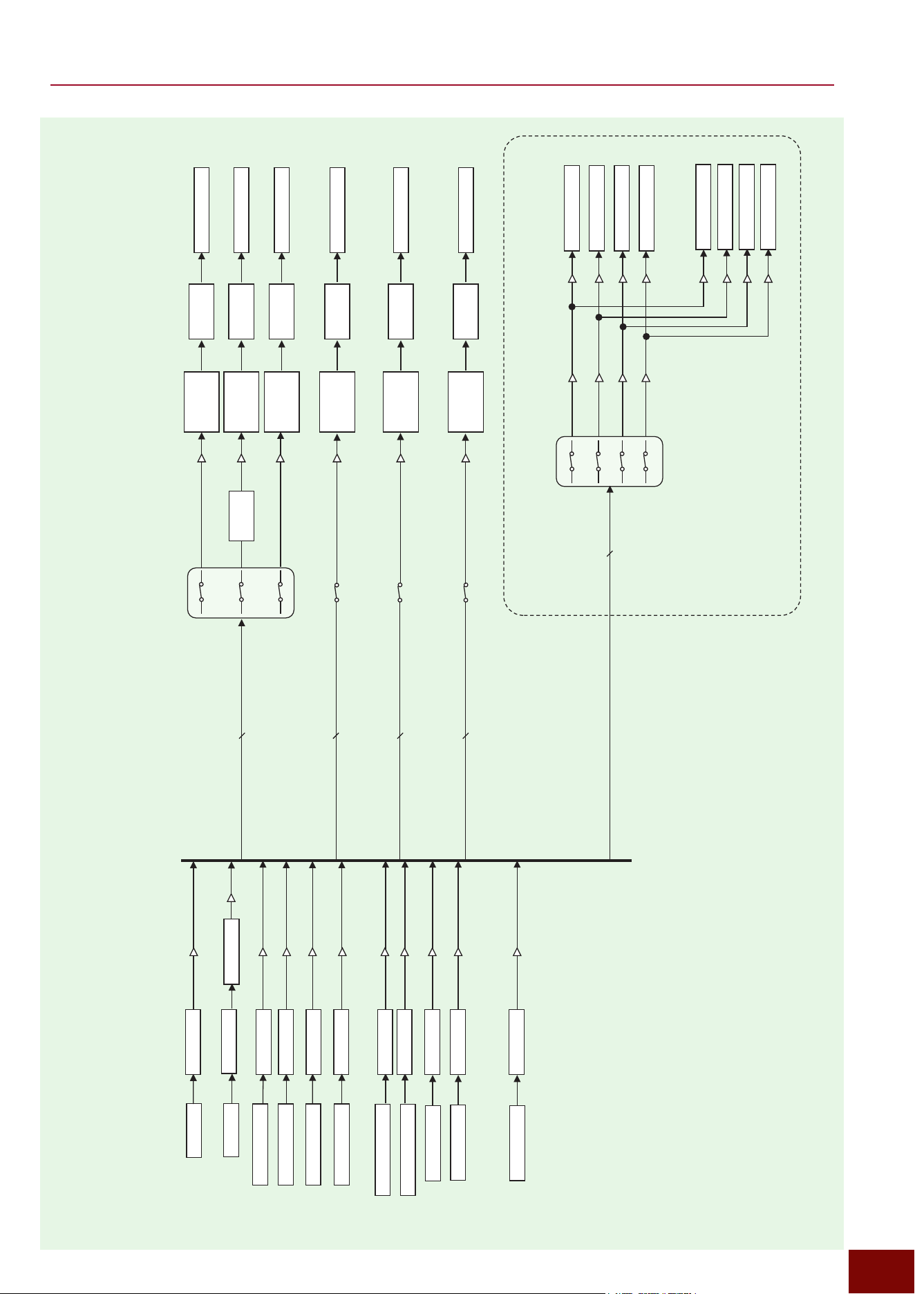
EAD50 EAD20 User Guide
225
Appendix
Aux In
Noise Gate
USB Audio In 1/2
USB Audio In 3/4
USB Audio In 5/6
USB Audio In 7/8
EQ
EQ
EQ
EQ
EQ
EQ
EQ
EQ
Bluetooth
Recorder Playback1
Recorder Playback2
Looper Play
Click
EQ
EQ
EQ
Sampling Play
Recorder Rec
On/Off
Looper Rec
On/Off
Sampling Rec
On/Off
Click, Aux In, USB Audio In1/2~7/8,
Recorder PlayBack1~2, Looper Play, Sampling Play,
Bluetooth
Click, Aux In, USB Audio In1/2~7/8,
Recorder PlayBack1~2,
Bluetooth
Click, Aux In, USB Audio In1/2~7/8,
Bluetooth
Click, Aux In, USB Audio In1/2~7/8,
Bluetooth
[OUTPUT]
Slider
[PHONES]
Slider
Main Out
Recorder Rec
Sampling Rec
USB Audio Out 1/2
Phones Out
Gain
Gain
[MIC/TRIG]
[CLICK]
[AUDIO]
Slider
Looper Rec
Gain
[MIC/TRIG]
[CLICK]
[AUDIO]
Slider
[MIC/TRIG]
[CLICK]
[AUDIO]
Slider
[MIC/TRIG]
[CLICK]
[AUDIO]
Slider
[MIC/TRIG]
[CLICK]
[AUDIO]
Slider
[MIC/TRIG]
[CLICK]
[AUDIO]
Slider
[OUTPUT]
Slider
[OUTPUT]
Slider
[OUTPUT]
Slider
[OUTPUT]
Slider
Gain
Gain
Gain
Click, Aux In, USB Audio In1/2~7/8,
Recorder PlayBack1~2, Looper Play,
Bluetooth
Volume
Volume
Volume
Volume
Volume
Volume
Volume
Volume
Volume
Volume
Volume
Block Diagram (Audio Channel)
Individual Out
Volume
Volume
Volume
Volume
Individual Out 1/2
Individual Out 3/4
Individual Out 5/6
Individual Out 7/8
USB Audio Out 3/4
USB Audio Out 5/6
USB Audio Out 7/8
USB Audio Out 9/10
Gain
Gain
Gain
Gain
Gain
Gain
Gain
Gain
Phones
EQ
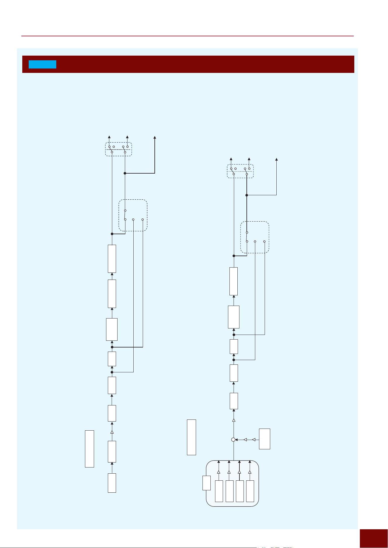
EAD50 EAD20 User Guide
226
Appendix
EAD20
Block Diagram
Trigger Effect Block
Mic EffectBlock
Mic Effect Block
Trigger Effect Block
Real Ambi Depth Trig
Gate Delay EQ
Transient
compressor
Insertion Effect1 Insertion Effect2
Mic In
Main Out, Phones OUT, USB Audio Out 1/2,
Recorder Rec, Looper Rec, Sampling Rec
Phase
Noise Gate
System Effect/Master Effect
EQ Tran Thru
USB Audio Out
Effect Thru
Tran Thru
Off
EQ Thru
Gate Delay EQ
Transient
compressor
Insertion Effect
Main Out, Phones OUT, USB Audio Out 1/2,
Recorder Rec, Looper Rec, Sampling Rec
Phase
System Effect/Master Effect
EQ Tran Thru
USB Audio Out
Effect Thru
Tran Thru
Off
EQ Thru
Voice
Layer A
Inst
Voice
Layer B
Voice
Layer C
Voice
Layer D
Real Ambi
Inst
Real Ambi Depth All
+
Volume
Volume
Volume
Volume
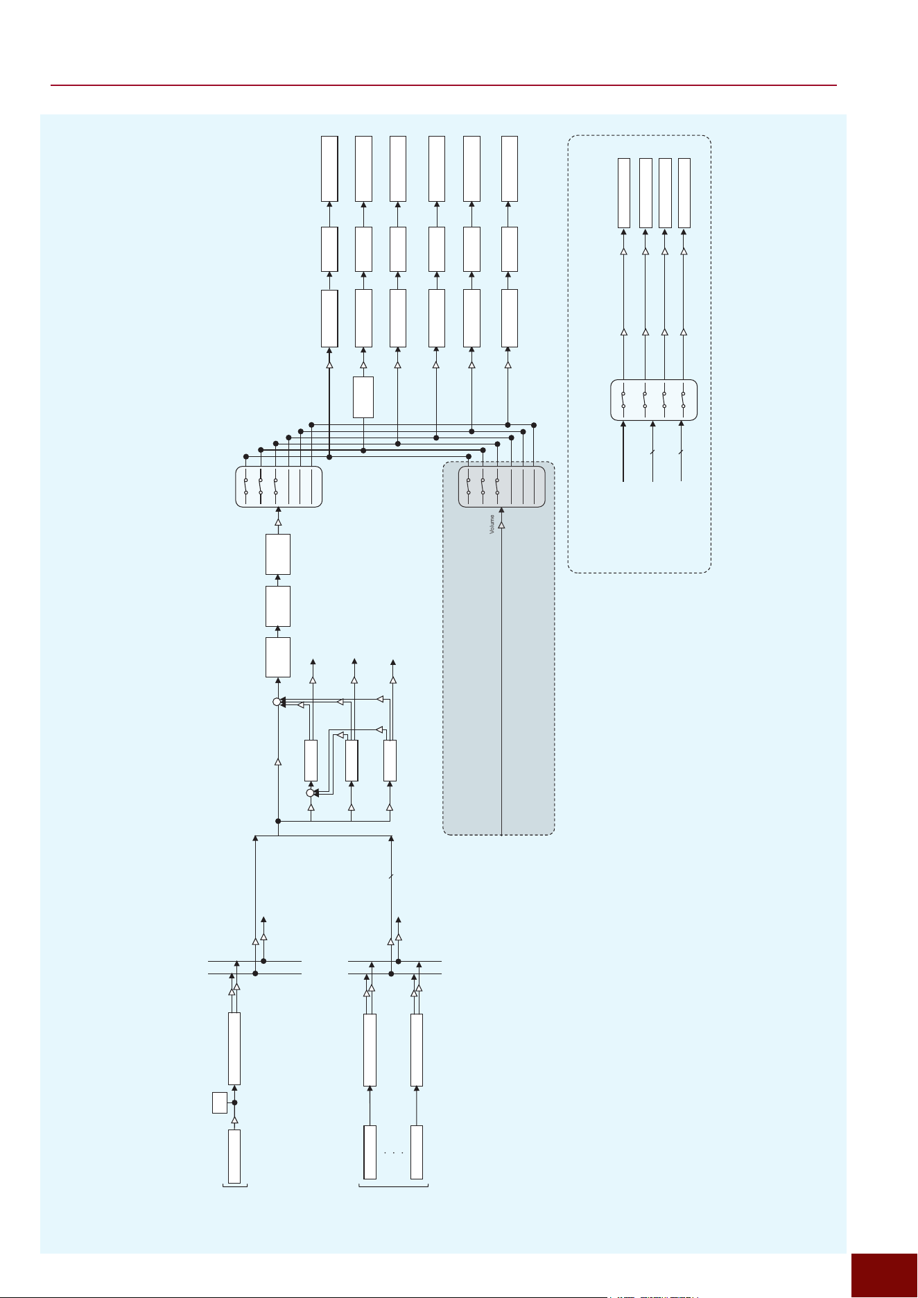
EAD50 EAD20 User Guide
227
Appendix
Block Diagram (Mic/Trigger, Effect Thru Off)
Volume
Reverb
Master
FX
FX1
FX2
Master
Comp
Master
EQ
Volume
+
+
Volume
Kick~Trig10
Return
Return
Return
Return
IndivOut
Return
IndivOut
Return
IndivOut
To
IndivOut
To
IndivOut
To
IndivOut
Dry Level
Send
Send
Send
Send
Send
Volume
To
IndivOut
Trigger Effect Block
Trigger Effect Block
Kick
Trig10
Trigger
(Inst)
Volume
Volume
USB Audio Out
Volume
Volume
Volume
Volume
Kick~Trig10
From
Mic
From
Trigger
Gain
Gain
Gain
Gain
Reverb/FX1/FX2
From
Reverb/FX1/FX2
Selector
USB Audio Out 3/4
USB Audio Out 5/6
USB Audio Out 7/8
USB Audio Out 9/10
Mic Mic Effect Block
Mic
Gain
Level
Meter
Volume
To
IndivOut
Phones
EQ
[MASTER]
Knob
Main Out
Recorder Rec
Sampling Rec
USB Audio Out 1/2
Phones Out
Looper Rec
[AUDIO/CLICK]
Knob
[MASTER]
Knob
[AUDIO/CLICK]
Knob
[MASTER]
Knob
[AUDIO/CLICK]
Knob
[MASTER]
Knob
[AUDIO/CLICK]
Knob
[MASTER]
Knob
[AUDIO/CLICK]
Knob
[MASTER]
Knob
[AUDIO/CLICK]
Knob
Gain
Gain
Gain
Gain
Gain
Gain
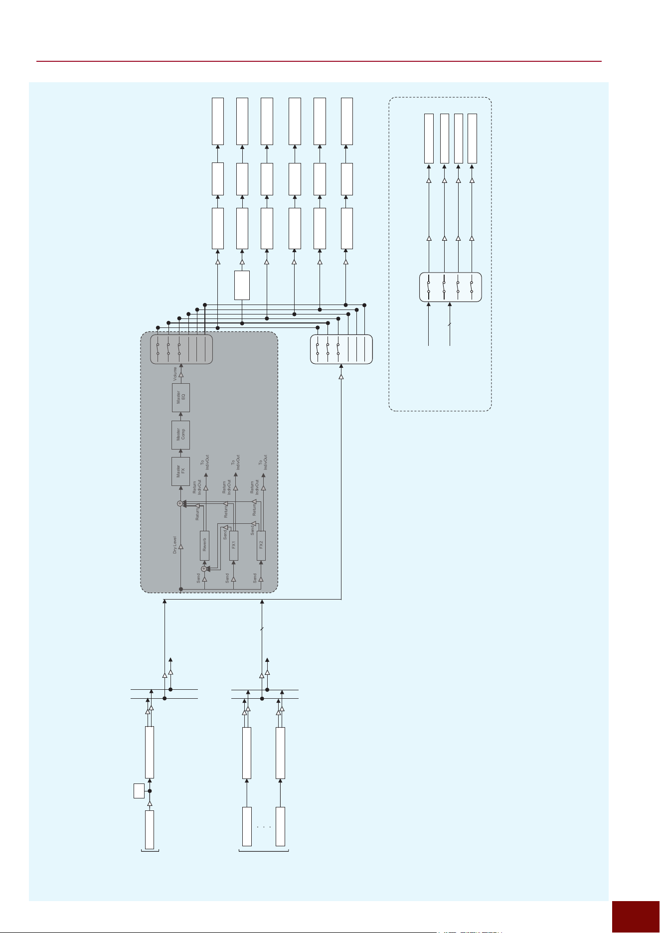
EAD50 EAD20 User Guide
228
Appendix
Block Diagram (Mic/Trigger, Effect Thru On)
Volume
Reverb
Master
FX
FX1
FX2
Master
Comp
Master
EQ
Volume
+
+
Volume
Kick~Trig10
Return
Return
Return
Return
IndivOut
Return
IndivOut
Return
IndivOut
To
IndivOut
To
IndivOut
To
IndivOut
Dry Level
Send
Send
Send
Send
Send
Volume
To
IndivOut
USB Audio Out
Volume
Volume
Volume
Volume
Kick~Trig10
From
Mic
From
Trigger
Gain
Gain
Gain
Gain
Selector
USB Audio Out 3/4
USB Audio Out 5/6
USB Audio Out 7/8
USB Audio Out 9/10
Mic Effect Block
Mic
Gain
Level
Meter
Volume
Trigger Effect Block
Trigger Effect Block
Kick
Trig10
Trigger
(Inst)
Volume
Volume
Mic
To
IndivOut
Phones
EQ
[MASTER]
Knob
Main Out
Recorder Rec
Sampling Rec
USB Audio Out 1/2
Phones Out
Looper Rec
[AUDIO/CLICK]
Knob
[MASTER]
Knob
[AUDIO/CLICK]
Knob
[MASTER]
Knob
[AUDIO/CLICK]
Knob
[MASTER]
Knob
[AUDIO/CLICK]
Knob
[MASTER]
Knob
[AUDIO/CLICK]
Knob
[MASTER]
Knob
[AUDIO/CLICK]
Knob
Gain
Gain
Gain
Gain
Gain
Gain
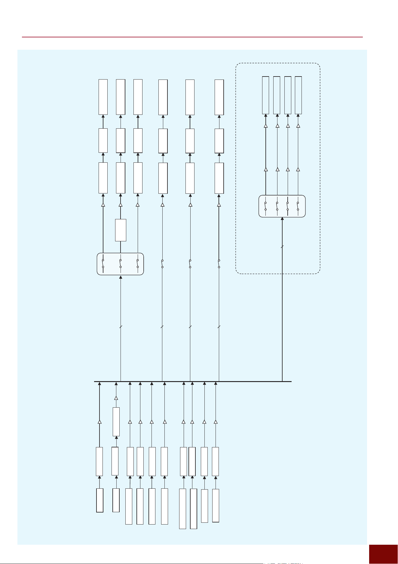
EAD50 EAD20 User Guide
229
Appendix
Aux In
Noise Gate
USB Audio In 1/2
USB Audio In 3/4
USB Audio In 5/6
USB Audio In 7/8
EQ
EQ
EQ
EQ
EQ
EQ
EQ
Recorder Playback1
Recorder Playback2
Looper Play
Click
EQ
EQ
EQ
Sampling Play
Recorder Rec
On/Off
Looper Rec
On/Off
Sampling Rec
On/Off
Click, Aux In, USB Audio In1/2~7/8,
Recorder PlayBack1~2, Looper Play, Sampling Play
Click, Aux In, USB Audio In1/2~7/8,
Recorder PlayBack1~2
Click, Aux In, USB Audio In1/2~7/8
Click, Aux In, USB Audio In1/2~7/8
Gain
Gain
Gain
Gain
Gain
Gain
Click, Aux In, USB Audio In1/2~7/8,
Recorder PlayBack1~2, Looper Play
Volume
Volume
Volume
Volume
Volume
Volume
Volume
Volume
Volume
Volume
Block Diagram (Audio Channel)
USB Audio Out
Volume
Volume
Volume
Volume
Gain
Gain
Gain
Gain
Phones
EQ
USB Audio Out 3/4
USB Audio Out 5/6
USB Audio Out 7/8
USB Audio Out 9/10
[MASTER]
Knob
Main Out
Recorder Rec
Sampling Rec
USB Audio Out 1/2
Phones Out
Looper Rec
[AUDIO/CLICK]
Knob
[MASTER]
Knob
[AUDIO/CLICK]
Knob
[MASTER]
Knob
[AUDIO/CLICK]
Knob
[MASTER]
Knob
[AUDIO/CLICK]
Knob
[MASTER]
Knob
[AUDIO/CLICK]
Knob
[MASTER]
Knob
[AUDIO/CLICK]
Knob
EAD50 EAD20 User Guide
230
Appendix
Specifications
Main Unit
EAD50 EAD20
Scene Preset: 70 or more, User: 200 Preset: 50 or more, User: 200
Tone
Generator
Mic Mic EQ 14 7
Mic Transient
Compressor
19 10
Mic Insertion Effect 1 252 252
Mic Insertion Effect 2 252 252
Trigger Tone Generator AWM2 AWM2
Maximum Polyphony 256 256
Parts 24 10
Number of Voices 2317 2203
Inst EQ 13 13
Inst Transient
Compressor
21 21
Inst Insertion Effect 252 252
Mic/Trigger Reverb 137 137
FX1 247 247
FX2 247 247
Master FX 252 252
Master Compressor 33 33
Master EQ 5 bands 5 bands
Other Click EQ 1 1
Audio EQ Recorder, Looper, Aux In,
USB Audio, Bluetooth
Recorder, Looper, Aux In,
USB Audio
Phones EQ 13 (4 bands) 13 (4 bands)
User Samples Import limit 500 User Voices, each with
10Banks
500 User Voices, each with
10Banks
Maximum loadable Sample Time Monaural: Approx. 158 minutes
(44.1 kHz, 16-bit)
Stereo: Approx. 79 minutes
(44.1 kHz, 16-bit)
Monaural: Approx. 50 minutes
(44.1 kHz, 16-bit, mono)
Stereo: Approx. 25 minutes
(44.1 kHz, 16-bit, stereo)
Sample Format WAV, AIFF WAV, AIFF
Function Integrated Trigger Input, Mic
Talk Function, Gain Auto Setup,
Crosstalk Auto Setup, Voice
Function
Mic Talk Function, Gain Auto
Setup, Crosstalk Auto Setup,
Voice Function
Click Tempo 30.0 to 300.0 BPM, tap tempo
function
30.0 to 300.0 BPM, tap tempo
function
Time Signatures 1/4 to 16/4, 1/8 to 16/8, 1/16 to
16/16
1/4 to 16/4, 1/8 to 16/8, 1/16 to
16/16
Subdivisions Accents, quarter notes, eighth
notes, sixteenth notes, eighth-
note triplets
Accents, quarter notes, eighth
notes, sixteenth notes, eighth-
note triplets
Other Per-note click parameter control
(voice, volume, pan, tuning),
wave import, timer, recorder
sync
Per-note click parameter control
(voice, volume, pan, tuning),
wave import, timer, recorder
sync
EAD50 EAD20 User Guide
231
Appendix
EAD50 EAD20
Recorder
Maximum
Recording Time
Internal Memory Approx. 90 sec Approx. 90 sec
External Memory Approx. 90 min Approx. 90 min
Maximum
Looper Time
Internal Memory Approx. 30 sec Approx. 30 sec
Maximum
Sampling Time
Internal Memory Approx. 30 sec Approx. 30 sec
Format WAV (44.1 kHz, 16-bit, stereo) WAV (44.1 kHz, 16-bit, stereo)
Function Recorder (playback × 2),
Looper, Sampling
Recorder (playback × 2),
Looper, Sampling
Live Set Users: 50 × Steps: 50 –
Panel Display Full-Dot LCD (198 × 100 dots) Full-Dot LCD (198 × 100 dots)
Controllers Modifier Knob 6 (40 assignable functions) 3 (40 assignable functions)
(not only 1/2/3 but can switch to
4/5/6)
LED Rotary Fader 5 (33 assignable functions) –
Volume Controller Slider (AUDIO, CLICK, MIC/
TRIG, OUTPUT, PHONES)
Knobs (MASTER, AUDIO/
CLICK)
Other
MUTE ALL button, Channel On/
Off button, Channel Indicator, etc.
–
Connectivity Trigger Inputs Multi Piezo (L: piezo,
R: piezo)
Trigger Inputs: q KICK/y, w
SNARE/u (standard stereo
phone jack)
Trigger Inputs: q KICK/y,
w SNARE/u, e/i, r/o
(standard stereo phone jack)
Multi Piezo (L: piezo, R:
piezo), Single Piezo (L:
piezo, R: switch), with
Attenuator
Trigger Inputs: e/i, r/o,
t/!0 (standard stereo phone
jack)
–
Single Piezo
(L: Piezo, R: Switch)
– Trigger Inputs: 5
(standard stereo phone jack)
Maximum number of
pads to be connected
10 (when Y-cable is used) 9 (when Y-cable is used)
Foot Switch FOOT SW 1, 2 (standard stereo
phone jack)
FOOT SW (standard stereo
phone jack)
Function HH Controller, Expression,
On/Off, Inc/Dec
HH Controller, Expression,
On/Off, Inc/Dec
Audio Input Mic/Line Input MIC/LINE INPUT 1, 2, 3, 4, 5
(XLR/TRS combo jack, balanced)
Phantom power (+48V) available
(only for included Sensor Unit)
Aux Input AUX IN (mini stereo phone jack) AUX IN (mini stereo phone jack)
Audio Output Main Output
OUTPUT L, R (XLR jack,
balanced)
OUTPUT L/MONO, R (standard
TS phone jack, unbalanced)
OUTPUT L/MONO, R
(standard TS phone jack,
unbalanced)
Individual Output INDIVIDUAL OUTPUT 1, 2, 3, 4,
5, 6, 7, 8 (standard TRS phone
jack, balanced)
–
Headphones PHONES (standard stereo
phone jack × 1,
mini stereo phone jack × 1)
PHONES (standard stereo
phone jack × 1,
mini stereo phone jack × 1)
MIDI MIDI OUT –
USB TO
HOST
Type USB Type-C x1 USB Type-C x1
MIDI 2 port 2 port
Audio 2 in/2 out, 24-bit, 44.1/48/96 kHz
(synchronous)
8 in/10 out, 24-bit, 44.1 kHz
(asynchronous)
2 in/2 out, 24-bit, 44.1/48/96 kHz
(synchronous)
8 in/10 out, 24-bit, 44.1 kHz
(asynchronous)
USB TO
DEVICE
Type USB Standard-A × 1 USB Standard-A × 1
MIDI USB Trigger Link (USB MIDI
Host Function)
USB Trigger Link (USB MIDI
Host Function)
External
Memory
USB Flash Drive
SD Card Supported capacity: SDHC
(max. 32 GB), SD (max. 2 GB)
–
EAD50 EAD20 User Guide
232
Appendix
EAD50 EAD20
Connectivity Bluetooth* Audio Supported profile: A2DP,
Compatible codec: SBC
–
MIDI Compliant with Bluetooth Low
Energy MIDI Specification
–
Bluetooth Version 5.0 –
Wireless Output Bluetooth Class 2 –
Radio Frequency 2.4 GHz –
Power Supply AC Adaptor PA-300C (Output: DC16 V, 2.4 A) PA-150 (Output: DC12 V, 1.5 A)
Power
Consumption
22 W (when using PA-300C AC
Adaptor)
11 W (when using PA-150 AC
Adaptor)
Standby Power Consumption 0.3 W 0.3 W
Auto Power Off
Size/Weight Dimensions (W × D × H) 394 (W) × 252 (D) × 106 (H) mm 300 (W) × 190 (D) × 70 (H) mm
Weight Main Unit Only 3.5 kg 1.4 kg
*Depending on the country in which you purchased the product, the EAD50 may not have Bluetooth capability.
Sensor Unit
EAD50 EAD20
Sensor Unit (Model) DSU50 Dedicated EAD20 Sensor Unit
Construction
Refer to the Owner’s Manual of
the DSU50.
Advanced enclosure design
improves acoustics.
Sensing
Methods
Mic High pressure-resistant mics × 2
Trigger Dedicated bass drum × 1
Connectors Sensor
outputs
For Trigger sensors A (standard phone jack)
For Mic sensors
B (standard stereo phone jack)
Size/Weight Dimensions (W × D × H) 75 (W) × 78 (D) × 88 (H) mm
Weight 450 g
Other
EAD50
EAD20
Included
Accessories
Main Unit EAD50 Quick Guide, Safety
Guide, Cubase AI download
information, AC adapter
(PA-300C or an equivalent
recommended by Yamaha)*,
Module holder,
Module holder wing bolts (× 4),
Standard stereo phone cable (× 1),
3-pin XLR cable (× 2),
Cable bands (× 3)
EAD20 Quick Guide, Safety
Guide, PA-150 (or an equivalent
recommended by Yamaha)*,
Module holder,
Module holder wing bolts (× 2),
Connector cable (× 1),
Cable ties (× 3),
Adhesive cushioning pads (× 2)
Sensor Unit DSU50 Owner’s Manual,
Stereo 5-pin XLR microphone cable,
Adhesive cushioning pads (× 2)
Separately Sold Accessories Please check the website for more information on other
available accessories (https://download.yamaha.com/)
*Depending on the country in which you purchased the product,
AC adaptor may not be included.
For Open Source Software
The firmware of this product contains open source software.
For copyright information and terms of use for each open source software, access the Yamaha website below and select your
country. Then, click on “Documents and Data” and enter the model name.
Yamaha Downloads
https://download.yamaha.com/