
WS8712
CC3551E Wi-Fi 6 Module
Data Sheet
Supports 2.4GHz & 5GHz dual-band Wi-Fi 6
Compliant with IEEE 802.11 b/g/n/ax standards
Supports: STA, softAP with up to 4 stations, Wi-Fi Direct, multi-roleAP + STA
Supports up to 8 sockets, including TCP/TCPS client, UDP unicast, UDP multicast, and UDP broadcast;
Supports one-way TCP server and TLS encryption;
Supports mDNS and DNS-SD.
Supports SNTP;
Supports HTTP/HTTPS requests, including HEAD, GET, POST, PUT, DELTET;
Supports PING;
Supports MQTT/MQTTS v3.1.1,
Module size: 19.2x18.0x2.8mm

WS8712 Datasheet
Silent Smart Technology Co., Ltd.
2
/
21
Document Information
Product Model
WS8712
Product Overview
CC3551E Wi-Fi 6 Module
Document Type
Data sheet
Document Number
Document Version
v1.3
2025.10.14
Document version update
Item
Version
number
Revisions
Revision Date
Revised by
1
v1.0
Initial version
2025.04.01
YT
2
v1.1
Modify pin definition, Chapter 3 Hardware Design
Description
2025.05.20
YT
3
v1.2
1.Modify features
2.New feature description section
2025.09.28
XT
4
v1.3
3.TCP, HTTP, MQTT support TLS encryption
2025.10.14
XT

WS8712 Datasheet
Silent Smart Technology Co., Ltd.
3
/
21
Contents
WS8712..........................................................................................................................................................................................................1
1. Product Overview .................................................................................................................................................................................... 5
1.1. Product Introduction..................................................................................................................................................................... 5
1.2. Features......................................................................................................................................................................................... 5
1.3. Application Scenario.....................................................................................................................................................................5
2. Pin Definition...........................................................................................................................................................................................6
3. Peripheral hardware design......................................................................................................................................................................8
4. Functional Description.............................................................................................................................................................................9
4.1. Wi-Fi 6 Key Technologies............................................................................................................................................................ 9
4.1.1. Multiple connections.................................................................................................................................................................9
4.1.2. Low power consumption.........................................................................................................................................................9
4.1.3. Low latency ................................................................................................................................................................................ 10
4.1.4. Improved coverage .................................................................................................................................................................10
4.2. Wi-Fi function.............................................................................................................................................................................10
4.2.1. STA and softAP ......................................................................................................................................................................... 10
4.3. SOCKET communication........................................................................................................................................................... 11
4.3.1. Host address..............................................................................................................................................................................11
4.3.2. UDP multicast............................................................................................................................................................................11
4.3.3. UDP broadcast ..........................................................................................................................................................................12
4.4. mDNS and DNS-SD................................................................................................................................................................... 12
4.5. MQTT......................................................................................................................................................................................... 13
4.5.1. MQTT Client ...............................................................................................................................................................................13
4.5.2. MQTT Broker ............................................................................................................................................................................. 13
4.5.3. Publish-Subscribe Model......................................................................................................................................................13
4.5.4. theme...........................................................................................................................................................................................13
4.5.5. QoS message quality..............................................................................................................................................................14
4.5.6. Client ID.......................................................................................................................................................................................14
4.5.7. Connect Timeout..................................................................................................................................................................... 14
4.5.8. Keep Alive ...................................................................................................................................................................................14
4.5.9. Clean Session ............................................................................................................................................................................ 15
4.5.10. Last Will .....................................................................................................................................................................................15
4.6. http.............................................................................................................................................................................................. 15
4.7. Other Features .............................................................................................................................................................................15
4.8. AT command list......................................................................................................................................................................... 15
5. Built-in device parameters .....................................................................................................................................................................18
5.1. Built-in crystal oscillator parameters..........................................................................................................................................18
5.2. Built-in Flash parameters............................................................................................................................................................18
6. Specifications.........................................................................................................................................................................................18
6.1. Limit parameters......................................................................................................................................................................... 18
6.2. RF parameter indicators..............................................................................................................................................................18
6.3. Power consumption indicators....................................................................................................................................................19
7. Package and size.................................................................................................................................................................................... 19
8. Production Guidance ..............................................................................................................................................................................20

WS8712 Datasheet
Silent Smart Technology Co., Ltd.
4
/
21
8.1. 7.1 Reflow Oven Curve .............................................................................................................................................................. 20
8.2. 7.2 Reflow temperature and time................................................................................................................................................20
9. Contact................................................................................................................................................................................................... 21

WS8712 Datasheet
Silent Smart Technology Co., Ltd.
5
/
21
1. Product Overview
1.1. Product Introduction
WS8712 is a high-performance, high-reliability dual-band Wi-Fi 6 module developed based on TI's next-generation Wi-Fi 6 chip
CC3551E. It features a powerful built-in 160MHz Arm® Cortex®-M33 processor with FPU, TrustZone®, and AI acceleration
capabilities. The module supports a maximum wireless transmit power of 17.5dBm
Functionally, the module supports IEEE 802.11 b/g/n/ax standards, Wi-Fi 6 operating in both the 2.4GHz and 5GHz bands, Key
features of this module include a complete software development kit with open-source TCP/IP and TLS stacks, support for a 3-wire
PTA coexistence architecture for use with external 2.4GHz radios (such as Thread or Zigbee®), STA support, softAP with up to four
stations, Wi-Fi Direct, and multi-role AP + STA functionality, fully satisfying diverse applications.
1.2. Features
Features
Supports 2.4GHz & 5GHz dual-band Wi-Fi 6
Compliant with IEEE 802.11 b/g/n/ax standards
Supports multi-role AP + STA
Achieve up to 17.5dBm output power
Receive sensitivity – 98.6dBm@1 Mbps DSSS
Supports up to 8 sockets, including TCP/TCPS client, UDP unicast, UDP multicast, and UDP broadcast;
Support one TCP server and TLS encryption;
Supports mDNS and DNS-SD.
Support HTTP/HTTPS requests, including HEAD, GET, POST, PUT, DELTET;
Supports SNTP;
Supports PING;
Supports MQTT/MQTTS v3.1.1
Supports -40~85℃ operating temperature
Module size: 19.2x18.0x2.8mm
1.3. Application Scenario
Application Scenario
Building automation (thermostats, wireless security cameras, video doorbells, garage door systems)
Medical wearables (infusion pumps, multi-parameter patient monitors, telehealth systems)
Smart appliances (refrigerators, ovens, washing machines, air conditioners, mowing robots)
Three meters, power grid infrastructure, factory automation and control
Asset Tracking

WS8712 Datasheet
Silent Smart Technology Co., Ltd.
6
/
21
2. Pin Definition
Pin
number
Pin Name
Pin
Type
Pin Purpose
1
GND
P
Ground wire, connected to the power reference ground
2
VDD
P
Power supply positive reference, voltage range 3V to 3.6V, recommended 3.3V@1A
3
EN
I
Module enable reset pin, low level reset module, built-in 10K pull-up;
4
GPIO35
I/O
General IO port
5
GPIO34
I/O
General IO port
6
GPIO33
I/O
General IO port
7
GPIO32
I/O
General IO port
8
GPIO31
I/O
General IO port
9
GPIO30
I/O
General IO port
10
LOGGER
O
Logger output
11
GPIO29
I/O
General IO port
12
GPIO28
I/O
General IO port
13
GPIO27
I/O
General IO port
14
GPIO26
I/O
General IO port
15
GPIO19
I/O
General IO port
16
GPIO18
I/O
General IO port
17
GPIO17
I/O
General IO port
18
GPIO16
I/O
General IO port
19
NC
-
No Connect
20
NC
-
No Connect

WS8712 Datasheet
Silent Smart Technology Co., Ltd.
7
/
21
21
SWCLK
O
SWD debug clock interface
22
SWDIO
I/O
SWD debugging data interface
23
GPIO04
I/O
General IO port
24
GPIO03
I/O
General IO port
25
NC
-
No Connect
26
NC
-
No Connect
27
GPIO37
I/O
General IO port
28
GPIO14
I/O
General IO port
29
GPIO13
I/O
General IO port
30
GPIO12
I/O
General IO port
31
GPIO11
I/O
General IO port
32
LFXT_N
I/O
External 32.768KHz low-speed clock interface N
33
LFXT_P
I/O
External 32.768KHz low-speed clock external interface P
34
GPIO10
I/O
General IO port
35
GPIO15
I/O
General IO port
36
UART1_RX
I
UART data reception (can be connected to XDS110 for debugging)
37
UART1_TX
O
UART data transmission (can be connected to XDS110 for debugging)
38
GPIO2
I/O
General IO port
39
GPIO36
I/O
General IO port
40
GND
P
Ground wire, connected to the power reference ground
Note: 1. For detailed multiplexing functions of general-purpose I/O, refer to the CC3551E official manual provided by TI for settings;
2、The module GPIO uses a 3.3V voltage domain by default, and a 1.8V version can be customized;
3、Unused GPIO can be left floating;
WS8712 Datasheet
Silent Smart Technology Co., Ltd.
8
/
21
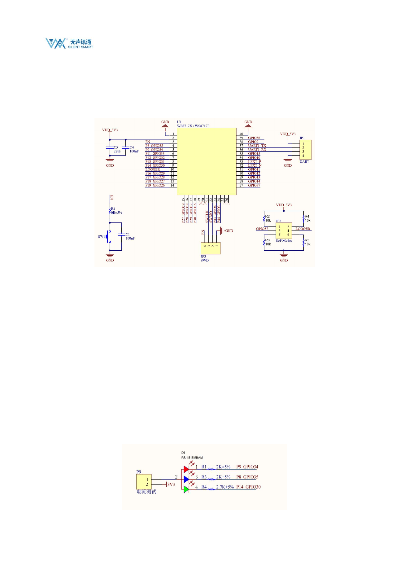
3. Peripheral hardware design
Application circuit diagram of the module connected to peripheral devices (such as power supply, antenna, reset button, SWD
interface, UART interface , etc.) .
The EPAD on the bottom of the module can be soldered to the baseplate without soldering it. Soldering to the baseplate provides
better heat dissipation. If you wish to solder the EPAD to the baseplate, ensure that you use an appropriate amount of solder paste.
Avoid excessive solder paste, which can increase the distance between the module and the baseplate and affect the fit between
the pins and the baseplate.
The figure above is a partial diagram of the recommended peripheral circuit based on WS8712. The detailed recommended
circuit includes components such as SD card interface, buttons, LED indicators, USB to TTL converter, etc. For high-definition
files, please see the "CC35X1_EVB_Sch.pdf" file in the sales materials;
To ensure stable operation of the module, the module power supply must be between 3V and 3.6V, with 3.3V recommended. It is
recommended to use an external LDO or DC-DC power supply with a power supply capacity greater than 800mA.
The module pin level defaults to 3.3V, and supports customized 1.8V versions;
Pins 30 and 31 of the module are UART1_RX and UART1_TX respectively. When the module is connected to XDS110 for
debugging, these pins together with SWCLK, SWDIO, and RESET form the debugging interface.
For details about the control and debugging information output of SOP, see the CC3551E chip manual. It is recommended to lead
out the GPIO37 pull-up and LOGGER pins.
The recommended circuit provides an RGB LED for test indication. The detailed interface is as follows:
WS8712 Datasheet
Silent Smart Technology Co., Ltd.
9
/
21
Pin GPIO34 controls the red LED, GPIO35 controls the blue LED, and GPIO30 controls the green LED;
P9 is the power supply for the LED. If the LED is not in use, it can be disconnected to avoid affecting the working status of the
pin.
4. Functional Description
4.1. Wi-Fi 6 Key Technologies
This only describes the Wi-Fi 6 technology itself, and does not mean that the current module supports all Wi-Fi 6 features.
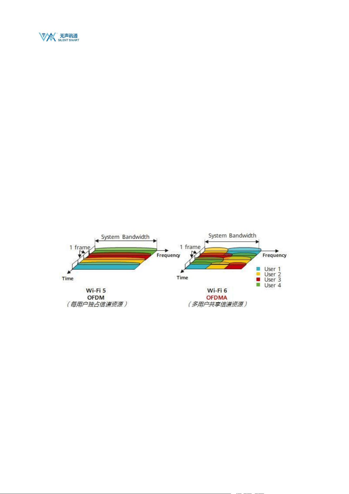
4.1.1. Multiple connections
Before Wi-Fi 6, data transmission utilized the OFDM mode, where users were distinguished by different time segments. In each time
segment, one user exclusively occupied all channel resources and transmitted a complete data packet.
Wi-Fi 6 introduces a more efficient data transmission mode called OFDMA (also known as MU-OFDMA because it supports
multi-user uplink and downlink). This mode allocates subcarriers to different users and adds multiple access to OFDM systems to
achieve multi-user channel resource reuse. As a result, Wi-Fi 5 increases the number of connections by 4-8 times compared to Wi-Fi 4.
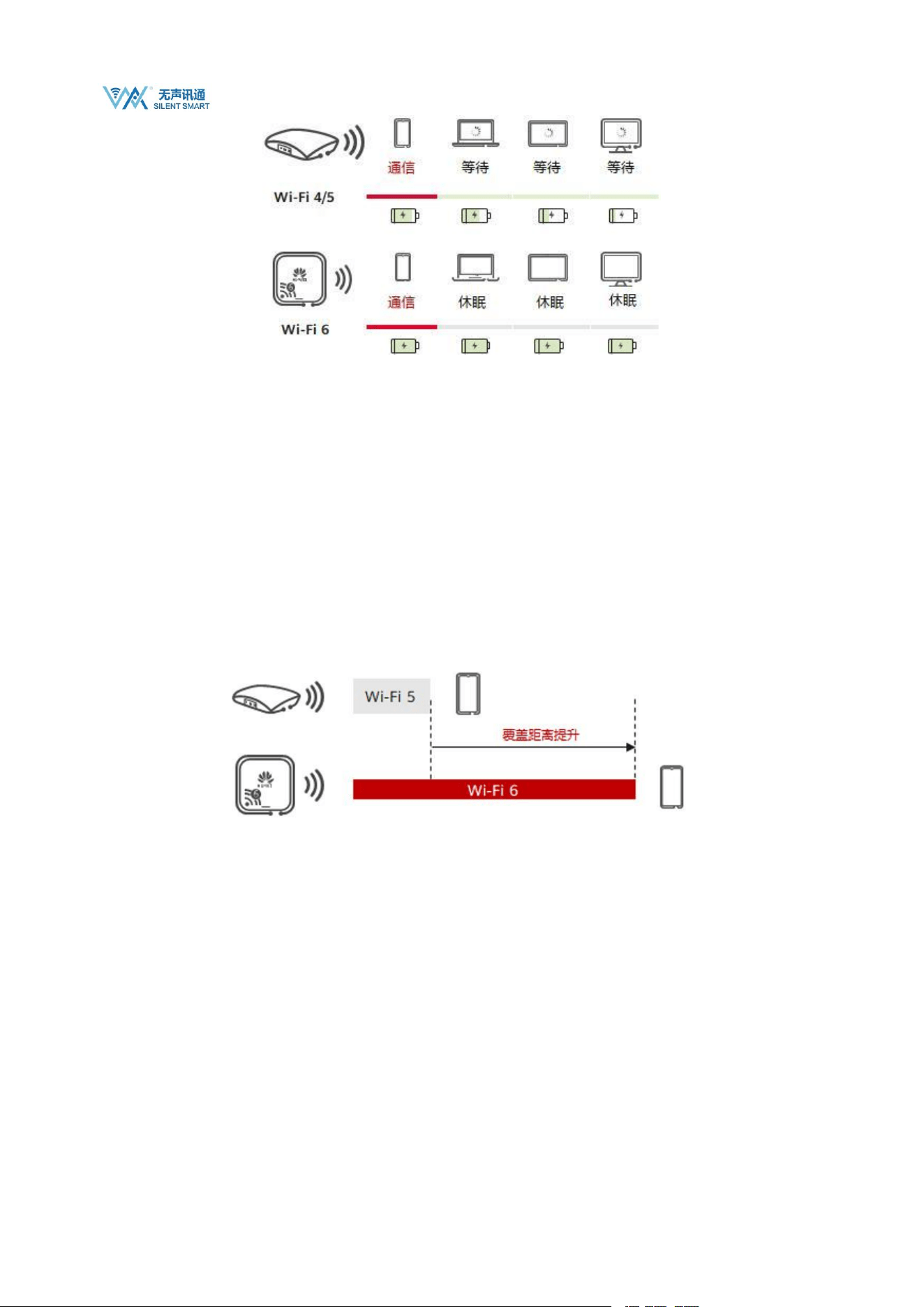
4.1.2. Low power consumption
Target Wake Time (TWT) is another crucial resource scheduling feature supported by 802.11ax, drawing inspiration from the 802.11ah
standard. It allows devices to negotiate when and how frequently they will wake up to send or receive data. Furthermore, the Wi-Fi
Access Point (AP) can group client devices into different TWT cycles, thereby reducing the number of devices simultaneously
competing for the wireless medium after waking up. TWT also extends the sleep time for devices, significantly improving battery life
for battery-powered terminals.
WS8712 Datasheet
Silent Smart Technology Co., Ltd.
10
/
21
4.1.3. Low latency
By using OFDMA technology, IoT devices can quickly access unoccupied RU frequency domain resources to ensure instant
communication.
4.1.4. Improved coverage
Since the Wi-Fi 6 standard uses the Long OFDM Symbol transmission mechanism, the duration of each data transmission is increased
from the original 3.2μs to 12.8μs. The longer transmission time can reduce the terminal packet loss rate; in addition, Wi-Fi 6 can use a
minimum bandwidth of 2MHz for narrowband transmission, effectively reducing frequency band noise interference, improving
terminal reception sensitivity, and increasing coverage distance.
4.2. Wi-Fi function
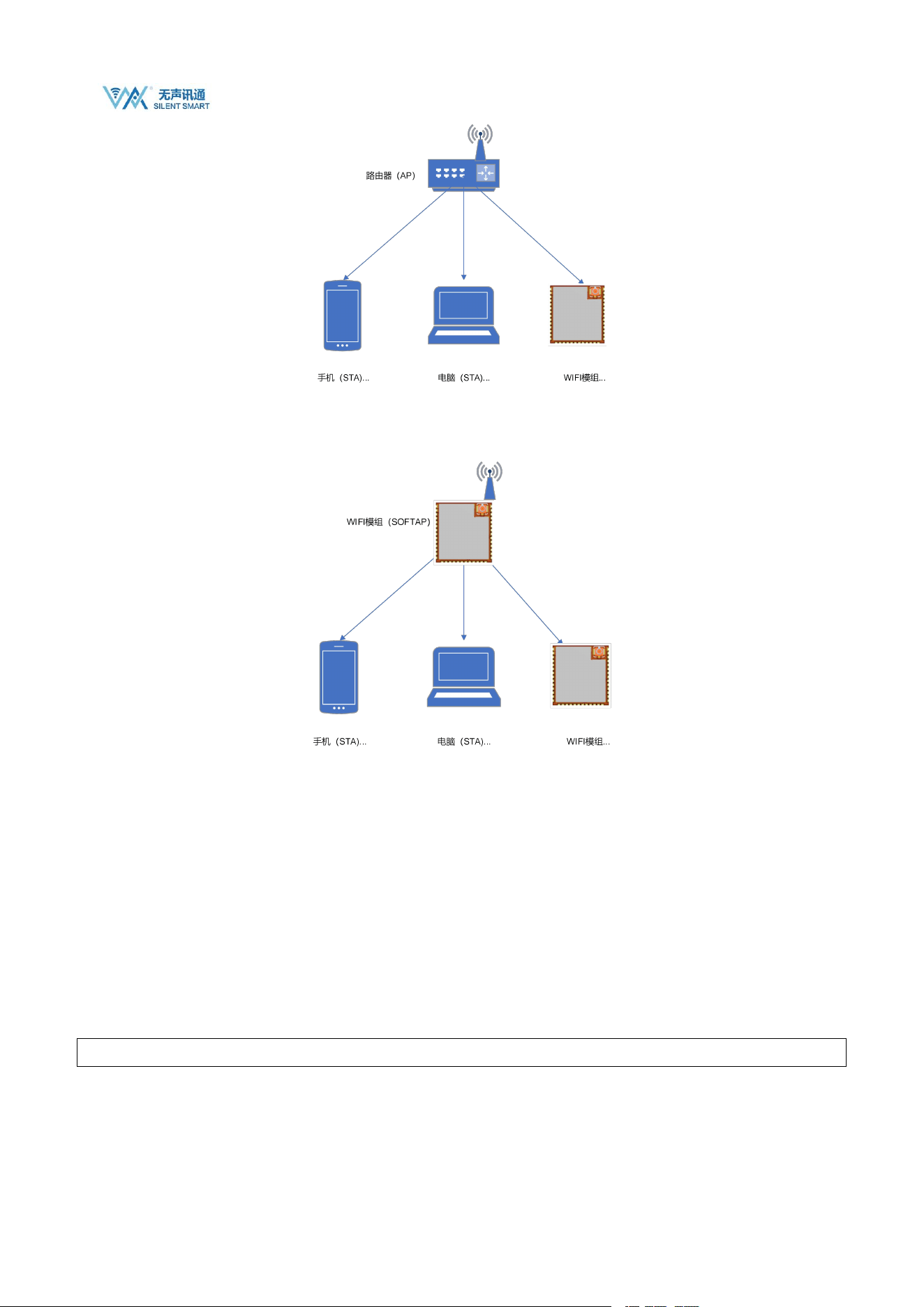
4.2.1. STA and softAP
The WS8712 module supports two Wi-Fi modes: STA, SOFTAP, and STA+SOFTAP.
STA site, each terminal connected to the wireless network (such as laptops, PDAs and other user devices that can be connected to the
Internet) can be called a site.
WS8712 Datasheet
Silent Smart Technology Co., Ltd.
11
/
21
AP
(
access point
)
is the creator of a wireless network and the central node of the network. A typical wireless router used in a home or
office is an AP.
Notice:
1. The Wi-Fi module must be configured in Wi-Fi mode before use.
4.3. SOCKET communication
The module provides up to 8 socket links, including TCP client, UDP unicast, UDP multicast, and UDP broadcast. It also supports a
TCP server. When used as a TCP server, it can only accept a maximum of 8 connections.
4.3.1. Host address
When using AT commands to establish a link, you need to specify the remote IP or domain name. Because the module supports full
mDNS and DNS-SD features, the host address can be filled in with the mDNS host name.
Here is an example:
AT+CIPSTART="TCP","tts.local.",3456
4.3.2. UDP multicast
UDP multicast, also known as UDP multicast, is a network communication technology that allows a single data packet to be sent to

WS8712 Datasheet
Silent Smart Technology Co., Ltd.
12
/
21
multiple destinations. In multicast, packets are sent to a multicast address, which represents a group of devices rather than a single
device. This communication method is very effective when information needs to be sent to multiple recipients simultaneously .
In IPv4, multicast addresses range from 224.0.0.0 to 239.255.255.255. These addresses are divided into different categories, including
link-local multicast addresses, reserved multicast addresses, and administrative multicast addresses. For example, addresses 224.0.0.0
to 224.0.0.255 are link-local multicast addresses that can only be used within a local area network, while addresses 239.0.0.0 to
239.255.255.255 are locally administered multicast addresses that are valid only within a specific local scope .
To implement multicast communication, the sender needs to send data to a fixed multicast address and port. The receiver needs to bind
to the corresponding port and join the multicast group. In this way, the receiver can receive the data sent to the multicast address.
4.3.3. UDP broadcast
Broadcast is used to send data to all hosts on the same network. The broadcast address is typically an IP address where all host bits in
the subnet are set to 1.
For example:
When the IP address is 192.168.1.0 with a subnet mask of 255.255.255.0, the broadcast address becomes 192.168.1.255. Broadcasts
are confined to the local area network, and routers do not forward broadcast packets
4.4. mDNS and DNS-SD
In a local area network, devices need to know each other's IP addresses before they can communicate with each other. In most cases,
the IP addresses of devices are not static IP addresses, but are dynamically assigned IP addresses through the DHCP protocol. In order
to communicate, the IP addresses of other devices must be known.
If the IP address is unknown, a device cannot communicate directly with the target within the local area network.The role of mDNS is
to solve this problem. mDNS can get the IP address of the target host through the name like DNS, but the name must end with .local
Every host that enters the LAN and has the mDNS service enabled will multicast a message containing its own name and IP address to
all hosts in the LAN. Other hosts that also have the service will respond by also sending their own name and IP address。
The module provides complete mDNS records, but only supports A record queries. For example:
We start an mDNS service: localhost is "ws8712 " , service name: " _http._tcp.local. ", service port is 80, and no text information is
set.
Then its mDNS record is as follows:
Record
Category
Record content
Remark
A
ws8712.local. maps to 192.168.1.120
The correspondence between host names and IPv4
SRV
ws8712._http._tcp.local. is mapped to ws8712.local., port 80
Identifies the host name and port number that the
service instance name corresponds to
PTR
_http._tcp.local. maps to ws8712._http._tcp.local
Identifies the correspondence between the service
instance name and the service type
TXT
Additional information provided by the service

WS8712 Datasheet
Silent Smart Technology Co., Ltd.
13
/
21
instance , given as key-value pairs
The module AT command only provides two query commands:
AT+MDNSQUERY queries PRT records
AT+MDNSQUERY="_http._tcp.local."
+MDNSQUERY="192.168.1.111","ws8712","_http._tcp.local.",80,"test=1","other=value"
+MDNSQUERY="192.168.1.11 2 ","test","_http._tcp.local.",80,"test=1","other=value"
+OK
AT+TGOTIP can query Class A record
AT+TGOTIP="ws8712.local"
+TGOTIP=192.168.1.111
All network functions of the module that require remote addresses can resolve mDNS addresses.
4.5. MQTT
MQTT (Message Queuing Telemetry Transport) is a lightweight, publish-subscribe messaging protocol suitable for
resource-constrained devices and low-bandwidth, high-latency, or unstable network environments. It is popular in IoT applications,
enabling efficient communication between sensors, actuators, and other devices.
4.5.1. MQTT Client
Any application or device that runs the MQTT client library is an MQTT client. For example, the WS8712 module, instant messaging
applications using MQTT are clients, various sensors that use MQTT to report data are clients, and various MQTT Testing tools are
also clients.
4.5.2. MQTT Broker
The MQTT Broker is a key component responsible for handling client requests, including establishing and disconnecting connections,
subscribing, and unsubscribing. It also forwards messages. An efficient and robust MQTT Broker can easily handle massive
connections and millions of message throughput, helping IoT service providers focus on business development and quickly build
reliable MQTT applications.
4.5.3. Publish-Subscribe Model
The publish-subscribe model differs from the client-server model in that it decouples the clients that send messages (publishers) from
the clients that receive messages (subscribers). Publishers and subscribers don't need to establish a direct connection; instead, the
MQTT broker handles message routing and distribution .
4.5.4. theme
The MQTT protocol forwards messages based on topics. Topics are differentiated by /, similar to URL paths, for example:
chat/room/1
sensor/10/temperature

WS8712 Datasheet
Silent Smart Technology Co., Ltd.
14
/
21
sensor/+/temperature
MQTT topics support the following two wildcard characters: + and #.
+: represents a single-level wildcard, for example, a/+ matches a/x or a/y.
#: Indicates multiple layers of wildcards. For example, a/# matches a/x, a/b/c/d.
Note: Wildcard topics can only be used for subscriptions, not for publishing.
For more details about MQTT topics, please refer to "MQTT Version 3.1.1 4.7 Topic Names and Topic Filters ".
4.5.5. QoS message quality
MQTT provides three qualities of service (QoS) to ensure message reliability in different network environments.
QoS 0: Messages are delivered at most once. If the client is unavailable, it will lose the message.
QoS 1: Messages are delivered at least once.
QoS 2: Messages are delivered only once.
For more details about MQTT QoS, please refer to "MQTT Version 3.1.1 4.3 Quality of Service levels and protocol flows ".
4.5.6. Client ID
The MQTT server uses the Client ID to identify the client. Each client connected to the server must have a unique Client ID. The
Client ID is usually a UTF-8 string of 1 to 23 bytes.
If a client uses a duplicate Client ID to connect to the server, the client that has successfully connected using the Client ID will be
kicked offline.
Username & Password
The MQTT protocol can use usernames and passwords for authentication and authorization, but if this information is not encrypted,
the username and password will be transmitted in plain text. If username and password authentication is set, it is best to use the
MQTTs or WSS protocols.
Most MQTT servers use anonymous authentication by default. In anonymous authentication, just set the username and password to
empty strings.
4.5.7. Connect Timeout
Connection timeout duration, the waiting time before receiving the connection confirmation from the server. If no connection
confirmation is received within the waiting time, the connection fails.
4.5.8. Keep Alive
Keep Alive period is a time interval in seconds. When the client has no message to send, it will periodically send heartbeat messages to
the server according to the value set by Keep Alive to ensure that the connection is not disconnected by the server.
After the connection is successfully established, if the server does not receive any packets from the client within 1.5 times the Keep
Alive time, it will be considered that there is a problem with the connection with the client, and the server will disconnect the client.

WS8712 Datasheet
Silent Smart Technology Co., Ltd.
15
/
21
4.5.9. Clean Session
When false, it means creating a persistent session. When the client disconnects, the session will still be maintained and offline
messages will be saved until the session times out. When true, it means creating a new temporary session. When the client disconnects,
the session will be automatically destroyed.
Persistent sessions prevent message loss after a client reconnects and eliminate the overhead of repeated subscriptions after the client
reconnects. This feature is very useful in IoT scenarios with low bandwidth and unstable networks.
The number of messages the server saves for persistent sessions depends on the server configuration. For example, the free public
MQTT server provided by EMQ sets the offline message retention time to 5 minutes, the maximum number of messages to 1,000, and
does not save QoS 0 messages.
Note: The premise of persistent session recovery is that the client uses a fixed Client ID to connect again. If the Client ID is dynamic, a
new persistent session will be created after the connection is successful.
4.5.10. Last Will
The Last Will is a mechanism in MQTT that allows a client to gracefully notify other clients in the event of its unexpected
disconnection.When an MQTT client with a will message configured goes offline unexpectedly, the MQTT server will publish the will
message configured by the client.
Unexpected disconnections include: the connection is closed by the server due to network failure; the device loses power unexpectedly;
the device attempts to perform an unauthorized operation and the server closes the connection, etc.
The will message can be regarded as a simplified version of the MQTT message, which also contains Topic, Payload, QoS, Retain and
other information.
When the device is accidentally disconnected, the will message will be sent to the will topic;
Will Payload is the content of the message to be sent;
The QoS of the will is consistent with the QoS of ordinary MQTT messages.
When Will Retain is true, the will message is a retained message. The MQTT server stores the latest retained
message for each topic so that clients that come online after the message is published can still receive the message
when they subscribe to the topic.
4.6. http
The module supports http1.1 and provides five request types: head, get, post, put and delete.
Users can add request headers to http requests according to their needs.
4.7. Other Features
The module supports the ping command and the sntp function. Ping can be used to determine whether the link with the remote host is
connected. Sntp can be used to obtain the network time.
In addition, the module provides an iperf speed measurement function, but unfortunately, the iperf function is not complete and the
actual throughput of the module cannot be tested through this test.
4.8. AT command list
Send AT command: AT+HELP to get the supported command list

WS8712 Datasheet
Silent Smart Technology Co., Ltd.
16
/
21
AT commands
Execute
Command
Query
Command
Setting
Commands
Help
Command
Functional Description
AT+ECHO
×
√
√
√
Echo function switch
AT+GMR
×
√
×
√
Get module information
AT+HELP
√
×
√
×
Get the list of AT commands supported by the
module
AT+NTPSVR
×
√
√
√
Set or get NTP server
AT+RST
√
×
×
×
Restart
AT+SLEEP
√
×
×
×
Hibernation
AT+SYSTIMESTAMP
×
√
×
×
Get network time
AT+UART
×
√
√
√
Set or query UART parameters
AT+CIPAP
×
√
√
√
Get or set SOFTAP IP
AT+CIPAPMAC
×
√
√
√
Get or set the MAC address of the SOFTAP
AT+CIPSTA
×
√
√
√
Get or set the STA's IP address
AT+CIPSTAMAC
×
√
√
√
Get or set the MAC address of a STA
AT+CWDHCP
×
√
√
√
DHCP enabled or disabled
AT+CWJAP
×
×
√
√
Connect to AP
AT+CWLAP
√
×
√
√
Scan for nearby APs
AT+CWLIF
×
√
×
√
Obtaining STA Information
AT+CWMODE
×
√
√
√
Set or get the module's Wi-Fi role
AT+CWQAP
√
×
×
√
Disconnect from Wi-Fi
AT+CWQIF
×
×
√
√
Disconnect the station from the SoftAP
AT+CWSAP
×
√
√
√
Create SoftAP
AT+MDNS
×
√
√
√
Start or stop the mDNS service
AT+MDNSQUERY
×
×
√
√
Querying the mDNS service
AT+CIPCLOSE
√
×
√
√
Disconnecting a TCP connection
AT+CIPMUX
×
√
√
√
Set or get TCP multiple connections
AT+CIPSEND
√
×
√
√
Sending Data
AT+CIPSERVER
×
√
√
√
Create or close a TCP service
AT+CIPSTART
×
×
√
√
Creating TCP and UDP connections
AT+IPERFRUN
×
×
√
√
iperf start
AT+IPERFSTOP
√
×
×
×
iperfstop
AT+PING
×
×
√
√
ping
AT+HTTPCHEAD
×
√
√
√
Set or get HTTP request header
AT+HTTPCLIENT
×
×
√
√
Sending HTTP requests
AT+HTTPCPOST
×
×
√
√
POST data of specified length
AT+HTTPCPUT
×
×
√
√
PUT data of specified length
AT+HTTPGETSIZE
×
×
√
√
Get the size of HTTP resources
AT+HTTPURLCFG
×
√
√
√
Set or get the HTTP long URL
AT+MQTTCLEAN
×
×
√
×
Disconnect MQTT
AT+MQTTCONN
×
√
√
√
Connecting to an MQTT Broker
AT+MQTTCONNCFG
×
√
√
√
Set or get MQTT connection parameters

WS8712 Datasheet
Silent Smart Technology Co., Ltd.
17
/
21
AT+MQTTPUBRAW
×
×
√
√
Publishing MQTT messages
AT+MQTTSUB
×
×
√
√
Subscribe to a topic
AT+MQTTUNSUB
×
×
√
√
Unsubscribe
AT+MQTTUSERCFG
×
√
√
√
Set or get MQTT user parameters
AT+TGOTIP
×
×
√
×
Get the domain name or mDNS host IP
× : Not supported; √ : Supported

WS8712 Datasheet
Silent Smart Technology Co., Ltd.
18
/
21
5. Built-in device parameters
5.1. Built-in crystal oscillator parameters
Frequency
Parameter
52MHz
10ppm, 9pF, -40°C to +85°C
32.768KHz
20ppm, 7pF, -40°C to +125°C
5.2. Built-in Flash parameters
The module has a built-in 32M-Bit Flash. The connection pins between CC3551E and FLASH are as follows:
Flash pin
CC3551E Pinout
SCK
xSPI_CLK (GPIO24), 21 pins
D0
xSPI_D0 (GPIO25), pin 20
D1
xSPI_D 1 (GPIO21), 25-pin
D2
xSPI_D 2 (GPIO22), 24-pin
D3
xSPI_D 3 (GPIO23), 22 pins
CS
xSPI_ CS (GPIO20), 60-pin
6. Specifications
6.1. Limit parameters
Main parameters
Performance
Remark
Minimum
Maximum
Power supply voltage (V)
-0.5
4.2
Over 4.2V will permanently burn the module
I/O voltage (V)
-0.5
3.6V
Over 3.6V will permanently burn the module
Blocking power (dBm)
-
10
The probability of burning is lower when used at close range
Operating temperature (°C)
-40
+85
Support customized 105℃ version
Storage temperature (℃)
-40
+85
-
6.2. RF parameter indicators
Main parameters
Performance
Remark
Minimum
Typical
values
Maximum
Operating voltage (V)
3
3.3
3.6
Recommended 3.3V power supply
Communication level (V)
3.3
The default interface voltage is 3.3V, and can be
customized to 1.8V
Operating frequency band (Hz)
2.412G
2.442G
2.472G
Support 2.4G frequency band
5.180G
5.550G
5.845G
Support 5G frequency bands
WS8712 Datasheet
Silent Smart Technology Co., Ltd.
19
/
21
RF
Performa
nce
Transmitting power
(dBm)
-
17.5
-
1 Mbps DSSS @2.4-GHz
-
16
-
54 Mbps OFDM @2.4-GHz
-
16
-
6 Mbps OFDM @5-GHz
-
14
54 Mbps OFDM @5-GHz
Receiving sensitivity
(dBm)
-
-98
-
1 Mbps DSSS @2.4-GHz
-
-92.2
6 Mbps OFDM @5-GHz
-
-75.5
-
54 Mbps OFDM @2.4-GHz
RF interface
-
IPEX
-
First generation IPEX interface, 50Ω characteristic
impedance
Note: For more parameter indicators, please refer to the CC3551E chip manual. The module performance indicators can be consistent
with those of the chip.
6.3. Power consumption indicators
Main parameters
Performance
Remark
Minimum
Typical values
Maximum
Transmitting current (mA) @3.3V
-
390
560
6 OFDM @2.4-GHz
-
360
430
6 OFDM@5-GHz
Receiving current (mA) @3.3V
-
68
-
@2.4-GHz
-
115
-
@5-GHz
Note: For more parameter indicators, please refer to the CC3551E chip manual. The module performance indicators can be consistent
with those of the chip.
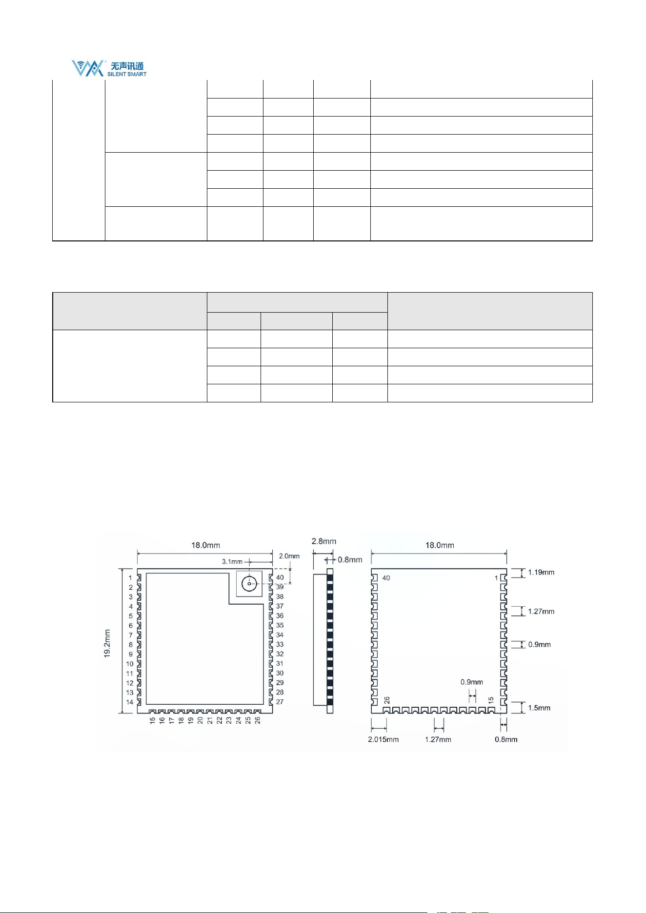
7. Package and size
Module size: 19.2x18.0x2.8mm stamp hole interface;
Antenna interface: first generation IPEX, characteristic impedance 50Ω;
The back of the module contains EPAD detailed size parameters. Please refer to the Lib package library provided in the sales
materials.
WS8712 Datasheet
Silent Smart Technology Co., Ltd.
20
/
21
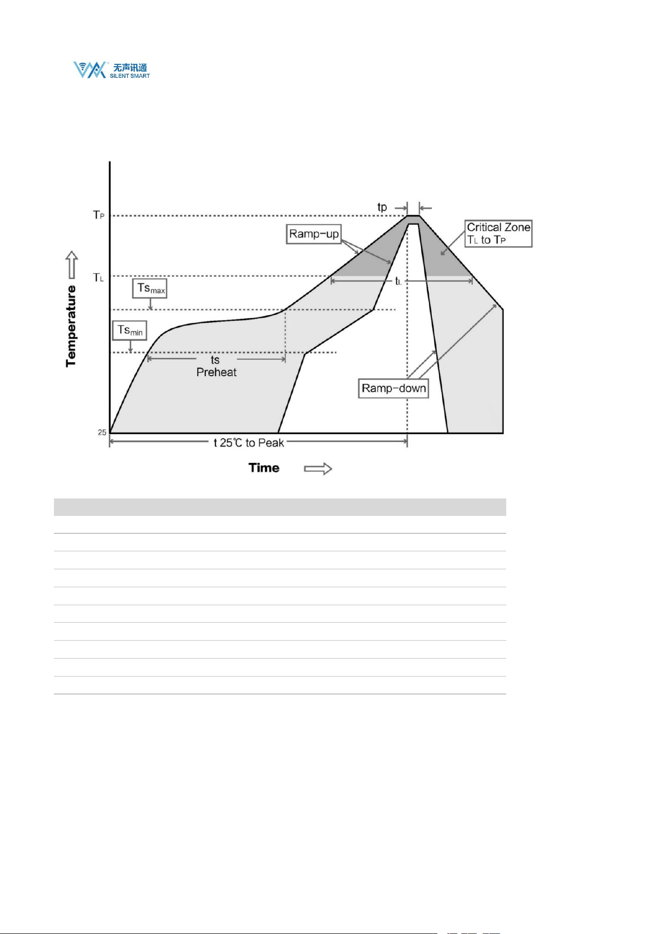
8. Production Guidance
8.1. 7.1 Reflow Oven Curve
8.2. 7.2 Reflow temperature and time
Profile Feature
Sn-Pb Assembly
Pb-Free Assembly
Solder Paste
Sn63/Pb37
Sn96.5/Ag3/Cu0.5
Preheat Temperature min (Tsmin)
100 ℃
150 ℃
Preheat temperature max (Tsmax)
150 ℃
200 ℃
Preheat Time (Tsmin to Tsmax)(ts)
60-120 seconds
60-120 seconds
Average ramp-up rate(Tsmax to Tp)
3 ℃ /second max
3 ℃ /second max
Liquidous Temperature (TL)
183 ℃
217 ℃
Time(tL)Maintained Above(TL)
60-90 seconds
30-90 seconds
Peak temperature (Tp)
220-235 ℃
230-250 ℃
Aveage ramp-down rate(Tp to Tsmax)
6 ℃ /second max
6 ℃ /second max
Time 25 ℃ to peak temperature
6 minutes max
8 minutes max

WS8712 Datasheet
Silent Smart Technology Co., Ltd.
21
/
21
9. Contact
Contact
Tell
E-Mail
Mr Chen
+86 15000319232
Tel: 028-64823553
Address: Room 303-7, 3rd Floor, Building 12, IP Technology Center, Xingsheng West Road, Jinniu District, Chengdu, China

FCC Caution.
This device complies with part 15 of the FCC Rules. Operation is subject to the following two
conditions:
(1) This device may not cause harmful interference, and
(2) this device must accept any interference received, including interference that may cause
undesired operation.
Any Changes or modifications not expressly approved by the party responsible for compliance
could void the user's authority to operate the equipment.
Note: This equipment has been tested and found to comply with the limits for a Class B digital
device, pursuant to part 15 of the FCC Rules. These limits are designed to provide reasonable
protection against harmful interference in a residential installation. This equipment generates
uses and can radiate radio frequency energy and, if not installed and used in accordance with the
instructions, may cause harmful interference to radio communications. However, there is no
guarantee that interference will not occur in a particular installation. If this equipment does
cause harmful interference to radio or television reception, which can be determined by turning
the equipment off and on, the user is encouraged to try to correct the interference by one or
more of the following measures:
-Reorient or relocate the receiving antenna.
-Increase the separation between the equipment and receiver.
-Connect the equipment into an outlet on a circuit different from that to which the receiver is
connected.
-Consult the dealer or an experienced radio/TV technician for help.
FCC Radiation Exposure Statement:
This equipment complies with FCC radiation exposure limits set forth for an uncontrolled
environment. This equipment should be installed and operated with minimum distance 20 cm
between the radiator & your body.

KDB 996369 D03 statements
2.2 List of applicable FCC rules:
The module complies with FCC Part 15.247& FCC Part 15.407.
FCC ID: 2BB8U-WS8712 on User manual and on the external of the packaging.
2.3 Summarize the specific operational use conditions
The module has been certified for Potable applications. This transmitter must not beco-located or
operating in conjunction with any other antenna or transmitter
2.4 Limited module procedures
The module is not a limited module.
2.5 Trace antenna designs
Not applicable
2.6 RF exposure considerations
This equipment complies with FCC’s RF radiation exposure limits set forth for an
uncontrolled environment. The antenna(s) used for this transmitter must not be collocated or operating
in conjunction with any other antenna or transmitter.
2.7 Antennas
The EUT use a permanently attached antenna which is unique.
2.8 Label and compliance information
The host system using this module, should have label in a visible area indicated the
following texts: “Contains FCC ID: 2BB8U-WS8712
2.9 Information on test modes and additional testing requirements
When testing host product, the host manufacture should follow FCC KDB Publication 996369 D04
Module Integration Guide for testing the host products. The host manufacturer may operate their
product during the measurements. In setting up the configurations, if the pairing and call box options
for testing does not work, then the host product manufacturer should coordinate with the module
manufacturer for access to test mode software.
The module has been certified for Potable applications. This transmitter must not be co-located or
operating in conjunction with any other antenna or transmitter
2.10 Additional testing, Part 15 Subpart B disclaimer
The module without unintentional-radiator digital circuity, so the module does not
require an evaluation by FCC Part 15 Subpart B. The host shoule be evaluated by the FCC Subpart B.
2.11 Note EMI Considerations
host manufacture is recommended to use D04 Module Integration Guide recommending as
"best practice" RF design engineering testing and evaluation in case non-linear interactions generate
additional non-compliant limits due to module placement to host components or properties
2.12 How to make changes
This module is stand-alone modular. If the end product will involve the Multiple simultaneously
transmitting condition or different operational conditions for a stand-alone modular transmitter in
evaluation (i.e., no C2PC required when no emission exceeds the limit of any individual device
(including unintentional radiators) as a composite. The host manufacturer must fix any failure
a host, host manufacturer have to consult with module manufacturer for the installation method in end
system. According to the KDB 996369 D02 Q&A Q12, that a host manufacture only needs to do
anevaluation (i.e., no C2PC required when no emission exceeds the limit of any individual device(including
unintentional radiators) as a composite. The host manufacturer must fix any failure