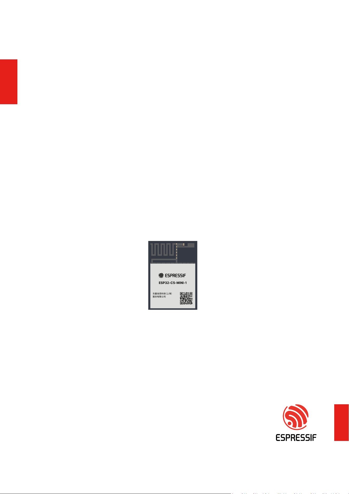
ESP32-C5-MINI-1
User Manual Version 1.0
Module that supports 2.4 and 5 GHz dual-band Wi-Fi 6 (802.11ax), Bluetooth
®
5 (LE),
Zigbee, and Thread (802.15.4)
Built around ESP32-C5 series of SoCs, 32-bit RISC-V single-core microprocessor
Flash up to 4 MB
22 GPIOs, rich set of peripherals
On-board PCB antenna
ESP32-C5-MINI-1
.espressif.com

1 Module Overview
1 Module Overview
1.1 Features
CPU and On-Chip Memory
• ESP32-C5 embedded, 32-bit RISC-V
single-core microprocessor, up to 240 MHz
• ROM: 320 KB
• HP SRAM: 384 KB
• LP SRAM: 16 KB
Wi-Fi
• 1T1R in 2.4 and 5 GHz dual band
• Operating frequency: 2412 ~ 2462 MHz, 5150 ~
5850 MHz
• Max output power �16dBm for 2.4G; 19 dBm for
5G
• IEEE 802.11ax-compliant
– 20 MHz-only non-AP mode
– Uplink and downlink OFDMA to enhance
connectivity and performance in
congested environments for IoT
applications
– Downlink MU-MIMO (multi-user, multiple
input, multiple output) to increase network
capacity
– Beamformee that improves signal quality
– Spatial reuse to maximize parallel
transmissions
– Target wake time (TWT) that optimizes
power saving mechanisms
• IEEE 802.11ac-compliant
– 20 MHz bandwidth
– Downlink fullband MU-MIMO
• Fully compatible with IEEE 802.11b/g/n protocol
– 20 MHz and 40 MHz bandwidth
– Data rate up to 150 Mbps
– Wi-Fi Multimedia (WMM)
– TX/RX A-MPDU, TX/RX A-MSDU
– Immediate Block ACK
– Fragmentation and defragmentation
– Transmit opportunity (TXOP)
– Automatic Beacon monitoring (hardware
TSF)
– Four virtual Wi-Fi interfaces
– Simultaneous support for Infrastructure
BSS in Station mode, SoftAP mode, Station
+ SoftAP mode, and promiscuous mode
Note that when ESP32-C5 scans in Station
mode, the SoftAP channel will change
along with the Station channel
– Antenna diversity
– 802.11mc FTM
Bluetooth
®
• Bluetooth LE: Bluetooth Core 6.0 certied
• Bluetooth mesh 1.1
• Max output power (13 dBm)
• Direction nding (AoA/AoD)
• Periodic advertising with responses (PAwR)
• LE connection subrating
• LE power control
• Speed: 125 Kbps, 500 Kbps, 1 Mbps, 2 Mbps
• LE advertising extensions and multiple
advertising sets
• Allow devices to operate in Broadcaster,
Observer, Central, and Peripheral roles
concurrently
Espressif Systems 2
Submit Documentation Feedback
ESP32-C5-MINI-1 User Manual v1.0

1 Module Overview
IEEE 802.15.4
• Compliant with IEEE 802.15.4-2015 protocol
• OQPSK PHY in 2.4 GHz band
• Data rate: 250 Kbps
• Thread 1.4 max output power:6 dBm
• Zigbee 3.0 max output power:6 dBm
Peripherals
• GPIO, SPI, parallel IO interface, UART, I2C, I2S,
RMT (TX/RX), pulse counter, LED PWM, USB
Serial/JTAG controller, MCPWM, GDMA, CAN FD
controller, SDIO slave controller, BitScrambler,
event task matrix, ADC, temperature sensor,
brownout detector, analog voltage comparator,
system timer, general-purpose timers, RTC
timer, watchdog timers, etc.
Integrated Components on Module
• 48 MHz crystal oscillator
• SPI ash
Antenna Options
• On-board PCB antenna
Operating Conditions
• Operating voltage/Power supply: 3.0 ~ 3.6 V
• Operating ambient temperature: –40 ~ 85 °C
Certication
• RF certication: See certicates
• Green certication: RoHS/REACH
Test
• HTOL/HTSL/uHAST/TCT/ESD
1.2 Series Comparison
ESP32-C5-MINI-1 modules are powerful, generic Wi-Fi MCUs that have a rich set of peripherals. They are an
ideal choice for a wide variety of application scenarios related to Internet of Things (IoT), such as embedded
systems, smart home, wearable electronics, etc.
ESP32-C5-MINI-1 comes with a PCB antenna.
The ordering information for the modules is as follows:
Table 1: ESP32-C5-MINI-1 (ANT) Series Comparison
Ambient Temp.
3
Embedded Size
4
Part Number Flash
1,2
(°C) Chip (mm)
ESP32-C5-MINI-1-N4 4 MB (Quad SPI) –40 ~ 85 ESP32-C5NF4 15.4 × 21.3 × 2.4
At the core of the modules is ESP32-C5 *, an Xtensa® 32-bit LX7 CPU that operates at up to 240 MHz. You
can power off the CPU and make use of the low-power coprocessor to constantly monitor the peripherals for
changes or crossing of thresholds.
Note:
For more information on ESP32-C5, please refer to ESP32-C5 Series Datasheet.
Espressif Systems 3
Submit Documentation Feedback
ESP32-C5-MINI-1 User Manual v1.0

Contents
Contents
1 Module Overview 2
1.1 Features 2
1.2 Series Comparison 3
2 Pin Denitions 5
2.1 Pin Layout 5
2.2 Pin Description 5
3 Get Started 7
3.1 What You Need 7
3.2 Hardware Connection 7
3.3 Set up Development Environment 8
3.3.1 Install Prerequisites 8
3.3.2 Get ESP-IDF 8
3.3.3 Set up Tools 9
3.3.4 Set up Environment Variables 9
3.4 Create Your First Project 9
3.4.1 Start a Project 9
3.4.2 Connect Your Device 9
3.4.3 Congure 9
3.4.4 Build the Project 10
3.4.5 Flash onto the Device 11
3.4.6 Monitor 12
4 U.S. FCC Statement 14
Related Documentation and Resources 18
Revision History 20
Espressif Systems 4
Submit Documentation Feedback
ESP32-C5-MINI-1 User Manual v1.0
2 Pin Denitions
2 Pin Denitions
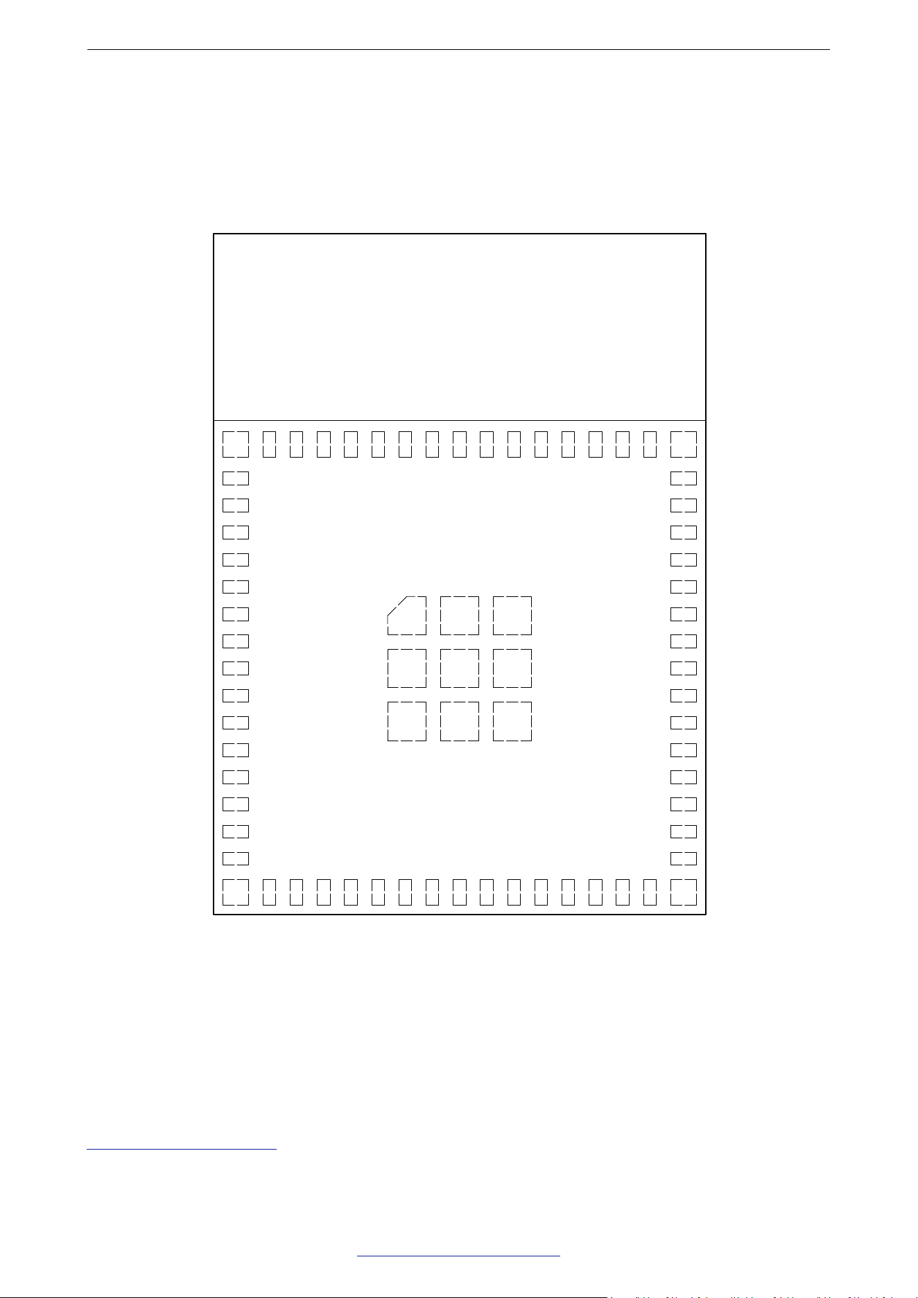
2.1 Pin Layout
The pin diagram below shows the approximate location of pins on the module.
Pin 1
Pin 2
Pin 3
Pin 4
Pin 5
Pin 6
Pin 7
Pin 8
Pin 9
Pin 10
Pin 11
Pin 12
Pin 13
Pin 14
Pin 15
GND
GND
3V3
IO28
NC
IO2
IO3
IO4
IO5
IO6
NC
NC
NC
NC
NC
Pin 63
GND
IO0
Pin 16
Pin 17
Pin 18
Pin 19
Pin 20
Pin 21
Pin 22
Pin 23
Pin 24
Pin 25
Pin 26
Pin 27
Pin 28
Pin 29
Pin 30
Pin 64
GND
Pin 31
IO1
NC
IO7
IO8
IO9
IO10
IO13
IO14
NC
IO15
NC
NC
NC
NC
Pin 32
Pin 33
Pin 34
Pin 35
Pin 36
Pin 37
Pin 38
Pin 39
Pin 40
Pin 41
Pin 42
Pin 43
Pin 44
Pin 45
Pin 65
GND
Pin 62
GND
Pin 46
Pin 47
Pin 48
Pin 49
Pin 50
Pin 51
Pin 52
Pin 53
Pin 54
Pin 55
Pin 56
Pin 57
Pin 58
Pin 59
Pin 60
Pin 61
GND
GND GND GND
GNDGND
GND GND GND
IO23
IO24
IO25
IO26
IO27
NC
NC
NC
TX0
RX0
NC
GND
GND
NC
EN
GND
GND
GND
NC
GND
GND
GND
GND
GND
GND
GND
GND
GND
GND
GND
Keepout Zone
Figure 1: Pin Layout (Top View)
2.2 Pin Description
The module has 65 pins. See pin denitions in Table 2 Pin Description.
For explanations of pin names and function names, as well as congurations of peripheral pins, please refer to
ESP32-C5 Series Datasheet.
Espressif Systems 5
Submit Documentation Feedback
ESP32-C5-MINI-1 User Manual v1.0

2 Pin Denitions
Table 2: Pin Denitions
Name No. Type
1
Function
GND 1, 2, 42, 43, 46-48, 50-65 P Ground
3V3 3 P Power supply
IO28 4 I/O/T GPIO28
NC 5, 11-15, 18, 25, 27-30, 36-38, 41, 44, 49 - NC
IO2 6 I/O/T
MTMS, GPIO2, LP_GPIO2, LP_UART_RTSN,
LP_I2C_SDA, ADC1_CH1, FSPIQ
IO3 7 I/O/T
MTDI, GPIO3, LP_GPIO3, LP_UART_CTSN,
LP_I2C_SCL, ADC1_CH2
IO4 8 I/O/T
MTCK, GPIO4, LP_GPIO4, LP_UART_RXD,
ADC1_CH3, FSPIHD
IO5 9 I/O/T
MTDO, GPIO5, LP_GPIO5, LP_UART_TXD,
ADC1_CH4, FSPIWP
IO6 10 I/O/T GPIO6, LP_GPIO6, ADC1_CH5, FSPICLK
IO0 16 I/O/T GPIO0, XTAL_32K_P, LP_GPIO0, LP_UART_DTRN
IO1 17 I/O/T
GPIO1, XTAL_32K_N, LP_GPIO1, LP_UART_DSRN,
ADC1_CH0
IO7 19 I/O/T GPIO7, FSPID, SDIO_DATA1
IO8 20 I/O/T GPIO8, PAD_COMP0, SDIO_DATA0
IO9 21 I/O/T GPIO9, PAD_COMP1, SDIO_CLK
IO10 22 I/O/T GPIO10, FSPICS0, SDIO_CMD
IO13 23 I/O/T GPIO13, USB_D-, SDIO_DATA3
IO14 24 I/O/T GPIO14, USB_D+, SDIO_DATA2
IO15 26 I/O/T SPICS1, GPIO15
IO23 31 I/O/T GPIO23
IO24 32 I/O/T GPIO24
IO25 33 I/O/T GPIO25
IO26 34 I/O/T GPIO26
IO27 35 I/O/T GPIO27
TX0 39 I/O/T U0TXD, GPIO11
RX0 40 I/O/T U0RXD, GPIO12
EN 45 I
High: on, enables the chip.
Low: off, the chip powers off.
Note: Do not leave the EN pin oating.
1
P: power supply; I: input; O: output; T: high impedance.
Espressif Systems 6
Submit Documentation Feedback
ESP32-C5-MINI-1 User Manual v1.0
3 Get Started
3 Get Started
3.1 What You Need
To develop applications for module you need:
• 1 x ESP32-C5-MINI-1
• 1 x Espressif RF testing board
• 1 x USB-to-Serial board
• 1 x Micro-USB cable
• 1 x PC running Linux
In this user guide, we take Linux operating system as an example. For more information about the
conguration on Windows and macOS, please refer to ESP-IDF Programming Guide for ESP32-C5.
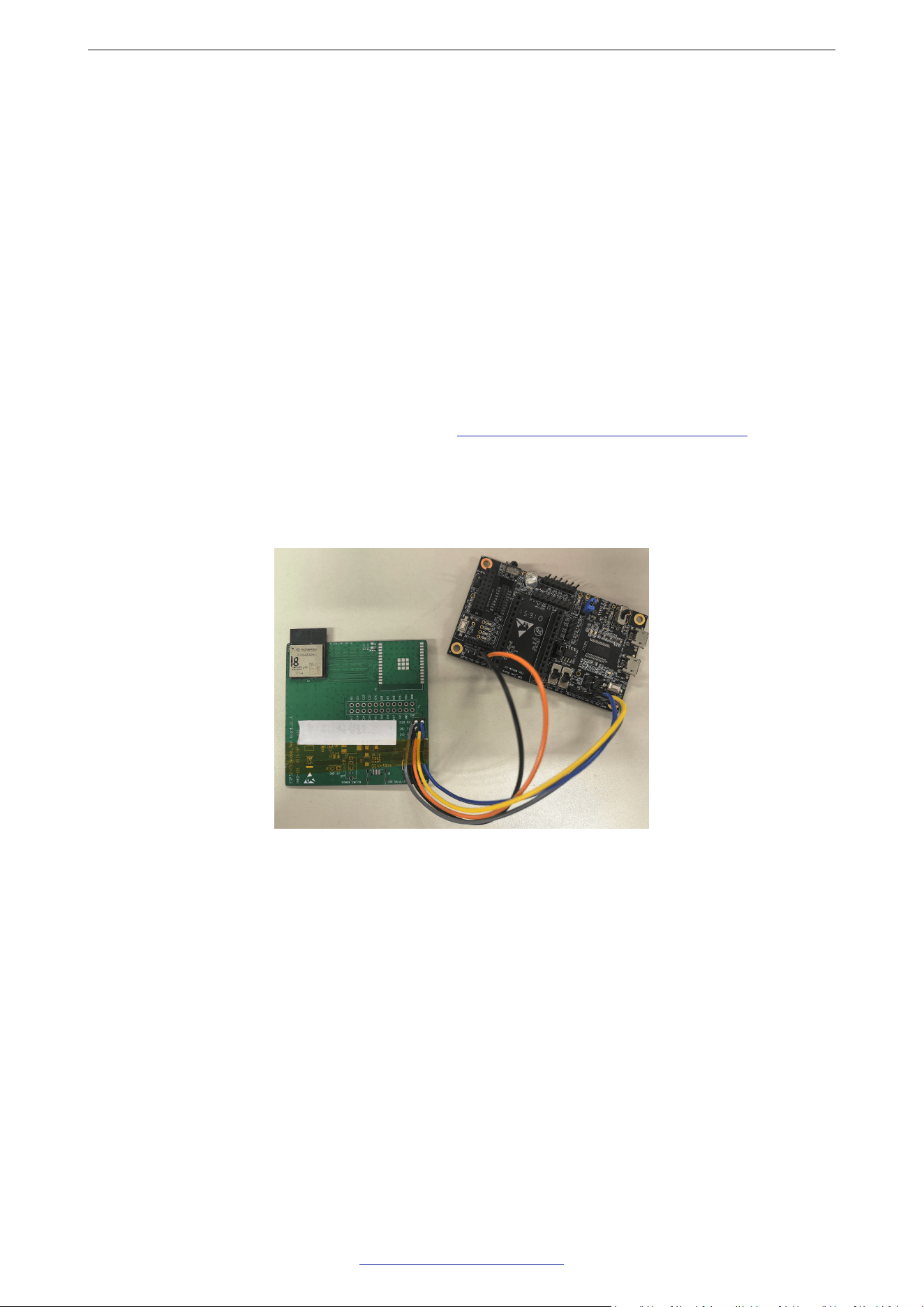
3.2 Hardware Connection
1. Solder the ESP32-C5-MINI-1 module to the RF testing board as shown in Figure 2.
Figure 2: Hardware Connection
2. Connect the RF testing board to the USB-to-Serial board via TXD, RXD, and GND.
3. Connect the USB-to-Serial board to the PC.
4. Connect the RF testing board to the PC or a power adapter to enable 5 V power supply, via the
Micro-USB cable.
5. During download, connect IO28 to GND via a jumper. Then, turn ”ON” the testing board.
6. Download rmware into ash. For details, see the sections below.
7. After download, remove the jumper on IO28 and GND.
8. Power up the RF testing board again. The module will switch to working mode. The chip will read
programs from ash upon initialization.
Espressif Systems 7
Submit Documentation Feedback
ESP32-C5-MINI-1 User Manual v1.0

3 Get Started
Note:
IO28 is internally logic high. If IO28 is set to pull-up, the Boot mode is selected. If this pin is pull-down or left oating, the
Download mode is selected. For more information on ESP32-C5-MINI-1, please refer to ESP32-C5 Series Datasheet.
3.3 Set up Development Environment
The Espressif IoT Development Framework (ESP-IDF for short) is a framework for developing applications
based on the Espressif ESP32. Users can develop applications with ESP32-C5 in Windows/Linux/macOS
based on ESP-IDF. Here we take Linux operating system as an example.
3.3.1 Install Prerequisites
To compile with ESP-IDF you need to get the following packages:
• CentOS 7 & 8:
1 sudo yum -y update && sudo yum install git wget flex bison gperf python3
cmake ninja-build ccache dfu-util libusbx
• Ubuntu and Debian:
1 sudo apt-get install git wget flex bison gperf python3 python3-pip python3-
venv cmake ninja-build ccache libffi-dev libssl-dev dfu-util libusb-1.0-0
• Arch:
1 sudo pacman -S --needed gcc git make flex bison gperf python cmake ninja
ccache dfu-util libusb
Note:
• This guide uses the directory ~/esp on Linux as an installation folder for ESP-IDF.
• Keep in mind that ESP-IDF does not support spaces in paths.
3.3.2 Get ESP-IDF
To build applications for ESP32-C5-MINI-1 module, you need the software libraries provided by Espressif in
ESP-IDF repository.
To get ESP-IDF, create an installation directory (~/esp) to download ESP-IDF to and clone the repository with
‘git clone’:
1 mkdir -p ~/esp
2 cd ~/esp
3 git clone --recursive https://github.com/espressif/esp-idf.git
ESP-IDF will be downloaded into ~/esp/esp-idf. Consult ESP-IDF Versions for information about which ESP-IDF
version to use in a given situation.
Espressif Systems 8
Submit Documentation Feedback
ESP32-C5-MINI-1 User Manual v1.0

3 Get Started
3.3.3 Set up Tools
Aside from the ESP-IDF, you also need to install the tools used by ESP-IDF, such as the compiler, debugger,
Python packages, etc. ESP-IDF provides a script named ’install.sh’ to help set up the tools in one go.
1 cd ~/esp/esp-idf
2 ./install.sh esp32c5
3.3.4 Set up Environment Variables
The installed tools are not yet added to the PATH environment variable. To make the tools usable from the
command line, some environment variables must be set. ESP-IDF provides another script ’export.sh’ which
does that. In the terminal where you are going to use ESP-IDF, run:
1 . $HOME/esp/esp-idf/export.sh
Now everything is ready, you can build your rst project on ESP32-C5-MINI-1 module.
3.4 Create Your First Project
3.4.1 Start a Project
Now you are ready to prepare your application for ESP32-C5-MINI-1 module. You can start with
get-started/hello_world project from examples directory in ESP-IDF.
Copy get-started/hello_world to ~/esp directory:
1 cd ~/esp
2 cp -r $IDF_PATH/examples/get-started/hello_world .
There is a range of example projects in the examples directory in ESP-IDF. You can copy any project in the
same way as presented above and run it. It is also possible to build examples in-place, without copying them
rst.
3.4.2 Connect Your Device
Now connect your module to the computer and check under what serial port the module is visible. Serial
ports in Linux start with ‘/dev/tty’ in their names. Run the command below two times, rst with the board
unplugged, then with plugged in. The port which appears the second time is the one you need:
1 ls /dev/tty*
Note:
Keep the port name handy as you will need it in the next steps.
3.4.3 Congure
Navigate to your ‘hello_world’ directory from Step 3.4.1. Start a Project, set ESP32-C5 chip as the target and
run the project conguration utility ‘menucong’.
Espressif Systems 9
Submit Documentation Feedback
ESP32-C5-MINI-1 User Manual v1.0
3 Get Started
1
cd ~/esp/hello_world
2 idf.py set-target esp32c5
3 idf.py menuconfig
Setting the target with ‘idf.py set-target ESP32-C5’ should be done once, after opening a new project. If the
project contains some existing builds and conguration, they will be cleared and initialized. The target may be
saved in environment variable to skip this step at all. See Selecting the Target for additional information.
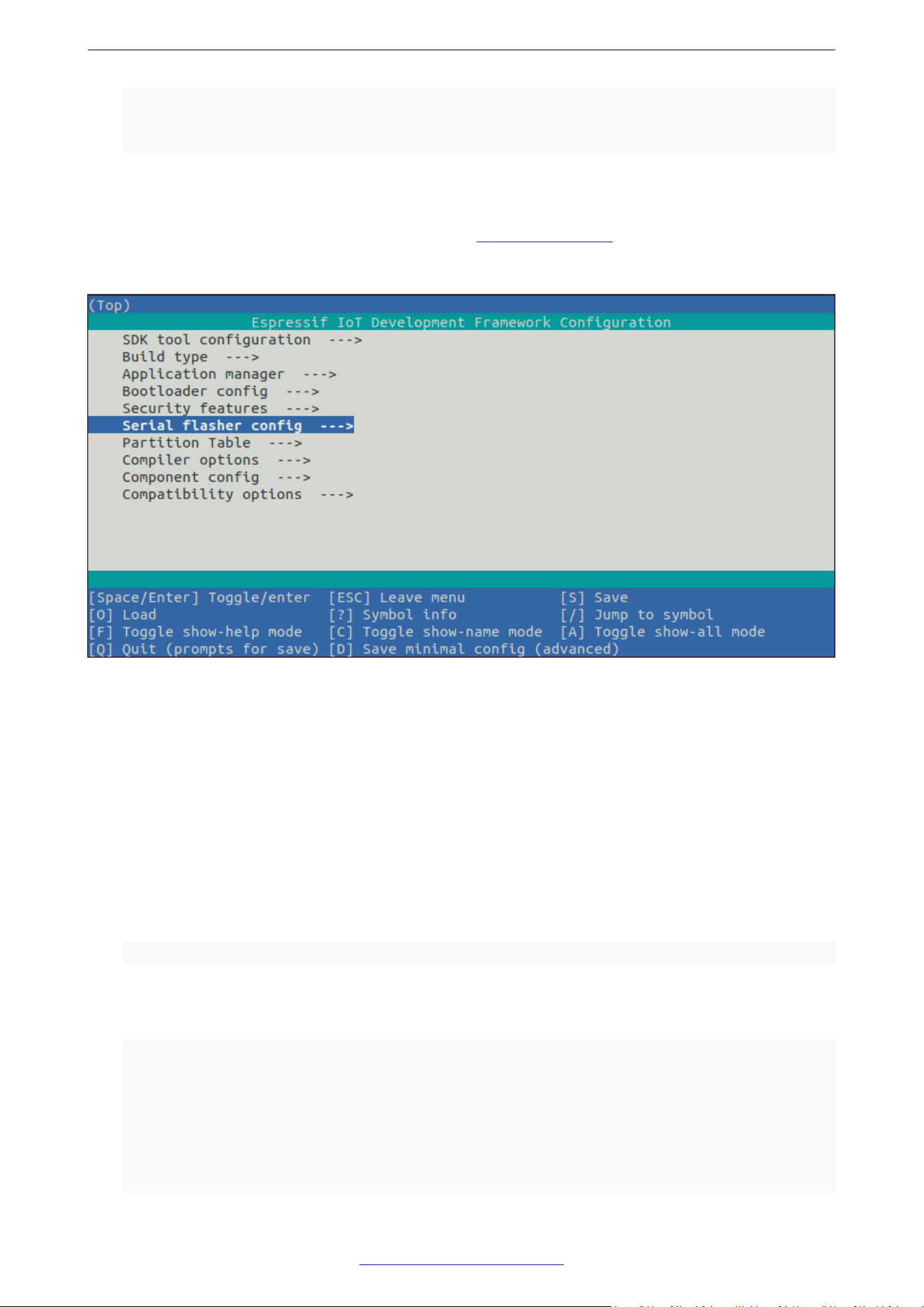
If the previous steps have been done correctly, the following menu appears:
Figure 3: Project Conguration - Home Window
You are using this menu to set up project specic variables, e.g. Wi-Fi network name and password, the
processor speed, etc. Setting up the project with menucong may be skipped for “hello_word”. This example
will run with default conguration
The colors of the menu could be different in your terminal. You can change the appearance with the option
‘--style’. Please run ‘idf.py menucong --help’ for further information.
3.4.4 Build the Project
Build the project by running:
1 idf.py build
This command will compile the application and all ESP-IDF components, then it will generate the bootloader,
partition table, and application binaries.
1 $ idf.py build
2 Running cmake in directory /path/to/hello_world/build
3 Executing ”cmake -G Ninja --warn-uninitialized /path/to/hello_world”...
4 Warn about uninitialized values.
5 -- Found Git: /usr/bin/git (found version ”2.17.0”)
6 -- Building empty aws_iot component due to configuration
7 -- Component names: ...
Espressif Systems 10
Submit Documentation Feedback
ESP32-C5-MINI-1 User Manual v1.0

3 Get Started
8
-- Component paths: ...
9
10 ... (more lines of build system output)
11
12 [527/527] Generating hello_world.bin
13 esptool.py v2.3.1
14
15 Project build complete. To flash, run this command:
16 ../../../components/esptool_py/esptool/esptool.py -p (PORT) -b 921600 write_flash --
flash_mode dio --flash_size detect --flash_freq 40m 0x10000 build/hello_world.bin
build 0x1000 build/bootloader/bootloader.bin 0x8000 build/partition_table/
partition-table.bin
17 or run ’idf.py -p PORT flash’
If there are no errors, the build will nish by generating the rmware binary .bin le.
3.4.5 Flash onto the Device
Flash the binaries that you just built onto your module by running:
1 idf.py -p PORT flash
Replace PORT with your ESP32-C5 board’s serial port name from Step: Connect Your Device.
You can also change the asher baud rate by replacing BAUD with the baud rate you need. The default baud
rate is 460800.
For more information on idf.py arguments, see idf.py.
Note:
The option ‘ash‘ automatically builds and ashes the project, so running ‘idf.py build‘ is not necessary.
When ashing, you will see the output log similar to the following:
1 ...
2 esptool.py --chip esp32c5 -p /dev/ttyUSB0 -b 460800 --before=default_reset --after=
hard_reset
3 write_flash --flash_mode dio --flash_freq 80m --flash_size 4MB 0x0 bootloader/
bootloader.bin
4 0x10000 hello_world.bin 0x8000 partition_table/partition-table.bin
5 esptool.py v3.2-dev
6 Serial port /dev/ttyUSB0
7 Connecting....
8 Chip is ESP32-C5
9 Features: WiFi, BLE
10 Crystal is 48MHz
11 MAC: 7c:df:a1:e0:00:64
12 Uploading stub...
13 Running stub...
14 Stub running...
15 Changing baud rate to 460800
16 Changed.
Espressif Systems 11
Submit Documentation Feedback
ESP32-C5-MINI-1 User Manual v1.0

3 Get Started
17
Configuring flash size...
18 Flash will be erased from 0x00000000 to 0x00004fff...
19 Flash will be erased from 0x00010000 to 0x00039fff...
20 Flash will be erased from 0x00008000 to 0x00008fff...
21 Compressed 18896 bytes to 11758...
22 Writing at 0x00000000... (100 %)
23 Wrote 18896 bytes (11758 compressed) at 0x00000000 in 0.5 seconds (effective 279.9
kbit/s)...
24 Hash of data verified.
25 Compressed 168208 bytes to 88178...
26 Writing at 0x00010000... (16 %)
27 Writing at 0x0001a80f... (33 %)
28 Writing at 0x000201f1... (50 %)
29 Writing at 0x00025dcf... (66 %)
30 Writing at 0x0002d0be... (83 %)
31 Writing at 0x00036c07... (100 %)
32 Wrote 168208 bytes (88178 compressed) at 0x00010000 in 2.4 seconds (effective 569.2
kbit/s)...
33 Hash of data verified.
34 Compressed 3072 bytes to 103...
35 Writing at 0x00008000... (100 %)
36 Wrote 3072 bytes (103 compressed) at 0x00008000 in 0.1 seconds (effective 478.9 kbit/
s)...
37
Hash of data verified.
38
39 Leaving...
40 Hard resetting via RTS pin...
41 Done
If there are no issues by the end of the ash process, the board will reboot and start up the “hello_world”
application.
3.4.6 Monitor
To check if “hello_world” is indeed running, type ‘idf.py -p PORT monitor‘ (Do not forget to replace PORT with
your serial port name).
This command launches the IDF Monitor application:
1 $ idf.py -p /dev/ttyUSB0 monitor
2 Running idf_monitor in directory [...]/esp/hello_world/build
3 Executing ”python [...]/esp-idf/tools/idf_monitor.py -b 115200
4 [...]/esp/hello_world/build/hello-world.elf”...
5 --- idf_monitor on /dev/ttyUSB0 115200 ---
6 --- Quit: Ctrl+] | Menu: Ctrl+T | Help: Ctrl+T followed by Ctrl+H ---
7 ets Jun 8 2016 00:22:57
8
9 rst:0x1 (POWERON_RESET),boot:0x13 (SPI_FAST_FLASH_BOOT)
10 ets Jun 8 2016 00:22:57
11 ...
After startup and diagnostic logs scroll up, you should see “Hello world!” printed out by the application.
Espressif Systems 12
Submit Documentation Feedback
ESP32-C5-MINI-1 User Manual v1.0

3 Get Started
1
...
2 Hello world!
3 Restarting in 10 seconds...
4 This is esp32c5 chip with 1 CPU core, This is esp32c5 chip with 1 CPU core, WiFi/BLE,
5 silicon revision 0, 2MB external flash
6 Minimum free heap size: 390684 bytes
7 Restarting in 9 seconds...
8 Restarting in 8 seconds...
9 Restarting in 7 seconds...
To exit IDF monitor use the shortcut Ctrl+].
That’s all what you need to get started with ESP32-C5-MINI-1 module! Now you are ready to try some other
examples in ESP-IDF, or go right to developing your own applications.
Espressif Systems 13
Submit Documentation Feedback
ESP32-C5-MINI-1 User Manual v1.0

4 U.S. FCC Statement
4 U.S. FCC Statement
The device complies with KDB 996369 D03 OEM Manual v01. Below are integration instructions for host
product manufacturers according to the KDB 996369 D03 OEM Manual v01.
List of Applicable FCC Rules
FCC Part 15 Subpart C 15.247 & Part15.407
Specic Operational Use Conditions
The module has WiFi, BLE and Thread functions.
• Operation Frequency:
– WiFi: 2.4G: 2412 ~ 2462 MHz 5G: 5150 ~ 5850 MHz
– Bluetooth: 2402 ~ 2480 MHz
– Zigbee: 2405 ~ 2480 MHz
– Thread: 2405 ~ 2480 MHz
• Number of Channel:
– WiFi: 2.G�11 5G: 20Mhz� 25�CH36 CH165� 40Mhz� 12�CH38 CH159�
– Bluetooth: 40
– Zigbee/Thread: 16
• Modulation:
– WiFi: 2.4G : BPSK/QPSK/16QAM/64QAM/256QAM/DBPSK/DQPSK/CCK 5G: OFDM, OFDMA
– Bluetooth: GFSK
– Zigbee: O-QPSK
– Thread: O-QPSK
• Type: PCB Antenna
• Gain:
– 2.4G max gain: 4.44 dBi
– 5G max gain: 2.18 dBi
The module can be used for IoT applications with a maximum 4.44 dBi antenna (2.4G) or a maximum 2.18 dBi
antenna (5G). The host manufacturer installing this module into their product must ensure that the nal
composit product complies with the FCC requirements by a technical assessment or evaluation to the FCC
rules, including the transmitter operation. The host manufacturer has to be aware not to provide information to
the end user regarding how to install or remove this RF module in the user’s manual of the end product which
integrates this module. The end user manual shall include all required regulatory information/warning as show
in this manual.
Espressif Systems 14
Submit Documentation Feedback
ESP32-C5-MINI-1 User Manual v1.0

4 U.S. FCC Statement
Limited Module Procedures
Not applicable. The module is a single module and complies with the requirement of FCC Part 15.212.
Trace Antenna Designs
Not applicable. The module has its own antenna, and does not need a host’s printed board microstrip trace
antenna, etc.
RF Exposure Considerations
The module must be installed in the host equipment such that at least 20cm is maintained between the
antenna and users’ body; and if RF exposure statement or module layout is changed, then the host product
manufacturer required to take responsibility of the module through a change in FCC ID or new application. The
FCC ID of the module cannot be used on the nal product. In these circumstances, the host manufacturer will
be responsible for re-evaluating the end product (including the transmitter) and obtaining a separate FCC
authorization.
Antennas
Antenna specication are as follows:
• Type: PCB Antenna
• Gain:
– 2.4G max gain: 4.44dBi
– 5G max gain: 2.18 dBi
This device is intended only for host manufacturers under the following conditions:
• The transmitter module may not be co-located with any other transmitter or antenna.
• The module shall be only used with the external antenna(s) that has been originally tested and certied
with this module.
• The antenna must be either permanently attached or employ a ‘unique’ antenna coupler.
As long as the conditions above are met, further transmitter test will not be required. However, the host
manufacturer is still responsible for testing their end-product for any additional compliance requirements
required with this module installed (for example, digital device emissions, PC peripheral requirements,
etc.).
Label and Compliance Information
Host product manufacturers need to provide a physical or e-label stating “Contains FCC ID:
2AC7Z-ESPC5MINI1” with their nished product.
Information on test modes and additional testing requirements
• Operation Frequency:
– WiFi: 2G: 2412 ~ 2462 MHz 5G: 5150 ~5850 MHz
Espressif Systems 15
Submit Documentation Feedback
ESP32-C5-MINI-1 User Manual v1.0

4 U.S. FCC Statement
– Bluetooth: 2402 ~ 2480 MHz
– Zigbee: 2405 ~ 2480 MHz
– Thread: 2405 ~ 2480 MHz
• Number of Channel:
– WiFi:2.4G 11 ; 5G�20Mhz� 25�CH36 CH165� 40Mhz� 12�CH38 CH159�
– Bluetooth: 40
– Zigbee/Thread: 16
• Modulation:
– WiFi: 2.4G: BPSK/QPSK/16QAM/64QAM/256QAM/DBPSK/DQPSK/CCK; 5G: OFDM, OFDMA
– Bluetooth: GFSK
– Zigbee: O-QPSK
– Thread: O-QPSK
Host manufacturer must perform test of radiated and conducted emission and spurious emission, etc.,
according to the actual test modes for a stand-alone modular transmitter in a host, as well as for multiple
simultaneously transmitting modules or other transmitters in a host product. Only when all the test results of
test modes comply with FCC requirements, then the end product can be sold legally.
Additional testing, Part 15 Subpart B compliant
The modular transmitter is only FCC authorized for FCC Part 15 Subpart C 15.247 and that the host product
manufacturer is responsible for compliance to any other FCC rules that apply to the host not covered by the
modular transmitter grant of certication. If the grantee markets their product as being Part 15 Subpart B
compliant (when it also contains unintentional-radiator digital circuity), then the grantee shall provide a notice
stating that the nal host product still requires Part 15 Subpart B compliance testing with the modular
transmitter installed.
This equipment has been tested and found to comply with the limits for a Class B digital device, pursuant to
Part15 of the FCC Rules. These limits are designed to provide reasonable protection against harmful
interference in a residential installation. This equipment generates, uses and can radiate radio frequency
energy and, if not installed and used in accordance with the instructions, may cause harmful interference to
radio communications.
However, there is no guarantee that interference will not occur in a particular installation. If this equipment does
cause harmful interference to radio or television reception, which can be determined by turning the equipment
off and on, the user is encouraged to try to correct the interference by one of the following measures:
• Reorient or relocate the receiving antenna.
• Increase the separation between the equipment and receiver.
• Connect the equipment into an outlet on a circuit different from that to which the receiver is connected.
• Consult the dealer or an experienced radio/TV technician for help.
This device complies with Part 15 of the FCC Rules. Operation is subject to the following two conditions:
• This device may not cause harmful interference.
Espressif Systems 16
Submit Documentation Feedback
ESP32-C5-MINI-1 User Manual v1.0

4 U.S. FCC Statement
• This device must accept any interference received, including interference that may cause undesired
operation.
Caution:
Any changes or modications not expressly approved by the party responsible for compliance could void the user’s
authority to operate the equipment.
This equipment complies with FCC RF radiation exposure limits set forth for an uncontrolled environment. This
device and its antenna must not be co-located or operating in conjunction with any other antenna or
transmitter. The antennas used for this transmitter must be installed to provide a separation distance of at least
20 cm from all persons and must not be co-located or operating in conjunction with any other antenna or
transmitter.
OEM Integration Instructions
This device is intended only for OEM integrators under the following conditions:
• The transmitter module may not be co-located with any other transmitter or antenna.
• The module shall be only used with the external antenna(s) that has been originally tested and certied
with this module.
As long as the conditions above are met, further transmitter test will not be required. However, the OEM
integrator is still responsible for testing their end-product for any additional compliance requirements required
with this module installed (for example, digital device emissions, PC peripheral requirements, etc.).
Validity of Using the Module Certication
In the event that these conditions cannot be met (for example certain laptop congurations or co-location
with another transmitter), then the FCC authorization for this module in combination with the host equipment
is no longer considered valid and the FCC ID of the module cannot be used on the nal product. In these
circumstances, the OEM integrator will be responsible for re-evaluating the end product (including the
transmitter) and obtaining a separate FCC authorization.
End Product Labeling
The nal end product must be labeled in a visible area with the following: “Contains Transmitter Module FCC
ID: 2AC7Z-ESPC5MINI1”.
Espressif Systems 17
Submit Documentation Feedback
ESP32-C5-MINI-1 User Manual v1.0

Related Documentation and Resources
Related Documentation and Resources
Related Documentation
• ESP32-C5 Series Datasheet – Specications of the ESP32-C5 hardware.
• ESP32-C5 Technical Reference Manual – Detailed information on how to use the ESP32-C5 memory and periph-
erals.
• ESP32-C5 Hardware Design Guidelines – Guidelines on how to integrate the ESP32-C5 into your hardware prod-
uct.
• ESP32-C5 Series SoC Errata – Descriptions of known errors in ESP32-C5 series of SoCs.
• Certicates
https://espressif.com/en/support/documents/certicates
• ESP32-C5 Product/Process Change Notications (PCN)
https://espressif.com/en/support/documents/pcns?keys=ESP32-C5
• ESP32-C5 Advisories – Information on security, bugs, compatibility, component reliability.
https://espressif.com/en/support/documents/advisories?keys=ESP32-C5
• Documentation Updates and Update Notication Subscription
https://espressif.com/en/support/download/documents
Developer Zone
• ESP-IDF Programming Guide for ESP32-C5 – Extensive documentation for the ESP-IDF development framework.
• ESP-IDF and other development frameworks on GitHub.
https://github.com/espressif
• ESP32 BBS Forum – Engineer-to-Engineer (E2E) Community for Espressif products where you can post questions,
share knowledge, explore ideas, and help solve problems with fellow engineers.
https://esp32.com/
• ESP-FAQ – A summary document of frequently asked questions released by Espressif.
https://espressif.com/projects/esp-faq/en/latest/index.html
• The ESP Journal – Best Practices, Articles, and Notes from Espressif folks.
https://blog.espressif.com/
• See the tabs SDKs and Demos, Apps, Tools, AT Firmware.
https://espressif.com/en/support/download/sdks-demos
Products
• ESP32-C5 Series SoCs – Browse through all ESP32-C5 SoCs.
https://espressif.com/en/products/socs?id=ESP32-C5
• ESP32-C5 Series Modules – Browse through all ESP32-C5-based modules.
https://espressif.com/en/products/modules?id=ESP32-C5
• ESP32-C5 Series DevKits – Browse through all ESP32-C5-based devkits.
https://espressif.com/en/products/devkits?id=ESP32-C5
• ESP Product Selector – Find an Espressif hardware product suitable for your needs by comparing or applying lters.
https://products.espressif.com/#/product-selector?language=en
Espressif Systems 18
Submit Documentation Feedback
ESP32-C5-MINI-1 User Manual v1.0

Related Documentation and Resources
Contact Us
• See the tabs Sales Questions, Technical Enquiries, Circuit Schematic & PCB Design Review, Get Samples
(Online stores), Become Our Supplier, Comments & Suggestions.
https://espressif.com/en/contact-us/sales-questions
Espressif Systems 19
Submit Documentation Feedback
ESP32-C5-MINI-1 User Manual v1.0


Disclaimer and Copyright Notice
Information in this document, including URL references, is subject to change without notice.
ALL THIRD PARTY’S INFORMATION IN THIS DOCUMENT IS PROVIDED AS IS WITH NO WARRANTIES TO ITS AUTHENTICITY AND
ACCURACY.
NO WARRANTY IS PROVIDED TO THIS DOCUMENT FOR ITS MERCHANTABILITY, NON-INFRINGEMENT, FITNESS FOR ANY PARTICULAR
PURPOSE, NOR DOES ANY WARRANTY OTHERWISE ARISING OUT OF ANY PROPOSAL, SPECIFICATION OR SAMPLE.
All liability, including liability for infringement of any proprietary rights, relating to use of information in this document is disclaimed. No
licenses express or implied, by estoppel or otherwise, to any intellectual property rights are granted herein.
The Wi-Fi Alliance Member logo is a trademark of the Wi-Fi Alliance. The Bluetooth logo is a registered trademark of Bluetooth SIG.
All trade names, trademarks and registered trademarks mentioned in this document are property of their respective owners, and are
hereby acknowledged.
Copyright © 2026 Espressif Systems (Shanghai) Co., Ltd. All rights reserved.
.espressif.com